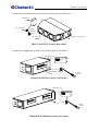
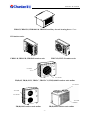
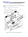
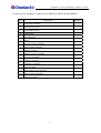
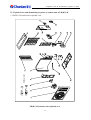
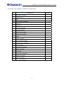
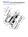
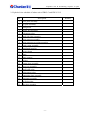
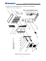
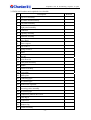
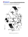
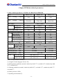
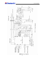
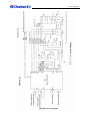
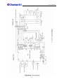
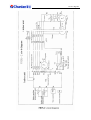
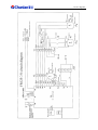
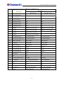
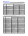
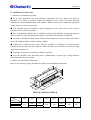
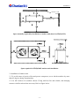
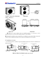
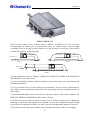
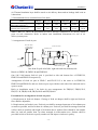
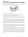
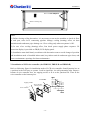
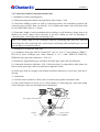
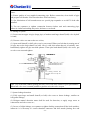
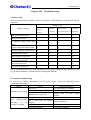
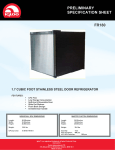
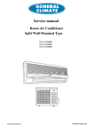
1
Structure & Features
Air duct Type Air Conditioner
Service Manual
JIANGSU CHUNLAN REFRIGERATING EQUIPMENT Co., Ltd.
AUGUST 2004
Structure & Features
Contents
Chapter I
Structure & features ........................................................................................... 1
Chapter II
Exploded views & dismantling sequence of parts ............................................. 4
Chapter III
Main technical parameters ............................................................................... 34
Chapter IV
Performance curve ........................................................................................... 40
Chapter V
Circuit diagrams............................................................................................... 41
Chapter VI
List of main parts and wear parts..................................................................... 59
Chapter VII
Type selection .................................................................................................. 65
Chapter VIII
Installation ....................................................................................................... 66
Chapter IX
Air duct design & noise reduction ................................................................... 83
Chapter X
Method of operation ........................................................................................ 89
Chapter XI
Maintenance..................................................................................................... 94
Chapter XII
Troubleshooting ............................................................................................... 95
Chapter XIII Typical case analysis...................................................................................... 109
i
Structure & Features
Chapter I
Structure & features
I. Brief introduction
This air duct type air conditioner is our latest home (commercial) centralized air conditioning
product. This product features high efficiency, energy saving, mild and silent operation,
computerized intelligent control and healthy fresh air etc. In addition, wire and wireless
controls are provided for easy operation. The product can be widely used in large area,
multi-room composite compartment/houses, villa, and medium and small restaurants, bars,
leisure and recreation sites.
II. Indoor unit
1. Indoor unit of low static pressure series air duct type air conditioner
Mounting hole
Fan
Return air box (optional)
Air exhaust
PTC aux. electric
heating
Wire controller
Remote controller
Water outlet
Return air port
Fresh air port
FRD23-B, FRD35-B & FRD50-B indoor unit outline
Electric
box
Air exhaust
Wire controller
Mounting hole
Evaporator
FR(D)71-B & FR(D)100-B indoor unit outline
-1-
Remote
controller
Structure & Features
2. Indoor unit of medium static pressure series air duct type air conditioner
Electric box
Wire controller
Remote
controller
Air exhaust
Lifting lug mounting position
FR95-C & FR125-C/S indoor unit outline
3. Indoor unit of high static pressure series air duct type air conditioner
Mounting strip
Electric
box
Wire controller
Air exhaust
Remote
controller
FR(D)95 & FR(D)125/S indoor unit outline
Mounting strip
Electric
box
Wire
controller
Air exhaust
FR(D)180/S & FR(D)260/S indoor unit outline
-2-
Remote
controller
Structure & Features
Air intake
FRD95, FRD125/S, FRD180/S & FRD20/S auxiliary electric heating box outline
III Outdoor units
FRD23-B, FRD35-B, FRD50-B outdoor unit
FRD71-B, FR71-B outdoor unit
Air intake
Air exhaust
FR(D)95, FR(D)125/S, FR95-C, FR125-C/S, FR(D)100-B outdoor unit outline
Air exhaust
Air intake
Air exhaust
Air intake
FR(D)180/S outdoor unit outline
FR(D)260/S outdoor unit outline
-3-
Exploded view & dismantling sequence of parts
Chapter II
Exploded views & dismantling sequence of parts
I. Exploded view & dismantling sequence of indoor unit of FRD23-B, FRD35-B and
FRD50-B
1. Exploded view of FRD23-B, FRD35-B and FRD50-B indoor unit
Exploded view of indoor unit of FRD23-B, FRD35-B & FRD50-B
-4-
Exploded view & dismantling sequence of parts
2. Exploded view schedule for FRD23-B, FRD35-B and FRD50-B in door unit
No.
Description
Remark
1
Air exhaust strip
2
Water tray assembly
3
Water accumulation plate
4
Right side plate assembly
5
Heat exchanger assembly
6
PTC electric heater
7
Heat exchange section top plate assembly
8
Fan section left side plate assembly
9
Impeller
10
Motor
11
Fan section top plate
Optional
12
Fan section rear plate assembly
Optional
13
Spiral casing
14
Fan section right side plate assembly
15
Fan mounting plate
16
Fan section bottom plate
17
Electric box mounting plate
18
Electric box
19
Electric box fixing block
20
Heat exchanger protection plate
21
Left side plate assembly
Optional
Optional
Optional
-5-
Exploded view & dismantling sequence of parts
3. Dismantling sequence of indoor unit of FRD23-B, FRD35-B and FRD50-B
(1) Remove 18
(2) Remove 17, 19
(3) Remove 12
(4) Remove 11
(5) Remove 16
(6) Remove 14, 8
(7) Remove 9, 13
(8) Remove 10
(9) Remove 15
(10) Remove 7, 6
(11) Remove 20
(12) Remove 21, 4
(13) Remove 5
(14) Remove 3, 1
(15) Remove 2.
Annex: Dismantling sequence of typical parts
Indoor capacitor
(1) Remove 12
(2) Remove capacitor.
Indoors motor:
(1) Remove fan section rear plate 12
(2) Remove fan section top plate 11
(3) Remove spiral casing 13 and impeller 9
(4) Remove connecting plug from control board in electric box
(5) Remove motor 10 and capacitor.
Note: Return air box of FRD23-B, FRD35-B or FRD50-B indoor unit is optional. There are
two modes of air return (lower air return and rear air return) and two modes of water
discharge (left and right). This exploded view and dismantling sequence is based on lower air
return and left water discharge.
-6-
Exploded view & dismantling sequence of parts
II. Exploded view and dismantling sequence for outdoor unit of FRD23-B, FRD35-B &
FRD50-B
Outdoor unit
1. Exploded view of outdoor unit of FRD23-B, FRD35-B and FRD50-B
Exploded view of outdoor unit of FRD23-B, FRD35-B and FRD50-B
-7-
Exploded view & dismantling sequence of parts
2. Exploded view schedule of outdoor unit of FRD23-B, FRD35-B and FRD50-B
No.
Description
1
Front plate assembly
2
Small shutoff valve
3
Large shutoff valve
4
Compressor
5
Axial flow fan
6
Motor
7
Reversing valve assembly
8
Left rear plate assembly
9
Handle assembly
10 Outdoor electric assembly
11 Top cover assembly
12 Capillary assembly
13 Condenser assembly
14 Right rear plate
15 Middle baffle plate assembly
16 Motor support assembly
17 Chassis assembly
-8-
Remark
Exploded view & dismantling sequence of parts
3. Dismantling sequence of outdoor unit of RD23-B, FRD35-B and FRD50-B
(1) Remove 11
(2) Remove 8, 9
(3) Remove 14
(4) Remove 1
(5) Remove 10
(6) Remove 5, 6
(7) Remove 16
(8) Remove 2, 3
(9) Remove 15
(10) Remove 7
(11) Remove 12, 13
(12) Remove 4
(13) Remove 17
Annex: Dismantling sequence of typical parts
Outdoor electric assembly:
(1) Remove top cover assembly 11
(2) Remove handle assembly 9
(3) Remove left rear plate assembly 8
(4) Remove outdoor electric assembly 10.
Outdoors motor:
(1) Remove top cover assembly 11
(2) Remote handle assembly 9
(3) Remove front plate assembly 1
(4) Remove fan 5
(5) Remove connecting plug from motor 6 and remove the motor.
Outdoors compressor
(1) Remove top cover assembly 11
(2) Remove handle assembly 9 and left rear plate assembly 8
(3) Remove front plate assembly 1
(4) Remove large and small shutoff valves 3 and 2, and remove reversing valve 7
(5) Remove compressor cable and the compressor.
-9-
Exploded view & dismantling sequence of parts
III. Exploded view and dismantling sequence of indoor unit of FR(D)71-B and
FR(D)100-B
1. Exploded view of indoor unit of FR(D)71-B and FR(D)100-B
Indoor unit
Exploded view of indoor unit of FR(D)71-B and FR(D)100-B
- 10 -
Exploded view & dismantling sequence of parts
2. Exploded view schedule of indoor unit of FR(D)71-B and FR(D)100-B
No.
Remark
Description
1
Air intake plate
2
Top plate assembly
3
Left support
4
PTC electric heater
5
Spiral casing
6
Impeller
7
Left side plate assembly
8
Evaporator assembly
9
Condensate tray assembly
Only for FRD71-B & FRD100-B
10 Bottom plate assembly I
11 Bottom plate assembly II
12 Motor
13 Fan support plate
14 Manger board assembly
15 Right support
16 Right side plate assembly
17 Right small hole cover plate
18 Electric box assembly
- 11 -
Exploded view & dismantling sequence of parts
3. Dismantling sequence of indoor unit of FR(D)71-B and FR(D)100-B
(1) Remove 18
(2) Remove 17
(3) Remove 4, 3, 15
(4) Remove 2
(5) Remove 1
(6) Remove 5, 6
(7) Remove 12
(8) Remove 14
(9) Remove 13
(10) Remove 8
(11) Remove 9
(12) Remove 16, 17
(13) Remove 10, 11
Annex: Dismantling sequence of typical parts
Indoor capacitor
(1) Remove 1
(2) Remove capacitor.
Indoors motor:
(1) Remove electric box 18
(2) Remove plug of indoor motor from control board in electric box.
(3) Remove air intake plate 1
(4) Remove top plate assembly 2 with 3, 4 and 15
(5) Remove spiral casing 5 and impeller 6
(6) Remove motor 12 and capacitor.
Note: FR(D)71-B and FR(D)100-B have two air return modes: lower air return and rear air
return. This exploded view and dismantling sequence is based on rear air return.
- 12 -
Exploded view & dismantling sequence of parts
IV. Exploded view and dismantling sequence of outdoor unit of FR(D)71-B
Outdoor unit
1. FR(D)71-B outdoor unit exploded view
FR(D)71-B outdoor unit exploded view
- 13 -
Exploded view & dismantling sequence of parts
2. Exploded view schedule for FR(D)71-B outdoor unit
No.
Description
1
Front panel assembly
2
Axial flow fan
3
Motor
4
Motor support assembly
5
Condenser
6
Left panel
7
Top cover assembly
8
Air intake grating
9
Baffle plate assembly
10 Right panel assembly
11 Handle
12 Electric assembly
13 Valve support assembly
14 Reversing valve assembly
15 Air suction pipe
16 Steam/water separator
17 Chassis assembly
18 Fixing strip
19 Piston type compressor
20 Capillary assembly
21 Strainer assembly
22 4-way pipe assembly
- 14 -
Remark
Exploded view & dismantling sequence of parts
3. FR(D)71-B outdoor unit dismantling sequence
(1) Remove 7
(2) Remove 11, 13
(3) Remove 1
(4) Remove 10
(5) Remove 8, 6
(6) Remove 18
(7) Remove 2, 3
(8) Remove 4
(9) Remove 12
(10) Remove 14, 15
(11) Remove 16
(12) Remove 9
(13) Remove 20, 21, 22
(14) Remove 19
(15) Remove17
Annex: Dismantling sequence of typical parts
Outdoor electric assembly:
(1) Remove top cover assembly 7
(2) Remove front plate assembly 1
(3) Remove right panel assembly 10, 13
(4) Remove electric assembly 12.
Outdoors motor:
(1) Remove top cover assembly 7
(2) Remove front plate assembly 1
(3) Remove fan 2
(4) Unplug motor 3 and remove the motor.
Outdoors compressor:
(1) Remove top cover assembly 7
(2) Remove front plate assembly 1
(3) Remove right side plate assembly 10
(4) Remove reversing valve assembly 14 and air suction pipe 15
(5) Remove compressor cable and take out the compressor.
- 15 -
Exploded view & dismantling sequence of parts
V. Exploded view and dismantling sequence of indoor unit of FR95-C, FR125-C/S
1. Exploded view of indoor unit of FR95-C and FR125-C/S
- 16 -
Exploded view & dismantling sequence of parts
2. Exploded view schedule of indoor unit of FR95-C and FR125-C/S
No.
Description
1
Cover plate assembly
2
Top plate assembly
3
Lifting hook
4
Electric box assembly
5
Left support plate
6
Small side plate assembly
7
Fixing support assembly
8
Fixing support cover plate assembly
9
Spiral casing assembly
10 Centrifugal impeller
11 Strainer frame
12 Motor
13 Motor support
14 Strainer
15 Bottom plate assembly
16 Water tray assembly
17 Small baffle plate
18 Right support plate
19 Connecting plate assembly
20 Evaporator assembly
21 Fan fixing plate
22 Side plate assembly
- 17 -
Remark
Exploded view & dismantling sequence of parts
3. Dismantling sequence of indoor unit of FR95-C and FR125-C/S
(1) Remove 1
(2) Remove 11, 14
(3) Remove 2
(4) Remove 4, 3
(5) Remove 21
(6) Remove 9, 10
(7) Remove 12, 13
(8) Remove 8
(9) Remove 7
(10) Remove 22
(11) Remove 19
(12) Remove 20
(13) Remove 5, 18, 17
(14) Remove 15
Annex: Dismantling sequence of typical parts
Indoor capacitor:
(1) Remove 1
(2) Remove 11, 14
(3) Remove capacitor.
Indoors motor:
(1) Remove electric box 4
(2) Remove cover plate 2 and strainer frame 11
(3) Remove plug of indoor motor from control board in electric box
(4) Remove fan mounting plate 21
(5) Remove spiral casing 9 and impeller 10
(6) Remove motor support 13
(7) Remove motor 12 and capacitor.
- 18 -
Exploded view & dismantling sequence of parts
VI. Exploded view and dismantling sequence of indoor unit of FR(D)95 and FR(D)125/S
1. Exploded view of indoor unit of FR(D)95 and FR(D)125/S
Exploded view of indoor unit of FR(D)95 and FR(D)125/S
- 19 -
Exploded view & dismantling sequence of parts
2. Exploded view schedule of indoor unit of FR(D)95 and FR(D)125/S
No.
Description
1
Top plate assembly
2
Strainer 1
3
Evaporator assembly
4
Strainer 2
5
Water tray assembly
6
Strainer retaining strip
7
Left side plate assembly
8
Fixing block
9
Left small hole cover plate
10 Square hole cover plate assembly
11 Air intake
12 Bottom plate assembly
13 Impeller
14 Spiral casing assembly
15 Tapping screw ST4X12
16 Front panel assembly
17 Motor
18 Bolt M6X16
19 Motor fixing block
20 Capacitor clip
21 Capacitor
22 Right side plate assembly
23 Right small hole cover plate assembly
24 Mounting strip
25 Bolt with two washers
26 Retainer
- 20 -
Remark
Exploded view & dismantling sequence of parts
3. Dismantling sequence of indoor unit of FR(D)95 and FR(D)125/S
(1) Remove 1;
(2) Remove 2;
(3) Remove 8, 4;
(4) Remove 14, 16;
(5) Remove 23;
(6) Remove 7;
(7) Remove 3;
(8) Remove 5;
(9) Remove 22
Annex: Dismantling sequence of typical parts
Indoor capacitor:
(1) Loosen tapping screws on retainer 26, rotate retainer 26;
(2) Remove right small hole cover plate assembly 10;
(3) Remove capacitor clip 20
Indoor motor:
(1) Loosen tapping screws on retainer 26, rotate retainer 26;
(2) Remove left and right small square hole cover plate assemblies 10 respectively;
(3) Remove left air intake 11, remove impeller 13;
(4) Remove plugs of motor 17 and capacitor 21 from control board;
(5) Remove connecting bolt between motor fixing block 19 and fan spiral casing 14;
(6) Remove motor.
- 21 -
Exploded view & dismantling sequence of parts
VII. Exploded view and dismantling sequence of auxiliary electric heating box of FRD95
and FRD125/S
Exploded view of auxiliary electric heating box of FRD95 and FRD125/S
Exploded view schedule of auxiliary electric heating box of FRD95 and FRD125/S
No.
Description
Remark
1 Top plate
2 Frame assembly
3 Left side plate assembly
4 Bottom plate assembly II
5 Bottom plate assembly I
6 PTC electric heater
7 Right side plate assembly
8 Cover plate
Dismantling sequence of aux. electric heating box PTC of FRD95 and FRD125/S
(1) Remove electric box cover 8 and remove PTC electric heating wire
(2) Remove bottom plate assembly I (part 5)
(3) Remove side frame assembly 3
(4) Remove PTC electric heating wire
- 22 -
Exploded view & dismantling sequence of parts
VIII. Exploded view and dismantling sequence of outdoor unit of FR(D)95, FR(D)125/S,
FR(D)100-B, FR95-C and FR125-C/S
Outdoor unit
1. Exploded view of outdoor unit of FR(D)95, FR(D)125/S, FR(D)100-B, FR95-C &
FR125-C/S
Exploded view of outdoor unit of FR(D)95, FR(D)100-B, FR(D)125/S, FR95-C,
FR125-C/S (example of FR(D)95)
- 23 -
Exploded view & dismantling sequence of parts
2. Exploded view schedule of outdoor unit of FR(D)95, FR(D)125/S, FR(D)100-B, FR95-C &
FR125-C/S
No.
Description
1
Top cover assembly
2
Air intake mesh assembly
4
Right panel assembly
5
Condenser
6
Capillary assembly
7
T-pipe assembly
8
Valve Dg8
9
Motor support
Remark
10 Flat washer 5
11 Spring washer 5
12 Motor
13 Nut M5
14 Axial flow fan
15 Front panel assembly
16 Handle
17 Electric assembly
18 Baffle plate assembly
19 Air exhaust pipe
20 Reversing valve assembly
21 Pipe (2)
22 Pipe (1)
23 Air suction pipe
24 Compressor junction box cover
25
Dg13(FR(D)95,
FR125-C/S)
FR95-C,
FR(D)100-B),
26 Compressor
27 Damper ring
28 Chassis assembly
- 24 -
Dg16
(FR(D)125/S,
Exploded view & dismantling sequence of parts
3. Dismantling sequence of outdoor unit of FR(D)95, FR(D)125/S, FR(D)100-B, FR95-C、&
FR125-C/S
(1) Remove 1;
(2) Remove 2;
(3) Remove 3 and 4 respectively;
(4) Remove 15;
(5) Remove 14 and 9 respectively;
(6) Remove 17;
(7) Remove 5 and 18 respectively
(8) Remove 20 and 26.
Annex: Dismantling sequence of typical parts
Outdoor electric assembly:
(1) Remove top cover 1;
(2) Remove right panel assembly 4;
(3) Remove cover plate on electric assembly 17.
Outdoor motor:
(1) Remove top cover assembly 1;
(2) Remove left panel assembly 3 and right panel assembly 4 respectively;
(3) Remove front panel assembly 15;
(4) Remove fan 14;
(5) Unplug motor 12 and remove motor.
Outdoor compressor:
(1) Remove top cover assembly 1;
(2) Remove right panel assembly 4;
(3) Remove electric assembly 17;
(4) Remove reversing valve assembly 20;
(5) Remove compressor.
- 25 -
Exploded view & dismantling sequence of parts
IX. Exploded view and dismantling sequence of indoor unit of FR(D)180/S and
FR(D)260/S
Indoor unit
1. Exploded view of indoor unit of FR(D)180/S and FR(D)260/S
Exploded view of indoor unit of FR(D)180/S and FR(D)260/S
- 26 -
Exploded view & dismantling sequence of parts
2. Exploded view schedule of indoor unit of FR(D)180/S and FR(D)260/S
No.
Description
1
Top plate assembly
2
Strainer I
3
Evaporator assembly
4
Strainer 2
5
Water tray assembly
6
Strainer retaining strip
7
Left side plate assembly
8
Fixing block
9
Left small hole cover plate
10
Square hole cover plate assembly
11
Air intake
12
Bottom plate assembly
13
Impeller
14
Spiral casing assembly
15
Tapping screw ST4X12
16
Front panel assembly
17
Motor
18
Bolt M6X16
19
Motor fixing block
20
Capacitor clip
21
Capacitor
22
Right side plate assembly
23
Right small hole cover plate assembly
24
Mounting strip
25
Bolt with two washers
26
Retainer
- 27 -
Remark
Exploded view & dismantling sequence of parts
3. Dismantling sequence of indoor unit of FR(D)180/S and FR(D)260/S
(1) Remove 1;
(2) Remove 2;
(3) Remove 8, 4;
(4) Remove 14, 16
(5) Remove 23;
(6) Remove 7;
(7) Remove 3;
(8) Remove 5;
(9) Remove 22.
Annex: Dismantling sequence of typical parts
Indoors right motor capacitor (seen from air exhaust):
(1) Loosen tapping screw on retainer 26, rotate retainer 26;
(2) Remove right small hole cover plate assembly 10
(3) Remove capacitor clip 20.
Indoors left motor capacitor (seen from air exhaust):
(1) Remove 1;
(2) Remove capacitor clip 20.
Indoor motor:
(1) Remove 1;
(2) Remove 14;
(3) Same method as for motor removal for FR(D)95 and FR(D)125/S.
Note: FRD180/S auxiliary electric heating box outline is the same as FRD95 auxiliary electric
heating box; two such boxes are provided. FRD260/S auxiliary electric heating box outline is
the same as FRD125/S auxiliary electric heating box; two such boxes are provided. Method of
dismantling is the same as for FRD95 and FRD125/S auxiliary electric heating box.
- 28 -
Exploded view & dismantling sequence of parts
X. Exploded view and dismantling sequence of outdoor unit of FR(D)180/S
Outdoor unit
1. FR(D)180/S outdoor unit exploded view
FR(D)180/S outdoor unit exploded view
- 29 -
Exploded view & dismantling sequence of parts
2. FR(D)180/S outdoor unit exploded view schedule
No.
Description
1
Top cover assembly
2
Air intake mesh assembly
3
Left panel assembly
4
Right panel assembly
5
Condenser
6
Capillary assembly
7
Manifold assembly
8
Valve Dg10
9
Motor support
10 Flat washer 5
11 Spring washer 5
12 Motor
13 Nut M5
14 Axial flow fan
15 Front panel assembly
16 Handle
17 Electric assembly
18 Cover plate
19 Baffle plate
20 Connecting pipe
21 Air exhaust pipe
22 Steam/water separator
23 Reversing valve assembly
24 Air suction pipe
25 Compressor junction box cover
26 Valve Dg19
27 Compressor
28 Damper ring
29 Chassis assembly
- 30 -
Remark
Exploded view & dismantling sequence of parts
3. FR(D)180/S outdoor unit dismantling sequence
(1) Remove 1;
(2) Remove 2;
(3) Remove 3 and 4 respectively;
(4) Remove 15;
(5) Remove 14 and 9 respectively;
(6) Remove 18 and 17 respectively;
(7) Remove 5 and 19 respectively;
(8) Remove 20 and 27.
Annex: Dismantling sequence of typical parts
A. Outdoor electric assembly
(1) Remove top cover 1;
(2) Remove right panel assembly 4;
(3) Remove cover plate 18 on electric assembly 17.
B. 室外电机
(1) Remove top cover assembly 1;
(2) Remove left panel assembly 3 and right panel assembly 4 respectively;
(3) Remove front panel assembly 15;
(4) Remove fan 14;
(5) Unplug motor 12 and remove the motor.
C. Outdoor compressor
(1) Remove top cover assembly 1;
(2) Remove right panel assembly 4;
(3) Remove electric assembly 17;
(4) Remove reversing valve assembly 20;
(5) Remove compressor.
- 31 -
Exploded view & dismantling sequence of parts
XI. FR(D)260/S outdoor unit exploded view and dismantling sequence
Outdoor unit
1. FR(D)260/S outdoor unit exploded view and dismantling sequence
FR(D)260/S outdoor unit exploded view
- 32 -
Exploded view & dismantling sequence of parts
2. FR(D)260/S outdoor unit schedule
No.
Description
QTY
No.
Description
QTY
1
Maintenance plate
1
21
Support plate assembly
1
2
Left side plate
1
22
Reversing valve assembly
1
3
Tapping screw
23
One-way valve assembly
1
4
Left condenser
1
24
------
--
5
Left air intake assembly
1
25
Air suction pipe assembly
1
6
Left air exhaust pipe ASSY
1
26
Electric heating band
2
7
Connector assembly
1
27
Right condenser
1
8
HP valve assembly
1
28
Right air intake pipe assembly
1
9
LP valve assembly
1
29
Right air exhaust pipe assembly
1
10 Bolt M8×30
12
30
Connector assembly
1
11 Washer 8
12
31
Right side plate assembly
1
12 Spring washer
8
32
Air/water separator
1
13 Nut
8
33
Compressor
1
14 Air hood assembly
2
34
Bolt M8×50
4
15 Axial flow fan
2
35
Washer 8
4
16 Motor
2
36
Liner tube
4
17 Motor support
1
37
Damper
4
18 Support assembly
1
38
Chassis
1
19 Control box
1
39
Enclosing plate
1
20 Support strip assembly
1
40
Fixing plate
1
3. FR(D)260/S outdoor unit dismantling sequence
(1) Remove 14, 1 and 39;
(2) Remove 2, 31, 21, 20, 19;
(3) Remove fan assembly (15, 16, 17);
(4) Remove 4, 27, 18, 8;
(5) Remove 10, 22, 23, 25;
(6) Remove 33, 32 respectively.
- 33 -
Main technical parameters
Chapter III Main technical parameters
I. Main technical parameters of FRD23-B, FRD35-B and FRD50-B
Model
Rated
W
cooling
capacity
Rated
W
heating
capacity
FRD23-B
FRD35-B
FRD50-B
2300
3500
5000
2300(850)
3500(1200)
5000(1500)
Power supply
220V~50Hz
Rated input Cooling W/A
890/4.1
1340/6.2
1950/8.9
Power/Curr Heating W/A
790(850)/3.6(4.0)
1320(1200)/6.0(5.5)
1850(1500)/8.4(6.8)
420
600
800
Air flow (indoor unit) m3/h
Static exhaust air pressure Pa
Mass
Noise
20
Indoor unit kg
24
25.5
28
Outdoor unit kg
28
35
52
Indoor unit dB(A)
≤38
≤44
≤48
Outdoor unit dB(A)
≤50
≤52
≤56
R22/0.71
R22/1.24
R22/1.6
Refrigerant
kg
Connecting Liquid pipe mm
pipe size
Air pipe mm
ф6
ф10
ф12
Air exhaust size
mm
128×722
128×922
Return air port size
mm
170×680
170×880
Fresh air port size
mm
Outline
Indoor unit mm
L×W×H Outdoor unit mm
100×100
888×466×234
1088×466×234
650×250×551
800×252×646
Notes: 1. Experimental conditions:
(1) Length of connecting pipe for test: 5m;
(2) Refrigeration conditions (normal): indoor dry bulb 27℃, wet bulb 19℃; Outdoor dry bulb
35℃, wet bulb 24℃;
(3) Heating conditions (normal): indoor dry bulb 20℃, wet bulb 15℃; outdoor dry bulb 7℃,
wet bulb 6℃;
(4) Static pressure is 20Pa
2. Operating environment (T):
- 34 -
Main technical parameters
Cooling:
15℃<T<32℃ (indoor)
Heating: 12℃<T<27℃ (indoor)
18℃<T<43℃ (outdoor)
-7℃<T<24℃ (outdoor)
3. Value in “(
)” is nominal value of auxiliary electric heating;
4. Return air port size based on optional return air box size.
II. Main technical parameters for FR(D)71-B and FR(D)100-B
Model
FR71-B
Rated cooling capacity
Rated heating capacity
FRD71-B
FR100-B
7100W
7500W
FRD100-B
10000W
7500(2300)W
Power supply
10500W
10500(2300)
W
220V~50Hz
Rated input Cooling
power
Heating
Rated input Cooling
current
Heating
2760W
3900W
2420W
3100W
13.4A
17.8A
11.8 A
11.8(10.5) A
14.2 A
14.2(10.5) A
1500 m3/h
Air circulation flow
2000 m3/h
Air exhaust static pressure
30Pa
Indoor unit noise
54dB(A)
56dB(A)
Outdoor unit noise
60 dB(A)
62dB(A)
Mass
Indoor unit
44 Kg
46 Kg
Outdoor unit
Filling of refrigerant
60 Kg
62 Kg
78 Kg
85 Kg
R22/2.7 Kg
R22/3.3 Kg
Conn. pipe Liquid pipe
size (user)
Steam pipe
Liquid pipe φ10×1
Steam pipe φ16×1
Outline
Ind. unit mm
1260×555×226 mm
1880×555×226 mm
W×D×H
Outd Unit mm
950×370×746 mm
950×420×853 mm
Notes:
(1) Length of connecting pipe for test: 7.5m
(2) Operating environment (T):
Cooling:
15℃<T<32℃ (indoor)
18℃<T<43℃ (outdoor)
Heating:
12℃<T<27℃ (indoor)
-7℃<T<24℃ (outdoor)
- 35 -
Main technical parameters
(3) Value in “(
)” is nominal value for auxiliary electric heating.
- 36 -
Main technical parameters
III. Main technical parameters of FR95-C and FR125-C/S
Model
FR95-C
FR125-C/S
Cooling capacity
9500W
12500W
Heating capacity
11000W
15000W
220V~50Hz
380V 3N~50Hz
Cooling
3700W
4600W
Heating
3500W
4200W
Cooling
18.1A
8.1A
Heating
17.2A
7.4A
2000m3/h
2200m3/h
50Pa
50Pa
Indoor unit noise
52dB(A)
54dB (A)
Outdoor unit noise
62dB(A)
64dB(A)
R22 filling amount
2.95Kg
3.2Kg
Power supply
Rated input power
Rated input current
Air circulation (indoor unit)
Exhaust air static pressure
Climate type
T1
Remote control
Yes
Mass
Indoor unit
47Kg
52Kg
Outdoor unit
85Kg
95Kg
Liquid pipe φ10×1
Liquid pipe φ10×1
Steam pipe φ16×1
Steam pipe φ19×1.5
LP M16×1.5m SP M22×1.5
LP M16×1.5 SP M27×2
Size of ID/OD connecting
pipe (user supplied)
Connecting nut
Outline
Indoor unit mm
1150×750×285mm
1150×750×285mm
W×D×H
Outdoor unit
950×360×853mm
950×360×853mm
Notes:
(1) Length of connecting pipe for test: 7.5m
(2) Operating environment (T):
Cooling: 15℃<T<32℃ (indoor)
18℃<T<43℃ (outdoor)
Heating: 12℃<T<27℃ (indoor)
-7℃<T<24℃ (outdoor)
- 37 -
Main technical parameters
IV. Main technical parameters of FR(D)95 and FR(D)125/S
Model
FR95
FRD95
Cooling capacity
9500W
Heating capacity
11000W
Power supply
Rated input power
Rated input current
FR125/S
11000(3000)W
15000W
15000(4500)W
380V 3N~50Hz
3950W
4900W
3500W
Cooling
Heating
12500W
220V~50Hz
Cooling
Heating
FRD125/S
3500(3000)W
4500W
18.2A
16A
4500(4500)W
8.6A
16(13.7A)
8A
8(6.9A)
1900m3/h
2700m3/h
76Pa
127Pa
Indoor unit noise
61dB(A)
64dB(A)
Outdoor unit noise
62dB(A)
64dB(A)
R22 filling amount
2.95Kg
3.2Kg
Air circulation (indoor unit)
Exhaust air static pressure
Climate type
T1
Remote control
Yes
Indoor unit
35Kg
43Kg
Outdoor unit
85Kg
95Kg
Size of ID/OD connecting pipe
(user supplied)
Liquid pipe φ10×1
Liquid pipe φ10×1
Steam pipe φ16×1
Steam pipe φ19×1.5
LP M16×1.5 SP M22×1.5
LP M16×1.5 SP M27×2
Mass
Connecting nut
Outline
Indoor unit mm
655×618×400mm
865×618×400mm
W×D×H
Outdoor unit
950×360×853mm
950×360×853mm
Notes:
(1) Length of connecting pipe for test: 7.5m
(2) Operating environment (T):
Cooling:
15℃<T<32℃ (indoor )
18℃<T<43℃ (outdoor)
Heating:
12℃<T<27℃ (indoor)
-7℃<T<24℃ (outdoor)
(3) Value in “(
)” is nominal value for auxiliary electric heating.
- 38 -
Main technical parameters
V. Main technical parameters of FR(D)180/S and FR(D)260/S
Model
FR180/S
FRD180/S
FR260/S
FRD260/S
Cooling capacity
18000W
26000W
Heating capacity
20000W
20000(6000)W
28000W
28000(9000)W
380V 3N~50Hz
Power supply
380V 3N-50Hz
Operating voltage range
342-418V
Rated input Cooling
6500W
11000W
power
Heating
6200W
6200(6000)W
9500W
9500(9000)W
Rated input Cooling
11.5A
18.9A
current
Heating
11A
11(9)A
16.4A
16.4(13.6)A
3
3
Air circulation (indoor U)
3700m /h
4600m /h
Exhaust air static pressure
76Pa
127Pa
Indoor unit noise
63dB(A)
66dB(A)
Outdoor unit noise
65dB(A)
68dB(A)
R22 filling amount
5.8Kg
11.5Kg
Climate type
T1
Remote control
Yes
Indoor unit
65Kg
85Kg
Mass
46
62
Outdoor unit
150Kg
190Kg
Liquid pipe φ12×1
Liquid pipe φ16×1
Size of ID/OD connecting
Steam pipe φ22×1.5
Steam pipe φ28×1.5
pipe (user supplied)
Connecting nut
Outline
Ind. unit mm
W×D×H OD unit mm
LP M18×1 SP M30×2
1309×618×400mm
950×392×1160mm
Notes:
(1) Length of connecting pipe for test: 7.5m
(2) Operating environment (T):
Cooling:
15℃<T<32℃ (indoor)
18℃<T<43℃ (outdoor)
Heating:
12℃<T<27℃ (indoor)
-7℃<T<24℃ (outdoor)
(3) Value in “(
)” is nominal value for auxiliary electric heating
- 39 -
LP M22×1.5 SP M36×2
1800×618×400mm
1450×750×964mm
Performance curve
Chapter IV Performance curve
I. Air flow static pressure performance curve
Fan static pressure
1. Air flow static pressure performance curve for FR(D)71-B, FR(D)100-B, FR(D)95 and
FR(D)125/S
Air flow
Fan static pressure
2. Air flow static pressure performance curve of FR(D)180/S and FR(D)260/S
Air flow
- 40 -
Circuit diagrams
Chapter V Circuit diagrams
I. Circuit diagrams
- 41 -
Circuit diagrams
- 42 -
Circuit diagrams
- 43 -
Circuit diagrams
- 44 -
Circuit diagrams
- 45 -
Circuit diagrams
- 46 -
Circuit diagrams
- 47 -
Circuit diagrams
- 48 -
Circuit diagrams
- 49 -
Circuit diagrams
- 50 -
Circuit diagrams
- 51 -
Circuit diagrams
- 52 -
Circuit diagrams
- 53 -
Circuit diagrams
- 54 -
Circuit diagrams
II. Numbers and meanings of each signal line & terminal
1. Signal line terminals for FRD23-B and FRD35-B
(1) Brown
Compressor
(2) Blue
Power supply line N
(3) Yellow/green
Earthing line
(4) Black
Outdoor motor
(5) White
Reversing valve coil
2. FRD50-B signal line terminals
(1) Brow
Compressor
(2) Blue
Power supply line N
(3) Yellow/green
Earthing line
(4) Black
Outdoor motor
(5) Red
Reversing valve coil
3. FR71-B signal line terminals
(1) Black
Outdoor fan motor
(2) Purple
Outdoor fan motor
(3) Red
Outdoor fan motor
(4) Gray
Reversing valve coil
(5) White
Compressor AC contactor coil
L: Phase line feedline of power cable (user supplied)
N: Zero line feedline of power cable (user supplied)
L’: Phase line of indoor-outdoor connecting cable of power connecting cable (user supplied)
N’: Zero line of indoor-outdoor connecting cable of power connecting cable (user supplied)
4. FRD71-B signal line terminals
(1) Indoor-outdoor connecting cable (user supplied) for outdoor fan motor
(2) Indoor-outdoor connecting cable (user supplied) for outdoor fan motor
(3) Indoor-outdoor connecting cable (user supplied) for reversing valve coil
(4) Indoor-outdoor connecting cable (user supplied) for compressor AC contactor coil
L: Indoor-outdoor connecting cable (user supplied) power supply phase line
N: Indoor-outdoor connecting cable (user supplied) power supply zero line
- 55 -
Circuit diagrams
5. FR100-B signal line terminals
(1) Black
Outdoors fan motor high speed
(2) Purple
Outdoors fan motor medium speed
(3) Red
Outdoors fan motor low speed
(4) Gray
Reversing valve coil
(5) White
Compressor AC contactor coil
L: Power supply connecting cable (user supplied) power phase line feedline
N: Power supply connecting cable (user supplied) power zero line feedline
L’: Power supply connecting cable (user supplied) indoor-outdoor connecting line power
phase line
N’: Power supply connecting cable (user supplied) indoor-outdoor connecting line power zero
line
6. FRD100-B signal line terminals
(1) Indoor-outdoor connecting cable (user supplied) outdoor fan motor high speed
(2) Indoor-outdoor connecting cable (user supplied) outdoor fan motor medium speed
(3) Indoor-outdoor connecting cable (user supplied) reversing valve coil
(4) Indoor-outdoor connecting cable (user supplied) compressor AC contactor coil
L: Indoor-outdoor connecting cable (user supplied) power phase line
N: Indoor-outdoor connecting cable (user supplied) power zero line
7. FR95 signal line terminals
(1) Outdoor fan motor (high speed)
(2) Power supply phase line
(3) Reversing valve coil
(4) Outdoor fan motor (medium speed)
(5) Outdoor fan motor (low speed)
(6) Power supply zero line
(7) Compressor AC contactor coil
8. FR95-C and FRD95 signal line terminals
(1) Outdoor fan motor (high speed)
(2) Outdoor fan motor (medium speed)
(3) Reversing valve coil
(4) Compressor AC contactor coil
- 56 -
Circuit diagrams
L: Power supply phase line
N: Power supply zero line
9. FR125/S signal line terminals
(1) Outdoor fan motor (high speed)
(2) 3-phase power supply phase A
(3) Reversing valve coil
(4) Outdoor fan motor (medium speed)
(5) Outdoor fan motor (low speed)
(6) Power supply zero line
(7) Compressor AC contactor coil
(8) 3-phase power supply phase B
(9) 3-phase power supply phase C
10. FR125-C/S and FRD125/S signal line terminals
(1) Outdoor fan motor (high speed)
(2) Outdoor fan motor (medium speed)
(3) Reversing valve coil
(4) Compressor AC contactor coil
N: Power supply zero line
L1: 3-phase power supply phase A
L2: 3-phase power supply phase B
L3: 3-phase power supply phase C
11. FR(D)180/S and FR(D)260/S signal line/terminal numbers and meanings
A. 6-core wire
(1) Red
Compressor small relay coil
(2) Gray
Reversing valve small relay coil
(3) Purple
Small relay coil of outdoor fan 1
(4) Orange
Small relay coil of outdoor fan 2
(5) Brown
DC+12V
(6) White
GND
B. 7-core wire
(1) Red
DC+5V
- 57 -
Circuit diagrams
(2) Gray
Outdoors tube temperature sensor
(3) Purple
HP pressure controller
(4) Orange
LP pressure controller
(5) Black
Phase sequence 1
(6) White
Phase sequence 2
(7) Brown
Overcurrent
- 58 -
List of main parts & wear parts
Chapter VI
List of main parts and wear parts
1. List of main parts and wear parts for FRD23-B, FRD35-B and FRD50-B
Symbol
PCB1
Description
Main
Size/Model
FRD23-B
control
FRD35-B
FRD50-B
FRD35(23)-B
board
FRD50-B
PCB2 Wire Ctrlr
LCD
PCB3 Remote Ctrlr
Normal
RF10A/FG.000.05 (model 3324)
RT1
ID AT sensor
RT2
ID PT sensor
RF10A/FG.000.05 (model 3324)
RT3
OD PT sensor
RF10W/FG.000.00JL-01WX (model 3324)
C1
Capacitor
C
Composite
capacitor
053324
CBB61A 0.6μF/AC
450V
FRD23W.110.01
(25/1.5μF AC 450V)
CBB61A 1.5μF/AC 450V
CBB61A 2.5μF/AC 450V
FRD35W.110.02
(30/1.5μF AC 450V)
FRD50W.020.07
(50/2.5μF AC 450V)
Comm line
RF10W/FG.000.01
OD PT probe
FRD35-D.000.01
wire
MC
Compressor
YZG-25RT1
YZG-39RCT1
SHX33SC4-U
MF2 OD fan motor
FRD35W.100.00WX
FRD50W.080.01WX
Axial flow fan
FRD35W.000.01WX
FRD50W.000.05
M3
ID fan motor
FRD23N.021.00WX
Impeller
FRD23N.070.05WX
FRD35N.041.00WX
FR100N.070.04WX
XT1
Wiring TB
FRD35W.110.03
XT2
Wiring TB
FRD35W.110.03
XT3
Wiring TB
FRD35N.070.03
T
FRD50N.041.00WX
Transformer
Z371
YV
Reversing VV
DHF-2、STF-0101
STF-0202
DHF-3D(STF-0202)
EH
PTC El heater
MZFR 850W
FRD35N.080.00
FRD50N.080.00WX
K
Small relay
JQX-116F-2/220AL-2HS
FT
1-time fuse
139℃ 15A
139℃ 15A
139℃ 15A
KT
Temp relay
KSD-A 125℃ 10A
KSD-A 125℃ 10A
KSD-A 125℃ 10A
Liquid valve
FRD23W.000.03WX
FRD35W.000.06WX
FRD50W.040.04WX
Steam valve
FRD23W.000.04WX
FRD35W.000.08WX
- 59 -
FRD50W.063.01WX
List of main parts & wear parts
2. List of main parts and wear parts of FR(D)71-B and FR(D)100-B
Symbol
Size/Model
Description
FR(D)71-B
FR(D)100-B
PCB1
Main control board
------
------
PCB2
Wire controller
------
------
PCB3
Remote controller
------
------
RT1
Temperature sensor
3324
3324
RT2
Temperature sensor
3324
3324
RT3
Temperature sensor
3324
3324
C1
Capacitor
2.5μF/AC 450V
Capacitor
3μF/AC 450V
------
35/3μF/AC 450V
Startup capacitance 60μF/AC 450V
C1’
C3, C3’ Composite capacitor
Indoor fan capacitance C1, C1’, 3μ
F/AC 450V
C4
Startup capacitor
100μF/AC 450V
Parallel capacitance 50μF/AC 450V
PV
Pressure switch
YK-3.1/2.25
------
M1
Outdoor fan motor
YDK5120/30-6
YDK1120/45-6
C2
Capacitor
------
Startup capacitance 6μF/AC 450V
M2
Compressor
Q2.2
ZR47K3-PFJ
Indoor fan motor
YDK110/30-4
YDK5110/30-4
FU
Indoor fuse
5A
10A
FU
Outdoor fuse
2A
------
YV
Reversing solenoid valve
DHF-6
STF-0408
KM
AC contactor
3TF34
3TF3100 (single phase)
EH
Heating band
40W
------
M, M’
3. List of special main parts & wear parts of FRD71-B & FRD100-B aux. electric heating
Symbol
Size/Model
Description
FRD71-B
FRD100-B
PCB1
Main control board
------
------
FT1,2,3
1-time fuse
139℃ 15A
139℃ 15A
KT1,2,3
Auto-reset thermal protector
KSD-A135℃ 10A
KSD-A135℃ 10A
EH1,2,3
PTC heater
MZFR 2.3KW
MZFR 2.3KW
XT1
Wiring terminal
JXO-AB(600V 60A)
JXO-AB(600V 60A)
XT4
Wiring terminal
------
------
XT5
Wiring terminal
------
------
Small relay
JQX-116F-L/220AL-2HS
JQX-116F-L/220AL-2HS
K
- 60 -
List of main parts & wear parts
4. List of main parts & wear parts of FR95-C and FR125/S-C
Symbol
Size/Model
Description
FR95-C
FR125-C/S
PCB1 Main control board
------
------
PCB2 Wire controller
------
------
PCB3 Remote controller
------
------
RT1
Temperature sensor
3324
3324
RT2
Temperature sensor
3324
3324
RT3
Temperature sensor
3324
3324
C1
Capacitor
CBB61A
C2
Capacitor
CBB611A 6μF/AC 450V
CBB611A 8μF/AC 450V
C3
Capacitor
CBB65A
60μF/AC 450V
------
C4
Capacitor
CBB65A-1K 50μF/AC450V
------
Communication line
RF10AW/FG.000.01
RF10AW/FG.000.01
OD pipe temp probe line
RF10AW/FG.000.02
RF10AW/FG.000.02
M1
Outdoor fan motor
YDK3120/45-6
YDK2120/45-6
M2
Compressor
ZR47K3-PFJ
ZR61KC-TFD
M3
Indoor fan motor
YSK139/35-6
YSK139/35-4
Transformer
Z371
Z371
FU
Fuse
10A
10A
YV
Reversing solenoid valve
STF-0408
STF-0408
T
5μF/AC 450V
CBB61A 8μF/AC 450V
EB16-30-00(230V)
KM
AC contactor
B30-10-10(220V) or 3TF3100
(220V)3TF3100
Valve
Dg8
Dg8
Valve
Dg13
Dg16
Axial flow fan
RF10W/FG.000.04WX
RF10W/FG.000.04WX
Impeller
FR95-CN.062.00
FR95-CN.062.00
- 61 -
List of main parts & wear parts
5. List of main parts/wear parts of FR(D)95 and FR(D)125/S
Symbol
Size/Model
Description
FR(D)95
FR(D)125/S
PCB1 Main control board
------
------
PCB2 Wire controller
------
------
PCB3 Remote controller
------
------
RT1
Temperature sensor
3324
3324
RT2
Temperature sensor
3324
3324
RT3
Temperature sensor
3324
3324
C1
Capacitor
CBB60F 10μF/AC 450V
CBB65A-1 15μF/AC 450V
C2
Capacitor
CBB611A 6μF/AC 450V
CBB611A 8μF/AC 450V
C3
Capacitor
CBB65A 60μF/AC 450V
------
C4
Capacitor
CBB65A-1K 50μF/AC450V
------
Communication line
RF10AW/FG.000.01
RF10AW/FG.000.01
OD pipe temp. probe line
RF10AW/FG.000.02
RF10AW/FG.000.02
M1
Outdoor fan motor
YDK3120/45-6
YDK2120/45-6
M2
Compressor
ZR47K3-PFJ
ZR61KC-TFD
M3
Indoor fan motor
YDK128/35-4
YDK128/45-4
XT1
Wiring terminal seat
JXW-2P
JXW-4P
XT2
Wiring terminal seat
JXW-05
JXW-05
XT3
Wiring terminal seat
JXO-07
JXO-09
Transformer
Z371
Z371
FU
Fuse
10A
10A
YV
Reversing solenoid valve
STF-0408
STF-0408
KM
AC contactor
B30-10-10(220V)/3TF3100
EB16-30-00(230V)
Valve
Dg8
Dg8
Valve
Dg13
Dg16
Axial flow fan
RF10W/FG.000.04WX
RF10W/FG.000.04WX
Impeller
RF10A/FG.062.00
RF12A/FG.032.00
T
- 62 -
List of main parts & wear parts
6. List of special main parts/wear parts for FRD95 & FRD125/S aux. electric heating
Symbol
Size/Model
Description
FRD95
FRD125/S
PCB1
Main control board
------
------
FT1,2,3(4,5,6)
1-time fuse
153℃ 10A
153℃ 10A
KT1,2,3(4,5,6)
Auto-reset thermal protector
KSD-A135℃ 10A
KSD-A135℃ 10A
EH1,2,3(4,5,6)
PTC heater
MZFR 1.5KW
MZFR 1.5KW
XT1
Wiring terminal
JXO-AB(600V 60A)
JXO-AB(600V 60A)
XT4
Wiring terminal
------
------
XT5
Wiring terminal
JXW-Z11-02
JXW-Z11-03
KM1
AC contactor
------
3TF3000
K
Small relay
JQX-116F-Z/220AL-2HS
7. List of main parts/wear parts of FR180/S and FR260/S
Symbol
Size/Model
Description
FR(D)180/S
FR(D)260/S
PCB1
Main control board
------
------
PCB2
Wire controller
------
------
PCB3
Remote controller
------
------
RT1
Temperature sensor
3324
3324
RT2
Temperature sensor
3324
3324
RT3
Temperature sensor
3324
3324
C1, C2
Capacitor
CBB611A 6μF/AC 450V
CBB65A-1 10μF/AC 450V
C, C’
Capacitor
CBB60F 10μF/AC 450V
CBB65A-1 15μF/AC 450V
Communication line
RF10AW/FG.000.01
------
M3, M4
Outdoor fan motor
YDK5(6)120/45-6
YDK145/60-8
M2
Compressor
ZR81KC-TFD-522
ZR125KC-TFD-522
M, M’
Indoor fan motor
YDK2(3)128/35-4
YDK2,3128/35-4
XT1
Wiring terminal seat
JXW-2P
JXW-2P
XT2
Wiring terminal seat
JXW-05
JXW-05
XT3
Wiring terminal seat
JXO-AB 600V 60A
PBT660VAC 6mm2 (4-place)
- 63 -
List of main parts & wear parts
Symbol
Size/Model
Description
FR(D)180/S
FR(D)260/S
T
Transformer
Z371
------
FU
Fuse
10A
10A
FU3
Fuse
AC380 2A
------
YV
Reversing solenoid valve
STF-0408
STF-0714
KM
AC contactor
3TF34
3TF34
Valve
Dg10
------
Valve
Dg19
------
Axial flow fan
RF180W/S.000.01WX
------
Impeller
RF10A/FG.062.00
------
8. List of special main parts/wear parts for FRD180/S & FRD260/S aux. electric heating
Symbol
Size/Model
Description
FRD180/s
FRD260/S
PCB1
Main control board
------
------
FT1,2,3,4,5,6
1-time fuse
153℃ 10A
153℃ 10A
KT1,2,3,4,5,6
Auto-reset thermal protector
KSD-A135℃ 10A
KSD-A135℃ 10A
EH1,2,3,4,5,6
PTC heater
MZFR 1KW
MZFR 1.5KW
XT1
Wiring terminal
JXO-AB(600V 60A)
JXO-AB (600V 60A)
XT4
Wiring terminal
JXW-Z11-03
JXW-Z11-03
XT5
Wiring terminal
JXW-Z11-03
JXW-Z11-03
KM1
AC contactor
3TF3000
3TF3200
- 64 -
Type selection
Chapter VII
I.
Type selection
Application scope
Air duct type air conditioners of our company include card type low static pressure series
(FRD23-B, FRD35-B and FRD50-B), low static pressure series (FR(D)71-B and
FR(D)100-B), medium static pressure series (FR95-C and FR125-C/S), and high static
pressure series (FR(D)95, FR(D)180/S, FR(D)125/S and FR(D)260/S). These models have
similar but different features and applications: card type low static pressure models adopt
extra low noise design and are suitable for homes, offices and other small areas; low and
medium static pressure air duct air conditioners have low noise and relatively low exhaust air
static pressure, hence suitable for houses, villa and other sites with shorter air delivery
distance and high noise requirement; high static pressure air duct air conditioners have
relatively high exhaust air static pressure and noise, hence suitable for supermarkets,
department stores, concert and other sites requiring long air delivery distance and tolerating
noise.
※Dealers and users shall reasonably select low, medium or high static pressure air duct air
conditioners according to characteristics of application sites.
※In case an installer or designer is unaware of the relation between static pressure and noise
level, and fails to select proper model, user may think that high static pressure air duct type air
conditioner has low noise.
II. Applicable areas of various models of air duct type air conditioners (based on 3m
ceiling height)
FR23-B FR35-B FR50-B
16-25
㎡
25-38
㎡
FR71-B FR100-B FR95(-C) FR125(-C)/S FR180/S FR260/S
FRD71-B FRD100-B FRD95
FRD125/S FRD180/S FRD260/S
35-55
50-60 ㎡ 70-80 ㎡ 70-80 ㎡ 80-100 ㎡
㎡
Notes: ① Office: 90~140W/㎡
③ Shop: 150~250W/㎡
120-140
㎡
170-200
㎡
② Restaurant & bar: 200~350W/㎡
④ Recreation: 200~350W/㎡
In case careful calculation of air conditioning loads is not carried out according to detailed
cooling/heating load calculation method or rough calculation method specified in “Air
conditioning design manual” and “Centralized air conditioning” standard etc. in combination
with application site information, so that 5HP model is selected where 4HP or even 3HP shall
be used, higher noise will occur due to small space and short delivery distance.
Solution:
Carefully calculate cooling/heating loads according to “Air conditioning design manual” and
“Centralized air conditioning” standard etc. and select proper model.
Certain margin shall be left in type selection; otherwise user may complain of bad cooling or
heating effect.
In case heating effect must be ensured at low temperature, models with auxiliary electric
heating are preferred.
- 65 -
Installation
Chapter VIII
Installation
Installation of air duct type air conditioners must be carried out by qualified personnel.
I. Installation schematic
(1) Outdoor unit; (2) Indoor unit;
(3) Air exhaust grating; (4) Air return grating;
(5) Wire controller; (6) Connecting pipeline
Low static pressure air duct air conditioner installation schematic (based on FRD35-B)
(1) Outdoor unit; (2) Indoor unit; (3) Air delivery pipe; (4) Air delivery branch pipe;
(5) Air delivery port; (6) Branch air return port; (7) Air return port; (8) Controller
(9) Connecting pipeline
High static pressure air duct air conditioner installation schematic (based on FR260/S)
①
③
⑤
⑦
Outdoor unit ② Indoor unit
Air delivery pipeline ④ Air delivery port
Branch air return port ⑥ Air return port
Wire controller ⑧ Connecting pipeline
Medium static pressure air duct air conditioner installation schematic
- 66 -
Installation
II. Installation of indoor unit
1. Selection of installation position
● At or near application site with stringent requirement on noise, indoor unit shall be
installed as far away as possible. When the machine is near rooms with high silencing
requirement, sound insulating doors and windows shall be used for air conditioner equipment
room (subject to Owner agreement);
● The machine shall be installed in special equipment room, water closet, store room or
ancillary room as much as possible;
● Site of installation shall be able to withstand weight of the machine; reinforcing measures
shall be taken for mounting floor/beam subject to potential hazard before installation;
● Position of installation shall ensure shortest connecting hose between indoor and outdoor
units and length of indoor air duct shall be suitable;
● Sufficient air delivery/return space shall be available to facilitate air delivery/return.
Distance between main unit air return face and wall shall exceed 800mm to ensure no right
angle bend of return air;
● Drainage of indoor unit condensate shall be provided;
● Keep the machine away from heat source, inflammables, corrosive gas, strong magnetic
field, dust and heavy oily smoke.
2. Indoor unit installation dimensions
Refer to the following figure and table for indoor unit installation dimensions.
FRD23-B, FRD35-B, FRD50-B
Parameter
a(mm)
Model
FRD23-B
FRD35-B
FRD50-B
252
b(mm)
c(mm)
888
722
1088
922
d(mm)
e(mm)
128
234
f(mm)
750
950
- 67 -
g(mm)
h(mm)
190
465
Installation
FR(D)95, FR(D)125/S
a(mm) b(mm) c(mm) d(mm) e(mm)
FR(D)95
655
FR(D)125/S
865
400
300
698
330
908
618
FR(D)71-B, FR(D)100-B
Code
Model
FR(D)71-B
FR(D)100-B
a(mm) b(mm) c(mm) d(mm) e(mm)
1200
1820
226
- 68 -
515
1160
1780
1230
1850
Installation
FR95-C, FR125-C/S
FR(D)180/S, FR(D)260/S
Code
Model
A(mm)
FR(D)180/S
1309
FR(D)260/S
1800
B(mm)
C(mm)
618
400
- 69 -
D(mm)
E(mm)
F(mm)
300
654
1352
330
888
1843
Installation
3. Installation mode for indoor unit
(1) Installation mode for FR95-C and FR125-C/S (based on upper return air)
● Determine positions of lifting hooks
As shown above, ①, ②, ③ and ④ are lifting hook installation positions for FR95-C and
FR125-C/S. Suitable positions can be selected to needs. Just select one out of ② and ③. ⑤
refers to the tapping screw to fix lifting hook on indoor unit.
● Use 4 M10 expansion bolts to fix lifting hook on bearing mounting face.
(2) Installation mode for other models (based on FR180/S and FR260/S)
The following is an ideal installation mode.
Spring dampers (4)
10mm polythene foam
5×50 angle steels (2)
15mm wood plate
● According to size of machine, use 4 or 6 M10 bolts and associated nuts, flat washers and
spring washers to fix installation support on indoor unit mounting strip;
● According to size of machine, use 4 or 6 M10 expansion bolts to fix the installation
support on bearing mounting face;
- 70 -
Installation
● A damper block of the same size as the angle steel and thickness greater than 10mm shall
be used on top of the angle steel to reduce vibration;
● The machine must have 2% slope in drainage connector direction.
4. Installation of auxiliary electric heating
This is limited to FRD95, FRD125/S, FRD180/S and FRD260/S. For FRD71-B and
FRD100-B, auxiliary electric heater is installed at exhaust air port inside the machine.
(1) Auxiliary electric heater installation dimensions
● Refer to the following figure and table for installation dimensions of FRD95, FRD125/S,
FRD180/S and FRD260/S auxiliary electric heater.
Model
Code
a
FRD95
FRD180/S
300
FRD125/S
FRD260/S
330
(2) Installation of auxiliary electric heater
● Put the side of auxiliary electric heater with label “Connect this end to indoor unit air
exhaust for installation” on indoor unit air exhaust port and fix with 8 ST4×12 tapping
screws;
● Fix the heater on foundation and stick insulation material on its outer surface and
interface.
- 71 -
Installation
FR(D)95, FR(D)125/S
FR(D)180/S, FR(D)260/S
Notes:
1. 2 aux. electric heaters shall be provided for each FRD180/S or FRD260/S;
2. After installing the heaters, fit insulation material to avoid thermal dissipation and water leakage
caused by condensing on outer surfaces.
III. Installation of outdoor unit
1. Selection of installation position
⑴ Installation base on which outdoor unit can be fixed and that can withstand 3 times the
weight of this unit shall be selected;
⑵ A location where outdoor unit air intake/exhaust flow will not be interfered shall be
selected;
⑶ A location away from direct sunshine, rain and other direct radiating heat source shall be
selected. If not, effective sunshade or rain (snow) shelter shall be used and lowest point of
such shade/shelter shall not be lower than required in the figure below. Avoid low place where
water can accumulate;
⑷ A location where piping of indoor and outdoor units and power cables can be easily
arranged to facilitate installation and maintenance shall be selected;
⑸ A location where ventilation is near indoor unit shall be selected and avoid extension of
pipeline;
⑹ Avoid inflammables, explosives or leakage of these;
⑺ Avoid corrosive gas, dust, salty mist and other pollutants;
⑻ Refer to the following figure for space required for installation of outdoor unit.
- 72 -
Installation
Obstacle or wall
Maintenance space
Space normally required by installation of outdoor unit (based on FR(D)125/S)
Space required for FR(D)260/S outdoor unit installation
2. Installation of outdoor unit
⑴ To avoid center of gravity offset and protect compressor, never tilt the machine by more
than 45 degrees during transportation;
⑵ Use M12 bolts to fix machine chassis. Fixing shall be firm and reliable, and damping
measures shall be taken when necessary. Refer to figure below.
- 73 -
Installation
Damping pad
FR(D)95﹑FR(D)125/S, FR(D)100-B
FR(D)180/S
FR95-C, FR125-C/S
Fix with
bolts
FR(D)71-B
FR(D)260/S
● When two or more outdoor units are installed together, it is necessary to select
suitable positions to avoid one unit sucking exhaust air from another.
● Reasonable installation space required by air conditioner must strictly follow instruction
manual. When arranging rain shelter, do not affect heat dissipation of the machine.
IV. Installation of air duct
1. The following shows a number of typical installation modes for air duct air conditioners of
different models.
Side air return/lower air
delivery
Lower air return/side air
delivery;
Return air port
Air return port
surface
Air intake
Air delivery port
Air delivery port
Corrugated tube
Return air port
FRD23-B, FRD35-B, FRD50-B (with return air box)
- 74 -
Installation
FR95-C, FR125-C/S
Refer to above figure for air exhaust mode of FR95-C and FR125-C/S. User can open
corresponding air exhaust port as required and select air exhaust strip of correct length
according to size of the port selected, round it to a ring and snap it on the port. Then connect
air duct and lead it to required position.
Air delivery duct
Air delivery duct
Return air port
Return air port
Mode 1
Mode 2
Air delivery duct
Fresh air port
Mode 3
Typical installation modes of FR(D)95, FR(D)125/S, FR(D)71-B, FR(D)100-B, FR(D)180/S
and FR(D)260/S are shown above:
(1) Select reasonable installation mode according to site characteristics, user requirements and
machine performance;
(2) Cross sectional area of air duct shall meet specification. In case of noise requirement by
user, follow relevant requirements described in air duct design and noise reduction sections of
this manual;
(3) Recommended distance from main unit air return port edge to wall is above 800mm. For
FRD23-B, FRD35-B and FRD50-B, this is above 150mm;
(4) If there are many air delivery ports, to ensure even air delivery at such ports, in addition to
reducing air ducts and static pressure box installed for even flow, adjustment damper should
be provided at each branch air duct or air delivery ports with adjustment damper be selected.
(5) Air delivery and return ducts shall be fixed on prefabricated floor slab via iron support;
- 75 -
Installation
(6) Thermal insulation layer shall be stuck on air delivery ducts and no leakage shall exist at
connections.
2. Recommended cross sectional area of air ducts
Model
FR(D)95
Return air duct CS area (m2)
Air delivery duct CS area (m2)
FR(D)125/S FR(D)180/S FR(D)260/S FR(D)71-B FR(D)100-B
≥0.3
≥0.4
≥0.6
≥0.7
≥0.225
≥0.3
≥0.135
≥0.15
≥0.27
≥0.325
≥0.101
≥0.135
Note: FRD23-B, FRD35-B and FRD50-B can be directly connected to air delivery/return
ports via soft connection. Refer to indoor unit installation dimensions for size of air
delivery/return ports.
3. Arrangement of fresh air port
Rear air return
(vertical view)
Lower air return
Fresh air
Fresh air port
Return air port
Return air
Fresh air
Delivery air
Air delivery port
One fresh air port at left side, right side and rear (bottom) side
Based on FRD23-B, FRD35-B and FRD50-B
One 100×100 bottom fresh air port is provided at side and bottom face of FRD23-B,
FRD35-B and FRD50-B respectively.
Arrangement of fresh air port in FR95-C and FR125-C/S is the same as in FRD23-B,
FRD35-B and FRD50-B, and one fresh air port is provided at each side of the unit and can be
open to needs.
Refer to installation mode 3 for fresh air port arrangement for FR(D)95, FR(D)125/S,
FR(D)71-B, FR(D)100-B, FR(D)180/S and FR(D)260/S.
Precautions for arrangement of fresh air ports:
a. Requirement on fresh air damper: Closing of fresh air damper shall be tight and fresh air
flow shall be adjustable;
b. Requirements on fresh air port: Fresh air port shall be arranged upstream of air exhaust port
as much as possible, and lower than air exhaust port. Fresh air port shall be arranged on north
wall as much as possible and height of its bottom above outdoor floor should be not smaller
than 2m, and not smaller than 1m when arranged in afforestation area. Strainer shall be
provided at inlet of fresh air to purify outdoor air and improve indoor air quality.
- 76 -
Installation
4. Connection of air delivery duct with the unit
Soft connection (canvas etc.) shall be used between air delivery duct and the unit. Refer to
indoor unit installation dimensions for air delivery port dimensions.
Air delivery duct fixing holes
Based on FR(D)95
5. Connection of return air duct with the unit
(1) Soft connection (e.g. canvas) shall be used between return air duct and the unit;
(2) For FR(D)95, FR(D)125/S, FR(D)180/S and FR(D)260/S, it is necessary to remove
retaining strips on both sides of indoor unit return air port strainer;
(3) Use tapping screws or rivets to connect return air duct to indoor unit return air port.
Control depth of drilling for tapping screws to avoid penetrating evaporator copper tube or
condensate tray;
(4) For FRD23-B, FRD35-B, FRD50-B, FR(D)71-B and FR(D)100-B, a segment of canvas
air duct can be fabricated and reinforced by 8# iron wire. This shall be folded, and have one
end connected to indoor unit air exhaust via rivet and the other end connected to return air
louver or strip return air port, so that free adjustment can be made according to height of
indoor ceiling. Return air grating with washable air strainer must be installed to prevent dust
from entering the unit. Recommended distance between return air port edge and wall is above
150mm.
(5) Return air duct installation mode for FR95-C and FR125-C/S is the same as for FRD23-B,
FRD35-B, FRD50-B, FR(D)71-B and FR(D)100-B. 3 return air modes can be adopted: upper
air return, lower air return and rear air return. Return air mode selection depends on unit
installation mode and return air duct installation mode;
(5) Canvas soft connection is adopted for air delivery port, air return port and main unit. No
tensile force shall exist between air duct and main unit; otherwise noise level will be higher.
⑥ Note: For FR(D)95, FR(D)125/S, FR(D)180/S and FR(D)260/S, strainer with mesh
similar to unit strainer shall be fitted at end return air grating; otherwise a 70~100mm wide
area on lower side face at connection between return air duct and indoor unit shall be
removable, so that user can directly withdraw unit strainer for cleaning (as shown in the figure
below). If return air port is complete with strainer, we recommend that indoor unit strainer be
removed.
- 77 -
Installation
Return air duct fixing holes
Strainer retaining strip
Notes:
(1) Before closing ceiling decoration, it is necessary to turn on the machine to check air flow
at each port, noise level, connecting pipeline leakage, cooling (heating) effect, air duct
insulation and condensate pipe drainage etc. Close ceiling only when acceptance is OK.
(2) In case of no cooling (heating) effect, first check power supply phase sequence. Z6
protection display is provided on FR(D)125/S display panel.
(3) Installation team shall timely coordinate with decoration team to avoid change of position
and installation mode of installed indoor unit, keep indoor unit & condensate pipe clean, and
reserve maintenance openings for future maintenance.
V. Installation of LCD wire controller (for FRD23-B, FRD35-B and FRD50-B)
Refer to following figure for installation mode of LCD wire controller. Install junction box at
a position in the wall easy to operate. Lead in signal line via wall-penetrating tube. Remove
bottom of wire controller box, use tapping screws to fit it on the junction box. Then fit the
wire controller on the bottom piece.
Junction box
Tapping screws
Wire controller
bottom piece
Wire controller
- 78 -
Installation
VI. Connection of indoor unit with outdoor unit
1. Installation of wall-penetrating tube
(1) Wall-penetrating tube shall be hard polythene tube of about Φ90;
(2) Determine drilling position on wall by referencing indoor unit installation position and
connecting pipe position. Hole size shall be Φ95~100mm and outdoor side of the hole shall
be lower than indoor side by 5~10mm.
(3) Determine length of wall-penetrating tube according to wall thickness (longer than wall
thickness by about 10mm). Insert the tube in the hole drilled on wall for threading of
connecting tube, connecting cable and drainage tube.
Note: Use sealing putty to seal clearances between penetrating tube and hole, between
penetrating tube and connecting tube, and between connecting cable and drain pipe, so as to
prevent ingress of rainwater and air.
2. Installation of condensate drain pipe
(1) Condensate drain pipe shall be normal PVC pipe of Φ16~17 inner diameter (FR95-C,
FR125-C/S water discharge pipe inner diameter is Φ 17 while FRD23-B, FRD35-B,
FRD50-B water pipe inner diameter is Φ20~21).
(2) Install user supplied drain pipe on indoor unit drain pipe outlet, and seal with glue;
(3) Condensate drain pipe shall have 1/50~1/100 down slope, be supported by hard frame, not
bent as return water type, and its tip shall not be dipped in water;
(4) Drain pipe shall be wrapped with thermal insulation material to avoid water leak due to
dewing.
3. Connections
(1) Unscrew nuts on shutoff (or ball) valves on indoor unit pipeline and outdoor unit;
(2) Drip small amount of frozen oil at 2 bell mouths of connecting pipe, align bell mouth
center with pipe connector, then tighten nut with spanner.
Pipe supplied with indoor unit
Conical nut
Spanner
Auxiliary pipe
Torque spanner
- 79 -
Installation
Notes:
(1) Ensure quality of user supplied connecting pipe. Before connection, clean inside of pipe
and prepare bell mouths. You can order these from our factory.
(2) Site fabrication of bell mouths must use special pipe-expander to avoid F22 leak after
installed.
(3) Use two spanners to tighten connection between indoor unit and connecting pipe;
otherwise indoor unit tubing may twist, deform or even break.
4. Venting of system
(1) Loosen nut on upper air pipe (large pipe) of outdoor unit large shutoff (ball) valve by half
a round;
(2) Unscrew valve core nut on the two valves;
(3) Open small shutoff (or ball) valve core by one round. When you feel that air coming out of
air pipe nut on the large shutoff (or ball) valve is cold, this means that air is basically vent.
Immediately tighten air pipe nut with spanner. Then open both shutoff (ball) valve cores, put
on valve core nuts and tighten.
Steam pipe
Valve core nut
Large shutoff (ball) valve
Small shutoff (ball) valve
Loosen half round before venting
Liquid pipe
For venting, unscrew nut
and open valve core by one
round
Note: Use of the unit without opening all valve cores will cause failure or poor performance.
When ball valve core is rotated parallel to pipeline axis, the valve is open.
5. System leakage detection
(1) Fully open large and small shutoff (or ball) valve cores to detect leakage; confirm no
refrigerant leakage;
(2) Halogen mutual detection meter shall be used for detection, or apply soapy water at
connections and valve cores etc.;
(3) In case of slight leakage, use spanner to tighten leaking connection till the leak vanishes;
otherwise it is necessary to correct threaded connector and bell mouth jointing face and
- 80 -
Installation
reconnect the parts, and again vent air and detect leakage.
(4) After detection, use dry cloth to wipe out soapy water. Sort all connecting pipes.
6. Precautions
(1) After sorting of connecting pipes, wrap them and indoor unit connectors with thermal
insulation material to avoid water leakage due to dewing.
(2) When connecting pipe is too long, both unit performance and reliability will deteriorate.
With increased number of pipeline bends, refrigerant flow resistance will increase and
cooling/heating performance fall.
FR(D)95
FRD23-B
Product series/models
FRD35-B
FRD50-B
FR(D)71-B
FR(D)125/S
FR(D)100-B
FR95-C
FR(D)180/S FR(D)260/S
FR125-C/S
Recommended max length (m)
15
20
20
20
20
Recommended max HGT diff (m)
5
8
8
8
10
Recommended max elbows
3
5
5
5
5
When length and height exceed above values, consult us for suitable measures.
(3) If FRD23-B, FRD35-B, FRD50-B connecting pipe length exceeds 5m, add 20g/m
refrigerant.
(4) If FR(D)71-B, FR(D)100-B connecting pipe length exceeds 8m, add 30g/m refrigerant and
10g/m frozen oil.
(5) If FR(D)95, FR(D)125/S, FR95-C, FR125-C/S connecting pipe length exceeds 8m, add
30g/m refrigerant and 10g/m frozen oil.
(6) If FR(D)180/S connecting pipe length exceeds 8m, add 80g/m refrigerant.
(7) Amount of refrigerant filled inside FR260/S is for 5m connecting pipe. For extended
length of connecting pipe, add 170g/m refrigerant.
Notes:
1. Use T valve filling port to add refrigerant;
2. Add refrigerant during cooling operation;
3. Do not directly pour liquid refrigerant;
4. Model of frozen oil: Sontex200LT white oil or 3GS oil.
7. Electric wiring
(1) Electric wiring shall be carried out by electricians with qualification certificates. State
electric wiring code shall be followed;
(2) Electric box must be fixed on indoor unit casing; earthing must be reliable;
- 81 -
Installation
(3) According to requirements by electric wiring diagram, connect wire controller to indoor
electric box. Connect indoor/outdoor connecting cable and outdoor pipe temperature probe
connecting cable to outdoor electric box. Plugs shall be firmly and reliably in place and held
tight by wire clamp.
(4) Special power supply cables must be used for the units. For FRD23-B, 250V 10A power
plug shall be used, 250V 15A plug for FRD35-B, and 250V 25A for FRD50-B. User must
select sockets corresponding to these plugs. For other models of air duct air conditioners, we
will not supply power plug and user must adopt special power lines.
(5) Units with auxiliary electric heating must connect an electric heating power cable on the
electric box (YZ3X1.5+1X1 cable for FRD125/S, RVV3X2.5 sheathed cable for FRD95, 2
YZ3X1.5+1X1 cables for FRD180, and 2 YZ3X1.5+1X1 cables for FRD260) to wiring
terminal seat on electric heating box in a corresponding manner, connect earthing line, hold
tight with wire clamp, and fix cover plate on the seat. Only turn on machine with wires
connected; otherwise short circuit can occur.
Notes:
1. For FR(D)125/S, FR(D)180/S and FR(D)260/S, check for correct rotation direction of
compressor before system installation and operation. Compared with normal operation,
reverse compressor rotation can cause high noise and small current. FR(D)180/S and
FR(D)260/S wire controller will indicate E6 (confirm no absent phase) for reverse compressor
rotation. Shutoff the unit at once, disconnect power and swap 2 any phases.
2. Indoor/outdoor connecting cable must be sheathed cable meeting state standards. Signal
lines shall be ≥1mm2 sheathed cable.
FR95, FR95-C power cable shall be ≥2.5mm2 cable (with yellow/green earthing line);
indoor/outdoor power connecting cable shall be ≥2.5 mm2 cable (with yellow/green earthing
line).
FRD95 power cable shall be ≥6mm2 cable (with yellow/green earthing line); indoor/outdoor
power connecting cable shall be ≥2.5 mm2 cable (with yellow/green earthing line).
FR125/S, FR125-C/S power cable shall be ≥1.5mm2 cable (with yellow/green earthing line);
indoor/outdoor power connecting cable shall be ≥1.5mm2 cable (with yellow/green earthing
line.
FRD125/S power cable shall be ≥ 4mm2 cable (with yellow/green earthing line);
indoor/outdoor power connecting cable shall be ≥1.5mm2 cable (with yellow/green earthing
line).
FRD71-B, FR100-B power cable (with yellow/green earthing line) and indoor/outdoor power
connecting cable shall be ≥2.5 mm2 cable (with yellow/green earthing line).
FRD71-B, FRD100-B indoor power cable shall be ≥ 4mm2 cable (with yellow/green
earthing line). Indoor/ outdoor power connecting cable shall be ≥2.5mm2 cable (with
yellow/green earthing line). Indoor and outdoor signal cables shall be ≥1mm2 cable.
- 82 -
Air duct design & noise reduction
Chapter IX Air duct design & noise reduction
I. Air duct design and its effect on noise
(1) Noise of air conditioning system mainly consists of aerodynamic noise, mechanic noise
and electric current noise. Among them, aerodynamic noise makes main contribution.
(2) Noise reduction measures
Installation of air duct type air conditioner is system engineering. Noise reduction includes
that in indoor unit installation and that in air duct design and installation. Refer to introduction
of indoor unit installation for details of noise reduction in indoor unit installation. Air duct
design and noise reduction methods are described below:
Design air duct and air port air speed according to state codes and standards, “Product
installation and operation manual” and “Chunlan design code for home (commercial)
centralized air conditioning system”. Data in following tables can be referenced for design.
(These data may have slight deviations that do not affect functioning as design reference).
Table 1: Air speed in low speed air duct (m/s)
Permitted indoor noise dB
(m/s)
Main duct air
speed
Branch duct air
speed
Fresh air entrance
25—35
3—4
≤2
3
35—50
4—7
2—3
3.5
50—65
6—9
2—5
4—4.5
65—85
8—12
5—8
5
Table 2: Max. air delivery speed at lateral delivery louver port (m/s)
Building
Max air delivery speed
Building
Max air delivery speed
Studio
1.5—2.5
Personal office
2.5—5.0
Residence
2.5—3.8
Personal office (no sound insulation)
4.0—6.3
Hotel room
2.5—3.8
Ordinary office
2.5—3.8
Theatre
2.5—3.8
Cinema
2.5—3.8
Hall
2.5—3.8
Department store
7.5
- 83 -
Air duct design & noise reduction
Table 3: Maximum air delivery speed of diffuser (m/s)
Permitted noise
Building
Net indoor height /m
/dB (A)
3
4
5
Broadcasting
32
3.9
4.2
4.3
4.4 4.5
Theatre, residence, operation room
33—39
4.4
4.6
4.8
5.0 5.2
Hotel, personal office
40—46
5.2
5.4
5.7
5.9 6.1
Shop, bank, restaurant, department store
47—53
6.2
6.6
7.0
7.2 7.4
Public building; office, department store
bottom floor
54—60
7.4
7.9
8.3
8.7 8.9
6
7
Table 4: Max. air delivery speed at orifice, strip seam and spout (m/s)
Air port
Max air delivery
Remark
speed
Orifice
3—5
Upper limit is preferred for high even delivery requirement
Seam port
2—4
or hot air, for high installed position of port, or higher air
Spout
4—10
speed is allowed in area of personnel activities.
Table 5: Air suction speed at return air port (m/s)
Position of return air port
Air suction speed
Room upper part
4—5
Room lower part
Near points of stay of personnel
1.5—2
Table 6: Recommended criteria for indoor noise control (referencing “High building air
conditioning design” published by China Architectural Industry Publishing House).
Type of room
Guest room
Restaurant
Banquet hall
Multifunction hall
Grade I
Grade II
Grade III
Grade IV
Grade I
Grade II
Grade III
Grade IV
- 84 -
Noise level
30
35
40
55
(35)
40
45
55
Air duct design & noise reduction
Type of room
Grade I
Commercial
Grade II
Grade III
Service
Grade IV
Grade I
Vestibule
Grade II
Seasons hall
Grade III
Hairdressing/Barber’s room
Recreation facilities
Grade I
Meeting room
Grade II
Office
Grade III
Grade IV
Ballroom, non-operating time
Operating time
Noise level
45
45
55
55
45
45
45
45
45
(30)
40
45
55
40
—
Note: In short, air duct/port design/type selection shall follow the 3 steps below:
1. Roughly calculate air duct cross sectional area and air port air delivery/return areas
according to rated unit air flow and suitable air speed;
2. According to “National common ventilating pipeline calculation table”, preliminarily
determine air duct size and dimensions; preliminarily determine air port size by referencing
relevant manufacturer product samples;
3. Calculate air resistance in air delivery/return system; further verify air duct by referencing unit
air exhaust static pressure; select correct type of air ports. When necessary, repeat these 3 steps.
Note: For higher user requirement on noise, silencers shall be installed on air delivery/return
ducts;
a. Resistive silencer. By means of sound absorbing material stuck on inner wall of air duct,
sound energy propagating along air duct is partly converted to thermal energy to reduce noise.
This type of silencer has good performance for medium and high frequency noise and
relatively poor effect on low frequency noise.
b. Reactive silencer. By means of sudden expansion, contraction and bypassing (resonance
cavity) of air duct cross section, noise propagating along air duct at specific frequencies and
frequency bands is reflected at points of sudden change. The type of silencers has good
performance for low and medium frequency noise.
c. Combined resistive and reactive silencer (wide frequency band silencer). This type of
silencer integrates advantages of above types and has good performance at low, medium and
high frequencies. Reduction of noise at low frequencies and some medium frequencies makes
use of reactive silencing by sudden change of pipeline cross sectional area and resonance
sound absorption by cavity. Reduction of noise at high frequencies and most medium
frequencies makes use of sound absorbing materials.
- 85 -
Air duct design & noise reduction
II. Existing problems in air duct noise control and measures of solution
z
Main equipment
Problem 1: Too large size of unit selected
Careful air conditioning load is not carried out according to cooling/heating load detailed
calculation method or rough calculation method specified in relevant standard or book, or in
combination with application site information. For instance, 5HP unit is selected where 4HP
or 3HP should have been selected. This will cause higher noise due to limited space if air
conditioning and small distance between indoor unit and conditioned space.
Solution:
By referencing relevant standard, book or experience, carefully calculate air conditioning
cooling/heating load and select correct type.
Problem 2: Improper installation
Proper installation position is not selected according to installation key points described in
“Product installation and operation manual” and “Chunlan home (commercial) centralized air
conditioning system design code: (e.g.: indoor unit is too near conditioned area or in such
area), or proper fixing, damping and sound insulation is not carried out.
Solution:
(1) Indoor unit shall be installed away from environment and rooms that require quietness.
The unit can be can be installed in special equipment room, toilet, storeroom or other
ancillary rooms. If this is not feasible, make sure to contact our quality management section to
obtain proper noise reduction solution as soon as possible to avoid rework and loss.
(2) Use elastic material to fill air delivery/return dust penetrations through enclosure and gap
around holes;
(3) Suitable sound insulation measures shall be taken in equipment room according to
permitted noise level of nearby rooms and buildings. If the equipment room is near room(s)
with high requirement, sound insulating doors and windows shall be used for equipment room
(this clause is subject to Owner agreement).
(4) Lifting and installation method shown in the figure below is preferred. In the figure, at
lower end of unit are two angle steels, on top of which is a 15mm wood plate of the same size
as that of unit bottom size. 10mm thick PE board is mated on the wood plate.
z
Air duct system
Problem 1: Flexible connection is not used for unit air delivery/return ports
Air delivery/return duct is directly connected with unit and no flexible hose connection is
used, causing unit vibration being transmitted by pipeline and excessive noise in conditioned
area.
Solution:
Use 200mm-300mm long canvas, 3-proof cloth or soft metal insulating tube between unit air
- 86 -
Air duct design & noise reduction
delivery/return port and air delivery/return hose, for isolation of vibration.
Problem 2: Unreasonable design of air speed
Careful design of air speed at air delivery/return main duct, branch duct and ports according
to conditioned area noise requirement and unit air delivery static pressure is not carried out,
causing higher air speed and higher noise caused thereby.
Solution:
Design air duct and air port air speed according to national standard, “Product installation and
operation manual” and “Chunlan hole (commercial) centralized air conditioning system
design code”. Data in Tables 1 to 6 in this manual can be used for design reference (slight
deviations will not affect design). Design and type selection of air ducts and air ports shall
follow the following 3 steps:
(1) Roughly calculate air duct cross sectional area and areas of air delivery/return ports
according to unit rated air flow and suitable air speed;
(2) Reference “National common ventilating air duct calculation table” for preliminary
determination of air duct size and dimensions; reference manufacturer product samples for
preliminary determination of air port size;
(3) Calculate air resistance in air delivery/return systems. Further verify correct type selection
of air duct and ports by referencing unit air exhaust static pressure. When necessary, repeat
above 3 steps.
Problem 3: Local high resistance in air duct
Improper design of local resistance members such as air duct elbow, reducing pieces and T
branches etc. causing large eddy current and hence high air flow noise.
Solution:
(1) Avoid sharp turning of pipeline at indoor unit entrance/exit;
(2) Arrange diffuser or reducing tube of suitable length at reducing segment of air duct to
avoid sudden expansion or reducing of air duct;
(3) At elbows and T branches etc., take even-flow measures such as transition arc or flow
guide piece;
(4) Reduce or eliminate regulating valves.
Problem 4: Proper silencing measures not taken for pipeline system
In case of high noise requirement, silencing devices such as static pressure box, return air box,
silencing straight tube, silencing branch tube, silencing elbow or silencing air port are not
provided or incorrect or unreasonable.
Solution:
(1) When permitted by installation space, static pressure box and return air box (designed
section air speed not exceeding 2-2.5m/s) to requirements as much as possible. Inside these
- 87 -
Air duct design & noise reduction
boxes, stick 50mm thick sagging sponge or other sound absorption material to form silencing
static pressure box or return air box, for substantial reduction of noise at unit air delivery
port/exhaust;
(2) Note: Ceiling space accommodating the unit is itself a large static pressure box. If material
of ceiling cover plate is mineral wool or other sound absorbing material, equipment room
walls are brick masonry instead of glass, and wall tightness is good, noise radiated by unit
casing will be greatly reduced;
(3) Design correct and reasonable silencing straight tube, branch tube, elbow or air port (for
particular type selection, reference manufacturer product samples);
(4) Increase thickness of air duct wall and wrap ultra-fine glass wool (or other sound
absorbing material) of suitable thickness on exterior of air duct;
(5) Due to limited sound absorption performance of traditional galvanized air duct and
fiberglass reinforced plastics air duct, stretching metal (non-metal) flexible hose, polyurethane
composite air duct, super air duct and other new type of sound absorption/thermal insulating
air duct can be considered.
III. How to avoid poor cooling/heating effect
(1) Carry out correct type selection;
(2) To extend pipeline, add freon to requirement by manual.
(3) For higher user requirement on heating, unit with auxiliary electric heating is
recommended.
- 88 -
Method of operation
Chapter X
Method of operation
I. Description of wire controller
1. Ordinary wire controller
Power indicator
Display window
Remote control
reception window
Temperature setting key
Air speed setting key
Timing key
Functional key
Power ON/OFF key
Power ON/OFF key
● When power is turned on, power indicator (red) lights up and the unit is in stop status.
● Press power ON/OFF key, the unit will be in ventilating status (high air flow) and
temperature is set at 22℃. At this time, use functional key to select operating status. With unit in
operating status, press power ON/OFF key will stop the unit and place it in standby status.
● After pressing power ON/OFF key, if power supply is interrupted and resumed, the unit
will be restored to the status before power interruption.
Functional key
● Press this key and the unit will cycle through following modes and displays:
Cooling
(green)
Heating
(red)
Air speed setting key
- 89 -
Ventilating
(orange)
Method of operation
Low speed
(orange)
Medium
speed
(red)
High speed
(green)
Timing key
● After pressing this key, indoor unit air delivery status will cycle as follows:
● When the air conditioner is in ON status, you can select timed shutdown. Before such
shutdown, press timing key to display remaining time in the display window; temperature
display will resume after 5s. When the timing expires, the air conditioner is shutdown, and all
display contents on wire controller vanish except for power supply indicator.
● When the air conditioner is in OFF status, you can select timed turn-on. Before such
turn-on, press timing key to display remaining time in the display window; this display will
vanish after 5s. When this timing expires, the air conditioner will operate in set mode and
timing status automatically changes to normal operation.
● Time setting is 01~24h. Initial value is 01, interval is 1h and this setting will increase 1h
every time the timing key is pressed. Holding down this key will cycle this setting to 24h and
then to 01h again.
Temperature setting keys
● A temperature increase key and a temperature decrease key are provided. Press the former
to increase temperature by 1 degree and press the latter to decrease temperature by 1 degree.
● Temperature setting range is 12℃~30℃. When temperature display is 12℃, temperature
decrease key is not functional; and when temperature display is 30℃, temperature increase
key is not functional.
2. LCD wire controller
LCD display
Remote control reception
window
Functional key
Air speed setting key
Power ON/OFF key
Temperature setting key
Temperature setting key
- 90 -
Method of operation
Power ON/OFF key
● Turn on main unit power, the LCD only displays clock and the unit is in stop status.
● Press power ON/OFF key, the unit is in ventilating status at high air speed and 22℃. At
this time, use functional key to select operating mode. Press power ON/OFF key with unit in
operating status, the unit will not stop and enter stop status.
● After pressing power ON/OFF key, if power is interrupted and resumed later, the unit will
be restored to the status before power interruption.
Functional key (also timing key and clock setting key)
● Press this key and the unit will cycle as follow:
Air speed setting key
● Press this key and indoor unit air delivery status will cycle as follows.
Temperature setting key
●
is temperature increase key and press this key to increase temperature by 1 degree;
is
temperature decrease key and press this key to decrease temperature by 1 degree.
● Temperature setting range is 12℃~32℃; when temperature display is 12℃, temperature decrease
key is not functional; when temperature display is 32℃, temperature increase key is not functional.
● Entering timing function:
Hold down functional key
for about 5s to enter timing status and
will be displayed. If the unit is
ON at this time, “OFF” will flash; if the unit is OFF at this time, “ON” will flash. Press
hour setting (increase 1 hour every time this key is pressed) and press
to change
to change minute setting
(increase 15min every time this key is pressed). Press “Timing” key on remote controller can also enter
timing status.
● Setting of clock: After entering timing status, continue holding functional key
for about 6s and
then release to enter clock setting status. At this time,
can change hour
will flash and press
setting (increase 1 hour every time this key is pressed) and press
to change minute setting (increase
1min every time this key is pressed). Continue setting till the clock is 24h system Beijing time.
- 91 -
Method of operation
II. Description of remote controller
The remote controller has 8 keys of the same functions as
those of corresponding keys on wire controller. When timing
key is pressed, the unit enters timing status and press ∧ to
change hour setting (increase 1 hour every time this key is
pressed) and press ∨ to change minute setting (increase 15
min every time this key is pressed).
III. Installation of remote controller batteries
① Remove batteries cover in direction shown by the
arrow;
② Fit 2 valid 5# batteries to +/- polarity requirement
in battery chamber;
③ Close batteries cover by pushing upward.
Notes:
(1) Use 2 5#1.5V batteries; do not mix different
batteries;
(2) Remove batteries if the remote controller will not
be used for a long time (>2 months);
(3) Replace batteries when remote control signal is
weak;
(4) Batteries supplied with equipment are valid for 6
months.
IV. Method of operation
(1) Precautions
a. Before startup of air conditioner, connect power to requirements and ensure reliable
earthing.
b. After shutdown of air conditioner, it is necessary to wait at least 3min before restart or
change of operating mode, so as to protect compressor.
c. In normal operating status of air conditioner, shutdown the machine by power ON/OFF key.
- 92 -
Method of operation
Never shutdown the machine by unplugging power cord.
(2) Cooling
Prep Turn on power
Press ON/OFF key to start
Turn Use func’n key to select cooling
on
Use AS key to air speed
Use temp key to set room temp.
Off
Press power ON/OFF key
Notes:
a. When cooling is selected, temperature shall
be set lower than current indoor temperature;
otherwise the unit will be in ventilating mode;
b. If ambient is too high, cooling load will be
too high so that set temperature won’t be met;
c. For your health and power saving, proposed
set room temperature is 25℃~30℃.
(3) Heating
Prep Connect power supply
Press power ON/OFF to start
Turn Use func’n key to select heating
on
Use AS key to select air speed
Use TS key to set room temp.
Off
Press power ON/OFF key
Notes:
a. When heating is selected, set temperature
shall be higher than current room temperature;
otherwise the unit won’t work;
b. To prevent cold air at startup, indoor unit will
operate later than outdoor unit;
c. During heating, the computer will control the
unit for auto defrosting, during which no fan
will operate and the compressor will operate,
and after which heating will start.
(4) Ventilating
Pre
Connect power
Press power ON/OFF key
Turn on
Use F key to select ventilating
Use AS key to select air speed
Off
Press power ON/OFF key
Warning: When the unit is not to be used for a long time, use “ventilating” function for 3~4
hours to completely dry up the air conditioner.
- 93 -
Maintenance
Chapter XI
Maintenance
● To place the unit in outage, first stop the air conditioner and then turn off power switch.
● After long operation of outdoor unit, dust will accumulate on surface of heat exchanger,
lowering heat transfer efficiency and hence unit performance. Use long hair brush or
compressor air to clean such surface.
● Cleaning cycle of indoor strainer depends on installation position and environment.
Frequently clean indoor strainer to avoid failure.
Indoor units of FR(D)95, FR(D)125/S, FR(D)180/S, FR(D)260/S, FR95-C and FR125-C/S
are complete with strainer. Indoor units of other models are not complete with strainer; hence
return air grating with strainer must be used.
Method to remove strainer of indoor units of FR(D)95, FR(D)125/S, FR(D)180/S,
FR(D)260/S, FR95-C and FR125-C/S:
① Remove reserved seal plate on return air duct;
② Lightly push strainer upward, move limiting chute out, and lightly remove strainer from
under.
Strainer
Direction of force
- 94 -
Troubleshooting
Chapter XII
Troubleshooting
I. Failure codes
Microprocessor-based controller of this unit features troubleshooting and protection display
functions.
Display code
Failure category
FRD23-B,
FRD50-B
FRD50-B
FR(D)71-B
FR(D)95, FR95-C
FR(D)180/S
FR(D)100-B
FR(D)125/S, FR125-C/S FR(D)260/S
High pressure protection
---
E0
---
E0
Antifreeze protection
E1
E1
E1
E1
ID ambient temp probe short
E2
circuit
E2
E2
E2
ID pipe temp probe short circuit
E3
E3
E3
E3
OD pipe temp probe short circuit E4
E4
E4
E4
Communication failure
E5
E5
E5
E5
Phase sequence protection
---
---
---
E6
Overcurrent protection
---
---
---
E7
Load relief protection
E8
E8
E8
E8
Low pressure protection
---
---
---
E9
In case of repeated protections of air conditioner, cut off power supply and have failure corrected
by specialty maintenance personnel, before restarting the machine.
II. Common troubleshooting
In case of AC failure, immediately cut off power supply. Check the following before
requesting maintenance:
Failure
Causes
Correction measures
Power off
Use when power is resumed
Power not meeting requirement Check power supply before use
Machine not operating
Replace fuse or close circuit
Molten fuse or open CB
breaker
Machine operating at Clogged air strainer
Clean air strainer
poor cooling/heating ID or OD unit air intake
Remove obstacles
efficiency, or not clogged
cooling or heating
Improper temp control setting
Reset temperature control
Open door/window
Close doors/windows
- 95 -
Troubleshooting
Failure
Causes
Direct sunshine ID (in cooling)
Heat sources in room
Correction measures
Use window curtain for shading
Reduce heat sources
Notify appointed maintenance
Line short circuit
Molten fuse in operation
dept.
Reconnect power and start
Failed controller
Microprocessor interfered
machine
RC batteries old or not properly Replace batteries and correct
Not receiving RC signal
installed
installation
Bad contact between wire Properly connect cables between
Failed communication
controller and main board
them
If the failure is still not cleared, turn off air conditioner, cut off power and contact appointed
maintenance department.
Do not repair the air conditioner on yourself.
Note: This unit features innovative and unique program design capable of automatic control of
number of operating outdoor fans and motor speed according to change of outdoor ambient
temperature etc. to obtain optimum system load configuration.
(I) Unit system and structure troubleshooting
(1) Neither indoor unit nor outdoor unit operating
Phenomena
Neither
indoor unit
nor outdoor
unit
operating
Possible causes
Correction method
Power outage
Transformer burnt down
Short circuit between lines
Molten
Line earth fault
fuse
(bad insulation)
Power plug not in place or bad contact
Indoor/outdoor wiring mistake
Molten controller fuse
Controller burnt down
Unit failure protection activated
- 96 -
Restore power supply
Locate fault, repair/replace transformer
Clear short circuit, replace fuse
Clear earth fault, replace wire
Correct bad contact, plug in socket
Follow electric diagram in correct wiring
Replace controller fuse
Replace controller
Check per failure characteristics/display
Troubleshooting
(2) Display of remote controller or wire controller indicates air delivery position, but fans are
not operating.
Phenomena
Possible causes
Correction method
Display of remote
controller or wire
controller indicates air
delivery position, but
fans are not operating
Indoor fan burnt or broken wire
Repair or replace fan
Damaged fan capacitor
Replace capacitor
Bad contact in main ctrl board Replace main control board relay
relay or coil broken wire
Fan card contact open
Repair bad contact
Note: During heating, defrosting or prevention of cold air, remote controller indicating air
speed but fans not operating is normal and not failure.
(3) Troubleshooting for failure of outdoor fan or compressor operation at “Cooling” or
“Heating”:
Phenomena
Possible causes
Correction method
Neither
outdoor
fan
nor OD control board relay coil Replace relay
compressor operating at “Cooling” broken wire or bad contact
or “Heating”
Compressor operating but outdoor OD fan motor failure or Replace motor
fan not operating at “Cooling” or damaged fan capacitor
capacitor
“Heating”
OD control board relay failed
Replace relay
Outdoor fan operating
compressor not operating
but
Compressor failure
Replace compressor
OD control board relay failure
Replace relay
or
AC contact unreliable/damaged Replace AC contactor
Compressor
capacitor damaged
operating Replace this capacitor
(4) Compressor shutdown shortly after startup
Phenomena
Compressor
shutdown
shortly
after startup
Possible causes
Correction method
During cooling, sunshine or blocked ventilation can cause
Remove
higher condensation pressure; and when this is serious,
obstruction and use
compressor overload protection will act to stop
rain shelter
compressor.
- 97 -
Troubleshooting
Phenomena
Possible causes
Correction method
During heating, small openness of or closed air delivery
port in air conditioned room can cause higher Check and adjust
condensation pressure, and when serious, compressor air port openness
overload protection will act to shutdown compressor
Power voltage is low and less than 10% rated voltage,
Use AC voltage
causing increased current and action of overload
regulator
protection
Insufficient power grid capacitance
Increase
power
grid capacitance
Compressor “jammed”, causing sharp increase of current Replace
and action of protection
compressor
(5) Bad or no cooling in cooling mode
Phenomena
Possible causes
Bad or no Improper OD unit installation position, e.g. direct
cooling in sunshine on unit, bad ventilation or obstruction
cooling
Damaged or failed temperature sensor
mode
Dust accumulated on air strainer in long operation
will reduce air cycle and lower evaporator heat
exchange efficiency, hence cooling effect
Correction method
Reinstall, remove obstacle or
use rain shelter
Replace temperature sensor
Clean strainer to remove
dust and let it dry in cool air
before reinstallation
Dust accumulated on air conditioner fins can Use long hair brush or
cause insufficient cold air cycle or bad heat compressed air to remove
dissipation, hence lowering cooling effect
dust
Clogged capillary in cooling cycling system Again pump vacuum, fill
causing sudden failure of this system or lowered refrigerant
or
replace
cooling effect
capillary (strainer etc.)
Refrigerant leakage due to bad welding of system Carry out repair weld or
pipeline or damaged copper tube, bad sealing of replace shutoff valve and fill
shutoff valve filling port sometimes
refrigerant after detection
Excessive refrigerant that cannot be totally Drain excess refrigerant
evaporated in evaporator, causing lowered heat
absorption capability and cooling effect
Air mixed in system affecting heat exchange, Drain refrigerant, re-pump
causing higher condensation pressure and lowered vacuum and fill new
cooling effect
refrigerant
- 98 -
Troubleshooting
Phenomena
Possible causes
Correction method
Damaged fan capacitor, bad contact, damaged fan
motor, or failure of fan power supply line, causing
indoor fan not operating or operating at lower
speed, hence no cold air out or poor cooling
Check power line, each
switch,
temperature
controller, terminal board,
replace capacitor/motor
High (low) voltage or wrong power supply wiring Use AC voltage regulator,
or broken circuit causing compressor not replace damaged parts
operating; or failure of compressor (e.g. motor
burnt down, jammed, damaged valve disc etc.)
Excessive cooling load
Check expected cooling load
Set temperature too high
Lower set temperature
Leaking refrigerant or closed shutoff valve, Check and repair leakage, or
clogged system
open shutoff valve
Compressor failure (connecting HP and LP) etc.
Replace compressor
Bad thermal insulation of indoor/outdoor unit Apply separate thermal
connecting pipe
insulation for bid and small
pipes
Reversing valve failure
Replace reversing valve
Improper air delivery pipeline design, installation Re-design or re-install air
or user operation, causing reduced indoor air delivery path; proper use of
delivery amount
air conditioning unit by user
(6) Poor or no heating in heating mode
Phenomena
Possible causes
Correction method
Poor or no Excessive heating load
heating in
Improper outdoor unit installation position
heating
mode
Set temperature too low
Check expected heating load
Re-install
ventilation
&
ensure
good
Increase set temperature
Clogging in heating cycling system
Again
pump
vacuum,
fill
refrigerant or replace dirt/clogged
parts
Clogged air strainer
Clean strainer periodically
Excessive dust accumulated on heat Clean by long hair brush or
exchanger
compressed air
Small air flow in indoor heat exchanger
- 99 -
Increase fan speed
Troubleshooting
Phenomena
Possible causes
Correction method
Compressor failure
Replace compressor
Reversing valve failure
Replace reversing valve
Leaking refrigerant or shutoff valve not Detect and repair leakage or open
open, clogging system
shutoff valve
Insufficient or excessive refrigerant
Add (discharge) refrigerant
Poor thermal insulation of indoor unit Separate thermal insulation for big
connecting pipe
and small pipes
Defrosting controller failed
Replace defrosting controller
Poor air delivery duct design, installation
Re-design or re-install air delivery
or user operation causing reduced indoor
duct, proper use of unit by user
air delivery
(7) Water leakage on indoor unit
Phenomena
Possible causes
Correction method
Dewing of drain pipe
Replace with insulated pipe or
wrap drain pipe with insulation
Clogged or broken drain pipe
Clean or replace drain pipe
Indoor unit
water
Wrapping of pipe connector not tight, Wrap tight
leakage
dewing
Water leakage in indoor condensate tray
Replace condensate tray
Serious inclination of indoor unit
Re-install indoor unit
(II) Electrics and control troubleshooting
1. Maintenance prompts
In case of abnormity of air conditioner, do not remove circuit board; check the following:
a. Failure in power supply line: power input must be safe and reliable;
b. Correct operation of air conditioner and operating conditions of each operating mode (refer
to operation manual for method of operation);
c. Good contact of cards and reliable installation of indoor/outdoor connecting cable;
d. Normal status of compressor, fans and sensors (refer to instruction manual for electric
wiring);
e. Functional protection caused by external environment is normal protection and no servicing
- 100 -
Troubleshooting
is required.
2. Electrics and control protections and functions for FR23-B, FRD35-B, FRD50-B, FR(D)95,
FR(D)125/S, FR(D)71-B and FR(D)100-B
A. Unit control objectives
a. Indoor fan (one for all models except FR(D)100-B, which has two 3-speed fans)
b. Outdoor fan (one for all models; 1-speed for FR23-B, FRD35-B, FRD50-B, 2-speed for
others)
c. Compressor
d. Reversing valve
e. Indoor PTC auxiliary electric heater
B. Electrics and control troubleshooting
Failure
Phenomena
When
3
consecutive
Failure analysis
such
3 occurrences of protection signals are detected in
anti-freeze
1h, AC unit stops, wire controller
protection
displays E1, you can only put it
into operation after re-powerup
ID ambient temp
probe broken wire
(short circuit)
ID
pipe
temp
(short circuit)
pipe
contact at ID pipe temperature sensor connection;
check for broken wire or short circuit at sensor; if
normal, check if R6 on indoor board is 10K
First
check
ID
ambient
temperature
sensor
Wire controller displays E2, put connection for bad contact, check for broken wire or
it into operation after re-powerup short circuit in sensor; if normal, check if R7 on ID
board is 10K
probe broken wire
OD
Check for normal cooling system; check for bad
temp
probe broken wire
(short circuit)
Wire controller displays E3, put
it into operation after re-powerup
Wire controller displays E4, put
it into operation after re-powerup
First check ID pipe temperature sensor connection
for bad contact, check for broken wire or short circuit
in sensor; if normal, check if R6 on ID board is 10K
First check OD pipe temperature sensor connection
for bad contact, check for broken wire or short circuit
in sensor; if normal, check if R5 on ID board is 10K
Check for reliable welding on main control board CN6
and wire controller CN1 needle seat, reliable insertion
of cards and broken or short circuit of communication
line;
In case of communication failure Check for DC12V input on wire controller, DC5V
Communication
failure
between main control board and output on main control board 7805-3 pin, and DC5V
wire controller, the latter displays on RG1-3 of wire controller;
E5, and you can only put it into Check normal voltage on main control board 2003
operation after re-powerup
driving block;
Check for normal voltage on crystal oscillator pin of
main control board and wire controller;
Check for normal voltage at communication input/output
of main control board and wire controller
- 101 -
Troubleshooting
Schedule of other common failures of FRD23-B, FRD35-B, FRD50-B, FR(D)95, FR(D)125/S,
FR(D)71-B and FR(D)100-B air conditioner PCB board:
Failure phenomena
Method of correction
Check for normal remote control receiver;
Remote control
failure
Check for normal remote control transmitter;
Check for normal remote controller
Check for normal 3V batteries;
Remote controller
failure
Check crystal oscillator circuit;
Check for normal transmitter;
Check for displaced or bad contact in conducting rubber
Check for normal temperature sensor RT1;
No cooling function
Check for normal DC12V, DC5V power supply;
Check for reliable connection of output ports of compressor, ID/OD fans;
Check for main control board damage
Check for normal temperature sensor RT1;
Check for normal DC12V, DC5V power supply;
No heating function Check for reliable output port connection of compressor, reversing valve,
ID fans and OD fans;
Check for main control board damage
Check for intact connection of outdoor unit wiring terminal;
Reversing valve
failure
Check for damaged main control board;
Check for intact reversing valve
Check for intact connection of indoor unit wiring terminal and damage of
main control board;
Indoor fan failure
Check for intact indoor fans;
Check for intact fan capacitors
Check for intact connection of outdoor unit wiring terminal;
Outdoor fan failure
Check for damaged main control board;
Check for intact outdoor fans;
Check for intact fan capacitor
3. FR180/S and FR260/S electric control, protections and functions (refer to contents of
FRD95 and FRD125/S for electric heating type).
- 102 -
Troubleshooting
A. Unit control objectives
a. Indoor fans (2 sets, 3-speed)
b. Outdoor fans (2 sets, 1-speed)
c. Compressor
d. Reversing valve
B. Troubleshooting
Failure
HV
Phenomena
switch
protection
Failure analysis
Wire controller displays E0, only
put it to operation after re
-powerup
HV switch shall be ON and card connection shall
have good contact;
Check
for
bad
contact
at
indoor/outdoor
connecting cable card
When 3 consecutive antifreeze
3
occurrences
of
antifreeze protection
protection signals are received in Check for normal cooling system;
1 hour, AC unit stops and wire Check for drifting of indoor pipe temperature
controller displays E1, only put it sensor resistance
to operation after re -powerup
ID
ambient
temp Wire controller displays E2, only First check for bad contact in indoor ambient
probe broken wire put it to operation after re temperature sensor connection;
(short circuit)
-powerup
Check for broken wire or short circuit of sensor
ID pipe temp probe Wire controller displays E3, only First check for bad contact in indoor pipe temperature
broken wire (short put it to operation after re sensor connection;
circuit)
-powerup
Check for broken wire or short circuit of sensor
OD pipe temp probe Wire controller displays E4, only First check for bad contact in outdoor pipe
broken wire (short put it to operation after re temperature sensor connection;
circuit)
-powerup
Check for broken wire or short circuit of sensor
Check for reliable welding at main control board
CN6 and wire controller CN1 needle seat, reliable
connection of corresponding cards, and broken
wire or short circuit of communication line;
In case of communication failure Check for DC12V input at wire controller, DC5V
Communication
failure
between main control board and output at main control board 7805-3 pin, and
wire controller, wire controller DC5V at wire controller RG1-3;
displays E5, only put it to Check for normal voltage at main control board
operation after re -powerup
2003 driving block;
Check for normal voltage at crystal oscillator pin
of main control board and wire controller;
Check for normal input/output voltages of main
control board and wire controller
- 103 -
Troubleshooting
Failure
Phenomena
Failure analysis
Check for correct compressor power phase
sequence;
Check for protection action in compressor;
Check for phase absence in compressor power
Phase
sequence
(absence) protection
Wire controller displays E6, only line;
put it to operation after re Check for damaged compressor;
Check for damaged triode on main control board;
-powerup
Check for damaged LM339N on outdoor board;
Check for bad connection of ID/OD connecting
cable;
Check for damaged OD board current transformer
Check if 8HP compressor current exceeds 18A;
Wire controller displays E7, only
Overcurrent
put it to operation after re
protection
-powerup
Check if 10HP compressor current exceeds 28A;
Check for damaged OD board LM339N;
Check for damaged triode on main control board;
Check for bad contact at ID/OD connecting cable;
Check for damaged OD board current transformer
Check for normal cooling system;
Load
protection
relief
Wire controller displays E8, only During cooling, check if OD pipe temperature
put it to operation after re sensor exceeds 70℃
-powerup
During heating, check if ID pipe temperature
sensor exceeds 68℃
Wire controller displays E9, only
LV switch protection put it to operation after re
-powerup
LV switch shall be ON; check for bad contact at
card connection;
Check for bad contact at ID?OD connecting cable
card connection
Schedule of other common failures of FR180/S and FR260/S air conditioner PCB board:
Phenomena
Method of correction
Check for normal remote control receiver;
Remote
Check for normal remote control transmitter;
control failure
Check for normal remote controller
Check for normal 3V batteries;
Remote
controller
failure
Check crystal oscillator circuit;
Check for normal transmitter;
Check for displaced or bad contact in conducting rubber
- 104 -
Troubleshooting
Phenomena
Method of correction
Check for normal temperature sensor RT1;
Check for normal DC12V, DC5V power supply;
No heating
function
Check for reliable output port connection of compressor, reversing valve, ID
fans and OD fans;
Check for main control board damage
Check for correct reversing of reversing valve
Check for intact connection of outdoor unit wiring terminal;
Reversing
valve failure
Check for damaged main control board;
Check for bad contact at ID/OD connecting cable cards
Indoor fan
failure
Check for intact connection of indoor unit wiring terminal and damage of
main control board;
Check for intact indoor fans;
Check for intact fan capacitors
Check for intact connection of outdoor unit wiring terminal;
Outdoor fan
failure
Check for damaged main control board;
Check for intact outdoor fans;
Check for intact fan capacitor
In FRD23-B, FRD35-B, FRD50-B, FR(D)95, FR(D)125/S, FR(D)71-B and FR(D)100-B air
conditioners, program controlled PCB board consists of main control board PCB1, wire
controller PCB2 and remote controller PCB3. Refer to following table for their universality:
FRD71-B
FR71-B
FRD23-B
FRD35-B
FRD50-B
FR95-C
FR100-B
FR125-C/S FR95
FR180/S
FRD100-B FRD180/S
FR260/S
FRD95
FRD125/S
FR125
MCB PCB1
WC PCB2
RC PCB3
FRD35-B FRD50-B FRD95
FR95
LCD
FRD260/S
FR180/S
Normal
FRD95
FRD260/S
FR(D)180(260/S)
Universal PCB3
Outdoor electric part is shared by FR180/S and FRD180/S, by FR260/S and FRD260/S, and
by FRD95 and FRD100-B. Others have different outdoor electric part.
- 105 -
Troubleshooting
Under following conditions, program controlled electric system will automatically detect
failure. Wire controller will display failure codes:
Failure
Failure phenomena
When 3 consecutive
such
protection
signals are detected
3 occurrences in 1h, AC unit stops,
of anti-freeze wire
controller
protection
displays E1, you can
only put it into
operation
after
re-powerup
Failure analysis
Check for normal cooling system; check for bad
contact at ID pipe temperature sensor connection;
check for broken wire or short circuit at sensor; if
normal, check if R6 on indoor board is 10K
ID
ambient
temp
probe
broken
wire
(short circuit)
Wire
controller
First check ID ambient temperature sensor connection
displays E2, put it
for bad contact, check for broken wire or short circuit
into operation after
in sensor; if normal, check if R7 on ID board is 10K
re-powerup
ID pipe temp
probe broken
wire
(short
circuit)
Wire
controller
First check ID pipe temperature sensor connection for
displays E3, put it
bad contact, check for broken wire or short circuit in
into operation after
sensor; if normal, check if R6 on ID board is 10K
re-powerup
OD pipe temp
probe broken
wire
(short
circuit)
Wire
controller
First check OD pipe temperature sensor connection
displays E4, put it
for bad contact, check for broken wire or short circuit
into operation after
in sensor; if normal, check if R5 on ID board is 10K
re-powerup
Check for reliable welding on main control board CN6
and wire controller CN1 needle seat, reliable insertion
of cards and broken or short circuit of communication
of line;
In
case
communication
failure between main
control board and
Communication
wire controller, the
failure
latter displays E5,
and you can only put
it into operation after
re-powerup
Check for DC12V input on wire controller, DC5V
output on main control board 7805-3 pin, and DC5V
on RG1-3 of wire controller;
Check normal voltage on main control board 2003
driving block;
Check for normal voltage on crystal oscillator pin of
main control board and wire controller;
Check for normal voltage at communication input/output
of main control board and wire controller
- 106 -
Troubleshooting
C. Other failures
Failure
Method of correction
Check for molten FU fuse;
Check for normal DC12V, DC12V output on main control board
7812-3 pin, and DC12V input on wire controller;
Main control board Check for normal DC5V, DC5V output at main control board 7805-3
PCB1 not operating pin, and DC5V on wire controller RG1-3;
Check crystal circuit on main control board and for normal voltage at
crystal oscillator pins of chips 1 and 2;
Check for normal resetting circuit 7042 on main control board
Check for normal remote control receiver;
Remote
failure
control
Check for normal remote control transmitter;
Check for normal remote controller
Check for normal 3V batteries;
Remote
failure
controller Check crystal oscillator circuit;
Check for normal transmitter;
Check for displaced or bad contact in conducting rubber
Check for normal temperature sensor RT1;
Check for normal DC12V, DC5V power supply;
No cooling function
Check for reliable connection of output ports of compressor, ID/OD
fans;
Check for main control board damage
Check for normal temperature sensor RT1;
Check for normal DC12V, DC5V power supply;
No heating function
Check for reliable output port connection of compressor, reversing
valve, ID fans and OD fans;
Check for main control board damage
Check for intact connection of outdoor unit wiring terminals;
Reversing
failure
valve ‘19’ pin output on main control board MCU chip shall be high level;
relay RL1 shall close by suction;
Check for intact reversing valve
Indoor fan failure
Check for intact connection of indoor unit wiring terminal and damage
of main control board;
- 107 -
Troubleshooting
Failure
Method of correction
Check for intact indoor fans;
Check for intact fan capacitors
Check for intact connection of outdoor unit wiring terminal;
Outdoor fan failure
Check for damaged main control board;
Check for intact outdoor fans;
Check for intact fan capacitor
- 108 -
Typical case analysis
Chapter XIII
Typical case analysis
Case I: A user installed a number of FR125/S air duct type air conditioners and complained
about poor heating effect. Pressure measurement showed that indoor unit and outdoor unit
systems were normal without clogging or leakage, and indoor area and thermal insulation met
requirements.
Analysis: (1) The indoor unit was installed in ceiling layer of toilet with ventilating windows.
Fresh air leaked into return air so that indoor unit return air temperature in winter was lower
than 0℃; (2) Insulation on air delivery hose and static pressure box was merely 5mm thick
sticky sponge.
Solution: (1) Fabricate fresh air duct plus air damper control and seal for insulation; or block
fresh air window and cancel fresh air duct; (2) Increase air duct thermal insulation to above
15mm.
Case II: A user installed more than 10 sets of FR125/S air duct air conditioners and
complained of poor heating effect. For this reason, user installed auxiliary electric heating of
sufficient power, so that indoor air delivery temperature was as high as 52℃. However, even
at high air speed setting, air delivery was very small and room temperature was low.
Analysis: (1) Space surrounding indoor unit was small and natural return air was used.
Distance between unit return air face to obstacle was only 5cm and return air was seriously
blocked; (2) Air delivery main hose was only 0.8m long, i.e. a branch hose leading 2 lines of
right angle bends. This branch hose was 20cm diameter round corrugated plastic hose and
total air delivery cross sectional area was less than 0.1 m2, hence air delivery side was
seriously blocked.
Solution: (1) Reinstall indoor unit and change its orientation; also ensure certain space to
allow free air return; (2) Increase air delivery branch hose cross sectional area or increase
number of such branch hoses, so that total air delivery cross sectional area at any section is
larger than 0.15 m2; avoid local flattening and short distance right angel sharp turning.
Case III: A user recently installed two FR95 air duct type air conditioners and found poor
heating effect and small air delivery. Measured indoor unit air intake temperature was 21.7℃,
indoor unit air delivery temperature was 34℃, room air delivery port temperature was 28℃,
outdoor ambient was 8.2℃, operating current was 11.5A and heating pressure was 1.4Mpa.
Analysis: (1) Under nominal operating condition, rated operating current was 16A and heating
pressure was 1.8Mpa; amount of freon in the unit was apparently small; (2) There was no
return air port in any room and air return depended on side doors; (3) The static pressure box
had an air delivery hole and was too near indoor unit air return, causing air short circuit and
affecting air delivery in other rooms.
Solution: (1) Add freon to specified value and carry out overall leakage detection of pipeline;
(2) Provide effective air return twice the size of air delivery port area to ensure favorable
energy cycling and no loss; (3) Block static pressure box air delivery hole and provide thermal
- 109 -
Typical case analysis
insulation.
Case IV: A user installed 11 sets of Chunlan FR260/S, FR180/S and FR125/S air duct type air
conditioners. During test run, it was found that heating effect was poor and highest air
delivery temperature in rooms was only 28℃. Measurement showed that current, voltage and
system pressure were all normal.
Analysis: (1) Design of air return was not reasonable. Air return ports provided were as small
as half a book and in some rooms, even no such port is provided; (2) Fresh air port was
normally open and not controlled by air damper; (3) Room area/space was too large.
Solution: (1) Provide effective air return with sufficient area; (2) Fabricate effective air
damper to control fresh air port or block fresh air port; (3) Increase number of air conditioning
units or add auxiliary heating.
Case V: A user installed 26 sets of Chunlan air duct type air conditioners, in which 23 were
FR260/S. Now the user complains high noise in many units beyond what he can accept.
Analysis: (1) All units adopt air duct return air to ensure efficiency. Air delivery hose of each
unit adopts 3 φ120mm round plastic air ducts and return air duct adopts 5 φ180mm round
plastic air ducts. Calculation shows that total air delivery area is 0.0989m2, less than 0.135 m2
recommended by instruction manual; and total return air cross sectional area is 0.127 m2, also
less than 0.3 m2 recommended by instruction manual. Calculated air speed in air delivery
branch hose and air return branch hose are 5.3/s and 4.15m/s respectively. By consulting
tables, noise level is apparently high; (2) Unit installed on support angle steel by hard contact
causes resonance and hard contact between metal air duct and ceiling running water pipe
aggravates the resonance; (3) Some indoor units are directly installed in operating
environment, e.g. ceiling of offices, and rooms in which the units operate are too near sound
sources, hence higher noise.
Solution: (1) Increase air delivery/return branch hose cross sectional areas or number of such
branch hoses so that sum of cross sectional area of air delivery/return hoses meets instruction
manual specification; (2) Avoid hard contact at unit support faces, add wood or rubber pads to
isolate vibration; (3) Rooms where air conditioners are used shall be at a longer distance from
indoor unit, outdoor unit and other sound sources; if this is not feasible, wrap a 5cm thick
sound absorbing sponge plus plastic cloth on indoor unit (except air return port).
Case 6: A user installed two sets of FR180/S air duct type air conditioners early 2003. These
share an air system. In summer of the year, it was found that cooling effect was not good and
room temperature cannot be brought under 26℃.
Analysis: Measurement showed that one unit was not operating and further inspection showed
that there was no display on wire controller of this unit. After replacement of wire controller,
there was still no display on wire controller. By swapping wire controller cards on indoor
main control boards of two units, the originally failed unit now operated normally while there
was no display on the originally normal unit. Measurement of wire controller connecting
cable showed that there were m any extension connections on it and the cable had been wetted
and had large resistance.
- 110 -
Typical case analysis
Solution: Replace with complete wire controller connecting cable of sufficient length.
Case VII: A user installed two sets of FR180/S Chunlan air duct type air conditioners. After a
period of use, it was found that cooling effect was not good, no cold air was blown out, and
air suction hose was frosting.
Analysis: One fan motor was found not operating. Measurement showed that this motor was
damaged. After replacing the motor, air delivery was still small and hose side was frosting.
Return air strainer was checked for clogging. After cleaning, air delivery was still small.
Finally, it was found that return air duct was leaking and indoor unit strainer was seriously
blocked.
Solution: Repair leakage in return air duct and remove indoor unit strainer for cleaning.
Case VIII: A user installed two sets of FR260/S Chunlan air duct type air conditioners in 2001.
Shortly afterward, it was found that E6 protection occurred on one of them. Our Jinan service
agent went on site for inspection. Measurement showed that each parameter of power supply
was normal. After re-poweron and operation for 2 hours, E6 protection occurred again. Later,
E2 and E7 protections occurred sometimes, but after re-poweron, normal operation lasted for
a period and no abnormity was found in voltage, current or pressure. Bizarre enough, after
swapping indoor/outdoor main control boards and wire controllers of two units, the same
protections occurred on the same unit.
Analysis: According to past maintenance experience, main control board manufactured before
2002 and used in humid environment can cause such wrong protections sometimes.
Solution: Replace with new indoor/outdoor main control boards.
Case IX: An installation company installed more than 10 air duct type air conditioners in
Dafeng, Jiangsu. For commissioning, when wire controller was plugged on, it was found that
wire controllers of several units displayed E5 protection and some even had no display. After
replacing with good wire controllers, the same failure occurred. This fault was not cleared
after replacing main control board.
Analysis: Bad connection on wire controller socket due to being covered by coating and paint
used for room decoration.
Solution: Use needle to remove covering material at wire controller socket and reconnect.
Case X: 9 sets of FR260/S air duct type air conditioners were installed in a ballroom. User
complained about high temperature in rooms (29℃) that cannot be brought down and poor
cooling and heating effect. Site inspection showed that current system and pressure were
normal. Area of application was about 150m2/unit. Unit type selection was correct and room
thermal insulation was good.
Analysis: (1) Poor sealing between return air duct and air delivery port diffuser. Clearance
was between 2mm and 15mm. That return air duct only returned ceiling hot air was the main
cause of te phenomena.
(2) Air delivery in each room was not even, hence poor effect.
- 111 -
Typical case analysis
Solution: (1) Use canvas flexible connection for sealing between return air duct and air
delivery port so that good circulation of indoor air is permitted.
(2) Adjust guide damper in air delivery hose of each room so that air delivery in each room is
basically equal. After correction, room temperature dropped from 29℃ to 25℃.
Case XI: 9 sets of FR260/S and 3 sets of FR180/S air conditioners were installed in an office
building. Installation personnel found during commissioning that indoor noise was too high
and beyond the level acceptable by user.
Analysis: (1) In installation, instruction manual requirement was not followed in fixing of
indoor unit by angle steel at bottom;
(2) Flexible connection was not used between return air box and static pressure box.
Solution: (1) Follow instruction manual to transform the installation, i.e. use angle steel to fix
indoor unit at bottom and add damping measures.
(2) Use canvas flexible connection between return air box and static pressure box;
(3) Increase length of return air duct; noise was apparently reduced.
Case XII: One set of FR100/S air duct type air conditioner was in a hairdressing center. User
complained about poor cooling and heating effect.
Analysis: (1) There were a total of 3 air delivery ports: one was too near and the other two had
small delivery speed;
(2) Incorrect air delivery angle.
Solution: (1) Change air delivery port area of the first port from 30×30mm2 to 10×10mm2
to reduce air delivery amount and increase air speed.
(2) Change area of the other 2 ports from 20×80mm2 to 20×60mm2 to apparently increase
air speed;
(3) Change air delivery grating angle.
Case XIII: An installation company installed 12 sets of FR125/S air duct type air conditioners.
Main units were installed in office area and user complained of high noise preventing work.
Analysis: Flexible connection was not used for air delivery/return box, cross sectional areas of
return air box and static pressure box were small, and silencing measure was taken inside.
Solution:
(1) Remove return air box and adopt ceiling natural air return;
(2) Increase cross sectional area of static pressure box, adopt flexible connection between
static pressure box and main unit, and use sagging sponge in static pressure box to reduce
noise;
(3) Re-fix main unit as follows: Use 2 pieces of 4×40 angle steels for fixing at bottom. Add
wood plate (15mm thick) on these angle steels and stick PE plates (10mm thick) on such
wood plate. Size of wood plate and PE plate shall be the same as that of indoor unit bottom
- 112 -
Typical case analysis
face.
Case XIV: In installation company installed one FR71-B air duct type air conditioner. Main
unit was installed in office. As limited by decoration structure, no air duct was used for indoor
unit and direct lateral air exhaust was used. Noise of air flow was too high.
Analysis:
(1) Sectional size of return air box was too small and air speed too high;
(2) Right angle bent connection used between main unit and air delivery hose.
Solution:
(1) Remove return air box, increase air return cross sectional area and lower air speed;
(2) Use arc transition connection between air delivery hose and main unit to reduce resistance.
Case XV: A user installed one FR260/S air duct type air conditioner. Main unit air delivery
port had high noise.
Analysis:
(1) Fixing of indoor unit did not follow instruction manual requirements;
(2) Distance between return air box and ceiling was only 12cm and return air space was too
small.
(3) Static pressure box was not installed.
Solution:
(1) Re-fix indoor unit to instruction manual requirements;
(2) Remove return air box to increase return air space;
(3) Install static pressure box and use sagging sponge inside for noise reduction;
(4) Use cotton felt for noise reduction of indoor unit.
Note:
1. For relevant models and parameters provided in this manual, actual products and nameplate
information shall govern;
2. This manual has been carefully checked. In case of printing error, our company shall not
bear responsibility for the consequences.
3. Our company is in constant technology advancement and product series and sizes will be
adjusted from time to time. Please note information of our new products.
- 113 -