1
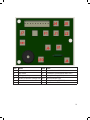
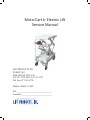
Moto-Cart Jr Electric Lift
Service Manual
LIFT PRODUCTS INC
PO BOX 349
ELM GROVE WI 53122
262-521-5720 FAX 262-521-5725
Toll Free 877-543-8776
Models: JRMC-11-ELT
S/N ________________________________
Customer____________________________
REGISTRATION INFORMATION
(To validate your warranty and receive updated service bulletins, please complete this form)
Date_______________
Model No.________________
How did you first hear of Lift Products?
____Magazine Ad (Specify which magazine)_____________________________________
____Recommended by a dealer (Name of Dealer)_________________________________
____Received information in the mail
____Internet
____Other (Please specify)___________________________________________________
What factors caused you to choose Lift Products?____________________________________
____________________________________________________________________________
____________________________________________________________________________
Describe how and where products are being used?____________________________________
____________________________________________________________________________
____________________________________________________________________________
Name of person completing this form______________________________________________
Title________________________________________________________________________
Company____________________________________________________________________
Street Address________________________________________________________________
City, State, Zip________________________________________________________________
Phone________________________ Fax No.________________________________________
Purchased From:
Name of Dealer_______________________________________________________________
Street Address________________________________________________________________
City, State, Zip________________________________________________________________
Phone No._____________________Fax No.________________________________________
Please fax this form to 262-521-5725.
It is important to read and follow all the instructions and safety information contained in the
Operation Manual prior to use.
We hope the carts will make your job easier and more fun. The Moto-Cart JR. can boost the
productivity in your organization and reduce injuries caused by repetitive pushing or pulling a
manual platform cart with heavy load. Therefore, you will create a safe working environment
and minimize the worker’s compensation insurance cost.
The cart is a battery power mobile platform truck used from moving materials, parts, or
machinery from one location to another without having to manually carry the load or push a
wheeled cart. These heavy push or pull cart applications can occur anywhere.
If these carts need constant pushing or pulling from one location to another and cause
fatigue to the employee moving the load, than it is a perfect application for our battery
powered, electric cart.
PACKING LIST
• (1) Folded Cart
• (8) M8x20 Screw
SPECIFICATIONS
•
•
•
•
Motor 24 volt/370 watts Battery 2x12 v/40 Ah sealed lead acid Battery
Battery Charger 100-220V-50/60Hz<1.5A AC/24VDC
Charge Time: 7 hours
Controlled Curtis 70A 24V
OPERATION
1. Turn ON Power
Insert the power key into the switch lock and turn clockwise to the “ON” position. All the
battery display lights should be on indicating the batteries are full and ready to work.
2. Check the Status
The status light should be on steadily if the electric and driving systems are OK. If it
flashes, check the clutch engagement first.
3. Forward Motion
Start your cart stand behind the tiller and hold the “bull-horns” with two hands. Look
straight ahead. Press the upward throttle lever by your two-hands four fingers slowly to
start moving forward. The speed should increase as you press more.
4. Stop Cart
Slowly releasing your four fingers from the throttle lever will reduce the speed and stop
the cart.
5. Emergency Stop
Just simply release your fingers quickly. The Cart should stop within 4.5 feet at full
forward speed.
Touch the Emergency stop button to stop the Trolley.
1
6. Reverse Motion
Press the downward throttle lever by your two-hands four fingers slowly to start moving
reverse.
7. Forward Steering
Look straight ahead. When you need to turn right, your turn the “Caster” to the left. Vise
a versa for the left turn.
Reverse Steering: The operation is the opposite as forward.
Move Manually (free wheeling):
Manual: You push or pull the Cart by disengaging the clutch in the transaxle.
Power: You can push or pull the Cart by pressing the free-wheel button by your right hand finger
and operating by your left hand.
WARNING: Before you operate, practice in a open area for at least one hour to get familiar with
the Cart and gain the operation skills. The brake may not be effective when engaged on inclines
greater than the grade with allowed load. Be alert!
EMERGENCY STOP
In case of out-of-control, turn the power off or pull safety button immediately.
SAFETY INSTRUCTIONS
We disclaim all responsibility for any personal injury or property damage, which may occur as a
result of improper or unsafe use of its products. The following guidelines are intended to assist
you in the safe operation of your cart. Should you have any questions about the correct operation of your Cart, please contact dealer.
Your cart can negotiate grass, gravel, dirt, and sand surfaces, as well as hard paved or carpeted
surfaces. However, extra caution should be taken when operating your unit on uneven surfaces
other than flat surfaces.
If unintended motion or brake release occurs, turn the power OFF as quickly as it is safe.
IN SUMMARY:
• DO NOT try to climb sharp curbs.
• DO NOT drive over obstacles exceeding 5cm in height.
• DO NOT make an abrupt change in high speed or while traveling on an incline.
• DO NOT attempt to make fast turn on flat surfaces.
• DO NOT climb inclines greater than 8° degrees or a rise of 2 meters in 10 meters.
• DO NOT back onto uneven surfaces or inclines.
• DO NOT attempt to operate your unit in a stalled condition, such as traveling up to steep
an incline. This may cause the circuit breaker or thermal cut out to trip, rendering your
unit temporarily immobile.
• DO NOT operate unit when the red battery indicator light is flashing.
2
BATTERY CHARGING
To ensure the best performance and maximum battery life, we recommend frequent battery
charging. Your Cart comes with an on-board battery charger for your ease and convenience. The
console battery display makes charging simple and easy. Follow these steps for battery charging.
1. The console battery display:
• Only when the battery is properly charged is the right-most green LED lit.
• As the battery’s state-of-charge decreases, successive LEDs light up, only one on at a
time.
• The 3rd-from-left red LED flashes, indicating “energy reserve” (70% depth of
discharge).
• The 3 left-most LEDs alternately flash, indicating “empty” (80% of depth of
discharge).
2. On a level dry surface, turn off the power key and plug the AC cord into the charger
socket located on the fiber-glass compartment. Plug the other end of the AC cord into a
grounded wall outlet.
3. Charge the battery for 6-8 hours depending on the usage before charging. Disconnect
the AC cord, insert key into tiller and check if all green lights are on.
4. There is no possible way to overcharge the battery since the charging voltage in
the floating stage is set constant. In general, you may start charging after work and
disconnect it in the next morning.
WARNING: You must turn off power before charging. Otherwise it may damage the electric
circuit.
3
MAINTENANCE SCHEDULE
In order to obtain the best performance and last its service lift, please maintain your unit according to the following schedule and instructions.
DAILY
1. Test brake effectiveness before you drive.
2. Recharge batteries fully every night.
WEEKLY
1. Check tire pressure. Pressure should be 40-50 psi.
2. Check and tighten the throttle screw.
MONTHLY
1. Check battery condition. Clean battery terminals if necessary.
2. Check all electrical wire connectors to eliminate loose connections.
3. Tighten all exposed screws and nuts.
4. Check wheel bearings by spinning tires and checking for free rotation.
THROTTLE ADJUSTMENT
1. Release the clutch lever, thus the motor can rotate freely.
2. Note on the throttle control potentiometer, when the control lever is swinging, how
the mount plate retain one end of the spring while the control bracket pulls the
other end of the spring in the direction of rotating. As the lever rotates in the opposite direction, the other spring end is pulled in the opposite direction.
3. With key in and speed setting at low, rotate the throttle lever until you just hear the
brake release click and motor starts running. Notice the angle rotated between the
lever and the Cart horn.
4. Rotate the throttle lever in the opposite direction till just brake releases clicks, notice
the angle rotated between the lever and the Cart horn in this direction.
5. If the angles are not identical, loosen control bracket screws, rotate potentiometer
shaft a few degrees by using a flat screw driver and then retighten it.
6. Repeat until the reverse, neutral, and forward are in proper ranges.
7. Make sure throttle control lever is parallel to tiller handle. If the lever is not parallel,
full range rotation in on direction will not be possible, resulting in loss of speed in
that direction.
4
5
6
7
8
9
Item
F1
J1
J2
J3
J4
J5
Name
Fuse
Key Switch
Emergency Stop
Power Accelerator (Orange Line)
Horn Switch
Horn
Item
J6
J7
BDI
LED
UI
Name
Electro-Mechanical Disk Brake
Accelerator Throttle (Black White Line)
Battery Fuel Gauge (o-5V)
Failure Indicator Light
Battery Fuel Gauge (DC24V)
10