1
ACCU-Master/ ACCU-Pro
AUTOMATIC
REEL MOWER GRINDER
with ACCU-Touch
ASSEMBLY
and
SERVICE
MANUAL
WARNING
You must thoroughly read and understand this
manual before assembling or maintaining the
equipment, paying particular attention to the
Warning & Safety instructions.
1
6527956 (4-06)
SAFETY INSTRUCTIONS
Safety Awareness Symbols are inserted into this manual
to alert you to possible Safety Hazards. Whenever you
see these symbols, follow their instructions.
The Warning Symbol identifies special instructions
or procedures which, if not correctly followed, could
result in personal injury.
The Caution Symbol identifies special instructions
or procedures which, if not strictly observed, could
result in damage to or destruction of equipment.
1. KEEP GUARDS IN PLACE and in working order. 12. DON'T OVERREACH. Keep proper footing and
balance at all times.
2. REMOVE WRENCHES AND OTHER TOOLS.
13. MAINTAIN GRINDER WITH CARE. Follow
3. KEEP WORK AREA CLEAN.
instructions in Service Manual for lubrication and
preventive maintenance.
4. DON'T USE IN DANGEROUS ENVIRONMENT.
Don't use Grinder in damp or wet locations.
14. DISCONNECT POWER BEFORE SERVICING,
Machine is for indoor use only. Keep work area
or when changing the grinding wheel.
well lit.
15. DO NOT USE SHARP OBJECTS ON THE
5. KEEP ALL VISITORS AWAY. All visitors should
TOUCH SCREEN. Do not clean the touch
be kept a safe distance from work area.
screen with solvents.
6. MAKE WORK AREA CHILD-PROOF with
padlocks or master switches.
7. DON'T FORCE THE GRINDER. It will do the
job better and safer if used as specified in this
manual.
8. USE THE RIGHT TOOL. Don't force the Grinder
or an attachment to do a job for which it was not
designed.
9. WEAR PROPER APPAREL. Wear no loose
clothing, gloves, neckties, or jewelry which may
get caught in moving parts. Nonslip footwear is
recommended. Wear protective hair covering to
contain long hair.
10. ALWAYS USE SAFETY GLASSES.
11. SECURE YOUR WORK. Make certain that the
cutting unit is securely fastened with the clamps
provided before operating.
16. USE RECOMMENDED ACCESSORIES. Consult
the manual for recommended accessories. Using
improper accessories may cause risk of personal
injury.
17. CHECK DAMAGED PARTS. A guard or other
part that is damaged or will not perform its intended
function should be properly repaired or replaced.
18. KNOW YOUR EQUIPMENT. Read this manual
carefully. Learn its application and limitations as
well as specific potential hazards.
19. KEEP ALL SAFETY DECALS CLEAN AND
LEGIBLE. If safety decals become damaged or
illegible for any reason, replace immediately. Refer
to replacement parts illustrations in Service Manual
for the proper location and part numbers of safety
decals.
20. DO NOT OPERATE THE GRINDER WHEN UNDER
THE INFLUENCE OF DRUGS, ALCOHOL, OR
MEDICATION.
2
SAFETY INSTRUCTIONS
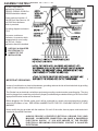
IMPROPER USE OF GRINDING WHEEL MAY CAUSE
BREAKAGE AND SERIOUS INJURY.
Grinding is a safe operation if the few basic rules listed below are followed. These
rules are based on material contained in the ANSI B7.1 Safety Code for "Use, Care
and Protection of Abrasive Wheels". For your safety, we suggest you benefit from
the experience of others and carefully follow these rules.
DO
DON'T
1. DO always HANDLE AND STORE wheels in a
CAREFUL manner.
1. DON'T use a cracked wheel or one that HAS
BEEN DROPPED or has become damaged.
2. DO VISUALLY INSPECT all wheels before
mounting for possible damage.
2. DON'T FORCE a wheel onto the machine OR
ALTER the size of the mounting hole - if
wheel won't fit the machine, get one that will.
3. DO CHECK MACHINE SPEED against the
established maximum safe operating speed
marked on wheel.
3. DON'T ever EXCEED MAXIMUM
OPERATING SPEED established for the
wheel.
4. DO CHECK MOUNTING FLANGES for equal
and correct diameter.
4. DON'T use mounting flanges on which the
bearing surfaces ARE NOT CLEAN, FLAT
AND FREE OF BURRS.
5. DO USE MOUNTING BLOTTERS when
supplied with wheels.
5. DON'T TIGHTEN the mounting nut
excessively.
6. DO be sure WORK REST is properly adjusted.
6. DON'T grind on the SIDE OF THE WHEEL
(see Safety Code B7.2 for exception).
7. DO always USE A SAFETY GUARD
COVERING at least one-half of the grinding
wheel.
7. DON'T start the machine until the WHEEL
GUARD IS IN PLACE.
8. DO allow NEWLY MOUNTED WHEELS to run
at operating speed, with guard in place, for at
least one minute before grinding.
8. DON'T JAM work into the wheel.
9. DON'T STAND DIRECTLY IN FRONT of a
grinding wheel whenever a grinder is started.
9. DO always WEAR SAFETY GLASSES or some
type of eye protection when grinding.
10. DON'T FORCE GRINDING so that motor
slows noticeably or work gets hot.
AVOID INHALATION OF DUST generated by grinding and cutting operations.
Exposure to dust may cause respiratory ailments. Use approved NIOSH or
MSHA respirators, safety glasses or face shields, and protective clothing.
Provide adequate ventilation to eliminate dust, or to maintain dust level below
the Threshold Limit Value for nuisance dust as classified by OSHA.
3
This machine is intended for grinding the reel of reel type mower units ONLY.
Any use other than this may cause personal injury and void the warranty.
To assure the quality and safety of your machine and to maintain the
warranty, you MUST use original equipment manufactures replacement
parts and have any repair work done by a qualified professional.
ALL operators of this equipment must be thoroughly trained BEFORE
operating the equipment.
Do not use compressed air to clean grinding dust from the machine. This
dust can cause personal injury as well as damage to the grinder. Machine
is for indoor use only. Do not use a power washer to clean the machine.
Low Voltage Relay
The grinder is equipped with a low voltage relay which
is factory preset at 100 VAC. If the power supply line
does not deliver 100 VAC power under load, the relay
will open and trip out the starter. If this occurs, your
power supply line is inadequate and must be correct
before proceeding further with the grinder.
CONTENTS
Safety Warnings .................................................................................................................. Page 2-4
Service Data ........................................................................................................................ Page 5
Assembly Instructions ......................................................................................................... Page 6-10
Maintenance Instructions .................................................................................................... Page 11-14
Adjustments ........................................................................................................................ Page 15-24
Machine Service .................................................................................................................. Page 25-26
Electrical Troubleshooting Index . ........................................................................................ Page 28
Electrical Troubleshooting ................................................................................................... Page 29-48
Mechanical Troubleshooting ................................................................................................ Page 50-51
Parts Lists ........................................................................................................................... Page 52-89
Electrical Diagrams ............................................................................................................. Page 90-97
-Separate Drawings Included in the Product Packet
4
SERVICE DATA
SKILL AND TRAINING REQUIRED FOR SERVICING
This Service Manual is designed for technicians who have the necessary mechanical and
electrical knowledge and skills to reliably test and repair the ACCU-Pro or ACCU-Master Grinder.
For those without that background, service can be arranged through your local distributor.
This Manual presumes that you are already familiar with the normal operation of the Grinder. If
not, you should read the Operators Manual, or do the servicing in conjunction with someone
who is familiar with its operation.
Persons without the necessary knowledge and skills should not remove the control box cover
or attempt any internal troubleshooting, adjustments, or parts replacement.
If you have questions not answered in this manual, please call your distributor. They will
contact the manufacturer if necessary.
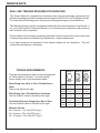
TORQUE REQUIREMENTS
GRADE 2
Throughout this manual we refer to torque requirements
as "firmly tighten" or the like. For more specific
torque values, refer to the information below.
Bolts Going Into a Nut, or Into a Thread Hole in
Steel
Refer to the table at the right.
Bolts Going Into a Thread Hole in Aluminum
Use the Grade 2 values in the table at the right.
SMOOTH
HEAD
3 MARKS
on HEAD
1/4 In.
thread
6 ft-lbs
(0.8 kg-m)
9 ft-lbs
(1.25 kg-m)
13 ft-lbs
(1.8 kg-m)
5/16 In.
thread
11 ft-lbs
(1.5 kg-m)
18 ft-lbs
(2.5 kg-m)
28 ft-lbs
(3.9 kg-m)
31 ft-lbs
(4.3 kg-m)
46 ft-lbs
(6.4 kg-m)
75 ft-lbs
(10.4 kg-m)
3/8 In.
thread
Socket-Head Screws Going Into a Nut or Steel
Use the Grade 8 values in the table at the right.
Machine Screws
No. 6 screws: 11 in.-lbs (0.125 kg-m)
No. 8 screws: 20 in.-lbs (0.23 kg-m)
No. 10 screws: 32 in.-lbs (0.37 kg-m)
5
GRADE 5 GRADE 8
19 ft-lbs
(2.6 kg-m)
6 MARKS
on HEAD
7/16 In.
thread
30 ft-lbs
(4.1 kg-m)
50 ft-lbs
(6.9 kg-m)
1/2 In.
thread
45 ft-lbs
(6.2 kg-m)
75 ft-lbs
115 ft-lbs
(10.4 kg-m) (15.9 kg-m)
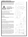
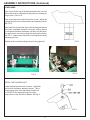
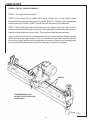
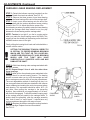
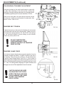
ASSEMBLY INSTRUCTIONS
Remove the sides, front, and back of the crate. Remove
the plastic bag, shrink wrap and bubble wrap around
control panel. Remove the metal clips that secure the
grinder to the wood base. With a fork lift, raise the grinder
from the wood base and set it in its final position. See FIG.
1 and 2.
THE UNIT WEIGHS
1500 - 2000 LBS. [680-907 kg]
TO LIFT, USE POWER
EQUIPMENT.
Remove shipping straps from traverse carriage.
Remove window protective sheets.
[652 ACCU-Master (Boom Model)]
The winch boom is held in place during shipping with a
steel brace. Remove and discard this brace. Remove
the shrink wrap and cable tie that holds the winch trolley
to the beam.
652
[Lift Models]
Remove and discard the bolt used to hold the ramp up
for shipping before using rear lift.
FIG. 1
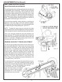
POSITION BASE
The base should be placed on a relatively level concrete
floor, with ample ceiling height to allow for the installation of
the unit. Do not place the unit across two concrete slab
seams or across a large crack.
The 632 ACCU-Pro Spin/Relief Grinder will require an
operating area of about 150" W x 108" D x 87" H (381 x
274 x 221 cm). The mower reel will be lifted from the
front of the machine if using the boom and the rear if a lift
is installed. The machine operator will operate the unit
from the front of the machine.
Position the base to
allow sufficient operating room in front of the machine
(and behind if using the rear lift). See FIG. 2.
632
The 652 ACCU-Master will require an operating area of
about 150" W x 108" D x 87" H [381 x 274 x 221 cm].
The reel mower assembly will be lifted from the front of
the machine if using the boom and the rear if a lift is
installed. The machine operator will operate the unit from
this same position. Position the base to allow sufficient
operating room in front of the machine. See FIG. 1.
FIG. 2
6
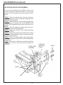
ASSEMBLY INSTRUCTIONS (Continued)
Remove the carton and remove the contents from the carton
onto a workbench. The carton includes:
SPREADER BAR ASSEMBLY
(ONLY ON MODELS WITH BOOM)
PRODUCT
PACKET
SPIN DRIVE
ADAPTER
5" (127mm) DIA. X 3/8" (10mm)
WIDE GRINDING WHEEL
3.5" (89mm) DIA. X 1" (25mm)
WIDE GRINDING WHEEL
3.5" (897mm) DIA. X 3/8" (10mm)
WIDE GRINDING WHEEL
ALIGNMENT GAGE
ALLEN WRENCH
REEL POSITION GAGE
FLASHER BULB
& LENS
HORIZONTAL EXTENSION
(ALIGNMENT GAGE)
DRIP PAN
7
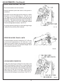
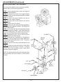
ASSEMBLY INSTRUCTIONS (Continued)
LEVEL BASE
Place a level on the top of the table and check the unit from
side to side for level. Adjust the leveling feet as necessary to
bring to level. See FIG. 4.
Place a level across the table from front to rear. Adjust the
leveling feet on the end of the machine as necessary to level.
See FIG. 5.
When both front to back and side to side leveling procedures
have been completed, thread the hex jam nuts up against
the nut that is welded to the bottom until they lock into place.
Be careful not to move the leveling feet during this process.
See FIG. 3. Make certain that all four leveling feet are firmly
contacting the floor.
Recheck with level after locking nuts are firmly tightened.
2-1/4" [57 mm]
FIG. 3
FIG. 5
FIG. 4
INSTALL THE FLASHER LIGHT
Locate flasher bulb and lense in carton. Install bulb
and lense to the flasher assembly socket. This is
located ontop of the front right frame member on
the 632 ACCU-Pro and on the top of the right
canopy door for the 652 ACCU-Master. See Fig. 6.
FIG. 6
8
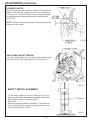
ASSEMBLY INSTRUCTIONS (Continued)
APPLY POWER
BEFORE YOU APPLY POWER TO THE
GRINDER, REFER TO THE "IMPORTANT
GROUNDING INSTRUCTIONS" ON PAGE 10.
115 Volt Model Only. Plug the power cord into a standard 115V
AC 20-amp grounded receptacle. See FIG. 7.
FIG. 7
220 Volt Model Only. For 220 Volt Applications order Part No.
6320935, 6320945, 6520915, or 6520925, which includes a
prewired 3 KVA 220 V step down to 110 V 50-60 Hz
transformer should be ordered.
IT IS RECOMMENDED THAT THIS
ACCU-MASTER REEL MOWER GRINDER HAS
ITS OWN PERMANENT POWER CONNECTION
FROM THE POWER DISTRIBUTION PANEL,
WITH NO OTHER MAJOR POWER DRAW
EQUIPMENT ON THE SAME LINE.
IT IS REQUIRED THAT THE POWER
DELIVERED TO THIS GRINDER IS
115 VAC - 20 AMPS. THE TOLERANCE ON THIS
POWER REQUIREMENT IS +/- 5%.
THEREFORE THE MINIMUM VOLTAGE
REQUIREMENT IS 109VAC WITH 20 AMPS.
VOLTAGE MUST BE CHECKED WITH ALL
EQUIPMENT UNDER LOAD (OPERATING) ON
THE CIRCUIT.
The grinder is equipped with a low voltage relay
which is factory preset at 100 VAC. If the power
supply line does not deliver 100 VAC power under
load, the relay will open and trip out the starter. If
this occurs, your power supply line is inadequate
and must be corrected before proceeding further
with the grinder.
DO NOT OPERATE THIS GRINDER WITH
AN EXTENSION CORD.
PROPER GROUNDING OF THE RECEPTACLE
GROUND IN YOUR BUILDING MUST BE
VERIFIED. IMPROPER GROUNDING IN
YOUR BUILDING MAY CAUSE THE GRINDER
TO MALFUNCTION.
FOR 20 AMP RATED LARGE MACHINES
Below is a list of required wire size in your building. (This is the
wiring from the main panel to the grinder receptacle box.)
For 0 to 40 Feet from panel to receptacle = Use 12 Ga. Wire.
For 40 to 60 Feet from panel to receptacle = Use 10 Ga. Wire.
For 60 to 100 Feet from panel to receptacle = Use 8 Ga. Wire.
For 100 to 160 Feet from panel to receptacle = Use 6 Ga. Wire.
For 0 to 12 Meters from panel to receptacle = Use 4.0mm Wire.
For 12 to 18 Meters from panel to receptacle = Use 6.0mm Wire.
For 18 to 30 Meters from panel to receptacle = Use 10.0mm Wire.
For 30 to 48 Meters from panel to receptacle = Use 16.0mm Wire.
9
ASSEMBLY INSTRUCTIONS (Continued)
For 220 V 50 or 60Hz
applications Product No.
6320935, 6320945, 6520915 or
6520925 should be ordered.
These products includes a 3
KVA 220 Volt Step Down to 110
volt 50/60 Hz transformer
which is prewired.
The wiring diagram is shown in
FIG. 8.
The power cord has no
connector. A connector which
is appropriate for your locality
and 220 volt, 10 amp
application should be installed.
USE ONLY A QUALIFIED
ELECTRICIAN TO
COMPLETE THE
INSTALLATION.
FIG. 8
IMPORTANT GROUNDING INSTRUCTIONS
In case of a malfunction or electrical breakdown, grounding reduces the risk of electrical shock by providing
a path of least resistance for electrical current.
This Grinder has an electrical cord with an equipment grounding conductor and a grounding plug. The plug
must be plugged into a matching outlet that is properly installed and grounded according to all local or other
appropriate electrical codes and ordinances.
Before plugging in the Grinder, make sure it will be connected to a supply circuit protected by a properly
sized circuit breaker or fuse. SEE SERIAL NUMBER PLATE FOR FULL LOAD AMP RATING OF YOUR
MACHINE.
Never modify the plug provided with the machine--if it won't fit the outlet, have a proper outlet and circuit
installed by a qualified electrician.
ALWAYS PROVIDE A PROPER ELECTRICAL GROUND FOR YOUR
MACHINE. AN IMPROPER CONNECTION CAN CAUSE A DANGEROUS
ELECTRICAL SHOCK. IF YOU ARE UNSURE OF THE PROPER
ELECTRICAL GROUNDING PROCEDURE, CONTACT A QUALIFIED
ELECTRICIAN.
10
PERIODIC MAINTENANCE
DAILY MAINTENANCE IS SPECIFIED ON PAGE 4 OF THE OPERATOR'S MANUAL, AND IS TO
BE PERFORMED BY THE OPERATOR.
LISTED BELOW ARE PERIODIC MAINTENANCE ITEMS TO BE PERFORMED BY YOUR
COMPANY'S MAINTENANCE DEPARTMENT:
1. Clean the tank and filter of the vacuum system weekly
or more often depending on the number of reels
ground. (VACUUM SYSTEM IS OPTIONAL
EQUIPMENT ALL 632 ACCU-PRO MODELS).
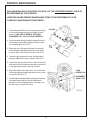
2. Use the grease fitting provided to grease the dove
tail with high quality lithium grease monthly. Wipe
off excess grease. See FIG. 9.
3. Wipe and re-oil with spray lubricant, the grinding
wheel diameter adjusting lead screw every three
months. Wipe off all excess lubricant. See FIG. 9.
4 Check the gib adjustment on the Grinding wheel
diameter adjustment every 3 months. See FIG. 9.
FIG. 9
5. Inspect the Grinding wheel Poly-V belt for cracking
and adjust the belt tension per procedure called out
in the adjustment section every six months.
6. Wipe and relube with never-seez, the vertical and
horizontal alignment shafts and lead screws, every
six months. See FIG. 10.
7. Lift the bellows and wipe off the bearing rails monthly.
Lubricate linear bearing, follow the lubrication
procedure on the following pages. Generally, this
will be every six months to a year.
LEAD
SCREW (2X)
ALIGNMENT
SHAFT (2X)
FIG. 10
11
STORAGE PROCEDURE
It is important to follow the procedures below when placing your grinding in storage for an
extended period of time. Proper care will help maintain the working functions of the grinder and
decrease maintenance and problems that occur when storing the grinder.
BEFORE STORING THE GRINDER:
-Clean the machine thoroughly. (DO NOT USE COMPRESSED AIR OR A POWER WASHER
TO CLEAN THIS MACHINE!) See Maintenance section for instructions on cleaning
polycarbonate.
-Lubricate the following parts by flooding the area with a spray lubricant and leaving it in
place: (Do not use a Teflon based lubricant)
Traverse Shafts & Linear bearings (see Lubrication section of manual)
Remove grinding wheel and spray the movable parts of the finger system
Cross slide shafts and adjustment screws (Right side of Traverse Base)
Scratches in the paint or any other bare metal surfaces
-Work the lubricant in by moving parts through their full range of motion.
-Make sure all controls are in the off position and unplug the unit from the wall. Turn off the digital
alignment gage.
-Cover the unit if possible with a sheet or tarp.
BRINGING THE UNIT BACK INTO SERVICE:
-Remove the cover and reapply lubricant to the items stated above. Wipe off all excess lubricant.
(See Lubrication section for more details.)
-Plug the unit into the wall and test all electrical functions.
-Check the belts for cracking and adjust the tension if necessary.
-Check for damaged or missing parts.
12
LUBRICATION
LUBRICATION OF LINEAR BEARINGS
STEP 1--Thoroughly clean the shafts.
STEP 2--Flood spray the two shafts with a spray lubricant (do not use a teflon based
lubricant) until the lubricant is dripping off the shafts. See FIG. 11 Then run the carriage back
and forth through its range of travel. This will carry the lubricant into the bearings.
STEP 3--With a clean rag, wipe off the excess amount of lubricant from the shafts. Run the
carriage back and forth through its range of travel and wipe the shafts after each traverse.
Repeat until the shafts are dry to the feel. This completes the lubrication process.
If the unit will be shut down for an extended period of time, more than four weeks, then the
shafts and other appropriate parts of the unit should be flooded with lubricant and that
lubricant left in place until the unit is brought back into service. When the unit is brought back
into service the full lubrication procedure as stated above should be repeated.
SHAFTS
TRAVERSE BASE ALONE
WITHOUT DUST PROTECTION
COMPONENTS
FIG. 11
13
MAINTENANCE (Continued)
CLEANING AND MAINTENANCE GUIDELINES FOR POLYCARBONATE
WINDOWS
Cleaning Instructions
DO NOT USE GASOLINE
Adherence to regular and proper
cleaning procedures is recommended
to preserve appearance and performance.
Washing to Minimize Scratching
Wash polycarbonate windows with a mild dish washing liquid detergent and lukewarm water, using a clean
soft sponge or a soft cloth. Rinse well with clean water. Dry thoroughly with a moist cellulose sponge to
prevent water spots. Do not scrub or use brushes on these windows. Also, do not use butyl cellosolve in
direct sunlight.
Fresh paint splashes and grease can be removed easily before drying by rubbing lightly with a good
grade of VM&P naphtha or isopropyl alcohol. Afterward, a warm final wash should be made, using a mild
dish washing liquid detergent solution and ending with a thorough rinsing with clean water.
Minimizing Hairline Scratches
Scratches and minor abrasions can be minimized by using a mild automobile polish. Three such
products that tend to polish and fill scratches are Johnson paste Wax, Novus Plastic Polish #1 and #2,
and Mirror Glaze plastic polish (M.G. M10). It is suggested that a test be made on a corner of the
polycarbonate window with the product selected following the polish manufacturer's instructions.
Some Important "DON'TS"
¨ DO NOT use abrasive or highly alkaline cleaners on the polycarbonate windows.
¨ Never scrape polycarbonate windows with squeegees, razor blades or other sharp
instruments.
Benzene, gasoline, acetone or carbon tetrachloride should NEVER be used on polycarbonate
windows.
¨ DO NOT clean polycarbonate windows in hot sun or at elevated temperatures.
Graffiti Removal
• Butyl cellosolve, (for removal of paints, marking pen inks, lipstick, etc.)
• The use of masking tape, adhesive tape or lint removal tools works well for lifting off old
weathered paints.
• To remove labels, stickers, etc., the use of kerosene, VM&P naphtha or petroleum spirits is
generally effective. When the solvent will not penetrate sticker material, apply heat (hair
dryer) to soften the adhesive and promote removal.
GASOLINE SHOULD NOT BE USED!
14
MAINTENANCE (Continued)
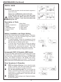
DIGITAL GAGE
Important
¨
¨
¨
Do not mark the scale unit with and electric engraver or
scratch the scale.
Always use an SR44 battery (silver oxide cell)
If the scale will not be used for more than three
months, remove the battery and store it properly.
Otherwise, leakage, if any, from the battery may
damage the unit.
Description of Parts
1. Beam
3. Battery compartment
5. Display
7. ZERO/ABS switch
9. Inch/mm Switch
11. Slider
2. Main Scale
4. Output Connection
6. ON/OFF Power
8. Origin Switch
10. Tapped hole
Battery Installation and Origin Setting
Set the origin of the scale after installing the battery. Otherwise,
the error sign("E" at the least significant digit) may appear,
resulting in incorrect measurements.
1)
To install the battery, remove the compartment lid and
install the SR44 battery with its positive side facing up.
After the battery is installed, set the origin.
2)
To set the origin, move the slider to an area you wish to
set as your origin. Turn the power on. Hold the ORIGIN
switch down for more than one second. The "0.00"
display appears, indication Origin setting is complete. The
origin will be retained even if the power is turned off.
Incremental (INC) & Absolute (ABS) mode
The LCD will dispay measurements from the origin when turned
on (ABS mode). To set the origin see above. The display can be
set to zero at any desired position by pressing the ZERO/ABS
switch. INC indicator will apper in the display (INC mode),
permitting measurements from this zero point. To return to the
ABS mode hole the ZERO/ABS buttton for more than 2 seconds.
Error Symptoms & Remedies
ERRC and display flickering: Occurs when the scale
surface is stained. Clean the scale surface and coat a
thin film of low viscosity oil to keep out moisture.
E in the least significant digit: This occurs when the
slider is moved too quickly, but it does not affect the
measurement. If it stays on when the slider stops, the
scale surface is probably stained. If this is the case, take
remedies as for ErrC.
B indication: Battery voltage is low. Replace the battery
as soon as possible.
15
ADJUSTMENTS (Continued)
CARRIAGE LINEAR BEARING REPLACEMENT
STEP 1--Detach the bellows mounting brackets from the
carriage. Detach front and rear shields. See FIG. 15.
STEP 2--Remove the three screws of one linear bearing
and slide the linear bearing off the end of the carriage shaft.
STEP 3--Insert a new linear bearing onto the end of the
carriage shaft with the tension adjustment screw pointing
outward. See FIG. 14. Adjust the tension screw of the
linear bearing so when you radially rotate the linear bearing
around the carriage shaft there should be no free play
between the linear bearing and the carriage shaft.
NOTE: Tension is too tight if you feel a cogging action
when you rotate the linear bearing around the shaft. This
cogging is from the skidding of the bearing on the shaft and
indicates tension screw is too tight.
Finally, sliding the bearing block back and forth should be a
smooth uniform motion.
FIG. 14
SETTING THE BEARING TENSION CORRECTLY
IS CRITICAL TO PROPER GRINDING. BEARINGS
WHICH ARE TOO TIGHT OR TOO LOOSE WILL
CAUSE POOR GRIND QUALITY. ALSO, BEARINGS
WHICH ARE TOO TIGHT WILL HAVE
SUBSTANTIALLY SHORTER LIVES AND MAY
DAMAGE THE SHAFT.
STEP 4--Slide linear bearing under carriage and attach with
the three screws.
NOTE: Repeat Steps 2 thru 4 with the other three
linear bearings.
STEP 5--After all four linear bearings are reattached to the
carriage check for correct bearing tension. The bearing
tension is correct when you try to lift the carriage and can
feel no carriage movement, which is free play up and down.
The most dependable method of checking free play is to
use a magnetic base dial indicator attached to the traverse
frame weldment and reading the vertical movement above
each bearing. This movement should be within .001" (.03
mm) Also, when pulling the carriage in the traversing
direction, there should be only approximately a 3 lb force,
with the belt disengaged. To check this attach a spring scale
to the carriage and pull parallel to the carriage shafts. To
double check the assembly, slide the carriage assembly
from "end of travel" to "end of travel", it should have very
uniform resistance through the full range of travel.
STEP 6--Replace the bellows carriage mounting brackets
onto the carriage. Replace front and rear shields.
See FIG. 15.
16
FRONT DUST
SHIELD
REAR DUST
SHIELD
FIG. 15
ADJUSTMENTS (Continued)
REEL FINGER DOVETAIL GIB AND
ADJUSTING KNOB ADJUSTMENTS
The reel finger slide to the reel finger positioner has a dovetail with
an adjustable gib for tensioning. Tighten the gib set screws
on the side so there is no free play in the dovetail slide. Check
for movement when pushing on the relief finger side to side
with a 20 lbs. (44 kg) force. Make sure the knob assembly for
adjusting the relief finger to the grinding wheel is rotatable by
hand. The gib adjustment should be sufficient to maintain a
rigid position of the reel finger. See FIG. 16.
Check the knob assembly rotating tension by checking the
tightness of the nylon plug to the knob assembly threads.
The tightness has to be sufficient so the knob assembly does
not rotate during the relief grinding cycle. See FIG. 17.
FIG. 16
NOTE: To adjust the nylon plug you must lock the index
finger assembly down and then adjust the reel finger positioner
so the clearance holes line up with the nylon plug set screw.
Take up any free play between the tee knob assembly, reel
finger slide and .375 threaded split shaft collar. Loosen the
shaft collar locking cap screw and rotate the shaft collar until
there is no end play. Retighten locking cap screw on the
threaded split shaft collar. See FIG. 16.
GRINDING HEAD BELT TENSION ADJUSTMENT
The left side grip grinding wheel knob must be removed for
belt tensioning adjustment. Remove the six screws holding
the vacuum hose bracket, the two double tube clamps and
the belt cover. For grinding motor belt adjustment, loosen
the four socket head cap screws that attach the motor
mounting plate. Adjust the grinding motor for proper belt
tension and tighten the four socket head cap screws. The
proper belt tension for the grinding head is to push down on
the poly V belt half way between to two pulleys with
5 lbs. [2 kg] of force and belt movement dimensions to be
.12 inches [3 mm]. See FIG. 18.
To verify belt tension mount the belt guard with two screws.
Turn the motor on. If the belt is tensioned correctly, start-up
torque of the motor through the pulley to the belt should have
zero slippage. If there is belt slippage when turning
on the motor there will be a slight squeal
before the belt comes up to speed.
When you achieve correct tension,
reassemble all of the remaining
parts that have been removed.
FIG. 17
.12 [3 mm]
FIG. 18
17
ADJUSTMENTS (Continued)
INDEX FINGER PROXIMITY SETTING
Set all motor switches to the off position.
Press the machine system start switch, so the grinder is
operational.
Push down on the index finger until the stop pin is within
.06 inches (1.5 mm) of bottoming out. (You can use a
1/16" gage pin or rod stock between the stop pin and
index finger). Set the proximity switch to activate the light at
this setting. This assures the index finger to be close to
its final stop position so the reel is completely indexed
before the carriage starts to traverse. See FIG. 19.
The spring load force pushing up on the index finger brings
it away from the proximity when released.
FIG. 19
STEPPPER INFEED TRAVEL LIMITS
The infeed stepper maximum extension is 6.0" (152 mm)
and minimum compression is 3.5" (89 mm). If you
experience a situation where the grind does not properly
finish, check that you have not exceeded stepper travel
by checking the values per FIG. 20.
FIG. 20
LOCKING INDEX FINGER PIN
To align the Index Finger Locking Pin to the hole in the
Index Finger Assembly loosen the two socket head cap
screws so the index sensor block is movable. Push down
on the index finger assembly until the spring loaded index
finger locks into hole with no binding. Tighten the two
socket head cap screws so the index sensor block is
secured, and the locking pin moves freely. See FIG. 21.
FIG. 21
18
ADJUSTMENTS (Continued)
PROXIMITY SWITCH
For the proximity switch to perform properly and reverse the
direction of the carriage at each end of the rails, a distance of
3/16" [4 mm] to 1/4" [6 mm] needs to be maintained between
the carriage proximity flag bracket and the proximity switch.
See FIG. 22.
NOTE: The light on the proximity switch activates when metal
crosses over the switch.
FIG. 22
ADJUSTABLE RELIEF TENSION
If the relief angle appears to vary during relief grinding adjust
the tension on the nylon plug and set screw. See FIG. 23.
FIG. 23
SAFETY SWITCH ALIGNMENT
For the safety switches to work properly they must be
adjusted so the sender and receiver are parallel to each other
with a maximum gap of .19 inches (5mm).
See FIG. 24.
(Adjust by moving the doors or brackers. If this does not
help, a special wrench is needed to adjust the safety screws
used to hold the switch in place.)
.19" (5mm)
FIG. 24
19
ADJUSTMENTS (Continued)
SPIN GRINDING ATTACHMENT ADJUSTMENT
If free play develops so the crank handle wants to rotate with
free play when operating in the scissor action (raising and
lowering) on the spin grinding attachment, the free play can be
eliminated by tightening the set screw identified in FIG. 24.
If there is too much play in the spin drive pivot points, torque
down the hex nut tight so conical washer is compressed, then
back off 1/2 turn. See FIG. 24.
TRAVERSE BELT TENSION
FIG. 24
To adjust the tension on the traverse belt tighten the screws and
nuts located at the left side of the traverse belt. Tighten nuts until
the comprension springs measure 3/4". See FIG. 25. If the springs
are not tensioned equally, uneven loading on the traverse
system may cause parts to fail.
DO NOT OVERTIGHTEN.
OVERTIGHTENING COULD
DAMAGE THE BELT OR TRAVERSE
DRIVE SYSTEM.
TRAVERSE CLAMP FORCE
If the traverse clamp is slipping during regular operation it may be
necessary to tighten the clamp. To tighten, loosen the jam nut on
the clamp tip. Screw the tip out so there is .10" gap between the
tip and the Clamp Support Block. See FIG 26. Lock in place by
tightening the jam nut against the clamp being careful not to move
the tip. Verify the distance between the clamp tip and block is still
.10". The .10" setting allows slippage in a jam situation and
FIG. 25
damage can occur if this adjustment is set to narrow.
CAUTION SHOULD BE USED
AS ADJUSTING THE TIP WILL
AFFECT THE SLIP LOAD AND
COULD DAMAGE THE CLAMP
TIP, BELT OR TRAVERSE
DRIVE SYSTEM.
FIG. 26
20
ADJUSTMENTS (Continued)
ADJUSTING CROSS SLIDE ASSEMBLY
If the cross slide becomes very difficult to turn it may
become necessary to adjust the assembly. To relieve the
tension on the assembly follow the procedure listed
below:
STEP 1--Using a hydraulic jack, raise the traversing
carriage base just enough to alleviate the weight stress on
the Cross Slide Assembly.
STEP 2--Knock out the pins on either side of the Mounting
Frame Adjuster and loosen the 4 bolts (B504801) that
connect the Carriage Mounting Frame to the frame of the
grinder.
STEP 3--Jack the traversing carriage base up to put a
preload on the Cross Slide Assembly.
STEP 4--Tighten the 4 bolts on the Carriage Mounting
Frame to 75 ft-lbs.
STEP 5--Release the jack pressure and test the vertical
and horizontal handwheels for ease of movement through
their full range of motion.
STEP 6--If the Cross Slides tend to bind, repeat above
steps jacking higher or lower (STEP 1) until the handwheels
move freely.
STEP 7--When the Cross Slides move freely through their
full range of motion, drill new holes and repin the
assembly.
CROSS SLIDE
ASSEMBLY
CARRIAGE
MOUNTING
FRAME
BOLTS
PIN
BOLTS
PART OF
FRAME
PIN
21
ADJUSTMENTS (Continued)
CROSS SLIDE SHAFT REPLACEMENT
If the cross slide shafts become scarred or gnarled,
replace them by the following procedure:
STEP 1--Use a hydraulic jack to raise the weight off
the Cross Slide Assembly.
STEP 2--Loosen the two nuts on the support casting
that hold the locking stud and tap with plastic or rubber
hammer to loosen.
STEP 3--Loosen the locking handles and tap the
center stud with a plastic hammer.
STEP 4--Loosen locknut and setscrew and remove
the handwheel.
STEP 5--Remove the Slide Shaft.
STEP 6--Remove all burrs and resurface the shaft to
a clean, smooth, polished surface. (OR REPLACE
WITH A NEW SHAFT.)
STEP 7--Coat shaft with Never-Cease and re-install
the shaft through the Support, Cross Slide Block and
the three locking studs. The shaft must move freely
inside the Cross Slide Block before reassembling.
STEP 8--Retightening the nuts at the end of the
locking studs to lock shaft in place.
STEP 9--Reinstall the Handwheel by snugging the
setscrew to the flat located on the screw shaft, then
torque nut until tight and back off 1/2 turn. Torque the
setscrew to 70 in-lbs.
STEP 10--Test the Cross Slide, the handwheel should
turn freely.
STEP 11--Lower the jack and retest the Cross Slide
Assembly through full range of motion. If binding
occurs, follow the procedure under Cross Slide
Assembly located on page 21.
LOCKNUT
CROSS
SLIDE
LOCK
HANDLES
NOTE: It is also possible to remove the complete Cross
Slide Assembly and do the repairs on a bench then
reinstall.
NUT
DUTCHMAN
SLIDE
SHAFTS
LOCKNUT
SETSCREW
HANDWHEEL
22
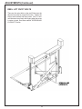
ADJUSTMENTS (Continued)
REEL LIFT PIVOT BOLTS
There are four pivot bolts on the reel lift that must be
adjusted correctly for proper lift function. Tighten the
screws and locknuts and then loosen 1/8 to 1/4 turn
until the screw turns freely with fingers when the screw
is under no load. See items marked "SCREWS AND
LOCKNUTS" below.
23
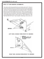
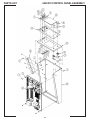
ADJUSTMENTS (Continued)
REEL LIFT SIDE BEARING ASSEMBLIES
There are four side bearing assemblies (two on each side) on the reel lift. The two on
the right side looking from the front of the grinder are fixed with screws and washers.
The two on the left side looking from the front of the grinder are spring loaded against
the lift frame. They must be adjusted correctly for proper lift function. These left side
screws can be accessed through two holes on the inside of the vacuum chamber.
Remove the vacuum cover and take out the vacuum. There are two plastic plugs on
the back wall of the vacuum chamber. Remove these plugs and raise or lower the lift
until the spring retainer screws line up with the holes. Tighten the screws until tight
(springs solid) with blue loctite no. 242, then back the scres out ONE full turn. See
items marke "B311613" below. When complete, reinstall plugs, vacuum and cover.
LEFT SIDE LOOKING FROM FRONT OF GRINDER
RIGHT SIDE LOOKING FROM FRONT OF GRINDER
24
CONTROL BOARD POTENTIOMETER ADJUSTMENTS
SPIN DRIVE CONTROL BOARD (SDC)
The Spin Drive Control Board has three potentiometers on the lower board and two potentiometers on the
upper board as shown on drawing 6524511 which is included. These potentiometers have been set at the
factory to the positions shown on the drawing. Also see FIG. 27A and 27B.
In the Relief Grinding Mode--The Remote Speed Pot and the Relief Torque Pot (RTP) interact with each other. The remote speed pot is
located on the upper board of the Spin Drive Control (SDC) preset at 9:30. The (RTP) is located on the control
panel and is for relief torque adjustment. See FIG. 27B.
The Remote Speed Pot when rotated clockwise will increase maximum spin drive speed. The remote speed
pot should never be above the 10:30 setting.
Relief Torque Pot (RTP) can vary the reel to finger holding torque for relief grinding. The recommended starting
point is 15 in/lbs of torque setting. Never adjust the (RTP) potentiometer dial past the red line marking.
Setting the reel to finger torque to high could cause the traverse motor system to not operating smoothly.
In the Spin Grinding Mode--The Remote Torque Potentiometer and the Spin Speed Pot (SSP) interact with each other. The remote torque
pot is located on the upper board of the Spin Drive Control (SDC) preset at 2:00 for torque setting. The (SSP)
is located on the control panel and is for spin speed adjustment. See FIG. 27B.
The Remote Torque Potentiometer controls maximum torque allowable in the spin grind cycle only. This
should never be adjusted past the 2:30 position.
The Spin Speed Pot (SSP) controls reel spin speed, adjust as required. This controls the spin drive speed for
spinning the reel.
POTENTIOMETERS ON THE SPIN DRIVE CONTROL (SDC) LOWER BOARD See FIG. 27A.
Maximum Speed Pot--The maximum speed is factory preset to 4:30 (fully clockwise) to allow for maximum spin speed.
Minimum Speed Pot--The minimum speed is factory preset at 8:30 (full counterclockwise) so zero speed is obtainable for spin
speed.
IR Compensation Pot--The IR Compensation is factory set at 9:00.
Regulation of the spin or relief grind spin motor may be improved by a slight adjustment of the IR COMP trim pot
clockwise from its factory-set position. Overcompensation causes the motor to oscillate or to increase speed when
fully loaded. If you reach such a point, turn the IR COMP trim pot counterclockwise until the symptoms just disappear.
FIG. 27A
See potentiometer
orientation on page 24
FIG. 27B
25
MACHINE SERVICE
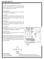
TRAVERSE DRIVE CONTROL BOARD (TDC)
The Traverse Drive Control Board has five potentiometers as
shown on drawing 6524511 which is included. These
potentiometers have been set at the factory to the positions
shown on the drawing. Also see FIG. 29.
Maximum Speed--The maximum speed potentiometer is preset to 2:30 position
for 90 Volts DC to the traverse motor.
Rev Torque--The Reverse Torque setting determines the maximum current
limit for driving the motor in the reverse direction. The
potentiometer is preset to the 3:00 position. It should not
require adjustment.
Fwd Torque--The Foward Torque setting determines the maximum current
limit for driving the motor in the forward direction. The
potentiometer is preset to the 3:00 position. It should not
require adjustment.
Accel - Decel--The potentiometer is factory preset to the minimum full
counterclockwise 8:30 position. This position turns the
Acceleration/Deceleration off for this application.
IR Compensation--The IR Comp control is preset to 9:30 position. Never adjust
past the 11:00 position.
Regulation of the traverse motor may be improved by slight adjustment of the IR COMP trim pot clockwise from its factory-set
position. Overcompensation causes the motor to oscillate or to
increase speed when fully loaded. If you reach such a point,
turn the IR COMP trim pot counterclockwise until the symptoms just disappear.
FIG. 29
Potentiometer
Clock Orientation
Terminal ends (Feet) are always at the 6:00 position,
no matter how the potentiometer is orientated on the board.
26
MACHINE SERVICE (Continued)
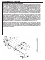
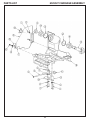
REPLACEMENT OF GRINDING HEAD SHAFT & BEARINGS
Remove grinding wheel and grinding wheel knob. The Grinding Head Spindle Assembly consists of the
grinding head spindle and a ball bearing press fit together. The left side ball bearing is slip fit on the opposite
end. To replace the spindle assembly remove the left side grinding wheel grip knob, square key and belt
cover. See FIG. 29. Loosen the 4 socket head cap screws on the motor plate to remove the poly-V belt.
Loosen the 2 set screws on the spindle pulley and remove the pulley, square key and pulley spacer. Push on
the right hand side of the spindle assembly to compress conical washers so there is no pressure on the
shaft retaining ring. Using a retaining ring pliers remove the small external retaining ring from the spindle
assembly. You can now remove the spindle assembly out the right side by lightly tapping on the left end with
a rubber mallet. The second ball bearing can be removed from the belt side of the Grinding Head Housing.
To reassemble place the 4 conical washers (2 Pair nested and then place the 2 pairs back to back) against
the ball bearing on the new spindle assembly. See FIG. 30. Thoroughly clean the housing bore and the
outside diameter of both bearings. Apply blue Loctite #242 to the outside diameter of the two bearings. Slide
the spindle assembly into the right side of the Grinding Head Housing. Install the bearing sleeve against the
bearing on the spindle assembly. Slip fit the new left side ball bearing onto the spindle assembly and into
grinding head housing. Install the 9/16-18 Locknut onto the spindle shaft and using a spanner wrench on the
right side of the spindle and a 7/8 deepwell socket on the left side, torque the locknut to 30 Ft. Lbs.
Replace the square key and the pulley pushing the pulley against the locknut with no end play. Apply blue
Loctite to the bore of the puley before instation. Next install blue Loctite #242 on the pulley setscrews and
tighten the two pulley set screws. Then remount the poly-V belt. (See Grinding Head Belt Tension Adjustment
in the adjusting section). Replace belt cover and square key and mount the left side grinding wheel grip knob
and tighten the two set screws.
FIG. 31
FIG. 30
27
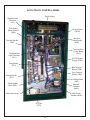
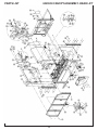
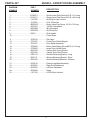
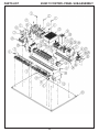
ACCU-TOUCH CONTROL PANEL
Touch Screen
Stepper Infeed
Controller
(SIC)
Door Safety
Switch Monitor
(SSM)
Vacuum Relay
(RE34)
Spin Drive
Control Board
(SDC)
Terminal Strip #2
(TB2)
Traverse Drive
Control Board
(TDC)
Programmable
Logic Controller
(PLC)
24 VDC Power
Supply (PWR)
Relay Board
(RT1)
Blue Terminal
Blocks (TBB)
Grey Terminal
Blocks (TBG)
Termial Strip #1
(TB1)
Low Voltage Relay
(LVR)
Grinding Motor
Relay (REL)
Magnetic
Contactor
(MAG)
Main Ground Lug
Main Circuit
Breaker (MCB)
AC Filter
(FTR)
28
ELECTRICAL TROUBLESHOOTING
SKILL AND TRAINING REQUIRED FOR ELECTRICAL SERVICING
This Electrical Troubleshooting section is designed for technicians who have the necessary electrical
knowledge and skills to reliably test and repair the ACCU-Touch electrical system. For those without that
background, service can be arranged through your local distributor.
This manual presumes that you are already familiar with the normal operation of the Grinder. If not, you
should read the Operators Manual, or do the servicing in conjunction with someone who is familiar with its
operation.
Persons without the necessary knowledge and skills should not remove the control box cover or attempt
any internal troubleshooting, adjustments, or parts replacement.
If you have any question not answered in this manual, please call your distributor. They will contact the
manufacturer if necessary.
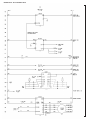
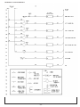
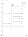
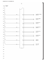
WIRE LABELS
All wires on the ACCU-Master have a wire label at each end for assembly and troubleshooting. The wire
label has a code which tells you wiring information. The first set of digits are the schematic wire number:
These identify the connection number. Look at the column numbers on the left side of the schematic rung
to identify the wire(s) The next number(s) are the Foley wire number. The next group of numbers or
letters are the code for the component to which the wire attaches. Example: RT1 for Relay Terminal 1.
The last set of numbers or letters are the number of the terminal on the component to which the wire
attaches.
ELECTRICAL TROUBLESHOOTING INDEX
AC Main Power Controls ..................................................................................................... Page 28
E-Stop ................................................................................................................................. Page 29
Machine Light ...................................................................................................................... Page 30
Spin Drive Controls in Spin Mode ........................................................................................ Page 31-32
Spin Drive Controls in Relief Mode ...................................................................................... Page 33-34
Grinding Motor Controls ....................................................................................................... Page 35
Dust Collector Controls ....................................................................................................... Page 36
Winch Controls ................................................................................................................... Page 37
Traverse Drive Controls--w/prox ......................................................................................... Page 38-39
Stepper Infeed Controls-- .................................................................................................... Page 40-41
System Error Messages ..................................................................................................... Page 42-42
Flashing Light ...................................................................................................................... Page 46
29
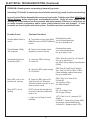
ELECTRICAL TROUBLESHOOTING (Continued)
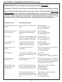
PROBLEM--AC Main Power Controls: no electrical power to control panel.
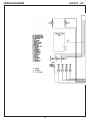
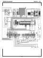
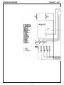
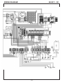
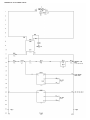
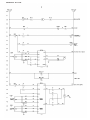
In your Product Packet Assembly, there are a series of prints. Find the print
titled ACCU-Touch Wiring Diagram, before starting the troubleshooting below.
Verify all wires shown on that drawing are correct and pull on wire terminals with
approximately 3 lbs force to verify there are no loose terminal connections and/or
no loose crimps between wire and terminal. If loose terminals are found, retighten
and retest system. If problem persists, test as listed below.
Possible Cause
Checkout Procedure
You must turn ON the
Switch on the top of
the control panel.
A. Look for Touch screen to
come on.
Machine works
Yes--end troubleshooting
No--go to Step B. next
Main Power Cord is not
plugged in
B. Plug in main power cord
Machine works
Yes--end troubleshooting
No--go to Step C. next
Main 20 amp outlet circuit
breaker has tripped in
building panel
C. Check circuit breaker and reset
if necessary. (Check wall outlet
with a light to make sure it works)
Machine works
Yes--end troubleshooting
No--but a light works in outlet--go to
Step D. next
No--but light does not work in outlet.
You must solve your power delivery
problem independent of machine.
Main 20 amp circuit breaker
has tripped in machine
panel
D. Check circuit breaker and reset
if necessary.
Machine works
Yes--end troubleshooting
No----go to Step E. next
No 115 Volts AC to Main
Circuit Breaker
E. Check for incoming power
(MCB) for 115 Volts AC
Check 115 Volts AC from (MCB) 01MBCbrown wire to Blue Terminal Block
TBB17 light blue wire.
Yes--go to Step F. next
No--Verify Filter function, check wiring.
No 115 Volts AC power from
2-Amp Circuit Breaker
F. Check for 115 Volts AC from
2-Amp Circuit Breaker
Check 115 Volts AC from 2-Amp CB
"157CB13-BL" to Blue Terminal Block
TBB17 light blue wire.
Yes--go to Step H. next
No--Check continuity of CB and replace.
No 115 Volts AC power from
Power Switch (PSW)
H. Check for 115 Volts AC from
Power Switch
Check 115 Volts AC from PSW terminal
#3 to Blue Terminal Block TBB17.
Yes--go to Step I. next
No--Check continuity of Switch and
replace
No 24 Volts DC power from
Power Supply
I. Check for 24 Volts DC from
Power Supply (PWR)
Check 24 Volts DC from PWR V+ to VYes--Verify wiring to Touch Screen
No--Verify power to PWR. Replace
power supply.
30
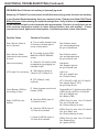
ELECTRICAL TROUBLESHOOTING (Continued)
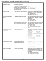
PROBLEM--Red E-Stop screen displayed on Touch Screen
In your Product Packet Assembly, there are a series of prints. Find the print
titled ACCU-Touch Wiring Diagram, before starting the troubleshooting below.
Verify all wires shown on that drawing are correct and pull on wire terminals with
approximately 3 lbs force to verify there are no loose terminal connections and/or
no loose crimps between wire and terminal. If loose terminals are found, retighten
and retest system. If problem persists, test as listed below.
Possible Cause
Checkout Procedure
You must push the green
Push to Start Switch (PSS)
A. Listen for magnetic contactor
(MAG) to pull in with a clunk.
Machine works
Yes--end troubleshooting
No--go to Step B. next
Pull red e-stop button out
B. Repeat push the green button
(SSS) again.
Machine works
Yes--end troubleshooting
No--go to Step C. next
115V power not delivered to
MAG coil
C. Check at Magnetic contactor coil (MAG) Term #A1 to A2 for 115 Volts AC
for 115 Volts AC with main electrical Yes--replace magnetic starter if not
pulling in with click.
power on and pushing (SSS)
No--go to Step D. next
Controller E-stop ouput
relay on
D. Check on relay board (RT1) for
light on for output "F" (farthest light
to right)
Light is:
Off-- Controller software corrupt or
missing, or Relay Board not working.
On-- go to step E. next
Controller E-stop relay no
continuity
E. With the machine power on,
Relay light on, measure across
relay contacts.
(RT1) terminals F+ to F- for 115 Volts AC
Yes-- Replace output relay F in (RT1)
No-- go to step F. next
(SSS) Is bad
F. With the machine power on,
measure across normally open
contacts of (SSS)
(SSS) Term #3 to #4 for 115 Volts AC
(SSS) not pushed, "0" Volts AC (SSS)
pushed.
No-- Replace (PSS)
Yes-- go to step G. next
(ESS) Is bad
G. With the machine power on,
measure across normally closed
contacts of (ESS)
(ESS) Term #1 to #2 for "0" Volts
(ESS) pulled out, 115 Volts AC (ESS)
pressed in.
No-- Replace (ESS)
Yes-- go to step H. next
Bad wires
H. With the machine power off,
verify continuity of wires and
connections.
Measure continuity of wires #11, 12, 15, 22,
35, 37, 50, 59, 60, 146, 147, 148, 149, &
150. Replace any bad wires or repair
loose connections.
31
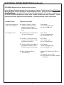
ELECTRICAL TROUBLESHOOTING (Continued)
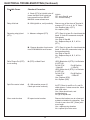
PROBLEM--Machine light is not working
In your Product Packet Assembly, there are a series of prints. Find the print
titled ACCU-Touch Wiring Diagram, before starting the troubleshooting below.
Verify all wires shown on that drawing are correct and pull on wire terminals with
approximately 3 lbs force to verify there are no loose terminal connections and/or
no loose crimps between wire and terminal. If loose terminals are found, retighten
and retest system. If problem persists, test as listed below.
Possible Cause
Checkout Procedure
Light switches are
not turned on or there
is a bad bulb
Light works
A. Turn on machine light toggle
switch on light. Check the light bulb Yes--end troubleshooting
in another light fixture or replace with No--go to Step B. next
a new bulb. Plug a different light that
is known to work into light plug.
Wire cord is bad
B. Check for 115 Volts AC at
Terminal Strip
Check for 115 Volts AC across terminals # 6 & 7 on Terminal Strip 2 (TB2)
Yes--replace cord for light
No--go to Step C. next
Wiring is bad
C. Check continuity of wiring from
MAG to Terminal Block
Check wiring and tighten or replace
any damaged or loose parts.
*NOTE: The light may flicker
on and off when the grinding
motor is turned on. This is due
to the high current draw on the
system when starting the grind
motor.
32
ELECTRICAL TROUBLESHOOTING (Continued)
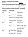
PROBLEM--Spin Drive not working in (manual) jog mode and in SPIN MODE.
Assuming 115 Volts AC to control panel and all other manual (jog) mode functions are working.
In your Product Packet Assembly, there are a series of prints. Find the print titled ACCU-Touch
Wiring Diagram before starting the troubleshooting below. Verify all wires shown on that
drawing are correct and pull on wire terminals with approximately 3 lbs force to verify there are
no loose terminal connections and/or loose crimps between wire and terminal. If loose
terminals are found, tighten and retest system. If problem persists, test as listed below.
Possible Cause
Checkout Procedure
Spin Speed Pot (SSP) set
to zero
A. Set (SSP) to 200 on the control
panel.
Spin Motor works
Yes--end troubleshooting
No--go to Step B. next
Spin Motor Switch not on
on Touch Screen
B. Turn spin drive switch on (touch
green area) from SPIN MANUAL
screen.
Spin Motor works
Yes--end troubleshooting
No--go to Step C. next
Door is open
C. Alarm on screen should indicate
that the door must be closed for the
spin drive to operate. Close door.
Spin Motor works
Yes--end troubleshooting
No--go to step D. next
Circuit breaker 42 is
tripped (4A)
D. Reset circuit breaker switch
(Tripped by current overload)
check that reel is free spinning
Spin Motor works
Yes--end troubleshooting
No--go to step E. next
Relay 9 (RT1) is not
working
E. Check for (SDC) input of
115 Volts AC
(SDC) Term #L1 to #L2 for 115 Volts AC
Yes--skip to step H. next
No--go to Step F. next
Verify Light is on
F. Check (RT1) for light #9 to be on Light is ON.
(Door must be closed and spin drive Yes--go to Step G. next
switch on)
No--Bad PLC, RT1, cables, or Software.
Verify Continutiy of
relay 9 in RT1
G. With light #9 on, Check (RT1)
relay 9 for continuity.
(RT1) Term 9+ to term 9- for 115 Volts AC
No-Check CB42 (4-Amp) for 115 Volts AC
-check from CB to Blue Terminal Block 17
Yes--Replace relay #9 in (RT1)
Relay 4 (RT1) is not
working (Spin/Torque
selector relay)
H. With 115 Volts AC at Term L1
and L2, check (SDC) output. Have
Spin speed pot (SSP) set at 400
(SDC) term A1 to term A2 measure
approx 90 Volts DC
Yes--Skip to Step L.
No-- go to step I. Next
I. With 115 Volts AC at Term L1
and L2, check (SDC) output. Have
Relief Torque Pot (RTP) set to Red
Line.
(SDC) term A1 to term A2 measure
approx 12 Volts DC
No-- Skip to step N.
Yes-- go to step J. Next
33
ELECTRICAL TROUBLESHOOTING (Continued)
Possible Cause
Checkout Procedure
J. Check (RT1) for light #4 to be on Light is:
Insure that Spin Drive switch has
On-- go to Step K. next
been pressed on from SPIN MANUAL Off-- Contact factory
screen at least once
Relay #4 is bad
K. With light #4 on, verify continuity
Remove one of the wires at Terminal 4,
measure (RT1) 4+ to 4- for "0" Ohms
Yes--Replace (SDC)
No--replace Relay 4 (RT1)
Reversing relay(s) bad
(RT1)
L. Measure voltage at spin motor
(RT1) Term A+ to term D+ should read the
same 90 Volts DC measured at step H.
Note polarity
Yes--Skip to Step O.
No-- go to Step M. next
M. Reverse direction of spin motor
from SPIN MANUAL touch screen
(RT1) Term A+ to term D+ should read the
same 90 Volts DC measured at step H.,
but opposite polarity
Yes--Skip to Step O.
No-- Replace relays A, B, C, & D in
(RT1)
Spin Speed Pot (SSP)
is not working
N. (SSP) on Main Panel
(SDC) Black wire of (SSP)- H to Red wire
of (SSP)-W
Pot full CCW
Pot Full CW
4.4 Volts DC
0 Volts DC
(SDC) White wire of (SSP)- L to Red wire
of (SSP)-W
Pot full CCW
Pot Full CW
0 Volts DC
4.4 Volts DC
Yes-- Replace (SDC)
No-- Replace (SSP)
Spin Drive motor is bad
O. With machine power off,
Check spin motor continuity
At (RT1) Term A+ and B+ or C+ and D+
check approx. 0 ohms across the black
and white wires
Yes-- Motor should work, end troubleshooting.
No--go to Step P. next
Worn motor brushes
P. Inspect motor brushes
Remove the brushes one at a time and
maintain orientation for reinsertion. See
if brush is worn short 3/8" [10mm] minimum length.
Yes-- replace motor brushes
No-- replace Spin Drive motor
34
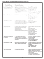
ELECTRICAL TROUBLESHOOTING (Continued)
PROBLEM--Spin Drive not working in (manual) jog mode and in RELIEF MODE.
Assuming 115 Volts AC to control panel and all other manual (jog) mode functions are working.
In your Product Packet Assembly, there are a series of prints. Find the print titled ACCU-Touch
Wiring Diagram, before starting the troubleshooting below. Verify all wires shown on that
drawing are correct and pull on wire terminals with approximately 3 lbs force to verify there are
no loose terminal connections and/or loose crimps between wire and terminal. If loose
terminals are found, tighten and retest system. If problem persists, test as listed below.
Possible Cause
Checkout Procedure
Relief Torque Pot (RTP) set A. Set (SSP) to 20 on the control
panel.
to zero
Spin Motor works
Yes--end troubleshooting
No--go to Step B. next
Spin Motor Switch not on
on Touch Screen
B. Turn spin drive switch on (touch
green area) from RELIEF MANUAL
screen.
Spin Motor works
Yes--end troubleshooting
No--go to Step C. next
Door is open
C. Alarm on screen should indicate
that the door must be closed for the
spin drive to operate. Close door.
Spin Motor works
Yes--end troubleshooting
No--go to step D. next
Circuit breaker 42 is
tripped (4A)
D. Reset circuit breaker switch
(Tripped by current overload)
check that reel is free spinning
Spin Motor works
Yes--end troubleshooting
No--go to step E. next
Relay 9 (RT1) is not
working
E. Check for (SDC) input of
115 Volts AC
(SDC) Term #L1 to #L2 for 115 Volts AC
Yes--skip to step H. next
No--go to Step F. next
Verify Light is on
F. Check (RT1) for light #9 to be on Light is
(Door must be closed and spin drive On--go to Step G. next
switch on)
No--Bad PLC, RT1, cables, or Software.
Verify Continutiy of
relay 9 in RT1
G. With light #9 on, Check (RT1)
relay 9 for continuity.
(RT1) Term 9+ to term 9- for 115 Volts AC
No--Check CB42 (4-Amp) for 115 VAC
-check from CB to Blue Term Block 17
Yes--Replace relay #9 in (RT1)
Relay 4 (RT1) is not
working
H. With 115 Volts AC at Term L1
and L2, check (SDC) output. Have
Relief Torque Pot (RTP) set at Red
Line.
(SDC) term A1 to term A2 measure
approx 12 Volts DC
Yes--Skip to Step L.
No-- go to step I. Next
I. With 115 Volts AC at Term L1
and L2, check (SDC) output. Have
Spin Speed Pot (SSP) set to 400
(SDC) term A1 to term A2 measure
approx 90 Volts DC
No-- Skip to step N.
Yes-- go to step J. Next
35
ELECTRICAL TROUBLESHOOTING (Continued)
Possible Cause
Checkout Procedure
J. Check (RT1) for light #4 to be off
Insure that Spin Drive switch has
been pressed on from RELIEF
MANUAL screen at least once
Light is:
Off-- go to Step K. next
On-- Contact factory
Relay #4 is bad
K. With light #4 on, verify continuity
Remove one of the wires at Terminal 4,
measure (RT1) 4+ to 4- for "0" Ohms
Yes--Replace relay 4 (RT1)
No--replace (SDS)
Reversing relay(s) bad
(RT1)
L. Measure voltage at (RT1)
(RT1) Term A+ to term D+ should read the
same 12 Volts DC measured at step H.
Note polarity
Yes--Skip to Step M.
No-- Replace relays A, B, C, & D in
(RT1)
M. Reverse direction of spin motor
from SPIN MANUAL touch screen
(RT1) Term A+ to term D+ should read the
same 12 Volts DC measured at step H.,
but opposite polarity
Yes--Skip to Step O.
No-- Replace relays A, B, C, & D in
(RT1)
Relief Torque Pot (RTP)
is not working
N. (RTP) on Main Panel
(SDC) Black wire of (RTP)- H to Red wire
of (RTP)-W
Pot full CCW
Pot @ Red line
.2 Volts DC
.1 Volts DC
(SDC) White wire of (RTP)- L to Red wire
of (RTP)-W
Pot full CCW
Pot @ Red line
.1 Volts DC
.2 Volts DC
Yes-- Replace (SDC)
No-- Replace (SSP)
Spin Drive motor is bad
O. With machine power off,
Check spin motor continuity
At (RT1) Term A+ and B+ or C+ and D+
check approx. 0 ohms across the black
and white wires
Yes-- Motor should work, end
troubleshooting.
No--go to Step P. next
Worn motor brushes
P. Inspect motor brushes
Remove the brushes one at a time and
maintain orientation for reinsertion. See
if brush is worn short 3/8" [10mm] minimum length.
Yes-- replace motor brushes
No-- replace Spin Drive motor
36
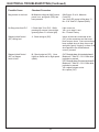
ELECTRICAL TROUBLESHOOTING (Continued)
PROBLEM--Grinding motor not working in (manual) jog mode.
Assuming 115 Volts AC to control panel and all other manual (jog) mode functions are working.
In your Product Packet Assembly there are a series of prints. Find the print titled ACCU-Touch
Wiring Diagram, before starting the troubleshooting below. Verify all wires shown in the
drawing are correct and pull on wire terminals with approximately 3 lbs force to verify there are
no loose terminal connections and/or loose crimps between wire and terminal. If loose
terminals are found, tighten and retest system. If problem persists, test as listed below.
Possible Cause
Checkout Procedure
Grinding Motor Switch is
not on
A. Turn switch on from either SPIN Grinding Motor works
MANUAL screen or RELIEF MANUAL Yes--end troubleshooting
No--go to Step B. next
screen
Circuit Breaker (CB28)
15A is tripped
B. Reset circuit breaker switch
(tripped by current overload)
Grinding Motor works
Yes--end troubleshooting
No--go to step C. next
Grinding Motor Relay is
not working (REL)
C. Check for (REL) incoming
115 Volts AC
(REL) Term #L1 to #L2 for 115 Volts AC
Yes--go to step D. next
No--Verify wiring, replace Circuit Breaker
(CB28)
D. Check for (REL) output voltage
of 115 Volts AC
(REL) Term #T1 to #T2 for 115 Volts AC
Yes-- Verify 115 VAC at TB1-1 & TB1-2,
Check terminals, replace Grind motor.
No--go to step E. next
Relay (REL) coil or contacts are not working
E. Check for (REL) input of 24
Volts DC at the coil. Reminder,
Grind Drive switch must be on and
doors must be closed.
(REL) Term A1 to Term A2 for
24 Volts DC
Yes--Replace (REL)
No--Skip to Step F.
Relay 5 (RT1) is not
working
F. (RT1) check that the light is on
for relay 5, make sure grind drive
swich is on
Light is:
On-- Go to Step I. next
Off--Contact Factory
I. Light is on for Relay 5, check
continuity
(RT1) Term 5+ to 5-, measure DC
voltage
0 Volts DC-- Check wiring, Relay (REL)
should work, end troubleshooting.
24 Volts DC-- Replace relay 5 (RT1)
37
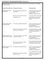
ELECTRICAL TROUBLESHOOTING (Continued)
PROBLEM--Dust Collector not working in (manual) jog mode.
Assuming 115 Volts AC to control panel and all other manual (jog) mode functions are working.
In your Product Packet Assembly, there are a series of prints. Find the print titled ACCU-Touch
Wiring Diagram, before starting the troubleshooting below. Verify all wires shown on that drawing are correct and pull on wire terminals with approximately 3 lbs force to verify there are no
loose terminal connections and/or no loose crimps between wire and terminal. If loose
terminals are found, tighten and retest system. If problems persists, test as listed below.
Possible Cause
Checkout Procedure
Dust Collector Switch is
not on (Vacuum)
A. Turn on switch located on top
of Vacuum in the back right of
corner of the machine.
Dust Collector works-Yes--end troubleshooting
No--go to Step B. next
Dust Collector Switch
(Vacuum) on touch screen
is not on
B. Turn switch on from SPIN
MANUAL or RELIEF MANUAL
screen.
Dust Collector works-Yes--end troubleshooting
No--go to Step C. next
Vacuum not working
C. Check for 115 Volts AC at the
receptacle plug by plugging in a
hand drill or light.
Light works
Yes--Replace Vacuum
No--go to Step D. next
(RT1) relay E is not working
D. With Vacuum switch on,
Check for (RT1) Relay E on
Light is on:
Yes--go to step E. next
No--Contact Factory
E. (RT1) Relay E, verify
continuity
(RT1) Term #E+ to #E- for 115 Volts AC
Yes--replace Relay E (RT1)
No--go to Step F. next
Circuit Breaker (CB32) is
not working (3-amp)
F. Check for power out of circuit
breaker (CB32)
Terminal Block 17 (light blue wire) #02 to
(CB32) (brown) #156 for 115 Volts AC
Yes--go to Step G. next
No--replace (CB2)
Relay 34 (RE34) is not
working
G. Check for (RE34) input of
115 Volts AC at coil.
(RE34) Term 0 to term 1 for 115 Volts AC
Yes-- go to Step H. next
No--Check continuity of wires.
H. Check for (RE34) input of
115 Volts AC at contacts
(RE34) Term 8 to term 4 for 115 Volts AC
Yes--go to Step I. next
No--Check continuity of wires.
I. Check for (RE34) output of
115 Volts AC at contacts
(RE34) Term 6 to term 2 for 115 Volts AC
Yes--Replace Plug
No--replace (RE34)
38
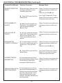
ELECTRICAL TROUBLESHOOTING (Continued)
PROBLEM--Winch does not work in either direction.
In your Product Packet Assembly, there are a series of prints. Find the print titled ACCU-Touch
Wiring Diagram, before starting the troubleshooting below. Verify all wires shown on that
drawing are correct and pull on wire terminals with approximately 3 lbs force to verify there are
no loose terminal connections and/or loose crimps between wire and Terminal. If loose
terminals are found, tighten and retest system. If problem persists, test as listed below.
Possible Cause
Checkout Procedure
7 amp circuit breaker on
winch motor is tripped
A. Reason: Check for a lifting
overload condition or wiring
shorted to ground. Reset
breaker located at end of winch
motor.
Winch works-Yes--end troubleshooting
No--go to Step B. next
No voltage to motor
B. Check that motor coil cord from
DC motor is plugged in
Winch works-Yes--end troubleshooting
No--go to Step C. next
C. Check for 115 Volts AC at the
plug end winch cord wire #6 by
plugging in a hand drill
Drill works-Yes--replace winch
No-- go to Step D. next
D. Check for Machine is plugged in
Start button is pressed. (Red
E-Stop Screen must not be up)
Winch works-Yes--end troubleshooting
No--go to Step E. next
E. Verify wiring from MAG to
Terminal Strip 2.
Measure 115 Volts AC from TB2-6 to
TB2-7.
Yes--replace cord to winch
No--Verify power out of mag. Replace
bad wiring.
39
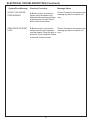
ELECTRICAL TROUBLESHOOTING (Continued)
PROBLEM--Traverse Drive not working in (manual) jog mode
Assuming 115 Volts AC to control panel and all other manual (jog) mode functions are working.
In your Product Packet Assembly, there are a series of prints. Find the print titled ACCU-Touch
Wiring Diagram, before starting the troubleshooting below. Verify all wires shown on that
drawing are correct and pull on wire terminals with approximately 3 lbs force to verify there are
no loose terminal connections and/or loose crimps between wire and terminal. If loose
terminals are found, tighten and retest system. If problem persists, test as listed below.
Possible Cause
Checkout Procedure
Traverse Speed Pot (TSP)
set to zero
A. Set (TSP) to 35 on the control
panel
Traverse works
Yes--end troubleshooting
No--go to step B. next
Traverse Belt Clamp
release lever released
B. Insure release lever is in adjusted
properly. See Adjustments section
of this manual.
Traverse works
Yes--end troublshooting
No--go to Step C. next
Circuit Breaker 32 (CB32)
(3 amp) tripped
C. Too heavy a grind causes
grinding head traverse motor to
overload and trip the circuit breaker.
Reset (CB32)
Traverse works
Yes--end troublshooting
No--go to Step D. next
Traverse Drive Control
(TDC) do not have power
D. Check for 115 Volts AC
incoming to (TDC) (insure
traverse right or left has been
pressed at least once)
On (TDC) Term L1 to
L2 for 115 Volts AC
Yes--Skip to Step H.
No--go to Step E. next
Relay 8 (RT1) is bad
E. Check for relay 8 (RT1)
light on (insure traverse right
or left has been pressed at least
once)
Light is:
On-- go to Step F. next
Off-- Contact Factory
F. Check relay 8 for continuity,
Insure relay 8 light is on
(RT1) Term 8+ to 8- read
115 Volts AC
Yes-- Replace Relay 8 (RT1)
No-- go to Step G. next
G. Check CB32 for voltage
(CB32) from Line neutral, Light Blue
wire at the line filter wire # 02FTRBU,
to wire #156CB32-BL at CB32
measure 115 Volts AC:
No-- Replace CB32
Yes-- Verify continutiy of wires to RT1.
Replace or repair bad wire(s)
Circuit Breaker 32 (CB32)
bad
40
ELECTRICAL TROUBLESHOOTING (Continued)
Possible Cause
Checkout Procedure
H. Check for 90 Volts DC across
(TDC) terminals A! to A2 this voltage
drives the DC traverse motor.
NOTE: Traverse must be on and
have (TSP) turned full CW to maximum
voltage of 90 VDC
Check (TDC) terminals
A1 to A2 for 90 Volts DC
Yes--go to step I. next
No--go to Step J. next
Traverse Motor is bad
I. Check traverse motor continuity
Remove wires from terminals
A1 & A2 0 ohms across
the black and white wires
Yes--go to Step J. next
No--go to Step N.
Check Relays 2 and 3
J. (RT1) Verify that relay 2 light
comes on when Traverse Right is
pressed, and that relay 3 light comes
on when Traverse Left is pressed
Lights come:
On-- go to step K. next
Off-- Skip to step L.
(TSP) (10K) is bad
K. Check (TSP) for 10,000 ohms
Remove three wires from (TDC)
red from term S2
white from term S0
black from inline connector (Wire 39)
Check for 10,000 ohms red to white
wires
Full CCW--0 ohms
Full CW--10,000 ohms
Red to black wires
Full CCW--10,000 ohms
Full CW--0 ohms
Yes--go to Step L. next
No--replace (TSP)
Gap between flag and prox
is incorrect.
L. Gap between flag and Prox
should be 3/16" to 1/4" [4-6mm].
Prox light does not light when flag is
under prox.
If incorrect, adjust per adjustment
section of manual.
Traverse works-Yes-- End troubleshooting
No-- go to step M. next
Proximity switch is bad
M. From the Touch screen, Enter
"HELP" screen from main menu.
Follow instructions on screen to verify
traverse proximity switches are ok.
Switch is
Good-- Replace (TDC)
Bad-- Replace switch
Worn motor brushes
N. Inspect Motor Brushes
Remove the brushes one at a time and
maintain orientation for reinsertion.
See if brush is worn short, 3/8" [10 mm]
minimum length.
Yes--replace motor brushes
No--replace Traverse Drive Motor
No DC Voltage from (TDC)
Traverse Drive Control
41
Note:If voltage is less than 90 VDC
verify pots on TDC. See page 24
ELECTRICAL TROUBLESHOOTING (Continued)
PROBLEM--Stepper Infeed not working in (manual) jog mode.
Assuming 115 Volts AC to control panel and all other manual (jog) mode functions are working.
In your Product Packet Assembly, there are a series of prints. Find the print titled ACCU-Touch
Wiring Diagram, before starting the troubleshooting below. Verify all wires shown on that drawing
are correct and pull on wire terminals with approximately 3 lbs force all terminals to verify there
are no loose terminal connections and/or loose crimps between wire and terminal. If loose
terminals are found, tighten and retest system. If problem persists, test as listed below.
Possible Cause
Checkout Procedure
Infeed Jog Switch is not
held to on position
A. Hold switch on in
either direction
Stepper motor works
Yes--end troubleshooting
No--go to Step B. next
Actuator is at physical limit
B. Move stepper in opposite direction
Stepper Motor works
Yes--end troubleshooting
No--go to step C. next
Circuit Breaker (CB13)
is tripped (2 amp)
C. Reset circuit breaker switch
(tripped by current overload)
Grinding head stepper infeed
mechanism jammed causing overload
Stepper Motor works
Yes--end troubleshooting
No--go to step D. next
High Low Switch is not on
high speed
D. Put switch on high speed
(rabbit) for ease of checkout of
Stepper Infeed Control (SIC)
High speed works
Yes--end troubleshooting
No--go to Step E. next
Stepper motor drive
coupling is loose
E. You can feel stepper pulses on
motor when (HLS) is on high or low
& (IJS) switch is depressed in either
up or down direction. Open stepper
infeed inspection plate to check for
loose coupling. Retighten coupling
to drive actuator screw. See
adjustment section of manual.
Stepper works-Yes--end troubleshooting
No--go to Step F. next
No DC voltage to Stepper
Infeed Control (SIC)
F. (SIC) Check for 24 Volts DC
Power in
(SIC) Term GND to V+ measure
24 Volts DC
Yes-- go to step G. next
No-- Skip to step H.
No DC Voltage to OPTO
terminal of (SIC)
G. (SIC) Check voltage at OPTO
terminal
(SIC) Term GND to OPTO measure 24 Volts DC
Yes-- go to step I.
No-- Replace wire #60 (with
resistor)
42
ELECTRICAL TROUBLESHOOTING (Continued)
Possible Cause
Checkout Procedure
Mag contact or wire bad
H. Measure voltage at (MAG) insure
power is on, and green (PSS) has
been pressed.
(MAG) term 13 to 14, Measure
0 volts DC
Yes--Verify DC power to Mag term 13
No-- if 24 Volts DC, Replace (MAG)
No Step pulse from PLC
I. Check light Y0 on PLC. While
pressing up or down it should light
(pressing down Y1 will also light)
Light comes on:
Yes-- go to step H. next
No-- Contact Factory
Stepper Infeed Control
(SIC) Wiring bad
J. Check wiring at (SIC).
Insure all wires are connected at the
(SIC) to the connectors and that none
have become loose. Some connections
have multiple wires in them, be sure all
are tight by gently "tugging" on them. If all
wires appear to be connected and
correct, proceed:
Stepper Infeed Control
(SIC) or Stepper
motor is bad
K. Check output at (SIC). Have
High/Low Switch set on high speed
(rabbit)
(SIC) Terminal phase A to terminal phase A'
Measure 4.7 Volts DC, 0.2-0.3 Volts while
jog button is pressed.
(SIC) Terminal phase B to terminal phase B'
Measure 4.7 Volts DC, 0.2-0.3 Volts while
jog button is pressed.
Yes--replace stepper motor
No--replace (SIC)
43
ELECTRICAL TROUBLESHOOTING (Continued)
PROBLEM--No Manual (jog) cycle or Auto Cycle stops because of a system error message
on Touch Screen.
System Error Message
STORE FINGER FOR
SPIN GRIND
ROTATE HEAD DOWN
FOR SPIN GRIND
HOME TRAVERSE (TO
RIGHT PROX) TO START
Checkout Procedure
Message Status
A. Rotate index finger assembly to
spin position
Clears--Proceed to next system
error message you have or
continue running.
Remains--go to Step B. next
B. Check (PLC) input from Finger
Stored/Down prox
From "Help" Screen verify Finger
Stored/Down prox input is on
(Red) Follow instructions on
screen.
A. Rotate grind head assmbly down
Clears--Proceed to next system
error message you have or
Continue running.
Remains--go to Step B. next
B. Check (PLC) input from Head in
Relief Pos. (Position) prox
From "Help" Screen verify Head
in Relief Pos. prox input is working. Follow instructions on
screen.
A. Jog Grind head to right prox with
touch screen controls
Clears--Proceed to next system
error message you have or
Continue running.
Remains--go to Step B. next
B. Check (PLC) input from Right
Traverse prox switch
ROTATE HEAD UP FOR
RELIEF GRIND
A. Rotate grind head assmbly up
B. Check (PLC) input from Head in
Relief Pos. prox
44
From "Help" Screen verify Right
Traverse Prox input is working.
Follow instructions on screen.
Clears--Proceed to next system
error message you have or
Continue running.
Remains--go to Step B. next
From "Help" Screen verify Head
in Relief Pos. prox input is working. Follow instructions on
screen.
ELECTRICAL TROUBLESHOOTING (Continued)
System Error Message
Checkout Procedure
Message Status
A. Release finger. Make sure that
the finger is allowed to come
foreward at least once.
Clears--Proceed to next system error
message you have or continue running.
Remains--go to Step B. next
B. Check (PLC) input from Door
Saftey Switch
From "Help" Screen verify Finger
Stored / Down prox input is working.
Follow instructions on screen.
ENTER NUMBER OF
BLADES
A. Blade count is required to run
Relief grind. Count blades and
enter the number under the
Blade # Field.
Clears--Proceed to next system error
message you have or continue running.
LOW VOLTAGE DETECTED
A. Input line voltage has dropped
below 100V. Plug machine into a
better source of power. See
Power requirements at front of
manual.
Clears--Proceed to next system error
message you have or continue running.
DOOR MUST BE
CLOSED TO OPERATE
A. For safety reasons, door must
be closed to operate spin and / or
grind motors. Close and latch
door.
Clears--Proceed to next system error
message you have or continue running.
Remains--go to Step B. next
B. Check (PLC) input from Door
Saftey Switch
From "Help" Screen verify Head in
Relief Pos. prox input is working.
Follow instructions on screen.
RELEASE FINGER FOR
RELIEF
INCREASE TORQUE
KNOB SETTING
A. An excessive amount of time
Clears--Proceed to next system error
has passed between blade indexes message you have or continue runor at the start of a relief cycle.
ning.
Increase the Relief Torque Pot.
TORQUE KNOB LOW OR A. An excessive amount of time
has passed at the beginning of a
DIRECTION WRONG
Relief grind cycle before the finger
down prox was detected. Verify
Torque pot setting and / or spin
direction. Reminder: Blade should
push finger down.
45
Clears--Proceed to next system error
message you have or continue running.
ELECTRICAL TROUBLESHOOTING (Continued)
PROBLEM--No Manual (jog) cycle or Auto Cycle stops because of a system error message
on Touch Screen (Continued)
System Error Message
FINGER NOT
RELEASED, CHECK
LH PROX POS
(POSITION)
Checkout Procedure
Message Status
A. During a relief grind cycle, the
PLC did not see the finger released
at the left prox position. Verify that the
setting of the left traverse prox allows
the finger to come off the blade.
Clears--Proceed to next system
error message you have or
continue running.
Remains--go to Step B. next
B. Check (PLC) input from Finger
Stored/Down prox
From "Help" Screen verify Finger
Stored/Down prox input is Working. Follow instructions on
screen.
MOVE NOT POSSIBLE IN A. Press "Resume" on touch screen
to finish current cycle.
PAUSE MODE
Clears--Proceed to next system
error message you have or
Continue running.
MACHINE IS IN PAUSE
MODE, PRESS RESUME
A. Machine was left in pause mode
after last cycle. Press "resume" on
touch screen.
Clears--Proceed to next system
error message you have or
Continue running.
DOOR OPENED WHILE
GRIND AND / OR SPIN
ON
A. Door was opened while potentially
dangerous operations were still on.
Turn off motors, pause, or finish cycle
before opening doors.
Clears--Proceed to next system
error message you have or
Continue running.
INCREASE TRAVERSE
KNOB SETTING
A. An excessive amount of time has
passed at the beginning of an auto
cycle before the grind head assy. has
moved. Increase Traverse Speed pot
or check that carriage is not released.
Clears--Proceed to next system
error message you have or
Continue running.
TRAVERSE TIMEOUT,
CHECK POT OR SETUP
A. An excessive amount of time has
passed during a traverse cycle.
Increase Traverse Speed pot or verify
that carriage assembly is not released or hitting an obstruction.
Clears--Proceed to next system
error message you have or
Continue running.
46
ELECTRICAL TROUBLESHOOTING (Continued)
System Error Message
Checkout Procedure
Message Status
ACCEPT VALUES BEFORE RUNNING
A. Before an auto cycle can be
started, verify the values in the
displayed boxes and accept them
by pressing the "Accept Values"
button on the touch screen.
Clears--Proceed to next system error
message you have or continue running.
OPEN DOOR TO RESET
LIGHT
Clears--Proceed to next system error
A. Before an auto cycle can be
message you have or continue runstarted, the last cycle completed
must be cleared. Open the door or ning.
press the "Cycle Complete" button
on the main screen to reset.
47
ELECTRICAL TROUBLESHOOTING (Continued)
PROBLEM--Flasher light does not turn on at end of automatic cycle.
In your Product Packet Assembly, there are a series of prints. Find the print titled ACCU-Touch
Wiring Diagram, before starting the troubleshooting below. Verify all wires shown on that
drawing are correct and pull on wire terminals with approximately 3 lbs force to verify there are
no loose terminals. If loose terminals are found, tighten and retest system. If problem persists,
test as listed below.
Possible Cause
Checkout Procedure
Bulb is burned out
A. Remove bulb and test continuity
Bulb- Measure approx 300 Ohms
Yes--go to Step B. next
No--Replace bulb
Flasher (FLR) is bad
B. (FLR) Unplug flasher at terminal
(RT1) 7+ and touch lead to black
wire at (RT1) 7-
Light works:
Yes--go to step C. next
No-- Replace Flasher Assy.
No 115 Volts AC to flasher
C. After a cycle has completed,
measure voltage to Flasher.
(RT1) Term. 7+ to Blue Term Block 17
Measure 115 Volts AC
Yes-- Verify continuity in cord,
Replace flasher
No-- go to step D. next
Relay 7 (RT1) is bad
D. After a cycle has completed,
check (RT1) for light 7 to be on
Light is on:
Yes-- go to step E. next
No-- Contact Factory
E. Check continuity of relay 7
(RT1) Term 7+ to 7- Measure 115 Volts
AC
Yes-- Replace Relay 7 (RT1)
No-- go to step F. next
F. Reset CB32
Press in on Circuit breaker CB32 on
front of control panel. Works
Yes--End Troubleshooting
No-- Replace CB32
Circuit Breaker (CB32)
tripped
48
THIS PAGE LEFT INTENTIONALLY BLANK FOR NOTE TAKING PURPOSES.
49
MECHANICAL TROUBLESHOOTING
Possible Cause
Checkout Procedure
PROBLEM--Reels ground have high/low blades.
Traverse Speed set to fast.
Check roundness using a magnetic base dial indicator.
Traverse speed should be set approximately 12 ft/min
[4 meters/min] if roundness is varying.
Lineal bearings for the grinding head
carriage are out of adjustment (loose)
or have grit buildup causing uneven
traversing load.
Relubricate and adjust linear bearings per adjustment
section. If problem persists, replace lineal bearings on
the carriage base. Check for any holes in the bellows
that would permit any grinding grit penitration. See
adjustment section for lineal bearing replacement.
PROBLEM--Excessive grinding stock being removed
when traversing to the right in the relief grinding mode.
Gib adjustment for the relief finger assembly
is loose so reel finger has movement.
When traversing to the right minimum
grinding stock removal should be seen as
compared with heavy stock removal when
traversing to the left.
Tighten the set screws for the gib adjustment. See
procedure in the adjustment section in the manual.
PROBLEM--Grinding stock removal from reel is irregular during spin grinding.
Lineal bearings on the grinding head
carriage are too loose.
The lineal bearing must be preloaded to the traverse
shafts with no vertical movement. See manual adjustment
section for carriage linear bearing adjustments.
PROBLEM--Carriage traversing varies speed while grinding.
Lineal bearings in the carriage do not rotate
freely.
Check for grinding grit getting into the lineal bearings and
cause excessive driving torque of carriage. Abrasive
noise is detectable when excessive grit is in the lineal
bearings. Replace the four lineal bearings in the main
carriage. Check bellows for holes and replace if necessary.
Traverse Belt is slipping.
Check the spacing of the clamp to the support block.
Clamp tip may need to be adjusted if the belt is slipping.
The belt may also be too loose. See Adjustments section
for proper measurements of clamp gap and belt tension.
50
MECHANICAL TROUBLESHOOTING (Continued)
PROBLEM--Too heavy a burr on cutting edge of reel blades.
Possible Cause
Checkout Procedure
Traverse speed set to high causing a heavy
burr on the reel blade when spin grinding.
Traverse speed should be set lower approximately 12 ft/min.
[4 meters/min.] for a smaller burr on cutting edge.
PROBLEM--Cone shaped reel after grinding.
Grinding head travel not parallel to the reel
center shaft.
Grinding head travel was not setup parallel to the reel
center shaft in vertical and horizontal planes. See Align
the Reel Section in Operator's Manual.
PROBLEM--Relief grind on the reel blades do not go the full length of the reel.
The right side corner of the grinding wheel
is always to be in contact with the reel
blade. This is high point of the relief finger.
The right hand side of the grinding wheel is not in full
contact for relief grinding.
See Operator's Manual for NORMAL HELIX AND REVERSE
HELIX for information of dressing the grinding wheel.
51
PARTS LIST
6329537 CANOPY ASSEMBLY - WINCH & BOOM
52
PARTS LIST
6329537 CANOPY ASSEMBLY - WINCH & BOOM
DIAGRAM
PART
DESCRIPTION
NUMBER
NUMBER
1 ....................................... B250816 ................ Button Head Cap Screw 1/4-20 x 1/2 Long
2 ....................................... B251001 ................ Hex Head Cap Screw 1/4-20 x 5/8 Long
3 ....................................... B250801 ................ Hex Head Cap Screw 1/4-20 x 1/2 Long
4 ....................................... B371216 ................ Button Head Cap Screw 3/8-16 x 3/4 Long
5 ....................................... B371611 ................ Socket Head Cap Screw 3/8-16 1 Long
6 ....................................... J257000 ................ 1/4-20 Nylon Jam Locknut
7 ....................................... J257100 ................ 1/4-20 Nylon Locknut
8 ....................................... J377000 ................ 3/8-16 Nylon Jam Locknut
9 ....................................... K250001 ................ 1/4 Flat Washer
10 ..................................... K251501 ................ 1/4 Split Lockwasher
11 ..................................... K370001 ................ 3/8 Flat Washer SAE
12 ..................................... K371501 ................ 3/8 Split Lockwasher
13 ..................................... R000454 ................ Flat Washer (1 OD x .44 ID )
14 ..................................... 09394 .................... 2 Prong Knob
15 ..................................... 3589106 ................ Flat Washer (1.38 OD x .39 ID)
16 ..................................... 3707009 ................ Liquid Tight Strain Relief .27-.47 Wire
17 ..................................... 3707029 ................ Liquid Tight Strain Relief .19-.30 Wire
18 ..................................... 3707093 ................ Liquid Tight Strain Relief .43-.55 Wire
19 ..................................... 3707595 ................ 7/8 Hole Plug
20 ..................................... 3707597 ................ 5/8 Hole Plug
21 ..................................... 3708448 ................
22 ..................................... 3708458 ................
23 ..................................... 3708521 ................
24 ..................................... 3708605 ................
25 ..................................... 3708606 ................
26 ..................................... 3708612 ................
27 ..................................... 3708703 ................
28 ..................................... 3708869 ................
29 ..................................... 3708872 ................
30 ..................................... 3709990 ................
Electrical Warning Decal
Sharp Warning Decal
Plastic Rivet
Respirator Warning Decal
Hearing Protection Warning Decal
No Fuel Warning Decal
Multiple Safety Symbols Decal
Spring Hinge
Patent Decal
Foley United Decal
31 ..................................... 6309039 ................ Gage Mounting Pin
32 ..................................... 6329022 ................ Side Frame Spacer Plate
33 ..................................... 6329024 ................ Canopy Boom Support Bracket
34 ..................................... 6329029 ................ Hinged Walker Panel
35 ..................................... 6329053 ................ ACCUPro Decal
36 ..................................... 6329047 ................ Door Guide Bracket RH
37 ..................................... 6329048 ................ Door Slide
38 ..................................... 6329049 ................ Door Guide Bracket LH
39 ..................................... 6329059 ................ Canopy Support Bracket
40 ..................................... 6329503 ................ Rear Top Filler Weldment
41 ..................................... 6329505 ................ Guard Weldment RH
42 ..................................... 6329506 ................ Guard Weldment - Boom LH
43 ..................................... 6329520 ................ Rear Panel Weldment
44 ..................................... 6329533 ................ Front Guard Door Assembly (see page 55)
45 ..................................... R000480 ................ #8 Lock Washer
46 ..................................... R000558 ................ #8-32 Kep Nut
47 ..................................... 6529019 ................ Flasher Base Assembly
53
PARTS LIST
6059526 WINCH AND BOOM ASSEMBLY
54
PARTS LIST (Cont.)
6059526 WINCH AND BOOM ASSEMBLY
DIAGRAM
NUMBER
PART
NUMBER
1 ............................
2 ............................
3 ............................
4 ............................
5 ............................
6 ............................
7 ............................
8 ............................
9 ............................
10 ..........................
B371601 .......................... Hex Head Cap Screw 3/8-16 x 1Long
B372801 .......................... Hex Head Cap Screw 3/8-16 x 1 3/4 Long
J371000 ........................... 3/8-16 hex Nut
J377100 ........................... 3/8-16 Nylon Locknut
K370001 .......................... 3/8 Flat Washer
K371501 .......................... 3/8 Split Lockwasher
3708456 ........................... Warning Decal - Boom Capacity
3708578 ........................... Winch
3708647 ........................... 7" Winch Handle
3709407*.......................... Hook and Cable Assembly
11 ..........................
12 ..........................
13 ..........................
14 ..........................
15 ..........................
3709795 ........................... Pulley
6059003 ........................... Pulley Guard Bracket
6059527 ........................... Boom Weldment
6309036 ........................... Boom Capacity Decal
6309037 ........................... Winch Warning Decal
DESCRIPTION
* Hook & Cable Assembly is packed in carton assembly. Install as shown (cable runs down middle of boom tube).
55
PARTS LIST
6329533 FRONT GUARD DOOR ASSEMBLY
56
PARTS LIST
6329533 FRONT GUARD DOOR ASSEMBLY
DIAGRAM
NUMBER
PART
NUMBER
1 ............................
2 ............................
3 ............................
4 ............................
5 ............................
6 ............................
7 ............................
8 ............................
9 ............................
10 ..........................
B250816 .......................... Button Head Cap Screw 1/4-20 x 1/2 Long
B252416 .......................... Button Head Cap Screw 1/4-20 x 1 1/2 Long
D161266 .......................... Pan Head Machine Screw #8 x 3/4 Long
J167000 ........................... 8-32 Nylon Jam Locknut
J257000 ........................... 1/4-20 Nylon Jam Locknut
K250001 .......................... 1/4 Flat Washer
R000453 .......................... Flat Washer
3707647 ........................... Door Safety Switch Coded Magnet
3708458 ........................... Sharp Warning Decal
3708675 ........................... 3/16 Blind Rivet
11 ..........................
12 ..........................
13 ..........................
14 ..........................
15 ..........................
16 ..........................
17 ..........................
18 ..........................
19 ..........................
20 ..........................
3708820 ...........................
3708855 ...........................
3708857 ...........................
6059013 ...........................
6059029 ...........................
6059030 ...........................
6059036 ...........................
6059044 ...........................
6059021 ...........................
6059066 ...........................
Button Head Safety Screw #8-32 x 1/2 Long
Extension Spring
Black Pull Handle
Front Outside Window
Front Center Hinge
Front End Hinge
Center Window Support
Spring Cover Sleeve
Door Safety Switch (Front)
Bottom Window Support
21 ..........................
22 ..........................
23 ..........................
24 ..........................
25 ..........................
26 ..........................
27 ..........................
28 ..........................
29 ..........................
6059067 ...........................
6059068 ...........................
6059069 ...........................
6059072 ...........................
6309038 ...........................
6329046 ...........................
6329071 ...........................
6329512 ...........................
6329513 ...........................
Top Window Support
Short Window Support
Front RH Window Frame Weldment
Front LH Window Frame Weldment
Door Bracket
Front Inside Window
Window Retainer/ Switch Mount
Front RH Inside Window Frame Weldment
Front LH Inside Window Frame Weldment
DESCRIPTION
57
PARTS LIST
6329538 CANOPY ASSEMBLY -REAR LIFT
58
6329538 CANOPY ASSEMBLY -REAR LIFT
PARTS LIST
DIAGRAM
NUMBER
PART
NUMBER
DESCRIPTION
1 ....................................... B191213 ................
2 ....................................... B250816 ................
3 ....................................... B251001 ................
4 ....................................... B250801 ................
5 ....................................... B371216 ................
6 ....................................... B371611 ................
7 ....................................... C311620 ................
8 ....................................... J167000 ................
9 ....................................... J197100 ................
10 ..................................... J257000 ................
Button Head Cap Screw #10-24 x 3/4 Long
Button Head Cap Screw 1/4-20 x 1/2 Long
Hex Head Cap Screw 1/4-20 x 5/8 Long
Hex Head Cap Screw 1/4-20 x 1/2 Long
Button Head Cap Screw 3/8-16 x 3/4 Long
Socket Head Cap Screw 3/8-16 1 Long
Socket Set Screw Cup Pt. 5/16-18 x 1 Long
#8-32 Nylon Jam Locknut
#10-24 Nylon Locknut
1/4-20 Nylon Jam Locknut
11 ..................................... J377000 ................
12 ..................................... K160001 ................
13 ..................................... K190001 ................
14 ..................................... K250001 ................
15 ..................................... K251501 ................
16 ..................................... K370001 ................
17 ..................................... K371501 ................
18 ..................................... R000454 ................
19 ..................................... 09394 ....................
20 ..................................... 3589106 ................
3/8-16 Nylon Jam Locknut
#8 Flat Washer
#10 Flat Washer
1/4 Flat Washer
1/4 Split Lockwasher
3/8 Flat Washer SAE
3/8 Split Lockwasher
Flat Washer (1 OD x .44 ID )
2 Prong Knob
Flat Washer (1.38 OD x .39 ID)
21 ..................................... 3707009 ................
22 ..................................... 3707029 ................
23 ..................................... 3707093 ................
24 ..................................... 3707595 ................
25 ..................................... 3707597 ................
26 ..................................... 3708448 ................
27 ..................................... 3708458 ................
28 ..................................... 3708521 ................
29 ..................................... 3708605 ................
30 ..................................... 3708606 ................
Liquid Tight Strain Relief .27-.47 Wire
Liquid Tight Strain Relief .19-.30 Wire
Liquid Tight Strain Relief .43-.55 Wire
7/8 Hole Plug
5/8 Hole Plug
Electrical Warning Decal
Sharp Warning Decal
Plastic Rivet
Respirator Warning Decal
Hearing Protection Warning Decal
31 ..................................... 3708612 ................ No Fuel Warning Decal
32 ..................................... 3708703 ................ Multiple Safety Symbols Decal
33 ..................................... 3708820 ................ Button Head Safety Screw #8-32 x 1/2 Long
34 ..................................... 3708872 ................ Patent Decal
35 ..................................... 3708882 ................ Spring Latch
36 ..................................... 3709788 ................ Knob
37 ..................................... 3709990 ................ Foley United Decal
38 ..................................... 6309039 ................ Gage Mounting Pin
39 ..................................... 6329022 ................ Side Frame Spacer Plate
40 ..................................... 6329047 ................ Door Guide Bracket RH
59
PARTS LIST
6329538 CANOPY ASSEMBLY -REAR LIFT
60
6329538 CANOPY ASSEMBLY -REAR LIFT
PARTS LIST
DIAGRAM
NUMBER
PART
NUMBER
DESCRIPTION
41 ..................................... 6329048 ................ Door Slide
42 ..................................... 6329049 ................ Door Guide Bracket LH
43 ..................................... 6329050 ................ Rear Panel RH - Lift
44 ..................................... 6329051 ................ Rear Panel LH - Lift
45 ..................................... 6329053 ................ ACCUPro Decal
46 ..................................... 6329059 ................ Canopy Support Bracket
47 ..................................... 6329083 ................ Door Switch Mounting Plate
48 ..................................... 6329084 ................ Door Switch Mounting Bracket
49 ..................................... 6329085 ................ Latch Spacer Plate
50 ..................................... 6329505 ................ Guard Weldment RH
51 ..................................... 6329519 ................ Guard Weldment - Lift LH
52 ..................................... 6329533 ................ Front Guard Door Assembly (see page xx)
53 ..................................... 3707607 ................ Door Safety Switch Assembly
......................................... 6329097 ................ Rear Door Switch Cord
54 ..................................... 6209102 ................ Lift Control Decal
55 ..................................... 3707428 ................ Rocker Switch
56 ..................................... 3707156 ................ 6-Amp Circuit Breaker
57 ..................................... 6209101 ................ Lift Control Box
58 ..................................... 3707066 ................ Strain Relief .22-.25 Wire
59 ..................................... 3707273 ................ Strain Relief .33-.36 Wire
60 ..................................... 3709019 ................ Thrust Washer .94 OD x .50 ID
61 ..................................... 80048 .................... Button Head Cap Screw 1/2-13 x 1 1/2 Long
62 ..................................... 6209100 ................ Lift Access Panel
63 ..................................... B250805 ................ Flat Head Cap Screw 1/4-20 x 1/4 Long
64 ..................................... R000480 ................ #8 Lock Washer
65 ..................................... R000558 ................ #8-32 Kep Nut
66 ..................................... 6529019 ................ Flasher Base Assembly
......................................... 6529043 ................ Lift Power Cord W139
......................................... 6529044 ................ Rear Door Switch Cord
61
PARTS LIST
6200720 REEL LIFT ASSEMBLY
62
6200720 REEL LIFT ASSEMBLY
PARTS LIST
DIAGRAM
NUMBER
PART
NUMBER
DESCRIPTION
1 ....................................... B190813 ................ Button Head Cap Screw #10-24 x 1/2 Long
2 ....................................... B191213 ................ Button Head Cap Screw #10-24 x 3/4 Long
3 ....................................... B251016 ................ Button Head Cap Screw 1/4-20 x 5/8 Long
4 ....................................... J197000 ................ #10-24 Nylon Jam Locknut
5 ....................................... J257100 ................ 1/4-20 Nylon Locknut
6 ....................................... R000483 ................ #10 Lockwasher
7 ....................................... R000553 ................ #10-24 Kep Nut
8 ....................................... 3707009 ................ Liquid Tight Strain Relief .27-.47 Wire
9 ....................................... 3707648 ................ 6-Amp Circuit Breaker
10 ..................................... 3707428 ................ Rocker Switch Momentary on-off-on
11 ..................................... 3707526 ................ 25-Amp Bridge Diode
12 ..................................... 3707644 ................ Thermistor Assembly
13 ..................................... 3708448 ................ Electrical Warning Decal
14 ..................................... 6209101 ................ Lift Electrical Control Box
15 ..................................... 6209102 ................ Lift Control Decal
16 ..................................... 6209110 ................ Lift Actuator Cord
17 ..................................... 6209111................. Lift Controls Harness
18 ..................................... 6329082 ................ Lift Power Cord
19 ..................................... 6309134 ................ Diode Jumper Assembly
63
PARTS LIST
6200720 REEL LIFT ASSEMBLY
64
6200720 REEL LIFT ASSEMBLY
PARTS LIST
DIAGRAM
NUMBER
PART
NUMBER
DESCRIPTION
1 ....................................... B190813 ................
2 ....................................... B371611 ................
3 ....................................... B372011 ................
4 ....................................... B374011 ................
5 ....................................... B377211 ................
6 ....................................... B502405 ................
7 ....................................... B503211 ................
8 ....................................... J377100 ................
9 ....................................... J377000 ................
10 ..................................... J507000 ................
Button Head Cap Screw #10-24 x 1/2 Long
Socket Head Cap Screw 3/8-16 x 1 Long
Socket Head Cap Screw 3/8-16 x 1 1/4 Long
Socket Head Cap Screw 3/8-16 x 2 1/2 Long
Socket Head Cap Screw 3/8-16 x 4 1/2 Long
Flat Head Cap Screw 1/2-13 x 1 1/2 Long
Socket Head Cap Screw 1/2-13 x 2 Long
3/8-16 Nylon Locknut
3/8-16 Nylon Jam Locknut
1/2-13 Nylon Locknut
11 ..................................... K370001 ................ 3/8 Flat Washer
12 ..................................... K371501 ................ 3/8 Split Lockwasher
13 ..................................... K500001 ................ 1/2 Flat Washer
14 ..................................... K501501 ................ 1/2 Split Lockwasher
15 ..................................... 80048 .................... Button Head Cap Screw
16 ..................................... 3599029 ................ Flat Washer
17 ..................................... 3707373 ................ Electro Mechanical Actuator
......................................... 3707663 ................ Motor - Service Electro Mechanical Actuator
18 ..................................... 3708868 ................ Compression Spring
19 ..................................... 3708870 ................ External Snap Ring
20 ..................................... 3709019 ................ Thrust Washer
21 ..................................... 3709700 ................ Cam Follower
22 ..................................... 3709702 ................ Flanged Bronze Bushing
23 ..................................... 6209070 ................ Lift Long Arm
24 ..................................... 6209071 ................ Lift Swing Arm
25 ..................................... 6209072 ................ Lift Short Arm
26 ..................................... 6209073 ................ Bearing Plate
27 ..................................... 6209074 ................ Bearing Plate Arm Block
28 ..................................... 6209089 ................ Ramp Support Strap
29 ..................................... 6209095 ................ Anti-Rollback Plate
30 ..................................... 6209097 ................ Pivot Pin
31 ..................................... 6209116 ................ Lift Cross Support
32 ..................................... 6209507 ................ Lift Bearing Assembly
33 ..................................... 6209570 ................ Lift Frame Weldment
34 ..................................... 6209572 ................ Load Carrier Weldment
35 ..................................... 6209573 ................ Actuator Top Block Assembly
36 ..................................... 6209574 ................ Ramp Weldment
37 ..................................... 3708456 ................ Capacity Warning Decal (Not Shown)
38 ..................................... 6309036 ................ Capacity Warning Decal - Text (Not Shown)
39 ..................................... B311013 ................ 5/16-18 x 5/8 Button Head Socket Cap Screw
40 ..................................... 3589109 ................ Flat Washer .315 ID x .50 OD x .035 Thick
65
PARTS LIST
6529532 CANOPY ASSEMBLY WINCH & BOOM
66
PARTS LIST
DIAGRAM
NUMBER
6529532 CANOPY ASSEMBLY WINCH & BOOM
PART
NUMBER
DESCRIPTION
1 ....................................... B250816 ................ Button Head Cap Screw 1/4-20 x 1/2 Long
2 ....................................... B310813 ................ Button Head Cap Screw 5/16-18 x 1/2 Long
3 ....................................... B311211 ................ Socket Head Cap Screw 5/16-18 x 3/4 Long
4 ....................................... B371216 ................ Button Head Cap Screw 3/8-16 x 3/4 Long
5 ....................................... B371611 ................ Socket Head Cap Screw 3/8-16 1 Long
6 ....................................... D191067 ............... #10 Machine Screw x 5/8 Long
7 ....................................... J377100 ................ 3/8-16 Nylon Locknut
8 ....................................... K251501 ................ 1/4 Split Lockwasher
9 ....................................... K310001 ................ 5/16 Flat Washer SAE
10 ..................................... K311501 ................ 5/16 Split Lockwasher
11 ..................................... K370001 ................ 3/8 Flat Washer SAE
12 ..................................... K371501 ................ 3/8 Split Lockwasher
13 ..................................... 09394 .................... 2 Prong Knob
14 ..................................... 3708900 ................ Vacuum
......................................... 3708901 ................ Filter Bag
......................................... 3708903 ................ Filter - Cartridge
15 ..................................... 3708873 ................ Vacuum Hose End Adapter
16 ..................................... 3708874 ................ Vacuum Sizing Adapter
17 ..................................... 3589106 ................ Flat Washer (1.38 OD x .39 ID)
18 ..................................... 3707009 ................ Liquid Tight Strain Relief .27-.47 Wire
19 ..................................... 3707029 ................ Liquid Tight Strain Relief .19-.30 Wire
20 ..................................... 3707066 ................ Strain Relief .22-.25 Wire
21 ..................................... 3707093 ................ Liquid Tight Strain Relief .43-.55 Wire
22 ..................................... 3707273 ................ Strain Relief .33-.36 Wire
23 ..................................... 3707597 ................ 5/8 Hole Plug
24 ..................................... 3708205 ................ Socket Holder
25 ..................................... 3708379 ................ Foam Strip
26 ..................................... 3708465 ................ 3/16 Blind Rivet
27 ..................................... 3708612 ................ No Fuel Warning Decal
28 ..................................... 3708703 ................ Multiple Safety Symbols Decal
29 ..................................... 3708872 ................ Patent Decal
30 ..................................... 6329503 ................ Rear Top Filler Weldment
31 ..................................... 6529004 ................ Rear Canopy Panel
32 ..................................... 6529005 ................ Bottom Canopy Panel
33 ..................................... 6529021 ................ ACCUMaster Decal
34 ..................................... 6529042 ................ Canopy Support Panel
35 ..................................... 6529082 ................ Canopy Side Foam Pad
36 ..................................... 6529083 ................ Canopy Back Foam Pad
37 ..................................... 6529501 ................ Canopy Weldment
38 ..................................... 3709372 ................ 1/2" Hole Plug
ITEMS NOT SHOWN
......................................... 3707609 ................ Fluorescent Machine Light
......................................... 6529038 ................ Winch Cord Receptacle W139
......................................... 6529041 ................ Front Door Switch Cord Assembly
......................................... 3708448 ................ Electrical Warning Decal
67
PARTS LIST
6509526 WINCH AND BOOM ASSEMBLY
68
PARTS LIST
6509526 WINCH AND BOOM ASSEMBLY
DIAGRAM
NO.
PART. NO.
1
2
3
4
5
B251611
J257100
J627100
6509541
3708398
Socket Head Cap Screw 1/4-20 x 1 Long
1/4-20 Nylok Locknut
5/8-11 Locknut
Canopy Frame Weldment
Shoulder Bolt, .75 Dia. x 3.5 Long
6
7
8
9
10
6509103
6509115
6509544
B371616
J377100
Trolley stop Bracket
Winch Warning Decal
Boom Weldment
Button Head Socket Cap Screw 3/8-16 x 1" Long
3/8-16 Hex Jam Nylok Locknut
11
12
13
14
15
3708519
6509298
B372411
6509367
6509594
5/16-18 x 1/2 Nylon HHCS
Decal - Boom Cap
3/8-16 x 1.50 SHCS
Trolley Wheel Assy
Hook and Cable Assembly
16
17
18
19
20
6509546
6509364
3708456
K310101
6509366
Electric Winch
Trolley Base
Decal - Boom Capacity Symbol
5/16 Flat Washer
Spacer - Trolley Wheel
DESCRIPTION
69
PARTS LIST
6529532 - CANOPY DOORS ASSEMBLY
70
PARTS LIST
DIAGRAM
NUMBER
6529532 - CANOPY DOORS ASSEMBLY
PART
NUMBER
DESCRIPTION
1 ....................................... B190811 ................ Socket Head Cap Screw #10-24 x 1/2 Long
2 ....................................... B191011 ................ Socket Head Cap Screw #10-24 x 5/8 Long
3 ....................................... J167000 ................ #8-32 Nylon Jam Locknut
4 ....................................... J311000................. 5/16-18 Hex Nut
5 ....................................... B250816 ................ Button Head Cap Screw 1/4-20 x 1/2 Long
6 ....................................... K251501 ................ 1/4 Split Lockwasher
7 ....................................... R000480 ................ #8 Lockwasher
8 ....................................... R000558 ................ #8-32 Kep Nut
9 ....................................... 09891 .................... Grab Handle
10 ..................................................................... Foam Strips
11 ..................................... 3708416 ................ Soft Latch
12 ..................................... 3707647 ................ Coded Door Switch Magnet
13 ..................................... 3707607 ................ Door Switch Assembly
14 ..................................... 3708820 ................ Button Head Safety Screw #8-32 x 1/2 Long
15 ..................................... 3709990 ................ Large Foley United Decal
16 ..................................... 6509104 ................ Canopy Door Front Window
17 ..................................... 6509105 ................ Canopy Door Side Window
18 ..................................... 6509110 ................ Window Retaining Bracket - Long
19 ..................................... 6509111................. Window Retaining Bracket - Short
20 ..................................... 6509182 ................ Window Retaining Bracket - Medium
21 ..................................... 6529019 ................ Flasher Light Base Assembly
22 ..................................... 6529505 ................ Right Door Weldement
23 ..................................... 6529506 ................ Left Door Weldment
24 ..................................... 6509099 ................ Hinge
25 ..................................... J197100 ................ #10-24 Nylon Locknut
71
PARTS LIST
6529534 CANOPY ASSEMBLY- REAR LIFT
72
PARTS LIST
DIAGRAM
NUMBER
6529534 CANOPY ASSEMBLY - REAR LIFT
PART
NUMBER
DESCRIPTION
1 .............................................. B190811 ..................... Socket Head Cap Screw #10-24 x 1/2 Long
2 .............................................. B250816 ..................... Button Head Cap Screw 1/4-20 x 1/2 Long
3 .............................................. B310813 ..................... Button Head Cap Screw 5/16-18 x 1/2 Long
4 .............................................. B371216 ..................... Button Head Cap Screw 3/8-16 x 3/4 Long
5 .............................................. B371611 ..................... Socket Head Cap Screw 3/8-16 1 Long
6 .............................................. J167000 ...................... #8-32 Nylon Jam Locknut
7 .............................................. J197100 ...................... #10-24 Nylon Locknut
8 .............................................. J257100 ...................... 1/4-20 Nylon Locknut
9 .............................................. J317100 ...................... 5/16-18 Nylon Locknut
10 ............................................ K251501 ..................... 1/4 Split Lockwasher
11 ............................................ K310001 ..................... 5/16 Flat Washer SAE
12 ............................................ K311501 ..................... 5/16 Split Lockwasher
13 ............................................ K370001 ..................... 3/8 Flat Washer SAE
14 ............................................ K371501 ..................... 3/8 Split Lockwasher
15 ............................................ 09394 ......................... 2 Prong Knob
16 ............................................ 09818 ......................... Vacuum
17 ............................................ 3708873 ..................... Vacuum Hose End Adapter
18 ............................................ 3708874 ..................... Vacuum Sizing Adapter
19 ............................................ 3589106 ..................... Flat Washer (1.38 OD x .39 ID)
20 ............................................ 3707009 ..................... Liquid Tight Strain Relief .27-.47 Wire
21 ............................................ 3707029 ..................... Liquid Tight Strain Relief .19-.30 Wire
22 ............................................ 3707066 ..................... Strain Relief .22-.25 Wire
23 ............................................ 3707093 ..................... Liquid Tight Strain Relief .43-.55 Wire
24 ............................................ 3707273 ..................... Strain Relief .33-.36 Wire
25 ............................................ 3707647 ..................... Door Safety Switch Coded Magnet
26 ............................................ 3707607 ..................... Door Safety Switch Assembly
27 ............................................ 3708205 ..................... Socket Holder
28 ................................................................................. Foam Strip
29 ............................................ 3708416 ..................... Soft Latch
30 ............................................ 3708465 ..................... 3/16 Blind Rivet
31 ............................................ 3708612 ..................... No Fuel Warning Decal
32 ............................................ 3708703 ..................... Multiple Safety Symbols Decal
33 ............................................ 3708872 ..................... Patent Decal
34 ............................................ 3708820 ..................... Button Head Safety Screw #8-32 x 1/2 Long
35 ............................................ 3709372 ..................... 1/2" Hole Plug
36 ............................................ 6059025 ..................... Rear Door Hinge
37 ............................................ 6529006 ..................... Rear Door
38 ............................................ 6529010 ..................... Bottom Rear RH Panel
39 ............................................ 6529011 ..................... Bottom Rear LH Panel
40 ............................................ 6529016 ..................... Rear Door Rubber Flap
41 ............................................ 6529017 ..................... Rear Door Flap Bracket
42 ............................................ 6529021 ..................... ACCUMaster Decal
43 ............................................ 6529023 ..................... Lift Control Plate
44 ............................................ 6529082 ..................... Canopy Side Foam Pad
45 ............................................ 6529084 ..................... Canopy Rear Door Foam Pad
46 ............................................ 6529501 ..................... Canopy Weldment
47 ............................................ 6200970 ..................... LIFT Parts See Pages (xx - xx)
48 ............................................ 6209102 ..................... Lift Control Decal
49 ............................................ 6209100 ..................... Lift Access Panel
50 ............................................ 80048 ......................... Button Head Cap Screw 1/2-13 x 1 1/2 Long
51 ............................................ 3709019 ..................... Thrust Washer
52 ............................................ B250805 ..................... Flat Head Cap Screw 1/4-20 x 1/2 Long
ITEMS NOT SHOWN
................................................ 3707609 ..................... Fluorescent Machine Light
................................................ 6529041 ..................... Front Door Switch Cord Assembly
................................................ 6529043 ..................... Lift Power Cord W139
................................................ 6529044 ..................... Rear Door Switch Cord Assembly
................................................ 3708448 ..................... Electrical Warning Decal
73
PARTS LIST
6329530 MAIN CABINET ASSEMBLY
74
PARTS LIST
DIAGRAM
NUMBER
6329530 MAIN CABINET ASSEMBLY
PART
NUMBER
DESCRIPTION
1 ........................................... B251001 .................... Hex Head Cap Screw 1/4-20 x 5/8
2 ........................................... B251011 .................... Socket Head Cap Screw 1/4-20 x 5/8
3 ........................................... B310813 .................... Button Head Socket Cap Screw 5/16-18 x 1/2
4 ........................................... B311213 .................... Button Head Socket Cap Screw 5/16-18 x 3/4
5 ........................................... B371211 .................... Socket Head Cap Screw 3/8-16 x 3/4
6 ........................................... B502801 .................... Hex Head Cap Screw 1/2-13 x 1 3/4
7 ........................................... B504801 .................... Hex Head Cap Screw 1/2-13 x 3
8 ........................................... B506801 .................... Hex Head Cap Screw 1/2-13 x 4.25
9 ........................................... H371602 .................... Roll Pin .375 Dia. x 1 Long
10 ......................................... H372002 .................... Roll Pin .375 Dia. x 1 1/4 Long
11 ......................................... J317100 ..................... 5/16-18 Locknut
12 ......................................... J507100 ..................... 1/2-13 Locknut
13 ......................................... K251501 .................... 1/4 Split Lockwasher
14 ......................................... K310001 .................... 5/16 Flat Washer SAE
15 ......................................... K311501 .................... 5/16 Split Lockwasher
16 ......................................... K371501 .................... 3/8 Split Lockwasher
17 ......................................... K500001 .................... 1/2 Flat Washer SAE
18 ......................................... R000453 .................... Flat Washer (.88 OD x .31 ID x .104 T)
19 ......................................... 3707595..................... 7/8" Hole Plug
20 ......................................... 3708419..................... Wave Spring
21 ......................................... 3708421..................... Flat Washer (1.0 OD x .75 ID x .08T)
22 ......................................... 3708542..................... 5/8" Hole Plug
23 ......................................... 3708612..................... Fuel Warning Decal
24 ......................................... 3708867..................... Swell Latch
25 ......................................... 3709372..................... 1/2" Hole Plug
26 ......................................... 6309111 ..................... Decal - Up/Down
27 ......................................... 6309039..................... Gage Pin Mounting
28 ......................................... 6329017..................... Vac Door
29 ......................................... 3707601..................... Proximity Switch Head
30 a ...................................... 6329075..................... LH Traverse Proximity Switch Cord
30 b ...................................... 6329076..................... RH Traverse Proximity Switch Cord
31 ......................................... 3707459..................... Proximity Switch Nut
32 ......................................... 6329501..................... Cabinet Weldment
33 ......................................... 6329504..................... Front Panel Weldment
34 ......................................... 6329525..................... Traverse Base Assembly (see page 64)
35 ......................................... 6329535..................... Mower Support Assembly (see page 78)
36 ......................................... 6509035..................... Cross slide Mount
37 ......................................... 6509389..................... Tooling Bar Shim
38 ......................................... 6509465..................... Spin Drive Assembly (see page 80)
39 ......................................... 6509510..................... Tooling Bar Weldment
40 ......................................... 6509560..................... Proximity Switch Bracket Weldment RH
41 ......................................... 6509561..................... Proximity Switch Bracket Weldment LH
42 ......................................... J992000 ..................... 1-8 Hex Jam Nut
43 ......................................... A993201 .................... Adjustable Leveling Bolt
44 ......................................... 6509039..................... Right-Hand Access Panel
45 ......................................... 6509040..................... Left-Hand Access Panel - Small
46 ......................................... 80400 ........................ Hole Plug - 1.75 Diameter
75
PARTS LIST
6329525 TRAVERSE BASE ASSEMBLY
76
PARTS LIST
DIAGRAM
NUMBER
PART
NUMBER
6329525 TRAVERSE BASE ASSEMBLY
DESCRIPTION
1 .................. B190611 ................ Socket Head Cap Screw 10-24 x 3/8 Long
2 .................. B191211 ................ Socket Head Cap Screw 10-24 x 3/4 Long
3 .................. B250616 ................ Button Head Socket Cap Screw 1/4-20 x 3/8 Long
4 .................. B250811 ................ Socket Head Cap Screw 1/4-20 x 1/2 Long
5 .................. B250818 ................ Pan Head Machine Screw 1/4-20 x 1/2 Long
6 .................. B250819 ................ Button Head Socket Cap Screw 1/4-20 x 1/2 Long
7 .................. B251211 ................ Socket Head Cap Screw 1/4-20 x 3/4 Long
8 .................. B251411 ................ Socket Head Cap Screw 1/4-20 x 7/8 Long
9 .................. B252011 ................ Socket Head Cap Screw 1/4-20 x 1 1/4 Long
10 ................ B253211 ................ Socket Head Cap Screw 1/4-20 x 2 Long
11 ................ B256411 ................ Socket Head Cap Screw 1/4-20 x 4 Long
12 ................ B310813 ................ Button Head Socket Cap Screw 5/16-18 x 1/2 Long
13 ................ B311611 ................. Socket Head Cap Screw 5/16-18 x 1 Long
14 ................ B503211 ................ Socket Head Cap Screw 1/2-13 x 2 Long
15 ................ C250420 ................ Socket Head Set Screw Cup Point 1/4-20 x 1/4 Long
16 ................ H184002 ................ 3/8 Diameter Roll Pin x 2 1/2 Long
17 ................ J257000 ................. 1/4-20 Nylon Locknut Thin
18 ................ J257100 ................. 1/4-20 Nylon Locknut
19 ................ J627200 ................. 5/8-18 Nylon Locknut Thin
20 ................ J757300 ................. 3/4-16 Nylon Locknut
21 ................ K191501 ................ No. 10 Washer
22 ................ K250001 ................ 1/4 Flat Washer SAE
23 ................ K251501 ................ 1/4 Split Lockwasher
24 ................ K311501 ................ 5/16 Split Lockwasher
25 ................ K501501 ................ 1/2 Split Lockwasher
26 ................ R000376 ................ Square Key 1/8 x 3/4 Long
27 ................ R000377 ................ Square Key 3/16 x 3/4 Long
28 ................ 28192 ..................... Traverse Pulley Support
29 ................ 50309 ..................... Traverse Pulley Shaft
30 ................ 50354 ..................... Drive Pulley (Cog)
31 ................ 55553 ..................... Idler Pulley Assembly
32 ................ 80335 ..................... Destaco Clamp
33 ................ 80354 ..................... Cog Belt
34 ................ 80355 ..................... Thrust Washer (1 1/4OD x 3/4 ID)
35 ................ 3708195 ................. External Retaining Ring
36 ................ 3708419 .................. Wave Spring (.78 ID)
37 ................ 3708436 .................. Wave Spring
38 ................ 3708658 .................. Compression Spring
39 ................ 3708884 .................. Spacer 5/8 OD x 9/32 ID x 3/8 Long
40 ................ 3709044 .................. Linear Ball Bearing
77
PARTS LIST (Continued)
6329525 TRAVERSE BASE ASSEMBLY
78
PARTS LIST (Continued)
DIAGRAM
NUMBER
PART
NUMBER
6329525 TRAVERSE BASE ASSEMBLY
DESCRIPTION
41 ...................... 3709072................. Compression Spring
42 ...................... 3709331................. External Retaining Ring
43 ...................... 6059062................. Traverse Motor Assembly
44 ...................... 6309573................. Finger & Body Assembly (see page 74)
45 ...................... 6329032................. Traverse Base
46 ...................... 6329034................. 5/8 Shaft Coupler
47 ...................... 6329035................. Motor Extension Shaft
48 ...................... 6329036................. Pulley Mount Bracket
49 ...................... 6329507................. Prox Flag Bracket Weldment
50 ...................... 6329511 ................. Shaft Support Block Assembly
51 ...................... 6329526................. Grinding Head Assembly (see page 70)
52 ...................... 6329527................. Carriage Assembly (see page 72)
53 ...................... 6509020................. Traverse Base Adjuster End Cap
54 ...................... 6509021................. Bellows Bracket Carriage Mount
55 ...................... 6509025................. Bellows Bracket End Mount
56 ...................... 6509054................. Plunger Pin Retainer
57 ...................... 6509055................. Belt Cover
58 ...................... 6509063................. Carrier Shaft
59 ...................... 6509210................. Belt Cover Gasket
60 ...................... 6509221................. Traverse Base Fixed Bracket
61 ...................... 6509238................. Grinding Wheel Grip Knob
62 ...................... 6509250................. Bellows - Way cover
63 ...................... 6509253................. Carriage Dust Cover Bracket
64 ...................... 6509484................. Plunger Pin
65 ...................... 6509565................. Cross Slide Assembly (see page 68)
79
PARTS LIST
6509565 CROSS SLIDE ASSEMBLY
80
PARTS LIST
DIAGRAM
NUMBER
6509565 CROSS SLIDE ASSEMBLY
PART
NUMBER
DESCRIPTION
1 ....................................... C311220 ................ Socket Set Screw CPPT 5/16-18 x 3/4 Long
2 ....................................... J371000 ................ 3/8-16 Hex Nut
3 ....................................... J377000 ................ 3/8-16 Hex Jam Nylon Locknut
4 ....................................... K371501 ................ 3/8 Split Lockwasher
5 ....................................... 3579109 ................ 3/16 Dia. Nylon Plug
6 ....................................... 3708148 ................ Handwheel 4.5 Dia. .38 Bore
7 ....................................... 3709062 ................ Bell V Washer .75 O. D. x .035 T
8 ....................................... 3709304 ................ Thrust Washer
9 ....................................... 3708705 ................ Adjustable Handle 5/16-18 Female - Orange
10 ..................................... 6509390 ................ Adjusting ACME Shaft
11 ..................................... 6009035 ................ Locking Stud Shaft
12 ..................................... 6009082 ................ Cross Slide Support
13 ..................................... 6009095 ................ Slide Shaft
14 ..................................... 6509011 ................ Cross Slide
15 ..................................... 6509015 ................ Cross Slide Horizontal support
16 ..................................... C310820 ............... Socket Set Screw 5/16-18 x 5/8 Long
17 ..................................... 3708665 ................ Flat Washer
18 ..................................... 6309115 ................ Grey Decal
19 ..................................... 6309114 ................ Orange Decal
20 ..................................... 6309113 ................ 5/16-18 Locking Stud
21 ..................................... 3708706 ................ Adjustable Handle 5/16-18 Female - Grey
22 ..................................... 3969065 ................ Spacer .406 ID x .75 OD x 1.0 Long
23 ..................................... B372011 ................ Socket Head Cap Screw 3/8-16 x 1 1/4 Long
24 ..................................... H371602 ................ Rollpin 3/8 Dia. x 1 Long
25 ..................................... K371501 ................ 3/8 Split Lockwasher
26 ..................................... 6509010 ................ Traverse Base Adjuster Bracket
81
PARTS LIST
6329526 GRINDING HEAD ASSEMBLY
82
6329526 GRINDING HEAD ASSEMBLY
PARTS LIST
DIAGRAM
NUMBER
PART
NUMBER
DESCRIPTION
1 ........................ B251411 ..................... Socket Head Cap Screw 1/4-20 x 7/8 Long
2 ........................ B371611 ..................... Socket Head Cap Screw 3/8-16 x 1 Long
3 ........................ C250627 ..................... Socket Set Screw Cup Pt 1/4-20 x 3/8 Long - Lock Patch
4 ........................ K250001 ..................... 1/4 Flat Washer SAE
5 ........................ K251501 ..................... 1/4 Split Lockwasher
6 ........................ K371501 ..................... 3/8 Split Lockwasher
7 ........................ R000376 ..................... Square Key 1/8 x 3/4 Long
8 ........................ 3707690...................... 1 HP 120 VAC Motor
9 ........................ 3708193 ...................... Conical Washer 1.36 OD x .88 OD
10 ...................... 3708194 ...................... Internal Retaining Ring
11 ...................... 3708204...................... Double Row Ball Bearing
12 ...................... 3708202 ...................... Poly-V Belt
13 ...................... 6329089...................... Bearing Sleeve
14 ...................... 6329041 ...................... Motor Mount Plate
15 ...................... 6329042...................... Pulley - Poly V 1.80 Diameter
16 ...................... 6329100...................... Pulley - Poly V 1.44 Diameter
17 ...................... 6509018 ...................... Grinding Head Housing
18 ...................... J567200 ...................... 9/16-18 Locknut Nylon Insert Jam
19 ...................... 6329523 ...................... Grinding Head Spindle Assembly
20 ...................... 6509237 ...................... Grinding Wheel knob
21 ........................................................... Grinding Wheel (see page 93)
22 ...................... 3708870 ...................... Retaining Ring - External .50 Shaft Heavy Duty
83
PARTS LIST
6329527 CARRIAGE ASSEMBLY
84
PARTS LIST
DIAGRAM
NUMBER
6329527 CARRIAGE ASSEMBLY
PART
NUMBER
DESCRIPTION
1 ....................... B250616 ........................ Button Head Cap Screw 1/4-20 x 3/8 Long
2 ....................... B252016 ........................ Button Head Cap Screw 1/4-20 x 1 1/4 Long
3 ....................... B253216 ........................ Button Head Cap Screw 1/4-20 x 2 Long
4 ....................... K251501 ........................ 1/4 Split Lockwasher
5 ....................... J252000 ........................ 1/4-20 Jam Nut
6 ....................... J887300 ........................ 7/8-14 Nylon Jam Locknut
7 ....................... R602031 ........................ #4 x .31 Drive Screw
8 ....................... 28187 ............................ Traverse Clamp Block
9 ....................... 28188 ............................ Traverse Clamp Spacer Plate
10 ..................... 28189 ............................ Clamp Support Block
11 ..................... 50310 ............................ Belt Clamp Tip
12 ..................... 3708105 ........................ Compression Spring
13 ..................... 3708184 ........................ Retaining Ring
14 ..................... 3708186 ........................ Ball Bearing
15 ..................... 3708208 ........................ Shoulder Bolt .250 Dia. x .387 Long
16 ..................... 3708462 ........................ Decal - RPM, Symbol
17 ..................... 6329040 ........................ Traverse Clamp
18 ..................... 6329058 ........................ Carriage Base
19 ..................... 6509023 ........................ Grinder Head Pivot Shaft
20 ..................... 6509251 ........................ Swing Door Latch
21 ..................... 6509584 ........................ Swing Door Weldment
85
PARTS LIST
6309573 FINGER AND BODY ASSEMBLY
86
PARTS LIST
DIAGRAM
NUMBER
6309573 FINGER AND BODY ASSEMBLY
PART
NUMBER
DESCRIPTION
1 ....................................... B190631 ................ Socket Head Cap Screw 10-32 x 3/8 Long
2 ....................................... B190634 ................ Button Head Socket Cap Screw 10-32 x 3/8 Long
3 ....................................... B251011 ................ Socket Head Cap Screw 1/4-20 x 5/8 Long
4 ....................................... B254811 ................ Socket Head Cap Screw 1/4-20 x3 Long
5 ....................................... C190460 ............... Socket Set Screw 10-24 x 1/4
6 ....................................... C190467 ............... Socket Set Screw - Nylok Cup 10-32 x .25 Long
7 ....................................... C190860 ............... Socket Set Screw - CP-PT 10-32 x 1/2 Long
8 ....................................... C190860 ............... Socket Set Screw - 10-32 x 1/2 Long
9 ....................................... H122002 ................ Roll Pin 1/8 Dia. x 1 1/4 Long
10 ..................................... H250813 ................ Dowel Pin 1/4 Dia. x .5 Long
11 ..................................... H253202 ................ Drive Lock Pin 1/4 x 1.75 Long
12 ..................................... J191100 ................. 10/32 Hex Nut
13 ..................................... J377200 ................ 3/8-24 Jam Nylok Locknut
14 ..................................... K191501 ................ No. 10 Lock Washer
15 ..................................... R000351 ................ Square Key .093 x .75 Long
16 ..................................... 3579284 ................ 1/8 Dia. Nylon Plug
17 ..................................... 3709304 ................ Thrust Washer
18 ..................................... 3708107 ................ Compression Spring
19 ..................................... 3708175 ................ Compression Spring
20 ..................................... 3708199 ................ 3/8-16 Dia. Split Shaft Collar
21 ..................................... 3709472 ................ Straight Grease Fitting
22 ..................................... 6509432 ................ Relief Finger
23 ..................................... 6509004 ................ Reel Finger Slide
24 ..................................... 6509357 ................ Reel Finger Positioner
25 ..................................... 6509007 ................ Index Stop Pin
26 ..................................... 6509008 ................ Index Sensor Block
27 ..................................... 6509009 ................ Slide Washer
28 ..................................... 6509058 ................ Eccentric Index Pin
29 ..................................... 6509060 ................ Gib Stop Plate
30 ..................................... 6509215 ................ Adjustable Index Lever
31 ..................................... 6509229 ................ Locking Index Finger Pin
32 ..................................... 3579284 ................ 1/8" Diameter Nylon Plug
33 ..................................... 6509239 ................ Anti Rotation Plate
34 ..................................... 6509258 ................ Dovetail Gib
35 ..................................... 6509501 ................ Tee Knob Assembly
36 ..................................... 6509547 ................ Knob Assembly
37 ..................................... 6329592 ................ Index Finger Assembly - High
38 ..................................... 6329593 ................ Index Lock Handle Weldment
39 ..................................... 6509592 ................ Index Finger Positioner Weldment
40 ..................................... H120402 ................ 1/8" Diameter x 1/4" Long Pin Roll
41 ..................................... 6509358 ................ Stop Plate
42 ..................................... 6509356 ................ Reel Positioner Adjuster
87
PARTS LIST
6509574 STEPPER & MOUNTING ASSEMBLY
88
PARTS LIST (Continued)
6509574 STEPPER & MOUNTING ASSEMBLY
DIAGRAM
NO.
PART NUMBER
1
2
3
4
5
B190613
B252011
C250825
C251020
6509381
Button Head Cap Screw #10-24 x 3/8 Long
Socket Head Cap Screw 1/4-20 x 1 1/4 Long
Socket Set Screw 1/4-20 x 1/2
1/4-20 x 5/8" Set Screw
Base Cover Plate
6
7
8
9
10
J377200
6509384
3708187
3708189
3708192
3/8-24 Nylok Jam Locknut
Infeed Stepper Assy.
Ball Bearing
Retaining Ring
Hose Clamp 2.25 Dia.
11
12
13
14
15
3709304
6509048
6509051
6509056
3708629
Thrust Washer
Hex Pivot Pin
Trunion Block
Bellows, 1.88 I. D.
Flex Coupling
16
17
18
19
3708424
B190811
K191501
6509470
Spiral Retaining Ring
Socket Head Cap Screw 10-24 x 1/2 Long
No. 10 Lock Washer
Stepper Infeed Motor
DESCRIPTION
89
PARTS LIST
6329535 MOWER SUPPORT ASSEMBLY
90
PARTS LIST
DIAGRAM
NUMBER
6329535 MOWER SUPPORT ASSEMBLY
PART
NUMBER
DESCRIPTION
1 ....................... B190614 ...................... Pan Head Machine Screw 10-24 x 3/8 Long
2 ....................... K191501 ...................... No.10 Lockwasher
3 ....................... 6009577 ...................... Knob Assembly
4 ....................... 3708364 ...................... Quick Release Pin .31 Dia.
5 ....................... 3708158 ...................... Shoulder Bolt .375 Dia. x .50 Long
6 ....................... 3708366 ...................... 6" type B Lanyard
7 ....................... 6509128 ...................... Horizontal Scale Decal RH
8 ....................... 6329072 ...................... Vertical Scale Decal
9 ....................... 6509507 ...................... Bar Mounting Weldment Bracket
10 ..................... 6509517 ...................... L.H. Front Roller Horiz. Weldment Bracket
11 ..................... 6329587 ...................... L. H. Roller Clamp Weldment Bracket
12 ..................... 6509559 ...................... Knob Assembly
13 ..................... 6509564 ...................... L.H. Front Roller Clamp Weldment
14 ..................... 6509588 ...................... Knob Assembly
15 ..................... 6509515 ...................... R.H. Front Roller Horiz. Welment Bracket
16 ..................... 6329586 ...................... R.H. Roller Clamp Weldment Bracket
17 ..................... 3709304 ...................... Thrust Washer
18 ..................... B311211 ...................... Socket Head Cap Screw 5/16-18 x 3/4 Long
19 ..................... K311501 ...................... 5/16 Lockwasher
20 ..................... 70512 .......................... Rear Roller Support Bracket Weldment
21 ..................... C500861 ...................... 1/2-20 x 1/2 Flat Pt Socket Head Set Screw
22 ..................... 6509576 ...................... R.H. Front Roller Clamp Weldment
23 ..................... 3708881 ...................... Rear Clamp
24 ..................... 6329514 ...................... Rear Clamp Base Weldment
25 ..................... 6509304 ...................... Horizontal Scale Decal LH
91
PARTS LIST
6509465 SPIN DRIVE ASSEMBLY
92
PARTS LIST (Continued)
DIAGRAM
NUMBER
6509465 SPIN DRIVE ASSEMBLY
PART
NUMBER
DESCRIPTION
1 ......................................... 3708391 ........................... Reducer: 10:1 Ratio
2 ....................................... 6329039 ........................... Motor, DC .20 HP TEFC
3 ....................................... B251411 ........................... Socket Head Cap Screw 1/4-20 x 7/8 Long
4 ....................................... 3709586 ........................... Flange Coupler .50
5 ....................................... 3709585 .......................... Sleeve Coupler
6 ....................................... 3709584 ........................... Flange Coupler 5/8
7 ....................................... 6009217 ........................... Drive Coupling Adapter
9 ....................................... 09394 ............................... Tee Knob Assembly
10 ..................................... 3709073 ........................... Retaining Ring
11 ..................................... 6009051 ........................... Drive Adapter 1/2 Square
12 ..................................... 6009052 ........................... Adapter
13 ..................................... R000376 ........................... Square Key 1/8 x .75 Long
14 ..................................... 6009078 ........................... Gearbox Slide Bracket
15 ..................................... 3707279 ........................... Strain Relief Wire
16 ..................................... 6009079 ........................... Gearbox Clamp Bracket
17 ..................................... 6009580 ........................... Gearbox Slide Weldment Bracket
18 ..................................... 3708262 ........................... T-Knob - 5/16-18
19 ..................................... 6009045 ........................... Linkage Spacer 2.29 Long
20 ..................................... 6009046 ........................... Linkage Spacer R.H. Thread
21 ..................................... 3709062 ........................... Belleville .75 Dia. x .35 T
22 ..................................... 3709809 ........................... Shoulder Bolt .375 Dia. x .375 Long
23 ..................................... 3709705 ........................... Nylon Ball 5/32 Dia.
24 ..................................... C310420 .......................... Socket Set Screw 5/16-18 x 1/4
25 ..................................... 6009047 ........................... Linkage spacer L. H. Thread
26 ..................................... 6009048 ........................... Linkage Spacer 2.5 Long
27 ..................................... B375611 ........................... Socket Head Cap Screw
28 ..................................... J377100 ........................... Nylok Hex Locknut 3/8-16
29 ..................................... 6509519 ........................... Support Bracket Weldment
30 ..................................... 3708148 ........................... Handwheel 4.5 Dia.
31 ..................................... 3709370 ........................... Handle
32 ..................................... J252000 ........................... Hex Jam Nut 1/4-20
33 ..................................... J257000 ........................... 1/4-20 Nylok Locknut
34 ..................................... C310620 .......................... Socket Set Screw 5/16-18 x 3/8 Long
35 ..................................... 6009076 ........................... Double Thread Rod
36 ..................................... 6009555 ........................... Knob Assembly
37 ..................................... 6509114 ........................... Spin Drive Plate Lock
38 ..................................... 6009067 ........................... Geared Linkage
39 ..................................... B255011 ........................... Socket Head Cap Screw 1/4-20 x 3 1/8 Long
40 ..................................... R000377 ........................... Square Key 3/16 x .75 Long
41 ..................................... 3707623 ........................... DC Motor Brush
93
PARTS LIST
6329529 MISCELLANEOUS PARTS
94
PARTS LIST (Continued)
DIAGRAM
NUMBER
PART
NUMBER
6329529 MISCELLANEOUS PARTS
DESCRIPTION
1 ............................ 3700088 ........................... Grinding Wheel 3.5" Dia. x .38 w
2 ............................ 3700086 ........................... Grinding Wheel 3.5" Dia. x 1" Wide
3 ............................ 3700087 ........................... Grinding Wheel 5" Dia. x .3/8" Side
4 ............................ 3700089*.......................... Grinding Wheel 5" Dia. x 1" Wide
5 ............................ R000863 .......................... 5/16 Allen Key
6 ............................ K251501 .......................... 1/4 Lockwasher
7 ............................ 80396 ............................... T-Knob Assembly
8 ............................ 3529069 ........................... Space
9 ............................ 6329517 ........................... Alignment Extension Weldment
10 .......................... 6329518 ........................... Gage Bar Weldment
11 ..........................
12 ..........................
13 ..........................
14 ..........................
15 ..........................
16 ..........................
17 ..........................
18 ..........................
19 ..........................
20 ..........................
6509349 ........................... Retaining Plate
6509418 ........................... Plate-Pivot
6509567 ........................... Knob Assembly
3708894 ........................... T-Knob Assembly
B120611 ........................... Socket Head Cap Screw 5-40 x .38 Long
B161011 ........................... Socket Head Cap Screw 8-32 x 5/8 Long
J161000 ........................... 8-32 Hex Nut
K121501 .......................... No. 5 Split Lockwasher
K161501 .......................... No. 8 Lockwasher
6509359 ........................... Digital Gage
21 .......................... 6509412 ........................... Base Weldment Indicator
22 .......................... H060302 .......................... 1/16 x 3/16L Roll Pin
23 .......................... B190811 ........................... Socket Head Cap Screw 10-24 x 1/2
24 .......................... J197100 ........................... 10-24 Nylok Locknut
25 .......................... 3708384 ........................... Magnet
26 .......................... 6509474 ........................... Reel Positioner Gage
27 .......................... 6509557 ........................... Drip Pan Weldment
28 .......................... 3707603 ........................... Amber lens
29 .......................... 3707465 ........................... Flasher bulb
(SPREADER BAR ASSEMBLY COMES ON BOOM MACHINES ONLY)
30 ..........................
31 ..........................
32 ..........................
33 ..........................
34 ..........................
35 ..........................
B372011 ........................... Socker Head Cap Screw 3/8-16 x 1 1/4" Long
J317100 ........................... 5/16-18 Lock Nut
J377100 ........................... 3/8-16 Nylok Locknut
3599028 ........................... Flat Washer (1.00 OD x .375 ID x .188 T)
3708456 ........................... Warning Capacity Decal
3708856 ........................... Spreader Bar Decal
36 ..........................
37 ..........................
38 ..........................
39 ..........................
3709316 ........................... 5/16-18 x 3" U-Bolt 1 1/2"
6009102 ........................... Grab Hook
6329061 ........................... Chain
6509590 ........................... Spreader Bar Weldment
* 3700089- Grinding wheel is installed on grinding head when shipped. The other wheels are located in the carton assembly.
95
PARTS LIST
6529510 CONTROL PANEL ASSEMBLY
96
PARTS LIST
DIAGRAM
NUMBER
6529510 CONTROL PANEL ASSEMBLY
PART
NUMBER
DESCRIPTION
1 ....................................... B190834 ................ Button Head Cap Screw 10-32 x 1/2 Long
2 ....................................... B250816 ................ Button Head Cap Screw 1/4-20 x 1/2 Long
3 ....................................... D250800 ............... Thread Cutting Screw 1/4-20 x 1/2 Long
4 ....................................... J257000 ................ 1/4-20 Nylon Jam Locknut
5 ....................................... R000536 ................ 1/4 Lock Washer
6 ....................................... 3707342 ................ Yellow Emergency Stop Ring
7 ....................................... 3707367 ................ Rocker Switch DPST
8 ....................................... 3707399 ................ 3-Amp Circuit Breaker
9 ....................................... 3707442 ................ 2-Amp Circuit Breaker
10 ..................................... 3707443 ................ 4-Amp Circuit Breaker
11 ..................................... 3707446 ................ Potentiometer Knob
12 ..................................... 3707547 ................ 15-Amp Circuit Breaker
13 ..................................... 3707564 ................ Green Start Pushbutton
14 ..................................... 3707565 ................ Normaly Open Contact Block
15 ..................................... 3707566 ................ Switch Mounting Latch
16 ..................................... 3707567 ................ Push/Pull Red Emergency Stop Button
17 ..................................... 3707568 ................ Normaly Closed Contact Block
18 ..................................... 3707572 ................ Touch Screen
19 ..................................... 6329070 ................ Hinge
20 ..................................... 6329509 ................ Control Box Weldment
21 ..................................... 6529020 ................ Control Panel Decal
22 ..................................... 6529511 ................ Electrical Panel Sub-Assembly
23 ..................................... 6529517 ................ Control Panel Top Weldment
24 ..................................... 6509446 ................ Potentiometer Assembly - Spin Speed
25 ..................................... 6509447 ................ Potentiometer Assembly - Relief Torque
26 ..................................... 6059445 ................ Potentiometer Assembly - Traverse Speed
Cords Not Shown
......................................... 6329078 ................ Main Power Cord
......................................... 6529036 ................ Light Receptacle
......................................... 6529037 ................ Dust Collector Receptacle
......................................... 6529039 ................ Flasher Cord
......................................... 3707224 ................ Cable Tie Mount
......................................... 3707225 ................ Cable Tie 6.5 Long x .18 Wide
......................................... 3707255 ................ Cable Tie 4.0 Long x .10 Wide
97
PARTS LIST
6529511 CONTROL PANEL SUB-ASSEMBLY
98
6529511 CONTROL PANEL SUB-ASSEMBLY
PARTS LIST
DIAGRAM
NUMBER
PART
NUMBER
DESCRIPTION
1 ....................................... D130608 ............... Pan Head Self-Tapping Screw #6 x 3/8 Long
2 ....................................... D160666 ............... Pan Head Self-Tapping Screw #8 x 3/8 Long
3 ....................................... D161266 ............... Pan Head Self-Tapping Screw #8 x 3/4 Long
4 ....................................... R000480 ................ #8 Lockwasher
5 ....................................... 55223 .................... Terminal Strip Decal
6 ....................................... 80259 .................... 20-Amp Main Circuit Breaker
7 ....................................... 3707073 ................ 8-Pin socket
8 ....................................... 3707163 ................ Primary Ground Decal
9 ....................................... 3707164 ................ Primary Ground Lug
10 ..................................... 3707186 ................ 24VDC Contactor
11 ..................................... 3707321 ................ Traverse Control Board
12 ..................................... 3707322 ................ Power Supply 40 Watt - 24VDC
13 ..................................... 3707328 ................ Door Safety Switch Monitor
14 ..................................... 3707378 ................ 14" Din Rail
15 ..................................... 3707654 ................ Power Line Filter
16 ..................................... 3707447 ................ Relay - DPDT 120VAC Coil
17 ..................................... 3707524 ................ Spin/Relief Control Board
18 ..................................... 3707556 ................ Magnetic Starter
19 ..................................... 3707558 ................ Low Voltage Sensor Relay
20 ..................................... 3707569 ................ Aromat PLC
21 ..................................... 3707571 ................ Output Block with Relays
22 ..................................... 3707577 ................ Stepper Drive - 2-Amp
23 ..................................... 3707593 ................ 6Pin Terminal Strip (for Stepper Drive)
24 ..................................... 3707606 ................ 9" Din Rail
25 ..................................... 3707624 ................ 2-Conductor Terminal Block - Ground
26 ..................................... 3707625 ................ Screwless Terminal Bock End Stop
27 ..................................... 3707626 ................ Terminal Block Jumper
28 ..................................... 3707627 ................ Terminal Block End Plate
29 ..................................... 3707628 ................ 2-Conductor Terminal Block - Grey
30 ..................................... 3707629 ................ 2-Conductor Terminal Block - Blue
31 ..................................... 3708826 ................ Low Voltage Warning Decal
32 ..................................... 6529031 ................ Electrical Sub Panel
33 ..................................... 3707574 ................ 5-Amp Relay Block
......................................... 3707631 ................ Terminal Block Marker - 1-10
......................................... 3707632 ................ Terminal Block Marker - 11-20
......................................... 3707656 ................ Ground Wire Assembly W99
......................................... 6509449 ................ PLC to Output Block Cable
......................................... 6529029 ................ PLC to Touchscreen Cable
......................................... 6529030 ................ PLC to Inputs Cable
99
WIRING DIAGRAM
6524511 - AC
100
WIRING DIAGRAM
6524511 - AC
101
WIRING DIAGRAM
6524511 - DC
102
WIRING DIAGRAM
6524511 - DC
103
WIRING SCHEMATIC
104
WIRING SCHE-
105
WIRING SCHEMATIC
106
WIRING SCHEMATIC
107
WIRING SCHEMATIC
108
WIRING SCHEMATIC
109