1
Service Manual
SDG5000 Series
Function/Arbitrary Waveform Generator
2013 SIGLENT TECHNOLOGIES CO., LTD
Guaranty and Declaration
Copyright
SIGLENT TECHNOLOGIES CO., LTD. All Rights Reserved.
Trademark Information
SIGLENT is the registered trademark of SIGLENT TECHNOLOGIES CO., LTD
Declaration
SIGLENT products are protected by patent law in and outside of P.R.C.
SIGLENT reserves the right to modify or change parts of or all the
specifications or pricing policies at company’s sole decision.
Information in this publication replaces all previously corresponding
material.
Any way of copying, extracting or translating the contents of this manual is
not allowed without the permission of SIGLENT.
SIGLENT will not be responsible for losses caused by either incidental or
consequential in connection with the furnishing, use or performance of this
manual as well as any information contained.
Product Certification
SIGLENT guarantees this product conforms to the national and industrial
standards in china as well as the ISO9001: 2008 standard and the ISO14001:
2004 standard. Other international standard conformance certification is in
progress.
SDG5000 Service Manual
I
General Safety Summary
Carefully read the following safety precautions to avoid person injury and
prevent damage to the instrument or any products connected to it. To avoid
potential hazards, please use the instrument as specified.
Only qualified technician should perform service procedures
Use Proper Power Line
Use only the special power line of the instrument that approved by local state.
Ground the Instrument
The instrument grounds through the protective terra conductor of the power
line. To avoid electric shock, the ground conductor must be connected to the
earth. Make sure the instrument is grounded correctly before connect its input
or output terminals.
Connect the Signal Wire correctly
The potential of the signal wire is equal to the earth, so do not connect the
signal wire to a high voltage. Do not touch the exposed contacts or
components.
Look Over All Terminals’ Ratings
To avoid fire or electric shock, please look over all ratings and sign instruction
of the instrument. Before connecting the instrument, please read the manual
carefully to gain more information about the ratings.
Not Operate with Suspected Failures
If you suspect that there is a damage of the instrument, please let a qualified
service personnel check it.
Avoid Circuit or Components Exposed
Do not touch exposed contacts or components when the power is on.
Do not operate in Wet/Damp conditions
Do not operate in an Explosive atmosphere
Keep the surface of the instrument Clean and Dry
II
SDG5000 Service Manual
Safety Terms and Symbols
Terms used on the instrument. Terms may appear on the instrument:
DANGER: Indicates an injury or hazard that may immediately happen.
WARNING: Indicates an injury or hazard that may not immediately happen.
CAUTION: Indicates a potential damage to the instrument or other property
that might occur.
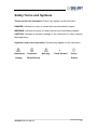
Symbols used on the instrument. Symbols may appear on the instrument:
Hazardous
Voltage
Protective
Earth Ground
SDG5000 Service Manual
Warning
Earth Ground
Power
Switch
III
Overview for the Document
The document is for SDG5000 series arbitrary waveform generator, which will
be mostly written as generator for short in the following text. The main contents
described in this manual are:
SDG5000 Series Generator at a glance
This part introduces the main technology characteristics for SDG5000
generator.
The Front Panel at a glance
This part introduces briefly all the buttons and the knob on the front panel.
The Rear Panel at a glance
This part introduces all the ports for easy communication on the rear panel.
Specifications
Chapter 1 lists the generator’s specifications.
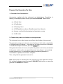
Quick Start
Chapter 2 prepares the generator for use and helps you get familiar with a few
of its front-panel features.
Calibration
Chapter 3 provides calibration, verification and adjustment procedures for the
generator.
Assembly Procedures
Chapter 4 provides disassembly procedures for you to get an understanding of
the structure of the generator, thus to install or replace some needed modules,
or troubleshoot faults you encounter while operating it.
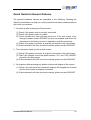
Troubleshooting
Chapter 5 provides troubleshooting procedures for the internal main board and
power supply board, as well as the quick guide for general troubles. Before any
operation, you should read the ESD Precautions to avoid personal injuries or
damages to the generator
Maintainance
Chapter 6 provides information on maintenance, daily care and unpacking
inspection of the instrument. The contact information is attached in the end in
case of some unsolvable troubles you encounter.
IV
SDG5000 Service Manual
Convention for the whole Contents
All the description for function and performance in this document are according
to SDG5162 series generator, and apply to generator of the other types. The
SDS5000 series contains the following types:
Type
Analog Bandwith
Channel
SDG5082
80 MHz
2
SDG5122
120 MHz
2
SDG5162
160 MHz
2
SDG5000 Service Manual
V
SDG5000 Series at a Glance
SDG5000 Series adopt the direct digital synthesis (DDS) technology, which
can provide stable, high-precision, pure and low distortion signals. Its
combination of excellent system features, easiness in usage and versatile
functions makes this generator a perfect solution for your testing now and in
the future.
Characteristics
Reading the characteristics and specifications given below, you will
understand how SDG5000 can satisfy your requirements.
DDS technology provides precise, stable and low distortional output signal.
4.3inch’TFT color LCD display.
500MSa/s sampling rate, 14-bit resolution.
Frequency characteristics:
Sine: 1μHz to 160 MHz
Square: 1μHz to 50 MHz
Ramp: 1μHz to 4MHz
Pulse: 1μHz to 40MHz
White Noise: 100MHz bandwidth (-3dB)
Arbitrary: 1μHz to 40MHz
5 standard waveforms: Sine, Square, Ramp, Pulse, Noise.
Self-defined arbitrary waveform.
Multiple modulation function, various modulated waveform: AM, DSB-AM,
FM, PM, ASK, FSK, PWM, Sweep and Burst.
Multiple I/O: external modulation source, external 10 MHz reference input,
external trigger source, waveform output, synchronous signal output.
Support USB storage device. Software updating could also be performed
using USB devices.
VI
Up to 512k sample points of internal waveform depth, which can rebuild or
SDG5000 Service Manual
simulate any complex waveform.
Remote control is realized using the USB cable.
Multiple interfaces: USB host & device. USB-GPIB (IEEE-488) and LAN
(option).
Support
the
seamless
connection
with
SIGLENT
Series
Digital
Oscilloscopes; Being able to directly read and rebuild the stored waveform
in the oscilloscopes.
2 languages(English and Chinese)user interface and built-in help system.
Note: All the specifications described in this manual are according to
SDG5162.
SDG5000 Service Manual
VII
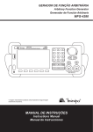
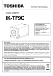
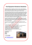
The Front Panel at a Glance
11
10
9 8
7
12
6
1
2
3
4
5
No.
Description
No.
Description
1
Power Switch
7
Universal Knob
2
LCD Display
8
Numeric Keypad
3
Menu Operation
9
Waveform Key
4
Function Keys
10
Type
5
Output Control
11
Logo
6
Direction Keys
12
USB Host
VIII
SDG5000 Service Manual
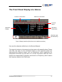
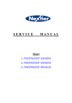
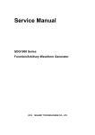
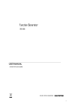
The Front Panel Display at a Glance
Channel 1 information
Channel 2 information
Function
Status
Waveform
Display
Waveform
Parameters
Waveform type
operational key
Figure1 Display Interface (Sine Wave is the default waveform)
Here are the character definitions in this Service Manual:
The signs for buttons in this manual are the same as the panel buttons. Please
note that, the signs for the functional buttons on the operation panel are
represented by squared words, such as Waveforms, which represents the
transparent functional key with Sine on it on the front panel, while the menu
buttons are represented by brighten words such as Frequency, which means
the frequency option in the Sine menu.
SDG5000 Service Manual
IX
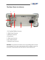
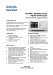
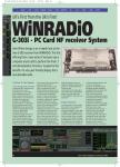
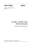
The Rear Panel at a Glance
6
5
1
2
7
3
4
1. Ext Trig/Gate/FSK/Burst Connector
2. 10MHz Output Connector
3. USB Device Connector
4. Power Socket
5. 10MHz Input Connector
6. Sync Output Connector
7. Modulation Input Connector
WARNING: For protection from electric shock, the grounding power cord must
not be defeated. If only a two-contact electrical outlet is available, connect the
instrument’s chassis ground screw (see above) to a good earth ground.
X
SDG5000 Service Manual
Contents
Guaranty and Declaration .................................................................................I
General Safety Summary.................................................................................II
Safety Terms and Symbols .............................................................................III
Overview for the Document............................................................................ IV
SDG5000 Series at a Glance......................................................................... VI
The Front Panel at a Glance ........................................................................ VIII
The Rear Panel at a Glance............................................................................ X
Specification.....................................................................................................1
Specifications.............................................................................................1
General Specifications...............................................................................7
Quick Start .......................................................................................................8
Prepare the Generator for Use ..................................................................9
Adjust the carrying Handle.......................................................................10
Set the Output Frequency........................................................................ 11
Set the Output Amplitude.........................................................................13
Set the DC offset .....................................................................................14
Set the Duty Cycle of a Square Wave......................................................15
Set the Symmetry of a Ramp Wave.........................................................16
Generate a Pulse Waveform....................................................................17
Generate a Noise Waveform ...................................................................19
Set the DC Voltage ..................................................................................21
Output a Built-In Arbitrary Waveform .......................................................22
Use the Built-In Help System...................................................................23
Calibration......................................................................................................24
Calibration Interval.............................................................................24
Adjustment is Recommended............................................................24
Automating Calibration Procedures...................................................24
Recommended Test Equipment.........................................................25
Test Considerations...........................................................................25
Performance Verification Test ..................................................................26
Self Adjust .........................................................................................26
Performance Verification Tests ..........................................................27
DC Output Verification.......................................................................28
Frequency Response Verification......................................................29
AC Amplitude Verification ..................................................................30
General Adjustment Procedure................................................................31
Warming up .......................................................................................31
Feedback Channel Adjustment..........................................................32
Channel Self Adjustment ...................................................................33
SDG5000 Service Manual
XI
Frequency Response Adjustments ....................................................34
Assembly Procedures ....................................................................................35
Security Consideration ......................................................................35
List of Modules ..................................................................................36
Required Tools...................................................................................36
Disassembly Procedures...................................................................36
A view of the whole Instrument ................................................................37
Removing the Handle ..............................................................................38
Removing the Metal Shell and Rear Cabinet...........................................39
Removing the Front Cabinet....................................................................40
Removing the Display Module .................................................................41
Removing the Main Body.........................................................................42
Troubleshooting .............................................................................................44
ESD Precautions .....................................................................................44
Required Equipments ..............................................................................44
Channel Board Drawing...........................................................................45
Main Board Drawing ................................................................................46
Check the Power Supply .........................................................................47
Check the Channel Board........................................................................49
Voltage Checking...............................................................................49
FPGA Checking.................................................................................50
Check the Main Board .............................................................................51
Voltage Checking...............................................................................51
Mainboard Clock Checking................................................................51
DSP/CPLD Checking.........................................................................52
Quick Guide for General Failures ............................................................53
Maintenance ..................................................................................................54
Maintain Summary...................................................................................54
Repackaging for Shipment.......................................................................55
Contact SIGLENT ....................................................................................56
XII
SDG5000 Service Manual
Specification
These specifications apply to SDG5000 series Arbitrary Waveform Generator.
To verify that an oscilloscope meets specifications, it must first meet the
following conditions:
The generator must have been operating continuously for fifteen minutes
within the specified operating temperature.
You must perform the Self Adjust operation, accessible through the Utility
menu, if the operating temperature changes by more than 5 °C.
The oscilloscope must be within the factory calibration interval of one year.
Specifications
Model
Maximum
frequency
output
SDG5082
SDG5122
SDG5162
80MHz
120MHz
160MHz
Output channels
2
Sample rate
500MSa/s
Arbitrary
waveform length
CH1:16kpts , CH2:512kpts
Frequency
resolution
1μHz
Vertical resolution
14 bits
Modulation
AM, DSB- AM, FM, PM, FSK, ASK, PWM, Sweep, Burst
Frequency counter
Frequency range:100mHz ~ 200MHz
Standard interface
USB Host & Device
Dimension
W x H x D=261mm x 105mm x 344mm
SDG5000 Service Manual
1
Frequency Specification
Model
SDG5082
SDG5122
SDG5162
Waveform
Sine, Square, Ramp, Pulse, Noise, Arbitrary waveform
Sine
1μHz ~ 80MHz
1μHz ~120MHz
1μHz ~ 160MHz
Square
1μHz ~ 30MHz
1μHz ~ 40MHz
1μHz ~ 50MHz
Pulse
1μHz ~ 20MHz
1μHz ~ 30MHz
1μHz ~ 40MHz
Ramp
1μHz ~ 2MHz
Gaussian Noise
100MHz (-3dB)
Arbitrary waveform
1μHz ~ 20MHz
Resolution
1μHz
Accuracy
within 1 year ±2ppm
1μHz ~ 3MHz
1μHz ~ 4MHz
1μHz ~ 30MHz
1μHz ~ 40MHz
0°C ~ 55°C
Sine Wave Spectrum Purity
Harmonic distortion
Total harmonic waveform distortion
Spurious signal(non-harmonic)
Phase noise
DC-1 MHz
<-54dBc
1 MHz - 10 MHz
<-46dBc
10 MHz - 100 MHz
<-36dBc
100 MHz - 160 MHz
<-30dBc
DC ~ 20 kHz
1Vpp <0.2%
DC ~ 1 MHz
< -70dBc
1 MHz ~ 10 MHz
<-70dBc+6dB/spectrum phase
100kHz Offset, –116dBc / Hz(typical value)
Square Wave
Rise/Fall time(10% ~ 90%)
6ns
Overshoot
< 3%
Duty
Cycle
1μHz ~ 10 MHz
20% ~ 80%
10 MHz(exclude)~ 40 MHz
40% ~ 60%
40 MHz(exclude)~ 50 MHz
50%
Asymmetric(50% Duty Cycle)
1% of Cycle + 5 ns(typical value)
Jitter (cycle to cycle)
< 100ps(typical value, rms)
Pulse Wave
Period
Maximum: 1000000s
Pulse width
≥12ns, resolution: 100ps
Rise/Fall time(10% ~ 90%)
6ns ~ 6s, resolution: 100ps
Duty Cycle
0.0001% ~ 99.9999%
Overshoot
< 3%
Jitter (cycle to cycle)
< 100ps(typical value, rms)
2
Minimum: 25 ns
SDG5000 Service Manual
Ramp Wave
Linearity
< 0.1% of output Peak value
(typical value, 1 kHz, 1Vpp, symmetric 100%)
Symmetry
0% ~ 100%
Arbitrary Waveform
Channel
CH1
CH2
Waveform length
16kpts
512kpts
Vertical resolution
14 bits
14 bits
Sample rate
500MSa/s
500MSa/s
Minimum Rise/Fall time
5ns(typical value)
5ns(typical value)
Jitter(RMS)
2ns(maximum)
2ns(maximum)
CH1
CH2
Output Characteristics
Channel
1mVpp~ 10Vpp(≤40MHz) 1mVpp ~ 10Vpp(≤40MHz)
Amplitude (50Ω)
Vertical resolution
(100 kHz sine waveform)
Amplitude flatness(based on
100kHz Sine Waveform, 1Vpp)
1mVpp~5Vpp
(40MHz~100MHz)
1mVpp~5Vpp
(40MHz~100MHz)
1mVpp~2.5Vpp
(100MHz~130MHz)
1mVpp~2.5Vpp
(100MHz~130MHz)
1mVpp ~ 1.5Vpp
(130MHz~160MHz)
1mVpp ~ 1.5Vpp
(130MHz~160MHz)
±(0.3dBm+1mVpp)
±(0.3dBm+1mVpp)
≤10MHz, ±0.1 dB
≤10MHz, ±0.1 dB
≤60MHz, ±0.2 dB
≤60MHz, ±0.2 dB
≤100MHz, ±0.4 dB
≤100MHz, ±0.4 dB
≤160MHz, ±0.8 dB
≤160MHz, ±0.8 dB
Isolate channel depth
< -80dB
Channel delay
< 1ns
DC
Output characteristic
CH1
CH2
Range(DC)
±5 V(50ohm)
±10 V(high resistance)
±5 V(50ohm)
±10 V(high resistance)
Offset accuracy
±(1%*|setting offset |+1 mV)
±(1%*|setting offset |+1 mV)
SDG5000 Service Manual
3
Waveform Output
Channel
CH1/CH2
Impedance
50Ω (typical value)
Protection
short-circuit protection
Isolation
The BNC connectors for channel output, synchronous and modulation input
are isolated to the Re Rack Earth, and the allowable voltage range is ±
42Vpk
AM/DSB-AM Modulation(CH1/CH2)
Carrier
Sine, Square, Ramp, Arbitrary(except DC)
Source
Internal/External
Modulated wave
Sine, Square, Ramp, Noise, Arbitrary
Modulation depth
0% ~ 120%
Modulation frequency
1mHz~50kHz
FM Modulation(CH1/CH2)
Carrier
Sine, Square, Ramp, Arbitrary(except DC)
Source
Internal/External
Modulation waveform
Sine, Square, Ramp, Noise, Arbitrary
Modulation frequency
1mHz ~ 50kHz
PM Modulation(CH1/CH2)
Carrier
Sine, Square, Ramp, Arbitrary(except DC)
Source
Internal/External
Modulation waveform
Sine, Square, Ramp, Noise, Arbitrary
Modulation frequency
1mHz ~ 50kHz
Phase deviation
0 ~ 360°
FSK Modulation(CH1/CH2)
Carrier
Sine, Square, Ramp, Arbitrary(except DC)
Source
Internal/External
Modulation waveform
50% duty square waveform
Key frequency
1mHz ~ 1MHz
ASK Modulation(CH1/CH2)
Carrier
Sine, Square, Ramp, Arbitrary(except DC)
Source
Internal/External
Modulation waveform
50% duty square waveform
Key frequency
1mHz ~ 1MHz
PWM Modulation (CH1/CH2)
Carrier
Pulse
Source
Internal/External
Modulation waveform
Sine, Square, Ramp, Noise, Arbitrary
Modulation frequency
1mHz ~ 50kHz
Sweep(CH1/CH2)
Carrier
4
Sine, Square, Ramp, Triangle, Arbitrary (except DC)
SDG5000 Service Manual
Type
linear/logarithmic
Direction
Up/ down
Sweep time
1ms ~ 500s ± 0.1%
Trigger source
Manual, external, internal
Burst(CH1/CH2)
Waveform
Sine, Square, Ramp, Pulse, Noise, Arbitrary (except DC)
Carrier frequency
2mHz ~ 100MHz
Type
Count(1 ~ 1000000 cycles), infinite, Gated
Start/Stop phase
0° ~ 360°
Internal cycle
1μs ~ 1000s ± 1%
Trigger delay
296ns ~ 34s
Gated source
External trigger
Trigger source
Manuel, External or Internal
External Modulation Input
Connector
The rear panel BNC connector, isolated to the Re Rack Earth
Input amplitude
± 4.5Vpk=100% modulation, input impedance >5kΩ
The external input voltage can’t be over ± 5Vpk, or the instrument will get damaged.
Trigger Input
Connector
The rear panel BNC connector, rack (reference)
Voltage level input
TTL compatible
Slope
Up or down (optional)
Pulse width
> 50 ns
Input impedance
> 5kΩ, DC coupling
Response time
380ns(typical value)
Trigger Output
Connector
The rear panel BNC connector, rack (reference)
Voltage level
TTL compatible
Pulse width
> 60ns(typical value)
Output impedance
50Ω(typical value)
Maximum frequency
1 MHz
SYNC Output
Connector
The rear panel BNC connector, isolated to the Re Rack Earth
Voltage level
TTL compatible
Pulse width
> 50 ns(typical value)
Output impedance
50Ω(typical value)
Maximum frequency
10MHz
SDG5000 Service Manual
5
REFCLK Input(10MHz ~ In)
Connector
The rear panel BNC connector, isolated to the Re Rack Earth and all the
other connectors.
Lock range
10MHz ± 50Hz
Signal level
2.3Vpp ~ 3.3Vpp
Lock Time
<2s
Input impedance
1KΩ, AC coupling
REFCLK Input(10MHz ~ Out)
Connector
The rear panel BNC connector, rack (reference)
Output frequency
10MHz
Signal level
>1Vpp
Output impedance
50Ω, AC coupling
Frequency Counter
Measurement
Frequency, Period, positive/negative Pulse Width, Duty Cycle
Frequency range
Single Channel: 100mHz ~ 200 MHz
Frequency resolution
6 bits/s
Voltage range and sensitivity(non-modulated signal)
Manual
Input adjustment
Trigger method
6
±1.5 VDC
100mHz ~ 100 MHz
50mVrms ~ ±2.5V
100 MHz ~ 200 MHz
100mVrms ~ ±2.5V
1 Hz ~ 200 MHz
100mVrms ~ 5Vpp
DC coupling
AC coupling
Pulse Width and Duty
measurement
DC deviation range
6Hz ~ 10MHz(80mVrms ~ 5Vpp)
Input impedance
1 MΩ
Coupling mode
AC/DC
HFR
On/Off
Trigger level range: -3 v ~ 1.8v
SDG5000 Service Manual
General Specifications
Display
Display type
4.3’TFT-LCD
Resolution
480×RGB×272
Color
24bit
Contrast(typical value) 500:1
Backlight
(typical )
intensity
300cd/m2
Power
Voltage
100~240 VACRMS, 45~66 Hz, CATII
100~127 VACRMS, 45~440 Hz, CATII
Power
< 30W
Fuse
1.25A, 250V
Environment
Environmental
Temperature
Operation: 0°C ~ 40°C
Cooling method
natural cooling down
Humidity range
Altitude
Non-operation: -20°C ~ 60°C
Below +35℃: ≤90% relative humidity
+35℃ ~ +40℃: ≤60% relative humidity
Operation: < 3,000m
Non-operation: <15,000m
Mechanical
Width: 261mm
Dimension
Height: 105mm
Depth: 344mm
Weight
N.W: 2.8 Kg
IP Protection
IP2X
Calibration Cycle
1 year
SDG5000 Service Manual
7
Quick Start
One of the first things you will want to do with your generator is to become
acquainted with the front panel. We have written the exercises in this chapter
to prepare the instrument for use and help you get familiar with some of its
front-panel operations. This chapter is divided into the following sections:
To Prepare the Generator for Use
To Adjust the Carrying Handle
To Set the Output Frequency
To Set the Output Amplitude
To Set a DC Offset Voltage
To Set the Duty Cycle of a Square Wave
To Set the Symmetry of a Ramp Wave
To Configure a Pulse Waveform
To Configure a Noise Waveform
To Select “DC Volts”
To Output a Built-In Arbitrary Waveform
To Use the Built-In Help System
8
SDG5000 Service Manual
Prepare the Generator for Use
1. Check the list of accessories
Accessories supplied with the instrument are listed below. If anything is
missing or damaged, please contact your nearest SIGLENT Sales Office.
A Quick Start
A Certification
A Guaranty Card
A CD(EasyWave software, DataSheet and User Manual)
A power cord that fits the standard of destination country
A USB cable
2. Connect the power cord and turn on the generator
The instrument runs a short power-on self test, which takes a few seconds.
The generator powers up in the sine wave function at 1 kHz with an amplitude
of 4Vpeak-to-peak (Channel 1). At power-on, the Output connector is disabled.
To enable the Output connector, press the Output key.
If the generator does not turn on, verify that the power cord is firmly connected
to the power socket on the rear panel (the power-line voltage is automatically
sensed at power-on). You should also make sure that the generator is
connected to a power source that is energized.
Then, verify that the generator is turned on.
Note: If the power-on self test fails, the generator may stop with black screen.
For solutions, please contact the nearest SIGLENT sales office or return the
generator to SIGLENT for service.
SDG5000 Service Manual
9
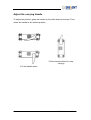
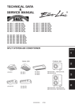
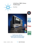
Adjust the carrying Handle
To adjust the position, grasp the handle by the sides and pull outward. Then,
rotate the handle to the desired position.
Pull the handle ahead for easy
carrying
Pull the handle down
10
SDG5000 Service Manual
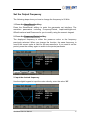
Set the Output Frequency
The following steps show you how to change the frequency to 20 KHz.
1. Press the Store/Recall softkey
Press the Store/Recall softkey to enter the parameter set interface. The
waveform parameters including Frequency/Period, Amplitude/HighLevel,
Offset/LowLevel and Phase are for you to modify using the numeric keypad.
2. Press the Frequency/Period softkey
The displayed frequency is either the power-on value or the frequency
previously selected. When you change the function, the same frequency is
used if the current value is valid for the new waveform. If you want to set the
period, press the softkey again to switch to the period parameter
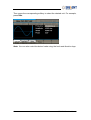
2. Input the desired frequency
Use the digital keypad to input the value directly, enter the value “20”.
SDG5000 Service Manual
11
Then press the corresponding softkey to select the desired unit. For example,
press KHz.
Note: You can also enter the desired value using the knob and direction keys.
12
SDG5000 Service Manual
Set the Output Amplitude
The following steps show you how to change the amplitude to 8Vpp.
1. Press the Ampl/HLevel softkey
The displayed amplitude is either the power-on value or the amplitude
previously selected. When you change the function, the same amplitude is
used if the current value is valid for the new waveform. If you want to set the
HLevel for the waveform, press the softkey again to switch to the HLevel
parameter.
2. Input the desired amplitude
Use the digital keypad to input the value directly, enter the value “8”.
Then press the corresponding softkey to select the desired unit. For example,
press Vpp.
Note: You can also enter the desired value using the knob and direction keys.
SDG5000 Service Manual
13
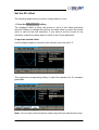
Set the DC offset
The following steps show you how to change offset to 1Vdc.
1. Press the Offset/LLevel softkey
The displayed offset is either the power-on value or the offset previously
selected. When you change the function, the same offset is used if the current
value is valid for the new waveform. If you want to set the LLevel for the
waveform, press the softkey again to switch to the LLevel parameter.
2. Input the desired offset
Use the digital keypad to input the value directly, enter the value “1”.
Then press the corresponding softkey to select the desired unit. For example,
press Vdc.
Note: You can also enter the desired value using the knob and direction keys.
14
SDG5000 Service Manual
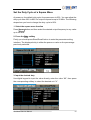
Set the Duty Cycle of a Square Wave
At power-on, the default duty cycle for square wave is 50%. You can adjust the
duty cycle from 20% to 80% for output frequencies up to 50 MHz. The following
steps show you how to change the duty cycle to 80%.
1. Select the square wave function
Press Square button and then select the desired output frequency to any value
up to 50 MHz.
2. Press the Duty softkey
Firstly you should press Store/Recall button to enter the parameter setting
interface. The displayed duty is either the power-on value or the percentage
previously selected.
.
3. Input the desired duty
Use digital keypad to input the value directly, enter the value “80”, then press
the corresponding softkey to select the desired unit “%”.
SDG5000 Service Manual
15
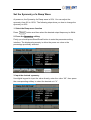
Set the Symmetry of a Ramp Wave
At power-on, the Symmetry for Ramp wave is 50%. You can adjust the
symmetry from 0% to 100%. The following steps show you how to change the
symmetry to 60%.
1. Select the Ramp wave function
Press Ramp
button and then select the desired output frequency to 4MHz.
2. Press the Symmetry softkey
Firstly you should press Store/Recall button to enter the parameter setting
interface. The displayed symmetry is either the power-on value or the
percentage previously selected.
.
3. Input the desired symmetry
Use digital keypad to input the value directly, enter the value “60”, then press
the corresponding softkey to select the desired unit “%”.
16
SDG5000 Service Manual
Generate a Pulse Waveform
You can set the generator to output a pulse waveform with variable width, edge
time and delay time. The following steps show you how to generate a 500 µs
pulse waveform with a pulse width of 100 µs, rise time of 8ns and delay time of
50 ns.
1. Select the pulse function
Press the Pulse button to select the pulse function and output a pulse
waveform with the default parameters.
2. Set the Pulse period
Press the FrequencyPeriod softkey twice and then set the period to 500 µs.
3. Set the Pulse Width
Press the Width/Duty softkey and then set the pulse width to 100 µs. The pulse
width represents the time from the 50% threshold of the rising edge to the 50%
threshold of the next falling edge.
SDG5000 Service Manual
17
4. Set the Edge Time
Press the Rise/Fall softkey and then set the rise edge to 8 ns.
5. Set the Pulse Delay
Press the Delay softkey and then set the delay time to 50 ns.
18
SDG5000 Service Manual
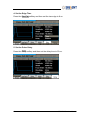
Generate a Noise Waveform
You can set the generator to output a noise waveform with Stdev and Mean.
The following steps show you how to generate a noise waveform with 500mV
Stdev and 1mV Mean.
1. Select the Noise function
Press the Noise button to select the noise function and output a noise
waveform with the default parameters.
2. Set the Stdev
Press the Stdev softkey and then set the Stdev to 500mV.
SDG5000 Service Manual
19
3. Set the Mean
Press the Mean softkey and then set the mean to 1mV.
20
SDG5000 Service Manual
Set the DC Voltage
You can set the DC Voltage feature from the Utility Menu, and then set a dc
voltage as an “Offset” value. The following steps show you how to set a dc
voltage with +1Vdc.
1. Select the Store/Recall function
Press the Store/Recall button to enter the parameter setting interface.
2. Set the DC Voltage
Press the DC button to select the DC function and output a DC waveform
with the default parameter.
3. Set the DC Offset
Press the Offset softkey and then set the offset to 1V.
SDG5000 Service Manual
21
Output a Built-In Arbitrary Waveform
There are 36 built-in arbitrary waveforms stored in non-volatile memory. The
following steps show you how to output the built-in “exponential fall” waveform
from the front panel.
1. Set the arbitrary waveform function
Press the Arb button to select the arbitrary waveform function. Then
press the Built-In softkey to enter the arbitrary waveform setting interface.
2. Set the Math waveform
Press the Math softkey to display the mathematic waveform as below.
3. Output the exponential fall waveform
Rotate the knob to select the ExpFall waveform and press the Done softkey.
The waveform is output with the present settings unless you change them.
22
SDG5000 Service Manual
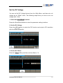
Use the Built-In Help System
The built-in help system is designed to provide context-sensitive assistance of
some functions. A list of help topics is also available to assist you with several
operations.
1. Read the help information for SDG5000
Press Help button in utility system, you will see a list of help topics as below.
With easy operations on the front panel, you could read any help item you
desired.
2. Press “Cancle” or any function button to exit the help system
SDG5000 Service Manual
23
Calibration
This calibration procedure contains performance verification procedure and
adjustment procedure. After receiving a generator, you should firstly verify if its
performance applies to the limits, and then perform adjustment in case of
abnormal testing results.
Calibration Interval
The instrument should be calibrated on a regular interval determined by the
measurement accuracy requirements of your application. A 1-year interval is
adequate for most applications. Accuracy specifications will remain valid only if
adjustment is made at regular calibration intervals. Accuracy specifications are
not valid beyond the1-year calibration interval. SIGLENT does not recommend
extending calibration intervals beyond 2 years for any application.
Adjustment is Recommended
Specifications are valid only within the period from the last adjustment.
Whatever calibration interval you select, SIGLENT recommends that
re-adjustment should always be performed within the calibration interval. This
is necessary to ensure the accuracy of the performance data measured during
the calibration interval.
Automating Calibration Procedures
You can automate the complete verification and adjustment procedures
outlined in this chapter if you have access to programmable test equipment.
You can program the instrument configurations specified for each test over the
remote interface. You can then enter read-back verification data into a test
program and compare the results to the appropriate test limit values.
You can also adjust the instrument from the remote interface. Remote
adjustment is similar to the local front-panel procedure. You can use a
computer to perform the adjustment by first selecting the required function and
range. The adjustment command is sent to the instrument and then the
adjustment is initiated over the remote interface.
24
SDG5000 Service Manual
Recommended Test Equipment
The test equipment recommended for the performance verification and
adjustment procedures is listed below. If the exact instrument is not available,
substitute calibration standards of equivalent accuracy.
Instrument
Digital Multimeter(DMM)
Power Meter
GPIB cable
Frequency Counter
Digital Oscilloscope
Requirements
dc volts
accuracy: 100ppm
resolution: 100μV
Frequency:
10KHz to 50MHz
Recommended Model
Agilent 34401A
Agilent U2004
GPIB(IEEE488)
Accuracy: 1ppm
200MHz Bandwidth
Agilent DSOX3024A
Test Considerations
For optimum performance, all procedures should comply with the following
recommendations:
Assure that the calibration ambient temperature is stable and between 18
℃ and 28℃. Ideally, the calibration should be performed at 23℃±1℃.
Assure ambient relative humidity is less than 80%.
Allow a half an hour warm-up period before verification or adjustment.
Keep the measurement cables as short as possible, consistent with the
impedance requirements.
Use a 50Ω cable.
SDG5000 Service Manual
25
Performance Verification Test
Use the performance verification tests to verify the measurement performance
of the instrument. The performance verification tests use the instrument’s
specifications listed in the “Specifications” chapter.
You can perform two different levels of performance verification tests:
Self Adjust A series of internal verification tests that give high confidence
that the instrument is operational.
Performance Verification Tests An extensive set of tests that are
recommended as an acceptance test when you first receive the instrument
or after performing adjustments.
Self Adjust
A brief power-on Self Test occurs automatically whenever you turn on the
instrument. This limited test assures that the instrument is operational.
To perform a complete self Adjust:
1. Press Utility button on the front panel and enter to page 2.
2. Select the Test/Cal softkey, and then select the Self Adjust softkey.
The instrument will automatically perform the complete Self Adjust procedure
when you release the key. The Self Adjust will complete in approximately 20
seconds.
There is a progress bar show on the screen during the Self Adjust.
If the Self Adjust is successful, “100%” is displayed over the progress bar.
If the Self Adjust fails, the progress halts at some values.
If repair is required, see chapter 5, “Troubleshooting”, for further details.
26
SDG5000 Service Manual
Performance Verification Tests
The performance verification tests are recommended as acceptance tests
when you first receive the instrument. The acceptance test results should be
compared against the specifications given in chapter 1. After acceptance, you
should repeat the performance verification tests at every calibration interval.
If the instrument fails performance verification, adjustment or repair is required.
Adjustment is recommended at every calibration interval. If adjustment is not
made, you must guard band, using no more than 80% of the specifications
listed in chapter 1, as the verification limits.
SDG5000 Service Manual
27
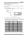
DC Output Verification
This test checks if the DC offset listed in the table below are within the spec
range using a DMM.
1. Set the DMM to measure DC voltage. Connect the DMM to the channel 1
output of the generator as shown below.
2. Turn on channel 1 and select DC system under the Utility menu.
3. Set the instrument to each output value described in the table below and
measure the output voltage with the DMM. Be sure the generator output
impedance is set to High–Z and the output is enabled.
DC Offset
0mv
10mv
100mv
1v
3v
10v
-10mv
-100mv
-1v
-3v
-10v
CH1
CH2
Spec Range
± (1%+3mv)
-1mv ~ 1mv
8.9mv ~ 11.1mv
98mv ~ 102mv
0.989v ~ 1.011v
2.969v ~ 3.031v
9.899 ~ 10.101
-11.1mv ~ - 8.9mv
-102mv ~ 98mv
-1.011v ~ 0.989v
-3.031v ~ 2.969v
10.101v ~ 9.899v
4. Compare the measured voltage to the spec range shown in the table above.
28
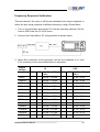
SDG5000 Service Manual
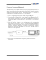
Frequency Response Verification
This test checks if the value in dB format translated from output amplitude is
within the spec range response to different frequency using a Power Meter.
1. Turn on the generator and choose CH1 as the operating channel. Set the
Load to 50Ω under the CH1/CH2 menu.
2. Connect the Power Meter, PC and generator as shown below.
3. Select Sine waveform of the generator and set the amplitude to 1V and
2.5V, frequency to the values listed below in sequence.
Output
Voltage
Frequency CH1
1V
10KHz
the Spec Range CH1 CH2 the Spec Range
(dBm)
(dBm)
3.8794 ~ 4.0794
11.84 ~12.04
100KHz
3.8794 ~ 4.0794
11.84 ~12.04
1MHz
3.8794 ~ 4.0794
11.84 ~12.04
5MHz
3.8794 ~ 4.0794
11.84 ~12.04
10MHz
3.8794 ~ 4.0794
11.84 ~12.04
20MHz
3.7794 ~ 4.1794
11.74 ~12.14
30MHz
3.7794 ~ 4.1794
11.74 ~12.14
50MHz
3.7794 ~ 4.1794
11.74 ~12.14
80MHz
3.5794 ~ 4.3794
11.54 ~12.34
100MHz
3.5794 ~ 4.3794
11.54 ~12.34
110 MHz
3.1794 ~ 4.7794
11.14 ~12.74
120 MHz
3.1794 ~ 4.7794
11.14 ~12.74
160MHz
3.1794 ~ 4.7794
11.14 ~12.74
SDG5000 Service Manual
CH2
2.5V
29
4. Remove the BNC cable to CH2 output and perform the same verification as
channel1.
5. Compare the value measured from Power Meter to the spec range shown in
the table above.
AC Amplitude Verification
This test checks the ac amplitude output accuracy at the frequency of 100 kHz
using a Power Meter.
1. Turn on the generator and choose CH1 as the operating channel. Set the
Load to 50Ω under the CH1/CH2 menu.
2. Connect the Power Meter, PC and generator as shown below.
3. Select Sine waveform of the generator and set the amplitude to the values
listed below in sequence.
Amplitude
CH1 (dBm)
CH2 (dBm)
the Spec Range (dBm)
40mv
-24.50 ~ -23.46
200mv
-10.34 ~ -9.65
500mv
-2.35 ~ -1.72
2v
9.69 ~ 10.3
5v
17.65 ~ 18.26
4. Remove the BNC cable to CH2 output and perform the same verification as
channel1.
5. Compare the value measured from Power Meter to the spec range shown in
the table above.
30
SDG5000 Service Manual
General Adjustment Procedure
This chapter explains how to adjust the SDG5000 series generator for
optimum operating performance. The following contents are the three
adjustment steps:
Feedback channel Adjustment which act as a standard calibration
module, providing the accuracy assurance for Self Adjust.
Channel Self Adjustment which includes internal control channel
adjustment and signal channel adjustment.
Frequency Response Adjustment which could properly compensate the
amplitude as the frequency increases.
Warming up
Before performing the adjustment procedures, you must let the oscilloscope
and other test equipments warm up for at least 15 minutes in an ambient
temperature between 20 °C and 30 °C. Adjustments performed prior to
warm-up or outside this temperature range may result in poor performance.
SDG5000 Service Manual
31
Feedback Channel Adjustment
The internal feedback channel receives the feedback signal from all the other
channels that are performing self adjustment. This adjustment acts as a
standard test module and must be performed prior to Self Adjust to make sure
it is performed based on a best adjusting accuracy.
1. Turn on the generator.
2. Connect the DMM, PC and SDG5000 generator as shown below:
3. Open the EasyTest software on the desktop, and run the feedback channel
script prepared previously. The CH2 will be automatically turned on upon
running of the script.
32
SDG5000 Service Manual
Channel Self Adjustment
This adjustment is for internal control channel and signal channel. Through
feedback circuits of the feedback channel and signal channel, this adjustment
helps to obtain the actual working performance for components from signal
channels.
1. After the feedback channel adjustment completed, disconnect the two BNC
cables on channel 1 and channel 2.
2. Select “Self Adjust” to perform the channel Self Adjustment in Test/Cal
system under the Utility menu.
3. Once the “Self Adjust” begins, the generator turns to adjustment interface
and the progress bar displays on the screen. In about 15 seconds it will
reach to 100%, which indicates completing of the self-adjust. You could
press any functional button to exit.
SDG5000 Service Manual
33
Frequency Response Adjustments
This adjustment aims to obtain the actual frequency response characteristic of
signal channel, thus to perform appropriate compensation. Since the waveform
amplitude will decrease as the input frequency increases, it is essential to
compensate for the amplitude to match it to the frequency.
1. Turn on the generator and connect it to PC using a USB cable.
2. Connecting the USB end of the Power Meter to the USB port of the PC,
upon which the Power Meter indicator light will be brightened. Only after the
indicator light goes out from red, could it be connected to the generator
output.
3. Open the EasyTest software on the desktop, and run the corresponding
script prepared previously. In about 10 seconds the prompt message will
display on the screen to indicate you to connect the Power Meter. After the
generator completes adjustment for channel 1, the prompt message
displays on the screen will indicate you to remove the BNC cable to
channel 2 to start adjustment.
4. After the two channel adjustment completed, please disconnect all
connections.
34
SDG5000 Service Manual
Assembly Procedures
This chapter describes how to remove the major modules from the SDG5000
series generator. To install the removed modules or replace new modules,
please follow corresponding operating steps in reverse order.
The following contents are what mainly included in this chapter:
Security Consideration which describes security information needed to
considerate while operating.
List of Module in which the modules to remove are listed.
Required Tool which describes the tools needed to perform the
procedures
Disassembly Procedures which describes in detail how to remove and
install the modules
Security Consideration
Only qualified personnel should perform the disassembly procedures.
Whenever possible, disconnect the power before you begin to remove or
replace the modules. Otherwise, any personal injuries or damages to the
components may occur.
Avoid Electric Shock Hazardous voltages exist on the LCD module and
power supply module. To avoid electrical shock, you should firstly disconnect
the power cord from the oscilloscope, and then wait at least three minutes for
the capacitors in the oscilloscope to discharge before you begin disassembly.
Preventing ESD Almost all electrical components can be damaged by
electrostatic discharge (ESD) during handling. Component damages can occur
at electrostatic discharge voltages as low as 50 volts. The following guidelines
will help preventing ESD damage when servicing the instrument or any
electronic device.
Disassemble instruments only in a static-free work area.
Use a conductive work area to reduce static charges.
Use a conductive wrist strap to reduce static charge accumulation.
SDG5000 Service Manual
35
Minimize handling.
Keep replacement parts in original static-free packaging.
Remove all plastic, foam, vinyl, paper and other static-generating materials
from the immediate work area.
Use only anti-static solder suckers.
List of Modules
The following removable modules are listed in the order of performing
disassembly procedures.
Number of Module
Module
1
Handle
2
Metal Shell and Rear Cabinet
3
Front Cabinet
4
Display Module
5
Main Body
Required Tools
Use the tool to remove or replace the modules in the oscilloscope:
PH2 phillips screwdriver
Disassembly Procedures
This section describes how to remove and install the modules listed above in
the generator in detail. Complete disassembly will be best achieved through
the following operating steps.
36
SDG5000 Service Manual
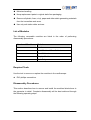
A view of the whole Instrument
The disassembly drawing are shown as below for you to disassemble the
generator in right steps. Before disassembling, please cut the power to avoid
any personal injuries or damages to inside components. Since some modules
of the instrument are sharp, you should also take care while operating to
prevent being scratched.
Table 4-1 A view of the whole instrument
SDG5000 Service Manual
37
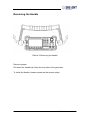
Removing the Handle
Table 4-2 Removing the handle
Removing steps:
Pull down the handle hard from the two sides of the generator.
To install the handle, please operate as the reverse steps.
38
SDG5000 Service Manual
Removing the Metal Shell and Rear Cabinet
Rear Cabinet screw
Table 4-3 Removing the Metal Shell and Rear Cabinet
Removing steps:
1. Remove the two screws from the rear cabinet of the generator using a PH2
phillips screwdriver.
2. Remove the rear cabinet.
3. Remove the metal shell carefully from the main body to avoid being
scratched.
To install the metal shell and rear cabinet, please operate as the reverse steps.
SDG5000 Service Manual
39
Removing the Front Cabinet
Front Cabinet screw
BNC Connector
Table 4-4 Removing the Front Cabinet
Removing steps:
1. Remove the four front cabinet screws using the PH2 screwdriver.
2. Firmly pull up the two screws connected to the main board from the front
panel BNC connectors.
3. Disconnect the display module cable and the USB module cable from the
main board.
4. Separate the front cabinet from the main body of the generator.
To install the front cabinet, please operate as the reverse steps.
40
SDG5000 Service Manual
Removing the Display Module
USB screw
Keypad Board screw
Metallic Support screw
Table 4-5 Removing the display module screws
Removing steps:
1. Remove the six screws fixed the keypad circuit board using the PH2 screw
driver.
2. Remove the two screws fixed the USB module using the PH2 screwdriver.
3. Remove the four screws fixed the metallic support using the PH2
screwdriver.
4. Remove the keypad circuit board, silica gel soft keypad, metallic support
and LCD screen from the front cabinet in sequence.
5. Remove the front cabinet universal knob by firmly pull it out.
To install the display module, please operate as the reverse steps.
SDG5000 Service Manual
41
Removing the Main Body
Table 4-6 Disconnecting all the cables
Table 4-7 Removing all the screws
42
SDG5000 Service Manual
Removing steps:
1. Disconnect all cables from the main board and power supply board.
2. Remove all the 20 screws fixed the main board and power supply board
using a the PH2 screwdriver.
3. Separate the main board and power supply board carefully from the main
body of the generator to avoid being scratched by the sharp metal edge.
To install the main body, please operate as the reverse steps.
SDG5000 Service Manual
43
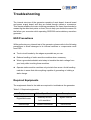
Troubleshooting
The internal structure of the generator consists of main board, channel board
and power supply board, and they are linked through cables or connectors.
This chapter explains the main checking procedures for these three boards by
measuring the rated test points on them, thus to help you decide the reason for
the failure you encounter while operating SDG5000 series arbitrary waveform
generator.
ESD Precautions
While performing any internal test of the generator, please refer to the following
precautions to avoid damages to its internal modules or components result
from ESD.
Touch circuit boards by the edges as possible as you can.
Reduce handling of static-sensitive modules when necessary.
Wear a grounded antistatic wrist strap to insulate the static voltage from
.
your body while touching these modules.
Operate static-sensitive modules only at static-free areas. Avoid handling
modules in areas that allow anything capable of generating or holding a
static charge.
Required Equipments
The equipments listed in the table are required to troubleshoot the generator.
Table 5-1 Required equipments
Equipment
Critical Specifications
Example
Accuracy ±0.05%
Agilent 34401A
Digital Multimeter
1 mV resolution
Oscilloscope
44
200MHz Bandwidth
DSOX3024A
SDG5000 Service Manual
Channel Board Drawing
Channel board is a kind of signal conditioning board for output analog signal. It
mainly works on the adjusting of signal parameters such as frequency,
amplitude. Please refer to the following drawing to quickly locate the test points
on the channel board for easy resolution of the failures you encounter.
SDG5000 Service Manual
45
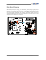
Main Board Drawing
Main board is used to control and manage the whole internal system of the
generator. It completes the GUI function, controlling and configuration function
for channel board as well as man-machine interaction. Please refer to the
following drawing to quickly locate these test points on the main board for easy
resolution of the failures you encounter.
46
SDG5000 Service Manual
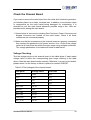
Check the Power Supply
There are two power connectors through which the channel board and main
board can be supplied electricity. For the channel board, there are four voltage
test points on its power connector. For the main board, there is one test point.
Before performing the power supply testing procedure, please make sure that
the generator is grounded correctly through the protective lead of the power
cord. Take care not to touch or even disassemble the power supply module
without any safety precautions, or you may probably suffer from electric shock
or burn. Here are procedures for testing the power supply:
1. Disconnect the power cord of the generator and then check whether the
fuse has been burnt out.
2. Remove metal shell of the generator using a driver, and then disconnect the
power connector connected to the main board.
3. Focus on the Power Connector for channel board, which contains 6 pins
from Pin1 to Pin6. Since two of the six pins are ground wire, you can test the
other four pins that are marked with blue, yellow, red and white to check
whether the voltage value is within the corresponding specified range using
a digital multimeter. The voltage parameters to be tested are listed in table
below:
Table 5-2 Test voltages for the channel board power connector
Voltage value
Pins
Error limit
15.5V
VH+(red)
±5%
-16.5V
VH-(white)
±5%
5.5V
VL+(yellow)
±5%
-6.5V
VL-(blue)
±5%
Table 5-3 Test voltage for the main board power connector
Voltage value
Pins
Error limit
6.5V
VH+(red)
±5%
If each tested voltage value is within the corresponding spec range referring to
the table above, then the power supply works normally. Otherwise, it proves to
be faulted, please return it to the factory to have it repaired or contact
SIGLENT.
SDG5000 Service Manual
47
Note: The main power supply provides an input fuse to protect against the
danger of fire in the event of a failure of the power supply circuitry. However,
this fuse will not fail ("open" or "blow") in normal power supply operation except
that a significant overload occurs. Replace the entire main power supply
assembly if the input fuse fails.
48
SDG5000 Service Manual
Check the Channel Board
If you want to remove the main board from the metal shelf inside the generator,
you’d better place it on a clean, insulated mat. In addition, to avoid some chips
or components on the main board being damaged for overheating, it is
essential to cool the main board whenever possible using a fan. Here are
procedures for testing the main board:
1. Several kinds of connectors including Fan Connector, Power Connector and
Keypad Connector are located on the main board. Check if all these
connectors are connected properly.
2. Make sure that the connectors on the channel board are properly connected,
then connect the generator to AC power and turn it on. Check if the voltage
values at all test points are within the spec range using a digital multimeter.
The voltage parameters to be tested are listed in table below:
Voltage Checking
Test the voltage points on the channel board in the table below. If each tested
voltage value is within the corresponding spec range referring to the table
above, then the main board works normally. Otherwise, it proves to be faulted,
please return it to the factory to have it repaired or contact SIGLENT.
Table 5-3 Test voltages of the channel board
Test point
Voltage value
Error limit
+15V
+15V
±5%
-15V
-15V
±5%
-5V
-5V
±5%
+5V
+5V
±5%
VCC3.3V
+3.3V
±5%
VCC5V
+5V
±5%
VCC1.8V
+1.8V
±5%
VCC1.2V
+1.2V
±5%
FAN_12V
+12V
±5%
PLL_3.3V
+3.3V
±5%
SDG5000 Service Manual
49
FPGA Checking
To check if the FPGA works normally, please look at the test point marked with
FPGA_LED on the channel board drawing. The LED light twinkles at the
frequency of 1Hz in normal case, if it can not be lighted or twinkles at incorrect
frequency, then the FPGA may be faulted.
50
SDG5000 Service Manual
Check the Main Board
If you want to remove the main board from the metal shelf inside the generator,
you’d better place it on a clean, insulated mat. In addition, to avoid some chips
or components on the main board being damaged for overheating, it is
essential to cool the main board whenever possible using a fan. Here are
procedures for testing the main board:
1. Several kinds of connectors including Fan Connector, Power Connector and
Keypad Connector are located on the main board. Check if all these
connectors are connected properly.
2. Make sure that the connectors on the main board are properly connected,
then connect the generator to AC power and turn it on. Check if the voltage
values at all test points are within the spec range using a digital multimeter.
The voltage parameters to be tested are listed in table below:
Voltage Checking
Test the voltage points on the main board in the table below. If each tested
voltage value is within the corresponding spec range referring to the table
above, then the main board works normally. Otherwise, it proves to be faulted,
please return it to the factory to have it repaired or contact SIGLENT.
Table 5-4 Test voltages of the main board
Test point
Voltage value
Error limit
+16V
+16V
±5%
3.3V
+3.3V
±5%
VCC5V
+5V
±5%
VCC1.2V
+1.2V
±5%
Mainboard Clock Checking
Mainboard clock is the internal system clock of the generator. To verify if the
clock on the main board works normally, please test the clock frequency listed
below using an oscilloscope.
Test point
Frequency
Stability
Clock_25MHz
25MHz
±50ppm
SDG5000 Service Manual
51
DSP/CPLD Checking
DSP and CPLD respectively represent the main control chip and
programmable logic device of the main board. Only when the corresponding
codes loaded successfully, can the two chips work normally.
Look at the DSP_LED/CPLD_LED light on the main board, which indicates the
working state of DSP/CPLD chip. If the light turns on, then the corresponding
codes have been loaded successfully and the chip is in good working state.
Otherwise, there may be failure within it.
52
SDG5000 Service Manual
Quick Guide for General Failures
The general hardware failures are described in the following. Reading the
following information can help you quickly handle some easy hardware failures
with more convenience.
1. No start-up after pressing the Power button:
(1) Check if the power cord is correctly connected.
(2) Check if the power button is usable.
(3) Check whether the fuse has been burnt out. If the fuse needs to be
changed, please contact SIGLENT as soon as possible and return the
instrument to the factory to have it repaired by qualified personnel.
(4) Check if the power connector is properly connected to the main board.
(5) If the instrument still does not work normally, please contact SIGLENT.
2. The instrument starts up with a dark screen:
(1) Check if the power connector is properly connected to the main board.
(2) Test if the voltages on the test points marked “-5V” and “LED_ANODE”
are within the spec range.
(3) If the instrument still does not work normally, please contact SIGLENT.
3. No response after pressing any button or abnormal display of the screen:
(1) Check if the two end of the connector between the keypad circuit board
and the main board is properly connected.
(2) If the instrument still does not work normally, please contact SIGLENT.
SDG5000 Service Manual
53
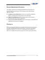
Maintenance
Maintain Summary
SIGLENT warrants that the products it manufactures and sells are free from
defects in materials and workmanship for a period of three years from the date
of shipment from an authorized SIGLENT distributor. If a product or CRT
proves defective within the respective period, SIGLENT will provide repair or
replacement as described in the complete warranty statement.
To arrange for service or obtain a copy of the complete warranty statement,
please contact your nearest SIGLENT sales and service office.
Except that as provided in this summary or the applicable warranty Statement,
SIGLENT makes no warranty of any kind, express or implied, including without
limitation the implied warranties of merchantability and fitness for a particular
purpose. In no case shall SIGLENT be liable for indirect, special or
consequential damages.
54
SDG5000 Service Manual
Repackaging for Shipment
If the unit needs to be shipped to SIGLENT for service or repair, be sure to:
1. Attach a tag to the unit identifying the owner and indicating the required
service or repair.
2. Place the unit in its original container with appropriate packaging material
for shipping.
3. Secure the container with strong tape or metal bands.
If the original shipping container is not available, place your unit in a container
which will ensure at least 4 inches of compressible packaging material around
all sides for the instrument. Use static-free packaging materials to avoid
additional damage to your unit.
SDG5000 Service Manual
55
Contact SIGLENT
SIGLENT TECHNOLOGIES CO., LTD
Address:3/F, building NO.4, Antongda Industrial Zone, 3rd Liuxian
Road, Bao’an District, Shenzhen, P.R.China
Tel:0086-755-3661 5186
E-mail:[email protected]
http://www.siglent.com
56
SDG5000 Service Manual