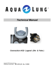
1
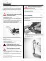
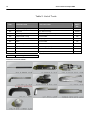
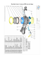
FIRST TO DIVE
SERVICE MANUAL
Octopus ABS
Copyright ©11- 2004 Aqualung France
Rev. 1/2004
2
Service manual Octopus ABS
Index
COPYRIGHT............................................................................................................................... 3
INTRODUCTION........................................................................................................................ 3
WARNINGS, ATTENTION, NOTE...……………........................................................................ 3
MAINTENANCE.......................................................................................................................... 3
GENERAL INSTRUCTIONS.....................……........................................................................... 3
GENERAL CONVENTIONS….................................................................................................... 4
DISASSEMBLY PROCEDURE…................................................................................................4
REASSEMBLY PROCEDURE......…...........................................................................................6
FINAL ASSEMBLY.....................................................….................................................….........7
Table 1. Troubleshooting guide................................................…............................…................9
Table 2. List of tools..........................................………........................…….....…………………..10
Table 3. Recommended cleaners and lubricants...............................................................…..... 11
Procedure A. Cleaning and lubricating........................................................................................12
Table 4. Torque settings..........................................................................................………........ 13
Table 5. Checking specifications..............................................................................……............13
Exploded view........................……………………………..............................................................15
F I R S T
T O
3
D I V E
COPYRIGHT
This manual is the property of Aqualung France. Any
copying, photocopying, reproduction, translation, electronic
distribution (email, Internet...), even partial, and in whatever
format, is expressly forbidden without the written consent of
Aqualung France.
GENERAL INSTRUCTIONS
1.
In order to carry out the procedures described in this
manual correctly it is important that you follow the steps
in the exact order indicated. Read the manual through
completely so that you become familiar with all the
procedures, the special tools and the replacement parts,
before starting to disassemble the product. Keep this
manual open near to you so that you can refer to it step
by step. Do not rely on your memory..
2.
All servicing and repair procedures should be carried
out in a workshop that is clean, well lit, easy to access
and specially fitted for the purpose.
3.
The regulator body should never be directly held in the
jaws of a vice. To hold the body, screw the tool 006230
into the HP port and then grip the tool with the vice.
4.
Once the regulator has been disassembled, the reusable components should be separated from the
components that need to be replaced. Fragile items with
seats or crowns with critical sealing surfaces should be
separated and protected during servicing in order to
prevent any damage.
5.
Use only spare parts from Aqualung service kits. Never
replace an Aqualung part with one from another
manufacturer, even if it appears similar.
6.
Never re-use regulator parts which should be replaced
on the pretext that the regulator has seen little use since
its manufacture or since its last service.
7.
When reassembling, check that the torque used
conforms with that shown in Table 4, Torque. Some
parts can be irretrievably damaged if the acceptable
torque is exceeded.
©2004 Aqua Lung France.
INTRODUCTION
This manual gives the instructions and the recommendations
for the disassembly, the cleaning, the checking, the
reassembly and the adjustment of an Aqualung regulator.
This manual is not an instruction manual for unqualified
personnel. The procedures described in this manual are
intended only for qualified personnel who have been trained
in the servicing of Aqualung equipment during a specialised
course.
If you do not understand certain procedures in this manual
you should contact an Aqualung service consultant before
undertaking any operation.
WARNINGS, ATTENTION, NOTES
Certain icons have been used to facilitate the reading and
understanding of this manual. They have the following
meanings :
.
WARNING: Indicates situations that could result in
serious or fatal accidents if the advice given is not
followed correctly.
.
ATTENTION: Indicates a situation or action that
could cause serious damage to the product,
making it dangerous if the advice given is not
followed correctly.
NOTE : Notes are used to emphasize
important points as well as information which
needs to be remembered.
MAINTENANCE
Attention: Whatever the number of dives
carried out during a year, the regulator should
receive a complete service each year. If the
regulator is used in a chlorinated or
aggressive environment the service period
should be reduced to six months.
In order to conform with the Aqualung Regulator
Lifetime Guarantee, all servicing (inspection, servicing
and repairs) should be recorded in the Service Record
incorporated in the regulator User Manual.
GENERAL CONVENTIONS
The conventions described below define the actions to be
carried out when an instruction is given.
1.
Unscrew: to unscrew a threaded part, turn it anticlockwise.
2.
Screw: to screw a threaded part, turn it clockwise.
3.
Remove the O-ring: To remove an O-ring follow the
method below, using the special tool provided for this
purpose. Any tool that could damage the O-ring should
be avoided. In every case, replace the O-ring removed
with a new one.
Press simultaneously on the
two sides of the O-ring in
order to form an ‘eye’. .
Insert the special tool into this
eye to remove the O-ring.
4
4.
5.
Service manual Octopus ABS
The acronyms used:
LP: Low Pressure
MP: Medium Pressure
HP: High Pressure
Numbers in brackets indicate the part number of the
component shown on the exploded view attached.
1. Block the crown holder (12) using a 19mm spanner and
unscrew the hose with a 11/16" spanner. Remove the hose
and then remove its O-rings
2. Cut the collar (23) using wire snips and remove the
mouthpiece (22) from the casing (19). Check that the
mouthpiece has no holes or defects.
DISASSEMBLY PROCEDURE
Note: Before commencing disassembly, consult
the exploded view to check the reference
numbers of all parts requiring replacement.
These parts should all be replaced by new parts
and should not be re-used on the pretext that
the regulator has seen little use since its
manufacture or since its last service.
Attention: Use only the special tool when
removing O-rings in order to avoid damaging the
seal recess. The slightest scratch on a sealing
surface could cause a leak. If a surface should be
damaged then this part should be replaced with a
new one. Do not use any pointed instrument or
metal tool to remove O-rings.
3. Hold the casing (19) firmly and unscrew the ring cover
(14) using tool 129198.
4. Remove the purge button (15), check that it has no cuts or
defects.
5. Use tool 129198 (or A00188) to unscrew the diaphragm
screw (15)
F I R S T
T O
5
D I V E
6. Hold the casing (19) down firmly and unscrew the crown
holder (12) with a 19mm spanner. Remove the O-ring (11)
from the crown holder (12)
12. Check the condition of the lever (3), it should not be
deformed or corroded
7. Using a screwdriver, unscrew the seat (21) 6 or 7 turns
Note: As the crown is fitted with an O-ring it may
not fall out of the crown holder. It can be
extracted using the tool 116236, to avoid
damaging the sealing surface.
8. Insert tool 116236 into the insert, on the side opposite the
hose, push the crown out. Remove the O-ring (20)
13. Check the condition of the spring (6), it should not be
deformed or corroded
14. Using the O-ring tool, prick the centre of the seat (8) and
extract the seat from the poppet (7). Keep the seat as it can
be useful during reassembly.
NOTE: The old HP seat can be useful during
the reassembly of the Octopus. Put it aside for
this purpose.
15. Place the handle of tool 116236 directly against the
square poppet holder (5) and press until the poppet holder
falls out.
9. Examine the crown with a magnifying glass to check that
its sealing surfaces are all in good condition.
10. Push the insert assembly (4) into the casing inserting the
index into the bump on the casing.
Remove the insert assembly (4) by holding the lever (3).
11. To separate this assembly, screw the crown holder (12)
into the insert (4).
Using a 6.35 mm spanner, unscrew the Nylstop screw (1).
Remove the washer (2) and the lever (3) from the insert.
Unscrew the crown holder (12) to allow the poppet (7) and
the spring (6) to be removed.
16. To remove the two exhaust valves you should first
remove the grid (10). Insert the blade of a small screwdriver
into one of the two slits in the casing (19) and push the
screwdriver in until the grid clip is released. Repeat the
operation for the second clip.
6
Service manual Octopus ABS
2. Fit the O-ring (20) onto the seat (21). Insert the crown into
the crown holder (threaded part first) from the hose
connection side.
Push the seat home using the handle of tool 116236.
END OF DISASSEMBLY
Before starting to re-assemble
the Octopus, make sure that all
replacement parts have been
cleaned
and
lubricated
in
accordance with Procedure A :
Cleaning and Lubricating on
page 13.
3. Use a screwdriver to screw the seat (21) into the crown
holder. Screw it in completely and then unscrew it two and a
half turns.
4. Place the crown holder upright on a flat surface, the
seat’s sealing surface uppermost. Fit the O-ring (11) in the
groove at the base of the threaded part.
5. Place the old seat removed during disassembly onto the
sealing surface.
RE-ASSEMBLY PROCEDURE
NOTE: Before starting reassembly, it is
important to check all the parts. All old and
new parts should be perfectly clean and free of
any dust or rust.
1. Fit the two exhalation valves (9), pass the valve tail
through the hole in the casing from the outside and pull
gently until the notch is inside the casing. If it is a new valve
cut off any excess tail leaving about 5mm. Repeat for the
second valve.
Engage the two upper grid clips (10) in the two upper slits in
the casing. Engage the two lower clips and press on the
bottom of the grid next to the two clips.
6. Fit the square poppet holder (5) onto the rod of the tool
116236, square side upwards.
Engage the tool into the insert (4) and across the centre
square. Align the square section of the holder with the
square recess in the insert and push with the tool to engage
the holder into the insert. After assembly the square holder
should be at the same level as the insert.
F I R S T
T O
7
D I V E
7. Fit the seat (8) into the seat holder (7).
8. Fit the spring (6) onto the tail of the seat holder (7)
9. Insert the poppet and its spring into the seat holder and
screw in the insert (4) to compress the spring. Continue to
screw in until the threaded part of the poppet emerges from
the insert.
Attention: If resistance is felt while screwing
in, step and unscrew a little to ensure that the
square sections of the crown holder and the
poppet holder are aligned.
10. Position the insert assembly and turn it so that the
injection hole is at 8 o’clock.
Put the lever into the groove on the insert, with the rounded
part of the lever uppermost.
11. Place the washer (2) onto the tail of the poppet, then the
Nylstop screw with its flat side downwards. Screw the
Nylstop in by hand to engage the thread, then continue using
a 6.35mm spanner until the first thread appears.
12. Hold the insert and the lever and unscrew the crown
holder (12). Check that the lever feet have not come out of
the groove.
Remove the old seat (8).
13. After removing the old seat (8) screw the crown holder
(12) back in to the insert (4)
Tighten the crown holder by hand.
NOTE: The preliminary reassembly of the
Octopus ABS is now complete. Do not
continue reassembly until you have adjusted
the insert assembly using the following procedure.
Attention: Bad adjustment of the Nylstop
screw can overload the screw in the Octopus,
which could degrade performance.
1. Screw in the Nylstop using a 6.35mm hex spanner until a
slight leak is heard.
2. Press lightly on the lever several times to induce airflow.
3. Unscrew the Nylstop ¼ turn.
4. Press lightly on the lever several times to induce airflow to
check that there are no leaks.
Attention: Overtightening the Nylstop can
cause a slight withdrawal of the poppet from
the seat. Do not correct this defect by
screwing in the seat.
7. Turn off the air supply to the regulator, purge the circuit by
pushing gently on the lever.
Remove the adjustment tool.
8. Unscrew the seat from the insert while pressing on the
lever.
Final Assembly
1. Place the insert assembly into the casing with the lever
pointing upwards.
Introduce the insert assembly into its position in the casing
until the threaded female part of the insert is just visible
outside the casing.
2. While holding the lever down, manually screw the seat into
the casing.
While holding the lever down, use a 19mm torque wrench to
screw in the seat at 1m.Kg.
8
Service manual Octopus ABS
3. Fit the diaphragm and the washer into the casing.
4. Screw in the diaphragm retainer (15) using the spanner
129198 (or A00188).
5. Fit the purge button into the casing and screw on the outer
ring by hand or using tool 129198.
6. Refit the mouthpiece on the casing. Fit the collar strap into
the groove on the mouthpiece.
FINAL CHECKS
1. Connect the Octopus ABS to a first stage adjusted to
9.5 Bar(±0.5)
2. Put the regulator under pressure with a 200 bar (±10
bar) supply.
Note: Tests 2,3 and 4 require the use
of a Regulator Test bench.
3. Opening effort check. Apply an increasing inhalation
flow. When the MP starts to fall, note the effort reading
and compare it with the limits shown on Table 5.
Checking specifications . If the opening effort is
outside the limits then check Table 1. Troubleshooting
Guide.
4. Flow/effort test . Apply an inhalation flow of 400 l/min
and check that the effort does not exceed 15 mbar. If
the effort exceeds this then check Table 1.
Troubleshooting Guide.
5. Purge flow test. Connect the second stage to a flow
meter and press on the purge button. The measured
flow should be above or equal to 300 L/min. If it is below
then check Table 1. Troubleshooting Guide.
6. Leak test. Connect the first stage to a cylinder charged
to 200 bar, open the cylinder valve and immerse the set
in a fresh water bath for one minute. Check that there
are no leaks. If a leak is detected, disassemble the
nd
entire 2 stage; check all sealing surfaces and the
correct positioning of all parts.
7. Breathing test. Press several times on the purge
button. Put the regulator in your mouth and breathe
deeply and slowly several times. A regulator in good
condition should deliver air without excess effort
throughout the inhalation and without vibration of the
diaphragm. During exhalation the exhaust valves should
not stick or vibrate. If any of these faults occur then
check Table 1. Troubleshooting Guide.
END OF REASSEMBLY
Table 1. Troubleshooting Guide
SYMPTOM
Leak or free flow at 2nd stage
Insufficient purge flow or work of
breathing too high
Reduced air flow or high breathing
resistance from complete regulator
POSSIBLE CAUSE
TREATMENT
1. MP too high
1. Refer to First stage Troubleshooting
Guide
2. The valve (8) is worn or damaged.
2. Replace the valve
3. The seat (21) is not correctly adjusted
3. Readjust the seat
4. The lever (3) is bent
4. Replace the lever
5. The sealing face of the seat (21) is
damaged.
5. Replace the seat
6. The spring (6) is damaged
6. Replace the spring
1. MP too low
1. Refer to First stage Troubleshooting
Guide
2. The valve (21) is not correctly adjusted,
the lever adjustment is too low
2. Readjust the lever and the valve
3. MP hose obstructed
3. Clean or replace the hose
4. Le lever (8) is bent
4. Replace the lever
1. Hole in mouthpiece (17)
1. Replace the mouthpiece
2. Diaphragm (19) damaged
2. Replace the diaphragm
3. Exhalation valves (9) damaged
3. Replace the valves
5. The diaphragm is not correctly fitted
between the casing (19) and the washer
(17)
5. Disassemble the purge button and
refit the assembly correctly
6. The casing is damaged.
6. Check the sealing face of the
exhalation valve. Replace the casing
7. The O-ring (20) is damaged.
7. Replace the O-ring
8. The insert O-ring (11) is damaged.
8. Replace the O-ring
10
Service manual Octopus ABS
Table 2. List of Tools
DESCRIPTION
APPLICATION
US
PART
NO.
MP pressure gauge complete 0/16B
Checking medium pressure
111610
O-ring tool
Fit / remove O-rings
944022
Seat fitting tool
Seat assembly/disassembly
109436
N/C
Torque wrench 1 m.kg
Crown holder
N/a
N/C
Medium flat screwdriver
Adjusting seat
N/a
N/C
19mm
Crown holder
N/a
N/C
11/16 » flat spanner
Hose nut
N/a
Lug spanner
Cover ring, diaphragm retainer
N/a
N/C
Small flat screwdriver
Grid
N/a
116239
6.35mm hex spanner
Nylstop nut
N/a
128004
Second stage service kit
REF
116222
N/C
116236
129198
Tools from service kit 116245 :
Table 3. Recommended cleaners and lubricants
LUBRICANT / CLEANER
Christolube MCG 111
APPLICATION
All O-rings
SOURCE
Aqualung, ref. 480025
Attention: Silicone parts do not require lubrication. Do not grease them. Greasing
silicone parts can change their molecular construction and cause premature
degradation of the material.
Oakite #31
Acid bath for cleaning brass and stainless
steel parts.
Oakite Products, Inc.
NETALU
Acid bath for cleaning brass and stainless
steel parts.
Aqualung, ref. 455001
Diluted white vinegar
Acid bath for cleaning brass and stainless
steel parts.
Household stores
Attention: Do not use hydrochloric acid for cleaning parts. Hydrochloric acid, even
when well diluted, attacks the coating of metal parts and leaves a corrosive deposit that
damages plastic parts and O-rings.
Washing-up liquid (diluted with hot water)
Degreases brass and stainless steel parts; Household stores
general cleaning of plastic and rubber
parts.
12
Service manual Octopus ABS
Procedure A
Cleaning and Lubricating
(All Aqualung Regulators)
Cleaning brass and stainless steel parts.
1.
2.
3.
Pre-clean by soaking in NETALU diluted to 25%.
Cleaning in an ultra-sonic bath filled with a mixture of washing-up liquid + hot water. If some resistant deposits remain
then fill the ultrasonic bath with white vinegar and repeat. DO NOT put plastic, rubber, silicone or anodised aluminium
parts in contact with vinegar.
Rinse in demineralised or fresh water to avoid calcium deposits. Soak for 10 minutes. Dry with filtered low pressure air and
then check that their condition is now suitable for re-use.
Cleaning plastic, rubber and anodised aluminium parts.
For anodised aluminium parts : soak in a « NETALU diluted to 25% ». Rinse in fresh water and dry with low-pressure filtered air.
For plastic parts. (casings, plugs..) : clean in an ultrasonic bath containing a mixture of washing-up liquid and hot water. Use only a
toothbrush with nylon bristles to remove any deposits. Rinse in fresh water and dry with low pressure filtered air
Attention: D not place plastic and rubber parts in contact with acid solutions. This could alter their physical
properties and cause degradation and premature breakdown.
Cleaning parts for Nitrox/O2 use.
1.
2.
3.
4.
Metal parts : Pre-clean by soaking in NETALU diluted to 25%.
Ultrasonic cleaning in Promoclean TP108 diluted at 5% .
Rinse in demineralised water. Soak for 10 min.
Dry in the open air in a clean and dust-free atmosphere. Place the parts on a white cloth, allow to dry and check after
drying that the cloth shows no grease deposits and that the condition of the parts is appropriate for re-use with Nitrox/O2.
Cleaning hoses.
If there is significant corrosion then it is permissible to soak only the ends in an ultrasonic bath, avoiding any possibility of the
solution entering the hose. Rinse in fresh water and allow to dry with the connections hanging down. Dry the inside with filtered
compressed air before reconnecting the hose to the regulator.
Wiping.
To wipe parts, use a white filter paper, a pure cotton cloth or any other material that does not produce fluff.
Inspection.
Visually check under a white light (day light or artificial light).
The parts are completely free of any traces of :
1.
2.
3.
4.
organic materials (oil, grease, paint, rust…)
cleaning agents
dust
humidity
Lubrication.
When handling O-rings wear unpowdered latex gloves. It is important not to allow contact between the internal components and the
skin or any other source of contamination when the regulator is being prepared for Nitrox use. All seals should be lubricated with
Cristolube MCG111. Cover the seals with a light film of grease and remove any excess by rolling the seal between finger and
thumb. Do not use an excess of grease, this can have the effect of accumulating particles which could damage the O-rings.
Table 4. Torque values
N° REFERENCE
DESCRIPTION
COUPLE
124506
Crown holder
1 m.kg.
Table 5. Checking specifications
TEST
INSTRUCTIONS
SPECIFICATIONS
Leak Test
160 bar < Working pressure < 200 bar
No leak
Medium Pressure
160 bar < Working pressure < 200 bar
MP at 9.5 bar ± 0.5 bar :
Opening effort
160 bar < Working pressure < 200 bar
Effort / Flow
MP at 9.5 bar ± 0.5 bar
between 2 mbar and 5 mbar
15 mbar maxi at 400 L/min
14
Service manual Octopus ABS
Maintenance Notes.
Exploded view of octopus ABS second stage.
16
Service manual Octopus ABS
FIRST TO DIVE
1ere Avenue – 14e rue – BP 148
06513 CARROS cedex – France
00 33.(0)4 92 08 28 88
FAX 00 33.(0)4 92 08 28 99
Rev. 11/2003