1
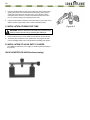
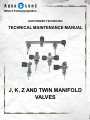
AUTHORIZED TECHNICIAN
TECHNICAL MAINTENANCE MANUAL
J, K, Z AND TWIN MANIFOLD
VALVES
J, K, Twin Manifold Valve Service Manual
Contents
COPYRIGHT NOTICE.............................................................................................................
INTRODUCTION......................................................................................................................
WARNINGS, CAUTIONS AND NOTES...................................................................................
SCHEDULED SERVICE..........................................................................................................
GENERAL PREVENTATIVE MAINTENANCE........................................................................
GENERAL GUIDELINES........................................................................................................
GENERAL CONVENTIONS....................................................................................................
3
3
3
3
3
3
4
J-VALVE AND TWIN MANIFOLD VALVE:
DISASSEMBLY PROCEDURE...............................................................................................
REASSEMBLY........................................................................................................................
ATTACHING VALVE ASSEMBLY TO THE CYLINDER.........................................................
TESTING.................................................................................................................................
EXPLODED PARTS DRAWINGS...........................................................................................
4
6
8
9
10 K-VALVE AND Z VALVE:
DISASSEMBLY PROCEDURE...............................................................................................
REASSEMBLY........................................................................................................................
ATTACHING VALVE ASSEMBLY TO THE CYLINDER.........................................................
TESTING.................................................................................................................................
12
13
13
13
EXPLODED DRAWING..........................................................................................................
15
TABLE 1 - RECOMMENDED TOOL LIST..............................................................................
16
TABLE 2 - RECOMMENDED LUBRICANTS AND CLEANERS........................................... 17 TABLE 3 - TORQUE SPECIFICATIONS................................................................................
18
TABLE 4 - TEST BENCH SPECIFICATIONS........................................................................
18
19
TABLE 5 - TROUBLESHOOTING GUIDE.............................................................................
PROCEDURE A - CLEANING AND LUBRICATION.............................................................. 21
APPENDIX A - REPLACEMENT OF NYLON DIP TUBES.................................................... 22
VALVE ADAPTER ILLUSTRATION.......................................................................................23
COPYRIGHT NOTICE
Maintenance Procedures for the User
This manual is copyrighted, all rights reserved. It may not, in
whole or in part, be copied, photocopied, reproduced, translated,
or reduced to any electronic medium or machine readable form
without prior written consent from Aqua Lung America. It may
not be distributed through the internet or computer bulletin board
systems without prior written consent from Aqua Lung America.
©2007 Aqua Lung America, Inc.
J, K, Z & Twin Manifold Service Manual
1. A
fter each dive, the cylinder and valves should be rinsed with
fresh tap water. This rinsing will prevent excess build-up of
corrosive salts and verdigris.
2. After rinsing, allow the valve body to air dry. When the
exterior of the valve appears dry, release a small amount of
air through the valve by slowly turning the on/off handwheel
counterclockwise. This venting process will remove any
moisture, or dirt particles that may have entered the outlet
orifice of the body. Once the valve is vented, close the valve
by turning the handwheel clockwise.
INTRODUCTION
This manual provides factory prescribed procedures for the
correct service and repair of the Aqua Lung J-Valve, K-Valve,
Z-Valve Air and DIN Valve, and Twin Manifold Valve. It is not
intended to be used as an instructional manual for untrained
personnel. The procedures outlined within this manual are to be
performed only by personnel who have received factory authorized training through an Aqua Lung Service & Repair Seminar. If
you do not completely understand all of the procedures outlined
in this manual, contact Aqua Lung to speak directly with a
Technical Advisor before proceeding any further.
CAUTION: Never use any type of solvent to
clean any part of the valve. Be especially careful
not to expose any soft parts to silicone spray
since some aerosol propellants attack and degrade the rubber and plastic materials which are
used for seats and seals within the valve.
CAUTION: Never lubricate any part of the valve
with hydrocarbon based products, such as Vaseline®, household oil, or motor oil.
WARNINGS, CAUTIONS AND NOTES
Pay special attention to information provided in warnings, cautions and notes that are accompanied by one of these symbols:
WARNINGS indicate a procedure or situation
that may result in serious injury or death if
instructions are not followed correctly.
CAUTIONS indicate any situation or technique
that will result in potential damage to the product, or render the product unsafe if instructions
are not followed correctly.
NOTES are used to emphasize important
points, tips, and reminders.
SCHEDULED SERVICE
Since the personal safety of the user is dependant upon the
mechanical integrity of the valve, the complete assembly should
be serviced at a professional facility. At the minimum, a thorough
overhaul is recommended every 36 months. Equipment used
frequently and/or in polluted or chlorinated water may require
professional maintenance more frequently.
3. F
or Certified Technicians Only
Inform the user that inspection of the filter in the SCUBA
regulator might indicate that the valve and/or cylinder is
experiencing corrosion. If the filter appears discolored, the
regulator, valve, and cylinder may need a general overhaul
which will require the replacement of all soft seals and nonreusable components.
CAUTION: Since either prolonged, or improper
storage can cause internal corrosion and/or deterioration of O-ring seals, it is very important to
always reinspect the entire valve before using
after extended storage.
GENERAL GUIDELINES:
1. In order to correctly perform the procedures outlined in this manual, it is important to follow each step exactly in the or- der given. Read over the entire manual to become familiar with all procedures before attempting to disassemble the
valve, and to learn which specialty tools and replacement parts will be required. Keep the manual open beside you for reference while performing each procedure. Do not rely on memory.
2. All service and repair should be carried out in a work area specifically set up and equipped for the task. Adequate lighting, cleanliness, and easy access to all required tools are essential for an efficient repair facility.
3. NEVER SECURE THE VALVE BODY DIRECTLY IN A
VISE. Instead, install in a valve adapter (PN 280036)
attached to the work bench or back into the cylinder.
4. As the valve is disassembled, reusable components should be segregated and not allowed to intermix with nonreusable parts or parts from other units.
J, K, Twin Manifold Valve Service Manual
5.Use only genuine Aqua Lung® parts provided in the
overhaul parts kit. DO NOT attempt to substitute an Aqua
Lung® part with another manufacturer’s, regardless of any
similarity in shape or size.
REMOVAL OF VALVE ASSEMBLY FROM
CYLINDER AND DISASSEMBLY OF BODY
6.
7.
Do not attempt to reuse mandatory replacement parts under any circumstances, regardless of the amount of use the product has received since it was manufactured or last serviced.
When reassembling, it is important to follow every torque specification prescribed in this manual, using a calibrated torque wrench. Most parts are made of either marine brass or plastic, and can be permanently damaged by undue stress.
GENERAL CONVENTIONS
Unless otherwise instructed, the following terminology and
techniques are assumed:
1.
2.
3.
When instructed to remove, unscrew, or loosen a threaded part, turn the part counterclockwise.
When instructed to install, screw in, or tighten a threaded part, turn the part clockwise.
When instructed to remove an O-ring, use the pinch method
(see figure) if possible, or use a brass or plastic O-ring
removal tool. Avoid using hardened steel picks, as they may
damage the O-ring sealing surface. All O-rings that are removed are discarded and replaced with brand new O-rings.
WARNING: All air must be vented from the
SCUBA cylinder BEFORE the valve assembly
can be removed. Failure to do so will cause damage to the valve and cylinder assemblies and
could cause serious injury or death.
1. Bleed all air from the cylinder. Leave valve open, and
reserve valve down.
2a. S
ingle Valve: Using a flex handle (PN 9-44363) and a 1 3/8”
crow-foot, loosen the valve from the wrench flats at the base
of the valve. If no flats are available, tap the valve with a rubber mallet in a counterclockwise direction. Once loosened,
remove the valve by hand.
2b. Twin Manifolds: Lay the cylinder assembly on a flat bench top. Grasp the cylinder base and rotate in a counterclockwise direction. If necessary, a large strap wrench may be
used. After the first cylinder is removed, stand up the other
cylinder and tap the valve with a rubber mallet in a counterclockwise direction. Once loosened, unscrew the valve by
hand.
3. Remove the O-rings (12 and 14) from the valve body.
4. If the dip tube(s) (13) is made of plastic, replace it with
a brass tube. For complete information on how to replace a plastic tube(s), see Appendix A in this manual.
4.
Numbers in parentheses reference the key numbers on the
exploded parts schematics. For example, in the statement,
“...remove the stem (10) from the...”, the number 10 is the key number to the stem part number 052521.
DISASSEMBLY PROCEDURE
NOTE: Before performing any disassembly, refer
to the exploded parts drawing, which references
all mandatory replacement parts. These parts
should be replaced with new, and must not be
reused under any circumstances - regardless
of the age of the valve or how much use it has
received since it was last serviced.
CAUTION: Use only a plastic or brass o-ring
removal tool (PN 944022) when removing o-rings
to prevent damage to the sealing surface. Even
a small scratch across an o-ring sealing surface
could result in leakage. Once an o-ring sealing
surface has been damaged, the part must be
replaced with new. DO NOT use a dental pick or
any other steel instrument.
NOTE: Prior to removal of the safety plug (15c),
the Air Flow Control (AFC) valve or the reserve
assemblies, the valve body must be properly
secured. The preferred method is to mount the
valve body in a table mounted valve adapter
(PN 280036) or, as an alternative, to install the
valve body into an EMPTY cylinder. NEVER
place the valve body in a vise. A vise will damage the body and necessitate replacement.
5.Remove the safety plug (15c) with the 1/2-inch wrench by turning the wrench counterclockwise.
6a.Safety disc removal (recommended method): To remove the
safety disc (15a), Aqua Lung® recommends to blow it out
with an air nozzle. To do this, first remove the valve from
the cylinder or valve adapter. Close the on/off valve. While
covering the safety disc hole with a cloth or rag, insert the
end of the air nozzle into the dip tube and apply a short blast
of air to blow out the safety disc. Lift out the gasket (15b).
Discard the plug, disc and gasket. Reinstall the valve into
the table mounted valve adapter (PN 280036) or cylinder.
CAUTION: When removing the safety disc and
gasket (15a and 15b) with an O-ring tool, take
care not to damage the disc sealing surface
of the valve body with this tool. If this should
occur, the entire valve body will have to be
replaced.
6b.Safety disc removal (alternate method): With the O-ring tool,
puncture the center of the disc (15a) and remove it, then,
using the same tool, lift out the gasket (15b). Discard the
plug, disc, and gasket.
7.If you are disassembling a manifold, use a 3/4-inch wrench
or deep socket to unscrew the plug (24). Lift off the gasket
(25). Discard the gasket.
8.Remove the valve handle retainer (1) from the assembly
with the modified screwdriver. Then remove the spring (2),
handwheel (3), and washer (4).
CAUTION: If the bonnet (5) has notches on the
corners of the wrench flats (see Figure 1), it is a
left hand thread. Special care must be taken when
removing or replacing this bonnet. Turn clockwise
to loosen and counterclockwise to tighten.
Disassembly or Reserve Mechanism
J-Valve and Twin Manifold only
13.Place the valve in an adapter (PN 280036) or an EMPTY
cylinder. Unscrew the valve-handle retainer (1) with the
modified screwdriver. Then remove the spring (2), lever (23)
and washer (4).
CAUTION: The reserve valve bonnet (22) has standard, right-handed threads.
14.Using a 5/8-inch wrench, remove the bonnet (22). Remove
o-ring (20) and back-up ring (21). Discard o-ring and backup ring.
15.Next, remove the stem (18), small O-ring (8), gasket (19).
Discard the O-ring and gasket. Remove the valve body from
the adapter (PN 280036) or cylinder.
NOTE: A light tap on the reserve mechanism or
rotation of the reserve cam mechanism with a
flat-bladed screwdriver may be helpful in removing the reserve assembly (16) from the valve
body.
16.Tilt the valve body downward until washer (17) and reserve
assembly (16) fall out of the body.
Figure 1
9.Remove the bonnet (5) by unscrewing it CLOCKWISE with
a 3/4-inch wrench. Then remove the external O-ring (6) and
discard.
10.Next remove the stem (10). With a blunt, non-metallic or
brass instrument, remove the O-ring (7) and back-up ring (8)
from inside the bonnet. Discard the O-ring and back-up ring.
NOTE: Item 9 is a blue colored thrust washer and
must be replaced during service. If a white thrust
washer is found instead, the stem (10) must also
be replaced. Do not reuse these parts.
11.Remove and discard the blue thrust washer (9) from the
shank of the stem (10).
12. Use the medium, flat-bladed screwdriver to remove the seat assembly (11) from the valve body by turning the screw
driver counterclockwise. Discard the used seat. Now remove
the valve or manifold from the adapter or empty cylinder.
This concludes the disassembly of the K-Valve.
CAUTION: If, after inspection, replacement of the reserve assembly is called for, be sure the new assembly fits the body. On valve bodies which have “Japan”
stamped on the base, use only reserve assemblies
with part number 052548. This part will have a red dye
marking to make identification easier. Bodies without
“Japan” markings call for reserve assemblies numbered 052508. These are dyed black on the end.
WARNING: Failure to install the correct reserve
assembly could cause a malfunction, resulting
in loss of air supply to the diver.
This concludes the disassembly of the J-Valve and Twin
Manifold. Before beginning reassembly, perform all the
cleaning and lubrication procedures outlined in Procedure
A on page 21.
J, K, Twin Manifold Valve Service Manual
REASSEMBLY
1.Insert an unlubricated O-ring (12) into the valve body face.
Install the O-rings (14) onto the valve body.
WARNING: Observe the manufacturer’s procedures and safety precautions when using
cyanoacrylate adhesives.
2.If the dip tube (13) is to be replaced, place a small amount
of LocTite 680® on the tube’s threads. Then manually
screw the tube into the bottom of the body and tighten until
handtight. Allow to dry for 12 hours before assembling onto
bottles. (For more on removal and installation of dip tubes,
see Appendix A).
Figure 2
NOTE: The safety disc assembly (15) includes
three components; the plug, disc and gasket.
The complete assembly must be installed during
service.
3.First, drop the gasket (15b) into the body. Then drop in
the safety disc (15a) with color side out. Now thread the
new safety plug (15c) into the orifice. Do not lubricate the
safety plug. If reassembling a twin manifold, repeat this
procedure for the second burst disc assembly.
4. Using an in/lbs torque wrench and a 1/2 inch socket, tighten the safety disc(s) to 90 in/lbs.
5.If you are reassembling a twin manifold, place the new gasket (25) on the end plug (24). Do not lubricate the end
plug. Then screw the plug onto the manifold body. Using an in/lbs torque wrench and a 3/4 inch socket, tighten the plug
to 90 in/lbs.
REASSEMBLY OF THE AIR FLOW CONTROL
(AFC) VALVE AND HANDWHEEL
CAUTION: The seats (11) required by the Kvalve, J-valve, Z-valve and the Twin Manifold
are all different. Failure to install the correct
seat in each valve will lead to malfunction when
in use. The K-valve seat shown in Figure 2
has a solid nylon surface, whereas the J-valve
seat has a pressure relief through-hole in the
nylon surface. This through-hole relieves any
air pressure which may build up behind the
J-valve seat. This can be caused by air hitting
the sealing surface on an angle (Figure 3). Air
can travel around the seat. If the seat was not
designed with a pressure-relief through-hole, the
seat could rupture, close off or restrict air flow to
the first stage regulator. The K-valve seat does
not require an air-pressure relief through-hole
because air hits the sealing surface directly.
The part numbers for the different seats are as
follows:
J-valve seat - PN 052519
K-valve seat - PN 050109
Manifold seat - PN 280013
Figure 3
6.Lightly lubricate the threads of the seat (11) with Christo
Lube®, then screw the seat into the body with a medium,
flat-bladed screwdriver until it bottoms out. Failure to do so
may cause the valve to fail or come apart.
Primary AFC Valve Assembly Method:
7.Place the blue thrust washer (9) on the stem (10) followed
by the O-ring (8) and the new back-up ring (7). Be sure the
concave side of the back-up ring is against the O-ring, as
shown in Figure 4.
8a.
urn the bonnet (5) so the large opening is up. Place the
T
back-up ring (7) in the bonnet with the concave side up.
Ensure it is well seated and flat in the recess of the bonnet
using a blunt brass tool.
lip the new lubricated o-ring (6) over the threads of the
9a. S
bonnet.
10a. Insert the end of the assembled stem (10) into the groove
of the seat (11).
Continue to Step 11.
NOTE: Since the AFC valve bonnet has lefthanded threads, reverse movements are required
to loosen and tighten it.
11.
ighten the left hand bonnet (5) counterclockwise into the T
valve body by hand. Using a in/lbs torque wrench and a 3/4 inch socket, tighten the bonnet to 90 in/lbs.
NOTE: When installing the spring (2) and
retainer (1), use the handwheel (3) to fully open
the valve (turned all the way counterclockwise).
This will allow the stem to be fully extended past
the handwheel to make the installation easier.
Remove the handwheel.
12.
Figure 4
8.
M
ount the valve body on the valve adapter or an EMPTY
cylinder.
9.Install the O-ring (6) over the threads of the bonnet (5), set
this assembly aside.
10.Insert the end of the assembled stem (10) into the groove of
the seat (11).
Continue to Step 11.
Alternate Assembly Method:
7a.
P
lace the new Blue Thrust Washer (9) on the stem (10).
Place the new lubricated o-ring (8) on top of the thrust
washer. Set aside.
Figure 4a
N
ext, position washer (4) on the top of the bonnet and
place the handwheel (13) over this assembly. Set the
spring (2) into the handwheel and add the handwheel
retainer (1). Finally, use the modified screwdriver to secure
the retainer. DO NOT over tighten.
This concludes the reassembly of the air flow control valve.
J, K, Twin Manifold Valve Service Manual
RESERVE VALVE ASSEMBLY
CAUTION: If, after inspection, replacement of
the reserve assembly is called for, be sure the
new assembly fits the body. On valve bodies
which have “Japan” stamped on the base, use
only reserve assemblies with PN 052548. This
part will have a red dye marking to make identification easier. Bodies without “Japan” markings
call for reserve assemblies numbered 052508.
These are dyed black on the end.
WARNING: Failure to install the correct reserve
assembly could result in loss of air supply to the
diver and possible serious injury or death.
13.Place the washer (17) on the reserve assembly (16). Install
the reserve assembly into the body, making sure the two
alignment bosses fit into the matching grooves in the valve
body.
CAUTION: The reserve assembly (16) has two
alignment bosses that must fit into matching
grooves in the valve body. (See Figure 5).
16.Install the bonnet (22) by hand until snug. Using an in/lb
torque wrench and a 5/8” crow-foot, torque to 60 in/lbs.
CAUTION: Over-torque of the bonnet will cause
damage to the reserve assembly.
17. Position the washer (4) and reserve handwheel (23) over the bonnet. The reserve handwheel should be in the down position.
NOTE: If a new reserve mechanism is installed,
the handwheel needs to be installed in the up
position.
CAUTION: To assure that the reserve handwheel
is positioned properly on the assembly, open on/
off handwheel (3). Then pull lever down to “on”
position and blow through the dip tube (13). Air
should pass through the valve. Then try blowing
through the dip tube with the lever placed in the
“off” or up position. No air should pass through.
18.Add the spring (2) to the reserve handwheel. Using the
modified screwdriver, PN 947448, tighten the retainer (1)
into place. DO NOT overtighten.
This concludes reassembly of the reserve valve.
ATTACHING VALVE ASSEMBLY TO THE
CYLINDER
Conduct all tests after the valve is attached to the cylinder as
described below.
Figure 5
14. Install O-ring (8) onto the stem (18). Place the gasket (19)
on the shank of the stem.
NOTE: Be sure that the concave side of the
backup ring (21) faces the O-ring (20) when assembling the bonnet assembly (22).
15.Install the new back-up ring (21) and O-ring (20) on the
bonnet (22). Refer to drawing for correct placement. Set this
assembly aside. Then place the stem (18) into the groove of
the reserve mechanism assembly (16).
1.Apply a light amount of lubricant to the first five (5) threads
of the body which screw onto the cylinder.
2.Single Valves: Screw the valve into the cylinder until hand
tight. Attach a 1-3/8” crow-foot to a torque wrench. Apply the
wrench to the wrench flats and tighten the valve to 30 +/- 10
foot-pounds or tap the handwheel lightly with a rubber mallet
to approximately 30 foot-pounds.
T
win Valves: Thread one side of the twin valve into one of
the cylinders. Once hand tight, apply moderate force to the
other end of the valve to secure. Tap tight with rubber mallet.
Lay the valve-cylinder assembly on a flat bench top. Screw
the other cylinder onto the other end of the valve. Once
handtight, apply moderate force to secure the cylinder. Use
strap wrench to tighten.
NOTE: Before filling twin cylinders, attach the
backpack assembly for safety.
TESTING
After the valve is thoroughly cleaned, inspected, and reassembled, Aqua Lung® recommends that the following test be
performed by using either a test bench and/or by slowly pressurizing a cylinder. To install the valve onto a cylinder, see Attaching
Valve Assembly to Cylinder, found on the previous page.
WARNING: Pressurize the valve assembly only
up to the working pressure designated for the
valve and safety disc system. This manual has
been written for 3,000 psig valves.
LEAKAGE TEST
This test determines if there is external leakage in either the AFC
or reserve valve. To do the test, slowly pressurize the valve
assembly. When pressurizing the J-valve or Manifold reserve
valve, always make sure the reserve lever is set to the “on” or
down position.
1.Test Bench - With the AFC handwheel in the fully OPEN
position, slowly pressurize the valve in four separate stages:
first to 500 psig, then to 1,000 psig, then to 2,000 psig and
finally to 3,000 psig +/- 100 psig air pressure. At each level
of test pressure, soap test the unit and observe it for 30 seconds (see note below), or apply a soapy water solution. The
persistence of bubbles indicates leakage. If leakage does
exist, refer to the Troubleshooting Guide in Table 5. Vent
the system and completely retest, going through the entire
procedure a second time.
NOTE: It is important to retest at each pressure level
even if no leakage was found the first time through.
2.Turn the handwheel (3) to the “off” position and remove the
charging system. Soap test the unit or apply a soapy water
solution to the outlet and wait 30 seconds. If bubbles appear
from the outlet, there is leakage in and around the seat (Item
8). Vent the system and repeat this procedure to check a
second time.
INSPECT SCUBA RESERVE “J” VALVE
ACTUATION PRESSURE
1. T
ools/test equipment required: Single hose, 2-stage balanced
or unbalanced diaphragm SCUBA regulator and a SCUBA
cylinder pressure gauge (submersible or non-submersible).
PROCEDURE
NOTE: All inspecting is to be conducted under
conditions of standard temperature and pressure
(68˚-72˚F and 14.7 ambient pressure). Acceptable
reserve actuation pressure ranges: (single cylinder) minimum of 450 psig, (double cylinder) 225
psig.
NOTE: A balanced or unbalanced diaphragm
first stage regulator must be used to perform this
maintenance. Piston type first stage regulators will
not be used to perform this maintenance.
1. Place reserve handwheel in “on reserve” (down) position.
2. C
harge cylinder(s) or reduce cylinder pressure to approximately 750-800 psig.
3. Remove filler hose, if applicable.
4. Attach standard single hose, 2-stage SCUBA regulator to
valve outlet.
5. Return reserve handwheel to “start dive” (up) position.
6. Fully open cylinder valve.
radually reduce cylinder pressure using one of the following
7. G
methods:
a. Using
second stage regulator, “breathe” system down until
there is a noticeable “restriction” or increase in inhalation
resistance, or
b. F
ully depress purge button second stage as follows: 5
seconds “on”, 2 seconds “off”, to be repeated until there is
a noticeable reduction in purge airflow rate. Immediately
release purge button when restriction becomes apparent.
8. Rotate reserve handwheel to “on reserve” (down) position.
9. If regulator is equipped with submersible pressure gauge
(SPG) read remaining cylinder pressure directly. This reading
will correspond with actual reserve actuation pressure.
10. If regulator is not equipped with SPG, close cylinder valve,
bleed down and remove regulator, and read remaining cylinder pressure with separate tank pressure gauge. This reading will correspond with actual reserve actuation pressure.
10
J, K, Twin Manifold Valve Service Manual
NOTE: K-valve no
longer available;
replaced by Z-valve,
PN 054295.
NOTE: Reserve Assembly (PN 052548) is to be used on valves which
have “Japan” stamped on the base of the valve body. If replacement of the
reserve assembly is required, do not use the 052508 reserve assembly in
valves stamped with “Japan”. The 052548 reserve assembly is dyed red to
differentiate between the reserve assemblies.
Key # Part #
Description
Key # Part #
Description
J-Valve (3000 psi)
K-Valve (3000 psi), replaced by PN 054295
Nut, Handle Retaining (2 req. on J-Valve)
Spring (2 req. on J-Valve)
Handwheel
Washer (2 req. on J-Valve)
Bonnet, Left Handed Thread
Bonnet, Right Handed Thread
O-ring
Back-up ring
O-ring
Thrust Washer
Stem, K-Valve
Seat, J-Valve
Seat, K-Valve
O-ring
Dip Tube
O-ring
Safety Disc Assembly, 3000 psi
Safety Disc Assembly, 2250 psi
Reserve Assembly
Reserve Assembly, Red (See NOTE)
Washer
Stem, J-Valve
Gasket
O-ring
Back-up Ring
Bonnet
Handwheel, Reserve
Reserve Pull Rod, J-Valve
------- 054500
------- NLA
1------ 052518
2------ 050107
3------ 052541
4------ 845058
5------ 050233
------- 050216
6------ 957007
7------ 828510
8------ 820010
9------ 921019
10----- 052521
11----- 052519
------- 050109
Part numbers in BOLD ITALICS indicate standard overhaul replacement part.
12----- 820120
13----- 051821
14----- 820214
15----- 050241
------- 050242
16----- 052508
------- 052548
17----- 845021
18----- 052514
19----- 821014
20----- 820015
21----- 828515
22----- 214204
23----- 052540
n/s----- 074305
11
TWIN TANK MANIFOLD WITH RESERVE
Key # Part #
Description
Key # Part #
Description
Twin Manifold, 3000 psi, J-valve
Twin Manifold, 3000 psi, J-valve - Canada
Nut, Handle Retaining
Spring
Handwheel
Washer
Bonnet
O-ring
Back-up Ring
O-ring
Thrust Washer
Stem, K-Valve
Seat, Std. Twin
O-ring
Dip Tube
O-ring
Safety Disc Assembly, 3000 psi
Safety Disc Assembly, 2250 psi
Reserve Assembly
Washer
Stem, J-Valve
Gasket
O-ring
Back-up Ring
Bonnet
Handwheel, Reserve
Plug
Gasket
Reserve Pull Rod
------- 280000
------- 280020
1------ 052518
2------ 050107
3------ 052541
4------ 845058
5------ 050233
6------ 957007
7------ 828510
8------ 820010
9------ 921019
10----- 052521
11----- 280013
12----- 820120
13----- 051821
Part numbers in BOLD ITALICS indicate standard overhaul replacement part.
14----- 820214
15----- 050241
------- 050242
16----- 052508
17----- 845021
18----- 052514
19----- 821014
20----- 820015
21----- 828515
22----- 052515
23----- 280040
24----- 050221
25----- 821011
n/s----- 074305
12
J, K, Twin Manifold Valve Service Manual
K-VALVE • DIN VALVE • Z VALVE
AUTHORIZED DISASSEMBLY
Disassembly of this valve should be performed in an area set up
and equipped for the task. Adequate lighting, cleanliness, and
easy access to parts and tools are essential for an efficient repair
facility. Be sure to keep reusable parts separate from those to be
discarded and do not allow parts from different valves to become
intermixed.
You will need the following tools to perform the procedures
described:
a.
b.
c.
d.
Rubber mallet
3/8-inch socket wrench (PN 9-43001)
O-ring tool (PN 9440-22)
V
alve Handle Retaining Tool (PN 053035) or
modified screwdriver (PN 947448)
e. 11/16-inch wrench (PN 9-44388)
f. Foot-pound torque wrench with:
1. 11/16-inch socket, or crow foot
g. Inch-pound torque wrench with:
1. 3/8-inch socket
h. Flex handle (PN 9-44363)
i. Valve adapter (PN 280036 - Optional)
WARNING: Before removing the valve from the
cylinder, vent all air out of the cylinder. Failure to
vent all the air will cause damage to the valve,
cylinder and, what is more important, cause
serious injury or death.
1. Slowly vent all air from the cylinder. Venting air out of the
cylinder too fast causes moisture condensation that leads to
undesireable oxidation (rust, or aluminum oxide.)
2. Remove the valve assembly from the cylinder by tapping it
gently with a rubber mallet and unscrewing it counterclockwise. Set the cylinder aside.
3. a. Using an O-ring removal tool (PN 944022), remove and
discard the valve outlet O-ring (item 12).
b
. Remove and discard the valve body O-ring (14).
CAUTION: To remove the safety plug (item
15a), secure the valve by placing it into a table
mounted valve adapter, or screwing it back into
the cylinder. NEVER secure the valve in a vise.
A vise will damage the valve body and require
replacement.
4. U
sing a 3/8-inch socket wrench, turn the safety plug (15)
counterclockwise and remove it. Discard the safety plug.
5. T
urn the on-off handwheel (3) counterclockwise until the valve
is completely open. This will assist in removing the seat assembly (9) later in the disassembly procedure.
6. a
. Using the Valve Handle Retaining Tool (PN 053035) or
modified screwdriver (PN 947448), remove the lock nut (1)
by turning it counterclockwise.
b
. Remove the spring (2).
c. Remove the handwheel (3).
d. Remove the washer (4).
CAUTION: To remove the bonnet (5), secure the
valve into a table mounted valve adapter (PN
280036), or screw it back into the cylinder. NEVER
secure the valve in a vise. A vise will damage the
valve body and require replacement.
7. a
. Using an 11/16-inch wrench, remove the bonnet (5) by
turning the bonnet counterclockwise. NOTE: The bonnet
is torqued to 35-40 foot-pounds and requires considerable
strength to disengage.
b
. In most cases the stem (8) will remain in the bonnet. If this
happens, gently press on the threaded end of the stem
and separate it from the bonnet (5).
c . In most cases the teflon washer (6) will remain inside
the bonnet (5). Using the O-ring extractor tool, carefully
remove the teflon washer. Discard the washer.
d. Remove the stem o-ring (7).
8. U
sing an O-ring extractor tool, carefully remove the gasket
(10) from inside the valve body. Be careful not to damage the
threads as you lift the gasket out.
9. U
sing the slotted end of the stem, remove the seat assembly
(9) by turning it counterclockwise. Discard the seat assembly.
Remove the valve body (11) from the adapter, or cylinder.
This concludes the diassembly of the 054295 Z Valve.
For parts cleaning, please refer to Procedure A,
Cleaning and Lubrication.
13
LUBRICATION
CAUTION: NEVER lubricate any part of a valve
with hydrocarbon based products such as Vaseline®, motor oil, or silicone.
1. L
ightly lubricate all new O-rings with Christo Lube® MCG111.
AUTHORIZED REASSEMBLY
1. W
ith the valve in a valve adapter (PN 280036) or screwed
into a cylinder to hold it, thread the burst plug (15a) clockwise
into the valve until finger tight. DO NOT lubricate. Attach a
3/8-inch socket to a torque wrench and tighten the plug to 90
+/- 10 inch-pounds.
2. U
sing the slotted end of the stem (8) or screwdriver, thread
the seat assembly (9) clockwise into the valve until finger
tight. *Failure to seat the seat assembly all the way will cause
damage to the bonnet.
3. Insert a new brass gasket (10) into the valve with the round
side of the gasket facing down.
4. a. Place a new O-ring (7) onto the stem (8).
b. Place a new teflon washer (6) onto the stem (8).
5. a. P
osition the slotted end of the stem onto the seat
assembly.
b
. Slide the bonnet (5) over the stem and thread into the
valve body by turning the bonnet clockwise. Tighten the
bonnet until hand tight.
6. P
ut the valve body into a mounted valve adapter, or threaded
into a cylinder. Using an 11/16-inch crow foot, or socket attached to a torque wrench, tighten the bonnet clockwise to
35-40 foot-pounds.
7. a. Install the large teflon washer (4) over the stem.
b. Install the valve handwheel (3).
8. a. Insert the spring (2) into the handwheel.
b
. Using the valve handle tool or modified screwdriver, thread
the handwheel nut (1) clockwise onto the end of the stem.
Turn clockwise until the nut is flush with end of the stem.
9. a
. Remove from valve adapter or cylinder. Install a new Oring (14) onto the threaded end of the valve body (11).
b. Install a new valve outlet O-ring (12).
This concludes reassembly of the 054295 cylinder valve.
ATTACHING VALVE ASSEMBLY TO THE
CYLINDER
Attach the valve to the cylinder as described below:
1. A
pply a small amount of Christo-Lube® MCG 111 to the first
five (5) threads of the body (11) which screw into the cylinder.
2. T
hread the valve clockwise into the cylinder until hand tight.
Using a torque wrench, tighten the valve to 30 +/- footpounds, or use a rubber mallet and lightly tap to about 30
foot-lbs.
3. F
ill the cylinder to 100 psig and check for leaks. If no leaks
are detected, fill the cylinder to its rated capacity.
This concludes the overhaul of the 054295 Z Valve.
TESTING
After the valve is thoroughly cleaned, inspected and reassembled, Aqua Lung® recommends that the following test be
performed by using either a test bench and/or by slowly pressurizing a cylinder. To install the valve into a cylinder, see “Reinstalling the Valve into the Cylinder,” on this page.
WARNING: Pressurize the valve assembly only
up to the working pressure designated for the
valve and safety disc system. This manual has
been written for up to 3500 psig valves.
Leakage Test
NOTE: If tests are run on a flow test bench, it will
be impossible to submerge the valve in water.
To test for leaks use a soapy water solution in a
spray bottle.
1. T
est Bench - Slowly pressurize the valve assembly. With the
on/off handwheel (3) in the full open position, cap the valve
outlet using a regulator and slowly pressurize the valve in
four separate stages: first to 500 psig, then to 1000 psig,
then to 2000 psig, and finally to 3000 or 3500 psig. At each
level of test pressure, soap test the unit and observe it for 30
seconds. If continuous bubblng is detected, there is a leak.
Refer to the Troubleshooting Guide in Table 5 for solutions to
this problem. Vent the system and completely retest, going
through the entire procedure a second time.
NOTE: It is important to retest at each pressure
level even if no leakage was found the first time
through.
J, K, Twin Manifold Valve Service Manual
2. T
urn the handwheel to the “off” position, but do NOT cap the
valve outlet. Pressurize the inlet to 3000 or 3500 +/- 100 psig
air pressure. Soap test the unit for 30 seconds. If bubbles
appear from the outlet, there is a leak in and around the seat
(9). Vent the system and repeat this procedure to check a
second time.
LEAKAGE TEST
This test determines if there is external leakage in either the AFC
or reserve valve. To do the test, slowly pressurize the valve
assembly. When pressurizing the J-valve or Manifold reserve
valve, always make sure the reserve lever is set to the “on” or
down position.
1.With the AFC handwheel in the fully OPEN position, slowly
pressurize the valve in four separate stages: first to 500
psig, then to 1,000 psig, then to 2,000 psig and finally to
3,000 psig +/- 100 psig air pressure. At each level of test
pressure, soap test the unit and observe it for 30 seconds
(see note below), or apply a soapy water solution. The
persistence of bubbles indicates leakage. If leakage does
exist, refer to the Troubleshooting Guide in Table 5. Vent
the system and completely retest, going through the entire
procedure a second time.
NOTE: It is important to retest at each pressure level
even if no leakage was found the first time through.
2.Turn the handwheel (3) to the “off” position and remove the
charging system. Soap test the unit or apply a soapy water
solution to the outlet and wait 30 seconds. If bubbles appear
from the outlet, there is leakage in and around the seat (8).
Vent the system and repeat this procedure to check a second time.
Valve Inlet-Flow Test
The purpose of this test is to verify a measured, controlled flow
of air through the valve inlet.
Begin the test by applying 100 +/- 10 psig to the valve inlet. The
flow from the valve outlet should be 300 SCFM minimum.
This concludes the testing for the Z-valve.
14
15
K-VALVE • DIN VALVE • Z-VALVE AIR • Z-VALVE EAN (Discontinued)*
*NOTE: The EAN Z-Valve that was
sold with a green handwheel by U.S.
Divers, 1997-1999, is still supported
with an overhaul parts kit, part
number 900209. All other parts are
no longer available. The EAN
Z-Valve uses parts that are not
shown in the schematic on this page.
Key # Part #
Description
Key # Part #
Description
Z-Valve - 3,000 psi (Air)
Service Kit, K- or Z-Valve, 3000 psi Only
Locknut, Handwheel
Spring, Handwheel
Handwheel
Washer, Handwheel
Bonnet
Washer, Packing
O-ring, Stem
Stem
Seat Assembly
Gasket, Bonnet
Body, K-Valve
Body, DIN Valve
Body, Z-Valve
O-ring, Outlet
Dip Tube
O-ring, K-Valve
O-ring, DIN Valve
Safety Plug Kit, 3,000 psi (Aluminum)
Safety Plug Kit, 3,500 psi (HP Steel)
Safety Plug Kit, 2,400 psi (LP Steel)
Safety Plug Kit, 2,250 psi (LP Steel)
Dust Cap, K-Valve
Dust Cap, Z-Valve
------- 054295
------- 5240-KIT
1------ 054207
2------ 054209
3------ 52406A
4------ 054212
5------ 054204
6------ 054205
7------ 820010
8------ 054208
9------ 054203
10----- 054216
11a---- N/A
11b---- N/A
11c---- N/A
12----- 820014
13----- 054215
14a---- 820214
14b---- 054114
15----- 054201
------- 054261
------- 054221
------- 054211
n/s----- 42485
n/s----- 054228
16
J, K, Twin Manifold Valve Service Manual
Table 1
Recommended Tools List
J and Twin Manifold Valve:
PART NO. DESCRIPTION
APPLICATION
9-44363
944022
N/A
N/A
N/A
N/A
N/A
Bonnets, plugs
Removal of O-rings
Dip tube (13)
Dip tube (13)
Bonnet nuts, safety plugs
Safety Disc Assembly (15) [Used with torque wrench]
Bonnet (5) [Used with torque wrench]
9-43226
Flex handle
O-ring tool (brass)
Sears No. 4 EZ out
5/16-18 Thread tap
Torque wrench, inch-pound
1/2” socket
5/8” crow foot and open end
wrench
3/4” socket
N/A
1 3/8” crows-foot
9-47448
Medium blade screwdriver
Shop wrenches (assorted)
Rubber mallet
Valve Adapter
280036
Bonnet (5); Manifold plug (Item M1) [Used with torque
wrench]
(Optional) Valve removal / installation
Seat (11); Valve Handwheel Retainers (1)
(Optional) Valve removal
Holding valve during disassembly and reassembly
K and Z Valve:
PART NO. DESCRIPTION
APPLICATION
0530-35
9-44388
9-44022
Valve Handle Retaining Tool
11/16-in wrench
O-ring tool kit
Foot-pound torque wrench
3/8-in socket
(used with ft-lb torque wrench)
11/16-in crow foot, or socket
(used with ft-lb torque wrench)
Removal of valve handwheel (item 9)
Removal of valve bonnet (item 5)
Removal of valve O-rings
Tightening parts on reassembly
Tightening burst plug (item 15)
Inch-pound torque wrench
Tightening parts on reassembly
Valve adapter
Holding valve during disassembly and reassembly
9-43001
9-43625
280036
Tightening bonnet (item 5)
17
Table 2
Recommended Lubricants & Cleaners
Lubricant/Cleaner
Application
Source(s)
Christo-Lube® MCG-111
(pure silicone grease)
All O-rings, threaded metal
parts
Aqua Lung, PN 820467 (16.0 oz)
or 820466 (2.0 oz)
Lubrication Technologies
7595 Gallia Pike
Franklin Furnace, OH 45629
(800) 477-8704
CAUTION: Silicone rubber requires no lubrication or preservative treatment. DO NOT apply grease or
spray to silicone rubber parts. Doing so may cause a chemical breakdown and premature deterioration
of the material.
Ultrasonic cleaning tank with
ultrasonic detergent
Metal, reusable plastic and
rubber parts.
Various. List of suppliers available
from Aqua Lung.
NOTE: Use of an ultrasonic cleaning tank with an ultrasonic detergent is the preferred and
recommended method of cleaning metal parts.
Oakite #31
Brass and stainless steel
parts
Chemetall Oakite Products, Inc.
50 Valley Road
Berkeley Heights, NJ 07922
White distilled vinegar (100 gr.)
Brass and stainless steel
parts
“Household” grade
NOTE: Both Oakite #31 and distilled vinegar are suitable for cleaning, especially heavy corrosion,
verdigris, and mineral deposits. DO NOT use muriatic acid for the cleaning of any parts. Muriatic acid,
even when strongly diluted, can harm chrome plating, and may leave a residue that is harmful to O-ring
seals and other parts.
Liquid dishwashing detergent
(diluted with warm water)
All reusable parts
“Household” grade
Snoop™
Leak testing
Nupro Company
4800 E 345th Street
Willoughby, OH 44094
(440) 473-1050
18
J, K, Twin Manifold Valve Service Manual
Table 3
Torque Specifications
J and Twin Manifold Valve:
PART NO.
DESCRIPTION (KEY NUMBER)
TORQUE
050241 or
050242
050233
052515
050221
280000 or
280020
Safety plug (15)
90 inch-pounds
AFC Bonnet (5)
Reserve Bonnet (22)
Plug (Item M1)
Twin Manifold
90 inch-pounds
60 inch-pounds
90 inch-pounds
approximately 30 +/- 10 foot-pounds,
tap with rubber mallet / strap wrench
PART NO.
DESCRIPTION (KEY NUMBER)
TORQUE
0542-04
Bonnet (5)
35-40 foot pounds
0541-16
0542-18
Burst Plug (15)
Body (11a/b/c)
90 +/- 10 inch pounds
30 +/- 10 foot pounds (approximately)
K and Z Valve
Table 4
Test Bench Specifications
J and Twin Manifold Valve:
TEST
CONDITION
ACCEPTABLE RANGE
Leak Test
Reserve Mechanism
Single Cylinder
Reserve Mechanism
Double Cylinder
3,000 (+/- 100) psig
750-800 psig maximum
No leaks allowed
450 psig (single cylinder) minimum
750-800 psig maximum
250 psig minimum
Test
Condition
Acceptable Range
Leak Test
3000 +/- 100 psig inlet
pressure
100 +/- 10 psig inlet pressure
No leaks allowed
K and Z Valve
Valve Inlet Flow Test
300 SCFM minimum
19
Table 5
Troubleshooting Guide
J and Twin Manifold Valve:
SYMPTOM
POSSIBLE CAUSE
TREATMENT
Air leakage from on-off
handwheel
1. Trapped air.
Remove handwheel and recheck
in water.
2. Check torque specs on bonnet. (5)
Tighten bonnet to 90 inch-pounds
+/- 3 inch-pounds.
3. Torque or O-ring on bonnet.
Remove bonnet and check O-ring.
Replace O-ring if necessary. Reinstall and torque to 90 inch-pounds.
4. Stem leak.
Remove bonnet and check for
missing parts. Replace O-ring
and/or backup ring if necessary.
Reassemble and torque to 90 inchpounds.
1. Check torque specs on bonnet. (5)
Tighten bonnet to 60 inch-pounds
+/- 3 inch-pounds.
2. O-ring or backup ring on bonnet.
Remove bonnet and check O-ring.
Replace O-ring if necessary. Reinstall and torque to 60 inch-pounds.
3. Stem leak.
Remove bonnet and check for
missing parts. Replace O-ring if
necessary. Reassemble and torque
to 60 inch-pounds.
Air leakage from valve
outlet (valve closed)
1. Check seat assembly (11) or seating orifice machined
in valve body.
eplace any damaged parts, clean
R
any parts that may be dirty or corroded.
Air leakage from safety
plug/disc assembly
1. Check torque of safety plug (15). NOTE: Must be done Tighten safety plug to 90 +/- 10
when valve is NOT pressurized.
inch pounds.
Air leakage from reserve
lever
Not holding back air while
reserve is in “up” position
No flow or restricted flow
of air when reserve is in
“down” position (valve
handwheel open)
2. Examine gasket (19), disc (15a), plug seating surface
(15) and gasket seating surface in valve body.
Replace damaged parts, clean any
parts that may be dirty or corroded.
1. Examine seating surface in valve body (1) on reserve
side.
Replace or clean valve body.
2. Examine seat swedged to reserve mechanism. (16)
Replace reserve mechanism.
3. Spring tension in reserve mechanism. (16)
Replace reserve mechanism.
4. Incorrect reserve mechanism. (16)
Install proper reserve mechanism.
1. Check reserve mechanism (16) for damaged or worn
parts.
Replace reserve mechanism.
2. Handle was installed incorrectly.
Remove and replace in correct
position.
20
J, K, Twin Manifold Valve Service Manual
K and Z Valve:
Problem
Probable Cause
Recommendation
Air leaks from
on-off handwheel
(valve closed)
• Bonnet (5) not fully tightened • Tighten bonnet to 35-40 foot-pounds
• Seat (9), O-ring (7), washer
(6) dirty, damaged or worn
• Check parts and replace if necessary
• O-ring sealing surfaces on
bonnet (6) or stem (3) damaged
• Check parts and replace if necessary
Air leaks from
• Seat (9) dirty, damaged or
• Replace seat
valve outlet (valve
worn
closed)
• Machine seating orifice in
• Clean or replace part
valve body dirty, or damaged
Air leaks from
safety plug
Air leakage
between valve
and cylinder
• Safety plug (15) dirty,
damaged or worn
• Safety plug not tightened
• Machined seating orifice
dirty or damaged
• Valve not tightened in
cylinder
• O-ring (14) dirty, damaged or
worn
• O-ring sealing surfaces on
valve and cylinder dirty, or
damaged
• Replace safety plug
• Torque to 90 +/- 10 inch-pounds
• Clean or replace part
• Tighten valve to 30 +/- 10 foot pounds
• Loosen and re-tap
• Replace O-ring
• Clean, or replace parts
21
Procedure A - Cleaning and Lubrication
CAUTION: NEVER use any type of solvent to
clean any rubber or plastic part of the valve. Be
especially careful not to expose any soft parts
of the valve to silicone spray because some
aerosol propellants attack, or degrade the rubber
and plastic materials that are used for seats and
seals within the valve.
WARNING: When working with solvents and
cleaners, observe all procedures and safety precautions given by the manufacturer.
Degreasing
Reusable metal parts should be degreased with a warm, soapy
water solution (see Table 2). A soft nylon bristle brush may also
be used, taking care not to scratch the rubber or plastic parts.
Ultrasonic Cleaning
1. R
outine replacement parts need not be cleaned. Clean all
metal parts in an ultrasonic cleaning tank with a suitable
detergent.
2. If an ultrasonic cleaning tank is not available, the following
(and less preferred) method can be substituted: Remove any
dirt, or flaking material with a soft bristle brush. NEVER USE
A WIRE BRUSH. Place metal parts in a recommended acid
bath solution such as vinegar or Oakite 31 (see Table 2) and
gently agitate for three to four minutes.
CAUTION: Excessive cleaning times beyond
those recommended may damage plated parts.
Only brass, plated brass and stainless steel parts
should be immersed in an acid cleaning solution.
Do not allow a soaking period in acids or basic
solutions to exceed ten minutes.
WARNING: Air pressure must be less than 30
psig when blow drying parts. Safety glasses
must also be worn.
3. R
emove parts from the bath, rinse with clean, fresh water
and blow dry with filtered, low pressure air (30 psig).
Plastic Parts
Parts made of plastic, such as handwheels, may be soaked and
cleaned in a solution of warm water mixed with mild dish soap.
Use only a soft nylon toothbrush to scrub away any deposits.
Rinse in fresh water and thoroughly blow dry, using low pressure
filtered air.
CAUTION: Do not place plastic parts in acid solutions. Doing so may alter the physical properties of the
component, causing it to prematurely degrade and/or
break.
PARTS INSPECTION
1. S
ince all soft seal parts in the valve are to be replaced during a general overhaul, these do not require inspection. In
addition, any parts showing excessive wear should also be
replaced.
CAUTION: All components to be reused must be
given a meticulous visual check before reassembly. Use a high intensity light and magnifier for all
steps in this section.
2. V
isually inspect all new soft seals, especially O-rings for any
imperfections before you install them.
3. V
isually inspect all reusable parts for cracks, burrs, scoring
and corrosion.
4. Inspect all threaded parts for deformation, galling, crossthreading, or stripping. Replace the parts if necessary.
losely inspect all plastic parts for distortion, cracking, defor5. C
mation or solvent attack. Replace the parts if necessary.
6. A
ll O-ring sealing surfaces must be completely smooth and
free of nicks, burrs, scoring, corrosion, and pitting. Replace
the parts if necessary.
Lubrication and Dressing
All O-rings should be lubricated with Christo-Lube® MCG-111.
Dress the O-rings with a very light film of grease, and remove
any visible excess by running the O-ring between the thumb
and the forefinger. Avoid applying excessive amounts of ChristoLube® grease, as this will attract particulate matter that may
cause damage to the O-ring.
*Soapy water is defined as “household” grade liquid dishwashing
detergent diluted in warm water.
22
J, K, Twin Manifold Valve Service Manual
Appendix A: Replacement of Nylon Dip Tubes
- Aqua Lung J, K and Twin Manifold Valves
All nylon dip tubes (PN 052532) are to be replaced with brass dip tubes (PN
051821). The replacement of the nylon tubes, which may be found on older
Aqua Lung® valve assemblies 054500 and 054000, must be done on or before
the twelve (12) month visual inspection requirement for valves. The procedure
for removal and replacement is detailed below.
A. REMOVAL OF THE VALVE FROM THE CYLINDER
Figure A-1
1.VENT OFF ALL AIR IN THE CYLINDER OR UNTIL THE CYLINDER IS
EMPTY. FAILURE TO DO SO COULD RESULT IN SERIOUS INJURY OR
DEATH.
2.Unscrew the valve counterclockwise using the procedures outlined on page
4, “Removal of Valve Assembly”. Remove the valve from the cylinder.
B. REMOVAL OF NYLON DIP TUBES
1.With a pair of pliers, unscrew the tube counterclockwise and remove it (See
Figure A-1). If the tube will not unscrew, soak the valve assembly in hot water. If soaking does not break the adhesive, use pliers to snap off the tube
flush with the base of the valve.
NOTE: If the tube unscrews and there is no evidence of nylon chips
or adhesive residue in the threads, proceed to step 3.
2.After snapping off the tube, use Sears No. 4 EZ-Out (or equivalent tool), to
loosen the threaded portion of the tube remaining in the base of the valve.
To do this, hold the valve over the EZ-Out and thread the EZ-Out up into
the valve as shown in Figure A-2. (This position will help prevent nylon
chips from the tube from dropping into the valve assembly.)
3.To remove any nylon chips or adhesive residue from the threads, screw
a 5/16-18 thread tap clockwise up into the valve base (See Figure A-3).
Repeat this step until the threads are clean.
Figure A-2
WARNING: Air pressure must be less than 30 psig when
blowing out parts. Use of safety glasses is also required.
CAUTION: To prevent particles from entering the valve mechanism, it is necessary to blow out chips of nylon as described
in Step 4. When performing this procedure, be sure to blow air
only through the outlet port. This will allow all chips of nylon to
fall only through the base of the valve, thereby not contaminating the valve assembly.
Figure A-3
23
4.Using low-pressure filter air, blow out the valve body. This is done by first
opening the cylinder valve handwheel and then blowing air through the
outlet boss of the valve body (see Figure A-4). If the dip tube is being
removed from the reserve or J-valve, ensure that the reserve lever is in
the “on” or down position prior to blowing out the valve.
5.Inspect female threads at the base of the valve body for nylon chips. If any
debris is evident, repeat steps 3 and 4 until the threads are clean.
C. INSTALLATION OF BRASS DIP TUBE
WARNING: Observe adhesive manufacturer’s procedures and
safety precautions when using cyanoacrylate adhesives.
1. Place a small amount of LocTite 680® on male threads of brass dip tube.
2.Thread the tube clockwise into the cylinder valve. Then tighten the tube
until it is handtight. Allow to dry overnight before reinstalling into cylinder.
D. INSTALLATION OF VALVE ONTO CYLINDER
F
or installation instructions, turn to page 13, “Attaching Valve Assembly to
the Cylinder”.
VALVE ADAPTER (PN 280036-sold separately)
Figure A-4
Aqua Lung® • 2340 Cousteau Court, Vista, CA 92081 • Telephone: (760) 597.5000 • Fax: (760) 597.4900 • www.aqualung.com/military