1
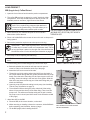
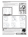
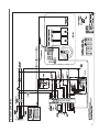
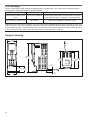
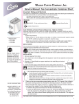
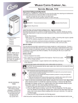
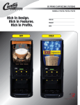
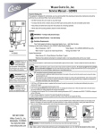
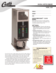
Wilbur Curtis Company, Inc.
Service Manual, Liquid Coffee Machine
Important Safeguards/Symbols
Models Included:
■ CLC
■ CLCA
This appliance is designed for commercial use. Any servicing other than cleaning and maintenance
should be performed by an authorized Wilbur Curtis Company service technician.
• Do NOT immerse the unit in water or any other liquid
• To reduce the risk of fire or electric shock, do NOT open service panels. There are no user serviceable parts inside.
• Keep hands and other items away from hot parts of unit during operation.
• Never clean with scouring powders or harsh chemicals.
Symbols
WARNINGS – To help avoid personal injury
Important Notes/Cautions – from the factory
Sanitation Requirements
Installation
CAUTION: Equipment must be
installed to comply
with applicable federal, state,
or local plumbing/electrical
codes having jurisdiction.
CAUTION: Use this
setup procedure
before attempting
to use this appliance. Failure
to follow the instructions can
result in injury or the voiding
of the warranty.
The Curtis Liquid Coffee (CLC) machine is factory pre-set and ready to go, right from the box. The
following are factory settings for the CLC:
• Tank Temperature = 190°F
• Dispensing Mode: Manual Dispense
Generally there will never be a reason to change your CLC programming
System Requirements:
• Water Source 20 – 90 PSI (Minimum Flow Rate of 1 GPM)
• Electrical: Wired at the Factory for 120VAC operation (see attached schematic)
Setup Steps
NOTE: A water filtration system must be used to maintain a trouble-free operation. (In areas
with extremely hard water, we suggest that a sedimentary and taste & odor filter be installed.)
This will prolong the life of your dispensing system and enhance the quality of the coffee
product.
NSF International requires the following water connection:
1. A quick disconnect or additional coiled tubing (at least 2x the depth of the unit) so that the machine can be moved for cleaning underneath the unit.
2. This equipment is to be installed with adequate back flow protection to comply with ap- plicable federal, state and local codes..
3. Water pipe connections and fixtures directly connected to a potable water supply shall be sized, installed and maintained in accordance with federal, state, and local codes.
1. The unit should be level (left to right and slightly tilted back), located on a solid counter top.
Connect a water line from the water filter to the brewer.
CAUTION: DO NOT
connect this unit to
hot water. Inlet valve
not rated for hot water.
ISO 9001:2008 REGISTERED
WILBUR CURTIS COMPANY
Montebello, CA 90640
For the latest information
go to www.wilburcurtis.com
2. Connect a water line from your facility to the 3/8” flare water inlet fitting of the valve, behind the machine. Water volume going to the machine should be consistent. Use tubing sized sufficiently
to provide a minimum flow rate of one gallon per minute.
3. Plug the power cord into an electrical outlet rated at 20A.
4. Switch the toggle switch on (behind the unit) that runs power to the components in the machine. The UCM display window will activate and the heating tank will start to fill.
5. Water in the heating tank will require approximately one hour to reach operating temperature
(factory setting of 190°F). When the unit reaches operating temperature, the UCM display window will read “READY TO DISPENSE”.
FOR THE LATEST SPECIFICATIONS AND INFORMATION GO TO WWW.WILBURCURTIS.COM
1
LOAD PRODUCT
BIB (bag-in-box) Coffee Extract
1. Open the front of the unit and locate the product compartment.
2. The coffee BIB products are placed on a shelf, inside the chiller
compartment. There are two BIB selections that fit into the unit.
Available products are Decaf, Light Roast or Dark Roast.
QCD: In this section, you will see references to the
QCD. This is a plastic bag connector that attaches to
one end of the product tubing. The QCD allows you to
quickly tap a BIB product without spills or leaks.
3. Reach inside the CLC machine and pull out one of the two
tubes with a QCD at the end.
THE QCD CONNECTOR MAY BE A SNAP-IN TYPE
(HOOKING ONTO SPOUT RIM) OR IT MAY BE A
THREAD-ON QCD.
4. Place a full coffee BIB on the counter in front of the unit so the spout is
facing upward.
5. Remove the protective cap that covers the spout on the bag.
IMPORTANT – When replacing BIB product, determine the type
of coffee and it’s location on the cold compartment shelf. The Decaf or Light Roast is placed on the right side of the shelf and the
Dark Roast coffee is on the left side (see illustration on page 3).
WATER
FITTING
6. Initial setup or when replacing the BIB tubing: NOTE: Disconnect the QCD from the BIB before opening the pump
head.
To insert tubing into the water fitting/pump, follow these steps:
INSERT TUBE INTO WATER FITTING
a. Determine whether the connector will snap over the spout or screw-in. Refer to the illustration at the top of the page.
b. Attach the QCD onto one end of the tube.
c. Thread the end of the tubing (without the QCD) from the inside of
the cooled cabinet through the floor gasket (located under the pump
head). Press the end of the tubing into the open top port on the water fitting. Center the tubing in the rear hole of the gasket. Slide the
tube all the way down into the top port of the water fitting with your
thumb and forefinger.
d. Open the pump and place the tubing into the pump (see Installing
Tube in Pump, illustrations on page 3).
e. To avoid leaks: Before closing the pump, take hold of the tubing
where it is pressed into the top of the water fitting. Then close the
pump cover. This will ensure that the tubing will not pull out when
the pump cover is closed (see HOLD arrow in the illustration middle
of this page).
7. Attach the QCD to the BIB.
a. Place the BIB, in the correct location, on the shelf.
b. When removing or installing a thread-on connector, tilt the BIB back
before attaching (see illustration, bottom of page).
c. Tilt the BIB upright, after installing the QCD.
2
TO REMOVE A THREAD-ON CONNECTOR, TILT
BACK THE BIB SO IT IS FACING UPWARD
BEFORE UNSCREWING..
LOAD PRODUCT, CONTINUED
7. Route tubing correctly:
a. The Decaf or Light Roast tube will be routed through the middle of the
pump rollers, being careful not to pinch the tube. Run the tubes through
the pump rollers and to the water connector underneath.
b. For Dark Roast coffee, repeat steps a and b but the tube will be routed
through the right pump.
DARK
ROAST
DECAF
8. Close the front door to return the unit to operation.
CORRECT HOSE ROUTING
INSTALLING TUBE IN PUMP
PUMP CLOSED
PLACE TUBE ON ROLLERS
OPEN COVER
LOCK COVER
UNLOCK ROLLERS
PUMP READY
DELIVERY TUBES
IMPORTANT – Avoid sharp bends or kinks in the tubing as it enters and exits the
pump. Allow a sufficient length of tubing to provide gradual bends when routing.
When replacing product delivery tubes, use only genuine Curtis parts. Determine
correct size before ordering. Delivery tubes come in two sizes, 3.2 mm and 4.8 mm
(4.8 mm being the most common size). Refer to the parts list on page 9, items 49 and 50.
The ID tag on the peristaltic pump shows the tube size.
For peristaltic accuracy, the tube length, break-in period and product temperature are important factors. These delivery tubes have a
break-in period of 100 cycles before delivery volume is normalized.
Peristaltic tubing should be replaced every 6 months.
3
Cleaning the CLC Machine
CAUTION - Do not use harsh cleaners, liquid bleach, powders or any other substance containing chlorine. THE USE OF THESE PRODUCTS WILL VOID YOUR WARRANTY.
I. DAILY OR MORE OFTEN IF NEEDED Refer to the daily cleaning instructions on the inside of the front door.
A.Make sure power is ON.
B.To catch the rinse water, place a container on the drip screen, below the dispensing spout.
C.Proceed to the Universal Control Module (UCM) on the door (see photo, right).On
the UCM locate the RINSE button.
D.Rinse the dispensing system by pushing and holding the RINSE button,at the
same time pull on the handle of one of the coffee dispensing faucets. Continue
holding RINSE for a minimum of 10 seconds (20 ounces) or until the water running
from the spout runs clear.
E.Wipe all exterior surfaces with a damp cloth, removing any spills, residue or dust
from the unit.
F. Remove the drip tray and screen and clean thoroughly. For hard to clean deposits,
use a mild, non-abrasive detergent. Rinse with water.
G.Wipe and clean the dispensing area with a mild detergent.
II. EVERY 6 MONTHS WHEN PUMP TUBING IS REPLACED
A. Clean the mixing chamber parts with warm water and a mild detergent.
1. Remove the spout adaptor. Pull forward, twist to the left and lift it to separate the spout adaptor from the mixing chamber
2. Remove the mixing chamber. Hold the
mixing chamber and turn it clockwise to
free it from the mounting plate.
3. Clean the mounting plate.
a. Twist the mounting plate clockwise and pull it from the location pillars.
IMPORTANT – Do not remove pillars to take off
mounting plate
b. Clean the surface behind the mounting plate.
III.EVERY 6 MONTHS CLEANING – BIB METHOD
Use a concentrated cleaning solution to simplify the cleaning procedure. This procedure requires a one gallon container of
a cleaning solution containing hot water and a granulated concentrated cleaner (a cleaner like Coffee Dispenser Cleaner
Corporation #12580, Urnex or equivalent) and a one gallon pail of hot water. Mix the solution according to product directions.
A.Open the front door to access the coffee concentrate BIB product.
B. Remove the quick disconnect from both coffee BIBs and place them into the pail containing the cleaning solution.
C.Place containers under the dispenser faucet to catch the cleaning solution.
D.Open each front faucet to dispense at least half of the cleaning solution.
E.Allow the cleaning solution to sit overnight in the product dispensing tubes before flushing cleaning solution.
F. Flush the system by filling a one gallon container with clean hot water (no cleaning solution). Place the connector into the
bucket with cleaning solution. Open the faucet and dispense rinse water until all the cleaning solution has been flushed
from the system.
G.Remove the connector from the flushing container. Reconnect to the BIB coffee concentrate and dispense several cups to
prime the concentrate line or until consistency of the product is correct.
4
Cleaning the CLC Machine
IV. EVERY 6 MONTHS SANITIZING – BIB METHOD
Use a BIB style cleaning solution to simplify the sanitizing procedure. A product like BevClean (http://bevclean.com) beverage line
sanitizer comes in a 3 gallon BIB that connects directly to your BIB system for line sanitizing.
A. Remove the quick disconnect from the coffee concentrate bag.
B.Place the BIB sanitizer container next to the CLC unit. Pull the spout from the sanitizer box through the marked area. Remove the travel cap from spout.
C.Snap the bag connector onto the bag spout.
D.Grasping the bag connector (as shown in Load Product, page 2, step 5), hook-up the BIB.
E.Once the sanitizing solution box is connected, open the faucet on the dispenser and run solution through the faucet until
the sanitizer (clear liquid) is detected.
DO NOT RINSE. Allow the sanitizing solution to sit in the product delivery system overnight before continuing to the line flushing steps F and G, below.
F. Remove the quick disconnect from the BIB cleaner. Unsnap the connector catch, pulling out and removing the connector
from the spout.
G.Flush the line with warm water to remove any sanitizing solution.
H.Re-connect the coffee concentrate BIB product. Open the dispensing faucet until coffee flows from the faucet.
I. Repeat this sanitizing process for both faucets.
Note: Muliti-outlet manifolds are available for sanitizing up to eight beverage lines with one BIB sanitizer. This allows you to
run cleaner or sanitizer through all systems at one time.
V. AIR FILTER – CLEAN WEEKLY
Filters containing reusable (open cell polyurethane foam) media should be cleaned or replaced every three to six months. This filter
media may be cleaned with slightly compressed air, vacuumed, and/or rinsed with clean water. If a degreaser is required, use only
a mild detergent such as dishwashing liquid. Even though this type of filter
may be cleaned, replacement is recommended every two to three years to
ensure media durability and eliminate residual dust build-up and subsequent air flow resistance.
To clean the air filter on the CLC unit:
A. Open the front door and locate the filter slot above the BIB chiller
compartment.
B. Pull out the air filter by grasping the attached tab.
C. Wash the filter in a mild detergent solution. You may use a brush
to remove any dust, hardened debris and other particles caught by
the filtering media.
D. Rinse off the filter and allow it to dry completely.
E. Return the filter into the slot from where it was removed. Make
sure the tab faces outward.
5
Operating Instructions
1. Select the cup size.
2. Select a coffee product.
3. Center the cup on the drip screen below spout associated with the chosen product.
4. Pull the handle back to dispense coffee. Release
handle when cup is 3/4 filled.
5. Coffee will continue to flow for a moment, after releasing the handle. Allow the hot coffee to completely drip from the faucet before removing your cup.
IMPORTANT: To avoid crusting in any part of
the dispensing system, run one cup of each
coffee selection every 24 hours.
Filling a Decanter
1. Select a coffee product.
2. Center the decanter on the drip screen
below selected spout.
Curtis
Ready to Dispens
3. On the control panel, press the corresponding decanter button to start dispensing.
The decanter will start to fill when the handle is
pulled.
4. If the dispensing handle is not pulled within 5
seconds of pressing the decanter button, the unit
will return to the default settings.
IMPORTANT: Peristaltic Tubes should be replaced every
6 months for product volume accuracy.
6
Programming Mode
Entering the Programing Menus
Locate the Universal Control Module (UCM), visible on the front door (see
illustrations, right). The UCM control buttons and screen allow the user to
change the factory settings that control the product output.
To enter the programming mode, press and hold RINSE for about ten [10]
seconds until display reads Program Menus (See Photo). Release button.
Scroll through menu using ◄ or ► control button. Select menu items with
the Stop/Wash button. This button serves as a select or enter control while
you are programming the CLC unit.
IMPORTANT: Your CLC is pre-programmed and should not require reprogramming. Adjustments
should only be performed by qualified personnel.
Program Menus
*
* To select correct tube ID, Refer to Delivery Tube section on page 3.
7
Illustrated Parts – CLC
3
1
12
2
13
C
4
D
5
6
7
B
1
E
11
10
8
9
14
16
17
8
Illustrated Parts – Detail Bubbles
18
19
27
28
29
20
30
21
22
23
31
B
24
25
26
32
33
34
35
C
43
44
36
45
46
37
47
48
49
50
E
15
38
40
39
41
42
D
9
Illustrated Parts List
ITEM Nº
1
2
3
4
5
6
7
8
9
10
11
12
13
14
15
16
17
18
19
20
21
22
23
24
25
PART Nº
WC-36003*
CA-1135*
WC-36017*
CA-1127
WC-37351
WC-39751
WC- 778-101
WC-58198
WC-37408*
WC-3512
CA-1136
WC-36012
WC-13433
WC-13423-102
WC-13423-101
WC- 585-101*
WC-37409*
WC- 738 *
WC-5310
WC-1055*
WC-53127
WC-66059*
WC-66011*
CA-1024-05*
CA-1006-03*
DESCRIPTION
SCREEN ASSY, SIDE
LATCH ASSEMBLY, DOOR SIDE MOUNT
FILTER, AIR 5 3/16” X 17 3/4” X .43 THK
LAMP, ASSY 30W CLC
KIT, UCM & LABEL CLC
LABEL, UCM OVERLAY
CONTROL MODULE, UCM 120VAC CLC
COVER, ALCOVE
KIT, DRIP TRAY & SCREEN CLC
LEG, 2½ – 3¼ ADJ 3/8-16 THRD
HINGE, ASSY PLASTIC CLC
SCREEN ASSY, BACK
HARNESS ASSY COMPLETE CLC DV
HARNESS ASSY CHILLER CLC
HARNESS ASSY DOOR CLC
MICROSWITCH SPST 250V 10A CLC
KIT, FAUCET HANDLE BLK, RED, ORG*
POWER MODULE (UPM) 120V CLC
TUBE, SILICONE 5/16 I.D.
POWER SUPPLY, 120VAC TO 24VDC
TUBE ASSEMBLY, HOT WATER
ADAPTOR, SPOUT WATER/COFFEE
PLATE, WHIPPER CHAMBER N0-HOLE
PILLAR, LOCATION BLACK
CHAMBER, WHIPPER PC/CK/HC
ITEM Nº
26
27
28
29
30
31
32
33
34
35
36
37
38
39
40
41
42
43
44
45
46
47
48
49
50
PART Nº
DESCRIPTION
CA-1037-3B*
WC-54308-104
WC-43079*
WC-5350
WC-37278*
WC-2627*
WC- 899*
WC-54308DV
WC-1438-101*
WC- 522 *
WC-14034*
WC-1054
WC-1057R
WC-1057L
WC-43083
WC-8657*
WC-1053
WC-1200
WC-1514
WC 102*
WC-2402P
WC- 847*
WC-8556*
WC-37367*
WC-37366*
TUBE, EXTENSION 3.0” LG BLACK
COVER, TANK
GASKET, TANK LID CLC
TUBE, 1/2 ID x 1/8W SILICONE GEN USE
KIT, LIQUID LEVEL PROBE GT
BUSHING, CONICAL .583ID X .945 OD .886L
VALVE, DISPENSE 120V 14W
TANK, ASSY LIQUID COFFEE DV 6KW 240V
SENSOR, TANK TEMPERATURE
THERMOSTAT, HI LIMIT DPST 277V 40A
SENSOR, ASSY TEMP CHILLER CLC
CHILLER, THERMOELECTRIC
MOTOR, GEAR RIGHT 120 VAC CLC
MOTOR, GEAR LEFT 120 VAC CLC
SEAL, DOOR CLC
CONNECTOR, SCHOLLE 1910L FOR 4.8MM
PUMP, 4 ROLLER 4.8 mm 25:1 – 49:1 RATIO
CORD, 14/3 SJTO 6’ BLK W/PLUG
FUSE, HOLDER ASSY W/8A FUSE CLC
SWITCH, TOGGLE SPST 125/250VAC RSTV
ELBOW, 3/8”FL x 3/8” NPT PLATED
VALVE, INLET 2 GPM 120V 10W
HEAT SINK DUAL VOLTAGE ASSEMBLY
KIT, TUBING SILICONE 4.8MM CLC
KIT, TUBING SILICONE 3.2MM CLC
* RECOMMENDED PARTS TO STOCK
10
11
Electrical Schematic
Error Message
A Service Call phone number is displayed whenever there is a malfunction. This number will be displayed during a
Heating system SENSOR ERROR or a WATER ERROR.
ERROR MESSAGE
DESCRIPTION
CAUSE
(800) 995-0417 Water Level
Error
Fill run error / Overflow
The fill solenoid has either run for more than 10 minutes
on the initial tank fill or 1.5 minutes in normal operation
(800) 995-0417 Sensor Error
Open Sensor
Break in the temperature thermistor circuit.
Whenever an error message is displayed, you will be alerted by a repeated beeping and the screen will flash the message, on and off. Once you have fixed the malfunction, the UCM will still be locked into the error message screen and
will not operate normally. To reset the UCM, press and hold the center ¤ button until the unit turns off. Press ¤ again
to turn on the UCM control panel. If error message remains, further diagnosis is required.
Rough-In Drawing
.375”
(3 .
cm)
38.875”
(98.7 cm)
3. 5”
(59.
.5”
(3.8 cm)
7”
7.875”
( 7.8 cm) (
(3 .
12
.75”
cm)
.
cm)
( .
.5”
cm)
cm)
. 5” 3. 5”
(5 .5 cm) (59.
cm)
This Page Intentionally Left Blank
13
Product Warranty Information
The Wilbur Curtis Company certifies that its products are free from defects in material and workmanship under normal use. The following limited
warranties and conditions apply:
3 Years, Parts and Labor, from Original Date of Purchase on digital control boards.
2 Years, Parts, from Original Date of Purchase on all other electrical components, fittings and tubing.
1 Year, Labor, from Original Date of Purchase on all electrical components, fittings and tubing.
Additionally, the Wilbur Curtis Company warrants its Grinding Burrs for Forty (40) months from date of purchase or 40,000 pounds of coffee,
whichever comes first. Stainless Steel components are warranted for two (2) years from date of purchase against leaking or pitting and replacement parts are warranted for ninety (90) days from date of purchase or for the remainder of the limited warranty period of the equipment in which
the component is installed.
All in-warranty service calls must have prior authorization. For Authorization, call the Technical Support Department at 1-800-995-0417. Effective
date of this policy is April 1, 2003.
Additional conditions may apply. Go to www.wilburcurtis.com to view the full product warranty information.
CONDITIONS & EXCEPTIONS
The warranty covers original equipment at time of purchase only. The Wilbur Curtis Company, Inc., assumes no responsibility for substitute replacement parts installed on Curtis equipment that have not been purchased from the
Wilbur Curtis Company, Inc. The Wilbur Curtis Company will not accept any responsibility if the following conditions are not met. The warranty
does not cover and is void under the following circumstances:
1) Improper operation of equipment: The equipment must be used for its designed and intended purpose and function.
2) Improper installation of equipment: This equipment must be installed by a professional technician and must comply with all local electrical,
mechanical and plumbing codes.
3) Improper voltage: Equipment must be installed at the voltage stated on the serial plate supplied with this equipment.
4) Improper water supply: This includes, but is not limited to, excessive or low water pressure, and inadequate or fluctuating water flow
rate.
5) Adjustments and cleaning: The resetting of safety thermostats and circuit breakers, programming and temperature adjustments are the
responsibility of the equipment owner. The owner is responsible for proper cleaning and regular maintenance of this equipment.
6) Damaged in transit: Equipment damaged in transit is the responsibility of the freight company and a claim should be made with the carrier.
7) Abuse or neglect (including failure to periodically clean or remove lime accumulations): Manufacturer is not responsible for variation
in equipment operation due to excessive lime or local water conditions. The equipment must be maintained according to the manufacturer’s
recommendations.
8) Replacement of items subject to normal use and wear: This shall include, but is not limited to, light bulbs, shear disks, “0” rings, gaskets,
silicone tube, canister assemblies, whipper chambers and plates, mixing bowls, agitation assemblies and whipper propellers.
9) Repairs and/or Replacements are subject to our decision that the workmanship or parts were faulty and the defects showed up under normal
use. All labor shall be performed during regular working hours. Overtime charges are the responsibility of the owner. Charges incurred by
delays, waiting time, or operating restrictions that hinder the service technician’s ability to perform service is the responsibility of the owner
of the equipment. This includes institutional and correctional facilities. The Wilbur Curtis Company will allow up to 100 miles, round trip, per
in-warranty service call.
RETURN MERCHANDISE AUTHORIZATION: All claims under this warranty must be submitted to the Wilbur Curtis Company Technical
Support Department prior to performing any repair work or return of this equipment to the factory. All returned equipment must be repackaged
properly in the original carton. No units will be accepted if they are damaged in transit due to improper packaging. NO UNITS OR PARTS WILL
BE ACCEPTED WITHOUT A RETURN MERCHANDISE AUTHORIZATION (RMA). RMA NUMBER MUST BE MARKED ON THE CARTON
OR SHIPPING LABEL. All in-warranty service calls must be performed by an authorized service agent. Call the Wilbur Curtis Technical Support Department to find an agent near you.
WILBUR CURTIS CO., INC.
6913 Acco St., Montebello, CA 90640-5403 USA
Phone: 800/421-6150
Fax: 323-837-2410
Technical Support Phone: 800/995-0417 (M-F 5:30A - 4:00P PST)
Web Site: www.wilburcurtis.com
14
ECN 13045 . 4/8/[email protected]
E-Mail: [email protected]
Printed in U.S.A. 4/11
F-3697 rev E