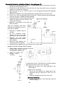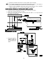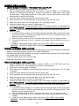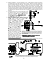
1
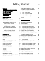
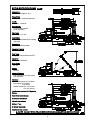
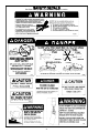
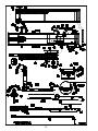
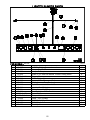
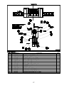
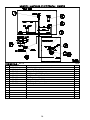
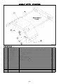
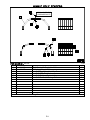
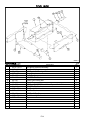
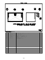
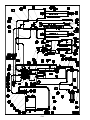
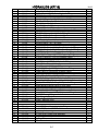
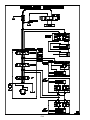
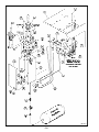
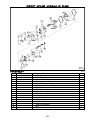
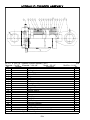
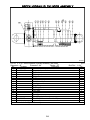
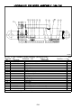
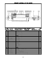
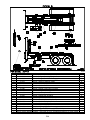
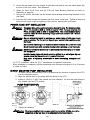
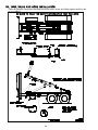
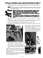
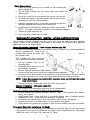
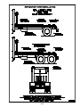
9716--1
Operation,
Installation,
and Service
Manual
KP716 HOOK HOIST
DEALER PREDELIVERY CHECK SHEET
TO BE CHECKED BY DEALER
CUSTOMER
DATE
ADDRESS
COUNTY
DEALER
ADDRESS
COUNTY
MODEL
SERIAL NUMBER
DEALER CHECK:
1.
Check that all cylinders are full of hydraulic oil and free of air. Use Mobil DTE25 or equivalent.
2.
Examine all hydraulic hoses to see that they are protected from damage.
3.
Check that all decals are in place and legible.
4.
Test the back--up and hoist--up alarms.
5.
Check that all tail lights are functioning properly.
6.
Engage the P.T.O. Check the dash light. Check for any unusual noises.
7.
Check that the control handles correspond with directional decals.
8.
Make sure all lubrication points have been lubed.
DELIVERED BY:
DATE
CUSTOMER REVIEW SHEET
1.
Owner’s manual provided.
2.
Warranty card is filled out and mailed.
3.
Review the safety warnings and cautions as listed in this manual.
4.
Review the container loading, and unloading procedures.
5.
Explain the importance of proper maintenance of the boom pivot, boom slide and hydraulic
components.
6.
Review all of the lubrication points.
DELIVERED BY:
DATE
1
Table of Contents
WARRANTY
DIRECT MOUNT HYDRAULIC PUMP
11/01
P23
DEALER PREDELIVERY CHECK SHEET
1
CUSTOMER REVIEW SHEET
1
6” x 55--1/2” Lift Cylinder
P24
TABLE OF CONTENTS
2
3” x 35” Extend Cylinder
P25
KP716 SPECIFICATIONS
3
3” x 48” Boom Extend Cylinder
P26
3--1/2” x 10” Stabilizer Cylinder
P27
3--3/4” x 10” Stabilizer Cylinder
P28
SAFETY DECALS
HYDRAULIC CYLINDER ASSEMBLIES:
4--5
OPERATING SECTION
DECALS
P29
SAFETY FIRST
O1
OPERATING INSTRUCTIONS
O1
INSTALLATION SECTION
Hook Hoist Check List
O1
SAFETY
A1
General Guidelines For Operating Hoist
O1
INSTALLATION INFORMATION
A1
Loading a container or flat rack
O1
MODEL NUMBER
A1
Dumping a container
O4
CHASSIS SPECIFICIATIONS
A1
Unloading flat racks or containers
O5
Truck Chassis Cab to Axle Formula
A2
Winch Operation (Optional Equipment)
O6
Truck Chassis Cab to Trunnion Formula
A2
Flat Rack Operation
O7
HOIST MOUNTING INSTRUCTIONS
A2
Loading a vehicle onto a flat rack
O7
POWER TAKE--OFF INSTALLATION
A3
K--PAC WARRANTY INFORMATION
O9
DIRECT MOUNT PUMP INSTALLATION
A3
OIL TANK, VALVE AND HOSE INSTALLATION
A4
HYDRAULIC TANK INSTALLATION
A5
PARTS SECTION
MAIN FRAME ASSEMBLY
P3
INSIDE CONTROL HANDLE INSTALLATION
A5
LIGHT BUMPER PARTS
P5
VALVE CONTROL INSTALLATION
A5
STABILIZER
P6
Inside Control Handle Installation
A6
WINCH
P7
Cable Connections
A6
MISCELLANEOUS ELECTRICAL PARTS
P8
ELECTRICAL SCHEMATIC
P9
SINGLE STEEL FENDERS
PNEUMATIC CONTROL INSTALLATION
A6
Pneumatic Actuator Installation
A7
P10
Pneumatic Controller Installation (In Dash)
A7
SINGLE POLY FENDERS
P11
Pneumatic Controller Installation (Tower)
A7
TANDEM STEEL FENDERS
P12
Joystick Controller & Single Valve Controller
A8
TANDEM POLY FENDERS
P13
Start--up Procedure
A8
TOOL BOX
P14
INNER BOOM HYDRAULIC INTERLOCK
TOOL BOX
P15
BUMPER INSTALLATION
HYDRAULICS
P17
HYDRAULIC SCHEMATIC
P18
WIRING HARNESS INSTALLATION
A10
GRESEN VALVE ASSEMBLY
P19
REAR STABILIZER INSTALLATION
A10
AIR CONTROLS (2 OR 3 SECTION SPOOLS)
P21
HYDRAULIC SYSTEM START--UP
A12
REMOTE VALVE & CONTROLS
P22
Lighted Bumper Installation
2
A9
A10
A10
KP716 SPECIFICATIONS
Rev.10/02
Chassis C.A.:
138”/156”(See pages A1, A2)L
Frame Width:
34”(Outside) + reinforcement thickness
G.V.W.:
33,000lbs. - 52,000 lbs.
Frame Height:
41”top of chassis unladen
(varies with chassis)
Sub Frame:
Full length 5”x 3” tube
Load Rating:
32,000 lbs. with suitable G.V.W. including
body weight
K
Dump Angle:
47_ with suitable body length
Operating Pressure:
3000 PSI
Gear Pump:
28 gpm @ 1500 rpm direct mount STD.
Operation:
In-- cab controls standard
Hook Height:
54”, 62”
Weight:
3,600 lbs.
Hydraulic Planetary:
4 ton or 6 ton 50’ of 7/16”cable w/hook,
level wind feature
Cylinders:
Twin double acting 6 x 55-- 1/2 Cylinder
Boom Cylinder 3 x 35 138CA
3 x 48 156 CA
Stabilizer Cylinder (1) 3-- 1/2 x 10 Slave
(1) 3-- 3/4 x 10 Slave
Low Pressure American S.A.E Hydraulic
System
Gear driven hydraulic pump
Braided and socked hose
Phenolic pads in boom
Sliding “L” arm
2- full sub- frame locks
K
Cantilevered lock on hook
L NOTE: DO NOT SPEC TRUCK BEFORE READING MOUNTING INSTRUCTIONS!
3
SAFETY DECALS
See Parts Listing page for part number and proper location.
4
SAFETY DECALS
See Parts Listing page for part number and proper location.
5
This page intentionally left blank.
6
P1
P2
MAIN FRAME ASSEMBLY
FOR MODELS -- 138CA, 156CA
10/02
Item
Part Number
Part Description
Qty.
Item
Part Number
Part Description
Qty.
1
2
3
4
5
6
7
8
9
10
11
12
13
14
15
16
17
18
19
20
21
22
23
24
25
26
27
28
29
30
31
62-- 351
9615-- 00-- 13
63-- 108
62-- 123
65-- 101
9274-- 415-- 3
63-- 134
64-- 154
9274-- 412-- 0
9716-- 0-- 3
9716-- 0-- 14
62-- 547
62-- 300
9716-- 240-- 0
9716-- 27-- 0
64-- 108
9716-- 241-- 0
62-- 462
63-- 107
99-- 197
9716-- 00-- 12
60-- 724
9716-- 355-- 0
64-- 146
60-- 272
23-- 707
82-- 242
64-- 162
9716-- 354-- 0
9716-- 362-- 0
62-- 764
7
4
8
4
4
4
4
4
4
2
2
2
2
1
1
9
1
8
8
2
1
1
1
2
1
2
1
1
1
1
4
32
33
34
9610-- 120-- 5A
9610-- 00-- 10
9610-- 00-- 14
1/2NC x 4-- 1/2”GD5 Cap Screw
Lift Cylinder Pin
1/2NC Nylon-- Top Lock Nut
3/8NC x 3-- 1/2”GD5 Cap Screw
1/8”STD. Zerk
Bolt Collar (Roller)
3/8NC Nylon-- Top Lock Nut
Machine Bushing
Outside Roller Assembly
Outer Boom Pivot Pin
Prop
1/2NC x 6-- 1/2”GD5 Cap Screw
1/2NC x 1”GD5 Cap Screw
Hold Down Weldment, Right
Main Pivot Shaft Weldment
1/2”STD. Flat Washer
Hold Down Weldment, Left
1/2NC x 3-- 1/4”GD5 Cap Screw
1/2NC Lock Nut
Retainer Ring 1-- 1/4”
Rod Pin, Extension Cylinder
1/8”DIA. x 1-- 1/4”Cotter Pin
Hook Lock Weldment
5/8”SAE Flat Washer
5/8”DIA. x 3-- 1/2”Clevis Pin
Hydraulic Cylinder 6”x 56”
Shock Pad
1/2”SAE Flat Washer
KP716 54”Inner Boom (138/156)
KP716 62”Inner Boom (138/156)
3/8NC x 3/4” Flat Head
Countersunk Allen Screw
Inner Boom Pad (Large)
Shim
Shim
35
36
37
38
39
40
41
42
43
44
45
46
47
48
49
50
51
52
53
54
55
56
57
58
59
60
61
62
63
64
65
66
67
68
65-- 113
9610-- 120-- 7
99-- 201
9606-- 108-- 8
9606-- 105-- 0
9606-- 108-- 10
64-- 109
9606-- 108-- 9
64-- 199
62-- 803
64-- 103
64-- 165
9610-- 00-- 3
9610-- 00-- 4
9710-- 0-- 9
9610-- 120-- 2A
60-- 109
9716-- 438-- 0
23-- 721
23-- 722
9716-- 238-- 0
9716-- 256-- 0
9615-- 303-- 0
9716-- 301-- 0
76-- 218
9615-- 00-- 6
63-- 167
9716-- 302-- 0
9615-- 304-- 0
62-- 432
76-- 180
9716-- 638-- 0
99-- 158
5210-- 563-- 3
Zerk 1/4UNF
Cylinder Pin, Extension Cylinder
Retainer Ring 1”
Roller Shaft
Guide Roller Assembly
Special Bolt
5/8”STD. Lock Washer
Retainer Washer
3 x 2 x 10 Ga. Machine Bushing
3/8NC x 7/8”GD5 Cap Screw
3/8”STD. Lock Washer
3/8”SAE Flat Washer
Shim .06 (Pad Retainer)
Shim .12 (Pad Retainer)
Pad Retainer
Outer Boom Pad
P.T.O. Lock Pin
Outer Boom Weldment
Hydraulic Cylinder, 3”x 35”
Hydraulic Cylinder, 3”x 48”
Tilt Frame Weldment (138)
Tilt Frame Weldment (156)
Main Pin Weldment
Lock Plate Weldment, Left
Spring, 1”OD x .125”W x 3.00”L
Spring Retainer
5/16NC Nylon-- Top Lock Nut
Lock Plate Weldment, Right
Lock Pin Weldment
5/16NC x 1”GD5 Cap Screw
Spring (painted)
Main Frame Weldment
Locktite (250ml)
Coupler
6
1
2
1
2
2
2
2
6
8
8
8
2
2
2
2
2
1
1
1
1
1
1
1
1
1
2
1
2
2
2
1
2
2
2
P3
1
This page intentionally left blank.
P4
LIGHTED BUMPER PARTS
FOR MODELS -- KP716
Item
1
2
3
4
5
6
7
8
9
10
11
12
13
14
15
16
17
18
Part Number
79--237
79--234
79--233
62--425
9274--0--461
79--236
79--235
79--253
79--293
79--509
79--294
79--296
9274--0--451
9274--546--0
79--254
62--362
63--139
79--250
Part Description
4.25” Dia Rubber Grommet
Lamp -- Stop/Tail/Turn
Lamp -- Back--up
3/8NC x 3/4” GD8 Hex Washer Thread Forming Screw
Bumper Cover
2” Dia. Rubber Grommet
Lamp -- 2” Dia. Clearance (Red)
Wiring Harness, Rear Bumper
Splice Connector 14 Ga to 18 Ga
Junction Box (Option)
Wiring Harness -- 30”
Beehive Light -- 2” Dia. Sealed
Cover Plate
Bumper Weldment
Lamp -- LPL Courtesy
5/16NC x 3/4” Cap Screw
5/16NC Lock Nut
Back--Up Alarm
P5
11/01
Qty.
6
4
2
8
1
7
5
1
4
1
2
2
1
1
1
2
2
1
STABILIZER
IMPORTANT:
STABILIZER CYLINDER MUST BE RUN AND CYCLED SEVERAL TIMES TO
GET THEM IN PHASE BEFORE HOOKING TO ROLLER SHAFT. DAMAGE CAN
OCCUR TO SHAFT IF THIS IS NOT DONE.
FOR MODELS -Item
1
2
3
4
5
6
7
8
9
K
Part Number
Part Description
9716--850--0
Stabilizer Main Weldment
K
3/16” DIA. x 1--3/4” Cotter Pin
64--119
1” STD. Flat Washer
K
Clevis Pin
21--1023
3--3/4” x 10” Ret/Series Hydraulic Cylinder
9716--855--0
Stabilizer Slide Weldment
9716--0--1
Stabilizer Roller Shaft
9274--26--0A
Rear Roller Assembly
21--1022
3--1/2” x 10” Ret/Series Hydraulic Cylinder
Included in cylinder assembly see pages P27 and P28
P6
10/01
Qty.
1
2
6
2
1
2
1
1
WINCH
FOR MODELS -Item
1
2
3
4
5
6
7
8
9
10
11
12
13
14
Part Number
64--108
62--569
9716--860--2
82--295
62--805
9625--0--18
9716--860--1
62--815
64--107
63--106
9716--850--0
82--249
82--250
82--251
Part Description
1/2” STD. Flat Washer
1/2NC x 1--1/2” GD5 Cap Screw
Winch Cover Plate
Hd. Roller Fairlead for 10” Drum
M12 x 1.75 x 35 x 8.8 Cap Screw
Angle -- Winch Cover
Winch Mount / Cover
M12 x 1.75 x 25 x 8.8 Cap Screw
1/2” STD. Lock Washer
1/2NC Hex Nut
Stabilizer Main Weldment
9,000# Winch (30--282 Series)
12,000# Winch (30--286 Series)
Tensioner Wire Rope Kit 10” Drum
P7
3/03
Qty.
8
4
1
1
4
1
1
8
4
4
1
1
1
1
MISCELLANEOUS ELECTRICAL PARTS
FOR MODELS -- KP716
Item
1
2
3
4
5
6
7
8
9
Part Number
79--269
9716--0--30
79--248
62--422
63--141
79--496
79--563
79--564
79--565
Part Description
Hoist Up Light
Bracket -- Safety Switch
Remote Switch
1/4NC x 1--1/2” GD5 Cap Screw
1/4NC Hex Flange Serrated Nut
Din Plug
Solenoid Valve (40 GPM)
12V Relay 30 Amp
12V Relay Connector w/ Wire
P8
10/02
Qty.
1
1
1
3
3
1
1
1
1
ELECTRICAL SCHEMATIC
P9
SINGLE STEEL FENDERS
M9706--22
FOR MODELS -- ALL
Item
1
2
3
4
5
6
7
8
11/00
Part Number
9305--55--0A
9305--57--0A
9305--56--0
62--503
63--106
44--129
62--108
9274--0--1
63--134
Part Description
Standard Fender Weldment -- (Width = 25--1/2”)
Narrow Fender Weldment -- (Width = 22--1/4”)
Fender Support Weldment
1/2NC x 1--1/2” Set Screw
1/2NC Hex Nut
Mud Flap
3/8NC x 1” GD.5 Cap Screw
Mud Flap Backing Plate
3/8NC Self Locking Nut
P10
Qty.
1
1
2
2
2
1
4
1
4
SINGLE POLY FENDERS
DRILL HOLES FOR
CARRIAGE BOLTS.
FOR MODELS -- KP716
Item
1
2
3
4
5
6
K
1/99
Part Number
44--190
82--255
K
K
K
K
Part Description
Poly Fender Kit Single Axle 26”
Mounting Kit for 44--190
5/16NC x 1” Hex Head Cap Screw
5/16” STD. Flat Washer
5/16NC Nylon--Top Lock Nut
5/16NC x 1--1/4 Carriage Bolt
Items Included in Mounting Kit
P11
Qty.
1
1
16
23
23
7
TANDEM STEEL FENDERS
FOR MODELS -- KP716
Item
1
2
3
4
5
6
7
8
9
Part Number
9274--0--3501
9274--159--0
63--106
62--503
9274--148--0
9625--0--8
9274--162--1
9625--0--7
9274--50--6
Part Description
Gusset
Fender Weldment (102” Max)
1/2NC Hex Nut
1/2NC x 1--1/2” Square Head Cone Point Set Screw
Front Fender Tube Weldment
Front Fender Mounting Tube
End Cap w/ Hole
Rear Fender Mounting Tube
End Cap
P12
2/02
Qty.
4
2
4
4
2
2
2
2
2
TANDEM POLY FENDERS
FOR MODELS -- KP716
Item
1
2
3
4
5
7/97
Part Number
44--133
9274--115--1A
9274--115--8
9274--115--5
9274--115--6
Part Description
Dual Poly Fender
Rear Fender Mount
Center Fender Mount
Front Fender Brace -- Left
Front Fender Brace -- Right
P13
Qty.
4
2
2
1
1
TOOL BOX
M9200--3
FOR MODELS -- ALL
Item
1
2
3
4
5
6
7
8
9
10
11
12
13
14
Part Number
9274--110--0
9274--36--0
62--139
9274--35--1
53--126
64--108
63--107
75--109
62--598
64--110
9274--37--0
9274--48--0
62--401
9274--59--0A
9274--45--1
Part Description
Tool Box & Platform Assembly
Tool Box Weldment
1/2NC x 1--3/4” Carriage Bolt
Hinge Strap
Wear Sleeve
1/2” STD. Flat Washer
1/2NC Self Locking Nut
Plastic Plug
1/2NC x 1--1/2”GD5 Round Head Square Neck Bolt
5/8” STD. Flat Washer
Tool Box Lid Weldment
Tool Box Rack
1/2NC x 1” Cap Screw
Tank Mounting Weldment
Pipe
P14
3/00
Qty.
1
1
2
2
4
4
4
1
2
2
1
2
2
2
2
TOOL BOX
FOR MODELS -- KP716
Item
1
2
3
4
5
6
6/97
Part Number
9606--111--0
82--245
9606--112--0
62--708
63--110
64--110
Part Description
Left Tank Strap Weldment
Steel Tool Box
Right Tank Strap Weldment
5/8NC x 2--1/2” GD.8 Cap Screw
5/8NC Lock Nut
5/8” STD. Flat Washer
P15
Qty.
1
1
1
4
4
4
P16
Item
Part Number
1
2
3
4
5
6
7
8
9
10
11
12
13
14
15
16
17
18
19
20
21
22
23
24
25
26
27
28
29
30
31
32
33
34
35
36
37
38
39
40
41
42
43
44
45
46
47
48
49
50
51
52
53
HYDRAULICS (KP716)
Part Description
10/02
Qty.
24--363R
25--310
25--326
24--387R
25--363
23--707
23--722
23--721
24--375
25--300
25--301
25--304
21--1022
21--1023
25--2496
24--373R
79--563
25--583
25--478
25--379
25--1175
25--448
25--2495
25--342
25--2502
25--449
24--1151
25--494
25--1182
24--1150
25--1180
25--493
25--2394
25--328
24--3042
25--485
SEE PG P7
25--2419
25--170
24--609
25--531
25--2402
25--235
9244--30--0A
25--2374
25--233
1/2” x 284” (JIC) Black 2W Hose Assembly
3/4(M)JIC to 3/4(F)JIC Swivel Hydraulic Fitting
37 (M) Bulkhead Tee Hydraulic Fitting
1/2 x 56” (JIC) Black 2W Hose Assembly
1--1/16 O--Ring to 3/4JIC (M/M) Hydraulic Fitting
6” x 56--1/2” Hydraulic Cylinder
3” x 48” Hydraulic Cylinder
3” x 35” Hydraulic Cylinder
1/2” x 30” Parker 436 Hose Assembly
3/4(M) O--Ring to 3/4(M) JIC Adapter Hydraulic Fitting
O--Ring 37_ Flare 90_ Ell Hydraulic Fitting
37_ Flare Male coupler Hydraulic Fitting
3--1/2” x 10” Ret/Series Hydraulic Cylinder
3--3/4” x 10” Ret/Series Hydraulic Cylinder
Dual Counterbalance Valve
1/2” x 190” (JIC) Hydraulic Hose Assembly
Solenoid Valve -- N.C. (40 GPM)
1--1/16 O--Ring to 1--1/16JIC 90_ Hydraulic Fitting
7/8(M) O--Ring to 1--1/16(M) Straight Hydraulic Fitting
7/8(M) O--Ring to 3/4(M) JIC Adapter Hydraulic Fitting
3/4NPT(M) to 3/4 Hose Straight Hydraulic Fitting
1--1/16(M) O--Ring to 3/4NPT(F) Hydraulic Fitting
2 Spool Control Valve (Reversed w/ Free Flow Spool)
1--1/16 O--Ring to 1--1/16 JIC Hydraulic Fitting
4--Way 3--Position (Rev V20) Valve Section
1--1/16(M) to 3/4NPT(F) 90 Hydraulic Fitting
3/4 x 20” Low Pressure Hose
Hose Clamp (1--3/16” to 1--3/8”)
1--1/2NPT(M) to 3/4NPT(F) Hex Reducer Fitting
3/4” x 276” Low Pressure Hose
1/2NPT(M) to 3/4 Hose End Hydraulic Fitting
3/4(M)O--Ring to 1/2NPT(F) 90_ Hydraulic Fitting
Valve, SD4--1 (SV) -- 2BLSD--SAE
9/16(M) O--Ring to 3/4(M) JIC Hydraulic Fitting
1/2 x 80 (JIC) 90 w/Sleeve -- Mega 3000 Hose Assembly
3/4(M) JIC to 7/8(M) O--Ring 90_ Hydraulic Fitting
Winch
Power Beyond Sleeve SAE #10 (V20 Valve)
1--1/4NPT to 1/1/4 Hose 90_ Hydraulic Fitting
3/4” x 96” (JIC) w/MTL Mega 3000 Hose Assembly
1--1/16(M) JIC to 1--1/4NPT (M) Hydraulic Fitting
31 GPM Pump (615)
Sight Gauge w/Temp 5”
Hydraulic Tank Weldment
3/4NPT Magnetic Plug
Oil Strainer -- 25 GPM
75--141
25--2387
1--1/4NPT Close Nipple Hydraulic Fitting
1--1/4NPT(F) x 1--1/4NPT Ball Valve
1
1
25--487
24--1136
25--215
25--2247
25--2248
(T--Bolt Type) Hose Clamp
1--1/4ID x 96” 100R4 Hose Assembly
Filler Cap Assembly
In--Tank Filter
Filter Element
2
1
1
1
1
P17
3
11
2
9
5
2
1
1
2
8
3
2
1
1
1
2
1
2
1
4/7
3
1
1
1
1
1
1
4
1
1
1
1
1
2
2
2
1
2
1
1
1
1
1
1
1
P18
GRESEN VALVE ASSEMBLY
7/00
M9706--21
FOR MODELS -- ALL
Item
1
2
3
4
5
6
7
8
9
10
Part Number
25--2495
25--2409
25--2413
25--2508
25--2408
25--2502
25--2412
25--2411
11/00
Part Description
Gresen V20 2 Spool Valve Assembly (Reversed)
Main Relief Valve
Relief Valve Seal Kit (WH Std. Relief)
Valve Section -- 4 Way, 3 Position, Free Flow Spool (Reversed)
Valve Section Seal Kit
Valve Section -- 4 Way, 3 Position Spool (Reversed)
Outlet Cover
Hex Nut
Lock Washer
Studs
Inlet Cover
P19
Qty.
1
1
1
1
1 / Section
1
1
6
6
3
1
M9716-- 12
P20
KP716 AIR CONTROL 2 OR 3 SPOOL PARTS
FOR MODELS -- KP716
Item
1
2
3
4
5
6
7
8
9
10
11
12
13
14
15
16
17
18
19
20
21
22
23
24
25
26
27
28
29
30
31
32
33
34
K
D
10/01
Part Number
K
KD
D
K
62--394
63--167
25--2495
25--2406
82--124
9610--45--0
82--288
82--126
82--124
9274--196--0
9274--196--2
62--530
64--100
63--100
9274--196--3
9274--196--4
9274--196--1
62--342
62--115
64--104
64--103
63--102
82--157
82--199
62--485
64--158
64--170
63--151
82--166
82--163
82--168
82--167
Part Description
Hydraulic Tank -- 30 Gallon
5/16NC x 2--1/2” Cap Screw
5/16NC Nylon--Top Lock Nut
Control Valve 2 Spool (Rev. w/ Free Flow Spool) V20
Valve Section, 4--Way, 3--Position Spool
Air Line
Handle Kit, V--20 Valve
Air Activator Assembly
Compression Fitting 1/8NPT(M) -- 1/4” Tube 90_
Air Line
Air Control Tower Assembly
Tower
1/4NC x 1/2” Cap Screw
1/4” STD. Lock Washer
1/4NC Hex Nut
Cover
Cap (Used when not equipped with Item 24)
Air Control Mounting Plate
1/4NC x 3/4” Hex Washer Thread Cutting Screw
3/8NC x 1--1/2” Hex Washer Thread Cutting Screw
3/8” STD. Flat Washer
3/8” STD. Lock Washer
3/8NC Hex Nut
Joystick Controller
Pneumatic Control Valve (1 valve)
#10NC x 1/2” Cross Recess Pan Head Machine Screw
P.T.O. Indicator Light
Air Valve
#10 Flat Washer
#10 External Tooth Lock Washer
#10 Hex Nut
1/4” Tube Union Tee Compression Fitting
3/8NPT Male 1/4” Tube Straight Compression Fitting
Pressure Protection Valve
1/4NPT Hex Nipple
Used with 3--Spool Valve Assembly ONLY
This is a bulk quantity item. Specify the amount required when ordering.
P21
Qty.
1
3
3
1
1
40’
2/3
2/3
5
80’
1
1
14
14
14
1
1
1
4
4
4
4
4
1
1
4
1
1
4
4
4
1
1
1
1
REMOTE VALVE & CONTROLS
FOR MODELS -- KP716
Item
1
2
3
4
5
6
7
8
9
10
11
12
13
14
15
16
17
18
19
K
10/01
Part Number
Part Description
82--238
9274--0--1305
72--112
72--109
9610--0--17
9706--0--23
72--108
9610--108--1
25--2505
Controller
Control Mount
Cable -- 84” Long
Cable -- 252” Long
Control Cable Bulkhead Plate
3 Cable Bracket
Clevis, 3/8” Hole
Valve Handle
V--20 Valve Linkage Kit
K
Link
K
Link Plate
K
Cotter Pin
K
Pin
25--2199
Die Cast Bracket
25--2201
Screw
62--106
1/4NC x 4” GD5 Cap Screw
63--141
1/4NC Hex Flange Serrated Nut
62--115
3/8NC x 1--1/2” Hex Washer Thread Cutting Screw
62--394
5/16NC x 2--1/2” GD5 Cap Screw
63--114
5/16NC Lock Nut
62--420
1/2NC x 1--1/4” GD5 Cap Screw
63--107
1/2NC Lock Nut
Items included in V20 Valve Linkage Kit
P22
Qty.
2
2
2
2
1
1
2
2
1
1
3
1
1
2
3
3
4
3
3
2
2
DIRECT MOUNT HYDRAULIC PUMP
M9610--7
Rev.2/99
FOR MODELS -Item
1
2
3
4
5
6
7
8
9
10
11
12
13
14
15
16
2/01
Part Number
25--2402
Part Description
Gear Pump
Snap Ring
Outboard Bearing
Seal
Shaft End Cover
Check Assemblies or Plug
Ring Seals
Roller Bearings
Pocket Seals
Thrust Plates
Integral Drive Shaft and Gear Set
Gasket Seals
Gear Housing
Port End Cover
Washer
Stud or Cap Screw
Nut
P23
Qty.
1
HYDRAULIC CYLINDER ASSEMBLY
23--707 6” x 55--1/2” Hydraulic Cylinder Assembly (LIFT)
Retracted -- 74--5/8” Extended -- 130--1/8”
Stroke -- 55--1/2”
Item
1
2
3
4
5
6
7
8
9
10
11
12
13
14
15
16
17
18
19
20
21
22
D
Part Number
Part Description
Manufacturer’s Label
Full Locknut
K
Wear Ring
K
Piston Seal
Piston
K
O--Ring
Stop Tube
Rod
Barrel Assembly
K
Wear Ring
Gland
K
O--Ring
K
Backup Washer
Set Screw
Cap
K
Rod Wiper
K
Rod Seal
3/8” Bolt
Nylon Lock Nut
Rod End Assembly
25--2432
Counterbalance Valve
3/4” Port Plug
D 23--808
Seal Kit ( K Items Included in Kit)
Not Included in Cylinder Assembly
P24
4/00
Rod Dia. -- 2--3/4”
Qty.
1
1
2
1
1
1
1
1
1
1
1
1
1
2
1
1
1
1
1
1
2
3
GREEN HYDRAULIC CYLINDER ASSEMBLY
Rev.9/01
23--721 3” x 35” Green Hydraulic Cylinder Assembly (EXTEND)
Retracted -- 45”
Extended -- 80”
Stroke -- 35”
Item
1
2
3
4
5
6
7
8
9
10
11
12
13
14
15
16
Part Number
25--2433
K
K
K
K
K
K
K
D
D
23--803
Part Description
Manufacturer’s Label
Counterbalance Valve
Full Locknut
Piston
Piston Seal
O--Ring
Barrel Assembly
Rod Assembly
Head
Wear Ring
O--Ring
Back--up Washer
Lock Wire
Rod Seal
Rod Wiper
Steel Plug (not shown)
Seal Kit ( K Items Included in Kit)
Not Included in Cylinder Assembly
P25
9/01
Rod Dia. -- 1--3/4”
Qty.
1
2
1
1
1
1
1
1
1
1
1
1
1
1
1
1
HYDRAULIC CYLINDER ASSEMBLY (156 CA)
Rev.9/01
23--722 3” x 48” Hydraulic Cylinder Assembly (BOOM EXTEND)
Retracted -- 58”
Extended -- 106”
Stroke -- 48”
Item
1
2
3
4
5
6
7
8
9
10
11
12
13
14
15
Part Number
25--2433
K
K
K
K
K
K
K
D
D
23--803
Part Description
Manufacturer’s Label
Counterbalance Valve
Full Locknut
Piston
Piston Seal
O--Ring
Barrel Assembly
Rod Assembly
Head
Wear Ring
O--Ring
Back--up Washer
Rod Seal
Rod Wiper
Steel Plug (not shown)
Seal Kit ( K Items Included in Kit)
Not Included in Cylinder Assembly
P26
9/01
Rod Dia. -- 1--3/4”
Qty.
1
2
1
1
1
1
1
1
1
2
1
1
1
1
1
PRINCE HYDRAULIC CYLINDER
21--1022 3--1/2” X 10” PRINCE HYDRAULIC CYLINDER ASSEMBLY (Series)
12/00
Retracted -- 22--1/4”
Extended -- 32--1/4”
Stroke -- 10”
Rod Diameter -- 1--1/4”
Item
1
2
3
4
5
6
7
8
9
10
11
12
13
14
15
16
17
18
19
20
21
22
23
24
Part Number
21--2131
21--376
21--2121
K
K
K
K
K
K
K
K
60--703
21--404
21--443
74--113
21--2088
Part Description
Piston Rod
Tube Assembly
Tie Rod Assembly
Butt
Gland Assembly
Piston
Clevis Assembly
Lock Nut
Clevis Pin
Seal Kit Decal
Port Plug
Bearing Ring
O--Ring
O--Ring
O--Ring
Back--Up Washer
Teflon Seal
U--Cup
Wiper
Bushing
3/16” DIA. x 1--3/4” Cotter Pin
Port Plug
Series Caution Decal
Cylinder WARNING Decal
Seal Kit ( K Items Included in Kit)
P27
Qty.
1
1
4
1
1
1
1
1
2
1
1
2
1
1
2
2
1
1
1
1
4
3
1
1
PRINCE HYDRAULIC CYLINDER
21--1023 3--3/4” X 10” PRINCE HYDRAULIC CYLINDER ASSEMBLY (Series)
12/00
Retracted -- 22--1/4”
Extended -- 32--1/4”
Stroke -- 10”
Rod Diameter -- 1--3/8”
Item
1
2
3
4
5
6
7
8
9
10
11
12
13
14
15
16
17
18
19
20
21
22
23
24
Part Number
21--2126
21--260
60--703
K
K
K
K
K
K
K
K
D
21--443
21--2117
74--113
21--808
Part Description
Piston Rod
Tube Assembly
Tie Rod Assembly
Butt
Gland
Piston
Clevis Assembly
Lock Nut
Port Plug
Port Plug
Bushing
Clevis Pin
3/16” DIA. x 1--3/4” Cotter Pin
Bearing Ring
O--Ring
O--Ring
O--Ring
Back--Up Washer
Teflon Seal
U--Cup
Wiper
Series Caution Decal
Seal Kit Decal
Cylinder Warning Decal
Seal Kit ( K Items Included in Kit)
P28
Qty.
1
1
4
1
1
1
1
1
1
3
1
2
4
2
1
1
2
2
1
1
1
1
1
1
DECALS
FOR MODEL - KP716
Item
1
2
3
4
5
6
7
8
9
10
11
12
13
14
15
16
17
18
19
20
21
K
Part Number
K
K
74--598
74--596
74--593
74--579
74--276
74--481
74--476
74--286
74--485
74--490
74--475
74--288
74--302
74--387
74--484
74--477
74--297
74--478
74--486
74--600
74--601
Part Description
Decal -- Important Valve Operation
Decal -- Danger Operating Outside Controls
Decal -- Danger Lock Must Be Engaged
Decal -- 32,000 Lbs.
Decal -- Warning Hydraulic Safety
Decal -- Caution Do Not Drive PTO
Decal -- Caution Set Brake
Decal -- Winch
Decal -- Danger Power Lines (Hooklift)
Decal -- Danger Hook Height Match
Decal -- American Hook Lift
Decal -- Warning Raised Hoist
Decal -- Danger Unit Operation
Decal -- Cylinder Lock
Decal -- American Hook Lift (6” x 9”)
Decal -- Caution Safety Instructions
Decal -- Warning Uneven Ground
Decal -- Important Operation Instruction
Decal -- Warning Align Container
Reflective Tape -- Red/White (NOT SHOWN)
Reflective Tape -- White (NOT SHOWN)
Specify exact quantity needed. See page A13 for suggested locations on truck frame
P29
3/02
Qty.
2
1
3
2
2
2
1
1
1
1
2
2
3
2
1
1
1
1
1
20 Ft.
4
This page intentionally left blank.
P30
KP716 HOIST MOUNTING INSTRUCTIONS
STUDY NAMES AND LOCATIONS OF THE PARTS AND FAMILIARIZE YOURSELF WITH THE
HOOK HOIST BEFORE STARTING THE INSTALLATION. READING THE STEP--BY--STEP
INSTRUCTIONS THAT FOLLOW WILL BE HELPFUL.
SAFETY
Read all of the Safety Notations in the following instructions for your own
protection. Accidents can be prevented by recognizing the cause of an accident
before it can happen.
INSTALLATION
74--335
Select an area for installation that will be large enough to accommodate the completed unit. The
surface of the work area should be as level as possible. Use the proper hand tools to insure
proper bolt tightness. Refer to the bolt chart on the previous page for the recommended torque
values for different sizes of bolts.
If a forklift is to be used to lift the KP716 from the transport vehicle to the installation area, care
should be taken not to engage chains or hooks to areas of the Hook Hoist which may cause
damage to hydraulic hoses or any parts of the structure.
EQUIPMENT DIVISION OF
Before starting installation procedures, check the
KRAUSE CORPORATION
HUTCHINSON, KANSAS
shipping list to ensure that all parts and accessories
have been supplied. Any missing items should be
MODEL
reported to K--PAC immediately.
SERIAL
MODEL NUMBER
MANUFACTURED IN COMPLIANCE WITH ANSI Z245
STANDARD IN EFFECT AT TIME OF MANUFACTURE.
Know the model number of the KP716 being mounted.
Use this model number whenever referring to assembly or parts
listing pages. The number is stamped on a Name Plate which is located on the frame member.
CHASSIS SPECIFICATIONS
SINGLE AXLE TRUCK
TANDEM AXLE TRUCK
M9716-- 28
MODEL
A
B
C
D
KP716--138
KP716--156
183”
201”
181.5”
199.5”
161.50”
179.50”
52.75”
60.50”
SINGLE
45”
28”
E
TANDEM
49”
49”
F
41”
41”
54”boom
48”
48”
G
62”boom
42”
42”
The KP716--138 / KP716--156 Hook Hoist is designed for a 30,000--46,000 lb. G.V.W.R. chassis
with 138”/156” unobstructed behind cab--to--axle or trunnion chassis clearance. Some truck
suspensions will allow frame cut--off less than 38”. It is desirable to have the axle back as far as
possible, so a longer cab--to--axle chassis can be used. If the suspension allows shorter than 21”
then check fender clearance. This is based on a K--PAC single axle fender. Note: This
information is supplied for guidelines only and does not assure the installer of other mounting
considerations.
Dimension “A” is the minimum cab to frame cut--off dimension and should be increased if a
tarper or toolbox, etc. is to be added. Also, be aware of exhausts, etc. behind the cab, measuring
from the rearmost obstruction.
A1
Truck Chassis cab--to--axle or cab--to--trunnion Specification formula:
Determine shortest “E” dimension possible with desired suspension. Also determine extra behind
cab clearance for tarper, toolbox, or other accessories. Then use the following formula to
determine CA or CT to specify: Single Axle (CA) = A -- E + extra clearance
Tandem Axle (CT) = A -- E + extra clearance
The preceding illustrations provide dimensional guidelines for compatibility with containers, etc. If
the chassis is higher or lower than the 41” dimension shown, then the lowest hook pickup
dimension will change accordingly.
HOOK HOIST MOUNTING
INSTRUCTIONS
NOTE:RIGHT and LEFT sides can be
established by standing behind the
truck frame and looking towards the
front or the direction of travel.
The KP716 Hook Hoist is designed to
mount on a standard truck frame. If
there are unmovable obstructions on top
of the truck frame, you must add spacers
to raise the hoist frame to clear, or move
the obstructions.
1. Compare the Truck Chassis with the
Hook Hoist ordered (138CA / 156CA
Hoist). Compare the specification
dimensions to determine how far
forward on the chassis the Hoist can
be mounted. It is best to mount as
far forward as possible for optimum
weight distribution. Suspension and
fender to rear holdown are the main
considerations. See truck chassis
Cab--To--Axle or CA--to--Trunnion
specifications formulas above.
2. If chassis is longer than the above
CA’s the chassis can be cut off
shorter per difference. Cut end of
frame per illustration shown at right. Measure and mark truck frame per axle location and
type (i.e. single, tandem). Measure assembled hoist to be sure adequate room is available
behind truck cab, between bumper and tires and between fender and tires.
After
double--checking your measurements, step--cut the frame to dimension. Grind the top of each
cut to a 3/8” x 45 chamfer to clear radius on top of hoist main frame rear apron. Install hoist
mainframe and weld to truck frame as shown. The minimum would be 1” behind the rear
spring shackle.
NOTE: If bolts, pipe, pipe fittings, hydraulic fittings, hoses, etc., are substituted for the
hardware supplied with the hoist, the installer must use parts of equal quality and
service strength.
NOTE: It may be necessary to relocate air tanks, fuel tank, battery cases or any other
accessories mounted in this area.
Caution: Before cutting or drilling through the truck chassis, be sure that all
hoses, wiring and lines are moved out of the path of the drill.
3. Unpackage the KP716 Hook Hoist Main Frame and prepare to lift it onto the truck chassis.
4. With the Truck Chassis prepared as previously illustrated, safely attach chains and lift the
hoist with a heavy duty fork lift or some other suitable lifting device. Move and position the
sub--frame over the truck chassis.
A2
5. Lower the sub--frame onto the chassis so that the back plate on the sub--frame aligns with
the end of the truck frame. See illustration.
6. Attach (2) 9210--15--22 Front and (6) 9716--0--8 Rear Mounting Brackets as shown in
illustration on page A4.
7. Using a 5/8” drill bit, drill holes into the chassis rails matching the Mounting Brackets on the
sub--frame.
8. Insert the 5/8” bolts through the brackets and truck frame, install nuts. Tighten all nuts and
bolts per bolt torque chart at beginning of this section, matching the bolt grade.
POWER TAKE--OFF INSTALLATION
Caution: The power take--off selection should be done with care. For diesel engines,
the P.T.O. should be 85% to 100% of engine R.P.M. For gas engines, the
P.T.O. should be 65% to 80% of engine R.P.M. The direct mounted pump
requires a SAE B 2--bolt mounting flange and must accept a 7/8” 13 tooth
splined shaft.
Warning: Do not attempt to install or service any power take--off with your truck
engine running. Put the ignition keys in your pocket before getting under
the truck.
Do not allow truck engine to be started while workmen are under the truck.
Block truck wheels with suitable chocks before working under the truck.
Warning: Be sure to block any raised body or mechanism before working on or under
the equipment.
Installed power take--offs must never be shifted in or out of gear by any
means except by the controls in the cab of the truck.
Stay clear of spinning driveshafts to avoid becoming entangled and
injured.
For P.T.O. installation, follow the P.T.O. manufacturer’s installation instructions.
When installation is completed, refill the transmission with fluid and run engine for 5 to 10 minutes
to check for leaks.
DIRECT MOUNTED PUMP INSTALLATION
1. To install a direct mounted pump, first of all determine the direction of rotation of the PTO
from the illustration below.
2. Align the splined shaft on the pump with the splines in the PTO.
3. Install (2) 1/2NC x 2” GD.5 Cap Screws and Lock Washers. Be sure the pump flange is
fully seated onto the PTO housing.
PUMP POSITION FOR:
M9610--19
Rev.4/00
M9305--46
4. Tighten all hardware.
Warning: Direct mounted hydraulic pumps weighing more than 50 Lbs. should be
supported at the rear by a strap attached to the transmission.
A3
OIL TANK, VALVE AND HOSE INSTALLATION
Clean all hydraulic components and keep all hoses, tubes, valves and fittings capped until they are
to be installed.
BE SURE TO READ THE SAFETY INFORMATION THAT FOLLOWS!
A4
HYDRAULIC TANK INSTALLATION -- REFER TO PARTS SECTION PAGE P17
1. Assemble valve, hoses, etc. to tank before mounting tank. Label hoses per illustration.
2. Position and clamp the Tank Mounting Bracket behind the rear of the cab boundary per
illustration.
NOTE: It may be necessary to relocate air tanks, fuel tanks, battery cases or any other
accessories mounted in this area. Check bolt sides for clearance on hydraulic tank
and toolbox mounting.
Warning: Escaping fluid under pressure can penetrate the skin causing serious
injury. Avoid the hazard by relieving pressure before disconnecting
hydraulic lines. Tighten all connections before applying pressure.
Search for leaks with a piece of cardboard. Protect hands and body from
high pressure fluids.
If an accident occurs, see a doctor immediately. Any fluid injected into
the skin must be surgically removed within a few hours or gangrene may
result.
3. Drill six (6) 5/8” diameter holes as shown in illustration. Use six (6) 5/8NF x 2--1/2”GD5 Cap
Screws.
4. If remote pump is installed, see Remote Mount Pump Installation (pg. A5) before proceeding.
5. Install the Close Nipple, Gate Valve, and Hose Barb onto the Tank Assembly.
6. Remove the Tank Assembly and drill 3/8” diameter holes on the marks.
7. Re--install the tank and tighten the set screws into the drilled holes. Tighten the jam nuts.
Hydraulic hose routing
1. Weld a 3/8NC x 1” Bolt level with cylinder
mounting plate on both sides as shown
(Item 1) in photo to the left.
2. Weld a 3/8NC x 1” Bolt approximately 5” to
6” in front of angled plate on the inside just
above bottom of side plate, both sides
(Item 2) as shown in photo to the left.
M9716-- 38
3. Weld a 3/8NC x 1--1/2” bolt in center of plate
as shown (Item 3) in photo to the right.
4. Weld a 3/8NC x 1--1/2” bolt to bottom inside of
rear apron on main frame approximately 8” in
from frame edge as shown (Item 4) in photo at
right.
Attach hoses using ONE hose clamp at locations 1
and 2
(photo above); TWO hose clamps at
locations 3 and 4 (photo at right). Secure clamps
with 3/8 lock nuts.
Adjust hoses to allow enough travel and return
without getting caught in hoist. Operate through full
tilt and full separate boom travel.
A5
M9716-- 39
INSIDE CONTROL HANDLE INSTALLATION
Route the control cables under the seat and through the back of the truck cab. Seal the cable
holes with grommets.
The right lever cable should be connected to the right side control valve and the left lever cable to
the left control valve.
1. Choose a mounting location which is convenient and comfortable for the operator and
provides adequate clearance for control lever movement.
NOTE: Check the underside of the cab for reinforcement members, air lines, wiring
harnesses, and linkages before cutting into the floor.
IMPORTANT: A GOOD CABLE PATH IS ESSENTIAL FOR A PROPERLY OPERATING
SYSTEM. BE SURE THAT THE LOCATION CHOSEN ALLOWS THE CABLE TO
BE LED EASILY AWAY FROM THE CONTROL, WITH NO BENDS OF LESS
THAN 8” RADIUS. THE CONTROLS MAY BE MOUNTED “FLUSH” IN A
CONTROL CONSOLE SIDE MOUNTED, OR BANK MOUNTED AND THROUGH
BOLTED AS SHOWN IN ILLUSTRATION ON PAGE P22.
2. Cut out a hole for the control cables and drill four (4) 7/16”DIA. mounting holes.
3. Mount the control handle and brackets as shown in parts drawing on page P22. Be sure
that control handle movement corresponds with the direction decal as shown on page O2.
VALVE CONTROL INSTALLATION
1. Control Handles ---- remove the bolts holding the spool cover plate, position the handle
assembly on the valve face and install the longer bolts. Install the clevis pin and cotter pin.
The cable controls supplied with the K--PAC Hoists are a high quality assembly which seal out
moisture, are corrosion protected, and engineered to minimize backlash (lost motion).
After the hoist and hydraulic tank are mounted to the truck chassis, the remote cable controls may
be installed.
Inside Control Handle Installation Refer to parts page P22
Choose a mounting location which is
convenient and comfortable for the
operator and provides adequate
clearance for control lever movement.
Be sure the location chosen allows the
cable to be led easily away from the
control, with no bends of less than 8”
radius. The controls may be mounted flush
in a control console, side mounted, or bank
mounted together and through bolted as shown above.
M9200--35
Control operation can be changed simply by turning the control valve through 180_.
IMPORTANT: A good cable path is essential for a properly operating system. Keep bends in
the cable path to a minimum and as generous as possible. Under no
circumstances should any bend be tighten than an 8” radius.
Protect the cable from heat above 225 Fahrenheit, and avoit hot areas such as
exhaust pipes etc.
Protect the cable from physical damage, such as pinching or crushing, and do
not use cable supports which may crush or deform the cable.
Allow room for flexing where cable is attached to moving parts of the
equipment, so that the cable is neither kinked or stretched.
A6
Cable Connections
1. Install the control head end of the cable, by first removing the
cable retaining bolt.
2. Slip the cable housing into the control head and replace the
retaining bolt.
3. Check the control for free movement and correct valve control.
4. To connect the cable to the valve handle, start by removing the
mounting nut from the cable assembly.
5. Install the threaded portion of the cable assembly through the
bulkhead weldment and replace the mounting nut.
6. Install the clevis provided to the cable end and the valve handle.
NOTE: The cable end should be parallel to the bulkhead weldment.
M9200--36
7. Tighten the cable mounting nut.
8. Screw the control head onto the cable.
PNEUMATIC CONTROL INSTALLATION INSTRUCTIONS
The pneumatic controller provided with the K--PAC Hook Hoist are dual three--way regulating
valves. Output of the controllers is proportional to the control lever position and is balanced
against the force of an internal spring
Pneumatic Actuator Installation -- Refer to parts section page P21
To install the pneumatic actuators to the hydraulic valve, it is best to do so before assembling
valve to hydraulic tank. If this is not
possible then remove the valve from
M9716--29
the hydraulic tank.
Find a suitable area free of dust and
dirt to attach the pneumatic actuators.
1. Set the hydraulic valve on the
mounting base.
2. Determine which spools are to be
pneumatically controlled.
3. Remove the positioner bonnet (Item 2 above)
located on the back end of each spool (opposite from the handle end).
4. Using a 5/16” hex Allen wrench and a screw driver on the handle end of the spool, remove
the socket head cap screw (Item 14 at right) retaining the stop collar and spring.
NOTE: It may be necessary to give the Allen wrench a sharp rap to break the socket
head screw loose.
Discard the spring, socket head screw and TWO spring collars.
Actuator Installation -- (See parts page P21)
The actuator is pre--assembled and need not be disassembled.
For proper operation, the following procedure must be adhered to:
1. Remove bonnet from actuator assembly (Item 2). Note: Hold assembly bolt, washer,
spring, etc. together.
2. Install washer (Item 3) onto bolt (Item 1) and mount spacer (Item 4) between actuator
assembly and valve. Screw bolt into valve spool and tighten.
3. Install bolts and washer (Item 5 & 6) into valve to retain actuator and tighten.
4. Install bonnet (Item 2) and bolts (Item 13) onto actuator and tighten.
5. Check actuator by applying air pressure to each port and making sure valve spool shifts.
Pneumatic Controller Installation (In Dash)
If the controllers are to be mounted in the cab dash, an area 3.25” high and 1.38” wide for the
single unit must be clear of any obstruction to a depth of 3.50” behind the panel. The joystick
requires an area 3.38” high, 3.38” wide and 3.5” deep.
A7
Pneumatic Controller Installation (Tower) - See parts page P21
1. Determine a suitable location which is in a comfortable location for the driver and not in
the way of the transmission lever.
2. Position the lower bolt holes so that the bolts will miss any cable, wires or structural
members in or under the cab floor.
3. Mark and drill the four (4) .343”DIA. holes for the self--tapping mounting bolts supplied
with the tower.
4. Determine a location in the area between the mounting holes to run the air lines.
5. Drill a 2” to 3” DIA. hole through the floor of the truck. Remove all burrs and sharp edges.
Line the hole with a suitable grommet material.
6. Using the washers on the under side of the floor,
attach the tower to the floor with 3/8” cap
screws and lock nuts.
7. Mount the controller(s) to the tower top
plate as shown.
After the controllers have been
mounted, the plumbing of the air
lines can be started.
1. Determine a suitable route for
air lines.
2. Cut the necessary holes,
remove all burrs, and add
grommets to any sharp edges.
3. Determine the line length
required, and cut two lines for
each actuator.
4. Route the lines between the
controllers and the actuators.
5. Bundle the lines together and secure them out of harm’s way.
Joystick Controller & Single Valve Controller
1. Simply square cut the end of the air line and
connect each controller port to
corresponding actuator port.
2. Attach the supply and
exhaust lines
as shown.
To remove an air line: Push the line in, hold the internal
sleeve and pull the air line out of the fitting.
3. Attach the air lines to the valve actuators in the
same manner.
Supply air line connection.
1. Run an air line between the supply port of the
controllers and the outlet port of the P.T.O. air
switch.
2. Route the exhaust port line out of the cab.
Start-- up Procedure
1. Charge the air system of the truck and check all
lines for leakage.
A8
2. Operate the controllers and check for correct hydraulic valve movement.
NOTE: The controllers pressurize the port toward which the handle is moved. If the function is
to be reversed, exchange the air lines at the controller or actuator.
3. After the correct connections have been made, and the hoist has been completely
installed, engage the P.T.O. to check out the operation of the hoist.
INNER BOOM HYDRAULIC INTERLOCK INSTALLATION
1. Position the switch mounting plate (9716--0--30) on main frame as shown.
2. Weld switch mounting plate with 1/4” welds.
3. Mount the remote switch (79--248) to mounting plate with 1/8NC x 1--1/4” Cap Screw and
Hex Flange Lock Nuts Nuts.
4. Wire remote switch to
solenoid valve as
shown, cap blue wire
on relay harness (not
used).
A9
BUMPER INSTALLATION
Lighted Bumper Installation -- Reference Parts pages P5, P8
1. Remove the cover plate over the right side access hole.
2. Align the lighted bumper with the holes in the apron. Install (1) 5/8NC x 1--1/2” GD.5 Cap
Screws, Lock Washers and Hex Nuts. Torque to specifications. Weld solid to Sub--Frame
top and bottom. Add bracing angled up to truck frame. Do not weld brace to truck frame,
add bolt plate or weld to hoist frame.
3. Install the wiring harness through the left side access hole.
4. Slip a grommet onto the harness leads and pull through the 5/8” DIA. hole.
5. Attach the ground wire to the bumper with a 3/8” self tapping screw.
6. Install the bumper lights as shown on parts page P5.
7. Connect the leads from the wiring harness to the truck wiring as shown on parts page P9.
For 4--Wire systems: If truck has 5--Wire system, do not tie the Stop Light and Turn Light
together. Instead, tie both the Left Hand and Right Hand Stop Light wires together.
8. Back--Up Alarm.
1. To install the back--up alarm, run the white and blue leads with bullet sockets through the
left side cover plate. Install the cover plate with four (4) 3/8” self--tapping screws. (See
drawing on parts section page P5)
A. Attach the back--up alarm to the cover plate with two (2) 3/8” self--tapping screws.
B. Connect the white wire to the (--) terminal on the alarm, and the blue wire to the (+)
terminal.
C. Install the ‘‘Alarm Must Sound’’ decal in the cab in FULL VIEW of the operator.
IMPORTANT: THE BACK--UP ALARM SHOULD SOUND WHEN THE BACK--UP LIGHTS ARE ON.
WIRING HARNESS INSTALLATION
The KP716 should be wired in the manner recommended by the truck manufacturer and should
adhere to the laws governing vehicles of the same classification.
Install the side marker light assembly and connect the electrical wiring harness for the brake lights,
rear marker lights and reverse lights.
Install the bumper plate cover on both sides.
Install rear identification light assembly.
REAR STABILIZER INSTALLATION
1. Align the stabilizer with top hole in apron. Install (1) 5/8NC x 1--1/2” GD5 Cap Screw, Lock
Washer, and Hex Nut. Level stabilizer and torque to specifications.
2. Weld solid all around, apron to stabilizer.
3. Brace lower part of stabilizer to truck frame with some type of angle brace, 1/2” x 2” Strap
or stronger.
4. Install the wiring harness through the left side access hole.
5. Slip a grommet onto the harness leads and pull through the 5/8” DIA. hole.
6. Attach the ground wire to the bumper with a 3/8” self tapping screw.
7. Install the bumper lights as shown on parts page P5.
8. Connect the leads from the wiring harness to the truck wiring as shown on parts page P9.
For 4--Wire systems: If truck has 5--Wire system, do not tie the Stop Light and Turn Light
together. Instead, tie both the Left Hand and Right Hand Stop Light wires together.
9. Back--Up Alarm.
1. To install the back--up alarm, run the white and blue leads with bullet sockets through the
left side cover plate. Install the cover plate with four (4) 3/8” self--tapping screws. (See
drawing on parts section page P5)
A. Attach the back--up alarm to the cover plate with two (2) 3/8” self--tapping screws.
B. Connect the white wire to the (--) terminal on the alarm, and the blue wire to the (+)
terminal.
C. Install the ‘‘Alarm Must Sound’’ decal in the cab in FULL VIEW of the operator.
IMPORTANT: THE BACK--UP ALARM SHOULD SOUND WHEN THE BACK--UP LIGHTS ARE ON.
A10
10. Stabilizer Installation: See parts illustration on P6. Install stabilizer cylinders from bottom
of stabilizer bumper into each outside pocket as shown. Make sure rod end cylinder head
has been rotated to align ports with pins. Ports must face to front of truck and align through
holes in front side of bumper. Install pins, washers, and cotter pins as shown. Install
stabilizer slide weldment into bumper, blocking up so they stay in place. Next assemble shaft
and roller, and pin cylinder to shaft to retain assembly together. Be sure both cylinders are
completely retracted before completing the hydraulic installation. NOTE: Hydraulic cylinders
are rephasing slave cylinders and must start out together or assembly will bind up and be
damaged.
11. Loosen and remove nuts on studs at inlet plate. Add
the stabilizer section 1 with o--rings 2 between inlet
plate and 3rd section as shown. Using the longer
L
stud bolts 3 supplied,
reassemble valve
and torque nut to 15 Ft. Lbs.
12. Install (6) 3/4(M) O--Ring to 3/4(M) JIC Hydraulic
fitting 8 into stabilizer cylinder and lock valve 7 as
shown. Install (4) 3/4(F) JIC to 3/4(M) JIC 90_
Fittings onto fitting 8. Install (2) 3/4(M)
O--Ring to 3/4(M) JIC 90_ fitting into
valve 7. Install (2) 7/8(M) O--Ring to
3/4(M) JIC into 3rd section on control
valve. Connect from control valve
extend port to V2 port and retract
port to V1 on lock valve 7 with
hose 5. Connect from lock valve
7, port C2 to stabilizer cylinder
base port on 21--1023 with hose
9. Connect cylinder rod end port
to cylinder base port with hose 9.
Connect from cylinder 21--1022 IMPORTANT: DEPENDING ON THE POSITION OF MOUNTING
rod port to C1 on lock valve 7. FEET AND PLATE USED, NEW HOLES MAY NEED TO BE DRILLED
Route hoses inside truck frame FOR THE NEW STUD BOLTS WHEN THE STABILIZER VALVE
tied away from drive shaft, etc. SECTION IS ADDED.
L
MAKE SURE ALL SURFACES AND SEALS ARE CLEAN
Make sure cylinders are in phase
BEFORE REASSEMBLING THE VALVE.
before connecting all hoses. If
cylinders are out of phase when
first connecting hydraulics the stabilizer tubes and roller could be damaged. Hold valve open
in retract direction to clear air and rephase cylinders.
NOTE: CYLINDER END PLATE AT ROD MUST BE ROTATED 90 TO LINE UP WITH
FITTING ON CYLINDER END PLATE IN LINE WITH PIN MOUNTING HOLE.
A11
HYDRAULIC SYSTEM START--UP PROCEDURE
Caution: Do not operate the pump until the system is filled with oil.
Damage to the pump bearing and shafts can occur.
1. Fill the reservoir up to 2” from the top of the tank with a high quality of SAE 10 hydraulic
oil i.e.: Shell (Tellus 22), Texaco (Rando 22) or Mobil DTE 25.
IMPORTANT: NEVER USE A FOAMING (DETERGENT) TYPE OIL.
2. Check the hoist for loose parts, tools, clamps or chains.
3. Check the overhead area for obstructions.
4. Clear all equipment from under the rear of the hoist.
5. Slowly extend the cylinders. Check for binding, rubbing of hoses or metal--to--metal
interference between hoist and truck parts.
6. Operate all hydraulic functions to the full capacity for approximately 5 minutes in order to
bleed off any entrapped air from the hydraulic system.
Warning: Escaping fluid under pressure can penetrate the skin causing
serious injury. Avoid the hazard by relieving pressure before
disconnecting hydraulic lines. Tighten all connections before
applying pressure.
Search for leaks with a piece of cardboard. Protect hands and body
from high pressure fluids.
If an accident occurs, see a doctor immediately. Any fluid injected
into the skin must be surgically removed within a few hours or
gangrene may result.
7. Perform a loading procedure with a flat rack or container to put the hydraulic system under
load and check all connections and components for leaks.
8. If no leaks are visible, remove and replace the rack or container on the KP716 4 to 5 times
to ensure that all moving parts are functioning freely and properly.
9. Load the flat rack or container with a load comparable to the full capacity of the KP716
and perform the loading and unloading procedure to ensure that all hydraulic lines and
moving parts are functioning properly under load.
10. Operate the winch control and Free--Wheel Control to ensure that they are correctly
adjusted and functioning properly.
A12
REFLECTIVE TAPE INSTALLATION
A13
This page intentionally left blank.
A14