1
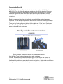
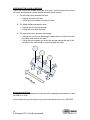
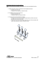
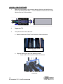
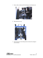
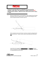
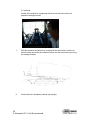
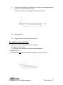
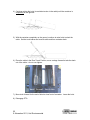
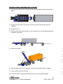
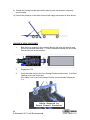
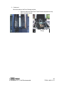
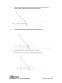
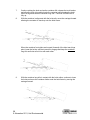
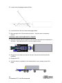
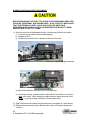
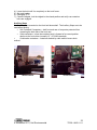
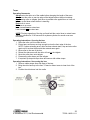
DuaLift
Hook and Cable
Combination Hoist
Operator’s
Manual
Failure to follow all instructions and
safety precautions in this manual, in the
Maintenance and Service Manual, in other
manufacturer’s manuals and on the
safety decals attached to the product
could result in serious injury or death to
operators or bystanders and/or damage
to property.
DO NOT operate this vehicle before you
READ and UNDERSTAND this Operator’s
Manual, the Parts and Service Manual for
this unit, other applicable manufacturer’s
manuals and the safety decals on the
product.
Each operator of this unit must read and
understand all directions in this manual
before they first operate this vehicle.
Keep this manual in the cab for new operators
and to remind all operators about safe use.
1
© Novemeber 2011, Heil Environmental
TP2DL-10002-1111
Read This Manual!
EVERY PERSON who will
OPERATE, MAINTAIN, REPAIR,
OR OTHERWISE WORK with the
Heil DuaLift Hook and Cable
Combination Hoist MUST READ
AND UNDERSTAND this entire
Operator’s Manual before starting
the engine or activating any switches
or controls. MAKE SURE to read
the Service Manual for the unit
BEFORE you do any maintenance
or repair procedures.
ALL USERS of this equipment must
be trained professionals who
understand how the machine
operates and know how to avoid the
risks associated with driving the
vehicle and with picking up,
compacting, and dumping refuse in
an ever-changing traffic
environment.
If you do not understand an
operation or instruction, seek
additional help or instruction from a
qualified source BEFORE you
operate the unit.
Organization of This Manual
This Operator’s Manual has eleven
(11) sections plus two appendices
and the Warranty Statement. Each
section has a specific set of topics
and information for the Heil Heil
DuaLift Hook and Cable Combination
Hoist (hereafter the DuaLift or the
unit).
Check sections etc and match words above
2
© November 2011, Heil Environmental
TP2DL-10002-1111
Introduction to the DuaLift
PAGE
Employer Responsibility
Operator/Employee Responsibilities
Standard Lockout/ Tagout Guidelines
Standard Lockout/Tagout Procedures
Service Hoist Props
Rear Underride Bar
Safety Precautions
Operating the DuaLift Cable and Hoist
Operating the PTO
Operating In-cab Controls
Operating Out-of-cab Controls
Loading a Cable Container
Unloading a Cable Container
Loading a Cable Container onto a Trailer
Loading a Hook Container
Unloading a Hook Container
Loading a Hook Container onto a Trailer
Dumping a Cable and Hook Container
Auxiliary Stops
Pintle Hook
Tarper
Warranty
4
5
6
7
8
9
11
12
13
14
15
16
21
23
24
29
30
32
33
34
35
41
3
© November 2011, Heil Environmental
TP2DL-10002-1111
EMPLOYER RESPONSIBILITIES
Upon purchasing the Heil Environmental DuaLift the owner has the following
responsibilities:
•
To comply with all occupational safety and health standards and all rules
and regulations set forth by the American National Standards for Refuse
Collecting and Compacting Equipment safety requirements. In addition,
all employers shall meet the terms of Title 49 Code of Federal
Regulations Parts 325-399, the Federal Motor Carrier Regulations
(FMCSR), and will ensure that any modifications to the chassis are done
in conformity with 49 CFR Part 571, the Federal Motor Vehicle Safety
Standards (FMVSS).
•
Provide supervised instruction and training of employees with regards to
the proper use, maintenance, safety and service as described in this
manual.
Allow only employees approved by the employer to operate or service the
vehicle.
•
•
Form a plan for regular equipment and safety checks to ensure that the
vehicle and all of its components are in good working order. These
periodic checks should also include operator competency tests and
retraining employees when they are introduced to new equipment.
•
Keep records of all training and certification of employees.
Also keep of all records of malfunctions, inspections, and maintenance.
•
The timely repair of any damaged or malfunctioning parts. All repairs and
checks must be completed before the vehicle is to return to normal
operation. NOTICE! A complete check should be performed on the
vehicle brought in for any repair.
•
Train employees that the hoist will not be used to lift or haul any weight
that is thought to be in excess of the load rating of any of the individual
components of the entire piece of equipment. (Ex: hoist, hook, tires,
chassis, suspension, etc.)
•
Direct that all manufacturer’s lockout and maintenance procedures are
followed. Subsequently that all safety precautions are taken not only
during both maintenance and lockout, but all procedures.
Assure that the operator of the hoist lift knows the load rating, minimum
overhead clearance and length of the vehicle with the container before
they take the vehicle for normal road travel. A sign must be affixed in the
cabin near the driver that states the minimum overhead clearance for the
vehicle and maximum height of the container/ compactor combination.
•
Verify all employees have been instructed and trained with regards to the
proper use, maintenance, safety, service and to maintain written
employee acknowledgement on file.
OPERATOR/ EMPLOYEE RESPONSIBILITY
4
© November 2011, Heil Environmental
TP2DL-10002-1111
Any employee that will be operate or service a DuaLift must become familiar with the
following responsibilities:
•
Adhere to all of the safety procedures and maintenance procedures
detailed by the manufacturer. No employee should operate the DuaLift
without the proper training with regards to the use, maintenance, safety
and service as described in the DuaLift Operator’s Manual.
•
Follow all instructions with regards to the lockout/tagout procedure as
described by the employer and manufacturer.
•
Report all damage or malfunctions to the employer or appropriate
person(s) as soon as possible.
•
When the hoist is in operation, the operator must make sure that the area
around the pickup or dump site is clear from any obstructions, people and
power lines.
•
The only suitable place for passengers is in the cab. Before operating or
putting the hoist into motion, the operator must make sure that no one is
riding on any other part of the vehicle.
•
The rear underride bar is in the horizontal position.
Please note: The owner/employer and operator/employee responsibilities listed are
only a guideline. There are other responsibilities, as dictated by the uniqueness of each
situation, for which the owner/employer and operator/employee are responsible.
ALL CABLE AND HOOK CONTAINERS USED WITH THE DUALIFT MUST
HAVE MATCHING SPECIFICATIONS WITH THE HOIST INCLUDING PROPER
HOOK HEIGHT, HOOK STYLE, AND CONTAINER TYPE.
THE DUALIFT IS SPECIFICALLY DESIGNED FOR THE OUTSIDE RAIL
CONTAINER SYSTEM. MODIFICATIONS OF THE DUALIFT TO
ACCOMADATE CONTAINERS OF THE DEADLIFT SYSTEM ARE NOT
AUTHORIZED OR RECOGNIZED BY THE MANUFACTURER.
NON-COMPLIANCE COULD RESULT IN SERIOUS INJURY OR DEATH.
5
© November 2011, Heil Environmental
TP2DL-10002-1111
STANDARD LOCKOUT/TAGOUT GUIDELINES
The lockout/ tagout procedure must locate all sources of energy and disable any energy
or pressure the vehicle may be storing from previous use. ALL LOCK OUT/ TAGOUT
CHECKS AND PROCEDURES MUST BE PERFORMED BY AN AUTHORIZED
EMPLOYEE TO PREVENT INJURY OR DAMAGE.
Execution of proper lockout/ tagout procedures is the responsibility of the employer/
owner and the employee/ operator.
ALL LOCKOUT PROCEDURES MUST BE FOLLOWED AND ALL SAFTEY
PRECAUTIONS MET. FAILURE TO DO SO COULD RESULT IN SERIOUS INJURY
OR DEATH.
1. Before starting any of the lockout/ tagout procedures notify all affected individuals
that you will be performing a lockout/tagout.
2. The equipment shall be tagged with signs stating that a lockout is underway and
that the equipment should not be activated while the signs are still in place. ALL
EMPLOYEES MUST BE FAMILIER WITH THE MEANING AND APPEARANCE
OF ALL SIGNS USED IN THE LOCKOUT PROCEDURE.
Requirements for lockout tags:
• Must be recognizable/ readable from at least 5 feet and have
coordinated distinct bright colors and patterns
• Must be visible and recognizable from all places of operation (i.e.
hoist controls, steering wheel, etc.)
• All signs/ tags must hold up and remain secured and readable through
the entire duration of the lockout and maintenance.
3. The keys shall be marked with tag stating that this vehicle is undergoing lockout.
The keys should then be placed in a safe easy to remember spot, such as the
operator’s pants pocket.
4. After all repairs and checks are completed only authorized personnel can release
the vehicle for normal operation.
5. The employer shall periodically supervise the lockout procedure performed by an
employee to ensure that all safety precautions and procedures are met. Vehicle
inspections by the employer after a lockout should also take place to make sure
the employee follows the correct practices.
6
© November 2011, Heil Environmental
TP2DL-10002-1111
ALL EMPLOYEES MUST BE ABLE TO RECOGNIZE ALL LOCKOUT SIGNS AND
MUST NOT ATTEMPT TO OPERATE ANY PART OF THE EQUIPMENT DURING A
LOCKOUT PRECEDURE UNLESS YOU ARE PERFORMING THE LOCKOUT
YOURSELF. IF YOU ARE UNSURE WHETHER OR NOT A LOCKOUT IS TAKING
PLACE, CHECK WITH YOUR EMPLOYER. FAILURE TO DO SO COULD RESULT IN
SERIOUS INJURY OR DEATH.
STANDARD LOCKOUT/TAGOUT PROCEDURE
The following is the standard lockout procedure for the DuaLift.
1. Set the parking brake and chock all of the wheels to prevent any unwanted
movement of the vehicle during maintenance.
2. Shut down any power sources like the engine and the Power Take Off (PTO).
3. Remove the keys from the ignition.
4. Put a tag on the steering wheel and other appropriate locations, such as
hydraulic controls, to prevent anyone from operating the vehicle or hoist.
5. Place operating equipment in such a way to prevent possible free fall of any
elevated equipment.
NOTE: ensure that both service hoist props have been properly aligned with the
retaining fixtures. Visually observe the props fall into place.
6. When performing maintenance on the hydraulic system, make sure that blocking
systems, such as service hoist props, are enabled before hydraulic pressure is
released.
NOTE: ALL LOCKOUT/TAGOUT PROCEDURES ARE IN ACCORDANCE WITH
ANSI Z245.1 – 1999. A COPY OF THIS DOCUMENT CAN BE ATTAINED BY
ORDERING IT ONLINE FROM http://webstore.ansi.org/ansidocstore/find.asp
OR REQUESTING A COPY FROM:
WASTE EQUIPMENT TECHNOLOGY ASSOCIATION
4301 Connecticut Avenue, NW, Suite 300, Washington, DC 20008
THE EMPLOYER SHOULD RETAIN A COPY OF THIS DOCUMENT FOR FUTURE
PERSONAL REFERENCE.
7
© November 2011, Heil Environmental
TP2DL-10002-1111
Service Hoist Props
REMOVE ANY CONTAINER FROM THE HOIST BEFORE PERFORMING ANY
MAINTENANCE ON THE VEHICLE. THE ADDED WEIGHT OF THE CONTAINER
COULD EXCEED THE MAXIMUM WEIGHT SUPPORTED BY THE SERVICE PROPS
CAUSING THEM TO BEND OR BREAK. FAILURE TO DO SO COULD RESULT IN
SERIOUS INJURY OR DEATH.
Operation:
1. Before raising the hoist, remove the service props from their retaining latch.
2. Raise the hoist and verify the service props hang straight down (vertical).
Lower the hoist and visually check to make sure that BOTH props are correctly
inserted into the retaining fixture. If the service props do not fall into place
inspect them to make sure they are not damaged. If damaged, DO NOT perform
any other maintenance until they are repaired and in good working order. If the
service props are not damaged then manually align them with the retaining
fixture.
8
© November 2011, Heil Environmental
TP2DL-10002-1111
THE SERVICE HOIST PROPS IN THE LOWERED POSITION ARE DESIGNED TO
PREVENT THE HOIST FROM FALLING IN THE EVENT OF A SUDDEN LOSS OF
HYDRAULIC POWER DURING SERVICE. NEGLECTING TO USE THE PROPS OR
IMPROPER USE OF THE PROPS COULD RESULT IN SERIOUS INJURY OR
DEATH.
Rear Underride Bar
The rear underride bar, located behind the tandem and underneath the rear end of the
tilt frame, is a safety device used to prevent vehicles from going under the tilt frame in
the occurrence of a collision.
Traveling without a trailer:
When traveling any distance without a trailer being towed it is necessary to make sure
that the rear underride bar is secured in the horizontal position shown below.
Illustration 1
9
© November 2011, Heil Environmental
TP2DL-10002-1111
Traveling with a trailer - continued:
The rear underride bar should be raised and pinned in the upward position as shown
below when traveling with a trailer attached to the pintle hook.
Raising and lowering the tilt frame:
When the hoist is operating, the rear underride bar will fold and unfold with the
movement of the hoist as shown below. However, before driving make sure the rear
underride bar is in the horizontal position as shown above in illustration 1.
10
© November 2011, Heil Environmental
TP2DL-10002-1111
SAFETY PRECAUTIONS
The following precautions do not encompass every situation that you might encounter,
however it is a good idea to keep them in mind when operating any part of the
equipment:
•
DO NOT use a chain, rope or any other connector between the cable or hook
and the container.
•
NEVER position yourself or anyone else at any time under or on top of any part
of the hoist or container.
•
NEVER drive or move the vehicle when the hoist or container or both are in the
upright/ raised position aside from loading/ unloading hoist activities.
•
DO NOT allow the cable to become slack during either the loading or unloading
process, because the cable could disconnect from the container.
•
NEVER lock a control handle to stay in position; the valves are designed to
return to center when released.
•
ALWAYS power down the hoist. NEVER let the weight of the container lower the
hoist.
•
NEVER drive the vehicle when the PTO is engaged.
•
In cold weather allow the hydraulic oil to warm up before use. Do this by
engaging the PTO and letting the vehicle idle for a few minutes.
•
NEVER drive the vehicle unless all safety latches are engaged and the rear
underride bar is horizontal.
•
NEVER leave the vehicle unattended while the engine is still running.
•
MAKE SURE that all safety stickers and decals are readable.
•
REMOVE any container before maintenance.
•
ALWAYS engage BOTH safety props when accessing the area under the raised
tilt frame.
11
© November 2011, Heil Environmental
TP2DL-10002-1111
Operating the DuaLift
The DuaLift has the capability to load and unload cable outside rail ANSI Standard
ANSI 245.6 Type U containers and hook containers with a lift bar height of 62 inches.
The operation procedure in loading and unloading cable containers is very similar to
traditional outside rail roll off cable hoists as is the loading and unloading of hook
containers. Further attention is required when the route is mixed with cable and hook
containers.
Read the operating instructions to familiarize yourself with the required operational
sequence. Do not attempt to operate the hoist without a thorough operating knowledge.
There are two fixed positions on the hoist for the cable end: Front Travel Position and
Rear Travel Position. The Front Travel Position is the required position for the cable
when servicing all hook containers.
Hook Container = cable end secured to Front Storage Position.
Use the Rear Travel Position when servicing cable containers.
Caution: When switching between container types use the tray on the carriage to
transport cable and cable end back and forth. Remember not to extend the carriage
forward with the cable end secured in the rear travel position. Failure to do so will cause
damage to cable rear travel hook and may damage cable and cable end.
12
© November 2011, Heil Environmental
TP2DL-10002-1111
OPERATING THE PTO
OPERATING THE PTO WITH A MANUAL TRANSMISSION
Shifting the PTO into gear
1.
2.
3.
4.
Engage Clutch
Wait for transmission to stop rotating
Shift PTO into gear
Disengage clutch.
Shifting the PTO out of gear
1.
2.
3.
4.
Engage Clutch
Wait for PTO to stop rotating
Shift PTO out of gear
Disengage clutch.
OPERATING THE PTO WITH AN AUTOMATIC TRANSMISSION
Shifting the PTO into gear
1. Shift PTO into gear.
Shifting the PTO out of gear
1. Shift the PTO out of gear.
13
© November 2011, Heil Environmental
TP2DL-10002-1111
OPERATING THE IN-CAB CONTROLS
The In-Cab Controls are located next to the driver seat. Use the picture below to help
you locate and familiarize yourself with the operation these controls.
1. The left-most control operates the hook.
•
•
Pushing this lowers the hook.
Pulling the lever towards you raises the hook.
2. The Middle handle operates the hoist.
•
•
Pushing the lever lowers the hoist.
Pulling the lever raises the hoist.
3. The right-most control operates the carriage.
•
•
Pushing the lever moves the carriage towards the front of the truck and in
the cable mode retracts the cable.
Pulling the lever towards you moves the carriage towards the rear of the
truck and in the cable mode to extend and slack the cable.
Accelerating the Engine
The engine can be accelerated from inside the cab by pressing the accelerator to raise
the RPM up to 1500.
Cruise control can also be used so long as the cruise speed is set up for 1500 RPM.
14
© November 2011, Heil Environmental
TP2DL-10002-1111
OPERATING THE OUT-OF-CAB CONTROLS
The out-of-cab controls are located on the left side of the truck just behind the driver
door.
1. When facing the Controls, the left-most control operates the hook.
• Pushing lowers the hook.
• Pulling the lever towards you raises the hook.
2. The Middle handle operates the hoist.
• Pushing lowers the hoist.
• Pulling the middle lever raises the hoist.
3. The rear-most control operates the carriage.
• Pushing the lever moves the carriage towards the front of the truck and in
the cable mode retracts the cable.
• Pulling the lever moves the carriage towards the rear of the truck and in the
cable mode extends the cable or slacks the cable.
15
© November 2011, Heil Environmental
TP2DL-10002-1111
LOADING A CABLE CONTAINER
1.
Back the truck squarely to the container aligning the hoist rails with the long
sills on the container and allow 1 - 2 feet of clearance between the end of the
hoist and the end of the container.
2.
Engage the PTO.
3.
Verify the location of the cable end:
a. With the cable end at Rear Travel Position, follow instruction 4.
Cable End in Rear Travel
Position
b.
With the cable end in the Front Storage Position:
i. Un-pin cable end and position cable over sheave.
Cable End in Front Travel
Position
16
© November 2011, Heil Environmental
TP2DL-10002-1111
ii. Secure cable on sheave with Front Storage pin and retainer clip.
iii. Place cable end in tray.
Tray
iv. Verify the hook is in the vertical position and move the carriage to
rear of tilt frame.
17
© November 2011, Heil Environmental
TP2DL-10002-1111
4.
Raise tilt frame until the tail nearly touches the ground (do not lift rear frame
of truck off the ground with the tail of the hoist.)
5.
Set the truck brakes and connect the cable end to the container hook.
Front rollers - cable container
18
© November 2011, Heil Environmental
TP2DL-10002-1111
Check to be sure the cable end is attached and in good working
condition. If the cable or the connection is frayed or broken do NOT
attempt to lift a container. Failure to do so could result in serious injury
or death.
6.
Move the carriage forward. As the container is lifted, release the truck brakes
and allow the truck to be pulled under the container while keeping the hoist
rollers in alignment with the container long sills.
As the container moves onto the hoist, continue moving the carriage forward
and lower the hoist. Continue until the rollers travel beyond the hoist hinge.
Lower the hoist to engage the container long sills and hoist rails with each
other and releasing the brake will allow the truck to roll under the container as
it is moved further up onto the hoist.
19
© November 2011, Heil Environmental
TP2DL-10002-1111
6. Continued
Confirm the container is in alignment with the hoist rails and continue to
extend the carriage forward.
7.
With the container long sills are in contact with the hoist rollers, continue to
lower the hoist and move the container further onto the hoist frame by moving
the carriage forward.
8.
Verify the hook is completely vertical (up straight).
20
© November 2011, Heil Environmental
TP2DL-10002-1111
9.
With the hoist completely on the truck frame, continue to retract the carriage
all the way to the front end of the hoist.
Verify front container rollers engage in hoist front hold downs.
10.
Disengage PTO.
11.
Engage the rear container hold-down device.
A
UNLOADING A CABLE CONTAINER
1) Back the truck into the designated area for unloading:
a) Engage the truck brakes.
b) Remove the rear tie downs from the hoist and the container.
2) Engage the PTO.
3) Raise the hoist and move the carriage all the way to the rear of the hoist.
21
© November 2011, Heil Environmental
TP2DL-10002-1111
4) Continue raising the hoist (to maintain tension in the cable) until the container is
completely on the ground.
5) With the container completely on the ground, continue to raise hoist to slack the
cable. Set the truck brakes and remove cable end from container hook.
6) Place the cable in the Rear Travel Position, move carriage forward to take the slack
out of the cable – do not over tighten.
Rear Travel Position
7) Move truck forward for the end of hoist to clear front of container. Lower the hoist .
8) Disengage PTO.
22
© November 2011, Heil Environmental
TP2DL-10002-1111
A
LOADING A CABLE CONTAINER ONTO A TRAILER
1) Align the hoist rails with the long sills on the truck and back the truck squarely to the
trailer.
2) Engage the truck brakes and remove the rear tie downs from the hoist and the
container.
3) Engage the PTO.
4) With the hook in the vertical position, move carriage to rear of hoist frame placing the
container on the trailer.
C
A
B
L
E
5) Raise the tilt frame.
6) When the container rests on the trailer bed remove the cable from the container.
7) Lower the hoist onto the tilt frame.
8) Lower the mast to the horizontal position so that it is completely horizontal.
23
© November 2011, Heil Environmental
TP2DL-10002-1111
9)
Extend the Carriage cylinder and use the mast to push the container completely
onto the trailer.
10) Secure the container on the trailer for travel with cargo securement tie down device.
LOADING A HOOK CONTAINER
1.
Back the truck squarely to the container aligning the hoist rails with the long
sills on the container and allow 1 - 2 feet of clearance between the end of the
hoist and the end of the container.
2.
Engage the PTO.
3.
Verify the cable end is in the Front Storage Position shown below. If so Move
Carriage to the rear of tilt frame.
If the cable is not in the Front Storage Position; move the cable forward per
3. a.
Cable Secured in
Front Travel Position
24
© November 2011, Heil Environmental
TP2DL-10002-1111
3. – Continued
Move the cable to the Front Storage position:
i. Remove cable end from Rear Travel Position and place on tray.
Move carriage forward.
Cable End in
Tray
25
© November 2011, Heil Environmental
TP2DL-10002-1111
ii. Rotate hook down to gain access and un-pin cable from sheave,
place cable end into Front Storage Position.
Remove sheave pin
and retainer clip.
Cable end position for all
hook operations.
Secure cable end with
the sheave pin and
retainer clip.
Front Storage Position
26
© November 2011, Heil Environmental
TP2DL-10002-1111
4.
Raise tilt frame until the tail nearly touches the ground (do not lift rear
frame of truck off the ground with the tail of the hoist).
5.
Rotate hook down to a height below the container lift bar.
6.
Raise hoist until tail of hoist is firmly on the ground.
Back the truck and raise hook engaging container lift bar.
27
© November 2011, Heil Environmental
TP2DL-10002-1111
7.
Continue raising the hook and as the container lifts, release the truck brakes
and allow the truck to be pulled under the container while keeping the hoist
rollers in alignment with the container long sills. Continue until the hook is
fully up.
8.
With the container in alignment with the hoist rails, move the carriage forward
allowing the container to travel up onto the hoist frame.
When the container front rollers are beyond (forward) of the hoist rear hinge
point, lower the hoist a sufficient amount to engage and keep the container
long sills and hoist rails in line with each other.
9.
With the container long sills in contact with the hoist rollers, continue to lower
the hoist and move the container further onto the hoist frame by moving the
carriage forward.
28
© November 2011, Heil Environmental
TP2DL-10002-1111
10.
With the hoist completely lowered on the truck frame, continue to move the
carriage to the full forward travel position. Verify the hook is completely
vertical.
11.
Disengage PTO.
12.
Engage the rear container hold-down device.
UNLOADING A HOOK CONTAINER
1) Back the truck into the designated area for unloading and engage the truck brakes.
2) Release the rear tie downs from the hoist and the container.
3) Engage PTO.
4) Raise the hoist to the angle as shown below and move the carriage to the rear of the
hoist. As the rear of the container touches the ground, release brakes and allow
truck to roll forward and continue to raise hoist until tail roller engages ground.
29
© November 2011, Heil Environmental
TP2DL-10002-1111
5) Lower hook to disengage container lift bar.
6) Lower the hoist to the truck frame and engage brakes.
7) Move carriage to the full forward travel position. Verify the hook is completely
vertical.
LOADING A HOOK CONTAINER ONTO A TRAILER
1) Align the hoist rails with the long sills on the container and back the truck squarely to
the trailer. Verify that the truck is on a level compact surface.
2) Engage the truck brakes and remove the rear tie downs from the hoist and the
container.
3) Engage the PTO.
4) Verify the hook is completely in the vertical position, move carriage to rear of tilt
frame.
30
© November 2011, Heil Environmental
TP2DL-10002-1111
5) Raise the tilt frame and rotate the hook downward to move the container horizontally
onto the trailer.
6) Rotate the hook below horizontal to disengage the mast hook from the container lift
bar.
7) Secure the container on the trailer for travel with cargo securement tie down device.
31
© November 2011, Heil Environmental
TP2DL-10002-1111
DUMPING CABLE and HOOK CONTAINERS
BEFORE ENGAGING THE HOIST PTO CHECK THE SURROUNDING AREA FOR
VEHICLES, PERSONNEL, AND POWER LINES. ALSO, CHECK TO MAKE SURE
THAT THE TERRAIN IS LEVEL, SOLID, AND CLEAR OF OBSTICALS.
DETERMINE HOW FAR BACK THE CONTAINER MUST BE MOVED TO DUMP
DEBRIS FREE OF THE TILT FRAME.
1) Back the truck into the designated area for unloading and set the truck brakes.
a) Verify the rear container locks are not engaged.
b) Engage the PTO.
c) Determine if the end of box is forward of the end of the hoist,
if so, move container to the rear of the frame by moving the carriage rearward,
so debris falls behind the hoist and not on the hoist frame.
d) Note when pushing a cable container rearward one foot results in one foot of
slack in the cable. When emptying a cable container always keep the cable
taught, by moving carriage forward to eliminate cable slack.
2) Open and secure the container tailgate and secure the tailgate in a safe manner.
3) Release the brakes and raise the hoist and drive the truck forward dumping the
contents.
32
© November 2011, Heil Environmental
TP2DL-10002-1111
4)
5)
6)
7)
Lower the hoist until it is completely on the truck frame.
Set truck brakes.
Disengage PTO.
Close the tailgate, lock the tailgate in the closed position and verify rear container
locks are engaged.
Auxiliary Stops
Auxiliary Stops are mounted on the front hold down shaft. The Auxiliary Stops are to be
used when hauling:
• Self Contained Compactors – both front and rear of compactor protected from
contacting the back side of the hook arm.
• Cable containers – when the container hook is forward of its normal position
relative to the front rollers (normally 16” -18” ANSI standard).
•
Combination containers – containers hauled by cable method versus hook
method.
Stored Position
In-use Position
33
© November 2011, Heil Environmental
TP2DL-10002-1111
Pintle Hook
Operating Instructions:
1. Deactivate the plunger by removing the air pressure. Check to see that the
plunger (XA-04156) is retracted.
2. Before using pintle hook, inspect for proper operation; worn, damaged or missing
parts; and a secure mounting. Correct as required for use.
3. Open latch (XA-02536) by pushing the handle (XA-01534-1) to the left and
rotating it down. While keeping the handle rotated down, lift the latch open.
4. Position the drawbar eye over the horn of the pintle and lower it into place.
5. Push the latch closed. Verify that the primary and secondary locks engage (see
figure below).
6. Extend the plunger by applying air pressure.
Maintenance:
For proper performance, the following maintenance steps should be performed every
30,000 miles or 3 months, whichever comes first.
1. Clean and check for proper operation. Inspect for worn, damaged or missing
parts. Replace as required.
2. Inspect, in particular, the coupling contact area. Replace when wear exceeds
1/8” (0.125”) from the original surface profile.
3. Lubricate latch pivots with a light oil lubricant.
4. Check mounting fasteners for proper torque.
5. Check plunger adjustment. When properly adjusted, the plunger should tightly
grip a 1.25” round bar when energized (see figure below) and retract far enough
when de-energized to allow easy removal of the drawbar.
34
© November 2011, Heil Environmental
TP2DL-10002-1111
Tarper
Operating Comments:
Always raise the roller out of the cradle before changing the length of the arms.
Always rest the roller on rear top edge of the tailgate and not beyond container.
Upon resting roller on tailgate, push lever to preload roller against box so it will not
bounce up and down when the box is traveling.
Push lever to cover.
Pull lever to un-cover.
Lever toward front to extend arm.
Lever toward rear to retract arm.
NOTE: First tarp operation of the day; pull and hold the control lever to retract lower
side arm cylinders for 15-20 seconds to re-phase cylinders for smooth even arm
movement.
Operating Instructions: Covering the box
1. Raise the roller until it touches the box.
2. Extend arms until arms are long enough to clear the front edge of the box.
NOTE: If when extending arms, roller touches exhaust stack, stop and raise roller
again until it touches the box and then extend arms again.
3. Move roller to the rear of the box.
4. Retract the side arms until the roller will rest on the tailgate.
5. Move the roller down onto tailgate.
6. Pressure the roller down onto the tailgate.
7. If required, flip tarp side flaps down and secure with rubber straps.
Operating Instructions: Uncovering the box
1. Remove rubber straps from side flaps of the tarp.
2. Bring the roller back up to the front. Extend or retract arms to clear front of the
box.
3. Position the roller down into the cradle.
35
© November 2011, Heil Environmental
TP2DL-10002-1111
36
© November 2011, Heil Environmental
TP2DL-10002-1111
APPENDIX A
MAINTENANCE CHART
AND
ILLUSTRATION
37
© Novemeber 2011, Heil Environmental
TP2DL-10002-1111
INSPECTION AREAS
Daily
Weekly
3 mo.
6 mo.
1 yr.
Check Hydraulic Oil levels
X
X
X
X
X
Hydraulic components
X
X
X
X
X
Hydraulic oil leaks
X
X
X
X
X
Rollers, Rear hinge, Pivot Points,
X
X
X
X
X
Sheave
Nuts & bolts
X
X
X
X
X
Electrical wiring
X
X
X
X
X
Back up and hoist up warnings
X
X
X
X
X
Structural components
X
X
X
X
X
Front and rear container hold downs
X
X
X
X
X
Cable, Mast and Hook
X
X
X
X
X
Control rod or cable linkage
X
X
X
X
X
Shafts and Cotter pins
X
X
X
X
X
Pintle Hook
X
X
X
X
X
Lights, Reflectors
X
X
X
X
X
Warning Decal Inspection
X
X
X
X
X
Hoist Frame and hinge
X
X
X
X
X
-----------------------------------------------------------------------------------------------------------Grease all grease fittings(refer to
X
X
X
X
pg.##)
Check Hydraulic filter
X
X
X
X
Check Hydraulic breather
X
X
X
X
-----------------------------------------------------------------------------------------------------------Inspect the condition of hydraulic oil for
X
X
X
proper color, odor and feel
-----------------------------------------------------------------------------------------------------------Replace air breather
X
Replace hydraulic oil filter
X
-----------------------------------------------------------------------------------------------------------Clean suction strainer
Replace hydraulic oil
38
© November 2011, Heil Environmental
X
X
X
X
TP2DL-10002-1111
HOOK PIVOT, 2
HINGE PIN, 2
ROLLER PIN, 10
HOIST CYL BASE
HOIST CYL ROD END,
HOOK CYL ROD END, 2 PLCS
CARRIAGE CYL ROD
HOOK CYL BASE END, 2 PLCS
CARRIAGE
CARRIAGE
CYL
BASECYL
END PIN
SHEAVE PIN
HIGH PRESSURE HYD FILTER
39
© November 2011, Heil Environmental
TP2DL-10002-1111
THIS PAGE INTENTIONALLY LEFT BLANK
40
© November 2011, Heil Environmental
TP2DL-10002-1111
HEIL ENVIRONMENTAL DUALIFT WARRANTY STATEMENT
Heil Environmental (“Heil”) d/b/a DuaLift warrants its solid waste collection equipment to
be free from defects in material and workmanship under normal single-shift use for a
period of twelve (12) months or 2000 hours of operation (whichever comes first) from
the date of equipment invoicing or during the period of coverage offered by an extend
warranty program, when operated in accordance with its Operator’s Manual and proper
service and maintenance as described in DuaLift Service Bulletins and Parts and
Service Manuals are performed. The standard or extended equipment warranty is not
transferable except for sales demonstration units.
This warranty is expressly limited to the repair or replacement of any component or part
thereof, of any such DuaLift product manufactured by Heil that is proven to Heil’s
satisfaction to have been defective in material or workmanship. Such components or
parts shall be repaired or replaced at Heil’s option without cost to the standard
purchaser for parts and labor provided such units is returned to an authorized DuaLift
Dealer for replacement or repair. The repair or replacement must be made during the
standard or extended warranty coverage period.
All OEM service parts sold by Heil for the DuaLift product line have a six (6) month
warranty from the date of purchase. Aftermarket parts purchased from Heil are
supported by a 90-day warranty. The parts warranty covers parts only, provided that
factory inspection reveals a defect in material or workmanship. Labor, troubleshooting,
equipment downtime, etc. is not covered under the parts warranty policy.
HEIL MAKES NO OTHER WARRANTY, EXPRESSED OR IMPLIED, AND MAKES
NO WARRANTY OF MERCHANTABILITY OR OF FITNESS FOR ANY PARTICULAR
PURPOSE. HEIL DOES NOT ASSUME ANY LIABILITY OR ACCEPT CLAIMS FOR
LOSS OF PROFITS, PRODUCT DOWN TIME OR ANY OTHER DIRECT,
INCIDENTAL OR INDIRECT CONSEQUENTIAL LOSSES, COSTS, DAMAGES OR
DELAYS.
Any improper use, operation beyond rated equipment or component capacity,
substitution of parts that are not Heil approved, or any alteration or repair by others in
such manner as in Heil’s sole judgement affect the product operation or integrity shall
void the warranty.
Other than the extension of the standard warranty period purchased under a
supplemental Heil Extended Warranty Program, no employee or representative is
authorized to modify this warranty in any way nor shall any other warranties be granted.
No dealer-supplied warranty program is endorsed or supported by Heil.
All warranty activity must the processed through an authorized Heil Environmental
Dealer or Service Center.
Heil retains the right to modify its factory warranty program prospectively at any time.
41
© November 2011, Heil Environmental
TP2DL-10002-1111
www.heil.com
Customer Care Phone:
866-ASK-HEIL
(866-275-4345)
Parts Central Phone:
800-528-5308
Technical Service Phone:
866-310-4345
Customer Support
Heil Environmental
4301 Gault Avenue North
Fort Payne, AL 35967-9984
42
© November 2011, Heil Environmental
TP2DL-10002-1111