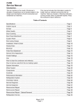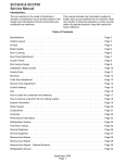
1
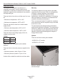
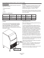
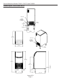
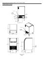
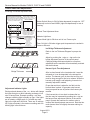
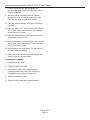
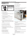
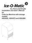
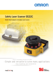
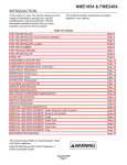
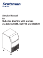
Service Manual
for
Cube Ice Machine with storage
models CU0415, CU0715 and CU0920
Service Manual for Models CU0415, CU0715 and CU0920
Introduction
The design of this product is the result of years
of experience in developing commercial ice cube
machines. It has been designed for simple operation
in a wide range of locations. Please follow the
instructions for installation and maintenance to get the
most use from this ice machine.
Table of Contents
Performance . . . . . . . . . . . . . . . . . . . . . . . . 16
Important Details. . . . . . . . . . . . . . . . . . . . . 2
Thermistor Values. . . . . . . . . . . . . . . . . . . . 17
Pre-Installation. . . . . . . . . . . . . . . . . . . . . . .3
Controller Use. . . . . . . . . . . . . . . . . . . . . . . 18
Cabinet Layout, CU0415 and CU0715 . . . . 4
Anti-Slush . . . . . . . . . . . . . . . . . . . . . . . . . . 19
Cabinet Layout, CU0920. . . . . . . . . . . . . . . 5
Service Diagnosis. . . . . . . . . . . . . . . . . . . . 21
Component Location. . . . . . . . . . . . . . . . . . 6
Service Diagnosis. . . . . . . . . . . . . . . . . . . . 22
Connect the water supply . . . . . . . . . . . . . . 7
Service Diagnosis. . . . . . . . . . . . . . . . . . . . 23
Connect the power . . . . . . . . . . . . . . . . . . . 8
Removal and Replacement. . . . . . . . . . . . . 24
Control Panel and Adjustments. . . . . . . . . . 9
Removal and Replacement. . . . . . . . . . . . . 25
Initial Start Up . . . . . . . . . . . . . . . . . . . . . . . 10
Removal and Replacement. . . . . . . . . . . . . 26
Use and Operational Notes. . . . . . . . . . . . . 11
Controller. . . . . . . . . . . . . . . . . . . . . . . . . . . 27
Maintenance . . . . . . . . . . . . . . . . . . . . . . . . 12
Cabinet Removal for Service. . . . . . . . . . . . 28
Electrical Sequence. . . . . . . . . . . . . . . . . . . 14
115/60/1 Wiring Diagram. . . . . . . . . . . . . . . 29
Components . . . . . . . . . . . . . . . . . . . . . . . . 15
Observe the Caution and Warning notices. They are
indicators of important safety information. Keep this
manual for future reference.
August 2013
Page 1
Service Manual for Models CU0415, CU0715 and CU0920
Important Details
The machine is designed for use indoors in a
controlled environment. It must be kept dry, not
overheated or subjected to excessive cold. The water
and power supply must be maintained or the machine
will stop making ice.
There are limits to how hot or cold the room it’s in can
be.
• Minimum air temperature: 50oF or 10oC
The warranty statement for this product is provided
separately from this manual. Refer to it for applicable
coverage. In general warranty covers defects
in material or workmanship. It does not cover
maintenance, corrections to installations, or situations
when the machine is operated in circumstances that
exceed the limitations printed above.
This is a commercial model, if installed in a residence
some commercial service companies may not be able
to service it on site.
• Maximum air temperature: 100oF or 38oC.
There are also limits to how hot or cold the water
supply can be:
The manufacturer has designed and produced this
machine with the finest in materials. The manufacturer
assumes no liability for units that have been altered in
any way. Alterations or part substitutions will void the
warranty. Specifications and designs are subject to
change without notice.
• Minimum water temperature: 40oF or 4.5oC
• Maximum water temperature: 100oF or 38oC.
There are limits to the voltage supply to the unit,
voltages vary by model:
Options:
Voltage
Minimum
Maximum
Warranty:
115 (-1)
There are two floor mounting kits available:
104
126
• KUFM15: for 15” models
• KUFM20: for 20” model
Water supply must be potable by the localities
definition.
There are limits to the water pressure supplied to the
unit:
• Maximum pressure. static: 80 psi or 5.5 bar
• Minimum pressure, dynamic: 15 psi or 1 bar
A drain will be needed for melted ice and rinse water.
Bottom of Cabinet, showing bumper. Cabinet height
includes bumper.
August 2013
Page 2
Service Manual for Models CU0415, CU0715 and CU0920
Pre-Installation
Spacing:
This appliance is intended to be used in commercial
applications including:
No additional spacing is required at the top or sides.
However, suggested minimum side clearance for
installation is 1/8 inch or 3 mm and suggested
minimum top clearance is 1/4 inch or 7 mm.
• Restaurant kitchens
• Bars
Allow 4 inches (100 mm) minimum space at the back
for the utility connections. Do not block louvers at the
front of the cabinet.
• Hotels
Dimensions and Electrical:
Model
Electrical
(volts/Hz/Phase
Width
(in / cm)
Depth
(in/cm)
Height (w/o legs) Total Load
(in/cm)
Amps
CU0415MA-1A
115/60/1
15 / 38
23.7 / 60.3
31.94 / 81.1
8
CU0715MA-1A
115/60/1
15 / 38
23.7 / 60.3
31.94 / 81.1
8
CU0920MA-1A
115/60/1
20 / 51
23.7 / 60.3
31.94 / 81.1
8
Unpacking and setup
Location:
The unit can be built into a cabinet as the air flow
is in and out the front. The front of the machine
must not be blocked. Certain maintenance or
repair procedures will require removal of the top,
back and side panels, so plan ahead for service and
maintenance needs.
Remove all shipping and packing materials that may
be in the ice storage bin.
The unit can be installed with or without legs. The
cabinet is equipped with small bumpers on the base
to allow placement without legs. An optional floor
mounting kit is also available to fill the gap between
the machine and floor if not using legs. If using legs,
carefully tip the machine and install the legs by
screwing them into the leg sockets in the bottom of
the machine. For reference, the thread size is 5/8 –
11. If the machine has been tipped onto its side or
back allow 1 hour before starting the unit for the oil in
the refrigeration system to return to the compressor.
Place the machine in its intended location and level it
front to back and left to right. If using legs, adjust their
feet in and out to level the cabinet.
Air IN
If legs are not used the bottom edges of the cabinet
must be sealed to the floor.
If built into a cabinet, the adjacent cabinet walls will
provide the means for containment. There are no
means for attachment to the cabinet.
Be sure to remove the plastic covering the exterior panels,
if left on it will be much harder to remove later.
Air OUT
August 2013
Page 3
Service Manual for Models CU0415, CU0715 and CU0920
Cabinet Layout, CU0415 and CU0715
POWER CORD
POTABLE
WATER INLET
1/4" OD. PLASTIC
TUBING (5ft)
DRAIN
3/4" FPT
14.6cm
5.8in
5.1cm
2.0in
8.2cm
3.2in
34.5cm
13.6in
60.3cm
23.7in
POWER CORD
POTABLE
WATER INLET
1/4" OD. PLASTIC
TUBING (5ft)
38.1cm
15.0in
DRAIN
3/4" FPT
81.1cm
31.9in
95.4cm
37.6in
68.9cm
27.1in
10.2cm
MINIMUM
UTILITY
CLEARENCE
AIR
OUTLET
AIR
INLET
15.2cm
6.0in
29.8cm
11.8in
48.3cm
19.0in
August 2013
Page 4
Service Manual for Models CU0415, CU0715 and CU0920
Cabinet Layout, CU0920
POWER CORD
POTABLE
WATER INLET
1/4" OD. PLASTIC
TUBING (5ft)
DRAIN
3/4" FPT
14.6cm
5.75in
7cm
2.75in
5.1cm
2.00in
8.2cm
3.23in
32cm
12.60in
POWER CORD
60.1cm
23.67in
POTABLE
WATER INLET
1/4" OD. PLASTIC
TUBING (5ft)
50.8cm
20.00in
DRAIN
3/4" FPT
81.1cm
31.94in
95.4cm
37.56in
10.2cm
4.00in
MINIMUM
UTILITY
CLEARENCE
68.9cm
27.13in
AIR
OUTLET
AIR
INLET
15.2cm
6.00in
42.5cm
16.75in
48.3cm
19.00in
August 2013
Page 5
Service Manual for Models CU0415, CU0715 and CU0920
Component Location
Cube Deflector
Curtain
Bin
Thermostat
Sensing
Point
Thermostat
Condenser Fins
Drain Plug
Bin Thermostat Adjustment
Controller
Condenser Fan
Control Area
August 2013
Page 6
Service Manual for Models CU0415, CU0715 and CU0920
Connect the water supply
Connection Information:
Plumbing information:
WARNING: connect to potable water supply only.
• The water supply connection is at the back panel. It
is a 5’ (1.5 meter) 1/4 inch (6.35 mm) OD plastic tube.
Important: Open the hand water valve to flush
water through the connection point before
connecting to the ice machine.
• A hand actuated valve within site of the machine is
required to isolate the unit when it’s being serviced.
• The machine has a built-in back flow preventer (an
air gap between the end of the water inlet hose and
the top of the reservoir water), no additional back flow
preventer is needed.
• Water flow rate into machine is .25 GPM / .94 LPM.
Units that are built into a cabinet:
Include a loop or coil of tubing between the water
supply and the connection on the ice machine. When
the machine is pushed back into the cabinet the
tubing will coil and not kink.
Potable Water Inlet Tube
1. Cut cable ties securing hose and power cord to
unit.
2. Connect to cold, potable water using the
necessary adapters for the 1/4 inch OD plastic
tube.
• If using compression fittings they require a ferrule or
sleeve and insert.
• A female 3/8 compression adapter x 1/4 OD
compression allows connection to a typical 3/8 OD
compression angle valve.
• Another connection method is by quick connect
fittings.
Note: Do not use a piercing-type saddle valve to
connect to the building’s water supply. Valves of
that type restrict water flow and clog easily.
Connect the drain
The drain connection is at the back panel. The fitting
size is ¾ FPT.
1. Connect rigid tubing to this fitting and vent it at the
machine, use an 8 inch or 200 mm vertical tube
for the vent.
2. Slope drain tubing down from the ice machine to
the building drain and the slope must be at least ¼
inch per foot or 20 mm per meter.
3. Insulate the drain tubing to reduce condensation
and is recommended for environments that have
high humidity.
Due to the potential for leaks, condensate pumps are
not recommended.
Drain Fitting, 3/4 FPT
August 2013
Page 7
Service Manual for Models CU0415, CU0715 and CU0920
Connect the power
This is a cord-connected unit, and must be connected
to its own dedicated power supply. Check the
dataplate on the back of the machine to confirm the
voltage and per the dataplate use fuses or HACR
circuit breakers.
Power Cord:
This 115 volt model is equipped with a cord and 5-15P
plug.
Follow All Local Codes - This Unit Must Be
Grounded. Do not use extension cords and do not
disable or by-pass ground prong on electrical plug.
Plug the power cord into the proper power supply.
Installation check list
• Has the machine been installed indoors in an
environment suitable for it?
• Have all of the shipping items and packaging been
removed?
• Has the plastic covering the exterior panels been
removed?
Front view of freezing compartment, right arrow points
to Spray Platform, under the Cube Deflector. Push
curtain back and check that it is in this position.
Left arrow points to Cube Deflector, it must be
positioned as shown, it snaps onto front edge of
reservoir. Remove any packing materials.
• Is the ice chute in the correct position?
• Is the clear plastic curtain hanging down and free to
move?
• Has the water supply been connected and
confirmed to not leak?
• Has a properly sized and sloped drain tube been
attached?
• Has the correct voltage power supply been
connected?
Curtain
Front view of freezing compartment, arrow points to
clear plastic curtain. After checking spray platform,
pull curtain down to hang freely. This is its normal
position.
August 2013
Page 8
Service Manual for Models CU0415, CU0715 and CU0920
Control Panel and Adjustments
Ice Bridge Thickness Adjustment Area
Ice Bridge Thickness Adjustment
Réglage de l'épaisseur du pont de glace
Ajuste del espesor del puente de hielo
Regolazione spessore ponte di ghiaccio
Anpassung der Eisbrückendicke
-
ON / OFF / WASH
MARCHE / ARRÊT / LAVAGE
ENCENDIDO / APAGADO / LAVADO
ON / OFF / LAVAGGIO
EIN / AUS / WASCHEN
+
+
Harvest Time Adjustment
Réglage du temps de récolte
Ajuste del tiempo de cosecha
Regolazione orario di raccolta
Anpassung der Erntezeit
Freeze Mode
Harvest Time Adjustment Area
Indicator Light Area.
Mode de congélation
Modo de congelamiento
Modalità congelamento
Gefriermodus
Freeze Mode light is ON when unit is in a Freeze cycle.
Minuterie allumée
Cronómetro encendido
Timer attivato
Timer eingeschaltet
Timer On light is ON when trigger point temperature is reached in
Freeze or Harvest.
Timer On
17-3386-01
Master Switch. Move to ON (left side depressed) to make ice, OFF
(centered) to shut off and WASH (right side depressed) for use in
cleaning.
Ice Bridge Thickness Adjustment
Ice Thickness Diagram
Refer to the Ice Thickness Diagram for proper ice
size.
Ice Too Thin
Adjust by pushing the + sign or – sign on the ice
bridge adjustment section of the control panel.
Changing bridge thickness should be a one-time
adjustment as the machine will automatically maintain
that ice thickness.
Ice Just Right
Harvest Cycle Time Adjustment
Bridge Thickness
After ice has formed in the inverted mold, it must be
released so it can be deposited in the storage bin
section. The harvest cycle is when that occurs, and
must be long enough for the ice to release. While the
harvest cycle length is self adjusting it can also be
manually adjusted if needed.
Ice Too Thick
Adjustment Indicator Lights
Each push and release of the + or - button will change
the lights that glow or blink indicating a change in ice
size or harvest time. Example: pushing + one time
changes a blinking light to steady on type. If the lights
are on steady a single push of + will add one more
light to the right and it will blink. There are 10 settings.
All 5 lights on steady is the maximum setting and one
blinking light is the minimum.
Proper harvest time is when the ice falls into the
bin and there is about 10 seconds extra harvest
time (pump and fan are off) before the freeze cycle
restarts.
If the harvest time is too short to release the ice,
the time may be increased by pushing the + sign on
the harvest time adjustment section of the control
panel. Operate the machine for another cycle to
confirm that the adjustment was correct. Note that too
much harvest time will slightly decrease making ice
capacity.
August 2013
Page 9
Service Manual for Models CU0415, CU0715 and CU0920
Initial Start Up
1. Remove the front panel by removing the two
screws holding it to the cabinet and pulling the
panel down and off the machine.
2. Turn on the water supply, correct any leaks.
Note: Water supply MUST be turned on first to
allow water to enter the machine properly.
3. Locate the On/Off/Wash master switch.
4. Move the switch to the On position.
5. Ice bridge thickness and harvest time indicator
lights will switch on. They will not change unless
the cube size or harvest times are manually
adjusted. The timer light will also be on.
6. The unit begins to fill the reservoir with water.
Two streams of water can be seen behind the
curtain. The compressor and hot gas valve will be
energized, but the fan motor and pump will be off.
After a time the water will have filled the reservoir
but will continue to fill and excess water will drain
from the machine. This is normal and helps the
machine from forming excessive mineral scale.
7. After 2 minutes the water and hot gas valves will
close and the pump and fan motors will start. A
blue light in the control panel will glow indicating
the beginning of the freeze cycle.
8. Warm air will begin to blow out the left front of the
machine and water will spray up at the inverted
ice making mold. It is normal for a small amount of
water to drip from the ice making area.
When the water temperature reaches a pre-set point
the water pump will stop for about 30 seconds then
resume.
Freezing then continues for many minutes until the
temperature of the refrigeration system drops to a
set point, indicated by a yellow light glowing on the
control panel. In colder rooms the fan motor may
turn on and off. After the yellow light switches on the
freeze cycle continues for seven more minutes. At that
time the unit changes to the ice release or harvest
cycle. During the ice harvest the hot gas valve and
inlet water valve are open, while the pump and fan
motors will stop. The blue and yellow lights will go out.
Water will refill the reservoir.
9. Within a minute or so the ice formed in the mold
will fall down and slide into the ice storage bin.
The ice will release as a group so all of the ice
formed will fall at once and the next freeze cycle
will begin in a few seconds. The timer light may
switch on at the end of the harvest cycle.
10.Check the thickness of the ice connecting the
cubes to each other, that connection is known as
a bridge and it should be about 1/8 inch or 3 to 4
mm thick. It is preset from the factory and should
be satisfactory.
Adjustments:
If the ice bridge is too big or too small, the thickness
may be adjusted.
Note: The bridge thickness adjustment is used
to obtain the CORRECT size, not to adjust to
individual preferences. Do NOT make the ice
bridge too thick or too thin, as either will reduce
ice making capacity. Do NOT attempt to adjust the
machine to release individual cubes. There is only
ONE correct size.
11.Ice making will continue until the ice level reaches
the metal tube in the storage bin, when ice
contacts that tube the machine will stop making
ice. This can occur in any part of any cycle.
12.Removing ice from the ice storage bin will restart
the ice making process.
13.Check for and correct any water leaks from the
unit or drain system.
14.Return the front panel to its normal position and
secure it to the cabinet with the original screws.
Typical Cycle Times (minutes)
Note: First cycle after any restart will be longer
than listed here.
70/50oF. (21/10oC.)
90/70oF. (32/21oC.)
CU0415
28-30
34-37
CU0715
16-18
23-26
CU0920
14-16
17-19
The time to fill a warm storage bin from empty varies by
cabinet temperature and cycle time, but will take about 1012 hours.
August 2013
Page 10
Service Manual for Models CU0415, CU0715 and CU0920
Use and Operational Notes
To use, simply lift the door by its bottom edge and
slide it up and into the top of the machine. Use the
scoop to remove ice and close the door.
The machine will make the most ice if it has plenty
of room to breathe. This is an air cooled product and
it must be able to take in room air and discharge
air heated by the ice making process. Blockage of
vents or exposure to excessive heat will reduce the
ice making and storage capacity. The storage bin is
insulated but not refrigerated, so ice will melt during
use. That is normal and assures that fresh ice is
available in the bin.
No Step
Do not stand on the machine.
Severe damage can occur.
This appliance is not intended for use by persons
(including children) with reduced physical, sensory
or mental capabilities, or lack of experience and
knowledge, unless they have been given supervision
or instruction concerning use of the appliance by a
person responsible for their safety.
Children should be supervised to ensure that they do
not play with the appliance.
The fan will make some noise during operation,
however rattles and other vibrations are not normal
and should be attended to. When the air temperature
surrounding the machine is cold, the fan might cycle
on and off during the freeze mode.
If the machine is in a space colder than the minimums
listed it will not switch on to make ice.
Minor adjustments may be made to compensate for
local conditions by rotating the adjustment screw
visible above the control area. If in a cold room, CW
rotation changes the control to COLDER to fill the bin
higher.
If installed at an altitude greater than 2000 ft or 610
meters above sea level, the bin thermostat may need
internal adjustment. The adjustment screw is behind
the front of the control, accessed through a hole for it.
Bin Thermostat Altitude Adjustment Table:
Altitude (ft)
Altitude (meters)
Degree of
adjustment
0
0
11 CCW
500
150
none
1000
300
11 CW
2000
600
31 CW
3000
900
52 CW
4000
1200
72 CW
5000
1500
92 CW
6000
1800
111 CW
7000
2100
128 CW
Typical Full Bin
August 2013
Page 11
Service Manual for Models CU0415, CU0715 and CU0920
Maintenance
Regularly vacuum the right side of the air cooled
condenser with a brush to remove all loose dust and
dirt. Be careful not to damage the fins.
Cubed ice machines of this type make ice that is
more pure than the water supplied to it. Since the ice
has fewer impurities, the water that remains in the
reservoir has more. The water system dilutes that
concentration but eventually it does build up and need
to be removed. Over the years it has been determined
that the typical scale removal frequency is about 2
times per year.
To remove scale from the water system.
6. Mix a solution of 5 oz or 150 cc of Scotsman Clear
1 Scale Remover and 2.5 quarts or 2.4 liters of
clean, warm (95oF/35oC to 115oF./46oC) water.
7. Pour the solution into the reservoir by carefully
adding it at the reservoir’s front lip.
8. Move the master switch to the Wash position.
9. Wait 10 minutes.
10.Move the master switch to the Off position.
11.Drain the reservoir by removing drain plug and
draining the solution into the bin. Return the drain
plug to its normal position.
12.Remove spray platform by removing cube chute
and lifting spray platform up and off its connection.
If needed open platform and confirm all jets are
open. Rinse out any debris, reclose and return it
and the cube chute to the unit. Be sure gasket is
positioned correctly - narrow side faces up toward
jets.
Materials needed:
Food grade, nickel safe scale remover for ice
machines, also known as ice machine cleaner.
• Sanitizer
• Hand tools.
13.Pour 2.5 quarts or 2.4 liters of warm (95oF/35oC to
115oF./46oC) water into the reservoir by adding it
at the reservoirs’ front lip.
• Clean bucket
• Clean cloths
14.Switch the master switch to Wash for 1 minute,
then switch it to Off.
• Rubber or plastic gloves
1. Remove front panel.
2. Move master switch to Off, wait a minute and then
move it to On.
3. When the freeze cycle begins (blue light on),
switch the machine to Off.
4. Remove and discard the ice.
5. Drain reservoir by pulling drain plug and return
drain plug to its original position.
15.Repeat step 11. Go to the next process to sanitize
the machine.
Sanitize Water System – after completing prior scale
removal and stopping at the end of its steps.
1. Mix a 1 gallon or 4 liter solution of locally
approved sanitizer and clean, warm (95oF/35oC
to 115oF./46oC) water. Use an EPA approved
food equipment sanitizer at the solution mix
recommended by the sanitizer manufacturer.
2. Pour about half of the sanitizer mix into the
reservoir.
Ice machine scale remover
contains acids. Acids can
cause burns.
If concentrated cleaner comes
in contact with skin, flush with
water. If swallowed, do NOT
induce vomiting. Give large
amounts of water or milk. Call
Physician immediately. Keep
out of the reach of children.
3. Remove the cube chute and spray platforms and
wash them with the sanitizer, then return them to
the ice machine.
4. Move the master switch to the Wash position.
5. Circulate the sanitizer for 2 minutes.
6. Move the master switch to Off.
August 2013
Page 12
Service Manual for Models CU0415, CU0715 and CU0920
7. Drain the reservoir into the storage bin by
removing the drain plug. Return the drain plug to
its normal position.
8. Wash all interior surfaces of the ice machine
storage bin, reservoir surface and inside of the
door with the remaining sanitizer solution.
9. Pour any excess sanitizer down the ice machine
bin drain.
10.Pour 2.5 quarts or 2.4 liters of warm (95oF/35oC to
115oF./46oC) water into the reservoir by adding it
at the reservoirs’ front lip.
11.Move the master switch to the Wash position for 1
minute, then switch it to Off.
12.Drain the reservoir by removing the drain plug and
draining the solution into the bin. Return the drain
plug to its normal position.
13.Move switch to the On position. The machine will
resume normal ice making.
14.Return the front panel to its original position and
secure it with the original screws.
Cleaning the Condenser
1. Remove the front panel.
2. Switch the machine to OFF.
3. Vacuum the surface of the condenser fins,
carefully brush off any loose dirt. If grease is
imbedded use coil cleaner to wash it out.
4. Switch the machine to ICE.
5. Return the front panel to its original position.
August 2013
Page 13
Service Manual for Models CU0415, CU0715 and CU0920
Electrical Sequence
Proper voltage must be supplied and the bin
thermostat closed and calling for ice or the control
system will not have power.
Initial power up: Moving the master switch from OFF
to ON starts the machine in a harvest mode, the
compressor is operating with the inlet water solenoid
valve and the hot gas valve energized, water enters
the machine at the top of the evaporator, flowing down
into the reservoir.
After a set time of 2 minutes the inlet water valve
shuts off, the hot gas valve closes and the pump,
compressor and fan motor start operation. A blue light
indicates the freeze cycle mode.
Early in the freeze cycle, when the reservoir water
temperature falls enough to cause the resistance of
the water temperature thermistor to change to a preset point, the controller will shut the water pump off for
30 seconds. When it is shut off a red light on the back
of the controller will be ON.
As the freezing cycle continues the suction line
temperature will fall, changing the resistance of the
thermistor attached to it. At a pre-set resistance a
timer in the controller will start to finish the freezing
cycle. A yellow light switches on and the freeze cycle
will continue for 7 more minutes.
Unit in ice making mode, freeze mode indicator light
is on.
The Harvest or Defrost mode begins. The yellow and
blue lights switch off. The pump and fan motor switch
off. The hot gas valve and inlet water solenoid valve
are switched on. The compressor is on any time the
unit is in ice making mode.
Harvest continues until the thermistor attached to the
suction line warms up, changing its resistance to a
pre-set point. At that time the yellow timer light will
switch on. Harvest time equals the minimum harvest
time plus the time it takes to change the thermistor’s
resistance plus a final timer. When all timers are
satisfied, harvest is complete and the freeze cycle
restarts.
The unit will shut off any time the bin thermostat is
open, including while the unit is in a freeze or harvest
cycle.
Unit in ice making mode, timer indicator light is on.
August 2013
Page 14
Service Manual for Models CU0415, CU0715 and CU0920
Components
Sensors: Thermistor for suction line temperature,
Thermistor for reservoir water temperature.
Compressors, three capacities
Type: Hermetic
Brand: Embraco
Condenser: air cooled forced draft, copper and
aluminum.
Evaporator: Nickel plated copper, inverted grid
Ice: Medium / Full Dice cube. 5 x 9 per cycle, about 1
lb per cycle
Evaporator
Thermistor
Metering device: Capillary tube
Mounted above
accumulator,
clipped to suction
line.
Refrigerant: R-134a.
Refrigerant Charge: 8 ounces, all models. No access
valves.
Fan motor: Unit motor, CU0415 and CU0715 are 2.3
watts; CU0920 is 6 watt. Fan motor may cycle during
freeze, should be off during harvest as the discharge
pressure will be below 100 PSIG.
Fan blade: Molded
Fan pressure control switch: Opens at 100 PSIG,
closes at 150 PSIG.
Bin Thermostat: Opens on temperature fall, must be
closed to power control system. Operates compressor
directly.
Master switch. On, Off, or Wash. DPDT, not a service
disconnect.
Water pump: OEM
Hot gas valve: Ported, line voltage coil
On: When contacts 2-1 are closed power is connected
to the bin thermostat, allowing it to automatically
switch the machine on and off.
Inlet water solenoid valve: .275 GPM flow, line
voltage coil
Transformer: Output 12 volt AC
Controller: Microprocessor operated relays for fan
and pump. Internal electronic timer. Bridge thickness
and harvest time adjustable on controller. Indicator
lights for bridge thickness and harvest time. No
maximum or minimum time limits or error codes.
Lights for timer, freeze mode and anti-slush mode.
Thermistor failure indicated by all Bridge Thickness
and Harvest Time green lights blinking. Unit continues
to operate on a fixed timed freeze and harvest cycle.
At the same time contacts 5-4 are closed, making a
circuit to the pump common and fan motor pressure
control.
Off: all contacts open.
Wash: Contacts 2-3 provide a connection to contacts
5-6, connecting power to the pump common. Only
the pump operates when the switch is in the Wash
position.
August 2013
Page 15
Service Manual for Models CU0415, CU0715 and CU0920
Performance
CU0415
Compressor amp draw, 115 volt
• Freeze, 5 minutes in: 1.8 to 1.9
• Overall Freeze cycle amps, begin at 1.9 decline to 1.7.
• Harvest: 1.9 - 1.8
Compressor dome is normally warm.
Drain water per cycle at standard harvest setting: about 1.4 quarts, at shorter setting drain water reduced to 1
quart.*
CU0715
Compressor amp draw, 115 volt
• Freeze, 5 minutes in: 2.6
• Overall Freeze cycle amps, begin at 2.7 decline to 2.5
• Harvest: 2.9 - 3.2
Drain water per cycle at standard harvest setting: about 1 quart, at shorter setting drain water reduced slightly.*
CU0920
Compressor amp draw, 115 volt
• Freeze, 5 minutes in: 3.1
• Overall Freeze cycle amps, begin at 3.5 decline to 2.9
• Harvest: 3.3 - 3.7
Drain water per cycle at standard harvest setting: about 2 quarts, at shorter setting drain water reduced to 1.7
quarts.*
* Drain water is directly affected by harvest time, these numbers will vary with air and water temperature
changes.
August 2013
Page 16
Service Manual for Models CU0415, CU0715 and CU0920
Thermistor Values
Deg. F Ohms
Deg. F Ohms
Deg. F Ohms
Deg. F Ohms
Deg. F Ohms
085325
182661
280090
377607
475210
572896
670660
768501
866415
964400
1062453
1160571
1258752
1356995
1455296
1553653
1652065
1750529
1849043
1947607
2046217
2144872
2243571
2342313
2441094
2539915
2638774
2737669
2836600
2935564
3034561
3133590
3232649
3331738
3430855
3530000
3629171
3728368
3827589
3926835
4026104
4125395
4224707
4324041
4423394
4522767
4622159
4721569
4820997
4920442
5019903
5119381
5218873
S318381
5417903
5517439
5616988
5716551
5816126
5915714
6015313
6114924
6214546
6314179
6413823
6513476
6613139
6712812
6812494
6912185
7011884
7111592
7211308
7311031
7410763
7510502
7610247
7710000
789760
799526
809299
819077
828862
838652
848448
858250
868056
877868
887685
897507
907333
917164
926999
936839
946683
956530
966382
976238
986097
995960
1005826
1015696
1025569
1035446
1045325
1055208
1065093
1074981
1084872
1094766
1104663
1114562
1124463
1134367
1144273
1154182
1164093
1174006
1183921
1193838
1203757
1213678
1223601
1233526
1243452
1253381
1263311
1273243
1283176
1293111
1303047
1312985
1322924
1332865
1342807
1352751
1362696
1372642
1382589
1392537
1402487
1412438
1422390
1432343
1442297
1452252
1462208
1472165
1482123
1492082
1502042
1512003
1521965
1531927
1541890
1551855
1561819
1571785
1581752
1591719
1601687
1611655
1621624
1631594
1641565
1651536
1661508
1671480
1681453
1691427
1701401
1711375
1721350
1731326
1741302
1751279
1761256
1771234
1781212
1791190
1801169
1811149
1821129
1831109
1841090
1851071
1861052
1871034
1881016
189998
190981
191965
192948
193932
194916
195901
196885
197871
198856
199842
200828
201814
202800
203787
204774
205761
206749
207737
208724
209713
210701
211690
212679
213668
214657
215646
216636
217626
218616
219606
220597
221587
222578
223569
224560
225551
226543
227534
228526
229518
230510
231502
232495
233487
234480
235472
236465
237458
238451
239444
240438
241431
242425
243419
244412
245406
246400
247394
246389
249383
250377
August 2013
Page 17
Service Manual for Models CU0415, CU0715 and CU0920
Controller Use
When in a Freeze cycle or mode, a
blue light will glow.
The upper line of LED lights are
indictions of the adjustment for Bridge
Thickness. More lights = more freeze
time and a bigger bridge.
The lower level line of LED lights are
indicators of the adjustment for Harvest
Time. More lights = more harvest time
and more water rinse.
Unit in ice making mode, freeze mode indicator light is on.
At the end of the freeze cycle a yellow
Timer light will switch on, indicating that
there are 7 minutes left until Harvest.
During the end of Harvest the Timer
light may also switch on.
Unit in ice making mode, timer indicator light is on.
August 2013
Page 18
Service Manual for Models CU0415, CU0715 and CU0920
Anti-Slush
Slush in the reservoir restricts pump flow, causes
excessively long freeze cycles and is something this
machine is designed to prevent.
It does that by shutting off the water spray to the
evaporator at a critical time.
The critical time is when the water temperature is near
the freezing point. The controller measures the water
temperature using a thermistor probe in the pump
discharge hose. At the correct temperature it cuts
power to the water pump for 30 seconds. This allows
the water left on the evaporator surface to securely
freeze to the evaporator surface. When the pump
restarts the freeze cycle will continue until harvest.
The indication that the unit is in a anti-slush mode is a
light on the back of the controller.
Anti-Slush Pump Light
August 2013
Page 19
Service Manual for Models CU0415, CU0715 and CU0920
Controller Self Test
Control Board Self-Test Routine. Begin with unit
unplugged and no ice touching the bin control.
1. Remove top and back panels to access thermistor
on suction line (above accumulator).
12.Press and hold lower left - button and it will turn
on each of the green LEDs, one at a time. Hold
lower left – button in until all of the green LEDs
are tested.
2. Remove the thermistor probe from the suction
line.
13.Press lower right + button to test the EEPROM
read and write. The yellow Timer LED will turn
on for 2 seconds if the EEPROM read and write
operations were successful.
3. Shut water supply off.
Power down the board to exit the test mode.
4. Remove front panel to access control.
Test Results:
5. Place evaporator thermistor probe in ice water, ice
water temperature should be 0 C or 32 F.
6. Plug unit in, master switch in the ON position.
5 minutes or more after the freeze cycle starts
check reservoir water temperature. When it and
the evaporator thermistor’s ice water are at 32 F,
hold BOTH upper left - button and lower right +
button in for at least 5 seconds, then release the
buttons.
7. The green level LEDs will turn off and the yellow
Timer LED will turn on for two seconds once you
have entered the test mode.
8. Press upper left - button and the evaporator
thermistor temperature test will begin. The
yellow Timer LED will turn on for 2 seconds if the
evaporator thermistor temperature is 32 F +/- 2
degrees.
9. Press upper left - again and the sump thermistor
temperature test will begin. The yellow Timer LED
will turn on for 2 seconds if the sump thermistor
temperature is 32 F +/- 2 degrees. Note:
Pressing - repeatedly will toggle between testing
the two thermistor temperatures.
10.Press upper right + button and the Freeze relay
will close and the blue Freeze LED will turn on for
5 seconds. Compressor, fan motor and pump will
start. If not, the controller has failed.
Step
Pass
8
Yellow Timer LED No timer
switches ON
light
Fail
Replace
thermistor set
Action if Failed
9
Yellow Timer LED No timer
switches ON
light
Replace
thermistor set
10
Compressor, fan
motor and pump
start
Either
compressor
or pump do
not start
Check voltage
to compressor
or pump, If
no voltage
to one or
both, replace
controller.
11
Water pump
stops
Pump does
not stop
Replace
controller
12
All green LEDs
light up
Some do not Replace
illuminate
controller
13
Yellow Timer LED No timer
switches ON
light
Replace
controller
If the controller passes all tests, there is nothing
wrong with it and the issue is in something else.
1. Reattach evaporator thermistor to the suction line
at the same place it was mounted and re-insulate
it.
2. Reconnect water supply, restart unit and return all
panels to their original positions.
11.Press upper right + again and the Pump relay will
switch, the pump will stop and red LED (on back
side of the board) will turn on for 5 seconds. Note:
Pressing + repeatedly will toggle between testing
the two relays.
September 2014
August 2013
Page 20
Service Manual for Models CU0415, CU0715 and CU0920
Service Diagnosis
Problem
Possible Cause
Probable Correction
No ice
No water to ice machine
Check water filters, check water pressure.
Pressure lower than 10 psi flowing may not
fill reservoir enough.
No ice, nothing operating
No power to ice machine
Check power, restore if needed.
Open contacts in bin thermostat
Check cabinet temperature, thermostat will
be open if cabinet is too cold. Advise user
to operate unit in proper conditions.
Check bin thermostat contacts, if open
at bin temperature above 45 degrees F.,
replace thermostat
No ice, compressor and fan on,
pump not spraying water
Master switch in OFF position
Move switch to ON
Transformer failure
Check transformer output voltage, must be
12 volts at J1 - J2 of controller. If correct
line voltage is supplied but output is too low,
replace transformer.
Controller failure, some lights
visible
Check controller, use self test on prior
page.
Controller failure, 12 volts to it, no
lights visible
Replace controller
No or low water in reservoir
Check water filters, check water pressure.
Pressure lower than 10 psi flowing may not
fill reservoir enough.
Check inlet water solenoid valve for proper
operation
Check drain plug for leaks, correct as
needed.
Pump hose disconnected
Check hose at spray platform and pump
Pump motor not working
Check voltage to pump. If none and blue
freeze mode light is ON, wait 30 seconds. If
still none, replace controller.
Pump motor overheated
Check cabinet temperature, if too hot
relocate unit. If not, replace pump.
Voltage too high.
Pump jammed, check inlet for debris,
remove and retry.
Pump failed, replace pump
No ice, pump spraying, fan motor
and compressor off
Master switch in Wash position
No ice, pump spraying, compressor
on, fan motor not turning
Fan motor open, no power or stuck Check blade for free rotation - correct by
clearing debris jamming blade or replace
motor if blade is not jammed
August 2013
Page 21
Move switch to ON position
Service Manual for Models CU0415, CU0715 and CU0920
Service Diagnosis
Problem
Possible Cause
Probable Correction
No ice, fan motor not turning
No power to it
Check controller Freeze NO terminal to
COM for proper voltage. If blue freeze light
is on and no voltage, replace controller
Check fan pressure control, if air
temperature is over 70 degrees F, the
pressure control should be closed when in
freeze mode.
Open windings
Check motor for continuity, replace if open
Inlet water valve on all the time
Low voltage to machine, do not operate
with wrong voltage
No ice, everything operating, poor
spray to evaporator
Spray platform leaking
Check seams of spray platform, be sure it is
sealed together.
No ice, everything operating, good
spray to evaporator
Too much water
Check inlet water valve for leaking thru and
overfilling reservoir, replace valve if leaking
No ice, everything operating, water in Hot gas valve not shutting off
reservoir is hotter than supply water
Check body of hot gas valve, if hot, replace
valve.
No ice, everything operating
Not enough refrigeration
Check suction line temperature. When blue
freeze mode light is on, suction line should
begin to get cold. If not, confirm compressor
is operating.
No ice in bin, evaporator mold forms
ice properly
No heat for harvest, ice does not
release
Hot gas valve does not open. Check water
valve, if it adds water during harvest and
the hot gas valve does not open, replace
the hot gas valve. If both are not opening,
replace the controller.
Very cold water supply
Increase harvest time.
Damaged evaporator
Check plating and replace if needed
Compressor relay not working
Check current relay for proper operation,
replace if not working
Compressor overload open, will
not reset
Check / replace overload
Compressor windings open
Check compressor windings, replace
compressor if motor is open
Compressor overheated
Check refrigeration system for proper
charge
Spray jets restricted by mineral
scale
Clean ice machine water system
Lack of rinse water due to hot
room temperature
Harvest time affects how much water is
used to rinse the reservoir, if harvest time is
short and mineral scale builds up fast adjust
controller for more harvest time to add more
rinse water.
No ice, compressor is off
Makes ice but ice is cloudy or not
completely formed
August 2013
Page 22
Service Manual for Models CU0415, CU0715 and CU0920
Service Diagnosis
Problem
Possible Cause
Makes ice but makes blocks or shells Ice bridge wrong size
Probable Correction
Adjust to proper size
Evaporator thermistor out of
calibration, adjustment erratic
Check thermistor resistance to chart,
replace if incorrect
Poor thermal contact of evaporator
thermistor to suction line
Check clip holding probe, must have metalto-metal contact and covered with insulation
Thermistor failure, unit operating
on timed cycles
Check controller for all green lights blinking,
if all blinking change thermistor set.
Makes ice but does not hold bridge
Evaporator temperature taking
setting, gradually increases over time longer to get to cut in point
Refrigerant leak, check refrigeration
system.
Makes ice but does not fill the bin
Unit in cold room, check conditions.
Bin thermostat opens and shuts
machine off before bin is full
Thermostat out of calibration, replace
Unit at high altitude, adjust compensation
screw
Unit makes ice but it is wet
Normal
Fresh ice will be wet
Water dripping / spraying on it
Check curtain, may be torn or not in
position
Check that cube deflector is correctly
positioned
Makes ice but is slow, cannot keep
up
Makes ice but is loud
Air cooled condenser is dirty
Clean condenser fins
Too much water
Slight leak from inlet water solenoid valve,
check/replace valve
Air flow to cabinet restricted
Confirm nothing blocking front louvers; unit
cannot operate in a closet
Room air hot
Hot air slows ice making and increases bin
meltage
Restricted drain
Water in bottom of bin melts ice, correct
drain so all water drains including the water
from harvest cycle
Ice on top of evaporator
Drain slots plugged, clean water system
Slush in reservoir
Do controller self check
Some noise is normal, the fan,
pump and compressor all produce
sound
Check for fan blade touching debris or
shroud.
Check that all panel fasteners are on tight.
Identify loud part and replace it.
Door binds opening or closing
Roller or pin is broken
Check / replace door roller
Bin overfills
Bin thermostat does not open
Replace thermostat
August 2013
Page 23
Service Manual for Models CU0415, CU0715 and CU0920
Removal and Replacement
Curtain Top Edge
Curtain
1. Remove front panel and switch unit Off.
2. Remove top panel.
3. Remove evaporator cover.
4. Locate white curtain top at front of evaporator, pull
up on it and remove from the unit.
5. Slide new curtain down in same place as original,
into the slot between the plastic evaporator frame
and the front of the reservoir. Push curtain down
into the slot as far as it will go.
6. Check that curtain hangs freely and reassemble
the parts removed.
Curtain
Top Edge
Cube Deflector
1. Remove front panel.
2. Shut unit off.
3. Open door, lift original cube deflector up, twist
slightly and pull forward, out of the reservoir.
4. Install new deflector in reservoir, be sure deflector
is snapped down at the front, it fits tightly on the
reservoir edge.
5. Switch unit on and observe spray pattern, be sure
deflector is not interfering with water spray.
Cube Deflector Must Snap
Onto Reservoir Wall Edge
August 2013
Page 24
Service Manual for Models CU0415, CU0715 and CU0920
Removal and Replacement
Pump
Wall Panel
1. Disconnect electrical power.
2. Remove top panel.
3. Remove wall panel covering pump.
4. Disconnect wires from pump motor.
5. Remove cube deflector and pull hose off water
pump outlet.
6. Rotate pump slightly CW and lift pump up and out
of the ice machine.
7. Install new pump in reverse order of the removal
steps.
Spray Platform
1. Remove front panel.
2. Shut unit off.
3. Open door, remove cube deflector by lifting it up,
twisting slightly and pulling out.
4. Pull spray platform forward unit it releases from its
snap, and remove pump hose from platform.
5. Remove platform from the unit. Replace or service
and then reinstall it.
6. Reconnect pump hose.
Spray Platform Service
7. Slide platform back into reservoir.
Note: Bottom of platform has a raised area that
fits only on the left side. Be sure platform is
placed all the way back in the reservoir and is
snapped in place.
The two halves may be separated by removing the
clips and pulling it apart. Be sure gasket is intact and
installed correctly.
8. Reinstall cube deflector, be sure it is snapped onto
the reservoir wall.
9. Switch unit on, check spray pattern.
August 2013
Page 25
Service Manual for Models CU0415, CU0715 and CU0920
Removal and Replacement
3. Remove front panel.
Bin Thermostat
4. Remove top panel.
1. Disconnect electrical power.
5. Remove right side panel.
6. Remove back panel.
Electrical Shock Hazard
Disconnect electrical
power before beginning
7. Shut water off to unit.
8. Remove utility panel, lower left corner viewed from
the back. Valve bracket is attached to panel.
9. Locate inlet water solenoid valve.
2. Remove front panel.
Collet
3. Remove top panel.
4. Remove left side panel.
5. Remove tape covering cap tube and pull cap tube
out of the sensing tube.
6. Remove back cover of control box.
7. Remove bin thermostat from control box and
disconnect wires from it.
8. Remove sheet metal air baffle from in front of
compressor.
9. Pull cap tube and bin thermostat from unit.
10.Route new bin thermostat’s cap tube thru notch in
left side of unit and up to the hole in the left side of
the bin.
10.Push in collets to release inlet and outlet tubing
connections.
11.Insert cap tube into sensing tube.
11.Disconnect electrical wires from valve.
12.Connect wires to bin thermostat.
12.Remove two screws holding valve to bracket and
pull valve from unit.
13.Mount bin thermostat to control box.
14.Reinstall air baffle and control box back.
13.Reconnect inlet and outlet tubing by pushing them
into the replacement valve until they bottom out.
15.Reinstall left side panel. Be sure master switch is
in the ON position.
14.Re-attach wires to valve.
16.Reinstall all panels.
17.Reconnect electrical power.
Inlet Water Solenoid Valve
15.Re-attach valve to bracket.
16.Switch water on and check for leaks. Correct as
needed.
1. Disconnect Electrical Power
17.Reconnect electrical power and confirm no leak
while water valve is on.
2. Pull unit out to get back access.
18.Return all parts to their original positions.
August 2013
Page 26
Service Manual for Models CU0415, CU0715 and CU0920
Controller
The controller ships set for CU0715 and must be adjusted for other models. Please review these instructions
prior to installation.
1. Disconnect electrical power.
2. Remove front panel.
3. Remove control box back cover
4. Disconnect all wires from controller, squeeze standoffs together to release from bracket and remove
controller from the ice machine.
5. Touch the metal base of the ice machine before touching the new controller to discharge static electricity.
6. Mount the new controller onto the sheet metal bracket of the control box.
7. Connect all wires per the wiring diagram.
8. Reconnect electrical power and adjust the controller per this table (bin thermostat must be warm):
Model
CU0415
CU0715
CU0920
Ice Bridge Lights
On Steady
1
2
2
Ice Bridge Lights
Blinking
1
0
1
Harvest Lights
On Steady
3
3
3
Harvest Lights
Blinking
1
1
0
9. Return control box back and front panel to their normal positions.
Ice Bridge Thickness Adjustment
Adjust by pushing the + sign or – sign on the ice bridge
adjustment section of the control panel until the correct
number of lights are on steady or blinking. That is the factory
setting. The ice bridge may be adjusted further if needed, but
do NOT adjust too thin. Ice must release as a unit.
Harvest Cycle Time Adjustment
Adjust by pushing the + or - sign on the harvest time
adjustment section of the control panel until the correct
number of lights are on steady or blinking. That is the factory
setting.
Proper harvest time is when the ice falls into the bin and there
is about 10 seconds extra harvest time (pump and fan are off)
before the freeze cycle restarts.
If the harvest time is too short to release the ice, or if more
water must be purged in high ambient conditions, increase
the time by pushing the + sign on the harvest time adjustment
section of the control panel. Operate the machine for another
cycle to confirm that the adjustment was correct. Note that too
much harvest time will slightly decrease making ice capacity.
August 2013
Page 27
Ice Bridge Thickness Adjustment
Réglage de l'épaisseur du pont de glace
Ajuste del espesor del puente de hielo
Regolazione spessore ponte di ghiaccio
Anpassung der Eisbrückendicke
-
ON / OFF / WASH
MARCHE / ARRÊT / LAVAGE
ENCENDIDO / APAGADO / LAVADO
ON / OFF / LAVAGGIO
EIN / AUS / WASCHEN
+
+
Harvest Time Adjustment
Réglage du temps de récolte
Ajuste del tiempo de cosecha
Regolazione orario di raccolta
Anpassung der Erntezeit
Freeze Mode
Mode de congélation
Modo de congelamiento
Modalità congelamento
Gefriermodus
Timer On
17-3386-01
Minuterie allumée
Cronómetro encendido
Timer attivato
Timer eingeschaltet
Service Manual for Models CU0415, CU0715 and CU0920
Cabinet Removal for
Service
1. Remove front panel.
2. Remove top panel.
Remove
3. Remove door.
4. Drain water from reservoir.
5. Disconnect water and
drain and electrical power.
6. Remove back and side
panels.
7. Pull bin thermostat cap
tube from tube in bin.
8. Remove evaporator cover.
Remove
Evaporator Screws
9. Remove screws holding
evaporator to its frame, lift
evaporator up out of the
way.
Water
Supply
Hose
Note: Support evaporator as
needed to prevent damage.
10.Disconnect electrical wires
from water pump.
11.Remove thermistor from
pump hose and reservoir.
12.Disconnect bin drain.
13.Disconnect water supply
hose from evaporator
platen.
14.Lift bin with reservoir off of
deck.
Deck Cover
Thermostat
Cap Tube
15.Remove deck cover.
August 2013
Page 28
3
OVERLOAD
August 2013
Page 29
THIS UNIT MUST
BE GROUNDED
* SEE NAMEPLATE FOR
PROPER VOLTAGE REQUIREMENTS
AND MAXIMUM FUSE SIZE
POWER IN
1
M
RELAY - CURRENT
GN/Y
EARTH
GROUND
B/W
COMPRESSOR
W
W
or
BN
GN/Y
BK
or
BL
B/W
6
4
1
OFF
2
3
ON
WASH
3-WAY
SWITCH
5
B/W
W
FUSE (3A) (50Hz only)
BN/W
BU
BU/W
FREEZE
NO
AC
PWR
COM
R
HARV
NC
ELECTRONIC
CONTROL
PUMP
COM
12V
BU
PUMP
NC
GND
12V
CAUTION:
MORE THAN ONE DISCONNECT MEANS MAY BE
REQUIRED TO DISCONNECT ALL POWER TO UNIT
CONTROL
BIN
LEVEL
B/W
TRANSFORMER
LINE
LOAD
4 3 2 1
S
2
REV. A
17-3439-01
Y
V
O
R
FAN
CONTROL
EVAPORATOR
TEMP
SENSOR
WATER
TEMP
SENSOR
FAN
MOTOR
PUMP
MOTOR
SOLENOID
HOT GAS
SOLENOID
WATER
Y
W
W
W
DOUBLE POLE
3 WAY SWITCH
(CENTER OFF)
2
5
ON
3
PUMP
COM
A/C PWR
(COM)
BIN STAT
ON
6
FREEZE
NO
NC =
HARVEST
PUMP
NC
FAN
CONTROL
WATER
TEMP
SENSOR
WATER
PUMP
N or L2
WATER
SOLENOID
FAN
MOTOR
EARTH
GROUND
HOT GAS
SOLENOID
EVAPORATOR
TEMP SENSOR
ELECTRONIC CONTROL
12V
LINE
TRANSFORMER
COMPRESSOR
SWITCHES ON THIS UNIT
SHOWN IN FREEZE CYCLE
WASH
1
WASH
4
L1
Service Manual for Models CU0415, CU0715 and CU0920
115/60/1 Wiring Diagram
SCOTSMAN ICE SYSTEMS
775 Corporate Woods Parkway
Vernon Hills, IL 60061
USA
847-215-4500
800-726-8762
www.scotsman-ice.com