1
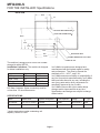
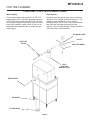
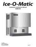
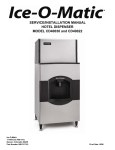
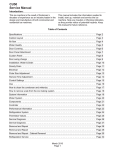
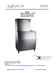
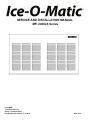
SERVICE AND INSTALLATION MANUAL
MFI 2406LS Series
Ice-O-Matic
11100 East 45th Ave
Denver, Colorado 80239
Part Number 9081358-02 17-3168-02
Date 10/08
SERVICE PARTS MANUAL
22 INCH WIDE ICE SERIES CUBERS
MODEL-ICE0320, ICE0520
Includes 50Hz. Units
ICE-O-Matic
11100 East 45th Ave
Denver, Colorado 80239
Part Number 9081297-01
PD04/02
Rev1/05
MFI2406LS
TO THE OWNER OR USER:
The service manual you are reading is intended to
provide you, and the maintenance or service
technician, with the information needed to install,
start up, clean, maintain and service this ice
system.
The is the freezer portion of a commercial ice
machine. It is designed to be connected to the
condensing section of a refrigeration system,
specifically a supermarket system.
Table of Contents
FOR THE INSTALLER: Specifications · · · · · · · · · · · · · · · · · · · · · · · · · · · · · · Page 2
FOR THE INSTALLER · · · · · · · · · · · · · · · · · · · · · · · · · · · · · · · · · · · · · · Page 3
FOR THE ELECTRICIAN · · · · · · · · · · · · · · · · · · · · · · · · · · · · · · · · · · · · · Page 4
FOR THE PLUMBER · · · · · · · · · · · · · · · · · · · · · · · · · · · · · · · · · · · · · · · Page 5
FOR THE INSTALLER: Final Check List · · · · · · · · · · · · · · · · · · · · · · · · · · · · · Page 6
INITIAL START UP · · · · · · · · · · · · · · · · · · · · · · · · · · · · · · · · · · · · · · · · Page 7
COMPONENT IDENTIFICATION
· · · · · · · · · · · · · · · · · · · · · · · · · · · · · · · · Page 8
COMPONENT DESCRIPTION: Evaporator · · · · · · · · · · · · · · · · · · · · · · · · · · · Page 9
CONTROL BOX: Components · · · · · · · · · · · · · · · · · · · · · · · · · · · · · · · · · · Page 10
ELECTRICAL SEQUENCE · · · · · · · · · · · · · · · · · · · · · · · · · · · · · · · · · · · · Page 11
OPERATION · · · · · · · · · · · · · · · · · · · · · · · · · · · · · · · · · · · · · · · · · · · Page 12
OPERATION: Refrigeration
· · · · · · · · · · · · · · · · · · · · · · · · · · · · · · · · · · · Page 13
CLEANING and SANITATION · · · · · · · · · · · · · · · · · · · · · · · · · · · · · · · · · · Page 14
SENSOR MAINTENANCE · · · · · · · · · · · · · · · · · · · · · · · · · · · · · · · · · · · · Page 15
BEARING MAINTENANCE · · · · · · · · · · · · · · · · · · · · · · · · · · · · · · · · · · · · Page 16
AUGER MAINTENANCE · · · · · · · · · · · · · · · · · · · · · · · · · · · · · · · · · · · · · Page 17
SERVICE DIAGNOSIS · · · · · · · · · · · · · · · · · · · · · · · · · · · · · · · · · · · · · · Page 18
SERVICE DIAGNOSIS · · · · · · · · · · · · · · · · · · · · · · · · · · · · · · · · · · · · · · Page 19
CONTROL SYSTEM DIAGNOSTICS
· · · · · · · · · · · · · · · · · · · · · · · · · · · · · · Page 20
REMOVAL AND REPLACEMENT · · · · · · · · · · · · · · · · · · · · · · · · · · · · · · · · Page 21
REMOVAL AND REPLACEMENT: Bearing And Breaker · · · · · · · · · · · · · · · · · · · · Page 22
REMOVAL AND REPLACEMENT · · · · · · · · · · · · · · · · · · · · · · · · · · · · · · · · Page 23
REMOVAL AND REPLACEMENT · · · · · · · · · · · · · · · · · · · · · · · · · · · · · · · · Page 24
REMOVAL AND REPLACEMENT: Evaporator · · · · · · · · · · · · · · · · · · · · · · · · · · Page 25
REMOVAL AND REPLACEMENT: Gearmotor · · · · · · · · · · · · · · · · · · · · · · · · · · Page 26
WIRING DIAGRAM · · · · · · · · · · · · · · · · · · · · · · · · · · · · · · · · · · · · · · · · Page 27
This manual was printed on recycled paper, keep it
for future reference.
Note the Warning symbol where it appears. It
marks a potential hazard.
Page 1
MFI2406LS
FOR THE INSTALLER: Specifications
BACK VIEW
15.53"
3.1"
SUCTION LINE CONNECTION 7 8"
LIQUID LINE CONNECTION 12"
20.84"
9.43"
5.25"
3"
17.8"
18.8"
ELECTRICAL INLET
21.66"
POTABLE WATER INLET 3/8" FLARE
DRAIN 3/4" FPT
The machine is designed to fit a B100 Ice-O-Matic
storage bin with a KBT-26.
Installation Limitations: The machine is designed
for indoor installations only.
Minimum
50oF
40oF
198 VAC
20 psi
Air Temp
Water Temp
Voltage
Water Pressure
Maximum
100oF
100oF
253 VAC
80 psi
RO Water Limitation: Water conductivity must be
no less than 35 microSiemens/cm.
Ice-O-Matic ice machines are designed and
manufactured with the highest regard for safety
and performance. They meet or exceed the
standards of U.L., N.S.F., and C.U.L.
Ice-O-Matic assumes no liability or responsibility of
any kind for products manufactured by Ice-O-Matic
that have been altered in any way, including the
use of any parts and/or other components not
specifically approved by Ice-O-matic.
Ice-O-Matic reserves the right to make design
changes and/or improvements at any time.
Specifications and designs are subject to change
without notice.
SPECIFICATIONS:
Model
Cabinet Size
System Refrigerant
BTUH required*
Voltage
MFI2406RL
42"w x 27"h x 24"d
R-404A
12,000
208-230/60/1 Flake
*Used to determine needed condensing unit
capacity. Not an AC load
Page 2
Ice Type
MFI2406LS
FOR THE INSTALLER
Select the Location:
The unit can only be installed indoors within the
limitations described on page 2.
The ice machine will have to be connected to the
building’s R-404A refrigeration system, check to be
sure that the system has AT LEAST enough extra
capacity to handle the BTUs (from table on page 2)
per hour @ 1100F. liquid line temperature (assume
a 00F. evaporator temperature).
Refrigeration Installation:
The skills of a refrigeration technician are required
to connect the ice machine to the building’s
refrigeration system.
Notes:
· Suction Line and Liquid Line Stubs are at the
back of the cabinet.
· R-404A models: 1.5 ounces of R-404A
refrigerant is in the system as a holding charge.
· Be sure there is enough BTU capacity.
· Be sure the liquid connection is NOT in series
Storage Bin:
Ice-O-Matic’s B100 will be the presumed bin of
choice. Install the legs and place the bin into
position.
A KBT26 bin adapter kit is required, follow
installation instructions included in the kit.
with another liquid line valve.
· Local Codes must be observed.
· A P-trap should be installed where there will be
more than 10’ of vertical rise in the suction line.
The ice machine is heavy, so the use of a
mechanical lift is recommended for lifting the
machine high enough to install on top of the bin.
Level the assembly by turning the leg levelers in
or out.
Locate the Nameplate: The nameplate is located
on the back panel of the machine, and contains the
electrical characteristics particular to the unit being
installed.
Page 3
MFI2406LS
FOR THE ELECTRICIAN
CONFORM TO ALL APPLICABLE CODES
Electrical Connections:
Locate the nameplate for the current
requirements, and then determine the
wire size and type per the National
Electric Code. The machine requires a
solid chassis to earth ground wire.
Refer to the wiring diagram. The ice
machine should be connected to it’s
own electrical circuit, and be
individually fused.
Voltage, when the unit is under full
load, must remain within the limitations
listed on page 2.
LOW VOLTAGE CAN CAUSE
EQUIPMENT MALFUNCTION AND/OR
DAMAGE
All external wiring should conform to
the National, State, and local electrical
codes. Usually the services of a
licensed electrician will be required.
DETAIL OF
JUNCTION BOX
JUNCTION
BOX
POWER SUPPLY
Page 4
MFI2406LS
FOR THE PLUMBER
CONFORM TO ALL APPLICABLE CODES
Water Supply:
The recommended water supply line is 3/8" O.D.
copper tubing, with a minimum operation pressure
of 20 PSIG, and a maximum of 80 PSIG. Connect
to cold water using the male flare connection at the
back of the machine. Install a shut off valve in an
accessible space between the ice maker and the
water supply.
Drain System:
All drains are of the gravity type, and must have a
minimum of 1/4" fall per foot of horizontal run. The
drains must be installed to conform to local
plumbing codes. The use of a vent at the machine
and at the bin will allow the system to drain
properly. Use only rigid tubing for drains; insulation
of the bin drain is recommended.
3/8" MALE FLARE
3/4" FPT
SHUT OFF
VALVE
VENT THIS DRAIN
FIELD
SUPPLIED
WATER FILTER
WATER INLET
BIN DRAIN
FLOOR DRAIN
Page 5
MFI2406LS
FOR THE INSTALLER: Final Check List
1. Is the unit installed where the air and water
temperatures are within and will remain within the
limitations for the unit?
2. Is there 6" clearance at the rear of the machine
for utility connections?
3. Has the water supply line be checked for
pressures between 20 and 80?
4. Has the unit been leveled?
5. Has the shipping material been removed from
inside the cabinet?
6. Have the electrical connections been made?
7. Have the drains been installed and checked for
leaks?
8. Has the refrigeration supply been installed and
checked for leaks?
9. Has the bin and cabinet been wiped clean or
sanitized?
10. Has the warranty registration card been
properly filled out and mailed to Ice-O-Matic?
11. Has the owner been given the service manual
and been instructed on how to maintain the ice
maker?
13. Has the owner been given the name and
telephone number of the local Ice-O-Matic service
agency?
Page 6
MFI2406LS
INITIAL START UP
1. Remove the top and front panels.
7. Switch on the other master (mode) switch,
observe that:
3. Switch on the electrical power.
· The liquid line valve opens
· The gearmotor runs
· Within a short time, that side of the machine
4. Open the hand valves (in the liquid lines).
· Water flows from the water reservoir, and the
2. Open the water valve, and observe that the two
float reservoirs fill up with water and shut off.
begins to make ice.
float drops, letting in more water.
5. Open the ball valves (in the suction lines).
6. Switch on one master (mode) switch, and
observe:
· That liquid line valve opens
· The gearmotor runs
· Within a short time, that side of the machine
begins to make ice.
· Water flows from the water reservoir, and the
8. With both sides operating, the sight glass should
remain full, and the low side pressure will be about
36 PSIG, + or - 2
Gearmotor amp draw should not exceed the
nameplate rating.
9. Check the system very carefully for any
refrigerant leaks, repair as needed.
float drops, letting in more water.
Page 7
MFI2406LS
COMPONENT IDENTIFICATION
Liquid line valve(s)
These valves operate to turn the ice making
process on and off.
When the ice level drops in the ice chute, the ice
level sensor will cause the circuit board to close
the liquid line relay, which energizes the liquid line
valve for that side of the system. The liquid line
valve opens, and liquid refrigerant flows to the
thermostatic expansion valve.
Thermostatic Expansion Valve
The metering device of each system, the valve(s)
sense the temperature of the suction line and vary
the amount of liquid refrigerant that passes through
the valve into the evaporator, thus maintaining a
constant level of refrigeration. TXV’s are factory
set. Do not adjust unnecessarily.
DO NOT ADJUST THE TXV UNTIL THE EPR HAS
BEEN SET.
The superheat setting is 4-80F. Measure the
temperature of the evaporator outlet at the TXV
bulb, and check the low side pressure at the EPR
valve. Convert the pressure to temperature (using
a temperature pressure chart) and subtract the
amount from the outlet temperature. The result is
the superheat. Use an electronic thermometer.
EPR: Evaporator Pressure Regulator Valve
This valve maintains a constant pressure on its
inlet (evaporators) side regardless of the pressure
on the outlet (suction) side. The EPR is factory set,
adjust only if needed. After adjusting, re-check
TXV superheat.
EPR Settings:
· R-404A models: 36 PSIG
Evaporators:
Where the water is frozen into ice crystals. As the
water cools, it begins to turn into ice, and the
slowly turning auger lifts the ice, as it is being
made, and forces it up and out of the “breaker” or
spout where the extra water is compressed out of
the ice. The ice then drops through the chute, into
the storage bin.
EPR VALVE
THERMO VALVE
LIQUID LINE
VALVE
THERMO
VALVE
EVAPORATOR
Page 8
MFI2406LS
COMPONENT DESCRIPTION: Evaporator
Evaporator: A refrigerated vertical tube filled
water and containing a water seal and auger.
Auger: A solid stainless steel double spiral auger,
it pushes the ice crystals up to the top of the
evaporator.
Water Seal: A two part “face” seal, the top half
rotating with the auger, the bottom half stationary,
the sealing action being where the two seal “faces”
meet.
Ice Sweep: A plastic cap with “fingers”. It revolves
with the auger to “sweep” the ice into the ice chute.
Divider: Where the ice is compressed and
much of the extra water is squeezed out of it
before it is discharged into the bin.
Motor: A split phase motor that drives the gear
reducer.
Bearing: As the ice is pushed up the evaporator,
the auger is thrust down, and pressure from the
auger thrust is taken up by this bearing.
ICE SWEEP
BEARING
DIVIDER
EVAPORATOR
AUGER
WATER
SEAL
MOTOR
Page 9
MFI2406LS
CONTROL BOX: Components
Circuit Board: Controlling the ice machine using
input from ice and water sensors. The board
switches loads on and off through relays. The
relays are for the gear motor (with a built in time
delay to clear the evaporator of ice when the unit
turns off) and for the liquid line valve. See photo
below.
On/Off (Mode) Switch: Manual control for that
side of the machine.
Control Board
Water OK Light
Power Light
Service Light
Freeze Light
Bin Full
Light
LED1
Compressor
Relay
LED3
Auger
Relay
Page 10
MFI2406LS
ELECTRICAL SEQUENCE
There are 7 indicator lights on the control board:
Shut Down:
· WTR-OK (Water OK). Green. Normal =
Glowing. Glows when there is water in the
reservoir.
· PWR-OK (Power OK). Green. Normal =
Glowing. Glows when the control board has
power and is functional.
· The compressor relay opens, LED1 goes out.
· The liquid line valve closes.
· The refrigerant flow stops.
· The auger motor stays on for 1 more minute,
clearing out ice in the evaporator, and then
· The auger motor relay opens, LED3 goes out
· Service. Red. Normally Off.
· Freeze. Red. Normally glowing when making
ice.
· Bin Full. Red. Normally Off when making ice.
· LED1. White. Located next to the board’s
Compressor Relay (used to power the liquid line
valve). Normally Glowing when making ice.
· LED3. White. Located next to the board’s Auger
Motor Relay. Normally Glowing when making
ice.
If the machine is switched off at the mode switch,
but is otherwise ready to go, switching the mode
switch to ON does the following:
and the auger motor stops.
The liquid line valve will not re-open until 2 minutes
or more have passed after the last shut down.
If the path between the ice level sensors remains
clear for more than 10 seconds the ice machine
will restart.
Control Board Protection Devices
· When the water level in the reservoir falls
below the water level sensor’s tip, the WTR-OK
light goes out and the machine shuts down.
When water refills the reservoir the WTR-OK
light glows and the machine starts up again.
· If the auger drive motor current becomes
· The PWR-OK light glows.
· If there is water in the reservoir the WTR-OK
light glows.
· After 10 seconds the Freeze, LED1 and LED3
lights glow and the machine starts up.
Start Up:
· The compressor relay and auger motor relay
become energized, connecting power to the
windings of the auger motor and liquid line valve
coil.
· The liquid line valve opens, refrigerant flows to
the expansion valve and ice making begins.
· As ice is made it passes between the ice level
sensors but because it is not a continuous
stream it only interrupts the sensor’s infrared
beam momentarily. The bin full light remains off
and the machine stays on until ice builds up in
the bin and blocks the path between the
sensors for 6 seconds or longer. When that
occurs the bin full light glows and the machine
shuts down.
excessive the compressor and auger drive
motor will be switched Off and the Service light
will blink. The control board will restart the
auger drive motor in 4 minutes. If during the first
60 seconds after restart the auger motor current
stays within limits, the liquid line valve is
reopened and the machine returns to normal
operation. If the auger motor’s current is
excessive within 60 seconds after the restart,
the process will be repeated once more. If
during that try the current is still excessive the
machine shuts down and must be manually
reset. The service light will then be glowing
continuously.
To Reset: Disconnect and reconnect electrical
power to the unit.
The mode (on - off) switch is the manual control
for the complete machine, but it is not a service
disconnect.
Page 11
MFI2406LS
OPERATION
Water
Water enters the machine through the 3/8" male
flare at the rear of the cabinet, goes to the water
reservoir which it enters through the float valve.
The water then goes out the bottom of the
reservoir tank to the bottom of the evaporator.
Reservoir overflow or evaporator condensation is
routed to the drain.
WATER
INLET
RESERVOIR
ICE CHUTE
WATER LEVEL
EVAPORATOR
WATER INLET
WATER SCHEMATIC
DRIP PAN DRAIN
Page 12
MFI2406LS
OPERATION: Refrigeration
The remote high side supplies high pressure liquid
refrigerant to the liquid line connection on the ice
machine. After the sight glass, there are two
separate liquid lines, each leading to a liquid line
valve. When the individual ice level sensor causes
the circuit board to energize the liquid line valve,
the valve opens, allowing the liquid refrigerant to
enter that expansion valve. The thermostatic
expansion valve meters the liquid refrigerant into
the evaporator, where it
boils off (evaporates) and
absorbs heat. It then
moves through the ball
valve and into the
evaporator pressure
regulator valve, or EPR.
The EPR keeps the
evaporator pressure
above a predetermined
point, even though the
suction line pressure of
the remote high side
HAND VALVE
system may vary. The
refrigerant, now a low
LIQUID LINE
pressure gas, moves into
VALVE
the suction line of the
remote high side system.
LIQUID
LINE
SIGHT GLASS
THERMO VALVE
EVAPORATORS
BALL VALVES
SUCTION LINE
EPR VALVE
Page 13
MFI2406LS
CLEANING and SANITATION
An Ice-O-Matic ice system represents a sizable investment of time and money in any company’s business.
In order to receive the best return for that investment, it MUST receive periodic maintenance.
It is the USER’S RESPONSIBILITY to see that the unit is properly maintained. It is always preferable, and
less costly in the long run, to avoid possible down time by keeping it clean; adjusting it as needed; and by
replacing worn parts before they can cause failure. The following is a list of recommended maintenance
that will help keep the machine running with a minimum of problems.
Maintenance and Cleaning should be scheduled at a minimum of twice per year.
ICEMAKING SYSTEM: In place cleaning
1. Check and clean any water treatment devices,
if any are installed.
2. Pull out and remove the front panel.
3. Move the ON-OFF switch to OFF.
4. Remove all the ice from the storage bin.
5. Remove the cover to the water reservoir and
block the float up.
6. Drain the water reservoir and freezer assembly
using the drain tube attached to the freezer water
inlet. Return the drain tube to its normal upright
position and replace the end cap.
7. Prepare the cleaning solution: Mix eight
ounces of ice machine cleaner with three quarts of
hot water. The water should be between 90-115
degrees F.
Ice Machine Cleaner
contains acids. These
compounds may cause
burns.
If swallowed, DO NOT
induce vomiting. Give large
amounts of water or milk.
Call Physician
immediately. In case of
external contact, flush with
water.
Keep out of the reach of
children.
8. Slowly pour the cleaning solution into the water
reservoir until it is full. Wait 15 minutes, then
switch the master switch to ON.
9. As the ice maker begins to use water from the
reservoir, continue to add more cleaning solution
to maintain a full reservoir.
10. After all of the cleaning solution has been
added to the reservoir, and the reservoir is nearly
empty, switch the master switch to OFF.
11. After draining the reservoir, as in step 6, wash
and rinse the water reservoir.
12. Go thru steps 13-19 to sanitize the ice machine
water system.
13. Mix two gallons of sanitizer solution. Use an
approved sanitizer.
A possible sanitizer solution may be obtained by
mixing two gallons of warm (90-115oF.) potable
water with 1 ounce of household bleach.
14. Slowly pout the sanitizer solution into the water
reservoir until the float rises, then switch the
master switch ON.
15. As the ice machine uses water from the
reservoir, continue to pour the sanitizer solution
into the reservoir.
16. After 12 of the sanitizer solution has been
added to the reservoir, and the reservoir is nearly
empty, switch the master switch OFF.
17. Drain the reservoir and thoroughly wash the
interior of the reservoir and cover with sanitizer
solution. Be sure the drain hose is upright and
capped.
18. Remove the block from the float in the water
reservoir.
19. Switch the master switch to ON
20. Continue ice making for at least 15 minutes, to
flush out any cleaning solution.
DO NOT USE any ice produced from the
cleaning solution. Be sure no ice remains in
the bin.
21. Remove all ice from the storage bin.
22. Add warm water to the ice storage bin and
thoroughly wash and rinse all surfaces within the
bin.
23. Sanitize the bin interior by washing the interior
of the bin with the balance of the sanitizer solution.
24. Switch the master switch ON.
Page 14
MFI2406LS
SENSOR MAINTENANCE
1. The bin control uses devices that sense light,
therefore they must be kept clean enough so that
they can “see”. At least twice a year, remove the
bin control sensors from the base of the ice chute,
and wipe the inside clean, as illustrated.
2. The ice machine senses water level by a probe
located in the water reservoir. At least twice a year,
the probe should be removed from the reservoir,
and the tip wiped clean of mineral build-up.
SLIDE ICE LEVEL
CONTROLS OUT
OF CHUTE
CLEAN THE ICE
LEVEL CONTROL
SENSORS
Clean the Probe's Tip with ice
machine cleaner and a clean,
soft cloth.
Page 15
MFI2406LS
BEARING MAINTENANCE
· unscrewing the auger stud
The top bearing in the breaker should also be
checked at least two times per year.
Check the breaker bearing by:
Auger Stud
· removing the ice chute cover
Chute Cover
Cap Screw
· unscrewing the ice sweep
Ice Sweep
Inspect the bearing. There should be plenty of
grease in sight. If grease is needed the bearing
and breaker should be removed to check the
action of the bearing. It should rotate smoothly.
To remove the breaker take out all four allen head
cap screws and pull the breaker off the auger and
evaporator.
If the bearing only needs grease, inject grease into
the bearingusing a grease needle. Be sure to inject
grease evenly and thoroughly.
See Removal and Replacement section to replace
bearing or seals.
Reverse to reassemble.
Grease
Needle
· removing the water shed and the breaker cover
(left hand thread)
Breaker Cover
Off
Page 16
MFI2406LS
AUGER MAINTENANCE
In some installations the water supply to the ice
maker will be so concentrated with dissolved
minerals, (such as calcium carbonate) that as ice
is made, the evaporator and auger become coated
with those minerals, requiring a more frequent
cleaning than twice per year. If in doubt about the
condition of the evaporator and auger, the auger
can be removed so the parts can be inspected.
Note: Water filters can filter out suspended solids,
but not dissolved solids. “Soft” water may not be
the complete answer. Check with a water
treatment specialist regarding water treatment.
Note:
Flaker Components Shown, Nugget
Components are Similar
DIVIDER, AUGER
AND SLOTTED
COLLAR
ALLEN HEAD
SCREWS
Switch off electrical power, and shut off the water
supply.
For more information on removal of these parts,
see REMOVAL AND REPLACEMENT.
1. To remove the auger, remove front and top
panel. See Removal And Replacement.
2. Push bail clamp back and remove ice chute
cover.
3. Unscrew and remove ice sweep.
4. Remove ice chute from evaporator.
5. Remove 4 allen head screws holding breaker to
evaporator.
6. Pull up on breaker to remove auger.
Allow the auger to dry, the stainless steel of the
auger and evaporator must be clean and bright.
Clean the auger and evaporator as required. DO
NOT HONE THE EVAPORATOR.
7. Replace the water seal.
8. Reverse to reassemble.
BREAKER
COVER
Page 17
MFI2406LS
SERVICE DIAGNOSIS
Symptom
No ice is made, nothing
operates
Possible Cause
Unit off due to no power.
Unit off due to master switch in Off position
Unit off due to low water level in reservoir
Unit off due to ice level sensors
(photo-electric eyes) blocked
Unit off due to scale on water level sensor
Auger motor hums but does not turn
No ice, auger motor is
turning
Unit makes ice, but very
slowly
Probable Correction
Restore power
Move master switch to ON
Check water supply, filter and
float valve.
Check/clean ice level sensors
Clean water level sensor
Auger can’t turn. Circuit board
has not yet shut unit down.
Auger turning but there is no refrigeration
Liquid line valve not opening,
effect
check coil, check board relay.
No refrigerant to ice machine,
check main system.
Unit is shut down
Circuit board has shut ice
machine down due to high auger
motor amp draw. Check for
cause of high amp draw,
including bearings, gear motor
condition and scale on auger &
evaporator. May also be due to
liquid line valve leak thru during
the off cycle. Check valve.
Auger not turning
Due to: motor failure; auger relay
failure on circuit board; or gears
stripped. Check drive train.
Low suction pressure
Liquid line valve not opening due
to coil failure or failure of
compressor relay on circuit board
EPR setting too low, check/adjust
TXV restricted or not metering.
Check bulb temperature.
No power to circuit board
Check harness
Circuit board gear motor relay will not close Check / replace board
Water level or ice level sensor failed
Check / replace sensor
Liquid line valve coil is open
Check / replace valve coil
Circuit board relay will not close
Check / replace board
High discharge pressure because of dirty
Clean condenser.
condenser
Auger and evaporator are coated with
Clean the water system
minerals
Low suction pressure due to low EPR
Adjust EPR, check TXV
setting
superheat
Page 18
MFI2406LS
SERVICE DIAGNOSIS
Symptom
Possible Cause
Probable Correction
Water Leak
Drain plugged up
Clean out drain
Tubing cracked
Replace tubing
Condensation on drain tubing
Insulate tubing
Hose off
Reattach hose
Reservoir cover off
Return cover to reservoir
Reservoir cracked
Replace reservoir
Evaporator water seal leaks
Check base of evaporator & drip
pan. If the seal leaks, shut off the
water, remove the auger, replace
the water seal. Check gear motor
for water infiltration.
Uses too much water
Reservoir float valve leaks thru
Replace float valve or seat
Excessive ice meltage
Bin drain clogged
Clean out bin drain.
Improper installation of drains,
they are connected.
Drains must be separate.
Poor fit between bin door and
door frame
Adjust or replace
Evaporator coated internally with
minerals
Clean with Ice Machine Cleaner
Motor bearings dry
Oil or replace motor
Machine makes too much noise
Page 19
MFI2406LS
CONTROL SYSTEM DIAGNOSTICS
The control system consists of:
· Control Board
· Water Sensor
· Ice Sensors
If the unit is OFF, check the control board:
1. Is the Power OK light on? If not check power to
the unit. If it has power, and the Power OK light is
NOT on, check the high pressure and low pressure
cut outs. If they are both closed, replace the board.
If the Power OK light is ON, go to the next step.
2. Is the Water OK light on? If it is, go to the next
step. If not, check the water level in the reservoir. If
there is water in the reservoir, check that the water
sensor is plugged in. To check the water sensor:
A. Unplug water sensor.
B. Pull water sensor from reservoir.
C. Place one ohmmeter lead on the sensor's plug
and the other on the sensor's tip. The meter should
show nearly zero resistance. If it reads infinite
resistance, check the tip for corrosion. If it is clean
and still reads open, replace the sensor.
OR connect a copper wire to the wire where the
water sensor plugs into and place the other end in
the water. The water OK light should go ON. If it
does not, replace the control board.
3. Ice sensor check. Is the Bin Full light Off? If it is
OFF and the Service light is Off, and the unit is not
running, replace the control board.
If it is OFF and the auger motor is running but the
compressor is not, check the compressor contactor
coil.
If it is on, the ice sensors may be blocked. Remove
them and check for mineral scale. Scotsman's test
box can also be used to determine if the ice sensors
or board are defective.
Using the tester:
A. Disconnect the ice sensors at the connection by
the ice chute. Connect the LED and PHOTO TRANS
wires to the control board's wires.
B. With the On - Off (mode) switch in either position,
move the Bin Full switch on the tester to Bin Full the tester's light will blink and after a few seconds
the bin full light on the control board will come on. If
not, replace the board.
Move the Bin switch on the tester to Bin Empty. The
light on the tester will go out, and after a few
seconds the Bin Full light on the board will go out. If
master switch is ON, the unit should start.
Page 20
MFI2406LS
REMOVAL AND REPLACEMENT
WATER RESERVOIR
1. Shut off the water supply to the ice maker.
2. Remove front panel and reservoir cover.
3. To remove float only, disconnect water inlet
tube, push in the tab behind the reservoir and pull
valve assembly out of the reservoir tank.
4. To remove reservoir, disconnect water inlet
compression fitting at reservoir inlet.
5. Remove drain hose from reservoir.
6. Remove evaporator inlet hose from reservoir.
7. Remove mounting screws from reservoir
bracket, and remove reservoir from ice maker.
8. Reverse to reassemble.
BIN CONTROLS (Ice Level Sensors)
1. Disconnect electrical power.
2. Remove front panel.
3. Remove control box cover.
4. Locate ice chute, at the base of the chute, in
front of and behind it are two plastic bin control
mounts.
5. Slide each bin control to the left, and in the
control box, disconnect the electrical leads
connecting the bin control to the circuit board.
6. Reverse to reassemble, be certain that the bin
controls are aligned so that the ice level sensors
are visible (centered) through the holes in the cube
chute.
SLIDE BIN
CONTROLS
IN AND OUT
Page 21
MFI2406LS
REMOVAL AND REPLACEMENT: Bearing And Breaker
Note: Removal of the auger, water seal,
evaporator and gearmotor must begin at the top of
the assembly.
To Remove the Breaker Bearing Assembly:
Electrical Shock Hazard
Electrical shock can cause
personal injury. Disconnect
electrical power before
beginning.
1. Remove panels and disconnect electrical power.
2. Push back bail clamp, remove insulation
retaining strap and insulation, remove ice chute
cover.
3. Unscrew and remove ice sweep.
4. Lift up and remove ice chute.
5. The breaker may be removed from the auger
and evaporator without disturbing the auger.
a. Unscrew breaker cover from breaker (left hand
threads)
b. Unscrew auger stud from top of auger.
c. Unscrew 4 allen head cap screws holding
breaker to evaporator.
Step 5- a
d. Lift up, and remove breaker/bearing assembly
from auger & evaporator.
6. Service the bearing. Check for rust, rough spots
and damage.
a. The bearing is pressed into the breaker, to
remove the bearing and replace it an arbor press is
needed.
b. Replace lower seals before installing new
bearing in breaker.
Note: seals must be pressed in with a tool pushing
against the outer edge only, they will not install by
hand.
Replace parts as required. Re-grease bearing with
Ice-O-Matic part no. 6051062-01 bearing grease.
Replace top seal, and check the o-rings, replace if
cut or torn.
7. Reverse to reassemble: specific tools and
materials are required to install properly.
a. Add food grade grease such as Ice-O-Matic part
number 6051036-01 to the seal area before
installing on the auger.
b. Check the seal to shaft areas for cuts, or rough
spots: none are permitted.
Step 5-b
Step 5-c and Step 6
BEARING
ICE SWEEP
SEALS
SLOTTED
COLLAR
AUGER
STUD
BREAKER
COVER
DIVIDER
Page 22
MFI2406LS
REMOVAL AND REPLACEMENT
To Remove the Auger:
Turn off the water to the machine, and unclip the
evaporator drain hose, pull it down and drain the
evaporator into the bin or a container.
Moving Parts Hazard
Moving parts can cause
personal injury. Disconnect
electrical power before
beginning.
1. The top panel must be removed.
2. Remove ice chute cover.
3. Unscrew ice sweep.
4. Remove ice chute body.
5. The auger and breaker/bearing may now be
removed as an assembly.
a. Unscrew 4 allen head cap screws holding
breaker to evaporator.
b. Lift up on breaker and remove auger from
evaporator.
e. If the auger is stuck use a slide hammer type
puller to pull on the auger at the threaded hole.
The size of that hole is 5/8"-18.
Inspect the auger, the critical areas of the auger
are:
1. The auger body. It should be clean and
shining. Sometimes an auger will appear clean
when wet, but after it is dry it will be seen to be
stained. Scrub the auger with ice machine cleaner
and hot water.
Ice machine cleaner is an acid. Handle it with
extreme care, keep out of the reach of children.
2. The water seal area. Because the auger has
been removed, the water seal will have to be
replaced. Remove the water seal top half from the
auger, and inspect the auger for minerals clean as
required.
SLIDE
HAMMER
PULLER
DIVIDER
AND AUGER
ASSEMBLY
Note: If the auger is stuck, the breaker must be
removed from the auger.
The breaker may be removed from the auger and
evaporator without disturbing the auger.
a. Use spanner wrench and unscrew breaker
cover from breaker (left hand threads)
b. Unscrew auger stud from top of auger.
c. Unscrew 4 allen head cap screws holding
breaker to evaporator.
d. Lift up and remove breaker from evaporator.
Page 23
MFI2406LS
REMOVAL AND REPLACEMENT
Moving Parts Hazard.
Moving parts can cause
personal injury. Disconnect
electrical power before
beginning.
To Remove the Water Seal:
(Assuming all steps to remove the auger have
been performed.)
1. The gearmotor/evaporator assembly will have to
be exposed.
2. Remove the 4 hex head cap screws holding the
evaporator to the gearmotor assembly. Lift the
evaporator up and off of the gearmotor.
3. Remove the snap ring or wire retainer from the
grove under the water seal.
4. Pull or drive out the lower half of the water seal.
To Replace the Water Seal:
1. Lubricate the water seal with water, and push
the water seal into the bottom of the evaporator
slightly past the grove for the snap ring.
2. Replace the snap ring and pull the water seal
down against it.
3. The part of the water seal that rotates with the
auger must also be replaced. Remove the old part
from the auger and clean the mounting area.
4. Place a small bead of food grade silastic sealant
(such as 732 RTV ) on the area of the auger where
the water seal is to be mounted.
5. Carefully push the water seal (rubber side
against the auger shoulder and the silastic.)
CAUTION
Do not get any silastic onto the face of the seal.
6. Allow the auger and seal to air dry until the
silastic is dry on the surface.
7. If the original water seal was leaking, it would be
a good idea to inspect the interior of the
gearmotor.
WATER
SEAL
RETAINING
RING
PLACE FOOD
GRADE SEALANT
HERE
Page 24
MFI2406LS
REMOVAL AND REPLACEMENT: Evaporator
To Replace the Evaporator:
(Assuming all the steps for removal of the thrust
bearing, breaker, auger, and water seal have been
performed.)
1. Shut the hand valves in the liquid and suction
lines to the evaporator being serviced; then
discharge the refrigerant.
2. Unsweat the refrigerant connections:
a) At the thermostatic expansion valve outlet.
CAUTION
To Reassemble the Evaporator and Auger
1. After the gearmotor has been inspected, fasten
the evaporator to the gear motor, torque the bolts
to 110 inch pounds.
2. Lower the auger into the evaporator barrel,
slightly turning it to match up with the drive end. Do
Not Drop Into the Evaporator.
3. Complete the reassembly by reversing the
disassembly for the breaker & thrust bearing
assembly.
Heat sink the TXV body when unsweating or
resweating the adjacent tubing.
b) At the suction line at the joint about 3" from the
evaporator.
3. Remove the evaporator.
4. Unsweat the drier from the liquid line.
5. After installing a new water seal in the new
evaporator (see “To Replace the Water Seal”)
sweat in the new evaporator at the old
connections.
6. Install an new drier in the liquid line.
7. Evacuate the system until dehydrated, then
weigh in the nameplate charge. Check for leaks.
8. Install auger, breaker, breaker bearing
assembly, and ice discharge chute in reverse order
of disassembly. See “To Reassemble Evaporator
and Auger”
ICE SWEEP
AUGER
EVAP
BEARING
DR
DIVIDER/BREAKER
Page 25
MFI2406LS
REMOVAL AND REPLACEMENT: Gearmotor
To Remove and Repair the Gearmotor
Assembly:
(Assuming that the procedures through removal of
the water seal have been performed.)
1. Remove the electrical wires from the gear drive
motor.
2. Unscrew the 4 cap screws holding the
gearmotor to the gearmotor plate.
3. Remove the gearmotor from the ice maker.
To Inspect the gearmotor.
A) Remove the cap screws holding the gearmotor
case halves together and pry the two cases apart.
B) To lift off the cover, lift up until you can feel
internal contact, then pull the cover towards the
output gear end, and then
lift the cover (with drive
motor attached) up and
away from the gear motor
case.
Note: The case cover
output gear, bearings, and
shaft are one pressed
together assembly.
Replace as a unit.
C) Inspect the oil, gears,
GEARCASE
and bearings. If the oil
COVER
level and condition is
acceptable, quickly check
the gears and bearings.
They are likely to be fine if
the oil is.
If there is evidence of
water in the oil (rusty
bearings and gears; the oil
having a creamy white
appearance; oil level too
high) carefully inspect the
bearings and gears. If in
doubt about the condition
of a part, replace it. The oil
quantity is 14 fluid ounces,
do not overfill.
Note: The gears and
bearings are available only
as pressed together sets.
D) After replacing parts as required, (if any)
reassemble the gearcase. The two smaller gears
and the oil should be in the lower case, the output
gear will be with the cover. As you lower the cover
onto the lower case, cover will have to be moved
closer to the second gear after the output gear has
cleared the second gear top bearing.
E) After the case is together, and the locating pins
are secure in both ends, replace all cap screws.
4. Bench test the gearmotor, check for oil leaks,
noise, and amp draw.
MOTOR
SEAL
Page 26
BEARING
GASKET
MFI Series 2406LS
Wiring Diagram
Page 27
MFI Series
Service History
Service History
Model Number__________________Serial Number__________________Date Installed__________
__________________________________________________________________________________________
__________________________________________________________________________________________
__________________________________________________________________________________________
__________________________________________________________________________________________
__________________________________________________________________________________________
__________________________________________________________________________________________
__________________________________________________________________________________________
__________________________________________________________________________________________
__________________________________________________________________________________________
__________________________________________________________________________________________
__________________________________________________________________________________________
__________________________________________________________________________________________
__________________________________________________________________________________________
__________________________________________________________________________________________
__________________________________________________________________________________________
__________________________________________________________________________________________
__________________________________________________________________________________________
__________________________________________________________________________________________
__________________________________________________________________________________________
__________________________________________________________________________________________
__________________________________________________________________________________________
__________________________________________________________________________________________
__________________________________________________________________________________________
__________________________________________________________________________________________
__________________________________________________________________________________________
__________________________________________________________________________________________
__________________________________________________________________________________________
__________________________________________________________________________________________
__________________________________________________________________________________________
__________________________________________________________________________________________
__________________________________________________________________________________________
__________________________________________________________________________________________
__________________________________________________________________________________________
__________________________________________________________________________________________
__________________________________________________________________________________________
__________________________________________________________________________________________
__________________________________________________________________________________________
__________________________________________________________________________________________
__________________________________________________________________________________________
__________________________________________________________________________________________
__________________________________________________________________________________________
__________________________________________________________________________________________
__________________________________________________________________________________________
__________________________________________________________________________________________
__________________________________________________________________________________________
__________________________________________________________________________________________
__________________________________________________________________________________________
__________________________________________________________________________________________
__________________________________________________________________________________________
__________________________________________________________________________________________
__________________________________________________________________________________________
__________________________________________________________________________________________
Page 28