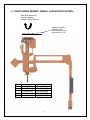
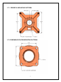
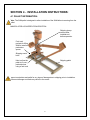
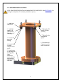
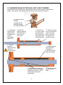
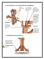
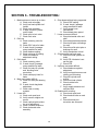
1
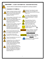
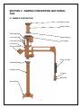
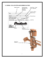
OPERATOR SERVICE MANUAL
SAM G
POSITECH CORPORATION
191 N RUSH LAKE ROAD
LAURENS, IA 50554
Phone Number: 800-831-6026
24 Hour Service Phone Number: 541-954-2948
Email: [email protected]
SERIAL NO: _________
RUN NO: _________
REV A
04APR14
191 N. Rush Lake Road, Laurens, Iowa 50554 | T. 712.841.4548 | F. 712.841.4765 | www.positech.com
NOTES:
………………………………………………………………………………………………………………………………………………………….
………………………………………………………………………………………………………………………………………………………….
………………………………………………………………………………………………………………………………………………………….
………………………………………………………………………………………………………………………………………………………….
………………………………………………………………………………………………………………………………………………………….
………………………………………………………………………………………………………………………………………………………….
………………………………………………………………………………………………………………………………………………………….
………………………………………………………………………………………………………………………………………………………….
………………………………………………………………………………………………………………………………………………………….
………………………………………………………………………………………………………………………………………………………….
………………………………………………………………………………………………………………………………………………………….
………………………………………………………………………………………………………………………………………………………….
………………………………………………………………………………………………………………………………………………………….
………………………………………………………………………………………………………………………………………………………….
………………………………………………………………………………………………………………………………………………………….
………………………………………………………………………………………………………………………………………………………….
………………………………………………………………………………………………………………………………………………………….
………………………………………………………………………………………………………………………………………………………….
………………………………………………………………………………………………………………………………………………………….
………………………………………………………………………………………………………………………………………………………….
………………………………………………………………………………………………………………………………………………………….
………………………………………………………………………………………………………………………………………………………….
………………………………………………………………………………………………………………………………………………………….
………………………………………………………………………………………………………………………………………………………….
………………………………………………………………………………………………………………………………………………………….
………………………………………………………………………………………………………………………………………………………….
………………………………………………………………………………………………………………………………………………………….
………………………………………………………………………………………………………………………………………………………….
………………………………………………………………………………………………………………………………………………………….
Table of Contents
SECTION 1 - SAFETY INFORMATION – READ BEFORE USING: ........... 2
1.1 MEANING OF SYMBOLS: ............................................................................................................ 2
1.2 DO’S AND DO NOT’S: ................................................................................................................... 1
1.3 SAFETY PRECAUTIONS: ............................................................................................................. 2
SECTION 2 - NAMING CONVENTION AND SERIAL TAG: ....................... 3
2.1 NAMING CONVENTION: ............................................................................................................... 3
2.2 SERIAL TAG LOCATION AND NOMENCLATURE: ....................................................................... 4
SECTION 3 - SPECIFICATIONS:................................................................. 5
3.1 MECHANICAL SPECIFICATIONS: ................................................................................................ 5
3.2 PNEUMATIC SPECIFICATIONS:................................................................................................... 5
3.3 HYDRAULIC SPECIFICATIONS: ................................................................................................... 5
3.4 ELECTRICAL SPECIFICATIONS:.................................................................................................. 5
3.5 AERIAL NOISE: ............................................................................................................................. 5
3.6 ENVIRONMENTAL CONDITIONS: ................................................................................................ 5
3.7 OVERTURNING MOMENT, WEIGHT, & MOUNTING PATTERN: .................................................. 6
3.7.1 PEDESTAL MOUNTING PATTERN: ....................................................................................... 7
3.7.2 OVERHEAD SPACER MOUNTING PATTERN ....................................................................... 7
3.8 CONCRETE MOUNTING GUIDELINES:........................................................................................ 8
3.8.1 SOIL CONDITION: .................................................................................................................. 8
3.8.2 FULLY REINFORCED CONCRETE FLOOR CONDITION: ...................................................... 8
3.8.3 POURED FOUNDATION CONDITION: ................................................................................... 8
3.8.4 PLATING ON CONCRETE: ..................................................................................................... 8
SECTION 4 - INSTALLATION INSTRUCTIONS: ........................................ 9
4.1 PALLET INFORMATION: ............................................................................................................... 9
4.2 PEDESTAL INSTALLATION: ....................................................................................................... 10
4.3 SPACER INSTALLATION: ........................................................................................................... 11
4.4 LIFTING WITH A FORK TRUCK WHEN STILL ON PALLET: ....................................................... 12
4.5 LIFTING WITH AN OVERHEAD CRANE: .................................................................................... 13
4.6 ATTACHING MANIPULATOR TO PEDESTAL: ............................................................................ 14
4.7 ATTACHING MANIPULATOR TO SPACER: ................................................................................ 14
4.8 DISASSEMBLING THE PALLET .................................................................................................. 15
4.9 INSTALLING TOOLING (U-FRAME) FROM FACTORY: ............................................................. 16
SECTION 5 - MAINTENANCE, ADJUSTMENTS, & INSPECTIONS: ...... 17
5.1 LUBRICATION SCHEDULE: ........................................................................................................ 19
5.2 ADJUSTING A DUAL LOST LOAD LOCK VALVE: ....................................................................... 20
5.2.1 UNLOCKING A LOCKED LOST LOAD CYLINDER: .............................................................. 20
5.2.2 CHECKING IF LOST LOAD WORKS PROPERLY: ............................................................... 20
5.2.3 ADJUSTING A LOST LOAD VALVE THAT IS TOO SENSITIVE: ........................................... 21
5.3 CHANGING SEALS IN THE DUAL LOST LOAD CYLINDER:....................................................... 22
5.4 REBUILDING A PISTON TYPE LIFT CYLINDER: ........................................................................ 23
5.5 ADJUSTING THE FORCE LINK ROLLER: ................................................................................... 24
5.6 ADJUSTING THE LIFT HOUSING ROLLER ASSEMBLIES: ........................................................ 25
5.7 TIGHTENING THE ACHOR BOLTS: ............................................................................................ 25
5.8 LEVELING THE PEDESTAL OR SPACER AFTER INSTALLATION:........................................... 26
5.9 AIR LINE SIZING FOR SUPPLY AIR ........................................................................................... 27
SECTION 6 - TROUBLESHOOTING: ........................................................ 28
SECTION 7 - DRAWINGS: ......................................................................... 29
SECTION 8 - RECOMMENDED SPARE PARTS: ..................................... 30
i
SECTION 1 - SAFETY INFORMATION – READ BEFORE USING:
Important: Read and understand these warnings before operating equipment!
1.1 MEANING OF SYMBOLS:
Hook point: Be sure hook is secure
before lifting. Do not lift people. Be
aware of tool sway that may occur when
using a hook.
Danger: Indicates a hazardous situation
which if not avoided, will result in death
or serious injury. Possible hazards are
shown in the adjoining symbols or
explained in the text.
Hot Surface: Surface temperature
can exceed greater than 70 deg. C
during normal operation. DO NOT
Touch!!
Electrical hazard: Contact with live parts
can result in immediate death.
Protective covers marked with this sign
may only be opened by qualified
personnel only. Disconnect the feed
voltage before opening.
Pressurized Source Caution.
Contents under Pressure. Do
not disconnect without turning
power off, locking out, and
supporting lowered lift arms
Suspended load overhead: Do not stop
or transit near suspended load. Use
extreme caution when moving
suspended loads; do not leave
suspended loads unattended. Do not
leave load suspended above people.
Emergency Stop: Stop device
activation removes power from all
machine functions.
Warning: Indicates a potentially
Hazardous situation, which if
not avoided could result in
death or serious injury.
Risk of crushing hands and/or feet:
Do not approach mechanical parts that
are moving or may start moving.
Do not handle the load while
standing in front of the terminal arm.
Caution: Indicates a potentially
hazardous situation, which if not
avoided may result in injury
Parts of the manipulator may come into
collision with the operator.
Hearing Protection: Recommended
near sources >= 80 dbA.
Clamping Device: Do not depress the
gripping control button unless the
correct load to be handled is between
the jaws. Keep body parts clear when
actuating clamping devices.
Pinch point: Indicates possible pinch
point. Keep extremities clear of moving
parts. Do not wear loose clothing or
jewelry near equipment. Avoid contact
with areas marked with this symbol or
PINCH POINT text.
2
1.2 DO’S AND DO NOT’S:
Perform the following Do’s and Do Not’s for safe operation of the manipulator. Following these guidelines
will increase operator awareness of his/her own safety and the safety of others. Frequent examinations
and periodic inspections of the equipment and conscientious observance of safety rules will help prevent
injuries, lost production time, and money.
To avoid injury: THE DO’S
DO read all warnings and safety information before operating unit.
DO become familiar with the operating controls, procedures and warnings.
DO make sure that if the manipulator is mounted on a portable base, the support surface is flat and
that the leveling jacks touch the floor.
DO maintain firm footing while operating the manipulator.
DO operate the manipulator arms by pushing and pulling directly in front of the body.
DO make sure that the load is free to move and will clear all obstructions.
DO make sure that all persons stay clear of the suspended load.
DO warn personnel of an approaching load.
DO promptly report any malfunction, unusual, performance, or damage to the manipulator.
DO inspect the manipulator regularly, replace any damaged or worn parts, and keep appropriate
records of maintenance.
DO replace damaged or missing labels.
DO use Positech parts when repairing the manipulator.
To avoid injury: THE DO NOT’S
DO NOT operate manipulator unless qualified to do so.
DO NOT modify or alter the manipulator, tooling, or valve settings.
DO NOT exceed the rated capacity for the manipulator or tooling.
DO NOT use a damaged unit or a unit that is not working correctly.
DO NOT allow your attention to be diverted while operating the manipulator.
DO NOT operate the manipulator by pushing or pulling that requires twisting the back.
DO NOT use the manipulator to lift, support, or transfer people.
DO NOT lift loads over people.
DO NOT lift loads higher than necessary.
DO NOT allow unauthorized personnel within the working area of the manipulator.
DO NOT leave a suspended load unattended unless safety precautions have been taken.
DO NOT remove or obscure any warning labels on the manipulator.
DO NOT adjust the manipulator unless qualified to perform such maintenance or repair.
DO NOT set or rest the manipulator on vacuum cups or grip jaws.
DO NOT operate equipment in an explosive or humid environment without optional protective
features offered and supplied with equipment.
1
1.3 SAFETY PRECAUTIONS:
Follow basic safety precautions to reduce the risk of damage and personal injury when using
powered manipulators.
READ INSTRUCTIONS BEFORE OPERATING MANIPULATOR
REVIEW AND PRACTICE SAFE OPERATION OF THE MANIPULATOR. Become familiar with and practice
the Do’s and Do Not’s for safe operation of the manipulator.
KEEP WORK AREA CLEAN. Cluttered work areas invite injuries.
CONSIDER WORK ENVIRONMENT. Keep work area well lit. Avoid exposing the manipulator to rain
or wet locations. The standard manipulator is NOT designed for explosive atmospheres. Special
non-standard designs may be required for use in extreme environments. Consult Positech with
performance questions related to unique environments.
KEEP CHILDREN AWAY. All visitors and personnel not familiar with the work range of the
manipulator should be kept away from the manipulator.
NEVER LIFT, SUPPORT, OR TRANSFER PEOPLE WITH MANIPULATOR OR TOOLING. The manipulator is
not designed as a man lift device and using the manipulator or tooling as such is ABSOLUTELY
PROHIBITED.
DO NOT FORCE THE MANIPULATOR OR TOOLING. The manipulator will perform better and more
safely at the realistic rate for which it is intended.
DO NOT OVERREACH OR TWIST. Keep proper footing and balance at all times. Use the vertical
rotation axes provided by the bearings of the manipulator to properly position your body to move
the load.
USE THE CORRECT TOOL. Use the tooling for what it was designed to handle. Do not use a small
tool or attachment to do the job of a heavy-duty tool.
CHECK DAMAGED PARTS OR LOOSE CONNECTIONS. If part of the manipulator becomes damaged,
replace with Positech parts. Inspect tooling and manipulator for alignment of moving parts,
binding of moving parts, breakage of parts, mounting, and any other conditions that would affect
operation of the manipulator. Use the troubleshooting guide and routine maintenance checklist
for inspecting the manipulator at regularly scheduled time periods. Contact Positech for service
assistance and direction.
USE CAUTION WHEN INSTALLING OR PERFORMING ROUTINE MAINTENANCE. See the specific
instructions contained in this manual for lifting and placing the manipulator. Support the lift arm
structure when servicing the main lift cylinder. Have a second person assist with lift speed and
other adjustments.
PROPERLY STORE AND HANDLE MATERIALS USED FOR MAINTAINING THE MANIPULATOR. Material
Safety Data Sheets (MSDS) are included for proper storage, handling, and use of lubricants and
other materials included with the manipulator
2
SECTION 2 - NAMING CONVENTION AND SERIAL
TAG:
2.1 NAMING CONVENTION:
Spacer Jacks
Spacer Option
Filter Regulator
Lost Load Valve
Spacer Bearing
Lost Load Cylinder
Lift Cylinder
Lift Housing
Counter Weights
Down Arm Box
Pedestal Bearing
Pedestal Option
U Frame
REAP/RE
Anchor Bolts
3
2.2 SERIAL TAG LOCATION AND NOMENCLATURE:
Model Number
Serial Number –
PROVIDE FOR
SERVICE
SUPPORT
Julian Date – 2 digit
year & 3 digit day
Capacity of Base
Machine Only
Electical Amps
Air SCFM
Air PSI
Electrical
Voltage/Hertz/Phase
Serial Tag
Location
4
SECTION 3 - SPECIFICATIONS:
3.1 MECHANICAL SPECIFICATIONS:
Main post overturning moment capacity:
Approximate system weight (based on reach):
End joint capacity:
Lift capacity (based on reach):
Pedestal anchor hole size in concrete:
Pedestal anchor bolt seating torque:
Pedestal anchor bolt torque:
Spacer mounting bolts (grade 5):
Main Post Bearing Bolt Torque (Spacer or Pedestal):
Hoist and Lifting strap capability to lift SAM:
Lift cylinder lock nut torque:
Lift cylinder tie rod torque:
40,000 in-lbs [4,520 Nm]
1200 lbs [544 Kg]
5,000 in-lbs [565 Nm]
150 – 390 lbs [68 to 177 Kg]
.625 inch [15 mm]
90 to 100 ft-lbs [122 to 136 Nm]
90 ft-lbs [122 Nm]
83 ft-lbs [112 Nm]
300 ft-lbs [408 Nm]
2000 lbs [908 Kg]
250 ft-lbs [340 Nm]
35 ft-lbs [47 Nm]
3.2 PNEUMATIC SPECIFICATIONS:
Air supply
Oil free
Filtered to 40 µm
Air must be dry enough to avoid ice formation at temperatures below 35°F (2°C).
Air pressure required:
80 psi [5.5 bar]
Airflow required (based on reach):
20 – 43 SCFM [566 – 1216 SLM]
3.3 HYDRAULIC SPECIFICATIONS:
Hydraulic fluid used:
Allied AW Hydraulic Oil ISO 46
3.4 ELECTRICAL SPECIFICATIONS:
Supply Power:
3.5 AERIAL NOISE:
Level of continuous acoustic pressure:
<80 dB (A scale)
Aerial noise measurements are taken at the operator’s work position and based on a 50th
percentile operator’s height.
3.6 ENVIRONMENTAL CONDITIONS:
The manipulator is designed to operate inside a protected site from outside environmental
conditions. The operating environment needs be free of aggressive contaminants, acids,
corrosive gases, salts, etc.
Operating Temperature:
50°F – 120°F [10°C – 4 9°C]
Relative Humidity:
<95%
5
3.7 OVERTURNING MOMENT, WEIGHT, & MOUNTING PATTERN:
Main post overturning
moment capacity:
40,000 in-lbs [4,520 Nm]
Maximum allowed
deflection from
mounting structure in
any direction is .25°
Model
G66
G78
G96
G112
G126
SAM Weight
765 lb [347 Kg]
820 lb [372 Kg]
905 lb [411 Kg]
920 lb [417 Kg]
940 lb [426 Kg]
System Weight
1100 lb [500 Kg]
1120 lb [510 Kg]
1155 lb [525 Kg]
1155 lb [525 Kg]
1155 lb [525 Kg]
6
3.7.1 PEDESTAL MOUNTING PATTERN:
3.7.2 OVERHEAD SPACER MOUNTING PATTERN
7
3.8 CONCRETE MOUNTING GUIDELINES:
It is solely the customer’s responsibility to provide the proper foundation for the manipulator and
if conditions are questionable or concrete does not look adequate consult a qualified
professional to inspect and make recommendations.
3.8.1 SOIL CONDITION:
The minimum soil compaction required is 2500 lbs/sq ft [0.12 MPa].
3.8.2 FULLY REINFORCED CONCRETE FLOOR CONDITION:
• 6in [152mm] thick
• 3500 psi [24.1 MPa] compressive strength
• No cracks within 48in [1.2m] radius of pedestal
The concrete must be fully reinforced with a minimum of 3,500 psi [24 MPa] compressive
strength and 6 inches [152 mm] thick with no cracks within a 48 inch [1.21 m] radius of the
pedestal. For customers that can’t meet this requirement see below for alternate solutions for
attaching your manipulator.
3.8.3 POURED FOUNDATION CONDITION:
Poured foundation requirements are 48 inch [1.21 m] wide x 48 inch [1.21 m] long x 12 inch
[0.30 m] deep. The top of slab must be level and the slab needs to be fully reinforced.
Foundation dimensions:
48” X 48” X 12”
3.8.4 PLATING ON CONCRETE:
If a 4 inch [101 mm] reinforced concrete floor has cracks within 48 inches [1.21 m] of the
pedestal consult the factory for a portable base option to mount the manipulator or a foundation
must be poured.
When attaching plates to cracked concrete that is 6 inches [152 mm] thick or more the floor
anchors need to be 6 inches [152 mm] from any cracks.
A concrete mounting plate can be made that is 36 inches [0.91 m] square and uses four 0.625
inch [15 mm] anchors per side located 1.50 inches [38.10 mm] from the edge. Contact Positech
for drawings or ordering information.
36” x 36” x 1.5” – Concrete Mounting Plate – Positech drawing 200821822
8
SECTION 4 - INSTALLATION INSTRUCTIONS:
4.1 PALLET INFORMATION:
Note: The SAM pallet is designed to allow installation of the SAM without removing from the
pallet.
MANIPULATOR AS SHIPPED FROM POSITECH:
Shipping clamp:
remove after
installed and
before operation
Fork truck
pockets for lifting
SAM to install on
pedestal or
spacer
Shipping mount
bolts
Hole to allow the
pallet to fit over
pedestal when
using a fork truck
Shipping pallet
Inspect manipulator and pallet for any signs of damage due to shipping prior to installation.
Document damage and make any claims to the carrier.
9
4.2 PEDESTAL INSTALLATION:
LEVEL PEDESTAL BEFORE INSTALLING MANIPULATOR (See SECTION 5.8 for leveling the
manipulator if it is already installed on pedestal.)
Refer to SECTION 3.8 for concrete guidelines before mounting pedestal.
1. Set pedestal over
area and drill 0.62 inch
[15.87 mm] holes using
pedestal for template.
Be sure to drill through
concrete or at least 2.00
inches [50.80 mm] below
anchor. Locate pedestal
so air line can be routed
through air supply hole.
8. Torque the anchors
to 90 ft-lbs [122 Nm]
2. Move pedestal and
clean holes with
compressed air and
nylon brush.
3. Add 1 flat washer
between concrete and
pedestal for each jack.
4. Assemble anchor
with washer, lock
washer, and nut below
anchor bolt chamfer and
drive in with hammer.
7. Tighten the jam
nuts on jacks against
pedestal flange.
5. Torque anchor from 90 to
100 ft-lbs [122 to 136 Nm] to
seat anchor. Then loosen.
6. Level pedestal by
adjusting the leveling jacks.
Use a machinist’s level to
check in two directions
perpendicular to each
other.
FINAL NOTES:
•
No grouting is required to mount this pedestal.
Re-torque this pedestal one week after install to 90 ft-lbs
[122 Nm].
Re-torque pedestal according to suggested maintenance
schedule to 90 ft-lbs [122 Nm].
10
4.3 SPACER INSTALLATION:
LEVEL SPACER BEFORE INSTALLING MANIPULATOR ON SPACER: (See SECTION 5.8 for
leveling the manipulator if it is already installed on spacer.)
1. Install jack
and jam nut.
2. Install flat
washer, 5/8
grade 5 bolts
and lock nuts if
necessary.
6. Tighten the 5/8
bolts to 83 ft-lbs
[112 Nm]
7. Tighten the jam
nuts against
spacer.
3. Loosen the
jam nut for
leveling
8. Re-check level
of spacer to make
sure it is still level
4. Loosen the
5/8 bolts
enough to level
spacer.
5. Level spacer
by adjusting the
leveling jacks.
Use a
machinist’s
level to check in
two directions
perpendicular to
each other.
11
4.4 LIFTING WITH A FORK TRUCK WHEN STILL ON PALLET:
Do not remove
shipping strap until
installed on pedestal
or spacer.
Allow 13 inches
between forks for
pedestal clearance.
Always lift from
back of pallet
Make sure forks
are through up
to this cross
member
Do not cut band
until ready to
remove from pallet
1. Raise pallet
above pedestal.
See SECTION 4.2
for pedestal
leveling before
raising the pallet.
2. Lower pallet
over pedestal and
install according
to SECTION 4.6
Use pallet to
raise
manipulator to
attach to spacer
and install
according to
SECTION 4.7.
12
4.5 LIFTING WITH AN OVERHEAD CRANE:
Hoist and strap
have to be
capable of at
least 2000 lbs
[908 Kg].
Place strap
between cylinder
and main post to
lift with hoist.
Two bolts with
the heads cut
off can make
assembly
easier when
turned into
bearing.
Do not remove
the shipping
restraint before
lifting.
Connect air line
to pedestal.
Pallet can be
removed before
lifting. If not
removed, the
pedestal will
come through
the hole under
the bearing.
Level and
torque the
pedestal
according to
SECTION 4.2
before
installing.
See SECTION 4.6 for
bolts torques and
process.
13
Remove tool before
lifting with a strap.
4.6 ATTACHING MANIPULATOR TO PEDESTAL:
Lift manipulator
as shown in
SECTION 4.4 or
SECTION4.5.
Run air line
through hole in
pedestal and
connect to air
swivel. Lubricate
the air swivel
with light grease.
Lower
manipulator until
bearing mates to
main post
Torque 3/4-10
grade 5 bolts to
300 ft-lbs [408
Nm]
4.7 ATTACHING MANIPULATOR TO SPACER:
Torque 3/4-10
grade 5 bolts to
300 ft-lbs [408
Nm]
Lift manipulator
until bearing
mates to main
post
Run air line
through hole in
pedestal and
connect to air
swivel. Lubricate
the air swivel
with light grease.
Lift manipulator
as shown in
SECTION 4.4 or
SECTION4.5.
14
4.8 DISASSEMBLING THE PALLET
After fastening manipulator to pedestal or spacer according to SECTION 4.6 or SECTION 4.7,
remove pallet using the following steps.
1. Remove strap
holding front of
manipulator to
pallet.
2. Remove nuts,
lock washers, and
flat washers from
bolts going
through boss on
pallet framework.
5. Remove shipping
restraint.
6. Connect tooling.
See SECTION 4.9.
Removing nuts
will cause pallet
to fall if not
supported!
3. Remove nuts
holding angle iron
to manipulator
base.
4. Remove side of
pallet to remove
pallet from around
pedestal.
15
4.9 INSTALLING TOOLING (U-FRAME) FROM FACTORY:
Insert 2 washers per
side on each boss
position while
inserting the pins.
Install the snap rings.
Line up the holes
of the REAP with
the holes in the
down arms.
The factory will
insert a short
piece of colored
hose to help show
the correct
location of each
hose at the splice
point (either REAP
or termination
block)
Eccentrics for in/out level
are set at the factory.
Both dots need to be inline with each other after
adjustment. To add
more pitch up or down
will require a new set of
eccentrics from the
factory.
The tooling will be
shipped split at the
U-Frame.
16
SECTION 5 - MAINTENANCE, ADJUSTMENTS, &
INSPECTIONS:
Maintenance, adjustments, and inspections fall into three categories: every lift, frequent, and
periodic.
•
Every lift evaluations: are visual examinations completed by operator before and during
each lift.
•
Frequent evaluations: are visual examinations completed by the operator or designated
persons with records not required. The period to complete these evaluations is based on a
service rating of normal (monthly), heavy (weekly), or severe (daily) as explained below.
•
Periodic evaluations: are visual examinations completed by qualified personnel completing
records of apparent external condition to provide a basis for continuing evaluation. The
period to maintain these records is based on a service rating of normal (yearly), heavy
(semiannually), or severe (quarterly) as explained below.
Normal Rating
Heavy Rating
Severe Rating
Below 65% of rated load
65% to 100% of rated load
At 100% of rated load
Operate in an industrial
environment free of aggressive
contaminants
Life of manipulator is 2,000,000
cycles
Operate in an industrial
environment free of aggressive
contaminants
Life of manipulator is 1,000,000
cycles
Operate in abnormal
environment
Life of manipulator is 500,000
cycles
For a manipulator that is outside these conditions refer to the profile drawing and/or consult the
factory for specific instructions.
EVERY LIFT EVALUATIONS
• Remove excess debris from surface of the load.
• Verify grip pad or vacuum cup is free of contaminant. Replace if excessively worn.
• Check the condition of the operator’s controls and gauges on controls
• Verify the load is secure after actuation of tooling and before moving the manipulator.
17
FREQUENT EVALUATIONS
• Move the manipulator in and out and around each axis and check for free motion. Check
bearing seals for leakage or damage. Replace any bearings that need to be replaced.
• Check friction devices, linkages, and other mechanical parts for excess wear and replace as
needed. Check drag brake pucks for excessive wear.
• Clean and lubricate roller shelf and vertical guide rollers.
• Check welds on structural members for cracks. Look for cracked or missing paint over a
weld. If welds are torn from the base steel, cracked, or broken the manipulator should not be
used until repaired or determined safe. Consult factory for solution.
• Check structural members for deformations. Consult factory for solution.
• Check pivoting points and hook points for excessive wear and replace as needed.
• Replace missing guards, fasteners, covers, stops, decals, warning labels, or nameplates.
• Check for loose fasteners, especially set screws, and retighten. (ie. REAP nut)
• Check for leaks. Inspect condition and routing of all external hoses. Replace any leaky
components or cracked hoses.
• See SECTION 5.1 for lubrication schedule.
• Operating the manipulator: Check that all functions are in adjustment, that all automatic
mechanisms functions properly, and that no functions interfere with current operation of the
work cell.
PERIODIC EVALUATIONS
• Complete the frequent evaluations along with the following evaluations.
• Check anchor bolts and re-torque to 90 ft-lbs [122 Nm]. See SECTION 4.2 for detailed
views.
• Check air supply to manipulator. See profile drawing for required pressure and flow.
• Check spacer mounting bolts if overhead mounted and torque to 83 ft-lbs [112 Nm]. See
SECTION 4.3 for detailed views.
• Check main post mounting bolts and torque to 300 ft-lbs [408 Nm]. See SECTION 4.6 for
detailed views.
• Inspect main post bearing. Replace if a variation of .015 inch [.381 mm] is observed in the
overall thickness of the bearing. Re-torque bearing mounting bolts to 300 ft-lbs [408 Nm].
• Check REAP mounting nut and set screws. If set screws are loose, nut and set screws need
to be retightened.
• Check for worn or cracked gears, pulleys, sheaves, sprockets, bearings, chains, or belts and
replace as needed.
• Check manipulator for level both in/out and around the main post and end joint. If the
manipulator is level, the manipulator will not wander or wander very little. See SECTION 5.8
for leveling the manipulator to eliminate drift in all operating quadrants.
• Check for oil leaks on lost load cylinder and verify lost load is functioning properly. See
SECTION 5.2 for lost load test, and SECTION 5.3 for replacing lost load cylinder seals.
• Inspect lift cylinder pilot check valves. Inspect check valves on grip cylinder or vacuum
check valves.
• Check GSC adjustment. Use empty tool and adjust GSC knob until an audible pop is heard.
Screw in adjustment ¼ turn and tighten jam nut. Verify adjustment using a scrap part.
18
5.1 LUBRICATION SCHEDULE:
1. Remove lost
load cylinder from
manipulator and
clamp vertically
to add fluid.
2. Add hydraulic fluid under #1032 screw on lost load valve. Cycle
piston rod back and forth while
filling.
3. Be sure the
stat-o-seal is on
the screw when
replacing the
screw #10-32.
Check lost load fluid
level according to
periodic schedule by
removing #10-32 screw.
If manipulator
does not lock on
lost load test, see
SECTION 5.2. If
significant oil loss
is witnessed add
hydraulic fluid
and see
SECTON 5.3 to
change seals
4. Reattach lost
load cylinder to
manipulator.
Use #1 Grease
on main post
bearing 2 shots
per periodic
schedule – Do
not over grease
Use #2 Grease
on RE/REAP 2
shots per periodic
schedule – Do
not over grease
19
5.2 ADJUSTING A DUAL LOST LOAD LOCK VALVE:
The lost load device is designed to prevent rapid upward or downward travel of the arm if a
sudden change of load should occur at the end of the arm.
5.2.1 UNLOCKING A LOCKED LOST LOAD CYLINDER:
Lower the arm slightly to lower the pressure in the cylinder and wait about 15 seconds. If it is
locked due to a downward travel raise it slightly.
If the lost load valve is locking during normal operation the valve is too sensitive and needs to
be adjusted.
5.2.2 CHECKING IF LOST LOAD WORKS PROPERLY:
•
•
Remove any payload so that only the tooling is attached to the manipulator
Adjust the up speed flow control to full open to allow maximum travel speed upward. Be
sure to stand clear of the manipulator and tooling to avoid being hurt by the equipment.
•
Depress the up button on the metering valve quickly. The manipulator should only raise
a few inches before locking and rising slowly.
To unlock the cylinder depress the down button until the manipulator stops moving
upward and wait 15 seconds.
Re-adjust the up speed to standard speed if the lost load valve worked properly.
If the lost load valve did not lock properly, see the adjusting the lost load valve below.
Re-test the lost load valve and make adjustments until the test is successful.
Re-adjust the up speed to standard speed when the lost load valve worked
properly to complete the test.
•
•
•
•
•
20
5.2.3 ADJUSTING A LOST LOAD VALVE THAT IS TOO SENSITIVE:
Loosen the chrome jam nut and back out (counterclockwise) the adjusting screw 1/8 turn.
Without tightening the jam nut check the upward travel again for over-sensitivity as explained
above. If Repeat until upward travel does not lock at normal operating speeds. Tighten the jam
nut and re-check at normal operating speeds to make sure the adjustment is correct. To
increase sensistivity follow the procedure by turning the adjusting screw in (clockwise) 1/8 turn
at a time.
Adjusting screw
for down direction
Chrome jam nut
Chrome jam nut
Adjusting screw for up
direction
21
5.3 CHANGING SEALS IN THE DUAL LOST LOAD CYLINDER:
A replacement lost load cylinder can be purchased from the factory when the lost cylinder is
leaking. This cylinder will be shipped less the lost load lock valve that is bolted on.
Lost load lock valve
8702500
Lost load cylinder
9420200 and seal
kit number K200003
7. Lubricate the
parts with light
grease during
installation and
reverse
disassembly
steps 4 to 2.
8. Refill with
hydraulic fluid and
install the #10-32
screw with the
stat-o-seal.
1. Drain the oil
out of the cylinder
by removing the
#10-32 screw and
cycling the piston
rod two full cycles.
6. Clean all
parts and
replace all seals.
Avoid over
stretching seals.
2. Remove the snap
ring on the head and
pull out the shaft,
piston, and head.
Be careful not to
scratch the shaft.
3. Disassemble the
piston and shaft
assembly by
removing the snap
rings on the shaft.
5. Inspect both the shaft and
cylinder case bore for scratches.
Scratches in excess of .002 in
[.05mm] deep will require
replacement.
22
4. Remove the snap
ring and the cap
head.
5.4 REBUILDING A PISTON TYPE LIFT CYLINDER:
1. Support the
arm onto a rigid
support before
starting work.
Also for a
metering control
system depress
the down lever to
bleed out all air
pressure or for a
balance system
slowly unscrew
the down “no
load” regulator to
bleed out the air.
When installing
the U-Cup the
open side goes
toward the head.
8. Clean all parts and lubricate all
seals with light grease for assembly.
Replace all seals and bearing By
reversing steps 6 to 2. Avoid over
stretching seals.
7. Inspect the
shaft and
cylinder case
bore for
scratches.
Scratches in
excess of .002 in
[.05mm] deep
will require
replacement.
Contact the
factory for parts.
6. Remove the
snap ring,
bearing, and
seal from head.
2. After
removing the air
lines and
cylinder pins,
grip the trunion
of the cylinder in
a vise to support
cylinder for
disassembly.
5. Disassemble
the piston from
the shaft by
loosening the
nut. Torque the
locknut to 250 ftlbs [340 Nm]
with no thread
lock or grease
when
reassembling.
3. Remove tie rod
nuts. Torque tie rods
to 35 ft-lbs [47 Nm] in
a cross pattern.
4. Carefully pull
out the head,
shaft, and piston.
Be careful not to
scratch the case.
23
5.5 ADJUSTING THE FORCE LINK ROLLER:
Force link roller
Anti-Rotation pin
Roller drag
adjustment nut
– Tighten for
more drag.
Spanner hole to
hold shaft
Note: Excess drag may be caused by the anti-rotation pin being installed too far. Allow .030 to
.060 inches [.7 to 1.5mm] of clearance between pin and side of roller. If replaced, pins should be
lightly tapped into place and cut off flush.
24
5.6 ADJUSTING THE LIFT HOUSING ROLLER ASSEMBLIES:
Fixed cam
rollers in front.
1. Center mark
punch all original
eccentric cam
positions.
2. Loosen
eccentric cam
roller bolt and 3/8
hex head bolt that
hold eccentric
fork.
3. Turn fork and
eccentric equally
on both sides
until roller has
.002 in [.05mm]
clearance. (Turn
eccentric cam
away from main
post to reduce
clearance.)
Adjustment cam
rollers in rear.
Eccentric cam
roller bushing
(Hex against
plate)
4. Repeat on
bottom roller.
5. Torque cam
roller bolt to 150
ft-lbs [204 Nm]&
the 3/8 bolts to
34 ft-lbs [46 Nm].
5.7 TIGHTENING THE ACHOR BOLTS:
Torque the anchors to
90 ft-lbs [122 Nm]
according to periodic
maintenance schedule.
Verify anchor bolts are
not pulling out of the
ground.
25
5.8 LEVELING THE PEDESTAL OR SPACER AFTER INSTALLATION:
See SECTION 4.2 or SECTION 4.3 for close up views of the pedestal and spacer jacks and all
torque specifications.
1. Rotate arm
perpendicular to one set
of leveling jacks to start.
Always keep the tooling
parallel to the arm.
During leveling always,
maintain the same lift
height.
7. Recheck the
90° and 180°
positions that all
are the same
value on the
level. If not
repeat steps 4
through 6.
6. Rotate the arm
90° and check the
change in the level. If
the level is not the
same, adjust the
pedestal or spacer
until the level
matches the start
position.
Note: Never move
the level during
leveling.
2. Place a level on the
base plate of the main
post. This is not a
machined surface
so the level does
not need to read
level.
5. Rotate the arm
back to the start
position and recheck
the level. The level
may not read level
but the same value of
level as in position 2.
If the two values of
level are not the
same repeat step 4.
3. Check the level at this
position. Absolute level is
not important but the
change in level as the arm
is rotated 90° and 180°
from the current position
is what is important.
4. Rotate the arm
180° and check the
change in the level. If
the level is not the
same, adjust the
pedestal or spacer to
split the difference
between the level
value at positions 1
and 2.
26
5.9 AIR LINE SIZING FOR SUPPLY AIR
Note: See profile drawing for required flow and pressure.
SCFM
Length of run in feet, Air line size in inches
FLOW
25
50
75
100
150
200
300
500
1000
6
½
½
½
½
½
½
½
¾
¾
18
½
½
½
¾
¾
¾
¾
1
1
30
¾
¾
¾
¾
1
1
1
1¼
1¼
45
¾
¾
1
1
1
1
1¼
1¼
1¼
60
¾
1
1
1
1¼
1¼
1¼
1½
1½
90
1
1
1¼
1¼
1¼
1¼
1½
1½
2
120
1
1¼
1¼
1¼
1½
1½
1½
2
2
150
1¼
1¼
1¼
1½
1½
2
2
2
2½
SLM
FLOW
150
500
580
1250
1700
2500
3400
4200
7.5
13
13
19
19
19
25
25
32
15
13
13
19
19
25
25
32
32
Length of
25
13
13
19
25
25
32
32
32
run in meters, Air line size in mm
30
45
60
90
13
13
13
13
19
19
19
19
19
25
25
25
25
25
25
32
25
32
32
32
32
32
32
38
32
38
38
38
38
38
51
51
27
150
19
25
32
32
38
38
51
51
300
19
25
32
32
38
51
51
64
SECTION 6 - TROUBLESHOOTING:
1. Machine does not move up or down
A. Check main air supply
B. Verify lost load cylinder isn’t
locked
C. Check main regulator
D. If used, check lift cylinder
on/off switch
E. Check pilot to lock valve
F. Check lock valve
2. Drifts up
A. Check metering valve for
leaks
B. Check GSC valve for leaks
C. If used, check 6 passage
rotary manifold for leaks
D. Check balance setting
E. Check minimum lift setting
F. Check tool balance
adjustment setting
3. Drifts down
A. Check metering valve
B. If used, check 6 passage
rotary manifold for leaks
C. Check for leaky lift cylinder
seal, blocking valve
connection
D. Check white poly lines for
leaks
4. Main post rotation difficult
A. Check for main post bearing
wear
B. If used, check drag brake
adjustment
C. Check rails on trolley
systems
5. Linear drift
A. Check main post level
B. Verify counter weights are
correct
C. Check vertical guide rollers
for out of adjustment
D. Check U-frame eccentrics
E. Check horizontal roller
assembly
6. Grip release without being supported
A. Check GSC setting
B. If used, check 6 passage
rotary manifold for leaks
C. Verify proper hose
connections
D. Check bleed down speed
7. Linear movement difficult
A. Check horizontal roller and
shelf
B. Check drag brake adjustment
C. Check pivot pins or bushings
for wear
D. Check force link pivot pins or
bushings for wear
E. Verify manipulator is level
8. Oil discovered near main post
A. Check lost load cylinder for
leaks
B. Verify FRL lubricator is not
set too high
C. Check FRL
9. Up/Down movement difficult
A. Check balance regulator
adjustment
B. Verify horizontal arms are not
rubbing on lift housing
C. Check lift cylinder and
muffler
D. Check lost load cylinder
E. Check vertical cam
eccentrics
F. Verify supply pressure and
sufficient flow
10. Rotation drift at tooling
A. Check main post level
B. Check anchor bolts on main
post
C. Check that end joint
eccentrics are set equal
28
SECTION 7 - DRAWINGS:
29
SECTION 8 - RECOMMENDED SPARE PARTS:
SECTION 9 -
30