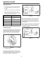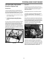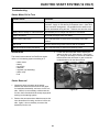
1
R-TEK/DURAFORCE (E) ENGINE SERVICE MANUAL
Table of Contents – Page 1 of 1
PREFACE
SAFETY
SPECIFICATIONS
SPECIAL TOOLS
TROUBLESHOOTING
MAINTENANCE
CARBURETOR
FUEL SYSTEM
IGNITION SYSTEM
REWIND STARTER
ENGINE
PIVOTING ZONE START BRAKE
ELECTRIC START SYSTEM (120 VOLT)
ELECTRIC START SYSTEM (12 VOLT)
PREFACE
ABOUT THIS MANUAL
This manual was written expressly for the E series engines. There are two engines in this series. One is piston
ported (R tek) and the other is a reed valve (DuraForce). As these engines are of the same family, they will both be
covered here. Where there are differences between the two versions, a heading will state which engine is being
discussed. We have made every effort to make this information complete and correct.
We hope that you find this manual a valuable addition to your service shop. If you have questions or comments
regarding this manual, please contact us at the following address:
The Toro Company
Consumer Service Department
8111 Lyndale Ave. So.
Minneapolis, MN 55420-1196
The Toro Company reserves the right to change product specifications or this manual without notice.
TABLE OF CONTENTS
TABLE OF CONTENTS
SAFETY . . . . . . . . . . . . . . . . . . . . . . . . . . . . . . . . . . . . . . . . . . . . . . . . . . . . . . . . . . . . . . . . . . . . . . . . . . . . . . . . . 1
SPECIFICATIONS . . . . . . . . . . . . . . . . . . . . . . . . . . . . . . . . . . . . . . . . . . . . . . . . . . . . . . . . . . . . . . . . . . . . . . . . . 2
Engine Specifications (All dimensions are for a new engine) . . . . . . . . . . . . . . . . . . . . . . . . . . . . . . . . . . . . . .2
Engine Fastener Torque Requirements . . . . . . . . . . . . . . . . . . . . . . . . . . . . . . . . . . . . . . . . . . . . . . . . . . . . . . 3
Standard Torques . . . . . . . . . . . . . . . . . . . . . . . . . . . . . . . . . . . . . . . . . . . . . . . . . . . . . . . . . . . . . . . . . . . . . . .4
Carburetor Specifications . . . . . . . . . . . . . . . . . . . . . . . . . . . . . . . . . . . . . . . . . . . . . . . . . . . . . . . . . . . . . . . . . .4
SPECIAL TOOL REQUIREMENTS . . . . . . . . . . . . . . . . . . . . . . . . . . . . . . . . . . . . . . . . . . . . . . . . . . . . . . . . . . . . 5
TROUBLESHOOTING . . . . . . . . . . . . . . . . . . . . . . . . . . . . . . . . . . . . . . . . . . . . . . . . . . . . . . . . . . . . . . . . . . . . . . .6
Engine Will Not Start When “Cold” . . . . . . . . . . . . . . . . . . . . . . . . . . . . . . . . . . . . . . . . . . . . . . . . . . . . . . . . . . 6
Engine Will Start When “Cold”, But Not When “Hot” . . . . . . . . . . . . . . . . . . . . . . . . . . . . . . . . . . . . . . . . . . . . .6
Engine Will Not Produce Spark . . . . . . . . . . . . . . . . . . . . . . . . . . . . . . . . . . . . . . . . . . . . . . . . . . . . . . . . . . . . .7
Engine Flooded With Fuel . . . . . . . . . . . . . . . . . . . . . . . . . . . . . . . . . . . . . . . . . . . . . . . . . . . . . . . . . . . . . . . . .7
Engine Has Low Compression . . . . . . . . . . . . . . . . . . . . . . . . . . . . . . . . . . . . . . . . . . . . . . . . . . . . . . . . . . . . . .7
Engine Lacks Power . . . . . . . . . . . . . . . . . . . . . . . . . . . . . . . . . . . . . . . . . . . . . . . . . . . . . . . . . . . . . . . . . . . . .8
Engine Surges . . . . . . . . . . . . . . . . . . . . . . . . . . . . . . . . . . . . . . . . . . . . . . . . . . . . . . . . . . . . . . . . . . . . . . . . . .8
Engine Backfires . . . . . . . . . . . . . . . . . . . . . . . . . . . . . . . . . . . . . . . . . . . . . . . . . . . . . . . . . . . . . . . . . . . . . . . .8
Engine Overheats . . . . . . . . . . . . . . . . . . . . . . . . . . . . . . . . . . . . . . . . . . . . . . . . . . . . . . . . . . . . . . . . . . . . . . .9
Engine Vibrates Excessively . . . . . . . . . . . . . . . . . . . . . . . . . . . . . . . . . . . . . . . . . . . . . . . . . . . . . . . . . . . . . . .9
Engine Crankshaft Will Not Turn . . . . . . . . . . . . . . . . . . . . . . . . . . . . . . . . . . . . . . . . . . . . . . . . . . . . . . . . . . . .9
Engine Produces Mechanical Knocking Sound . . . . . . . . . . . . . . . . . . . . . . . . . . . . . . . . . . . . . . . . . . . . . . . . .9
Engine Pre-Ignites . . . . . . . . . . . . . . . . . . . . . . . . . . . . . . . . . . . . . . . . . . . . . . . . . . . . . . . . . . . . . . . . . . . . . .10
Engine Smokes Excessively (Smoke is light colored, engine runs well) . . . . . . . . . . . . . . . . . . . . . . . . . . . . .10
Engine Smokes Excessively (Smoke is dark, engine runs poorly) . . . . . . . . . . . . . . . . . . . . . . . . . . . . . . . . .10
Engine Stalls . . . . . . . . . . . . . . . . . . . . . . . . . . . . . . . . . . . . . . . . . . . . . . . . . . . . . . . . . . . . . . . . . . . . . . . . . .11
Spark Plug Fouled . . . . . . . . . . . . . . . . . . . . . . . . . . . . . . . . . . . . . . . . . . . . . . . . . . . . . . . . . . . . . . . . . . . . . .11
MAINTENANCE . . . . . . . . . . . . . . . . . . . . . . . . . . . . . . . . . . . . . . . . . . . . . . . . . . . . . . . . . . . . . . . . . . . . . . . . . . .13
Recommended Maintenance Schedule . . . . . . . . . . . . . . . . . . . . . . . . . . . . . . . . . . . . . . . . . . . . . . . . . . . . . .13
Air Filter (Mower Only) . . . . . . . . . . . . . . . . . . . . . . . . . . . . . . . . . . . . . . . . . . . . . . . . . . . . . . . . . . . . . . . . . . .14
Spark Plug . . . . . . . . . . . . . . . . . . . . . . . . . . . . . . . . . . . . . . . . . . . . . . . . . . . . . . . . . . . . . . . . . . . . . . . . . . . .14
Cleaning the Exhaust System (Lawn Mower) . . . . . . . . . . . . . . . . . . . . . . . . . . . . . . . . . . . . . . . . . . . . . . . . .15
Cleaning the Exhaust System (Snowthrower) . . . . . . . . . . . . . . . . . . . . . . . . . . . . . . . . . . . . . . . . . . . . . . . . .16
Reassembling Exhaust System (Mower Only) . . . . . . . . . . . . . . . . . . . . . . . . . . . . . . . . . . . . . . . . . . . . . . . . .16
i
TABLE OF CONTENTS
CARBURETOR . . . . . . . . . . . . . . . . . . . . . . . . . . . . . . . . . . . . . . . . . . . . . . . . . . . . . . . . . . . . . . . . . . . . . . . . . . . 17
Identification . . . . . . . . . . . . . . . . . . . . . . . . . . . . . . . . . . . . . . . . . . . . . . . . . . . . . . . . . . . . . . . . . . . . . . . . . . .17
Theory of Operation . . . . . . . . . . . . . . . . . . . . . . . . . . . . . . . . . . . . . . . . . . . . . . . . . . . . . . . . . . . . . . . . . . . . .17
Troubleshooting . . . . . . . . . . . . . . . . . . . . . . . . . . . . . . . . . . . . . . . . . . . . . . . . . . . . . . . . . . . . . . . . . . . . . . . .18
Preliminary Check . . . . . . . . . . . . . . . . . . . . . . . . . . . . . . . . . . . . . . . . . . . . . . . . . . . . . . . . . . . . . . . . . . . . . .19
Removal of DuraForce Carburetor . . . . . . . . . . . . . . . . . . . . . . . . . . . . . . . . . . . . . . . . . . . . . . . . . . . . . . . . . .20
Removal of R tek Carburetor . . . . . . . . . . . . . . . . . . . . . . . . . . . . . . . . . . . . . . . . . . . . . . . . . . . . . . . . . . . . . .20
Disassembly . . . . . . . . . . . . . . . . . . . . . . . . . . . . . . . . . . . . . . . . . . . . . . . . . . . . . . . . . . . . . . . . . . . . . . . . . . .21
Cleaning and Inspection . . . . . . . . . . . . . . . . . . . . . . . . . . . . . . . . . . . . . . . . . . . . . . . . . . . . . . . . . . . . . . . . . .23
Assembly . . . . . . . . . . . . . . . . . . . . . . . . . . . . . . . . . . . . . . . . . . . . . . . . . . . . . . . . . . . . . . . . . . . . . . . . . . . . .23
Installation . . . . . . . . . . . . . . . . . . . . . . . . . . . . . . . . . . . . . . . . . . . . . . . . . . . . . . . . . . . . . . . . . . . . . . . . . . . .25
Governor Theory . . . . . . . . . . . . . . . . . . . . . . . . . . . . . . . . . . . . . . . . . . . . . . . . . . . . . . . . . . . . . . . . . . . . . . .26
Reed Valve Engine (DuraForce Engines Only) . . . . . . . . . . . . . . . . . . . . . . . . . . . . . . . . . . . . . . . . . . . .26
Piston Ported Engine (R tek Engines Only) . . . . . . . . . . . . . . . . . . . . . . . . . . . . . . . . . . . . . . . . . . . . . . .26
Presetting the Governor (DuraForce Engines Only) . . . . . . . . . . . . . . . . . . . . . . . . . . . . . . . . . . . . . . . . 26
Servicing the Air Filter (DuraForce Engines Only) . . . . . . . . . . . . . . . . . . . . . . . . . . . . . . . . . . . . . . . . . .27
FUEL SYSTEM . . . . . . . . . . . . . . . . . . . . . . . . . . . . . . . . . . . . . . . . . . . . . . . . . . . . . . . . . . . . . . . . . . . . . . . . . . .29
Operation . . . . . . . . . . . . . . . . . . . . . . . . . . . . . . . . . . . . . . . . . . . . . . . . . . . . . . . . . . . . . . . . . . . . . . . . . . . . .29
Fuel Cap Service . . . . . . . . . . . . . . . . . . . . . . . . . . . . . . . . . . . . . . . . . . . . . . . . . . . . . . . . . . . . . . . . . . . . . . .29
Cleaning . . . . . . . . . . . . . . . . . . . . . . . . . . . . . . . . . . . . . . . . . . . . . . . . . . . . . . . . . . . . . . . . . . . . . . . . . . . . . .29
IGNITION SYSTEM . . . . . . . . . . . . . . . . . . . . . . . . . . . . . . . . . . . . . . . . . . . . . . . . . . . . . . . . . . . . . . . . . . . . . . . .31
Troubleshooting . . . . . . . . . . . . . . . . . . . . . . . . . . . . . . . . . . . . . . . . . . . . . . . . . . . . . . . . . . . . . . . . . . . . . . . .31
Testing . . . . . . . . . . . . . . . . . . . . . . . . . . . . . . . . . . . . . . . . . . . . . . . . . . . . . . . . . . . . . . . . . . . . . . . . . . . . . . .31
Spark Plug Operation . . . . . . . . . . . . . . . . . . . . . . . . . . . . . . . . . . . . . . . . . . . . . . . . . . . . . . . . . . . . . . . . . . . .31
Spark Plug Service . . . . . . . . . . . . . . . . . . . . . . . . . . . . . . . . . . . . . . . . . . . . . . . . . . . . . . . . . . . . . . . . . . . . . .32
CD Pack Operation . . . . . . . . . . . . . . . . . . . . . . . . . . . . . . . . . . . . . . . . . . . . . . . . . . . . . . . . . . . . . . . . . . . . .32
CD Pack Air Gap Adjustment . . . . . . . . . . . . . . . . . . . . . . . . . . . . . . . . . . . . . . . . . . . . . . . . . . . . . . . . . . . . . .33
CD Pack Removal/Installation . . . . . . . . . . . . . . . . . . . . . . . . . . . . . . . . . . . . . . . . . . . . . . . . . . . . . . . . . . . . .33
Flywheel Operation . . . . . . . . . . . . . . . . . . . . . . . . . . . . . . . . . . . . . . . . . . . . . . . . . . . . . . . . . . . . . . . . . . . . .34
Flywheel Removal . . . . . . . . . . . . . . . . . . . . . . . . . . . . . . . . . . . . . . . . . . . . . . . . . . . . . . . . . . . . . . . . . . . . . .34
Flywheel Installation . . . . . . . . . . . . . . . . . . . . . . . . . . . . . . . . . . . . . . . . . . . . . . . . . . . . . . . . . . . . . . . . . . . . .35
ii
TABLE OF CONTENTS
REWIND STARTER . . . . . . . . . . . . . . . . . . . . . . . . . . . . . . . . . . . . . . . . . . . . . . . . . . . . . . . . . . . . . . . . . . . . . . . .37
Operation . . . . . . . . . . . . . . . . . . . . . . . . . . . . . . . . . . . . . . . . . . . . . . . . . . . . . . . . . . . . . . . . . . . . . . . . . . . . .37
Removal and Disassembly . . . . . . . . . . . . . . . . . . . . . . . . . . . . . . . . . . . . . . . . . . . . . . . . . . . . . . . . . . . . . . . .37
Reassembly . . . . . . . . . . . . . . . . . . . . . . . . . . . . . . . . . . . . . . . . . . . . . . . . . . . . . . . . . . . . . . . . . . . . . . . . . . .37
ENGINE . . . . . . . . . . . . . . . . . . . . . . . . . . . . . . . . . . . . . . . . . . . . . . . . . . . . . . . . . . . . . . . . . . . . . . . . . . . . . . . . .39
General Information . . . . . . . . . . . . . . . . . . . . . . . . . . . . . . . . . . . . . . . . . . . . . . . . . . . . . . . . . . . . . . . . . . . . .39
Theory of Operation . . . . . . . . . . . . . . . . . . . . . . . . . . . . . . . . . . . . . . . . . . . . . . . . . . . . . . . . . . . . . . . . . . . . .39
Reed Valve Engine . . . . . . . . . . . . . . . . . . . . . . . . . . . . . . . . . . . . . . . . . . . . . . . . . . . . . . . . . . . . . . . . . .39
Piston Ported Engine . . . . . . . . . . . . . . . . . . . . . . . . . . . . . . . . . . . . . . . . . . . . . . . . . . . . . . . . . . . . . . . .40
Both Piston Ported and Reed Valve Engines . . . . . . . . . . . . . . . . . . . . . . . . . . . . . . . . . . . . . . . . . . . . . .40
Service Tips . . . . . . . . . . . . . . . . . . . . . . . . . . . . . . . . . . . . . . . . . . . . . . . . . . . . . . . . . . . . . . . . . . . . . . . . . . .41
Disassembly . . . . . . . . . . . . . . . . . . . . . . . . . . . . . . . . . . . . . . . . . . . . . . . . . . . . . . . . . . . . . . . . . . . . . . . . . . .41
Inspection and Repair . . . . . . . . . . . . . . . . . . . . . . . . . . . . . . . . . . . . . . . . . . . . . . . . . . . . . . . . . . . . . . . . . . .42
Reed Valve Service (DuraForce Engines Only) . . . . . . . . . . . . . . . . . . . . . . . . . . . . . . . . . . . . . . . . . . . . . . . .43
Reassembly . . . . . . . . . . . . . . . . . . . . . . . . . . . . . . . . . . . . . . . . . . . . . . . . . . . . . . . . . . . . . . . . . . . . . . . . . . .44
Reinstalling External Components . . . . . . . . . . . . . . . . . . . . . . . . . . . . . . . . . . . . . . . . . . . . . . . . . . . . . . . . . .45
Crankshaft Seal Replacement . . . . . . . . . . . . . . . . . . . . . . . . . . . . . . . . . . . . . . . . . . . . . . . . . . . . . . . . . . . . .46
PIVOTING ZONE START BRAKE . . . . . . . . . . . . . . . . . . . . . . . . . . . . . . . . . . . . . . . . . . . . . . . . . . . . . . . . . . . . .47
Introduction . . . . . . . . . . . . . . . . . . . . . . . . . . . . . . . . . . . . . . . . . . . . . . . . . . . . . . . . . . . . . . . . . . . . . . . . . . .47
Operation . . . . . . . . . . . . . . . . . . . . . . . . . . . . . . . . . . . . . . . . . . . . . . . . . . . . . . . . . . . . . . . . . . . . . . . . . . . . .47
Disassembly . . . . . . . . . . . . . . . . . . . . . . . . . . . . . . . . . . . . . . . . . . . . . . . . . . . . . . . . . . . . . . . . . . . . . . . . . . .48
Assembly. . . . . . . . . . . . . . . . . . . . . . . . . . . . . . . . . . . . . . . . . . . . . . . . . . . . . . . . . . . . . . . . . . . . . . . . . . . . . 49
ELECTRIC START SYSTEM (120 VOLT) . . . . . . . . . . . . . . . . . . . . . . . . . . . . . . . . . . . . . . . . . . . . . . . . . . . . . . .51
Troubleshooting . . . . . . . . . . . . . . . . . . . . . . . . . . . . . . . . . . . . . . . . . . . . . . . . . . . . . . . . . . . . . . . . . . . . . . . .51
Introduction . . . . . . . . . . . . . . . . . . . . . . . . . . . . . . . . . . . . . . . . . . . . . . . . . . . . . . . . . . . . . . . . . . . . . . . . . . .51
Starter Removal . . . . . . . . . . . . . . . . . . . . . . . . . . . . . . . . . . . . . . . . . . . . . . . . . . . . . . . . . . . . . . . . . . . . . . . 51
Starter Disassembly . . . . . . . . . . . . . . . . . . . . . . . . . . . . . . . . . . . . . . . . . . . . . . . . . . . . . . . . . . . . . . . . . . . . .52
Starter Assembly . . . . . . . . . . . . . . . . . . . . . . . . . . . . . . . . . . . . . . . . . . . . . . . . . . . . . . . . . . . . . . . . . . . . . . .52
Starter Installation . . . . . . . . . . . . . . . . . . . . . . . . . . . . . . . . . . . . . . . . . . . . . . . . . . . . . . . . . . . . . . . . . . . . . .52
iii
TABLE OF CONTENTS
ELECTRIC START SYSTEM (12 VOLT) . . . . . . . . . . . . . . . . . . . . . . . . . . . . . . . . . . . . . . . . . . . . . . . . . . . . . . . .53
Troubleshooting . . . . . . . . . . . . . . . . . . . . . . . . . . . . . . . . . . . . . . . . . . . . . . . . . . . . . . . . . . . . . . . . . . . . . . . .53
Introduction . . . . . . . . . . . . . . . . . . . . . . . . . . . . . . . . . . . . . . . . . . . . . . . . . . . . . . . . . . . . . . . . . . . . . . . . . . .53
Starter Removal . . . . . . . . . . . . . . . . . . . . . . . . . . . . . . . . . . . . . . . . . . . . . . . . . . . . . . . . . . . . . . . . . . . . . . . .53
Starter Testing . . . . . . . . . . . . . . . . . . . . . . . . . . . . . . . . . . . . . . . . . . . . . . . . . . . . . . . . . . . . . . . . . . . . . . . . .54
Starter Disassembly . . . . . . . . . . . . . . . . . . . . . . . . . . . . . . . . . . . . . . . . . . . . . . . . . . . . . . . . . . . . . . . . . . . . .54
Starter Assembly . . . . . . . . . . . . . . . . . . . . . . . . . . . . . . . . . . . . . . . . . . . . . . . . . . . . . . . . . . . . . . . . . . . . . . .55
Starter Installation . . . . . . . . . . . . . . . . . . . . . . . . . . . . . . . . . . . . . . . . . . . . . . . . . . . . . . . . . . . . . . . . . . . . . .55
Alternator Introduction . . . . . . . . . . . . . . . . . . . . . . . . . . . . . . . . . . . . . . . . . . . . . . . . . . . . . . . . . . . . . . . . . . .56
Alternator Output Testing . . . . . . . . . . . . . . . . . . . . . . . . . . . . . . . . . . . . . . . . . . . . . . . . . . . . . . . . . . . . . . . . .57
Alternator Air Gap Adjustment . . . . . . . . . . . . . . . . . . . . . . . . . . . . . . . . . . . . . . . . . . . . . . . . . . . . . . . . . . . . .57
Alternator Resistance Check . . . . . . . . . . . . . . . . . . . . . . . . . . . . . . . . . . . . . . . . . . . . . . . . . . . . . . . . . . . . . .57
Cup Assembly Test . . . . . . . . . . . . . . . . . . . . . . . . . . . . . . . . . . . . . . . . . . . . . . . . . . . . . . . . . . . . . . . . . . . . .57
iv
SAFETY
SAFETY INFORMATION
General
This safety symbol means WARNING or PERSONAL SAFETY INSTRUCTION - read the instruction
because it has to do with your safety. Failure to comply with the instruction may result in personal
injury or even death.
This manual is intended as a service and repair manual only. The safety instructions provided herein are for
troubleshooting, service, and repair of the engine only. The individual Operator’s manual will contain safety
information on the complete product powered by the E series engine. Operator’s manuals with complete
instructions are available through:
Lawn-Boy Corporation / The Toro Company
Parts Department
8111 Lyndale Avenue South
Bloomington, MN 55420 U.S.A.
Safety Tips
Avoid unexpected starting of engine...
Always turn off the powered product and disconnect the
spark plug wire before attempting cleaning, adjustment,
or repair.
Avoid accidental misuse of fuel...
Always store fuel in a properly labeled container
designed for gasoline.
Avoid injury due to inferior parts...
Use only Toro/Lawn-Boy original parts to ensure that
important safety criteria are met.
Avoid lacerations and amputations...
Stay clear of all moving parts whenever the engine is
running. Treat all normally moving parts as if they were
moving whenever the engine is running or has the
potential to start.
Avoid injury to bystanders...
Always clear the area of bystanders before starting or
testing powered equipment.
Avoid burns...
.Do not touch the engine while it is running or shortly
after it has been running.
Avoid injury due to projectiles...
Always clear the area of sticks, rocks, or any other
debris that could be picked up and thrown by the
powered equipment. Keep all safety shields in place.
Avoid Falls...
Do not operate the powered product on slippery
surfaces or if footing is questionable.
Avoid modifications...
Never alter or modify any part unless it is a factory
approved procedure.
Avoid fires...
Wipe up any spilled fuel or oil immediately.
Avoid unsafe operation...
Always test the safety systems after making
adjustments or repairs on the machine.
Avoid asphyxiation...
Never operate an engine in a confined area without
proper ventilation.
Avoid fires and explosions...
Use a container designed for gasoline. Avoid spilling
fuel and never smoke while working with any type of
fuel.
1
SPECIFICATIONS
Specifications
Engine Specifications (All dimensions are for a new engine)
Item
DuraForce
R tek
Type
Reed valve 2-cycle
Piston ported 2-cycle
2.5000" + .0005 (63.5mm + .0127)
Bore
1.75" (44.45mm)
Stroke
Wrist pin diameter
.5000" + .0000 - .0002 (12.70mm + .000 - .005)
Crankpin diameter
.7427" + .0003 - .0002 (18.85mm + .008 - .005)
End play (crankshaft)
.
Side play (crankshaft) near lower main
0 - .017" (0 - .431mm) 1998 Snow
0 - .0215" (0 - .533mm) 1999 and
later Snow
0 - .017" (0 - .431mm) Walk mower
.
.0006" + .0003 - .0006 (.015mm + .008 - .015)
Piston cyl. Clearance (tightest loc.)
.0035" to .0059" (.089 to .150mm)
Wrist pin hole diameter
.500"/.5005" (12.705mm / 12.712mm)
Bottom ring thickness, new
.0600 + .0005 (1.52mm + .013)
End gap, new (both rings)
.016/.008 in. (.40/.20mm)
8.6 cu in. (141cc)
Displacement
Horsepower
6.5HP
4 or 5HP
5.8:1
Compression ratio
Compression
Carburetor
Fuel required
Approximately 115 psi. Service limit 80 psi.
Dual-circuit Lawn-Boy with fixed jets, float type with primer and choke
Unleaded regular (87 octane R+M/2):2-cycle oil
Mix ratio
Recommended Oil
.
32:1
50:1
Lawn-Boy Generation II 2-cycle
oil or NMMA TCW3
Toro 2-cycle oil or NMMA TCW3
Fuel tank capacity
Varies with product
Solid-state CD Pack, magneto type
Ignition type
.010" (.25mm)
CD Pack air gap
Spark plug / air gap
Start system
NGK projected nose / NGK BPMR4A .030" (.76mm)
Rope rewind or 12 VDC
Air vane
Governor
Governed Engine Speed
.
Rope rewind or 120 VAC
2900 + 300 rpm
.
4HP runs at 3700 + 300
CCR 2400 - 3700
5HP runs at 3800 + 300 rpm
CCR 2450 & 2500 - 3800 rpm
CCR 3600 - 3900 rpm
CCR 3650 - 4000 rpm
Snow Commander - 4000 rpm
All snow engines are + 300 rpm
Idle Speed
Air Cleaner
.
2200 - 2800 rpm
Oiled foam type with Centrifugal
pre-cleaner
2
N/A
N/A
SPECIFICATIONS
Item
DuraForce
R tek
Choke
Manual, butterfly type
Fuel filter
In-tank and in-carburetor
Cast iron, semi-keystone top ring. Second ring is rectangular.
Anti-rotation pin in piston.
Piston rings
Piston
Permanent mold, high silicon aluminum
Engine Fastener Torque Requirements
Item
DuraForce
R tek
Bolt, Head
140 - 200 in. lbs. (16 - 22 Nm)
140 - 200 in. lbs. (16 - 22 Nm)
Jet, Main
4 - 6 in. lbs. (.44 - .66 Nm)
4 - 6 in. lbs. (.44 - .66 Nm)
Jet, Pilot*
10 - 12 in. lbs. (1.1 - 1.3 Nm)
6 - 8 in. lbs. (.66 - .88 Nm)*
Nozzle, Carburetor*
16 - 28 in. lbs. (1.7- 4.0 Nm)
20 - 30 in. lbs. (2.2 - 3.4 Nm)
Nut, Blade
45 - 50 ft. in. (60 - 67 Nm)
NA
Nut, Flywheel
375 - 425 in. lbs. (42 - 47 Nm)
375 - 425 in. lbs. (42 - 47 Nm)
Seat, Float Valve*
16 - 28 in. lbs. (1.7 - 4.0 Nm)
22-32 in. lbs. (2.4 - 3.5 Nm)
Screw, Brake Plate Assembly
60 - 70 in. lbs. (6.7 - 7.8 Nm)
NA
Screw, Carburetor Mounting
20 - 30 in. lbs. (2.2 - 3.4 Nm)
20 - 30 in. lbs. (2.2 - 3.4 Nm)
Screw, CD Ignition Pack
90 - 110 in. lbs. (10 - 12 Nm)
90 - 110 in. lbs. (10 - 12 Nm)
Screw, Cylinder to Crankcase
55 - 90 in. lbs. (6.2 - 10.0 Nm)
55 - 90 in. lbs. (6.2 - 10.0 Nm)
Screws, Engine Mounting
170 - 220 in. lbs. (19 - 25 Nm)
170 - 220 in. lbs. (19 - 25 Nm)
Screw, Float Bowl
10 - 13 in. lbs. (1.1 - 1.5 Nm)
10 - 13 in. lbs. (1.1 - 1.5 Nm)
Screw, Muffler (611228)
55 - 90 in. lbs. (6.2 - 10.0 Nm)
55 - 90 in. lbs. (6.2 - 10.0 Nm)
Screw, Muffler Cover
55 - 90 in. lbs. (6.2 - 10.0 Nm)
NA
Screw, Muffler Plate
140 - 200 in. lbs. (16 - 22 Nm)
NA
Screw, Reed
10 - 13 in. lbs. (1.1 - 1.5 Nm)
NA
Screw, Rod Cap to Rod
65 - 75 in. lbs. (7.3 - 8.4 Nm)
65 - 75 in. lbs. (7.3 - 8.4 Nm)
Screw, Shroud
58 - 70 in. lbs. (6.5 - 7.8 Nm)
58 - 70 in. lbs. (6.5 - 7.8 Nm)
Screw, Shroud Base
58 - 70 in. lbs. (6.5 - 7.8 Nm)
58 - 70 in. lbs. (6.5 - 7.8 Nm)
Spark Plug
150 - 200 in. lbs. (17 - 23 Nm)
150 - 200 in. lbs. (17 - 23 Nm)
Rewind Starter to blower housing
NA
20-30 in. lbs. (2.2 - 3.4 Nm)
Screw, Manifold
NA
55 - 70 in. lbs. (6.2 - 7.8 Nm)
Screw, Muffler
NA
100 - 130 in. lbs.
* Overtorquing will crack the carb body and cause the engine to run rich
3
page rev 8/06
SPECIFICATIONS
Item
DuraForce
R tek
Nut, Shroud
100 - 130 in. lbs. (10 - 14 Nm)
140 - 170 in. lbs. (16 - 19 Nm)
Screw, Starter Bracket to Recoil
NA
30 - 35 in. lbs. (3.4 - 3.8 Nm)
Screw, Gov Pivot Block to Cyl.
NA
30 - 35 in. lbs. (3.4 - 3.8 Nm)
Screw, Elect Start to Crankcase
140 - 200 in. lbs. (16 - 22 Nm)
75 - 100 in. lbs. (8.2 - 11 Nm)
Standard Torques
Size
US (Metric)
#10 - 24
20 - 30 in. lbs. (5.1 - 6.21 Nm)
1/4 - 20
55 - 90 in. lbs. (6.2 - 10.0 Nm)
5/16 - 18
140 - 200 in. lbs. (16 - 22 Nm)
Carburetor Specifications
Item
Type
DuraForce
R tek
Lawn-Boy, float type, dual-circuit, with primer and choke
Body Material
Minlon
Seat material
Brass with Viton tipped needle. Both are replaceable.
5 psi (.7 kg/cm2) (Wet)
Inlet Needle “Pop-Off” Pressure
Main Jet
77.5
Main Nozzle
Brass
Pilot Jet
37.5
High Altitude
Float Adjustment
73.8
42.5
NA
Float height .500 ± .030" bowl flange (no gasket) to top of float
4
SPECIAL TOOLS
SPECIAL TOOL REQUIREMENTS
Listing
Description
Order From
Part Number
Comments/Use
Air Gap Gauge
Toro
604659
Sets .010” (.25 mm) gap between flywheel
and coil
Piston Ring Compressor
OTC
TOR 4089
Compresses piston rings to allow installation
into the cylinder
Wrist Pin Knockout Tool
Toro
602884
Used to drive wrist pin out of piston
OTC Tool & Equipment Division
SPX Corporation
Industrial Park
2013 4th Street NW
Owatonna, MN 55060
Telephone: 800-533-0492
Fax:
507-455-7011
5
TROUBLESHOOTING
TROUBLESHOOTING
Engine Will Not Start When “Cold”
Possible Causes
Remedies
Fuel tank is empty
Fill with clean, fresh, properly-mixed, unleaded fuel
Bad fuel
Drain tank and float bowl. Fill the tank with clean, fresh,
unleaded, properly-mixed fuel.
Fuel filter plugged
Replace fuel tank
Air cleaner plugged
Wash and re-oil air cleaner element (DuraForce only)
Fouled spark plug
Remove and replace the spark plug
No spark at spark plug
See “Engine Will Not Produce Spark” table
Insufficient momentum
Check for loose blade, mower only
Incorrect ignition timing
Check for sheared flywheel key
Low compression
See “Engine Has Low Compression” table
Engine flooded with fuel
See “Engine Flooded With Fuel” table
Reed valves not closed
Replace reed valves (DuraForce only)
Reed valves stuck closed
Free up and run engine to clean (DuraForce only)
Primer or choke not operating
Fix or replace
Engine Will Start When “Cold”, But Not When “Hot”
Possible Causes
Remedies
Engine is flooded
See “Engine Flooded With Fuel” table
Excessive alcohol in fuel
Use no more than 10% ethanol blend. Avoid methanol
Engine is overheated
See “Engine Overheats” table
Clogged bowl vent
Clean bowl vent
Fuel percolation (vapor lock)
Use current season gas for fuel mixture
6
TROUBLESHOOTING
Engine Will Not Produce Spark
Possible Causes
Remedies
Spark plug wire disconnected
Reconnect spark plug wire
Spark plug fouled or damaged
Replace spark plug
Spark plug wire damaged
Replace CD pack
Coil kill wire grounded
Locate and eliminate the unwanted ground
Ignition coil failed
Replace CD pack
Flywheel magnets weak
Replace flywheel
Engine Flooded With Fuel
Possible Causes
Remedies
Overuse of choke position
Take throttle off choke
Throttle cable misadjusted
Adjust throttle cable, if present
Air cleaner plugged
Wash and re-oil air cleaner element (DuraForce only)
Fouled spark plug
Replace spark plug
Carburetor inlet needle stuck open or leaking
Clean carburetor, replace failed parts, and pressure test
Carburetor Air Vent
Clean Air Vent
Engine Has Low Compression
Possible Causes
Remedies
Worn piston rings
Replace piston rings or short block
Piston ring(s) stuck in groove
Replace piston and rings
Cylinder worn
Remove and replace short block
7
TROUBLESHOOTING
Engine Lacks Power
Possible Causes
Remedies
Dull blade
Sharpen or replace blade, mower only
Housing choked with grass and debris
Clean housing thoroughly, mower only
Plugged exhaust system
Clean exhaust ports
Muffler plugged
Clean or replace muffler
Flywheel key sheared
Replace flywheel key
Carburetor dirty
Clean carburetor
Intake air leak
Repair or replace failed components(s)
Low compression
See “Engine Has Low Compression” table
Engine Surges
Possible Causes
Remedies
Fouled idle circuit
Clean idle circuit
Air leak
Check sealing surfaces, oil seals, gaskets, and port plugs
Restricted fuel flow
Check filters and fuel line
Engine RPM low
Adjust to proper specification. Note: A slight surge at no
load is normal.
Governor link misadjusted (R tek)
Adjust
Air vane sticking
Clean or replace
Engine Backfires
Possible Causes
Remedies
Flywheel key sheared
Replace key
Muffler filled with carbon
Clean muffler
Exhaust ports plugged
Clean ports
Air leak to crankcase
Replace seals or re-seal crankcase to cylinder
Spark plug partly fouled
Clean or replace
8
TROUBLESHOOTING
Engine Overheats
Possible Causes
Remedies
Cylinder head cooling fins clogged
Clean fins thoroughly
Restricted carburetor jets
Clean carburetor and jet
Improper gas to oil mix ratio
Ensure mixture is correct
Cooling air intake plugged
Remove foreign material and clean
Engine Vibrates Excessively
Possible Causes
Remedies
Blade out of balance
Balance blade or replace if damaged
Bent blade
Replace blade
Loose engine mounting screws
Tighten engine mounting screws (engine to plate, plate
to mower housing)
Bent crankshaft
Replace crankshaft
Flywheel out of balance (damaged)
Replace flywheel
Engine Crankshaft Will Not Turn
Possible Causes
Remedies
Engine brake incorrectly engaged
Disengage brake and inspect and repair as necessary,
mower only
Blade jammed in housing
Inspect and repair or replace, mower only
Piston seized in its cylinder
Inspect and repair or replace
Starter jammed
Repair starter
Engine Produces Mechanical Knocking Sound
Possible Causes
Remedies
Loose blade
Inspect and tighten blade nut to correct torque, mower
only
Loose flywheel
Inspect and tighten flywheel nut to correct torque
Pre-ignition is occurring
See “Engine Pre-Ignites” table
Loose rod cap
Replace rod and bearings
Loose engine mounting bolts
Tighten bolts
9
TROUBLESHOOTING
Engine Pre-Ignites
Possible Causes
Remedies
Wrong spark plug - too hot
Install the correct type of spark plug
Low quality fuel (old or stale)
Replace with fresh, unleaded regular fuel
Carbon buildup in engine
Decarbon engine and muffler
Excessive alcohol in fuel
Replace with fresh unleaded fuel having no more than
10% ethanol
Sheared flywheel key
Inspect and repair
Engine Smokes Excessively (Smoke is light colored, engine runs well)
Possible Causes
Remedies
Slight oil accumulation in crankcase
None; normal on start-up
Air cleaner element clogged
Clean and re-oil or replace air cleaner element, mower
only
Fuel/oil mixture too rich
Drain fuel tank and fill with fuel of correct mixture
Choke is in “On” position
Move to high speed or “Off” position
Engine Smokes Excessively (Smoke is dark, engine runs poorly)
Possible Causes
Remedies
Carburetor running too rich
Clean and check carburetor
Choke is in “On” position
Move to high speed or “Off” position
10
TROUBLESHOOTING
Engine Stalls
Possible Causes
Remedies
Engine out of fuel
Refill with fresh fuel of the correct mixture
Engine overloaded
Unload engine and restart
Fuel filter plugged
Clean fuel filter/tank
Spark plug fouled
See “Spark Plug Fouled” table
Fuel cap vent plugged
Replace fuel cap
Ignition inadvertently grounded
Inspect and repair to remove unwanted ground
Carburetor vent plugged
Clear vent of obstruction
Engine overheated
Clear debris from fins or cause of overheating
Improper lubrication
Tear down and inspect for damage
Spark Plug Fouled
Possible Causes
Remedies
Incorrect spark plug
Use correct spark plug
Carburetor running too rich
Clean/rebuild carburetor
Clogged air cleaner element
Clean and re-oil element or replace, mower only
Overuse of “choke” position
Move control off “choke” position and check throttle
cable adjustment
Weak ignition system
Replace CD ignition pack
Worn rings and/or cylinder
Rebuild engine or short block
Use of poor fuel
Drain fuel tank and replace with fresh, unleaded regular
fuel having the correct oil mixture
Fuel/oil mixture too rich
Drain fuel tank and fill with fuel of correct mixture
Wrong Oil
Use Toro 2-cycle oil, Lawn-Boy DuraForce oil, or
NMMA TCW3 approved oil
11
THIS PAGE INTENTIONALLY LEFT BLANK
12
MAINTENANCE
Recommended Maintenance Schedule
Frequency
Item
Comments
5 Hours
Fasteners
Check blade and engine mounting fasteners
frequently. Keep all nuts, bolts, and screws
tight to ensure safe operation.
25 Hours
Housing
(Mower only.) Remove the buildup of grass
clippings and dirt.
(Self-propelled mower only.) Clean grass
clippings and debris under drive belt
mechanism cover and drive belt.
50 Hours
Spark Plug
Clean, inspect, and regap; replace if
necessary.
Air Filter
(Mower only.) Remove and clean each
mowing season or every 50 hours; more
frequently if operating conditions are dusty.
Blade
(Mower only.) Sharpen or replace; maintain
more frequently if edge is dulled quickly in
rough or sandy conditions.
Blade Brake
Check stopping time every 50 hours or at start
of each mowing season. Blade must stop
within 3 seconds of releasing bail. If not,
repair or replace.
100 Hours
Lubrication
(Self-propelled mowers only.) Grease rear
height adjuster brackets.
Exhaust Ports
Clean every 50 hours or at least once each
season.
Fuel System
Check for leakage and/or deterioration of fuel
hose. Replace if necessary.
Cooling System
Clean grass clippings, debris, or dirt that clog
engine air cooling fins; clean more frequently
under dirty or high chaff conditions.
13
MAINTENANCE
Air Filter (Mower Only)
Note: Be sure filter is properly seated in air box and
is not puckered (allowing direct passage of air and
dirt to carburetor).
Once every season, or every 50 hours, clean the air
filter housing and element. Do so more frequently
under dusty conditions.
Note: Do not operate the engine without the air filter in
place. Doing so may damage the engine or cause
excessive engine wear.
1. To remove air filter (A), snap cover latch open,
swing to side, and unhook. Remove the cover (B)
and air filter. (See Figure 1.)
Figure 3
3297-007
Spark Plug
A spark plug that is dirty, pitted, carbon covered, or has
worn electrodes may cause hard starting and poor
operation.
Replace spark plug once a season or every 25 hours,
which ever occurs first. Use NGK BPMR 4A or
equivalent.
Figure 1
1. Set spark plug gap to .030 (.76 mm). (See
Figure 4.)
3297-005
2. Wash air filter in laundry detergent and water.
Squeeze filter to remove excess liquid and blot dry
with a paper towel or rag (see Figure 2). Do not
wring out the element or damage may occur.
IIIIII
IIIIII
IIIIII
.030 in. (.76mm)
Figure 4
3297-008
2. Install spark plug finger tight, then torque per
specifications. (See Figure 5.)
Figure 2
3329-006
3. Apply one tablespoon SAE 30 or similar oil to the
air filter (see Figure 3). Lightly squeeze filter until
oil is distributed evenly throughout the filter. Blot
lightly with paper towel to remove excess oil.
Replace filter with cleanest side facing carburetor.
Figure 5
14
3297-009
MAINTENANCE
Cleaning the Exhaust System (Lawn
Mower)
Warning: Disconnect the spark plug wire to prevent
accidentally starting the engine.
A
1. (Mower) Using a 1/2" drive with a 15/16" socket,
remove the blade nut that secures both the mulch
fan and blade to the engine. Use heavy-duty
gloves to hold the blade while removing the nut.
(See Figure 6.) Note: Removing the blade is
merely for convenience while working.
B
Figure 8
1657-001
3. With the cover and exhaust pipe removed, you can
see into the passage leading to the exhaust port of
the engine (A) and passage to the muffler (B). If
the exhaust requires cleaning, remove the engine
and separate the engine and base for access to
the exhaust ports. If the muffler requires cleaning,
it can be removed by removing the 2 screws on
either side of the muffler passage (see Figure 8)
and one through the side of the muffler (see A in
Figure 9). Use a stick of wood to scrape the
carbon loose. Do not use a metal scraper.
Figure 6
0893-011
(Snowthrower) Remove 2 bolts holding the muffler to
the engine block. Remove the muffler. Proceed to
step 3.
2. Remove the cover and the exhaust pipe under the
cover. (See Figure 7.)
A
B
Figure 9
16057-009
4. The muffler (B) can be removed from the top of the
mower to inspect for carbon buildup. (See Figure
9.)
Figure 7
1657-010
15
MAINTENANCE
Cleaning the Exhaust System
(Snowthrower)
Reassembling Exhaust System
(Mower Only)
1. Remove the muffler (see Figure 10.) Clean as
needed.
1. Install the exhaust pipe into the engine base (see
Figure 12).
Figure 12
Figure 10
0893-012
16547-006
2. The cover on the exhaust portion of the engine
base uses a high temperature silicone to seal the
joint. Apply a coat of Loctite 598 or equivalent to
the sealing surfaces before assembly. Torque the
four screws per specifications.
2. Inspect exhaust port (see Figure 11). If cleaning is
necessary, rotate piston to cover exhaust port, and
scrape carbon from exhaust port area. Use wood
only to clean this area.
3. Re-install the blade and mulch fan, if removed.
Tighten the nut per specifications.
Figure 11
0893-035
3. Install the muffler and torque the bolts per
specifications.
16
CARBURETOR
Identification
The E series engines use two versions of the primer
start carburetor. One with an air filter box on the
mower engines (DuraForce) and one without an air
filter box on the snowthrower engines (R tek).
Differences include a plug in the snowthrower
carburetor vent passage and some minor differences in
the throttle shafts, jetting and throttle valve bleed hole.
Both carburetors have two circuits and use both a
choke and primer for starting. (See Figure 13.)
Figure 14
3297-012
A. Venturi
C. Air Pressure
B. Center Passage Area
The fuel/oil mix is then picked up by, and mixed with,
the moving air, the amount of fuel determined by
throttle opening and jet size. This fuel/oil/air mixture
enters the crankcase through the reed valves
(DuraForce), or ports (R tek). (See Figure 15 and
Figure 16.) When the piston moves away from the
spark plug, the cylinder intake ports are opened and
the now pressurized crankcase causes the mixture to
move into the combustion chamber.
Reed Valve
Figure 13
0720-012
Theory of Operation
As the crankshaft rotates, the piston moves back and
forth in the cylinder, alternately creating a pressure or a
partial vacuum in the crankcase. (See Figure 16.)
As the piston moves toward the spark plug, the reed
valve opens (see Figure 15) or the inlet ports are
uncovered (see Figure 16). This causes air to rush
through the carburetor throat to equalize the pressure
in the crankcase. The carburetor throat is formed into
a venturi (large at each end but with a smaller center
passage). When air rushes through the venturi, air
pressure at the center of the passage is lowered.
Figure 15
3297-021-3
A. Reed Valve Closed
C. Second Stroke
B. Exhaust Gases
Piston Ported
By inserting a tube from the carburetor float bowl into
the venturi (see Figure 14), the lower air pressure at
the venturi causes the normal air pressure in the bowl
to push fuel up the tube.
Figure 16
3297-002
A. Intake Ports Closed C. Third Port Open
D. Partial Vacuum
B. Ignition
17
CARBURETOR
Troubleshooting
Engine Starts Hard
Possible Causes
Remedies
Primer malfunction
Repair or replace as necessary
No fuel in carburetor
Add the proper fuel-oil mix
Carburetor bolts loose
Tighten bolts to 20 - 30 in.lbs. (2.2 - 6.2 Nm)
Mislocated gaskets
Loosen bolts, realign gaskets, and tighten
Choke not closing fully
Adjust choke or throttle/choke cable
Engine Runs Rich
Possible Causes
Remedies
Dirty air cleaner
Clean or replace and re-oil air filter element
(DuraForce engines)
Dirt in carburetor
Clean carburetor, fuel line and tank
Primer line pinched
Inspect and correct problem
Dirt in primer vent
Clean and/or replace as necessary
Choke not opening fully
Adjust choke or throttle/choke cable
Engine Runs Lean
Possible Causes
Remedies
Carburetor bolts not tight
Tighten bolts to specifications
Crankcase gaskets or seals leaking
Replace or reseal
Main jet partially clogged
Clean jet
Pilot jet or circuit clogged
Clean pilot jet and passages
Fuel Leaks From Carburetor (Leaking is continuous and fully drains fuel tank)
Possible Causes
Remedies
Dirt under inlet needle
Remove inlet needle and seat. Then clean or replace
and pressure check.
Bowl vent plugged
Remove bowl and clean with compressed air
Float sinking (heavy)
Replace float
Float stuck (gummed carburetor)
Remove bowl and clean carburetor
18
CARBURETOR
Fuel Leaks From Carburetor (Leaking starts after running, stops after shutdown)
Note: This condition which does NOT drain the fuel tank is called “spit-back”.
Possible Causes
Remedies
Engine RPM out of proper range
Adjust to proper range (experimentation within the
RPM range may be necessary)
Exhaust partially plugged
Decarbon exhaust port and muffler
Rings leaking
Break in new engine or repair worn rings/cylinder
Float height incorrect
Re-set float
Reeds not sealing
Repair/replace reeds (DuraForce only)
Preliminary Check
Removal of DuraForce Carburetor
The primer start carburetor used in E Engines has an
all Minlon housing with a fixed high speed and pilot jet
and an adjustable float.
Perform the following preliminary checks to eliminate
some of the possibilities that may contribute to
carburetor malfunction:
1. Disconnect spark plug wire. We strongly
recommend cleaning the exterior of the carburetor
before removal from the machine. This reduces
the chance that dirt can get into the carburetor and
will extend the life of the solvent in your cleaning
tank.
1. Ignition system - ensure that all components are
adjusted to specs and are the correct components.
2. Remove fuel line and drain; remove the fuel tank.
On snowthrowers, it will be necessary to remove
the lower shroud to access the carburetor and fuel
line.
2. Fuel tank filter - must not be plugged.
3. Open and remove air cleaner cover and air filter
element (mower only). (See Figure 17.)
3. Fuel cap vent - hole must not be plugged.
4. Air filter - must be clean and oiled (DuraForce
engines).
4. Detach carburetor from engine by removing two
mounting screws. Discard the two smaller
carburetor gaskets on either side of the carburetor
shield. Keep the heat shield for later installation.
(See Figure 17.)
5. Crankcase seal - Crankcase seals must be
installed properly and in good condition; torque
value on the bolts must be correct.
6. Carburetor flange gaskets and heat shield - must
be installed correctly.
Heat Shield
7. Exhaust ports - must not be restricted.
8. Fuel - mixture must be fresh. As gasoline ages, it
becomes more difficult to ignite.
9. Governor air vane - must move freely.
Mounting Screws
Figure 17
19
0893-045
CARBURETOR
5. Disconnect the primer tube from the carburetor
fitting. (See Figure 19.)
4. Disconnect the primer tube from the carburetor
fitting (see Figure 19).
6. Pull the carburetor assembly down and away from
the engine such that the air vane governor clears
the hole in the shroud mounting base.
5. Disconnect the governor spring from the
adjustment arm, and remove the choke cable.
(See Figure 19.)
7. Remove the throttle cable screw and nut from the
throttle cable mounting bracket.
CAUTION: Be careful in the next step to avoid
damage to the delicate governor spring.
8. Slide the plastic control lever to either end of its
adjustment and snap it to the locked position to
help restrict its movement while you disconnect the
throttle cable from the control lever.
Removal of R tek Carburetor
1. Disconnect spark plug wire. We strongly
recommend cleaning the exterior of the carburetor
before removal from the machine. This reduces
the chance that dirt can get into the carburetor and
will extend the life of the solvent in your cleaning
tank.
Figure 19
6. Pull the carburetor assembly down and away from
the engine such that the air vane governor clears
the hole in the shroud mounting base.
Disassembly
2. Remove fuel line and drain; remove the fuel tank.
On snowthrowers, it will be necessary to remove
the lower shroud to access the carburetor and fuel
line.
1. NOTE: The exterior of the carburetor should be
cleaned before removal from the machine. If this
has not been done, clean the outside before
disassembly. At the throat of the carburetor, using
needle nose pliers, gently pull the throttle plate out
of the throttle shaft. (See Figure 20.) Notice the
orientation of the small protrusions on the throttle
plate as you pull it out.
3. The carburetor is attached to the intake pipe by two
screws, which are screwed into two captured nuts.
The nuts are held in their pockets by a rubber band
during the manufacturing process. If the rubber
band is no longer in place, smear some general
purpose grease on the nuts to prevent them from
falling out of the pockets. Remove the two screws
and discard the gasket. (See Figure 18.)
Figure 20
Figure 18
0893-039
0893-009
20
0893-007
CARBURETOR
2. Hold the governor collar on the carburetor and lift
the air vane/throttle shaft out of the carburetor. For
DuraForce engines only - Lift the collar and spring
up, detaching the spring from the speed control
lever. (See Figure 21.)
4. The pilot jet is located under the decal on the side
of the carburetor. Remove the decal and the pilot
jet. Note: The threads have Loctite on them. (See
Figure 23.)
Figure 23
Figure 21
0893-005
5. Remove the fuel filter from the fuel nozzle (see
Figure 24).
3. Turn the carburetor over. Remove the four bowl
retaining screws, the bowl gasket, and the bowl.
(See Figure 22.) Discard the bowl gasket.
Figure 24
Figure 22
0893-30
0893-002
21
0893-22
CARBURETOR
6. Remove the float hinge pin, the inlet valve needle
assembly (with its clip), and the float (see Figure
25). Discard the needle and clip.
9. Remove the high speed jet (A) from the nozzle (B).
It is best to clean the nozzle in place. If the nozzle
is not sealed into the carburetor body, the air/fuel
mixture will be affected (see Figure 28).
Note: There are two white nylon plugs in each
carburetor. Do not attempt to remove them or the
carburetor will be damaged.
Figure 25
0893-18
A
7. Inspect the float for cracks or deterioration of the
cork (see Figure 26).
B
Figure 28
0893-037
Cleaning and Inspection
1. With the carburetor completely disassembled,
thoroughly clean all parts in a parts cleaning
solution. Do not soak the carburetor. Leave it in
the solvent only long enough to clean it. Inspect
for wear or deterioration. Use a spray can of
carburetor cleaner with the hose, and flush all
passages with cleaner. Blow dry all carburetor
passages with compressed air.
Figure 26
CAUTION: If tag wire is used, never enlarge or
restrict any passageway in the carburetor.
0893-001
8. Remove the brass inlet fuel valve seat and discard
it. (See Figure 27.)
Figure 27
2. Always check the carburetor mounting flange and
the fuel bowl mounting flange to be sure they are
smooth and undamaged.
0893-041
22
CARBURETOR
Assembly
4. Apply one drop of Loctite 242 or equivalent to the
seat threads, and install a new brass inlet fuel
valve seat (see Figure 31).
1. Install the high speed jet into the fuel nozzle.
2. If the nozzle has been removed, turn the carburetor
over. Apply one drop of Loctite 242 blue or
equivalent to the nozzle threads, and install the
nozzle assembly into the carburetor body (see
Figure 29).
Figure 31
0893-041
5. Install a new inlet valve needle and clip on the float.
Figure 29
6. Install the float assembly with a new float hinge pin
in the bottom of the carburetor. Ensure that the
hinge pin is positioned properly to keep the float
level. The float should be free to move up and
down easily in the carburetor body.
0893-038
3. Apply one drop of Loctite 242 blue to the threads,
and install the pilot jet (see Figure 30).
Figure 30
7. Adjust float so height is 1/2 ± .03” (.76 mm) from
bowl flange (gasket not in place) to top of float (see
Figure 32).
0893-030
Figure 32
23
0893-054
CARBURETOR
8. Pressure check carburetor. Attach pump with
pressure gauge to fuel inlet fitting on carburetor
(see Figure 33). With carburetor upside down (float
up), raise float and lower to its normal position.
Pump pressure to 5 psi. It should hold this
pressure indefinitely. For practical purposes, test
for 10 or 15 seconds. If it does not hold, wet the
needle and seat, and repeat the test.
10. Install a new fuel bowl gasket and the fuel bowl
with the four bowl retaining screws (see Figure 35).
Figure 35
0893-002
11. Hook the governor spring into the bottom of the
governor collar (DuraForce engines). See Figure
36.
Figure 33
0893-026
9. Install the fuel filter over the fuel nozzle. Pressure
check before proceeding (see Figure 34).
Figure 36
0893-050
12. Place the collar and spring over the carburetor
fitting (DuraForce engines). See Figure 37.
Figure 34
0893-22
Figure 37
24
0893-005
CARBURETOR
13. Install the air vane and throttle shaft into the
carburetor body by very carefully pushing the shaft
through the collar into the carburetor body. (See
Figure 37.)
A
14. Push the throttle plate into the throttle shaft. (The
plate only inserts one way.) If the throttle plate
does not fit snugly, replace the throttle shaft. The
governor spring can now be attached to the throttle
shaft.
Note: Be sure air vane operates smoothly and
does not stick or bind.
B
Installation
Figure 38
1. DuraForce - Assemble the carburetor, gaskets,
heat shield, and air filter box. Use the two
mounting screws to hold the parts together during
assembly.
724-004
4. Install the fuel line and primer tube on the
appropriate carburetor fittings.
5. Check that the choke and air vane assembly move
freely and is properly adjusted. If the air vane
requires adjusting, see Presetting the Governor on
page 26.
R tek - Assemble the carburetor, spit cup, heat
shield, and gaskets. Use the mounting screws to
hold parts together during assembly.
6. Install the air filter element and cover (DuraForce
engines only). The R tek engine has a spit cup (B)
only. Note: The opening of the spit cup should be
pointed up. (See Figure 38.)
2. DuraForce engines - Guide the air vane through
the opening in the shroud base from the bottom of
the base, and attach the carburetor to the engine
with two mounting screws. Tighten them to
specifications.
Governor Theory
3. DuraForce engines - Insert the bent wire of the
throttle cable into the vertical tab of the speed
control lever. Set the throttle to fast and the speed
control lever so that the throttle plate is in the full
open position. The cable is adjusted at the cable
clamp on top of the air filter box.
Reed Valve Engine
(DuraForce Engines Only)
The shaft of the governor air vane is attached to the
throttle disc of the carburetor so that air flow, created
by the rotating flywheel, attempts to close the throttle.
The governor spring resists this force and attempts to
open the throttle. The balance between these two
forces is the governed engine speed. Spring tension
may be changed via an adjustable collar which
produces a 50 - 75 RPM change in engine speed for
each adjustment “click” it is moved. (See Figure 39.)
R tek engines - Connect the governor spring to the
throttle plate and the tab on the block. Connect the
governor rod adjusting loop (A) up to the air vane,
and connect the choke cable. Assure the throttle is
in the full open position. (See Figure 38 and Figure
40.)
25
CARBURETOR
2. Use a tachometer to check engine speed; 2900 ±
300 RPM for DuraForce engines on mowers.
For R tek (piston ported) engines refer to the
specification pages.
Should the governor link (A) be bent or replaced,
adjustment will be necessary. (See Figure 41.)
Figure 39
0720-07
Piston Ported Engine
(R tek Engines Only)
A
The piston ported engine does not use the “click" type
adjustment. For the piston ported engines, the
governor is adjusted by bending the bracket that the
governor spring is attached to. Otherwise, the function
of the governor is the same (see Figure 40).
Figure 40
Figure 41
0893-039
A good starting point is about 1¼” (31.75 mm) from the
casting to the end of the air vane. (See Figure 42.)
Then move the air vane until the throttle is full open.
The air vane must not contact the CD ignition. Should
the governor spring be removed, reinstall with both the
open ends of the spring facing you.
3S-001
(31.75 mm)
Presetting the Governor
(DuraForce Engines Only)
Note: Each “click” of the governor collar represents
approximately 50-75 RPMs.
1. Turn the collar clockwise to increase spring tension
(and engine RPMs) or counterclockwise to
decrease spring tension and RPMs. (See Figure
39.) Preset the governor collar 3 or 4 clicks
clockwise.
Figure 42
26
7.tif
CARBURETOR
Servicing the Air Filter
(DuraForce Engines Only)
1. To remove the air filter, unsnap the wire holder on
the right side of the cover the cover. Rotate the
cover open. The air filter element can now be
removed. If you wish to remove the cover, rotate it
full open and unhook it from the hinge. (See Figure
43.)
Figure 43
0893-017
2. Clean and re-oil the air filter element according to
the procedure in Maintenance section.
CAUTION: Do not operate the engine without a
filter element or with a dry element; engine life will
be shortened.
Note: Snowthrower engines do not have an air
filter for two reasons:
a. The snow prevents dirt from getting into the air.
b. In colder weather, the snow will blow around.
Fine particles of snow would clog the air filter.
The engine will ingest snow, but that small
amount will not cause a problem.
27
THIS PAGE INTENTIONALLY LEFT BLANK
28
FUEL SYSTEM
Operation
Fuel Cap Service
The E engine uses a plastic fuel tank with a nonreplaceable 75 micron in-tank filter screen. The filter is
welded in the bottom of the tank over a sediment
reservoir. The tank is mounted above the level of the
carburetor and uses gravity to supply fuel through a
.25" I.D. (6.35 mm) rubber hose to the carburetor. The
fuel hose is friction-fitted to the tank outlet at one end
and to the carburetor at the other end.
1. The fuel cap may not be disassembled; however,
the vent opening on the cap and inner sealing disc
should be kept free of debris.
2. The venting ability of the cap may be tested by
filling the cap with water and observing the flow of
water out of the vent opening in the top of the cap.
If water does not drain, the vent opening may be
plugged or restricted.
The fuel tank is vented through an opening in the fuel
cap. The fuel opening on the tank is opposite the fuel
outlet, helping to prevent damage to the filter screen by
funnels and gasoline filler spouts that may be inserted
into the fuel tank during refueling. The placement of
the cap also prevents interference with the starting
rope in Zone Start mower applications.
3. If the fuel cap will not vent properly, replace the
entire cap assembly.
4. Should you encounter a situation where fuel leaks
around the threads of the fuel cap (not out the
vent), inspect the top of the neck of the fuel tank
and the area in the cap where the fuel tank neck
contacts the cap. This is the sealing area, not the
threads. (See Figure 45.)
The fuel cap is a four piece design (see Figure 44) with
an inner sealing disc that is vented to a baffle assembly
in the body of the cap. The baffle assembly allows
expansion in the tank or splash against the bottom of
the cap, without the loss of fuel. Atmospheric pressure
is allowed into the tank from an opening in the cap to
allow gravity to feed fuel to the carburetor. (If an
individual part of the cap fails, the entire assembly
must be replaced.)
Figure 45
720-021
Cleaning
Figure 44
1. Remove the fuel tank. Take it to an appropriate
area, and wash the tank in clean solvent intended
for cleaning engine parts.
0720-022
2. Backwash the filter screen by directing cleaning
solvent, under moderate pressure, through the
sediment reservoir and screen, opposite the
direction of fuel flow.
3. Wash the tank again with clean solvent.
4. Clean or replace the fuel hose.
29
THIS PAGE INTENTIONALLY LEFT BLANK
30
IGNITION SYSTEM
Troubleshooting
Problem
Possible Cause
Suggested Remedy
Misfiring, no firing, engine surges,
engine dies (Note: these
symptoms may also be caused by
fuel system problems)
Spark plug or lead wire loose
Tighten plug
Spark plug in poor condition
Replace plug
CD Pack air gap wrong
Adjust
CD Pack high tension lead loose
Secure with GE silicon sealant
CD Pack leads loose, dirty, or
grounding
Clean and tighten leads/replace
CD Pack defective
Replace CD Pack
Flywheel key damaged or sheared
Replace key and check keyway
(see Servicing the Flywheel in this
section)
Flywheel magnets demagnetized
or weak
Replace flywheel
Broken ground wire
Check the ground wire between the
mag and kill switch. Look for
breaks or loose connections.
Engine will not stop
Testing
Check the ignition system in the following order:
1. Spark plug (connection & wire, condition).
2. CD Pack (air gap, connections or spark).
3. Flywheel (key and magnets).
Use the table above to aid in diagnosing the problem.
Spark Plug Operation
The spark plug ignites the oil-fuel mixture by producing
a spark just before the piston reaches top dead center
(TDC). A spark plug is typically constructed as shown.
(See Figure 46.)
Figure 46
A. Metal Shell
B. Center Electrode
C. Ground Electrode
31
D.
E.
F.
G.
Head Insulator
Copper core
Leg Insulator
Gap
3297-014
IGNITION SYSTEM
Spark Plug Service
1. Check spark plug with the chart in this subsection
and replace following the specifications given on
this page.
CAUTION: Do not clean plug with a sand blaster.
2. Clean with a wire brush removing the carbon
buildup. Check conditions of the plug for cracking
or damage. Replace as necessary.
Item
Specification/Action
Plug type
NGK BPMR4A or
equivalent
Frequency of change
As needed
Check, clean, and gap
Every 50 hours
Gap
See specifications
Torque value
See specifications
Figure 48
3297-016
When the SCR is triggered or “fires”, up to 200 volts
DC, stored in the capacitor, travels to the spark coil.
Here it is stepped up to as much as 25,000 volts and is
discharged across the electrodes of the spark plug.
(See Figure 49.)
Ignition timing (when the SCR fires) is also determined
by the flywheel key and the keyways in the flywheel
and crankshaft. Damage to any of these parts will
affect the ignition timing.
CD Pack Operation
The Capacitive Discharge (CD) system (see Figure 47)
is breakerless and contains electronic components that
replace mechanical points and related accessories
(such as a breaker cam, spark advance assembly,
etc.).
Figure 49
Figure 47
3297-015
A. CD Ignition Module
As the flywheel magnet passes the CD Pack, an AC
voltage is induced into the charge coil. This AC voltage
is converted by a rectifier into a DC signal, which is
then stored in a capacitor. (See Figure 48.)
32
3297-017
IGNITION SYSTEM
CD Pack Air Gap Adjustment
At slower speeds, the flywheel magnet induces a
smaller charge in the trigger coil. This action triggers
the silicon controlled rectifier (SCR) enabling easier
starting in a “retarded firing position” about 5 degrees
before top dead center (BTDC). (See Figure 50.)
1. Rotate the flywheel until the magnets are directly
adjacent to the CD Pack as shown. (See Figure
52.)
.010”
(.25 mm)
Figure 50
A. Pole Shoe
B. Flywheel Rotation
C. Crankshaft at 5° BTDC
D.
E.
F.
G.
3297-018
Magnet
Starting Leg
Charging Leg
Pole Shoe
Figure 52
lbv0040a
2. Adjust gap by loosening screws, inserting LawnBoy gauge (P/N 604659) or a piece of .010" (.25
mm) shim stock and tightening screws. Remove
the shim stock or gauge.
At faster speeds (about 800 RPM), the flywheel
magnets induce a large enough charge in the trigger
coil to trigger the SCR in the “advanced firing position”
(about 28 degrees BTDC). (See Figure 51.)
CD Pack Removal/Installation
1. Disconnect leads and remove mounting screws.
2. Replace CD Pack, and set gap as outlined in step
1 above. Tighten screws. See specifications for
torque values. (See Figure 53.)
Figure 51
A. Flywheel Rotation
B. Crankshaft at 25°
BTDC
3297-019
C. Charging Leg
D. Running Leg 25°
Advance
Figure 53
33
lbv0040b
IGNITION SYSTEM
Flywheel Operation
3. Remove the flywheel by pulling up on the edge of
flywheel while striking the flywheel nut with a soft
hammer. (See Figure 55.)
The flywheel is connected directly to the crankshaft
(secured by a flywheel key and nut) and turns at the
same speed as the crankshaft. Two permanent
magnets, imbedded in the flywheel, rotate past the coil
in the CD Pack to begin the generation of electricity.
Imbedded in the opposite side of the flywheel are steel
counterweights which offset the weight of the magnets.
These counterweights are not magnetic.
A flywheel key and keyway in the flywheel and
crankshaft are used to assure alignment during
assembly. The tapered fit of the flywheel and
crankshaft along with the torque of the bolt or nut
actually holds the parts together. The surfaces of both
tapers must be good to obtain a good friction fit. The
key is designed as a light duty part so that if the engine
stops rapidly, due to blade impact, the key will shear. If
the key were too hard and the impact occurred, the
more expensive flywheel could crack.
Figure 55
lbv0040b
4. Remove key and check its condition (see Figure
56).
Flywheel Removal
1. Remove shroud and fuel hoses.
2. Remove flywheel nut and starter cup. Reinstall nut
flush with the end of the crankshaft. (See Figure
54.)
Figure 56
0893-006
5. Replace crankshaft and/or flywheel if keyway is
distorted or cracked.
Figure 54
0893-21
34
IGNITION SYSTEM
6. Inspect the flywheel for cracks or damage and the
strength of the magnets using a iron object.
Replace as necessary. (See Figure 57.)
4. Torque flywheel nut to specifications (see Figure
59.)
Figure 59
Figure 57
0893-013
Flywheel Installation
1. Make sure flywheel taper, crankshaft taper, and
keyway is absolutely clean and dry.
2. Make sure key is installed correctly (see Figure
58.)
3. Locate keyway cutout in flywheel over key and
shaft.
Figure 58
3297-020
35
0893-025
THIS PAGE INTENTIONALLY LEFT BLANK
36
REWIND STARTER
Operation
4. This recoil starter is a pressed together assembly.
Due to the low cost of the assembly, we do not
stock individual parts. Should the recoil fail due to
something other than a starter rope, we
recommend replacing the assembly. The
replacement recoil will be connected to the shroud
with nuts and bolts.
The rewind starter operates through a retainer/friction
disc that causes two engagement dogs to extend from
the center of the rewind starter and engage the inside
of the starter hub on the flywheel. The engagement
dogs move into contact with the starter hub when the
rewind rope is pulled. When the engine starts, the
starter cup accelerates. As the speed of the starter cup
exceeds the speed of the recoil starter, the ramps on
the inside of the starter cup will contact the back side of
the starter dogs and push them inward. Also, if the
starter rope is relaxed, the spring will cause the dogs to
retract.
Reassembly
Both the DuraForce and R tek engines use starter
ropes about 7 feet long.
1. To wind the rope and pretension the spring, turn
the pulley counterclockwise — six (6) turns for the
R tek and 5 turns for the DuraForce. Insert the
rope through the guide, then the reel. A pair of
small needle nose pliers will be helpful. (See
Figure 61.)
Removal and Disassembly
Note: The rewind starter assembly housing is attached
to the shroud with rivets.
1. Remove any necessary shrouding to reveal fuel
tank. Remove the fuel tank.
2. Remove the two hex head screws (A) that attach
the shroud to the base. Also, there are 2 studs (B)
on the cylinder head that are used to attach the
shroud. Remove the nuts and washers from the
studs. The shroud can then be rotated towards the
cylinder head until there is enough clearance to
slide the shroud off the studs. (See Figure 60.)
B
Figure 61
B
A
Figure 60
720-002
3. Drill out the rivets connecting the recoil and the
shroud. Note the orientation of the starter.
37
0893-010
REWIND STARTER
2. Tie a single knot in the end of the rope; then singe
the end with a lighter to prevent the knotted end of
the rope from fraying (see Figure 62). Tie a simple
knot in the rope to prevent too much from retracting
until the starter handle is installed.
Figure 62
lbv0043d.bmp
3. Reassemble the starter and shroud with the four
screws and nuts. Remember the orientation of the
rope outlet.
4. The shroud must be assembled by slipping the
shroud over the two studs on the cylinder head
then rotating the shroud down until the holes on the
engine block and shroud align. Install the nuts on
the studs and two screws on the side opposite the
head. Note: Do not overtighten. (See Figure 63.)
Figure 63
0720-002
38
ENGINE
General Information
In this section, we will cover both versions of the E
series engine. The DuraForce is a reed valve engine,
and the R tek is piston ported. The design difference
affects the path which the incoming fuel/air charge
takes to get to the firing chamber.
Two-cycle engines have special advantages which
make their use more practical in certain applications.
Two-cycle engines are lightweight with an excellent
power-to-weight ratio and can be operated in any
position, limited only by the carburetor and fuel supply
system. They are also notably easy to maintain and
service because of their uncomplicated design.
Figure 65
3297-021-2
A. Reed Valve Open
The crankshaft continues its rotation, and the piston
begins its travel toward the spark plug. As it moves,
the piston seals off the transfer port first, then the
exhaust port. When both ports are sealed, the
remaining travel compresses the air/fuel mixture to
prepare it for ignition. The travel of piston towards the
spark plug is called the compression stroke. (See
Figure 65.)
Theory of Operation
Reed Valve Engine
The illustration below (see Figure 64) shows what
happens inside the engine during one full crankshaft
revolution. Fuel intake, fuel ignition, and the exhaust of
burned gases all take place during a single 360-degree
rotation of the crankshaft.
The movement of the piston towards the spark plug
also has an important effect in the crankcase. Once
the transfer port is sealed, a vacuum is created in the
crankcase. This action pulls the reed valve open and
draws in a fresh charge of fuel/air mixture.
Just before the piston reaches top dead center (TDC),
the spark plug fires. When the engine is functioning
properly, the fuel/air mixture ignites, causing a burn
that occurs evenly through the power stroke. The
piston changes direction and begins its travel towards
the crankcase.
Figure 64
A. Reed Valve Closed
NOTE: If the compression ratio is too high, the fuel/air
mixture actually explodes before it is ignited by the
spark plug. This can be heard and is identified as
detonation (also called “knock”).
3297-022-2
B. Exhaust Gases
Beginning at a point where the top of the piston is just
below the exhaust port, the piston moves forward
toward the crankcase. As the transfer port is
uncovered, the fuel/air mixture stored in the
pressurized crankcase is forced into the combustion
chamber. (See Figure 65.)
When the piston opens the exhaust port, high-pressure
exhaust gases exit the exhaust port. Further
movement of the piston towards the crankcase
uncovers the transfer port which allows a fresh charge
of air/fuel mixture to enter the combustion chamber.
As the exhaust gases continue to exit the exhaust port,
the engine is readied for another cycle.
39
ENGINE
Piston Ported Engine
In a piston ported engine, there are no reed valves.
The fuel/air mixture enters the crankcase through a
third port that is opened and closed by the piston. (See
Figure 66.) All other functions are the same as a reed
valve engine.
When the piston opens the exhaust port, high-pressure
exhaust gases exit the exhaust port. (See Figure 68.)
Further movement of the piston towards the crankcase
uncovers the transfer port, which allows a fresh charge
of oil/fuel mixture to enter the combustion chamber. As
the exhaust gases continue to exit the exhaust port, the
engine is readied for another cycle. (See Figure 69.)
Figure 66
Figure 68
A. Intake Ports Closed
B. Compression
3297-001-2
C. Third Port Closed
D. Partial Vacuum
A. Intake Ports Closed
B. Exhaust Port Opening
3297-003
C. Third Port Open
D. Pressure Building Up
Both Piston Ported and Reed Valve
Engines
At about 28 degrees before top dead center (BTDC),
the spark plug fires. When the engine is functioning
properly, the air/fuel mixture ignites, causing a burn
that occurs evenly through the power stroke. (If the
compression ratio is too high, the air/fuel mixture
actually explodes, which can be heard and is identified
as detonation.) The burn continues as the piston
changes direction and begins its travel towards the
crankcase. (See Figure 67.)
Figure 69
A. Intake Ports Open
B. Exhaust Port Open
3297-004
C. Fresh Fuel Change
D. Third Port Closed
The 2-cycle engine is always well lubricated as long as
the correct oil/fuel mixture is maintained in the fuel
tank. Oil suspended in the fuel vapor adheres to all
moving parts, keeping them continually coated,
regardless of operating angle.
Figure 67
A. Intake Ports Closed
B. Ignition
3297-002
C. Third Port Open
D. Partial Vacuum
40
ENGINE
Service Tips
2. Remove the entire crankshaft assembly, and
discard the oil seals.
1. Cylinder/Crankcase Halves
The two halves are a matched pair and cannot be
exchanged between engines. Follow all cleaning
and assembly procedures in this subsection. Be
sure to use Loctite 515 on the mating surfaces.
Torque the six screws that secure the two halves.
See specifications.
2. Oil Seal
Visually inspect for leaky or damaged oil seals (two
locations). See the Seal Service section for the
procedure.
Figure 70
3. Engine Base/Muffler Baffle (Lawn mower only)
1657-012
3. Carefully remove the HSH (hex, socket head) cap
screws (A) (see Figure 71) to remove the
connecting rod cap and the split bearing liner. The
needle roller bearings are under the split bearing
liner. (See Figure 72.)
This item should be checked and/or cleaned every
100 hours (maximum) to keep carbon from
clogging exhaust system (power loss) and from
entering engine (causing piston scoring). See
Cleaning Exhaust, see page 15.
4. Exhaust Ports
The exhaust ports should be inspected and
cleaned as necessary (see page 15.)
5. Carburetor Gaskets
A
Carburetor gaskets on either side of the carburetor
shield may be leaking or damaged causing air
leaks into the engine (may cause power
fluctuations). Ensure that air cleaner/carburetor
mounting screws are properly tightened (see
Specifications).
Figure 71
Disassembly
Removal of the shroud, recoil starter, flywheel, ignition
coil, and carburetor are covered in other parts of this
book and will not be repeated here.
1. Remove the six crankcase cap screws, and
separate the halves using a screwdriver. (See
Figure 70.) Be careful not to damage the sealing
surfaces.
41
0720-013
ENGINE
4. Remove the piston and rod assembly. Separate
the assembly if necessary, using a snap ring pliers
on the retaining ring (16). Use wrist pin knock out
tool (P/N 602884) to punch out wrist pin (17). (See
Figure 72.)
3. Check all parts for wear or damage and replace if
questionable.
4. Clean crankcase surfaces with Gel Seal and
Gasket Remover. (See Figure 74.)
17
16
Figure 72
Figure 74
0893-24b
5. Use a feeler gauge to check that the ring end gap
is to specifications.
5. Remove the two bolts and two nuts retaining the
cylinder head to the block. Remove the head and
discard the head gasket. (See Figure 73.)
Figure 75
Figure 73
0720-014h
0893-014
720-008
6. Inspect the piston and cylinder (see Figure 75). A
good piston will show most of the machining marks
on the surface. Some things that indicate piston
and cylinder damage are:
Inspection and Repair
1. Check bearings for wear and freedom of
movement; replace the bearings if questionable.
2. Check rings for sticking. Remove and check rings
for wear or damage; replace rings if questionable.
Clean any carbon buildup from the ring grooves
before installing new rings. It is best to use a piece
of hardwood to scrape carbon loose. Should you
use a metal tool, you might damage the piston.
42
ENGINE
A. Vertical scratches that appear all the way
around the piston sometimes is combined with
discoloration (see Figure 76). Scratches all the
way around the piston indicate high hours or
dirt ingestion. If the scratches are in limited
areas, look more closely to see if they are in
line with the ports. On a NEW engine, if the
ports are not properly deburred, piston damage
can result. This can appear ONLY on engines
with very few hours on them. The damage is
immediate. If the engine has more than a
couple of hours use, inspect the carburetor,
reed area, and crankcase for any sign of dirt.
Much of the dirt that an engine ingests does its
damage and goes out the exhaust. Any dirt
found in these areas indicate that the engine
has ingested a great deal more. If an engine
has ingested dirt, the best solution is a short
block replacement as the bearings have been
exposed to that dirt also.
C. Cylinder damage is usually less than the
damage to the piston. As the cylinder liner is
made of harder material, it can stand more
abrasion. However, it is generally best to
replace the short block if severe piston damage
is present, as it is the most cost-effective repair.
Reed Valve Service
(DuraForce Engines Only)
The reed assemblies (see Figure 77) permit fuel
mixtures to enter the crankcase on compression
strokes and to trap fuel mixtures in the crankcase on
power strokes.
Figure 77
0720-018
1. Check clearance between tip of reed and plate;
replace reeds if clearance is more than .020"
(.5 mm).
Figure 76
0893-027
CAUTION: Do not use compressed air to clean
reeds.
B. Discoloration of a piston is often caused by
improper lubrication. Without the necessary
lubrication, friction increases and overheats the
piston. Often in an engine that failed due to
improper lubrication, the piston is discolored,
the rings may be stuck, yet the lower rod and
crankshaft bearings might appear usable. As
the piston is the source of the friction and heat,
the bearings, further from the heat source, may
not appear damaged. However, we would not
recommend re-using bearings in an engine that
failed due to improper lubrication.
2. Clean reeds carefully, by hand, using carburetor
solvent.
43
ENGINE
3. When replacing reeds, install smooth edge down
centered over openings in crankcase (see Figure
78), and use Loctite 271 on threads of screws.
Torque per specifications.
2. Several piston and ring combinations have been
used. Pistons have been plated and unplated.
Pistons have used two keystone rings and others
used one semi-keystone and one standard ring.
The pistons made for one type of ring will not accept
the other type. However, any piston and ring
assembly can be used in any cylinder.
Install keystone piston ring in top groove with bevel
facing up. The square bottom ring can be installed
either way. Note that there are pins in the ring
grooves. The open ends of the rings must line up
with the pins.
3. Assemble ball bearings to crankshaft and install
crankshaft.
Figure 78
4. Note: One side of the paper is sticky; remove
paper carefully while installing needle bearings.
There should be 32 needle bearings on the lower
connecting rod. When reinstalling original needle
bearings, use a little #2 bearing grease to stick the
needles to the rod.
0720-020
Reassembly
Assemble the piston and connecting rod. Note the
piston has the letters EX and an arrow stamped into
the top. The arrow should point towards the exhaust
port. The connecting rod can be assembled to the
piston two ways. As the rod is symmetrical, either way
is acceptable. We will phase in match marks on the
rod and rod caps. Some of the very early engines may
not have these marks. Use a permanent marker if
match marks are not visible.
5. Install rod cap (A). Ensure that mating marks are
aligned. Clean old screws (B) thoroughly and
apply Loctite 271. (See Figure 80.) Torque to
specifications.
A
1. Secure wrist pin using snap ring. Make sure
square edge of snap ring faces out and ring
opening faces up (toward top of piston). (See
Figure 79.)
B
Figure 80
0893-023
6. Oil parts. Use ring compressor to install piston
with EX mark and arrow pointing towards the
exhaust port. Install seals before fully seating the
crankshaft. Install new oil seals. Clean seal bore
with alcohol before installing seals. Oil in the bore
may cause the seal to blow out when the engine
is hot.
Figure 79
Note: Ring Compressor P/N TOR 4089 (order
from OTC, see page 5 for address and phone).
0893-028
44
ENGINE
7. Apply Loctite 515 gasket maker very thinly to the
crankcase cover sealing surface (A), being careful
not to get sealant in bearings. (See Figure 81.)
9. Tighten the screws to specifications, tightening
only 20 in. lbs. (2.26 Nm) increments at a time
while tightening modified (X) pattern. (See Figure
83.)
6
A
1
2
3
Figure 81
4
5
0720-018
Figure 83
8. Carefully align the two crankcase halves using the
alignment pin (A) and its matching hole. Press the
two halves together. (See Figure 82.)
0891-005
Reinstalling External Components
10. Reattach the flywheel brake system.
11. Clean the crankshaft and flywheel hub with alcohol
and install flywheel.
12. Install carburetor and governor assembly.
13. Install starter and shroud assembly and starter
handle.
A
14. Reconnect fuel lines and electrical system leads.
15. Install CD pack and set air gap. (See Ignition
System on page 31.
Figure 82
0720-015
16. Test run engine.
45
ENGINE
Crankshaft Seal Replacement
Separate the crankcase from the cyclinder to replace
the seals. Slide the seals off the crankshaft and clean
the case mating surfaces as previously indicated. Clean
the block where the seal goes and the outside of the
seal with alcohol to ensure they are oil free. If oil is in
the bore or on the seal O.D. the lubrication may cause
the seal to move when hot.
The crankshaft seals on both the R tek and DuraForce
engines are located right on top of a groove in the bore
(Figure 85). The rubber on the outer diameter of the
seal grips the groove and provides a seal as well as
holding the seal in place. Only the PTO seal on the
DuraForce engine has a snap ring installed after the
seal to help hold it in place (Figure 84). As both the
R tek seals and the DuraForce flywheel seal must set
on top of the groove, we do not recommend driving a
new seal in place. Driving the seal over the groove
would damage the rubber on the outside of the seal.
Use some type of seal protector to prevent damage to
the seal lip and slide the seal down the crankshaft. The
seal must rest directly on top of the groove in the block.
Seal the crankcase halves as previously indicated.
Ensure the seal does not move while assembling the
crankcase.
The snap ring on the DuraForce PTO end should be
installed after the six cap screws are torqued down.
Both R tek seals and DuraForce flywheel end seal
The snap ring on the DureaForce PRO end should be
installed after the six cap screws are torqued down.
Both R tek seals and the DuraForce flywheel end seal
location can be checked after assembly. These seals
should be recessed between .040" and .060" (1.016 1.524mm). Check the depth in about 3 places to ensure
the seal is at the proper depth and square in the bore.
A
Figure 84
Figure 85
1657-012
0893-016
46
PIVOTING ZONE START BRAKE
Operation
PIVOTING ZONE START BRAKE
(DuraForce Engines Only)
Introduction
The pivoting style zone brake system has two main
functions. The first function of the system is to stop the
production of spark and the second is to stop the
engine and the blade.
In 1982, the federal government mandated that all
consumer walk behind mowers with a cut of 25" (63.5
cm) or less be equipped with safety devices. There are
two primary criteria which these devices must meet:
Stopping spark production is controlled by a switch.
The switch is closed when the blade control bail is in
the “at rest” (vertical) position. (See Figure 86.)
Lowering the bail to the main mower handle opens the
switch.
1. A two-step operation must be performed in order to
start the blade rotating.
2. The blade must come to a stop within three
seconds of the operator leaving the operator’s
position.
Switch leads are connected to the primary side of the
coil and to ground (see Figure 87). When the switch is
closed, the electronic ignition module is bypassed so
that it cannot interrupt primary current flow. This action
prevents the coil from producing the high voltage
necessary to generate spark. When the switch is
open, the ignition coil produces spark.
One of the ways the Lawn-Boy Corporation met these
requirements was with the “zone start system.” This
system utilizes a kill switch and a brake, which stops
the engine when the operator releases the blade
control bail (A). (See Figure 86.) The two-step blade
engagement criteria is met by requiring the operator to
pull the bail to the handle first, then pull the recoil rope
from the operator’s position.
Figure 87
A
Figure 86
0893-043
Stopping the engine and blade is accomplished by
means of a brake that is applied to the flywheel. The
brake spring is in the “braked” position when the blade
control is in the “at rest” or vertical position. When the
blade control bail is lowered to the mower handle, the
brake is retracted and allows the engine to run.
0893-048
47
PIVOTING ZONE START BRAKE
There are two versions of this brake. The function is
the same, but they contact different parts of the
flywheel. Figure 88 is a diagram of the system used on
recoil start engines. The brake pad engages the
bottom of the flywheel. Figure 89 is a photo of a
slightly different system used on electric start engines.
On electric start engines, the brake pad must contact
the side of the flywheel to clear the teeth of the flywheel
ring gear.
Electric Start
Disassembly
Recoil
Figure 89
0893-040
Note: Numbers in parentheses in the following
procedures refer to the previous illustration (see Figure
88).
Figure 88
1 - Ground strap stop
2 - Self-tapping
screw
1. If the engine and blade are taking more than 3
seconds to stop when the blade control bail is
released, inspect the brake pad for excessive wear
and replace if necessary. Note that the brake pad
and the brake plate are replaceable only as an
assembly.
3297-023
2. To reduce the pressure of the spring between
brake mounting plate (10) and brake plate (8),
squeeze tabs of brake cable that hold it in place at
the brake mounting plate. Push cable through the
hole in brake mounting plate.
6 - Plastic rivet
(self expanding) (2)
7 - Shoulder screw
(10 mm)
3 - Brake switch lead
wire
8 - Brake plate assembly
4 - Ground strap
9 - Screw
5 - Insulation strap
10 - Brake mounting plate
3. Slide cable out through horizontal slot in brake
mounting plate. Also, slide the ball end of the
cable up through the vertical slot in the brake plate.
Note: In step 4, some units may use a 3/8" head
with 1/4" diameter screw (rather than a 10 mm).
4. Remove the 10 mm shoulder screw (7) to remove
the brake plate and brake pad attached to it.
5. If the ground strap or any part of this assembly
requires replacement, remove the second screw
(9) to remove the brake mounting plate from the
engine.
48
PIVOTING ZONE START BRAKE
Assembly
6. Operate the blade control bail to verify that the
brake mechanism stops within three (3) seconds.
There is no adjustment needed after this assembly
process is completed. (See Figure 91).
1. If the brake mounting plate was not removed from
the engine, simply reconnect the grounding lead to
the push-on terminal directly above the ground
strap stop (4) and continue with the reassembly
process.
Note: If the brake mounting plate was removed,
tighten screw (9) to 60 - 70 in. lbs. (6.78 - 7.91
Nm).
2. Secure the replacement brake plate to the engine
with shoulder screw (7). Tighten it to 90 in. lbs.
(9.2 Nm). Ensure that the brake plate pivots freely.
3. Slide the cable into the narrow slot on the brake
mounting plate, and then push the cable into the
hole making sure the tabs lock into the bracket.
Figure 91
4. One end of the compression spring has a hook
shape to it; that end hooks over an indentation in
the brake plate. Squeeze the compression spring
(A) and slip it over the cable between the brake
mounting plate and brake plate. (See Figure 90).
B
A
Figure 90
0893-051a
5. Insert the leaded ball end of the cable into the
vertical slot (B) of the brake plate. (See Figure 90.)
49
0891-1
THIS PAGE INTENTIONALLY LEFT BLANK
50
ELECTRIC START SYSTEM (120 VOLT)
Troubleshooting
Starter Motor Fails to Turn
Possible Cause
Correction
Power not reaching product
Plug another appliance into extension cord to ensure cord is OK.
Starter switch malfunction
Check switch using a volt/ohmmeter set for resistance. Ensure
that there is continuity when the switch is depressed.
Engine has seized
Verify that the engine turns over freely.
Starter motor has failed
If all the above conditions are checked and the starter still fails to
turn, it must be repaired or replaced.
Introduction
Starter Removal
The electric start models of the R tek engine use a 120
volt starting system. When the starter is supplied with
voltage, the helical shaft spins forcing the pinion gear
to slide out on the shaft and engage the ring gear.
(See Figure 92.)
1. Remove the upper housing. Remove the starter
switch, the bolt holding the wire clip, and the two
bolts which mount the starter to the engine. (See
Figure 93.)
Figure 92
Figure 93
120V
51
1657-017
ELECTRIC START SYSTEM (120 VOLT)
Starter Disassembly
Starter Assembly
1. Remove the pinion retaining clip by applying
constant pressure towards the end of the shaft on
one end of the clip and working around the rest of
the clip. Always replace clip with a new one.
Assemble by reversing the disassembly process.
2. Slide the stop washer, pinion spring, and pinion off
the shaft.
Install by reversing the removal procedure.
Starter Installation
3. Remove the two housing bolts and separate the
ends from the body. Pay close attention as things
come apart easily when disassembling.
4. The serviceable items are shown. (See Figure 94.)
Figure 94
1657-022
5. The starter switch is also serviceable. (See Figure
95.) (Note: The wires can be removed by inserting
a small diameter drill bit into the holes to release
the jaws.)
Figure 95
1657-021
52
ELECTRIC START SYSTEM (12 VOLT)
Troubleshooting
Starter Motor Fail to Turn
Possible Cause
Correction
Starter motor has failed
Check by disconnecting the spark plug wire and starter wiring
connector. Apply 12 volts directly to the starter motor. (Note: Due
to the connector arrangement, it is possible that the starter motor
will turn backwards during this test. This does not harm the motor.)
Battery has low charge or is disconnected
Check battery for full charge and ensure it is connected.
Engine has seized
Verify that the engine turns over easily.
Starter switch malfunction
Use a volt/ohmmeter to insure there is continuity in the start
position.
Bad ground
Check to ensure the ground is secure and not corroded.
Bad wires between battery and starter
Use a volt/ohmmeter to ensure that continuity exists
Introduction
3. Loosen the Allen head bolt used to secure the
starter pin with a 1/4” Allen wrench. (See Figure
96.) It may be necessary to remove the carburetor
bolts and lower the carburetor to gain access the
needed clearance for the Allen wrench.
The electric start models of the DuraForce engine
utilize a 12 volt starting system consisting of a:
•
•
•
•
•
•
•
starter motor
battery
key switch
alternator
regulator (cup assembly)
starter relay
fuse
Starter Removal
1. Unplug the wiring connector at the starter.
Remove the three screws that secure the upper
fuel tank/shroud assembly, and move it off to one
side. While it is not necessary to disconnect the
fuel line, the fuel tank should be nearly empty while
working on the starting system.
Figure 96
2. Remove the two nuts and two bolts that secure the
inner shroud/recoil housing, and move it off to the
side. Again, it is not necessary to remove the
assembly from the unit.
53
1657-005
ELECTRIC START SYSTEM (12 VOLT)
4. Remove the bolt that secures the lower bracket to
the chassis. Remove the starter. While removing,
be careful not to move the starter side to side as
you may bend the pinion shaft. (See Figure 97.)
2. Remove the two screws and drag-spring stud (A)
that secure the gear cover plate to the motor
housing. (See Figure 99.) Remove the cover
plate. Note that the plate has “OUT” stamped on
the top. During installation “OUT” must face the
pinion/clutch assembly.
A
Figure 97
1657-004.tif
Figure 99
1657-016.tif
Starter Testing
3. Remove the pinion gear, driven gear and thrust
washer. Clean all parts thoroughly and inspect for
damage or wear. (See Figure 100.)
1. Connect the red lead of an ohmmeter to the red
wire of the starter connector and the black lead of
the ohmmeter to the blue wire. Slowly rotate the
armature through 360 degrees. If rotated rapidly,
the starter acts like a generator and readings will
be incorrect.
2. Measure resistance. Reading should be less than
10 ohms. If high resistance or open circuit (infinite
resistance) is shown, replace the starter motor.
Starter Disassembly
1. Slide the pinion/clutch assembly (A) off the pinion
shaft. Remove the retaining ring from the pinion/
clutch assembly and disassemble completely.
Inspect all parts for wear or damage and replace
as needed. (See Figure 98.)
Figure 100
A
Figure 98
1657-020
54
1657-019
ELECTRIC START SYSTEM (12 VOLT)
Starter Assembly
5. Reassemble pinion/clutch assembly. Apply a small
amount of Lawn-Boy “AX” grease to the pin. Slide
the assembly on to the pin with the drag spring (A)
over the stud. (See Figure 102.)
1. Apply a light coat of Lawn-Boy “AX” grease to the
pinion gear, thrust washer, and driven gear prior to
installation.
A
2. Place the pinion gear on small driveshaft in motor
housing with either side facing up. (See Figure
101.)
3. Place the thrust washer then the driven gear on the
pin. Make sure the raised side of the driven gear is
facing the cover plate.
Figure 102
1657.020
Starter Installation
1. Install the starter leaving the bolts loose.
Figure 101
2. Using a feeler gauge, gap the end of the pinion/
clutch assembly away from the engine .019” to
.021” (48 mm to .53 mm). While keeping this air
gap, tighten the Allen head bolt first, then the lower
mounting bolt.
1657-013.tif
4. Install the cover plate with the word “OUT” facing
the pinion/clutch assembly and secure with two
screws and drag spring stud. Make sure you
replace the drag spring stud in its original position.
Torque screws and stud to 20 in. lbs.
3. Plug the wiring connector in and install the shrouds
and fuel tank.
55
ELECTRIC START SYSTEM (12 VOLT)
Alternator Introduction
charge rate, it is important to use the 120 volt charger
to fully charge the battery before initial use and at the
start of each season. Frequent starts or hard starting
may require using the 120 volt charger to recharge the
battery. (See Figure 103.)
Electric start DuraForce engines are equipped with an
alternator to keep the battery “topped off”. The charge
rate of this alternator is 500 milliamps. Due to the low
Figure 103
12v.tif
Note: Fuse - 5 amp, 2 blade automotive.
56
ELECTRIC START SYSTEM (12 VOLT)
Alternator Output Testing
Alternator Resistance Check
1. To check output of the alternator accurately, it is
necessary to run the engine at operating speed,
2900 ± 300 RPM. Readjust the governor if
necessary. Refer to page 26 (Presetting the
Governor (DuraForce Engines Only).
1. Disconnect the electronic cup assembly from the
wiring harness. Connect one ohmmeter (RX-1
scale) lead to the green wire of the wiring harness
and the other to the engine block. (See Figure
105.)
2. With the engine running, unplug the battery
connector and reconnect the plug so that only the
black wires are connected. Using a multimeter, set
to read 500 milliamps. Connect the red lead to the
red wire going to the battery and the black lead to
the red wire going to the mower.
2. Measure resistance. The resistance should be
from 2.7 to 3.3 ohms. If specification is not met,
check resistance at alternator connection. If
specification is met at the alternator, look at the
harness for breakage. If specification is not met at
alternator connection, replace the alternator.
CAUTION: Keep hands and feet away from the
blade.
3. Measure alternator output. The reading should be
from 190-450 M.A. (Milliampere) at 2900 ± 300
RPM. If output is not within specification, check
the alternator air gap.
Alternator Air Gap Adjustment
1. Rotate the flywheel until the magnets are directly
adjacent to the alternator. There should be a .010”
(.25 mm) air gap.
Figure 105
2. If gap is incorrect, loosen the alternator mounting
bolts slightly allowing the flywheel magnets to pull
alternator against the gauge. Tighten the bolts to
75 in. lbs., and recheck the air gap. (See Figure
104.)
0891-004
Cup Assembly Test
1. The cup assembly consists of a capacitor and
diode. Its function is to convert alternating current
to direct current and increase the voltage.
2. Disconnect the electronic cup assembly from the
wiring harness. Connect one ohmmeter (RX-1
scale) lead to the green wire of the cup side of the
connector and the other lead to the red wire of the
connector.
Figure 104
6.tif
57
ELECTRIC START SYSTEM (12 VOLT)
3. Measure resistance. Reverse leads and measure
resistance again. The specification is to have
different resistance between the two
measurements — high one way and low the
opposite way. If specification is not met, replace
the cup assembly. (See Figure 106.)
Figure 106
0891-003
58