1
TORO SNOW COMMANDER SERVICE MANUAL
Table of Contents – Page 1 of 2
GENERAL INFORMATION
INTRODUCTION
ENGINE
IDENTIFICATION AND ORDERING
GENERAL SAFETY INSTRUCTIONS (REPRODUCED FROM OPERATOR'S MANUAL
SAFETY
SAFE OPERATING PRACTICES
TRAINING
PREPARATION
OPERATION
MAINTENANCE AND STORAGE
TORO SNOWTHROWER SAFETY
SAFETY AND INSTRUCTION DECALS
FUEL AND OIL REQUIREMENTS
MIXING GASOLINE AND OIL
FILLING THE FUEL TANK
OFF-SEASON STORAGE
EMPTYING THE FUEL TANK
STORAGE
PREPARING THE FUEL SYSTEM
PREPARING THE ENGINE
PREPARING THE SNOWTHROWER
CONTROLS LOCATION & OPERATION
OPERATING CONTROLS
STARTING THE ENGINE
STOPPING THE ENGINE
STARTING THE ROTOR BLADES
STOPPING THE ROTOR BLADES
STARTING THE TRACTION DRIVE
STOPPING THE TRACTION DRIVE
ADJUSTING THE DISCHARGE CHUTE
CHUTE HANDLE
CHUTE CRANK
UPPER SHROUD REMOVAL
SNOW COMMANDER CHUTE HANDLE SYSTEM
CHUTE CRANK SYSTEM
GEAR LASH ADJUSTMENT
GEAR ASSEMBLY REPAIR
ENGINE REMOVAL / INSTALLATION
ASSEMBLY
RECOIL STARTER ACCESS
ASSEMBLY
TORO SNOW COMMANDER SERVICE MANUAL
Table of Contents – Page 2 of 2
DRIVE SYSTEM
OPERATION
DRIVE SYSTEM DISASSEMBLY
DRIVE SYSTEM ASSEMBLY
ROTOR BEARING REPLACEMENT
ASSEMBLY
ROTOR CABLE REPLACEMENT
ELECTRIC START SYSTEM
OPERATION
TROUBLESHOOTING
SYSTEM DISASSEMBLY
ASSEMBLY
SWITCH BOX REPAIR
POWER PLUG
PLUG TERMINAL
SWITCH
MOTOR TESTING
ASSEMBLY
STARTER PINION REPLACEMENT
ASSEMBLY
CHASSIS
WHEELS AND TIRES
TILT MECHANISM/FRAME
PIVOT CABLE REPLACEMENT
MAINTENANCE
RECOMMENDED MAINTENANCE SCHEDULE
ROTOR CONTROL CABLE
CHECKING THE ROTOR CONTROL CABLE
ADJUSTING THE ROTOR CONTROL CABLE
ADJUSTING THE PIVOT CABLE
CHECKING THE PIVOT CABLE
ADJUSTING THE PIVOT CABLE
REPLACING THE ROTOR BLADES
REMOVING THE OLD ROTOR BLADES
INSTALLING THE NEW ROTOR BLADES
REPLACING THE SCRAPER
REPLACING THE SPARK PLUG
REPLACING THE DRIVE BELT
CHECKING THE TIRE PRESSURE
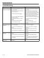
TROUBLESHOOTING
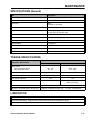
SPECIFICATIONS (GENERAL)
TORQUE SPECIFICATIONS
LUBRICATION
TORO
®
Snow Commander
Service Manual
ABOUT THIS MANUAL
This service manual was written expressly for Toro servicing dealers. The Toro Company
has made every effort to make the information in this manual complete and correct.
This manual was written with the assumption that the reader has basic mechanical
knowledge and skills. This book contains material covering the Toro Snow Commander
models produced in 2001 and 2002, and may be specified for use on products built after
2002 that are similar in design.
We hope you find this manual a valuable addition to your service shop. If you have
questions or comments regarding this manual, please contact us at the following address:
The Toro Company
Consumer Service Department
8111 Lyndale Avenue South
Bloomington, MN 55420-1196
The Toro Company reserves the right to change product specifications or this manual
without notice.
Copyright© All Rights Reserved
©2001 The Toro Company
TABLE OF CONTENTS
GENERAL INFORMATION
Introduction . . . . . . . . . . . . . . . . . . . . . . . . . . . . . . . . . . . . . . . . . . . . . . . . . . . . . . . . . . .1 - 1
Engine . . . . . . . . . . . . . . . . . . . . . . . . . . . . . . . . . . . . . . . . . . . . . . . . . . . . . . . . . . . . . . .1 - 1
Identification and Ordering . . . . . . . . . . . . . . . . . . . . . . . . . . . . . . . . . . . . . . . . . . . . . . .1 - 2
General Safety Instructions (Reproduced from Operator’s Manual) . . . . . . . . . . . . . . . .1 - 2
Safety . . . . . . . . . . . . . . . . . . . . . . . . . . . . . . . . . . . . . . . . . . . . . . . . . . . . . . . . . . . . . . .1 - 3
Safe Operating Practices . . . . . . . . . . . . . . . . . . . . . . . . . . . . . . . . . . . . . . . . . . . . . .1 - 3
Training . . . . . . . . . . . . . . . . . . . . . . . . . . . . . . . . . . . . . . . . . . . . . . . . . . . . . . . . . . .1 - 3
Preparation . . . . . . . . . . . . . . . . . . . . . . . . . . . . . . . . . . . . . . . . . . . . . . . . . . . . . . . . .1 - 3
Operation . . . . . . . . . . . . . . . . . . . . . . . . . . . . . . . . . . . . . . . . . . . . . . . . . . . . . . . . . .1 - 3
Maintenance and Storage . . . . . . . . . . . . . . . . . . . . . . . . . . . . . . . . . . . . . . . . . . . . .1 - 4
Toro Snowthrower Safety . . . . . . . . . . . . . . . . . . . . . . . . . . . . . . . . . . . . . . . . . . . . . . . .1 - 4
Safety and Instruction Decals . . . . . . . . . . . . . . . . . . . . . . . . . . . . . . . . . . . . . . . . . .1 - 5
Fuel and Oil Requirements . . . . . . . . . . . . . . . . . . . . . . . . . . . . . . . . . . . . . . . . . . . . . . .1 - 6
Mixing Gasoline and Oil . . . . . . . . . . . . . . . . . . . . . . . . . . . . . . . . . . . . . . . . . . . . . . .1 - 6
Filling the Fuel Tank . . . . . . . . . . . . . . . . . . . . . . . . . . . . . . . . . . . . . . . . . . . . . . . . . .1 - 7
Off-Season Storage . . . . . . . . . . . . . . . . . . . . . . . . . . . . . . . . . . . . . . . . . . . . . . . . . . . . .1 - 7
Emptying the Fuel Tank . . . . . . . . . . . . . . . . . . . . . . . . . . . . . . . . . . . . . . . . . . . . . . .1 - 7
Storage . . . . . . . . . . . . . . . . . . . . . . . . . . . . . . . . . . . . . . . . . . . . . . . . . . . . . . . . . . . .1 - 7
Preparing the Fuel System . . . . . . . . . . . . . . . . . . . . . . . . . . . . . . . . . . . . . . . . . . . . .1 - 8
Preparing the Engine . . . . . . . . . . . . . . . . . . . . . . . . . . . . . . . . . . . . . . . . . . . . . . . . .1 - 8
Preparing the Snowthrower . . . . . . . . . . . . . . . . . . . . . . . . . . . . . . . . . . . . . . . . . . . .1 - 8
CONTROLS LOCATION & OPERATION
Operating Controls . . . . . . . . . . . . . . . . . . . . . . . . . . . . . . . . . . . . . . . . . . . . . . . . . . . . .2 - 1
Starting the Engine . . . . . . . . . . . . . . . . . . . . . . . . . . . . . . . . . . . . . . . . . . . . . . . . . . . . .2 - 1
Stopping the Engine . . . . . . . . . . . . . . . . . . . . . . . . . . . . . . . . . . . . . . . . . . . . . . . . . . . .2 - 1
Starting the Rotor Blades . . . . . . . . . . . . . . . . . . . . . . . . . . . . . . . . . . . . . . . . . . . . . . . .2 - 2
Stopping the Rotor Blades . . . . . . . . . . . . . . . . . . . . . . . . . . . . . . . . . . . . . . . . . . . . . . . .2 - 2
Starting the Traction Drive . . . . . . . . . . . . . . . . . . . . . . . . . . . . . . . . . . . . . . . . . . . . . . . .2 - 2
Stopping the Traction Drive . . . . . . . . . . . . . . . . . . . . . . . . . . . . . . . . . . . . . . . . . . . . . . .2 - 2
Snow Commander Service Manual
i
TABLE OF CONTENTS
CONTROLS LOCATION & OPERATION (cont’d)
Adjusting the Discharge Chute . . . . . . . . . . . . . . . . . . . . . . . . . . . . . . . . . . . . . . . . . . . .
Chute Handle . . . . . . . . . . . . . . . . . . . . . . . . . . . . . . . . . . . . . . . . . . . . . . . . . . . . . .
Chute Crank . . . . . . . . . . . . . . . . . . . . . . . . . . . . . . . . . . . . . . . . . . . . . . . . . . . . . . .
Upper Shroud Removal . . . . . . . . . . . . . . . . . . . . . . . . . . . . . . . . . . . . . . . . . . . . . .
Snow Commander Chute Handle System . . . . . . . . . . . . . . . . . . . . . . . . . . . . . . . .
Chute Crank System . . . . . . . . . . . . . . . . . . . . . . . . . . . . . . . . . . . . . . . . . . . . . . . . .
2-2
2-2
2-3
2-3
2-3
2-4
Gear Lash Adjustment . . . . . . . . . . . . . . . . . . . . . . . . . . . . . . . . . . . . . . . . . . . . . . . . . . 2 - 5
Gear Assembly Repair . . . . . . . . . . . . . . . . . . . . . . . . . . . . . . . . . . . . . . . . . . . . . . . 2 - 5
ENGINE REMOVAL / INSTALLATION
Assembly . . . . . . . . . . . . . . . . . . . . . . . . . . . . . . . . . . . . . . . . . . . . . . . . . . . . . . . . . 3 - 4
Recoil Starter Access . . . . . . . . . . . . . . . . . . . . . . . . . . . . . . . . . . . . . . . . . . . . . . . . 3 - 5
Assembly . . . . . . . . . . . . . . . . . . . . . . . . . . . . . . . . . . . . . . . . . . . . . . . . . . . . . . . . . 3 - 6
DRIVE SYSTEM
Operation . . . . . . . . . . . . . . . . . . . . . . . . . . . . . . . . . . . . . . . . . . . . . . . . . . . . . . . . .
Drive System Disassembly . . . . . . . . . . . . . . . . . . . . . . . . . . . . . . . . . . . . . . . . . . . .
Drive System Assembly . . . . . . . . . . . . . . . . . . . . . . . . . . . . . . . . . . . . . . . . . . . . . .
Rotor Bearing Replacement . . . . . . . . . . . . . . . . . . . . . . . . . . . . . . . . . . . . . . . . . . .
Assembly . . . . . . . . . . . . . . . . . . . . . . . . . . . . . . . . . . . . . . . . . . . . . . . . . . . . . . . . .
Rotor Cable Replacement . . . . . . . . . . . . . . . . . . . . . . . . . . . . . . . . . . . . . . . . . . . . .
4-1
4-2
4-4
4-5
4-6
4-6
ELECTRIC START SYSTEM
Operation . . . . . . . . . . . . . . . . . . . . . . . . . . . . . . . . . . . . . . . . . . . . . . . . . . . . . . . . . . . . 5 - 1
Troubleshooting . . . . . . . . . . . . . . . . . . . . . . . . . . . . . . . . . . . . . . . . . . . . . . . . . . . . 5 - 1
System Disassembly . . . . . . . . . . . . . . . . . . . . . . . . . . . . . . . . . . . . . . . . . . . . . . . . . 5 - 1
Assembly . . . . . . . . . . . . . . . . . . . . . . . . . . . . . . . . . . . . . . . . . . . . . . . . . . . . . . . . . . . .
Switch Box Repair . . . . . . . . . . . . . . . . . . . . . . . . . . . . . . . . . . . . . . . . . . . . . . . . . . .
Power Plug . . . . . . . . . . . . . . . . . . . . . . . . . . . . . . . . . . . . . . . . . . . . . . . . . . . . . . . .
Plug Terminal . . . . . . . . . . . . . . . . . . . . . . . . . . . . . . . . . . . . . . . . . . . . . . . . . . . . . .
Switch . . . . . . . . . . . . . . . . . . . . . . . . . . . . . . . . . . . . . . . . . . . . . . . . . . . . . . . . . . . .
Motor Testing . . . . . . . . . . . . . . . . . . . . . . . . . . . . . . . . . . . . . . . . . . . . . . . . . . . . . .
5-2
5-3
5-3
5-3
5-4
5-4
Assembly . . . . . . . . . . . . . . . . . . . . . . . . . . . . . . . . . . . . . . . . . . . . . . . . . . . . . . . . . . . . 5 - 4
Starter Pinion Replacement . . . . . . . . . . . . . . . . . . . . . . . . . . . . . . . . . . . . . . . . . . . 5 - 5
Assembly . . . . . . . . . . . . . . . . . . . . . . . . . . . . . . . . . . . . . . . . . . . . . . . . . . . . . . . . . . . . 5 - 6
CHASSIS
Wheels and Tires . . . . . . . . . . . . . . . . . . . . . . . . . . . . . . . . . . . . . . . . . . . . . . . . . . . 6 - 1
Tilt Mechanism/Frame . . . . . . . . . . . . . . . . . . . . . . . . . . . . . . . . . . . . . . . . . . . . . . . 6 - 1
Pivot Cable Replacement . . . . . . . . . . . . . . . . . . . . . . . . . . . . . . . . . . . . . . . . . . . . . 6 - 2
ii
Snow Commander Service Manual
TABLE OF CONTENTS
MAINTENANCE
Recommended Maintenance Schedule . . . . . . . . . . . . . . . . . . . . . . . . . . . . . . . . . . . . . .7 - 1
Rotor Control Cable . . . . . . . . . . . . . . . . . . . . . . . . . . . . . . . . . . . . . . . . . . . . . . . . . . . . .7 - 1
Checking the Rotor Control Cable . . . . . . . . . . . . . . . . . . . . . . . . . . . . . . . . . . . . . . .7 - 1
Adjusting the Rotor Control Cable . . . . . . . . . . . . . . . . . . . . . . . . . . . . . . . . . . . . . . .7 - 2
Adjusting the Pivot Cable . . . . . . . . . . . . . . . . . . . . . . . . . . . . . . . . . . . . . . . . . . . . . . . .7 - 3
Checking the Pivot Cable . . . . . . . . . . . . . . . . . . . . . . . . . . . . . . . . . . . . . . . . . . . . . .7 - 3
Adjusting the Pivot Cable . . . . . . . . . . . . . . . . . . . . . . . . . . . . . . . . . . . . . . . . . . . . . .7 - 4
Replacing the Rotor Blades . . . . . . . . . . . . . . . . . . . . . . . . . . . . . . . . . . . . . . . . . . . . . . .7 - 4
Removing the Old Rotor Blades . . . . . . . . . . . . . . . . . . . . . . . . . . . . . . . . . . . . . . . . .7 - 4
Installing the New Rotor Blades . . . . . . . . . . . . . . . . . . . . . . . . . . . . . . . . . . . . . . . . .7 - 5
Replacing the Scraper . . . . . . . . . . . . . . . . . . . . . . . . . . . . . . . . . . . . . . . . . . . . . . . . . . .7 - 6
Replacing the Spark Plug . . . . . . . . . . . . . . . . . . . . . . . . . . . . . . . . . . . . . . . . . . . . . . . .7 - 6
Replacing the Drive Belt . . . . . . . . . . . . . . . . . . . . . . . . . . . . . . . . . . . . . . . . . . . . . . . . .7 - 7
Checking the Tire Pressure . . . . . . . . . . . . . . . . . . . . . . . . . . . . . . . . . . . . . . . . . . . . . . .7 - 9
Troubleshooting . . . . . . . . . . . . . . . . . . . . . . . . . . . . . . . . . . . . . . . . . . . . . . . . . . . . . . . .7 - 9
Specifications (General) . . . . . . . . . . . . . . . . . . . . . . . . . . . . . . . . . . . . . . . . . . . . . . . .7 - 11
Torque Specifications . . . . . . . . . . . . . . . . . . . . . . . . . . . . . . . . . . . . . . . . . . . . . . . . . . 7 - 11
Lubrication . . . . . . . . . . . . . . . . . . . . . . . . . . . . . . . . . . . . . . . . . . . . . . . . . . . . . . . . . . . 7 - 11
Snow Commander Service Manual
iii
THIS PAGE INTENTIONALLY LEFT BLANK
iv
Snow Commander Service Manual
GENERAL INFORMATION
Introduction
Read this manual carefully to learn how to operate and
maintain your product properly. The information in this
manual can help you and others avoid injury and
product damage. Although Toro designs and produces
safe products, you are responsible for operating the
product properly and safely.
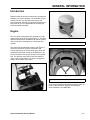
Engine
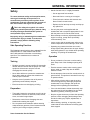
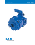
The Toro Snow Commanders are powered by a high
output version of the R tek engine (Figure 1). The main
difference between the standard R tek and the version
used on the Snow Commander is in the piston and
cylinder.
A
Figure 2
DSC-0037
(A) Ports
The piston has two additional square ports (Figure 2),
which line up with two grooves machined in the
cylinder wall (Figure 3). As the piston goes down and
compresses the fuel/air charge in the crankcase, the
ports in the piston uncover the grooves in the cylinder
wall. This provides extra area for the fuel charge to
move to the firing chamber. The result is a larger fuel
charge, which makes more power.
A
Figure 3
DSC-0032
(A) Grooves
All service procedures and techniques are the same as
those on the other R tek engines. See E Engine
Service Manual, Form #492-0647.
Figure 1
Snow Commander Service Manual
DSC-0138
1-1
GENERAL INFORMATION
Identification and Ordering
Be prepared to supply the complete model and serial
number and contact us at the following address:
Whenever you need service, genuine Toro parts, or
additional information, contact an Authorized Service
Dealer or Toro Customer Service and have the model
and serial numbers of your product ready. Figure 1
illustrates the location of the model and serial numbers
on the product.
The Toro Company
8111 Lyndale Ave. S.
Bloomington, MN 55420
Phone: 1-800-348-2424
Follow the instructions to contact the parts dept. The
parts department staff will be happy to assist you in
obtaining replacement manuals.
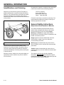
General Safety Instructions
(Reproduced from Operator’s Manual)
This manual identifies potential hazards and has
special safety messages that help you and others
avoid personal injury and even death. Danger,
Warning, and Caution are signal words used to
identify the level of hazard. However, regardless of the
hazard, be extremely careful.
Figure 4
m-5045
(A) Location of the model and serial numbers
Provide the full model and serial number to any
Authorized Toro Service Dealer. They will be able to
look up the part number and provide you with price
quotes and availability. The factory does not sell parts
or products direct.
Should you wish to obtain your own parts catalog or a
replacement owners manual, they can be obtained
from the factory.
1-2
Danger signals an extreme hazard that will cause
serious injury or death if you do not follow the
recommended precautions.
Warning signals a hazard that may cause serious
injury or death if you do not follow the recommended
precautions.
Caution signals a hazard that may cause minor or
moderate injury if you do not follow the recommended
precautions.
This manual uses two other words to highlight
information. Important calls attention to special
mechanical information and Note: emphasizes general
information worthy of special attention.
Snow Commander Service Manual
GENERAL INFORMATION
Safety
•
Handle fuel with care; it is highly flammable.
– Use an approved fuel container.
– Never add fuel to a running or hot engine.
To ensure maximum safety and best performance,
and to gain knowledge of the product, it is
essential that you and any other operator of the
snowthrower read and understand the contents of
this manual before the engine is ever started.
This is the safety alert symbol. It is used to
alert you to potential personal injury hazards. Obey
all safety messages that follow this symbol to
avoid possible injury or death.
– Fill the fuel tank outdoors with extreme care.
Never fill the fuel tank indoors.
– Replace the fuel tank cap securely and wipe up
any spilled fuel.
•
Use only the power cord supplied with the
snowthrower and a receptacle appropriate for use
with the power cord for electric-start motors.
•
Never attempt to make any adjustments while the
engine is running, except where specifically
recommended by Toro.
•
Let the engine and the snowthrower adjust to the
outdoor temperature before starting to clear snow.
Safe Operating Practices
•
The following instructions have been adapted from the
ANSI/OPEI B71.3–1995 standard and the ISO
8437:1989 standard. Information or terminology
specific to Toro snowthrowers is enclosed in
parenthesis.
Operating any powered machine can result in
foreign objects being thrown into the eyes. Always
wear safety glasses or eye shields while operating,
adjusting, or repairing the snowthrower.
Operation
Training
•
Do not put hands or feet near or under rotating
parts. Keep clear of the discharge opening at all
times.
•
Exercise extreme caution when crossing gravel
drives, walks, or roads. Stay alert for hidden
hazards or traffic.
Improperly using or maintaining this snowthrower
could result in injury or death. To reduce this
potential, comply with the following safety
instructions.
•
Read the operator’s manual carefully. Be thoroughly
familiar with the controls and the proper use of the
equipment. Know how to stop the unit and
disengage the controls quickly.
•
Never allow children to operate the snowthrower.
Never allow adults to operate the snowthrower
without proper instruction.
•
Do not attempt to clear snow from a crushed-rock or
gravel surface. This product is intended for use only
on paved surfaces.
•
Keep the area of operation clear of all persons
(particularly small children) and pets.
•
•
Exercise caution to avoid slipping or falling.
After striking a foreign object, stop the engine,
remove the ignition key, thoroughly inspect the
snowthrower for any damage, and repair the
damage before operating the snowthrower.
•
If the unit should start to vibrate abnormally, stop
the engine and check immediately for the cause.
Vibration is generally a warning of trouble.
•
Stop the engine whenever you leave the operating
position, before unclogging the discharge chute,
and when making any repairs, adjustments, or
inspections.
•
When cleaning, repairing, or inspecting, make
certain that the rotor blades and all moving parts
have stopped.
Preparation
•
Thoroughly inspect the area where you will use the
snowthrower. Remove all doormats, sleds, boards,
wires, and other foreign objects.
•
Release the control bar to disengage the rotor
blades before starting the engine.
•
Do not operate the snowthrower without wearing
adequate winter garments. Wear footwear that will
improve your footing on slippery surfaces.
Snow Commander Service Manual
1-3
GENERAL INFORMATION
•
Do not run the engine indoors, except when starting
it and for moving the snowthrower in or out of the
building. Open the outside doors; exhaust fumes
are dangerous.
•
Do not clear snow across the face of slopes.
Exercise extreme caution when changing direction
on slopes. Do not attempt to clear steep slopes.
•
Never operate the snowthrower without proper
guards, plates, or other safety protective devices in
place.
•
Never operate the snowthrower near glass
enclosures, automobiles, window wells, and dropoffs without properly adjusting the snow discharge
angle. Keep children and pets away.
Toro Snowthrower Safety
The following list contains safety information specific to
Toro products or other safety information that you must
know.
•
Rotating rotor blades can injure fingers or hands.
Stay behind the handles and away from the
discharge opening while operating the snowthrower.
Keep your face, hands, feet, and any other part of
your body or clothing away from moving or rotating
parts.
•
Before adjusting, cleaning, repairing, and inspecting
the snowthrower, and before unclogging the
discharge chute, stop the engine, remove the key,
and wait for all moving parts to stop.
•
Do not overload the machine capacity by attempting
to clear snow at too fast a rate.
•
Look behind and use care when backing up with the
snowthrower.
•
Use a stick, not your hands, to remove obstructions
from the discharge chute.
•
Never direct the discharge at bystanders or allow
anyone in front of the unit.
•
•
Never operate the snowthrower without good
visibility or light. Always be sure of your footing, and
keep a firm hold on the handle. Walk; never run.
Before leaving the operating position, stop the
engine, remove the key, and wait for all moving
parts to stop.
•
Do not wear loose-fitting clothing that could get
caught in moving parts.
•
If a shield, safety device, or decal is damaged,
illegible, or lost, repair or replace it before beginning
operation.
•
Also, tighten any loose fasteners.
•
Do not smoke while handling gasoline.
•
Do not use the snowthrower on a roof.
•
Do not touch the engine while it is running or soon
after it has stopped because the engine may be hot
enough to cause a burn.
•
Perform only those maintenance instructions
described in this manual. Before performing any
maintenance, service, or adjustment, stop the
engine, remove the key. If major repairs are ever
needed, contact your Authorized Service Dealer.
•
Do not change the governor settings on the engine.
•
When storing the snowthrower for more than 30
days, drain the fuel from the fuel tank to prevent a
potential hazard. Store fuel in an approved fuel
container. Remove the key from the ignition switch
before storing the snowthrower.
Maintenance and Storage
•
Check all fasteners at frequent intervals for proper
tightness to be sure that the equipment is in safe
working condition.
•
Never store the machine with fuel in the fuel tank
inside a building where ignition sources are present,
such as hot water and space heaters and clothes
dryers. Allow the engine to cool before storing in
any enclosure.
•
Always refer to this operator’s manual for important
details if the snowthrower is to be stored for an
extended period.
•
Maintain or replace safety and instruction labels
when necessary.
To ensure the best performance and safety, purchase
only genuine Toro replacement parts and accessories.
1-4
Snow Commander Service Manual
GENERAL INFORMATION
Safety and Instruction Decals
Safety decals and instructions are easily visible to the operator and are located near any area of
potential danger. Replace any decal that is damaged or lost.
61-4790 (Electric-start model only)
104-4106 (Recoil-start model only)
104-0863 (Electric-start model only)
104-4125
104-0874
104-4135
104-2767
104-2775
Snow Commander Service Manual
1-5
GENERAL INFORMATION
Fuel and Oil Requirements
Mixing Gasoline and Oil
This Toro snowthrower is powered by a two-cycle
engine that requires a 50:1 gasoline-to-oil mixture.
Use only clean, unleaded gasoline no more than 30
days old and with an octane rating of 87 or higher.
Using unleaded gasoline reduces combustion chamber
deposits and promotes longer spark plug life.
Engines certified to comply with U.S. EPA emission
regulations for ULGE engines are certified to operate
on a mixture of regular unleaded gasoline and oil, include
the following emission control system(s): EM and TWC (if
equipped), and do not include any user-adjustable features.
Important Do not use methanol, gasoline
containing methanol, gasohol containing more than
10% ethanol, premium gasoline, or white gas. Using
these fuels can damage the fuel system.
Important Do not use an automotive oil (such as
SAE 30 or 10W30), a two-cycle oil that is not NMMA
TCW-certified, or a fuel mixed at the wrong gasoline-tooil ratio. This can cause engine damage not covered
under the Toro warranty.
DANGER
In certain conditions, gasoline is extremely
flammable and highly explosive. A fire or
explosion from gasoline an burn you and others
and cause property damage.
•
•
•
•
•
1-6
Fill the fuel tank outdoors, in an open area,
and when the engine is cold. Wipe up any
gasoline that spills.
Do not fill the fuel tank completely full. Add
gasoline to the fuel tank until the level is 1/4
to 1/2 in. (6 to 13mm) below the bottom of the
filler neck. This empty space in the tank
allows the gasoline to expand.
Never smoke when handling gasoline, and
stay away from an open flame or where a
spark may ignite gasoline fumes.
Store gasoline in an approved fuel container
and keep it out of the reach of children.
Never buy more than a 30-day supply of
gasoline.
DANGER
When fueling under certain circumstances, a
static charge can develop igniting the gasoline.
A fire or explosion from gasoline can burn you
and other and damage property.
•
•
•
•
•
Always place gasoline containers on the
ground and away from your vehicle before
filling.
Do not fill gasoline containers inside a
vehicle or on a truck or trailer bed because
interior carpets or plastic truck bed liners
may insulate the container and slow the loss
of any static charge.
When practical, remove gas-powered
equipment from the truck or trailer and refuel
the equipment with its wheels on the ground.
If this is not possible, then refuel such
equipment on a truck or trailer from a
portable container, not from a gasoline
dispenser nozzle.
If you must use a gasoline dispenser nozzle,
keep the nozzle in contact with the rim of the
fuel tank or container opening at all times
until fueling is complete.
Note: Use a fuel stabilizer/conditioner for all Toro
gasoline-powered products during operation and
storage. A fuel stabilizer/conditioner cleans the engine
during operation and prevents gum-like varnish
deposits from forming in the engine during storage. A
fuel stabilizer/conditioner works best when you mix it
with fresh gasoline. If you use Toro 50:1 2-Cycle Oil
(Fuel Stabilizer Added), you do not need to add a fuel
stabilizer/conditioner.
Important Do not use fuel additives except a fuel
stabilizer during storage. Do not use fuel stabilizers
with an alcohol base, such as ethanol, methanol, or
isopropanol.
1.
Pour a half gallon (1.9 liters) of fresh, unleaded
gasoline into an approved fuel container.
Note: Do not mix gasoline and oil in the fuel tank. Oil at
room temperature mixes easier and more thoroughly
than cold oil. Oil below 32°F (0°C) requires additional
mixing.
Snow Commander Service Manual
GENERAL INFORMATION
2.
Add the full amount of Toro 50:1 2-Cycle Oil (Fuel
Stabilizer Added) or an equivalent high grade,
NMMA TCW-certified two-cycle oil to the gasoline
according to the chart below:
50:1 Gasoline-to Oil Ration Mixing Chart
Gasoline
Oil
1 gallon (4 liters)
2.6 ounces (80 ml)
2 gallons (8 liters)
5.2 ounces (160 ml)
5 gallons (20 liters)
13 ounces (400 ml)
3.
Install the cap on the fuel container.
4.
Shake the container to mix the gasoline and oil
thoroughly.
5.
Slowly remove the cap and add the remaining
amount of gasoline.
Filling the Fuel Tank
Important Do not overfill the fuel tank. The
gasoline-and-oil mixture must have room to expand.
1.
2.
3.
Clean around the fuel tank cap; do not allow snow
or water to enter the fuel tank.
Remove the fuel tank cap and fill the fuel tank with
the gasoline-and-oil mixture until the level is 1/4 to
1/2 in. (6 to 13mm) below the bottom of the filler
neck. Do not fill into the filler neck.
Install the fuel tank cap securely and wipe up any
spilled fuel.
Off-Season Storage
Emptying the Fuel Tank
1.
Stop the engine and wait for all moving parts to
stop.
Snow Commander Service Manual
2.
Remove the key from the switch.
DANGER
Gasoline is highly flammable; it can ignite and
cause serious personal injury.
•
Drain gasoline outdoors.
•
Drain gasoline from a cold engine only.
•
Wipe up any gasoline that may have spilled.
•
Do not drain gasoline near any open flame or
where gasoline fumes may be ignited by a
spark.
•
Do not smoke a cigar, a cigarette, or a pipe
when handling gasoline.
3.
Remove the fuel tank cap and use a hand pump to
pump the fuel into an approved fuel container.
4.
Start the engine and allow it to run until it stops.
Repeat this step two more times to ensure that the
fuel tank and the carburetor are empty.
Storage
Important Store the snowthrower in its operating
position and on its wheels. Storing the snowthrower on
its front housing may cause hard starting.
WARNING
Gasoline fumes are highly flammable, explosive,
and dangerous if inhaled. If you store the
product in an area with an open flame, the
gasoline fumes may ignite and cause an
explosion.
Do not store the snowthrower in a house (living
area), basement, or any other area where
ignition sources may be present, such as hot
water and space heaters, clothes dryers,
furnaces, and other like appliances.
1-7
GENERAL INFORMATION
Preparing the Fuel System
Preparing the Snowthrower
1.
1.
Tighten all loose screws, bolts, and locknuts.
Repair or replace any damaged parts.
2.
Clean the snowthrower thoroughly.
3.
Cover the snowthrower and store it in a clean, dry
place out of the reach of children. Allow the engine
to cool before storing it in any enclosure.
Add a fuel stabilizer/conditioner to the fuel in the
fuel tank as directed.
NOTE: If you use Toro 50:1 2-Cycle (Fuel Stabilizer
Added), you do not need to add a fuel stabilizer/
conditioner.
2.
Run the engine for five minutes to distribute the
conditioned fuel through the fuel system.
3.
Stop the engine, allow it to cool.
4.
Use a hand pump to pump the fuel from the fuel
tank into an approved fuel container, or run the
engine until it stops.
5.
Start the engine and run it until it stops.
6.
Choke or prime the engine, start it a third time,
and run the engine until it will not start.
7.
Dispose of unused fuel properly. Recycle it
according to local codes, or use it in your
automobile.
Note: Do not store stabilized fuel for more than 90
days.
Preparing the Engine
Follow this procedure to prevent cylinder bore
corrosion by closing both the intake and exhaust ports
of the engine.
1.
Slowly pull the recoil starter until you feel
resistance due to compression pressure, then
stop.
2.
Release the starter tension gradually by allowing
the rope to go back slowly to prevent the engine
from reversing due to compression pressure.
1-8
Snow Commander Service Manual
CONTROLS LOCATION & OPERATION
Note: Do not use the choke or the primer when
starting a warm engine.
NOTE: Determine the left and right sides of the
machine from normal operating position.
4.
Operating Controls
Start the engine by doing the following:
For a recoil starter: Hold the snowthrower handle
with one hand and pull the recoil starter vigorously
with the other hand.
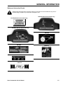
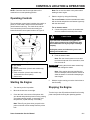
The snowthrower control panel contains a key switch, a
primer, a recoil starter, and an electric-start button
(electric-start model only). The choke lever and the
cord connection (for the electric-start model) are
located below the control panel as show in Figure 5.
For an electric starter:
A. Connect the power cord to the snowthrower
and to a standard household power outlet.
CAUTION
If you leave the snowthrower plugged into a
power outlet, someone can inadvertently start
the snowthrower and injure people or damage
property.
Unplug the power cord whenever you are not
starting the snowthrower.
B. Push the starter button.
Figure 5
Note: Run the electric starter no more than
ten times at intervals of five seconds on, then
five seconds off.
m-5067
(A)
(B)
(C)
(D)
(E)
Key switch
Primer
Electric-start button (electric-start model only)
Recoil start
Cord connection (electric-start model only;
underneath the control panel)
(F) Choke lever
Starting the Engine
1.
Turn the key to the On position.
2.
Move the choke lever to the right.
3.
Cover the hole in the center of the primer with
your thumb and push the primer in twice, pausing
a moment between pushes. In extremely cold
temperatures, repeat this step if necessary.
Important Running the electric starter extensively
can overheat and damage the starter.
Note: If the engine does not start after this
series of attempts, wait at least 40 minutes to
allow the starter to cool before attempting to
start it again.
5.
With the engine running, move the choke lever to
the left slowly.
Stopping the Engine
Turn the key to the Off position and wait for all moving
parts to stop before leaving the operating position.
Note: Take off your glove when you push in the
primer so that air cannot escape from the primer
hole.
Snow Commander Service Manual
2-1
CONTROLS LOCATION & OPERATION
Starting the Rotor Blades
Adjusting the Discharge Chute
To start the rotor blades, squeeze the control bar
toward the handle until the snowthrower begins to
pivot.
Chute Handle
Stopping the Rotor Blades
To stop the rotor blades, release the control bar.
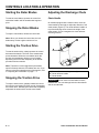
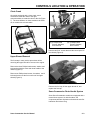
On models equipped with a manual chute, move the
chute handle left and right to adjust the direction of the
snow stream (Figure 6). The chute deflector handle on
top of the discharge chute controls the height of the
snow stream. Do not overtighten the chute deflector
mounting locknuts.
Note: When you release the control bar, the rotor
blades stop, but the engine continues to run.
Starting the Traction Drive
To start the traction drive, slowly squeeze the control
bar toward the handle. The front of the snowthrower
pivots downward. When the rotor blades touch the
ground, the snowthrower begins to move forward.
Squeezing the control bar completely to the handle
provides maximum traction.
Note: The traction is most aggressive (the traction
speed is fastest) when the rotor blades are new. If you
want to reduce the aggressiveness of the traction, refer
to "Adjusting the Pivot Cable" on page 7 - 3.
Stopping the Traction Drive
To stop the traction drive, partially release the control
bar until the rotor blades lift off the ground, disengaging
the traction drive. Releasing the control bar completely
stops both the traction drive and the rotor blades.
2-2
Figure 6
m-5052
(A) Chute deflector mounting locknut (2)
(B) Chute deflector handle
(C) Chute handle
Important Do not use the chute handle to lift the
snowthrower. This can damage both the chute handle
and the snowthrower.
Snow Commander Service Manual
CONTROLS LOCATION & OPERATION
Chute Crank
On models equipped with a chute crank, crank
clockwise to rotate the chute to the right,
counterclockwise to rotate the chute to the left (Figure
7). The chute deflector on these models is the same
as on models with a chute handle.
B A
A
Figure 8
(A) 2 Phillips Head
Screws, Washers,
and Locknuts
Figure 7
0621-0073
3428-0216
(B) 3 Phillips Head
Screws, Washers,
and Locknuts
Remove two 5/16” screws that hold the control panel to
the chassis (Figure 9).
Upper Shroud Removal
The first step in many service procedures will be
removing the upper shroud for access to the engine.
Remove the three Phillips head screws, washer, and
locknuts that hold the chute and chute handle to the
chassis (Figure 8).
Remove two Phillips head screws, 4 washers, and 2
locknuts that secure the front corners of the upper
shroud (Figure 8).
Figure 9
3428-0217
Remove the fuel cap, lift the upper shroud off, and
replace the fuel cap.
Snow Commander Chute Handle System
Some Snow Commander models were equipped with a
manual chute system. As with the others, the
component parts are all plastic to eliminate the need for
lubrication and reduce icing.
Snow Commander Service Manual
2-3
CONTROLS LOCATION & OPERATION
On this version, the discharge chute attaches to the
handle and chute ring. Three Phillips head bolts, nuts,
and washers connect the parts. Below the upper
shroud is the balance of the chute components.
A
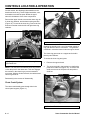
Remove the upper shroud to access the chute ring, the
2 chute ring retainers, and the detent spring and arm
(Figure 10). To remove the chute ring, remove the four
bolts and nuts that retain the left and right chute ring
retainers.
C
Figure 11
3428-0082
(A) Control Handle Support
Rotating the handle turns a set of gears that engage a
ring gear that the chute is mounted to. The gears are
contained in a bracket located under the upper shroud.
B
A
The chute ring gear rests on a support and is held in
place by two retainers.
Figure 10
(A) Spring
(B) Detent Arm
1854-40
(C) Retainer Mounting Bolts
NOTE: The rear bolt in the left hand chute ring retainer
is also the pivot for the detent arm. This arm engages
the notches in the chute ring to prevent unwanted
movement. With the 4 bolts removed, the retainers and
chute ring will lift off.
To access the chute ring and gears:
1.
Remove the upper shroud.
2.
The gears are held in the bracket by a shaft with a
push nut on either end (Figure 12). To remove the
shaft, remove one of the push nuts and pull the
shaft out.
A
Reassembly is the reverse of disassembly.
Chute Crank System
The chute crank handle goes through hole in the
control panel support (Figure 11).
Figure 12
1854-19
(A) Shaft and Push Nut
2-4
Snow Commander Service Manual
CONTROLS LOCATION & OPERATION
3.
To reassemble, reverse the process.
NOTE: When installing the chute, the rounded
heads of the Phillips head screws must be on the
inside of the chute. The smooth head prevents
snow from building up on the bolt head.
A
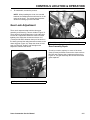
Gear Lash Adjustment
There are 4 capscrews that hold the chute gear
assembly to the housing. Two are visible in Figure 13.
There will be 2 identical capscrews on the other side.
Loosen all 4 capscrews. Rotate the chute to find the
tightest point. Adjust the clearance so that a 1/16”
(1.6mm) drill bit will fit between the top of the tooth on
the worm gear and the valley between two teeth on the
chute ring gear (Figure 14). Grasp the chute rod and
push it to the front. Hold the rod and tighten the
capscrews. Remove the drill bit.
B
Figure 14
(A) 1/1” (1.6mm) Drill Bit
0621-0076-A
(B) Chute Ring
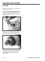
Gear Assembly Repair
Should you need to replace 1 or more of the chute
gears, proceed as follows. Remove the chute rod from
the face gear. Remove the 4 capscrews referred to in
Figure 13. The gear assembly can be lifted out and the
gears replaced.
A
Figure 13
0621-0077
(A) Capscrews
Snow Commander Service Manual
2-5
THIS PAGE INTENTIONALLY LEFT BLANK
2-6
Snow Commander Service Manual
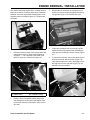
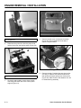
ENGINE REMOVAL / INSTALLATION
The Snow Commander engine sits in a cradle which is
bolted to the frame. It is best to remove the cradle and
separate it from the engine after removing them as an
assembly from the chassis (Figure 15). The steps are
as follows:
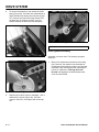
3.
Remove the two screws in the carburetor cover,
slide the cover to the left to disengage the tabs on
the right side (Figure 17). Remove the cover.
Figure 17
DSC-0138
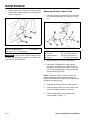
4.
Remove fuel from the tank. Remove the chute and
upper shroud; refer to “Upper Shroud Removal”
on page 2 - 3. Tie a slip knot in the starter rope
where it comes out of the recoil (Figure 16).
Temporarily clamp the fuel line and slip it off the
carburetor fitting. Be prepared with something to
catch any fuel remaining in the line or filter (Figure
16).
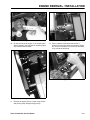
5.
To remove the fuel tank, remove the two bolts and
locknuts on the left side of the tank (Figure 18).
Then slide the tank to the left to disengage it from
the support pin on the right side (Figure 19). Lift
the tank out of the machine.
Figure 15
1.
DSC-0181
A
B
Figure 16
(A) Starter Rope
2.
3428-0222
(B) Carburetor Fitting
Figure 18
3428-0223
Untie the knot in the starter handle and pull the
rope through the control panel and support. Roll
up the rope and secure with tape to keep it out of
your way.
Snow Commander Service Manual
3-1
ENGINE REMOVAL / INSTALLATION
A
Figure 19
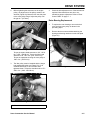
8.
(A) Support Pin
6.
Figure 21
3428-0227
Disconnect the primer line from the primer bulb
and the wires from the ignition switch (Figure 20).
3428-0228
Remove the belt cover (3 bolts and 2 screws)
(Figure 22). Some models were built with a
diamond shaped washer.
A
Figure 22
Figure 20
DSC-0138
(A) Primer and Ignition Switch
7.
3-2
On electric start models, remove three screws
connecting the switch box to the control panel
support (Figure 21).
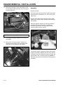
9.
3428-0229-2
Remove the belt. Push the idler arm down as far
as it will go. Measure the distance between the
idler pulley and engine pulley at its closest point
(Figure 23). Make a note of this distance as it will
be needed during assembly.
Snow Commander Service Manual
ENGINE REMOVAL / INSTALLATION
Figure 23
3428-0232
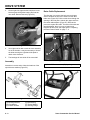
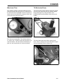
10. On the left side of the engine, is an engine brace
which is bolted to the side plate in 3 places (Figure
24). Remove all three bolts.
Figure 25
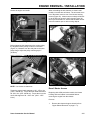
12. Tip the machine forward and remove the 3
locknuts securing the center pivot bracket (Figure
26). They are on studs, so it will not be necessary
to try to hold the bolt head.
Figure 26
Figure 24
3428-0237
3428-0251
3428-0246
11. Remove the engine pulley. Loosen 2 set screws
and pull the pulley straight off (Figure 25).
Snow Commander Service Manual
3-3
ENGINE REMOVAL / INSTALLATION
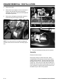
13. Remove 2 bolts right in front of the engine. It will
be necessary to reach under the unit to access the
locknuts (Figure 27).
Assembly
Reverse the order.
If the engine was removed from the cradle, torque the 4
bolts around the crankshaft to 170 - 220 in. lbs (1355 2483 N·cm).
B
A
However, leave the bolts securing the engine cradle
slightly loose until the engine location can be checked
and adjusted.
Adjust the engine to achieve the same gap between
the idler pulley and engine pulley, as measured
previously (Figure 29). Then snug the mounting
screws to hold the engine in place.
Figure 27
(A) Engine
3428-0242
(B) Starter Motor
14. The engine and engine cradle will now lift out of
the chassis.
15. Remove the 3 locknuts shown in Figure 28 to
access the recoil starter. Also the engine cradle
and engine can be separated if necessary.
Figure 29
3428-0232
To assure the engine is properly located in the housing,
measure the distance between the carburetor and the
left side of the opening. When the engine is correct, the
gap should be .030” (.762mm) (Figure 30). NOTE: If
this check is not done, the choke lever may hang up on
the shroud.
Figure 28
3-4
3428-0247
Snow Commander Service Manual
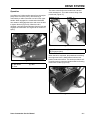
ENGINE REMOVAL / INSTALLATION
When reinstalling the wire harness on electric start
models, route the wire as follows: The wire must come
out of the starter motor to one of the blower housing
screws (Figure 32). It then must run under the fuel tank
up to the left rear mount for the fuel tank (Figure 33),
then up to the switch box. Assure that the wires will not
rub on the starter rope or other moving objects.
Secure the engine and cradle.
Figure 30
3428-0211
Before tightening the setscrews on the engine pulley,
the alignment of the pulleys needs to be checked
(Figure 31). Measure from the side plate to the outer
pulley flange. Adjust the pulley until the gap is 1”
(25.4mm).
Figure 31
Figure 32
mvc-496
Figure 33
mvc-497
mvc-504
NOTE: Use Loctite on setscrews.
Torque the square head setscrew to 120 - 150 in. lbs.
(1355 - 1694 N·cm). Torque the Allen head setscrew to
60 - 80 in. lbs. (678 - 904 N·cm). Torque the nut on the
recoil side support to 90 - 120 in. lbs. (1016 - 1355
N·cm).
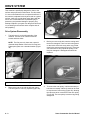
Recoil Starter Access
Beginning with 2002 production models, the blower
housing and recoil starter is accessible without
removing the engine from the chassis:
Process:
1.
Snow Commander Service Manual
Remove the chute and upper shroud (refer to
“Upper Shroud Removal” on page 2 - 3).
3-5
ENGINE REMOVAL / INSTALLATION
2.
Remove fuel tank.
3.
Remove the recoil support. You can remove the 2
bottom nuts and bolts and leave the support
attached to the recoil or remove all 3 and separate
the support (Figure 28).
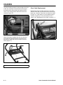
4.
Remove the self-tapping screws that secure the
blower housing to the engine (Figure 34).
Figure 34
3428-0249
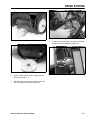
NOTE: One screw must be accessed by tipping the
machine. Drain fuel from the tank if necessary (Figure
35).
Figure 35
5.
The recoil and blower housing can be removed.
Assembly
Reverse the above steps.
Note wiring routing on electric start units. When
reinstalling the wire harness on electric start models,
route the wire as follows: The wire must come out of
the starter motor to one of the blower housing screws
(Figure 32). It then must run under the fuel tank up to
the left rear mount for the fuel tank (Figure 33), then up
to the switch box. Assure that the wires will not rub on
the starter rope or other moving objects.
3-6
Snow Commander Service Manual
DRIVE SYSTEM
Operation
A multigrooved V belt transfers power from the engine
pulley to the rotor drive pulley. Belt clutching is
controlled by a cable connected to a bail on the upper
handle. When engaged, the combination idler/brake
arm rotates to disengage the brake and move the idler
to tighten the belt (Figure 36). When the bail is
released, a spring pulls the idler away from the belt and
engages the rotor brake. See Figure 46 for location of
spring.
B
A
C
C
A
The same control bail on the handle has a second
cable attached to it. This cable controls tilting of the
powerhead (Figure 37).
C
B
Figure 37
(A) At Rest
(B) Engaged (tilted)
Figure 36
(A) Belt Brake
(B) Pivot
(C) Idler
0621-0083
(C) Cable
When the bail is squeezed, the powerhead containing
the engine and rotor is tilted forward until the rotor
blades contact the surface. This action provides a selfpropelling action by the rotor blades as well as cleaning
down to the surface (Figure 38).
Figure 38
Snow Commander Service Manual
3428-0206/3428-0207
3428-0229
4-1
DRIVE SYSTEM
This machine is specifically designed to clean to the
surface and propel itself in this manner. For this reason
it is not recommended for use on unpaved surfaces. If
the machine is adjusted correctly and used on a gravel
surface, it will pick up and throw gravel along with the
snow. This is undesirable due to possible injury to
passers by and potential damage to property. Any
attempt to adjust it up to pass over the gravel will result
in not cleaning to the surface and a complete loss of
self-propelling.
Drive System Disassembly
1.
The belt cover is on the left-hand side of the
machine. The belt cover is held on with two
screws and three bolts.
NOTE: The first year only there was a special
diamond shape washer used in the front top hole.
Subsequent years use a standard washer (Figure
39).
Figure 40
3.
0621-0083
Before you remove the belt, note the routing and if
the belt is damaged. There is a belt routing decal
on the inside of the belt cover and a copy of that
decal in the owners manual (Figure 41). If the belt
was misrouted or has jumped the pulleys, it will
likely be damaged. A damaged belt should be
replaced.
X
A
B
Figure 39
(A) Diamond Shaped Washer
2.
4-2
3428-0230
(B) Belt Cover
Remove the belt cover and the left rotor guard.
The belt system is now fully exposed (Figure 40).
Figure 41
4.
3428-0231-2
To remove the rotor pulley, it will be necessary to
hold the rotor steady. A block of wood can be used
to stop the rotor from turning (Figure 42), allowing
the capscrew to be removed from the rotor pulley
(Figure 43). The rotor pulley is removed by pulling
straight off.
Snow Commander Service Manual
DRIVE SYSTEM
Figure 42
Figure 44
7.
Figure 43
To remove the engine pulley, loosen the setscrews
and pull the pulley straight off (Figure 45).
3428-0272
5.
Remove upper shroud, refer to “Upper Shroud
Removal” on page 2 - 3.
6.
The idler pulley is secured to the idler/brake arm
with a capscrew and locknut (Figure 44).
Snow Commander Service Manual
3428-0244
3428-0250
Figure 45
3428-0237
4-3
DRIVE SYSTEM
8.
To remove the brake arm, first unhook the brake
spring (Figure 46). The brake arm is attached by a
single shoulder bolt through the side plate (Figure
47). Remove the locknut and large washer. Pull
the brake arm off carefully as there is a pivot
washer between the brake arm and side plate.
A
Figure 48
3428-0236
(A) Cap Nut
Drive System Assembly
Figure 46
3428-0240
Assemble in reverse order. The following are tips to
assist you.
1.
Figure 47
9.
4-4
Many of the capscrews and nuts are the locking
type. However, the material in the threads that
provides the locking feature, wears out. If the parts
assemble easily, we suggest either replacing the
locknut or capscrew or, cleaning the screw
threads and applying a chemical thread locker
such as Loctite brand.
3428-0243
Replace nylon rollers if worn or damaged. One is
retained by a cap nut (Figure 48). Use side
cutters to remove it, and replace with a new cap
nut.
Snow Commander Service Manual
DRIVE SYSTEM
2.
Before tightening the setscrews on the engine
pulley, the alignment of the pulleys needs to be
checked (Figure 49). Measure from the side plate
to the outer pulley flange. Adjust the pulley until
the gap is 1” (25.4mm).
4.
Check the belt adjustment even if the belt was not
replaced. Most belt failures are due to not
maintaining proper adjustment. Refer to "Rotor
Control Cable" on page 5 - 1.
Rotor Bearing Replacement
Figure 49
1.
To replace the rotor bearings, remove the belt
cover, belt and rotor pulley as shown in the
preceding steps.
2.
Remove the three nuts and bolts attaching the
bearing and bearing retainers to each side plate
(Figure 51).
mvc-504
Torque the square head setscrew to 120 - 150 in.
lbs. (1355 - 1694 N·cm). Torque the Allen head
setscrew to 60 - 80 in. lbs. (678 - 904 N·cm).
Torque the capscrew securing the rotor pulley to
100 in. lbs. (1125 N·cm).
3.
The idler pulley must be installed with the longer
hub towards the brake arm (Figure 50). If it is
installed backwards, it will not rotate when
tightened down. Torque the shoulder bolt to 170 250 in. lbs. (1920 - 2824 N·cm).
Figure 51
3428-0273
A
Figure 50
3428-0245
(A) Hub
Snow Commander Service Manual
4-5
DRIVE SYSTEM
3.
On the right side (opposite the belt) there is one
bolt that goes through the bearing and into the
rotor shaft. Remove this bolt (Figure 52).
Rotor Cable Replacement
The first step is to remove the belt cover and upper
shroud. Unhook the end of the cable from the idler/
brake arm (Figure 54). Pull the cable down through the
opening in the side plate. Unhook the upper end from
the clutch cable adjuster (Figure 55). Reverse the
process to replace the cable. The ends of the cable are
interchangeable; there is no top or bottom end.
Replace the belt cover and adjust per the "Adjusting
the Rotor Control Cable" on page 7 - 2.
A
Figure 52
4.
5.
3428-0275
You might now be able to work the rotor assembly
out of the chassis. It may be necessary to loosen
the bolts securing the right-hand side plate to
obtain more clearance.
B
The bearings will now slide off the rotor shaft.
Figure 54
Assembly
Assemble in reverse order. Note the locations of the
special thrust washers (Figure 53).
Figure 53
(A) Bearing Retainer
(B) Flat Washer
(C) Rubber Washer
4-6
(A) Cable Z Bend
mvc-502
(B) Opening
Figure 55
3428-0198
(D) Ball Bearing
(E) Thrust Washer
(F) Bearing Flange
Snow Commander Service Manual
ELECTRIC START SYSTEM
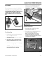
Operation
If there is no continuity with the starter button
depressed, the switch box will need to be
removed and opened. Proceed to Disassembly.
The electric start system consists of a 120 (USA) or
220 (Europe) VAC motor, a momentary switch, a plug
terminal, and a connecting wire (Figure 56). A cord
from a household power supply is plugged into the
machine. When the starter button is depressed, current
is directed to the motor. When the engine starts,
release the starter button and unplug the extension
cord.
A
Figure 57
3428-0259
(A) Starter Button
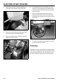
System Disassembly
Figure 56
1.
Remove the upper shroud. Refer to “Upper
Shroud Removal” on page 2 - 3.
2.
Remove three screws holding the switch box to
the control panel support (Figure 58).
3428-0257
Troubleshooting
1.
First check the electric outlet. An easy way to do
that is plug a light into that outlet.
2.
Substitute a different extension cord or plug the
same light into the cord.
3.
If the cord and outlet are supplying power, the
problem must be in the motor, wires, or switch.
4.
A continuity tester or ohmmeter can be connected
to the terminals where you would normally plug in
the extension cord (Figure 57).
NOTE: At this point, the switch box can be
opened and the parts tested. It may not be
necessary to remove the starter motor. Proceed to
"Switch Box Repair" on page 5 - 3
NOTE: For clarity, the switch box has been
removed and opened. Normally, this test would be
done with the machine fully assembled.
Figure 58
Snow Commander Service Manual
3428-0228
5-1
ELECTRIC START SYSTEM
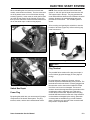
3.
Remove the left rear fuel tank mounting bolt
securing the wire harness clamp (Figure 59).
Figure 59
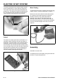
6.
To access the other motor mounting screw, the
machine must be tipped forward. Depending on
how much fuel is in the tank it may be necessary
to drain the tank.
7.
Tip the machine forward and reach in with a
ratchet and extension to remove the last motor
mounting screw through the access hole provided
(Figure 61).
3428-0223
4.
Remove one screw (A) (Figure 60) which holds
the wire harness to the blower housing.
5.
Remove one starter motor mounting screw (B)
(Figure 60) from the front.
Figure 61
8.
3428-0253
The motor, wire harness and switch box can now
be removed from the chassis.
Assembly
A
Assemble in reverse order. When mounting the starter
motor itself, we suggest that you loosely install the front
or top mounting screw first. This will make it easier to
line up the motor and start the rear mounting screw.
B
Figure 60
5-2
3428-0249
Snow Commander Service Manual
ELECTRIC START SYSTEM
When reinstalling the wire harness on electric start
models, route the wire as follows: The wire must come
out of the starter motor to one of the blower housing
screws (Figure 62). It then must run under the fuel tank
up to the left rear mount for the fuel tank (Figure 63)
then up to the switch box. Assure that the wires will not
rub on the starter rope or other moving objects.
NOTE: There are two versions of the electric start
system. A 120 VAC sold in North America and a 220
VAC system sold in Europe. The plug terminal and
motor will be different because of the different electrical
systems. However, the troubleshooting and repair
procedures are the same. The 120VAC system is
shown.
After removing and opening the switch box, note the
location of all wires (Figure 64) before removing any
parts from the box.
X
Figure 62
mvc-496
X
Figure 64
X
3428-0258 / -0260
To Motor
Plug Terminal
The possible failure modes of the plug are simple. It
can be broken (physical damage) or burnt (signs of
arcing).
Figure 63
mvc-497
Switch Box Repair
Power Plug
By opening the switch box you can access all (3) major
components of the electric start system. The plug
terminal, switch, and the wire harness/starter motor.
Snow Commander Service Manual
Physical damage is apparent. However, a burnt
terminal requires an understanding of the process. The
terminal becomes burnt when it is loosely plugged into
the extension cord or the terminal inside the female
end of the cord is worn or damaged. The loose fit
results in electrical arcing between the terminals on the
snowthrower and the extension cord. This arcing
causes the burnt terminals. Replace BOTH the plug
terminal AND the terminal on the end of the extension
cord as both are damaged by the arcing. (Extension
cord terminals are available at your local hardware
store.) Replacing only one half of the connection will
likely result in a repeat failure.
5-3
ELECTRIC START SYSTEM
To remove the wires from the switch, slip the smooth
end of a small drill bit in next to the wire (Figure 65).
The inside of the switch has spring loaded jaws that
grip the wire. The jaws will not grab the hardened drill
bit. This allows the drill to be easily removed after it
opens the jaws to allow the wire to be removed.
Figure 65
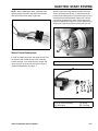
Motor Testing
To properly test the motor it must be removed from the
chassis. Refer to "System Disassembly" on page 5 - 1.
Remove the two motor wires from the switch (Figure
67). Attach one ohmmeter test lead to each wire.
SLOWLY rotate the motor shaft and watch the
ohmmeter. At no time should continuity be lost,
although it will fluctuate. The motor comes with the
wires permanently attached. If the wires are damaged
or there is internal damage to the motor, it must be
replaced.
3428-0262
Switch
The switch is a simple push button on/off switch. It is
intended to make continuity only when the button is
depressed. To test the switch, use a continuity light or
ohmmeter. Remove the wires and insert the probes
from the tester. Use two holes that are directly across
from each other (Figure 66). With the button depressed
there should be continuity, when it is released there
should be no continuity. At no time should there be
continuity between the diagonal terminals.
Figure 67
0621-0086
Assembly
Assemble in reverse order.
To install the wires in the switch merely push them into
the holes. The jaws will grab them.
Figure 66
5-4
3428-0270
Snow Commander Service Manual
ELECTRIC START SYSTEM
NOTE: When installing the wires, install the black
wires directly across from each other and the light
wires across from each other (Figure 68).
Figure 68
3428-0261
Starter Pinion Replacement
In order to replace the pinion, the upper shroud must
be removed and at least the two motor mounting
screws removed. If you know the wire, switch, and
motor are all ok, they can be left in place. Refer to
"System Disassembly" on page 5 - 1.
With the motor mounting screws removed, the motor
can be accessed from the top. To remove the pinion,
push the pinion stop down to uncover the wire lock ring
around the end of the armature (Figure 69). The lock
ring can be grasped with a pliers or side cutters and
pulled off. Replace the ring; do not re-use. With the ring
off the pinion and spring can be removed (Figure 70).
A
B
Figure 69
(A) Ring
(B) Pinion Stop
A
Figure 70
(A) & (B) Pinion Assembly
(C) Pinion Stop
Snow Commander Service Manual
3428-0264
B C DE
3428-0266
(D) Spring
(E) Lock Ring
5-5
ELECTRIC START SYSTEM
Assembly
Apply a thin coat of light weight oil to the motor shaft.
Just enough to prevent rust.
Slip the pinion and spring on the shaft. Slide the pinion
stop on with the recessed side facing outward. Press
the lock ring on over the end of the motor shaft.
Sometimes a small socket helps when used like a seal
installer (Figure 71).
Figure 71
3428-0269
The pinion stop should come outward and keep the
lock ring from coming out of the groove (Figure 72).
Figure 72
3428-0265
Slip the starter motor back into place. Loosely install
the front/top mounting screw. then tip the machine
forward to install the bottom screw. Tighten both
mounting screws.
5-6
Snow Commander Service Manual
CHASSIS
Wheels and Tires
Tilt Mechanism/Frame
The machine is setting on two solid rubber front tires
and two pneumatic rear tires (Figure 73). Should one of
the front tires become damaged, remove one push nut
and the axle can be pulled out to replace a wheel. Use
a new push nut to secure the wheel.
The basic function of this machine requires the engine
and rotor to tilt forward until the rotor blades engage
the ground (Figure 74). This provides the selfpropelling action and the ability to clean down to the
surface.
Figure 73
Figure 74
3428-0203
The rear tires are pneumatic. The normal pressure is
15 - 20 psi. (103 - 137kPa). In this case, pressure is not
critical to function. The rear wheels are retained by a
push nut. Use a new push nut to secure the wheel.
The wheel frame stays level with the ground at all
times. There is a hinge point at the front that the engine
and rotor assembly pivots on (Figure 75).
Figure 75
Snow Commander Service Manual
3428-0207-2
3428-0208
6-1
CHASSIS
The normal resting position is with the engine and rotor
to the rear. A spring connected between the engine
and wheel frame assures that the engine and rotor
return to the resting position when the controls are
released (Figure 76).
Figure 76
Pivot Cable Replacement
Replacement of the tilt cable requires no tools. Both
ends are made with a Z bend and can be removed by
hand only. Insert the Z bend into the handle as shown
in Figure 78. If the cable is not connected this way, it
will have a tendency to come unhooked from the
handle. See "Adjusting the Pivot Cable" on page 7 - 3.
3428-0211
When the operator engages the bail, the cable that
runs down the right-hand handle causes the pivot
assembly to rotate and move the engine and rotor
frame (Figure 77).
Figure 78
mvc-492
A
Figure 77
3428-0199
(A) Pivot Cable
6-2
Snow Commander Service Manual
MAINTENANCE
NOTE: Determine the left and right side of the machine from the normal operating position.
Recommended Maintenance Schedule
Maintenance Service
Interval
Maintenance Procedure
•
Check the rotor control cable and the pivot cable initially, and after the first hour of
operation. Adjust if necessary.
•
Check for loose fasteners and tighten if necessary.
•
Check the rotor control cable and the pivot cable. Adjust if necessary.
•
Inspect the rotor blades and replace if necessary. Replace the scraper when you
replace the rotor blades.
•
Inspect the scraper and replace if necessary. If the rotor blades are partially or
completely worn, replace the rotor blades when you replace the scraper.
•
Inspect and gap the spark plug; replace if necessary.
•
Inspect the drive belt and replace if necessary.
•
For storage, add stabilizer, drain the fuel, and run the engine until the fuel tank and
the carburetor are empty.
•
Check the pressure in the tires and inflate them to between 15 and 20 psi (103 and
137 kPa).
•
Check for loose fasteners and tighten them if necessary.
Initial
Annually
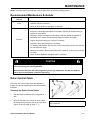
CAUTION
If you leave the wire on the spark plug, someone could start the engine accidentally and
seriously injure you or other bystanders.
Disconnect the wire from the spark plug before you do any maintenance. Set the wire aside so
that it does not accidentally contact the spark plug.
Rotor Control Cable
Check the rotor control cable for proper adjustment
initially, after the first operating hour, and then annually
thereafter.
Checking the Rotor Control Cable
1.
Stop the engine and wait for all moving parts to
stop.
2.
Move the left side of the control bar back toward
the handle until you remove the slack in the cable
(Figure 79 and "m-5065" on page 7 - 1).
Figure 79
Snow Commander Service Manual
(A) Rotor Control Cable
(B) Control Bar
m-5065
(C) Handle
7-1
MAINTENANCE
3.
Ensure that a 1/8 to 1/4 inch (3 to 6mm) gap exists
between the control bar bracket and the handle as
shown in Figure 80.
Figure 80
(A) Control Bar Bracket
(B) 1/8 to 1/4 in. (3 to 6mm) gap
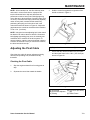
Adjusting the Rotor Control Cable
1.
Unhook the spring end from the hole in the center
of the control bar bracket (G) as shown in Figure
81.
m-5069
Figure 81
(C) Handle
Important The rotor control cable must have slack
in it when you disengage the control bar in order for the
rotor brake to operate properly.
(A)
(B)
(C)
(D)
Cable
Z-fitting
Cable Adjuster
Spring
m-5054
(E) Spring Cover
(F) Control Bar Bracket
(G) Hole in the center of
the control bar bracket
2.
Slide the spring cover off the cable adjuster.
3.
Unhook the Z-fitting from the cable adjuster
(Figure 81), and position it in a different hole on
the adjuster to obtain specified gap of 1/8 to 1/4
inch (3 to 6mm) between the control bar bracket
and the handle (Figure 80).
NOTE: Moving the Z-fitting to a hole closer to the
spring decreases the gap between the control bar
bracket and the handle; moving it to a hole farther from
the spring increases the gap.
7-2
4.
Install the spring cover over the cable adjuster.
5.
Hook the spring into the hole in the center of the
control bar bracket as shown in Figure 81.
6.
Check the adjustment ("Checking the Rotor
Control Cable" on page 7 - 1).
Snow Commander Service Manual
MAINTENANCE
NOTE: After extended use, the drive belt may wear
and result in a loss of belt tension. Improper belt
tension allows the belt to slip and decreases the
performance under a heavy load. Belt slippage may
occur after two or three seasons of normal usage (10 to
15 hours). If the drive belt slips (continuously squeals)
under a heavy load, increase the belt tension by
positioning the spring end in the other hole in the
control bar bracket as shown in Figure 81. Adjust the
gap between the control bar bracket and the handle to
1/8 to 1/4 in. (3 to 6mm).
3.
NOTE: Using the incorrect adjusting hole in the control
bar bracket can reduce the drive belt life. Occasional
belt slippage (squealing) may occur in extremely wet
conditions due to moisture in the drive system. To
remove moisture, start the rotor and operate it without
a load for 30 seconds. Once you remove the moisture,
the drive belt should not slip.
Adjusting the Pivot Cable
Figure 82
(A) Right side of the control bar
4.
Check the pivot cable for proper adjustment initially,
after the first operating hour, and then annually
thereafter.
Hold the control bar against the right side of the
handle as shown in Figure 11.
m-5066
(B) Handle
Ensure that the distance between the pivot plate
and the wheel frame is 0 to 1/8 in. (0 to 3mm) as
shown in Figure 83.
Checking the Pivot Cable
1.
Stop the engine and wait for all moving parts to
stop.
2.
Squeeze the control bar toward the handle.
Figure 83
(A) Pivot Plate
(B) Pivot Cable Adjuster
(C) Z-fitting
Snow Commander Service Manual
m-5056
(D) 0 to 1/8 in. (0 to 3mm)
gap
(E) Wheel Frame
7-3
MAINTENANCE
Important If the pivot plate touches the wheel
frame before the control bar touches the handle, the
cable is too tight. Adjust the cable to increase the gap
between the pivot plate and the wheel frame, but
ensure that the gap is not more than 1/8 in. (3mm).
Adjusting the cable correctly minimizes the effort
needed to operate the control bar.
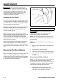
Adjusting the Pivot Cable
Unhook the Z-fitting from the pivot cable adjuster (Fig.
12), and position the Z-fitting in a different hole on the
pivot cable adjuster to obtain the proper gap between
the pivot plate and the wheel frame.
Note: Moving the Z-fitting to a hole closer to the ground
decreases the gap between the pivot plate and the
wheel frame; moving it to a hole farther from the
ground increases the gap.
Note: The traction is most aggressive (the traction
speed is fastest) when the rotor blades are new. If you
want to reduce the aggressiveness of the traction,
move the Z-fitting one hole farther from the ground.
The gap between the pivot plate and the wheel frame
will be about 1/4 in. (6mm).
Figure 84
m-5058
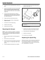
(A) Rotor blade wear indicator hole
Important Replace the scraper whenever you
replace the rotor blades. This ensures proper
snowthrower operation and performance.
NOTE: The running time and the roughness of the
driveway or the sidewalk determines the wear rate of
the rotor blades.
After the rotor blades have worn slightly, the traction
won’t feel as aggressive. To increase the traction,
adjust the pivot cable to attain the original gap between
the pivot plate and the wheel frame of 0 to 1/8 in. (0 to
3mm).
NOTE: You need a T27 Torx driver to complete this
procedure.
1.
Stop the engine and wait for all moving parts to
stop.
Replacing the Rotor Blades
2.
Remove the key from the switch.
3.
Disconnect the wire from the spark plug. Refer to
steps 1 through 3 of "Replacing the Spark Plug"
on page 7 - 6.
Before each season, inspect the rotor blades for wear.
When a rotor blade edge has worn to the wear
indicator hole (Figure 84), replace all three rotor blades
to ensure proper performance and to prevent damage
to the underside of the snowthrower.
Removing the Old Rotor Blades
NOTE: To make replacing the rotor blades easier, do
not remove all the old rotor blades at once; this
disassembles the rotor drum, making installing the new
rotor blades more difficult. Replace the rotor blades
one at a time to keep the rotor drum intact.
1.
7-4
Remove the four Torx screws and the four
locknuts that secure the outer edges of the rotor
blade to the rotor assembly (Figure 85).
Snow Commander Service Manual
MAINTENANCE
Figure 85
(A) Thick rubber side of the
rotor blade (3)
(B) Rotor Assembly
(C) Rotor Drum
2.
Remove the two hex-head cap screws and two
locknuts that secure the center of the rotor blade
to the rotor drum (Figure 85).
3.
Slide the rotor blade out from between the rotor
drum parts (Figure 85).
4.
Remove the two spacers from the old rotor blade
and install them in the new blade.
m-5057
(D) Locknut (18)
(E) Torx Screw (12)
(F) Spacer (6)
(G) Hex-head Cap Screw (6)
Installing the New Rotor Blades
1.
Examine a new rotor blade edge for the difference
in the thickness of the rubber layers (Figure 86).
Figure 86
(A) Thick Rubber Side
(B) Wear Indicator Hole
m-5059
(C) Thin Rubber Side
Install the rotor blades with the thick rubber layer
on the inside of the curve. (Figure 86). If you do
not install the rotor blades properly, they will wear
more quickly and may vibrate excessively.
Snow Commander Service Manual
7-5
MAINTENANCE
2.
Insert the new rotor blade between the rotor drum
parts.
3.
Secure the rotor blade to the rotor drum parts with
the two hex-head cap screws and two locknuts
that you previously removed. Position the bolt
heads on the thick rubber side of the rotor blade
(Figure 85).
4.
Curve the rotor blade and secure it with the
remaining Torx screws and locknuts, positioning
the screw heads on the thick rubber side of the
rotor blade (Figure 85).
5.
Tighten all screws and locknuts securely.
6.
Replace the scraper. Refer to “Replacing the
Scraper” (below).
7.
Connect the wire to the spark plug.
8.
Install the control panel.
9.
Insert the key in the switch.
5.
Remove the six bolts and locknuts that hold the
scraper in place (Fig. 17).
Figure 87
(A) Carriage Bolt (6)
(B) Locknut (6)
m-5060
(C) Scrapper
6.
Remove the scraper.
Replacing the Scraper
7.
Install the new scraper to the housing using the
bolts and the locknuts you previously removed.
NOTE: If the rotor blades are partially or completely
worn, replace the rotor blades when you replace the
scraper. This ensures proper snowthrower operation
and performance.
8.
Connect the wire to the spark plug.
9.
Install the control panel.
1.
Stop the engine and wait for all moving parts to
stop.
2.
Remove the key from the switch.
3.
Disconnect the wire from the spark plug. Refer to
steps 1 through 3 of “Replacing the Spark Plug”
(below).
4.
Tip the snowthrower backward onto its handle.
7-6
10. Insert the key in the switch.
Replacing the Spark Plug
Before each season, check the spark plug. Replace the
plug if fouled with deposits or if the electrodes in the
center of the plug are dark or have deteriorated spark
plug - NGK BPMR4A or equivalent.
Snow Commander Service Manual
MAINTENANCE
1.
Remove the two mounting screws that secure the
control panel to the housing (Fig. 18).
6.
Examine the spark plug and replace it if it is
cracked, fouled, or dirty.
Important Do not sandblast, scrape, or clean the
spark plug. Dirt may fall into the cylinder and cause
engine damage.
7.
Figure 88
(A) Control Panel
Set the spark plug gap (Figure 90) between the
electrodes to 0.030 in. (0.76mm).
m-5061
Figure 90
(B) Mounting Screws (2)
2.
Remove the ignition key and lift off the panel,
allowing it to hang on the recoil rope.
3.
Lift up the shroud and disconnect the wire from
the spark plug (Figure 89).
m-3215
8.
Install the spark plug and torque it to 15 ft-lb
(20.4 N·m). If you do not have a torque wrench,
tighten the plug firmly.
9.
Connect the wire to the spark plug.
10. Install the control panel.
Replacing the Drive Belt
Inspect the drive belt before each season, and replace
it if it is worn or damaged.
Figure 89
(A) Shroud
m-5062
1.
Stop the engine and wait for all moving parts to
stop.
2.
Remove the key from the switch.
3.
Disconnect the wire from the spark plug. Refer to
steps 1 through 3 of "Replacing the Spark Plug"
on page 7 - 6.
(B) Spark Plug Wire
4.
Clean any debris from around the base of the
spark plug.
5.
Remove the spark plug (Figure 89).
Snow Commander Service Manual
7-7
MAINTENANCE
4.
Remove the two self-tapping screws, three cap
screws, one washer, and three locknuts that
secure the drive belt cover to the snowthrower
frame (Figure 91). Set the drive belt cover aside.
6.
Remove the old drive belt from the engine pulley
and the idler pulley (Figure 92).
Figure 92
Figure 91
(A) Drive Belt Cover
(B) Left Rotor Guard
(C) Washer (diamondshaped on some
models)
m-5064
(D) Snowthrower Frame
(E) Self-Tapping Screws
(A)
(B)
(C)
(D)
Brake Arm Assembly
Idler Pulley
Roller
Engine Pulley
m-5063
(E) Belt Guides
(F) Rotor Pulley
(G) Left Rotor Guard
7.
Push down on the idler pulley and remove the
drive belt from the rotor pulley (Figure 92).
Remove the left rotor guard (Figure 91) and save
it for installation in step 10.
8.
Push down on the idler pulley and route the new
drive belt around the rotor pulley (Figure 92).
Important The left rotor guard acts as a water seal
for the drive. Do not assemble the drive cover without
installing this part or the drive belt will slip and fail.
9.
Release the idler pulley and route the drive belt
over the two belt guides, around the engine pulley,
and between the idler pulley and the roller (Figure
92).
5.
Important The drive belt must be on top of the roller
and the two belt guides as shown in Figure 92.
10. Install the left rotor guard.
11. Install the drive belt cover. Tighten the fasteners
securely, but do not overtighten.
NOTE: Install the diamond-shaped washer as shown
in Figure 91 and Figure 93.
7-8
Snow Commander Service Manual
MAINTENANCE
12. Connect the wire to the spark plug.
13. Install the control panel.
14. Insert the key in the switch.
Checking the Tire Pressure
Figure 93
m-5076
(A) Locknut
(C) Housing
(B) Washer (diamond-shaped on some
models)
Inflate both tires to between 15 and 20 psi (103 and
137 kPA).
Troubleshooting
Problem
Possible Causes
Electric starter does not 1. The power cord is disconnected at the
turn (electric-start
outlet or the snowthrower.
models only)
2. The power cord is worn, corroded, or
damaged.
3. The power outlet is not energized.
Corrective Action
1. Connect the power cord to the outlet
and/or the snowthrower.
2. Replace the power cord.
3. Have a qualified electrician energize the
power outlet.
Engine does not start or 1. The key is not in the ignition or is in the 1. Insert the key into the ignition and turn it
starts hard
Off position.
to the On position.
2. The choke is in the Off position and the 2. Move the choke to the On position and
primer has not been pressed.
press the primer two times.
Engine runs rough
3. The fuel tank is empty or the fuel
system contains stale fuel.
3. Drain and fill the fuel tank with a fresh
gasoline-and-oil mixture (not more than
30 days old). If the problem persists,
contact an Authorized Service Dealer.
4. The engine is flooded.
4. Move the choke to the Off position and
pull the rope several times to clear out
the rich fuel-and-air mixture from the
engine.
5. The spark plug wire is loose or
disconnected.
5. Connect the wire to the spark plug.
6. The spark plug is pitted, fouled, or the
gap is incorrect.
6. Check the spark plug and adjust the gap
if necessary. Replace the spark plug if it
is pitted, fouled, or cracked.
7. The fuel cap vent is restricted.
7. Remove the vent restriction or replace
the fuel cap.
1. The choke is in the On position.
1. Move the choke to the Off position.
2. The fuel system contains stale fuel.
2. Drain and fill the fuel tank with a fresh
gasoline-and-oil mixture (not more than
30 days old). If the problem persists,
contact an Authorized Service Dealer.
3. The spark-plug wire is loose.
3. Connect the wire to the spark plug.
4. The spark plug is pitted, fouled, or the
gap is incorrect.
4. Check the spark plug and adjust the gap
if necessary. Replace the spark plug if it
is pitted, fouled, or cracked.
Snow Commander Service Manual
7-9
MAINTENANCE
Troubleshooting
Problem
Possible Causes
Engine runs, but the
1. You are walking too fast or too slow.
snowthrower discharges 2. You are trying to remove too much
snow poorly or not at all
snow per swath.
Snowthrower does not
properly clear snow off
the surface
Corrective Action
1. Change your walking speed.
2. Reduce the amount of snow removed
per swath.
3. You are trying to remove extremely
heavy or wet snow.
3. Don’t overload the snowthrower with
extremely heavy or wet snow; reduce
the amount of snow removed per swath.
4. The discharge chute is plugged.
4. Stop the engine, wait for all moving
parts to stop, and use a stick to remove
the snow from the discharge chute.
5. The rotor control cable is improperly
adjusted or broken.
5. Adjust or replace the rotor control cable.
6. The drive belt is loose or is off the
pulley.
6. Inspect the drive belt, and install or
replace it.
7. The drive belt is worn or broken.
7. Replace the drive belt.
8. The rotor blades are worn.
8. Replace the rotor blades and the
scraper.
1. The snow on the surface to be cleared
is compacted down
1.
2. The front of the snowthrower is not
down.
2. Check the pivot cable, and adjust or
replace it.
3. The scraper is excessively worn.
3. Replace the scraper and the rotor
blades.
Throw the snow off the surface before
it becomes compacted.
4. The rotor blades are excessively worn. 4. Replace the rotor blades and the
scraper.
Snowthrower does not
self-propel
1. The front of the snowthrower is not
down.
1. Check the pivot cable, and adjust or
replace it.
2. The rotor blades are excessively worn. 2. Replace the rotor blades and the
scraper.
Rotor blades do not
stop properly
7 - 10
3. The snow is too deep or the surface is
too slippery.
3. Push forward on the handle, but allow
the snowthrower to work at its own
pace.
1. The rotor control cable is improperly
adjusted.
1. Adjust the rotor control cable.
Snow Commander Service Manual
MAINTENANCE
SPECIFICATIONS (General)
Item
Description
Engine Mfg.
The Toro Company 141cc E series (R tek)
Fuel Mix Ratio
50:1
Spark Plug
NGK
BPMR4A or equivalent
Fuel Capacity
1.2 US quart (1.1 l)
Weight
113 lbs. (51.4 kg) (recoil start)
115 lbs. (52.3 kg) (electric start)
Width
24.3” (61.7 cm)
Height
40.4” (102.6 cm) (highest point)
Length
51.3” (130.3 cm)
Chute Rotation
210 degrees
Chute Throat Diameter
6.2” (15.7 cm)
Impeller Diameter
10” (25.4 cm)
Rotor Drive Reduction
3.95:1
TORQUE SPECIFICATIONS
Torque Value
Description / Where Used
In-Lbs
N·cm
Engine Pulley
Square Head Set Screw
Allen Head Set Screw
120 - 150
60 - 80
1355 - 1694
678 - 904
Nut On Recoil Support
90 - 120
1016 - 1355
Engine Mounting Screws
170 - 220
1920 - 2483
100
1125
170 - 250
1920 - 2824
(Must pivot freely)
Rotor Pulley Capscrew
Brake Arm Shoulder Bolt
Plastite Screws
Tighten securely, but do not deform the plastic
Belt Cover Top Screw (has an O-ring on it)
Tighten to compress O-ring to .08” - .11” (2.03 - 2.79mm) thick.
LUBRICATION
Engine - “Fuel and Oil Requirements” on page 1 - 6.
Engine crankshaft pulley. Apply anti-seize compound to shaft before installation of pulley.
Apply a light coat of #2 general purpose grease to the brake arm, shoulder bolt, and washers.
Snow Commander Service Manual
7 - 11
THIS PAGE INTENTIONALLY LEFT BLANK
7 - 12
Snow Commander Service Manual
492-4739