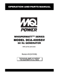
1
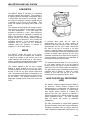
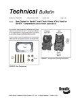
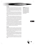
Service
Manual
Liquefied Petroleum Gas (LPG)
Fuel System
for
1994-1998 GM Medium Duty Chassis
(C-60/C-70)
with
6.0L and 7.0L V8
CONTENTS
Vehicle Application ........................................................................................................................1
Propane Fuel System Warning .....................................................................................................1
General Description .......................................................................................................................1
Propane Fuel System ........................................................................................................1
Converter............................................................................................................................2
Mixer ...................................................................................................................................2
Adaptive Digital Processor (ADP)....................................................................................2
IMPCO® Programmable Read-Only Memory (PROM) ....................................................3
Electric Lock-off Solenoid ................................................................................................3
Fuel and Idle Control Valves ............................................................................................3
Regulator Control Valve (RCV) ........................................................................................4
Diagnosis ........................................................................................................................................5
Electrical Schematic .........................................................................................................5
Symptom Diagnosis ..........................................................................................................6
Important Preliminary Checks ............................................................................6
Hard Start ..............................................................................................................7
Surges/Chuggles ..................................................................................................9
Lack of Power, Sluggishness, or Sponginess ................................................10
Hesitation, Sag, Stumble ...................................................................................11
Cuts Out, Misses ................................................................................................12
Poor Fuel Economy............................................................................................14
Rough, Unstable, or Incorrect Idle, Stalling ....................................................16
Backfire ...............................................................................................................18
Fuel System Pressure Check .........................................................................................19
Mechanical Diagnosis.....................................................................................................20
Converter.............................................................................................................20
ADP ......................................................................................................................21
ADP Initialization ................................................................................................23
IMPCO® PROM ....................................................................................................24
On-Vehicle Service .......................................................................................................................25
Propane Fuel System Pressure Relief...........................................................................25
Propane Fuel System Leak Test ....................................................................................25
Propane Fuel Filter ..........................................................................................................25
Electric Lock-off Solenoids ............................................................................................26
Underbody...........................................................................................................26
Underhood ..........................................................................................................26
Fuel Control Valve ...........................................................................................................27
Idle Control Valve ............................................................................................................27
Regulator Control Valve (RCV) ......................................................................................27
Converter..........................................................................................................................27
Mixer .................................................................................................................................28
Adaptive Digital Processor (ADP)..................................................................................28
IMPCO® PROM .................................................................................................................28
Rebuild Instructions.....................................................................................................................29
Converter..........................................................................................................................29
Mixer .................................................................................................................................30
Propane Fuel System Inspection................................................................................................30
Special Tools ................................................................................................................................30
Specifications ..............................................................................................................................31
Tune-up ............................................................................................................................31
Technical ..........................................................................................................................31
All information, illustrations and specifications in this manual are based on the latest product information
available at the time of publication. IMPCO® reserves the right to make changes at any time without notice.
No part of this manual may be reproduced, stored in any retrieval system, or transmitted in any form or by
any means (including but not limited to electronic, mechanical, photocopying, and recording) without prior
written permission of IMPCO® Technologies, Inc.
©1998 IMPCO® TECHNOLOGIES, INC.
IMPCO® PROPANE FUEL SYSTEM
VEHICLE APPLICATION
This IMPCO® propane system was designed to be installed on 1994 to1998 GM Medium Duty Chassis
(>14,000 GVWR) with 6.0L and 7.0L V8. For non-California vehicles, the installation instructions and
system content are based on the conversion of a stock gasoline powered vehicle. Installation of this system
on a previously altered and/or converted gasoline powered vehicle may require repair or replacement of
any previously altered base vehicle components.
PROPANE FUEL SYSTEM WARNING
CAUTION: Do not smoke, carry lighted
tobacco, or use a lighted flame of any type
when working on or near any fuel related
component. Highly flammable air-fuel mixtures
may be present and can be ignited causing
personal injury.
CAUTION: Do not allow propane to contact the
skin. Propane is stored in the fuel tank as a
liquid.
When propane contacts the
atmosphere, it immediately expands into a gas,
resulting in refrigeration which can cause
severe burns.
CAUTION:
Do not allow propane to
accumulate in areas below ground level such
as in a service pit or under an alignment rack.
Propane is heavier than air and can displace
oxygen, creating a dangerous condition.
GENERAL DESCRIPTION
PROPANE FUEL SYSTEM
The primary components of the propane fuel
system are the converter, mixer, electric lock-off
solenoids and electronic control unit. The system
operates at pressures up to 312 psi.
Propane is delivered from the tank to the electric
lock-off solenoid. This solenoid is activated by the
fuel pump control circuit. The lock-off, which is
normally closed, opens only when the engine is
cranking or running. Fuel passes through the lockoff solenoid to the fuel inlet on the converter.
The fuel system is controlled by the Adaptive
Digital Processor (ADP). The ADP receives input
from various engine sensors to determine the
amount of fuel necessary to maintain a precise
air/propane fuel mixture across the entire engine
operational range. The ADP then sends a
command to the fuel control valve (FCV) to meter
the appropriate quantity of fuel. The FCV meters
the fuel flow by changing the pressure on the
regulator diaphragm from atmosphere to vacuum.
The system will also automatically sense and
compensate for changes in altitude.
Propane enters the primary chamber of the
converter through the primary jet where the
pressure is reduced to 1-2 psi. This fuel is then
vaporized as it passes through the heat exchanger
located in the center of the regulator.
During normal engine operation, the fuel is drawn
from the secondary chamber of the regulator by
the vacuum created as the air passes through the
mixer. This pressure drop is most commonly
referred to as air valve vacuum. As the air valve
vacuum increases or decreases, the amount of
fuel drawn from the secondary chamber will
increase or decrease. In the mixer, the propane
vapor is combined with air to form a combustible
air/fuel mixture.
1998 GM Medium Duty Chassis Service Manual Supplement - Page 1
2/23/98
IMPCO® PROPANE FUEL SYSTEM
CONVERTER
The IMPCO® Model E converter is a combined
pressure regulator and vaporizer. The regulator is
a negative pressure two-stage configuration which
is closed when the engine is not running. When
the engine is cranking or running, a partial vacuum
is created in the fuel line to the regulator. This
opens the regulator, permitting fuel to flow to the
mixer.
The regulator receives liquid fuel at tank pressure.
The pressure is reduced in two stages to slightly
less than atmospheric. In the first stage, the
pressure is reduced to 1-2 psi. Also during this
stage, the liquid fuel is vaporized by heating the
base of the converter with e ngine coolant. A
sponge located in the primary chamber absorbs
any liquid fuel and prevents it from entering the
secondary chamber. In the second stage, the
vaporized fuel is drawn into the secondary
chamber where the pressure is reduced to
negative 1.5-1.8” of water column.
MIXER
The IMPCO® Model 425 mixer is an air-fuel
metering device and is completely self contained.
It requires no linkage or idle vacuum line to the
intake manifold. The mixer is an air valve design,
utilizing a relatively constant pressure drop to draw
fuel into the mixer from cranking to full load.
The vacuum applied to the air valve, working
against a spring located on top of the valve,
correctly positions the air valve to meter the proper
amount of fuel for any given engine speed and
load. The pressure drop which is controlled by the
air valve spring provides the force to draw fuel into
the air stream. The upward movement of the
diaphragm controls the fuel flow in the venturi air
valve.
A pressure drop under the air valve of
approximately 0.2 PSI (6" water column) of
pressure is required to lift the air valve off its seat.
Approximately 0.5 PSI (13.8" water column) lifts
the valve to the top of its travel in full open
position. Lowered pressure communicated to the
top of the diaphragm varies with engine speed and
position of throttle valve opening. The air valve
assembly measures the air flow into the engine by
moving precisely in response to the demands of
the engine and throttle valve position.
The controlled pressure drop of 0.2 to 0.5 PSI (6"
to 13.8" water column) set up by the metering
spring provides the signal or force necessary to
draw fuel into the air stream within the carburetor.
The gas metering valve is attached to the air valve
assembly and is shaped to admit the correct
amount of fuel from the gas jet to mix with
incoming air at any opening of the air valve.
ADAPTIVE DIGITAL PROCESSOR
(ADP)
The IMPCO® Adaptive Digital Processor (ADP) is
an electronic control module designed and
manufactured as a closed-loop fuel controller for
use with gaseous fuel systems. It receives input
from various engine sensors to compute the
required fuel flow rate required to maintain a
precise air/propane fuel mixture across the entire
engine operational range. The ADP controller
does not require any service or scheduled
maintenance.
The ADP incorporates an engine MAP (Manifold
Absolute Pressure) sensor and engine RPM input.
Feedback information from the oxygen sensor is
used to update the digital block learn memory. By
1998 GM Medium Duty Chassis Service Manual Supplement - Page 2
2/23/98
IMPCO® PROPANE FUEL SYSTEM
storing this information, the ADP can instantly
correct for proper air/fuel ratios under different
operating conditions.
When the oxygen sensor sends a voltage above
450 mV, the ADP interprets that the fuel mixture is
rich. The ADP will increase the duty cycle of the
fuel control valve (FCV), increasing the vacuum
signal on the top of the regulator secondary
diaphragm.
This closes the secondary valve
slightly which reduces fuel flow. An oxygen sensor
voltage of less than 450 mV is interpreted as a
lean condition and vacuum is decreased. This
increases fuel flow.
The ADP block learn memory is non-volatile. If the
battery is disconnected, the memory will not be
lost. The memory can be erased at any time by
removing the ADP jumper connector as described
in "ADP Initialization."
On the first start-up after the memory has been
erased, the set-up procedure allows the ADP to
enter a fast learn stage to update the internal
memory cells within a very short period of time.
After the ADP passes this fast learn stage,
corrections slow down to provide stable
performance for the rest of the vehicle fuel
system’s service life.
IMPCO® PROGRAMMABLE READONLY MEMORY (PROM)
The IMPCO® DSM incorporates most base vehicle
diagnostic and control functions while optimizing
spark advance specifically for propane to provide
reduced emissions.
diameter fuel orifice. If the lock-off module fails, it
is designed to fail in the closed position. The
solenoid has a high temperature coil and is both
UL and CGA approved.
FUEL AND IDLE CONTROL VALVES
FUEL CONTROL VALVE (FCV)
An electrically actuated control valve used to trim
off idle fuel mixtures by controlling the pressure on
top of the regulators secondary diaphragm.
Controlled by the ADP, the valve is used to
translate a duty cycle into a regulated vacuum
signal. The fuel control valve will either meter air
valve vacuum to the regulator to lean fuel mixtures,
or reference atmospheric pressure to richen fuel
mixtures.
IDLE CONTROL VALVE (ICV)
Two electrically actuated control valves are used to
introduce either fuel or air into the mixer bore.
Controlled by the ADP, the idle control valves will
allow either fuel, air or a mixture of both into the
mixer below the air valve. The idle control valves
will go to a fixed position after the fuel control valve
becomes active.
REGULATOR
(RCV)
CONTROL
VALVE
The regulator control valve (RCV) is mounted on
the regulator cover. The RCV is a one way check
valve that opens at 8-10“ of water column and
permits quick response of the secondary
diaphragm during wide open throttle operation.
The DSM is available as a replacement part only
and cannot be re-programmed in field.
The following base vehicle
modified by the IMPCO® DSM:
• Timing curve
EGR diagnostics
• O2 Sensor diagnostics
calibrations
are
The following base vehicle calibrations are
disabled by the IMPCO® DSM:
• Injector circuit
• Evaporative Emission Control Diagnostics
•
ELECTRIC LOCK-OFF SOLENOID
The electric lock-off solenoid provides electronic
fuel shut-off for pressures up to 312 psi. It is a
closed solenoid operated lock-off with a 1/4"
1998 GM Medium Duty Chassis Service Manual Supplement - Page 3
2/23/98
IMPCO® PROPANE FUEL SYSTEM
1998 GM Medium Duty Chassis Service Manual Supplement - Page 4
2/23/98
IMPCO® PROPANE FUEL SYSTEM
DIAGNOSIS
ELECTRICAL SCHEMATIC
ADP
1998 GM Medium Duty Chassis Service Manual Supplement - Page 5
2/23/98
IMPCO® PROPANE FUEL SYSTEM
SYMPTOM DIAGNOSIS
Important Preliminary Checks
Action
Checks
Before Using This Section
Before using this section, you should have performed the Powertrain OnBoard Diagnostic System Check and determined that:
1. The Engine Control Module and MIL (Malfunction Indicator Lamp)
are operating correctly.
1. There are no Diagnostic Trouble Codes (DTCs) stored, or a DTC
exists but without a MIL.
Several of the following symptom procedures call for a careful visual and
physical check. The visual and physical checks are very important. The
checks can lead to correcting a problem without further checks which may
save valuable time.
Visual and Physical Checks
•
Check the Engine Control Module grounds for being clean, tight and in
their proper location.
•
Check the vacuum hoses for splits, kinks and proper connections, as
shown on the Supplemental Vacuum Hose Routing Label.
•
Check for any type of leak or restriction.
•
Check for air leaks at all the mounting areas of the intake manifold
sealing surfaces.
•
Check for proper installation of the propane mixer and adapter
•
Check for air leaks at the propane mixer and adapter
•
Check the ignition wires for the following conditions:
•
•
Symptom
−
Cracking
−
Hardness
−
Proper routing
−
Carbon tracking
Check the wiring for the following items:
−
Proper connections
−
Pinches
−
Cuts
The following symptom tables contain groups of possible causes for each
symptom and cover several engines. The following symptom tables
cover several engines. The order of these procedures is not important.
If the scan tool readings do not indicate the problems, then proceed in a
logical order, easiest to check or most likely to cause first. In order to
determine if a specific vehicle is using a particular system or component,
refer to the appropriate OEM Service Manual.
1. Verify the customer complaint.
2. Locate the correct symptom table.
3. Check the items indicated under that symptom.
1998 GM Medium Duty Chassis Service Manual Supplement - Page 6
2/23/98
IMPCO® PROPANE FUEL SYSTEM
Hard Start
Checks
Action
DEFINITION: The engine cranks OK, but does not start for a long time. The engine does eventually run, or may
start but immediately dies.
Preliminary Checks
Sensor Checks
Fuel System Checks
Ignition System Checks
•
Refer to Important Preliminary Checks.
•
Make sure the vehicle’s operator is using the correct starting procedure.
•
Check the Engine Coolant Temperature (ECT) sensor with the scan tool.
Compare the engine coolant temperature with the ambient air
temperature on a cold engine. If the coolant temperature reading is
more than 5 degrees greater or less than the ambient air temperature on
a cold engine, check for high resistance in the coolant sensor circuit.
•
Check the Throttle Position (TP) sensor. If a sticking throttle shaft or
binding linkage causes a high TP sensor voltage (open throttle
indication), the Control Module will not control the idle.
Important: A partially closed propane manual shut-off valve may create an
extended crank condition
•
Check the fuel system pressures. Refer to the Fuel System Pressure
Test.
•
Check mixer and adapter assembly for proper installation and leakage
•
Check fuel control and idle control valve operation
Note: Propane, being a gaseous fuel, requires higher secondary ignition
system voltages for the equivalent gasoline operating conditions. Peak
ignition voltages are experienced during crank conditions. A thorough
ignition system inspection should be performed.
•
Check for the proper ignition voltage output with J 26792 or the
equivalent.
•
Check the spark plugs for the following conditions:
−
Wet plugs
−
Cracks
−
Wear
−
Improper gap
−
Burned electrodes
−
Heavy deposits
•
Check for bare or shorted ignition wires.
•
Check for moisture in the distributor cap if applicable.
•
Check for loose ignition coil connections.
•
Check for loose Control Module or ignition system grounds.
•
Check the Ignition Control (IC) circuit for an open or short to ground.
1998 GM Medium Duty Chassis Service Manual Supplement - Page 7
2/23/98
IMPCO® PROPANE FUEL SYSTEM
Engine Mechanical Checks
Important: The propane fuel system works on a fumigation principle of fuel
introduction and is more sensitive to intake manifold leakage than the
gasoline fuel supply system.
•
•
Additional Check
Check for the following ( Refer to Engine Mechanical in the OEM Service
Manual):
−
Vacuum leaks
−
Improper valve timing
−
Low compression
−
Bent pushrods
−
Worn rocker arms
−
Broken or weak valve springs
−
Worn camshaft lobes.
Check the intake and exhaust manifolds for casting flash. Refer to
Engine Mechanical in the OEM Service Manual.
Check the Idle Air Control (IAC) operation.
1998 GM Medium Duty Chassis Service Manual Supplement - Page 8
2/23/98
IMPCO® PROPANE FUEL SYSTEM
Surges/Chuggles
Checks
Action
DEFINITION: The engine has a power variation under a steady throttle or cruise. The vehicle feels as if it speeds
up and slows down with no change in the accelerator pedal.
•
Refer to Important Preliminary Checks.
•
Be sure the driver understands the Torque Converter Clutch operation.
•
Be sure the driver understands the A/C Compressor operation.
•
Use the scan tool to make sure the reading of the Vehicle Speed Sensor
(VSS) matches the vehicle speedometer. This excludes vehicles with
electronic transmissions where some variation between the VSS and the
speedometer is normal.
Sensor Checks
•
Check the (Heated) Oxygen Sensor (HO2S) performance.
Fuel System Checks
•
Check for Rich or Lean symptom that causes the condition. Drive the
vehicle at the speed of the complaint. Monitoring the oxygen sensors will
help identify the problem.
•
Check the fuel pressure while the condition exists. Refer to Fuel System
Pressure Check.
•
Verify that the propane manual shut-off valve is open.
•
Verify that the excess flow valve has not closed.
•
Check for proper operation of the fuel control and idle control valves.
•
Check the fuel filter and lines for restrictions.
•
Check for the proper ignition output voltage using the spark tester
J26792 or the equivalent. Refer to Ignition System.
•
Check the spark plugs. Remove the plugs and inspect them for the
following conditions:
Preliminary Checks
Ignition System Checks
Additional Check
−
Wet plugs
−
Cracks
−
Wear
−
Improper gap
−
Burned electrodes
−
Heavy deposits
•
Check the Control Module grounds for being clean, tight, and in their
proper locations.
•
Check the generator output voltage.
•
Check the vacuum hoses for kinks or leaks. Refer to the Vehicle
Emission Control Information label.
•
Check for an Intermittent EGR problem.
•
Check for Torque Converter Clutch (TCC) operation. Refer to
Transmissions.
1998 GM Medium Duty Chassis Service Manual Supplement - Page 9
2/23/98
IMPCO® PROPANE FUEL SYSTEM
Lack of Power, Sluggishness, or Sponginess
Checks
Action
DEFINITION: The engine delivers less than expected power. There is little or no increase in speed when partially
applying the accelerator pedal.
•
Refer to Important Preliminary Checks.
•
Compare the customer’s vehicle with a similar unit. Make sure the
customer has an actual problem. Do not compare the power output of the
vehicle operating on propane to a vehicle operating on gasoline. The
fuels have different drive feel characteristics
•
Remove the air filter and check for dirt or restriction.
•
Check the transmission shift pattern and the downshift operation. Refer
to Transmission Controls section.
Fuel System Checks
•
Check for a restricted fuel filter, contaminated fuel, or improper fuel
pressure. Refer to Fuel System Pressure Test.
Sensor Checks
•
Check the Manifold Absolute Pressure (MAP) sensor
•
Check the Exhaust Gas Oxygen (EGO) sensor
•
Check for the proper ignition output voltage with the spark tester J 26792
or the equivalent.
•
Check the Knock Sensor (KS) system
•
Check the exhaust system for a possible restriction. Refer to Engine
Exhaust.
•
Inspect the exhaust system for damaged or collapsed pipes. Inspect the
muffler for heat distress or a possible internal failure.
Preliminary Checks
Ignition System Checks
Exhaust System Checks
Engine Mechanical Check
Additional Check
Check the engine for the proper operation of the following items:
•
Engine compression
•
Valve timing
•
Improper or worn camshaft. Refer to Engine Mechanical.
•
Check the Control Module grounds for being clean, tight, and in their
proper locations.
•
Check the EGR Valve for being open or partially open all the time. Refer
to EGR System Check.
•
Check the A/C operation.
•
Check for Torque Converter Clutch (TCC) operation. Refer to the Torque
Converter Clutch Solenoid in Automatic Transmission.
•
Check the generator output voltage. Refer to Engine Electrical.
•
Check for a stretched throttle cable.
1998 GM Medium Duty Chassis Service Manual Supplement - Page 10
2/23/98
IMPCO® PROPANE FUEL SYSTEM
Hesitation, Sag, Stumble
Checks
Action
DEFINITION: The vehicle has a momentary lack of response when depressing the accelerator. The condition
can occur at any vehicle speed. The condition is usually most severe when accelerating after a complete stop.
The condition may cause the engine to stall if severe enough.
Preliminary Checks
Refer to Important Preliminary Checks.
Fuel System Checks
•
Check the fuel pressure. Refer to Fuel System Pressure Test.
•
Check for low fuel pressure during a moderate or full throttle
acceleration. If the fuel pressure drops below specification, there is
possibly a faulty low pressure regulator or a restriction in the fuel system.
•
Check the Throttle Position (TP) Sensor for binding or sticking. Voltage
should increase at a steady rate as the throttle moves toward Wide Open
Throttle (WOT).
•
Check the Manifold Absolute Pressure (MAP) sensor response and
accuracy.
•
Check the mixer and adapter assembly for proper installation and
leakage.
•
Check the mixer for proper operation. (sticking, wear etc.)
•
Check for sticking fuel control or idle control valve.
•
Note: LPG, being a gaseous fuel, requires higher secondary ignition
system voltages for the equivalent gasoline operating conditions. Peak
ignition voltages are experienced during crank. A thorough ignition
system inspection should be performed.
•
Check for the proper ignition voltage output with J 26792 or the
equivalent.
•
Check ignition timing
•
Check for faulty spark plug wires
•
Check for fouled spark plugs.
•
Check for an open ignition system ground. Refer to Ignition System.
•
Check the Service Bulletins for PROM updates.
•
Check for manifold vacuum or air induction system leaks
•
Check the generator output voltage. Refer to Engine Electrical.
•
Check the EGR valve operation.
Ignition System Checks
Additional Check
1998 GM Medium Duty Chassis Service Manual Supplement - Page 11
2/23/98
IMPCO® PROPANE FUEL SYSTEM
Cuts Out, Misses
Checks
Action
DEFINITION: A surging or jerking that follows engine speed, usually more pronounced as the engine load
increases which is not normally felt above 1500 RPM or 48 km/h (30 mph). The exhaust has a steady spitting
sound at idle, low speed, or hard acceleration for the fuel starvation that can cause the engine to cut-out.
Preliminary Checks
•
Refer to Important Preliminary Checks.
Ignition System Checks
•
Check ignition timing
Check for a cylinder misfire:
1. Start the engine.
1. Allow the engine to stabilize.
1. Then disconnect the Idle Air Control (IAC) motor.
Notice: In order to prevent damaging the catalytic converter, do not perform
this test for more than 2 minutes.
2. Remove one spark plug wire at a time using insulated pliers.
3. If there is a RPM drop on all cylinders (equal to within 50 RPM), go to
Rough, Unstable, or Incorrect Idle, Stalling.
4. Reconnect the IAC motor with the ignition OFF.
5. If there is no RPM drop on one or more of the cylinders, or excessive
variation in drop, check for spark on the suspected cylinders with a J
26792 or the equivalent.
6. If there is no spark, refer to Ignition System in the OEM Service Manual.
7. If there is a spark, remove the spark plugs in these cylinders and check
for the following conditions:
Engine Mechanical Checks
•
Insulation cracks
•
Wear
•
Improper gap
•
Burned electrodes
•
Heavy deposits
−
Check the spark plug wire resistance (should not exceed 30,000
Ω).
−
Check the distributor rotor and the distributor cap.
−
If the previous check did not find the problem, visually check the
following items:
•
The ignition system for moisture, dust, cracks, burns, etc.
•
With the engine running, spray the plug wires with a fine water mist
to check for shorts.
•
Perform a cylinder compression check. Refer to Engine Mechanical.
•
Check the engine for the following:
•
−
Improper valve timing
−
Bent pushrods
−
Worn rocker arms
−
Worn camshaft lobes.
−
Broken or weak valve springs. Refer to Engine Mechanical.
Check the intake and exhaust manifold passages for casting flash. Refer
to Engine Mechanical.
1998 GM Medium Duty Chassis Service Manual Supplement - Page 12
2/23/98
IMPCO® PROPANE FUEL SYSTEM
Fuel System Checks
Additional Check
•
Check the fuel system - plugged fuel filter, low fuel pressure, etc. Refer to
Fuel System Pressure Check.
•
Check for a sticking fuel control or idle control valve.
•
Check the condition of the wiring to the primary and secondary lock off
valves.
Check for Electromagnetic Interference (EMI).
•
EMI on the reference circuit can cause a missing condition.
•
Monitoring the engine RPM with a scan tool can detect an EMI.
•
A sudden increase in the RPM with little change in the actual engine
RPM, indicates EMI is present.
•
If the problem exists, check the routing of the secondary wires and
the ground circuit.
1998 GM Medium Duty Chassis Service Manual Supplement - Page 13
2/23/98
IMPCO® PROPANE FUEL SYSTEM
Poor Fuel Economy
Checks
Action
DEFINITION: Fuel economy, as measured by an actual road test, is noticeably lower than expected. Also, the
economy is noticeably lower than it was on this vehicle at one time, as previously shown by an actual road test.
Preliminary Checks
•
Refer to Important Preliminary Checks.
•
Check the air cleaner element (filter) for dirt or being plugged.
•
Visually (Physically) check the vacuum hoses for splits, kinks, and proper
connections as shown on the Vehicle Emission Control Label.
•
Check the owner’s driving habits for the following items:
−
The A/C ON full time (Defroster mode ON)?
−
Excessive idling or stop and go driving?
−
Tires at correct air pressure?
−
Low LPG refill quantity (check gauge accuracy and fill valve
operation)?
Fuel System Checks
Sensor Checks
Ignition System Checks
−
Excessively heavy loads being carried?
−
Heavy acceleration too much, too often?
•
Suggest to the owner to fill the fuel tank and to recheck the fuel
economy.
•
Suggest to the driver to refer to Important Facts on Fuel Economy in the
owner’s manual.
•
Check the fuel pressure. Refer to Fuel System Pressure Check.
•
Check the fuel system for leakage
•
Check the Engine Coolant Temperature (ECT) sensor with the scan tool.
Compare the engine coolant temperature with the ambient air
temperature on a cold engine. IF the coolant temperature reading is
more than 5 degrees greater or less than the ambient air temperature on
a cold engine, check for high resistance in the coolant sensor circuit.
•
Check the Manifold Absolute Pressure (MAP) sensor
•
Check the Heated Exhaust Gas Oxygen (HEGO) sensor
•
Check the spark plugs. Remove the plugs and inspect them for the
following conditions:
−
Wet plugs
−
Cracks
−
Wear
−
Improper gap
−
Burned electrodes
−
Heavy deposits
•
Check for an open Ignition Control (IC) circuit.
•
Check the ignition wires for the following items:
•
−
Cracking
−
Hardness
−
Proper connections
Check the Knock Sensor (KS) system.
1998 GM Medium Duty Chassis Service Manual Supplement - Page 14
2/23/98
IMPCO® PROPANE FUEL SYSTEM
Cooling System Checks
Additional Check
•
Check the engine coolant level.
•
Check the engine thermostat for always being open or for the wrong heat
range. Refer to Diagnosis of the Thermostat in Engine Cooling.
•
Check the transmission shift pattern. Refer to the Transmission Controls
section.
•
Check for Torque Converter Clutch (TCC) operation. Refer to Torque
Converter Clutch Solenoid in Automatic Transmission.
•
Check for proper calibration of the speedometer.
•
Check for dragging brakes. Refer to Section 5 of the appropriate service
manual.
1998 GM Medium Duty Chassis Service Manual Supplement - Page 15
2/23/98
IMPCO® PROPANE FUEL SYSTEM
Rough, Unstable, or Incorrect Idle, Stalling
Checks
Action
DEFINITION: The engine runs unevenly at idle. If severe enough, the engine or vehicle may shake. The
engine idle speed may vary in RPM. Either condition may be severe enough to stall the engine.
Preliminary Check
•
Refer to Important Preliminary Checks.
Sensor Checks
•
Check the (Heated) Oxygen Sensor (HO2S) performance.
•
Check for silicon contamination from fuel or improperly used sealant. The
sensor will have a white powdery coating. The sensor will result in a high
but false signal voltage (rich exhaust indication). The control Module will
reduce the amount of fuel delivered to the engine causing a severe
driveability problem.
•
Check the Engine Coolant Temperature (ECT) sensor using the scan tool
to compare the engine coolant temperature with the ambient air
temperature on a cold engine. If the coolant temperature reading is more
than 5° greater than or less than the ambient air temperature on a cold
engine, check for a high resistance in the coolant sensor circuit or the
sensor itself.
•
Check the Manifold Absolute Pressure (MAP) sensor response and
accuracy.
•
Check for Rich or Lean symptom that causes the condition. Drive the
vehicle at the speed of the complaint. Monitoring the oxygen sensors will
help identify the problem.
•
Check the fuel pressure. Refer to the Fuel System Pressure Test.
•
Check LPG mixer for proper installation and connection.
•
Check for proper operation of fuel control and idle control valves
•
Check for the proper ignition output voltage using the spark tester J26792
or the equivalent. Refer to Ignition System.
•
Check the spark plugs. Remove the plugs and inspect them for the
following conditions:
Fuel System Checks
Ignition System Checks
•
−
Wet plugs
−
Cracks
−
Wear
−
Improper gap
−
Burned electrodes
−
Blistered insulators
−
Heavy deposits
Check the spark plug wires by connecting an ohmmeter to the ends of each
wire in question. If the meter reads over 30,000 ohms, replace the wires.
1998 GM Medium Duty Chassis Service Manual Supplement - Page 16
2/23/98
IMPCO® PROPANE FUEL SYSTEM
Engine Mechanical Check
Additional Checks
•
Perform a cylinder compression test. Refer to Engine Mechanical.
•
Check the engine for the following:
−
Broken motor mounts
−
Improper valve timing
−
Low compression
−
Bent pushrods
−
Worn rocker arms
−
Broken or weak valve springs
−
Worn camshaft lobes
−
Refer to Engine Mechanical in the OEM Service Manual.
Important: The LPG system works on a fumigation principle of fuel introduction
and is more sensitive to intake manifold leakage than the gasoline fuel supply
system.
•
Check for vacuum leaks. Vacuum leaks can cause a higher than normal
idle and low Idle Air Control (IAC) counts.
•
Check the IAC operation.
•
Check the Control Module grounds for being clean, tight, and in their proper
locations.
•
Check the scan tool to determine if the Control Module is receiving an A/C
signal. If a problem exists with the A/C ON, check the A/C system
operation. Refer to the OEM Service Manual.
•
Check for EGR being ON while idling which will cause roughness, stalling,
and hard starting.
•
Check the battery cables and ground straps. They should be clean and
secure. Erratic voltage will cause the IAC to change its position resulting in
poor idle quality.
•
Check the IAC valve. The IAC will not move if the system voltage is not
within 9 to 16 volts.
•
Check the A/C refrigerant pressure for being too high or for a faulty high
pressure switch.
•
Check the Crankcase Ventilation Valve for proper operation by placing a
finger over the inlet hole in the valve end several times. The valve should
snap back. If not, replace the valve.
1998 GM Medium Duty Chassis Service Manual Supplement - Page 17
2/23/98
IMPCO® PROPANE FUEL SYSTEM
Backfire
Checks
Action
DEFINITION: The fuel ignites in the intake manifold, or in the exhaust system, making a loud popping noise.
Preliminary Check
Ignition System Checks
•
Refer to Important Preliminary Checks.
Note: Propane, being a gaseous fuel, requires higher secondary ignition
system voltages for the equivalent gasoline operating conditions. Peak
ignition voltages are experienced during crank and transient conditions, a
thorough ignition system inspection should be performed.
•
Check for the proper ignition coil output voltage using the spark
tester J26792 or the equivalent.
•
Check the spark plugs. Remove the plugs and inspect them for the
following conditions:
−
−
−
−
−
Engine Mechanical Check
Fuel System Checks
Additional Checks
Wet plugs
Cracks
Wear
Improper gap
Burned electrodes
−
Heavy deposits
•
Check the ignition system. Refer to Ignition System.
•
Check for crossfire between spark plugs (distributor cap, spark plug
wires, and proper routing of the plug wires).
Important: The propane system works on a fumigation principle of fuel
introduction and is more sensitive to intake manifold leakage than a gasoline
fuel supply system.
•
Check the engine for the following (Refer to Engine Mechanical in the
OEM Service Manual):
−
Improper valve timing
−
Engine compression
−
Manifold vacuum leaks
−
Intake manifold gaskets
−
Sticking or leaking valves
−
Exhaust system leakage
•
Check for an EGR valve that is open all the time. Refer to the OEM
Service Manual.
•
Check the intake and exhaust system for casting flash or other
restrictions. Refer to Engine Mechanical in the OEM Service Manual.
•
Perform a fuel system diagnosis. Refer to Fuel System Pressure
Check.
•
Check operation of Idle control valves
•
Check mixer for proper operation (sticking, wear etc.)
•
Check FCV for proper operation
•
Proper E-Prom calibration
•
Check the EGR gasket for a faulty or loose fit.
•
Check for an EGR valve that is open all the time. Refer to the OEM
Service Manual.
1998 GM Medium Duty Chassis Service Manual Supplement - Page 18
2/23/98
IMPCO® PROPANE FUEL SYSTEM
1998 GM Medium Duty Chassis Service Manual Supplement - Page 19
2/23/98
IMPCO® PROPANE FUEL SYSTEM
FUEL SYSTEM PRESSURE CHECK
Special Tools: ITK-1 IMPCO® test kit.
Step
1
2
Action
1. Close the propane manual shut-off valve.
1. Remove regulator primary test port plug and
install a gauge capable of reading 0-10 psi.
Note: A small amount of fuel will be present
behind the plug.
1. Open the propane manual shut-off valve.
1. Start the vehicle. Monitor the primary pressure
gauge under various operating conditions.
Is the pressure within the specified range?
1. Remove regulator secondary test port plug and
install a gauge capable of reading negative
inches of water column.
1. Disconnect fuel control valve (FCV).
1. Start vehicle. Monitor secondary pressure
gauge under various operating conditions.
Value(s)
Go To Step 2
Go To Step 3
Go To Step 6
Go To Step 5
Go to Step 5
Go to Step 4
Repair As
Necessary
Go to Step 5
-1” to -2” w.c.
2 psi
3
5
No
1-2 psi
Is the pressure within the specified range?
Observe regulator primary pressure gauge.
4
Yes
Is pressure greater than specified value?
1. Verify that liquid fuel is available from the tank.
1. Verify that the propane manual shut-off valve is
open and that the excess flow valve has not
closed.
1. Check the propane fuel filter and replace if
necessary.
1. Verify primary and secondary lock-off
operation.
1. Check fuel lines for kinks or restrictions (frost
or condensation may be present if restricted).
Was a problem found?
1. Regulator pressure is out of range. Repair or
replace regulator.
1. Repeat the regulator pressure test to verify
repair.
__
__
__
Go to Step 6
6
Is the action complete?
Fuel supply system operating normally. If a
driveability complaint persists, refer to diagnostic by
symptom table.
Are any DTCs or driveability symptoms present?
__
Go to the
Applicable
DTC Table
System OK
1998 GM Medium Duty Chassis Service Manual Supplement - Page 20
2/23/98
IMPCO® PROPANE FUEL SYSTEM
MECHANICAL DIAGNOSIS
CONDITION
INSUFFICIENT FUEL
FLOW
EXCESSIVE FUEL
FLOW
REGULATOR/VAPORIZ
ER ASSEMBLY
FREEZING
COOLANT FOUND IN
PRIMARY OR
SECONDARY
CHAMBER OF
REGULATOR
EXTERNAL COOLANT
LEAKAGE FROM HEAT
EXCHANGER COVER
CONVERTER TROUBLESHOOTING CHART
CAUSE
CORRECTION
Insufficient fuel supply or
defective electric lock-off
solenoid
Incorrect secondary spring
installed
Incorrect secondary lever
height
Secondary chamber full of
oil or contaminants
Primary pin sticking in bore
Secondary diaphragm
damaged
Primary orifice or seat
obstructed
Incorrect secondary spring
installed
Incorrect secondary lever
height
Defective, damaged or
contaminated primary or
secondary seat
Defective or damaged
primary or secondary
diaphragm
Primary pin sticking in bore
Poor coolant flow or low on
coolant
Check fuel supply and electric lock-off solenoid.
Repair as necessary.
Verify proper spring for application.
Adjust lever height using G2-2 gauge or
appropriate repair instructions.
Disassemble and inspect regulator.
Disassemble and inspect regulator.
Replace regulator secondary diaphragm.
Disassemble regulator and perform inspection.
Check for proper spring application.
Adjust lever height using G2-2 gauge or
appropriate repair instructions.
Disassemble, inspect and repair as necessary.
Inspect and repair regulator as necessary.
Disassemble, inspect and repair as necessary.
Check coolant level and condition of coolant.
Air trapped in converter
Coolant passages blocked
or restricted
Severe leakage of primary
diaphragm or primary seat
Porous or cracked heat
exchanger
Purge air from cooling system.
Remove vaporizer and clean passages.
Leaking heat exchanger
gasket (G1-35)
Replace gasket.
Porous or cracked heat
exchanger
Replace heat exchanger.
Verify converter operation.
Replace heat exchanger.
1998 GM Medium Duty Chassis Service Manual Supplement - Page 21
2/23/98
IMPCO® PROPANE FUEL SYSTEM
ADP
Idle Lean
Checks
Action
DEFINITION: The ICV duty cycle readings on the FSA are above 80 and/or the oxygen sensor always indicates
lean.
Sensor Checks
• Check oxygen sensor operation
Fuel System Checks
•
•
•
•
•
•
•
Check for proper secondary regulator pressure.
Verify that the FCV is not leaking vacuum into the regulator diaphragm
chamber when checking secondary pressure. If the FCV sticks open, it will
cause lean fuel mixtures.
Verify that the ICVs are functioning properly. Erratic driveability problems
can be the result of malfunctioning ICVs.
Verify FCV vacuum connections to air valve vacuum.
Check mixer air valve for build-up (dirty).
Verify correct air gas valve application.
Check for engine vacuum leaks.
Check for air leaks downstream of the mixer.
•
•
Check oxygen sensor connection to ADP
Check for proper ADP connections
•
Additional Checks
Idle Rich
Checks
Action
DEFINITION: The ICV duty cycle readings on the FSA are below 20 and/or the oxygen sensor always indicates
rich.
Sensor Checks
• Check oxygen sensor operation
Fuel System Checks
•
•
•
•
•
Check for proper secondary regulator pressure.
Verify that the FCV is not stuck closed. If the FCV sticks open, it will cause
lean rich mixtures.
Verify that the ICVs are functioning properly. Erratic driveability problems
can be the result of malfunctioning ICVs.
Check mixer air valve for build-up (dirty).
Check air gas valve and mixer for wear.
Verify FCV vacuum connections to air valve vacuum.
•
•
Check all vacuum hoses for proper connection or deterioration.
Check for proper ADP connections.
•
Additional Checks
1998 GM Medium Duty Chassis Service Manual Supplement - Page 22
2/23/98
IMPCO® PROPANE FUEL SYSTEM
Wide Open Throttle Lean
Checks
Action
DEFINITION: Mixture duty cycle readings on the FSA are above 80 and/or the oxygen sensor always indicates
lean when operating near full throttle.
Sensor Checks
• Check for proper oxygen sensor operation.
Fuel System Checks
•
•
•
•
•
•
Check propane fuel level.
Check for a plugged propane fuel filter.
Verify that the manual fuel shut-off valve is fully open.
Verify that the excess flow valve in the manual fuel shut off valve is not
closing under high flow conditions.
Check for proper primary and secondary regulator pressure, validate
steady pressure readings at wide open throttle. If pressure fluctuates,
troubleshoot, and repair.
Verify that FCV is functioning properly. Erratic driveability problems can be
the result of a malfunctioning FCV.
Ignition System Checks
•
Check ignition system operation.
Exhaust System Checks
•
Check for exhaust leaks.
Engine Mechanical Check
•
Verify condition of engine.
Wide Open Throttle Rich
Checks
Action
DEFINITION: Mixture duty cycle readings on the FSA are above 80 and/or the oxygen sensor always indicates
rich when operating near full throttle.
Sensor Checks
• Check for proper oxygen sensor operation.
Fuel System Checks
•
•
•
Check for proper primary and secondary regulator pressure, validate
steady pressure readings at wide open throttle. If pressure fluctuates,
troubleshoot, and repair.
Verify that FCV is functioning properly. Erratic driveability problems can be
the result of a malfunctioning FCV.
Check mixer air valve for build-up (dirty).
Check air gas valve and mixer for wear.
Additional Checks
•
•
Check for proper ADP connections.
Check air intake system for restrictions.
Exhaust System Checks
•
Check for exhaust leaks.
Engine Mechanical Check
•
Verify condition of engine.
•
Cruise Lean
Checks
Action
DEFINITION: Mixture duty cycle readings on the FSA are above 80 and/or the oxygen sensor always indicates
lean when the engine is operating off idle at low load.
Sensor Checks
• Check for proper oxygen sensor operation.
Fuel System Checks
Additional Checks
•
•
•
•
Verify that the ICVs are functioning properly. Erratic driveablity problems
can be the result of malfunctioning ICVs.
Validate proper FCV connection to air valve vacuum.
Check for proper primary and secondary regulator pressure.
Check for a plugged propane fuel filter.
•
Check for air leaks downstream of the mixer.
1998 GM Medium Duty Chassis Service Manual Supplement - Page 23
2/23/98
IMPCO® PROPANE FUEL SYSTEM
Cruise Rich
Checks
Action
DEFINITION: Mixture duty cycle readings on the FSA are below 20 and/or the oxygen sensor always indicates
rich when the engine is operating off idle at low load.
Sensor Checks
• Check for proper oxygen sensor operation.
Fuel System Checks
•
•
•
•
Check mixer air valve for build-up (dirty).
Check air gas valve and mixer for wear.
Check for proper primary and secondary regulator pressure, validate
steady pressure readings at wide open throttle. If pressure fluctuates,
troubleshoot and repair.
Verify that the ICVs are functioning properly. Erratic problems can be the
result of a malfunctioning ICVs.
Verify FCV vacuum connections to air valve vacuum.
Additional Checks
•
•
Check air intake system for restrictions.
Check all vacuum hoses for proper connection or deterioration.
Exhaust System Checks
•
Check for exhaust leaks.
•
ADP INITIALIZATION
Tools Required
IMPCO Fuel System Analyzer (FSA)
or
Dwell Meter (set to six cylinder scale)
Important
• Initialization of the ADP is required after any
major engine service or fuel system repair.
• If the engine and oxygen sensor are hot,
voltage could be above 0.5 volts. The red LED
on the ADP may remain off for several
seconds.
1. Disconnect the two (2) pin connector jumper
(P14) located in the passenger compartment
near the HVAC blower motor.
2. A test connector (P19) is located in the engine
compartment near the heater core and allows
access to the oxygen sensor and fuel control
valve (FCV) signals.
Note: Some models may not be equipped
with a test connector. To initialize these
vehicles, access the necessary signals
directly.
If using a FSA, connect as follows:
• Black to ground.
• Red to power.
• Green clip to oxygen sensor signal (tan
wire).
• Yellow clip to fuel control valve (FCV)
signal (yellow wire).
If using a dwell meter, connect as follows:
•
•
•
Black to ground
Red to power
Dwell lead to fuel control valve (FCV)
signal (yellow wire).
3. Start the engine and allow it to reach normal
operating temperature.
4. During warm-up, monitor the following:
• On a FSA, the reading should start at 0
and increase until the oxygen sensor
output begins to switch from rich to lean.
On a dwell meter, the reading should
maintain an average 30° dwell.
• Once the reading stabilizes on the FSA,
the duty cycle should maintain a tight
range and the rich and lean lights
should cycle on and off.
Important
• Do not turn the engine off before re-installing
connector P14 or the ADP block learn memory
will not be updated.
5. When the engine is at normal operating
temperature and the FSA or the dwell meter
shows continuos rich/lean cycling, re-connect
connector P14 and disconnect the tool.
6. To update block learn memory, the vehicle
should be driven for approximately five
minutes under the following conditions.
1st: Steady state cruise
2nd: Light throttle
3rd: Medium throttle
4th: Heavy throttle
When the drive cycle is completed, return the
vehicle to service.
1998 GM Medium Duty Chassis Service Manual Supplement - Page 24
2/23/98
IMPCO® PROPANE FUEL SYSTEM
IMPCO® PROM
the underhood label. If necessary, reset the timing
to match those specifications.
Check the OEM data stream using a scan tool. If
no data stream is available, refer to the OEM
service manual for proper diagnostic procedures
and repair instructions to restore the data stream
before proceeding.
Check the vehicle ignition timing. Timing must be
set to the manufacturer specifications shown on
Important
• Installing the wrong PROM in the ECM will
cause poor operation and possible damage to
electric components. When removing a new
IMPCO® PROM from its packaging, check the
part number to verify that it is the correct part
for your vehicle.
1998 GM Medium Duty Chassis Service Manual Supplement - Page 25
2/23/98
IMPCO® PROPANE FUEL SYSTEM
ON-VEHICLE SERVICE
PROPANE FUEL SYSTEM
PRESSURE RELIEF
CAUTION: The propane fuel system operates
at pressures up to 312 psi. To minimize the
risk of fire and personal injury, relieve the
propane
fuel system pressure (where
applicable) before servicing the propane fuel
system components.
To relieve propane fuel system pressure:
1. Close the manual shut-off valve (MSV) on the
propane fuel tank.
2. Start and run the vehicle until the engine stalls.
3. Turn the ignition switch OFF. Note: Residual
vapor pressure will be present in the fuel
system.
Ensure the work area is well
ventilated prior to removing any fuel lines.
PROPANE FUEL SYSTEM LEAK
TEST
CAUTION: Never use an open flame of any
type to check for propane fuel system leaks.
Always inspect the propane fuel system for leaks
after performing service. Check for leaks at the
fittings of the serviced or replaced component.
Use a commercially available liquid leak detector
or an electronic leak detector. When using both
methods, use the electronic leak detector first to
avoid contamination by the liquid leak detector.
PROPANE FUEL FILTER
2. Install and tighten the filter into the lock-off
assembly.
3. Install and secure the filter clamp and nut.
4. Connect the fuel inlet line to the filter and
tighten.
5. Open manual shut-off valve.
6. Reconnect battery and the start vehicle.
7. Leak check the fuel system using a liquid leak
detector.
ELECTRIC LOCK-OFF SOLENOIDS
Underbody
Removal
1. Relieve the propane fuel system pressure.
Refer to “Propane Fuel System Pressure
Relief.”
2. Disconnect the negative battery cable.
3. Remove the propane fuel filter. Refer to
“Propane Fuel Filter.”
4. Disconnect the electric lock-off solenoid
electrical connector.
5. Disconnect the fuel line.
6. Remove the two (2) electric lock-off solenoid
mounting bolts.
7. Remove the lock-off from the bracket.
8. Remove the elbow fitting from the fuel outlet
port.
Installation
Important
• Do not use Teflon tape on any fuel fitting. Use a
liquid pipe thread sealant when installing fittings.
Removal
1. Relieve the propane fuel system pressure.
Refer to “Propane Fuel System Pressure
Relief.”
2. Disconnect the negative battery cable.
3. Disconnect the fuel inlet line from the filter.
4. Remove the nut retaining the filter clamp.
5. Unscrew the filter from the electric lock-off .
1.
2.
3.
4.
Install in reverse order of removal.
Tighten fuel fittings finger tight plus 1 to 2 turns.
Tighten fuel line fittings to 16-20 lb-ft.
Leak check the system using a liquid leak
detector.
Installation
1. Coat the male pipe threads with a liquid thread
sealant compound.
1998 GM Medium Duty Chassis Service Manual Supplement - Page 26
2/23/98
IMPCO® PROPANE FUEL SYSTEM
Underhood
Removal
1. Relieve the propane fuel system pressure.
Refer to “Propane Fuel System Pressure
Relief.”
2. Disconnect the negative battery cable.
3. Disconnect the hot and cold air ducts.
4. Remove the air cleaner.
5. Disconnect the fuel supply hose.
6. Disconnect the coolant hoses. NOTE: be sure
to relieve cooling system pressure prior to
disconnecting the coolant lines.
7. Disconnect the FCV electrical connector.
8. Disconnect the fuel and idle control valve
electrical connectors.
9. Remove the four (4) rear support brackets
bolts.
10. Remove the two (2) bolts that retain the
converter main bracket to the throttle body
adapter.
11. Remove the four (4) bolts that retain the mixer
plate to the throttle body adapter.
12. Remove the mixer / converter module from the
engine.
13. Disconnect the hose from the RCV valve and
remove the RCV valve.
14. Disconnect the vacuum hose from the converter
that comes from the fuel control valve.
15. Unscrew converter from the mixer assembly.
16. Remove the bolts that retain the lock-off to the
converter main bracket.
17. Remove the bolts that retain the converter to
the converter main bracket.
18. Remove the lock-off from the converter.
19. Transfer fittings to new lock-off using a liquid
thread sealing compound .
Installation
Important
• Do not use Teflon tape on any fuel fitting. Use a
liquid pipe thread sealant when installing fittings.
1.
2.
3.
4.
5.
Install in reverse order of removal.
Replace all gaskets during re-assembly.
Tighten fuel fittings finger tight plus 1 to 2 turns.
Tighten fuel line fittings to 16-20 lb-ft.
Leak check the system using a liquid leak
detector.
1998 GM Medium Duty Chassis Service Manual Supplement - Page 27
2/23/98
IMPCO® PROPANE FUEL SYSTEM
CONVERTER
FUEL CONTROL VALVE (FCV)
Removal
Removal
1. Relieve the propane fuel system pressure.
Refer to “Propane Fuel System Pressure
Relief.”
2. Disconnect the negative battery cable
3. Remove the air cleaner.
4. Disconnect the FCV electrical connector.
5. Disconnect the three (3) hose from the FCV
and remove the valve.
1. Relieve the propane fuel system pressure.
Refer to “Propane Fuel System Pressure
Relief.”
2. Disconnect the negative battery cable
3. Disconnect the hot and cold air ducts.
4. Remove the air cleaner.
5. Disconnect the fuel supply hose.
6. Disconnect the coolant hoses. NOTE: Relieve
cooling system pressure before disconnecting
the coolant lines.
7. Disconnect the electric lock-off solenoid
electrical connector.
8. Disconnect the fuel and idle control valve
electrical connectors.
9. Remove the four (4) bolts that attach the two
rear support brackets to the main bracket.
10. Remove the two (2) bolts that retain the
converter main bracket to the throttle body
adapter.
11. Remove the four (4) bolts that retain the mixer
plate to the throttle body adapter.
12. Remove the mixer / converter module from the
engine.
13. Disconnect the RCV hose and remove the
RCV.
14. Disconnect the fuel control valve vacuum hose
from the converter.
15. Unscrew the converter from the mixer
assembly.
16. Remove the two (2) lock-off solenoid mounting
bolts.
17. Remove the two (2) converter to bracket
mounting bolts.
18. Remove the lock-off solenoid from the
converter.
19. Transfer all fittings to the new converter.
Installation
1. Install in reverse order of removal.
IDLE CONTROL VALVE (ICV)
1. Relieve the propane fuel system pressure.
Refer to “Propane Fuel System Pressure
Relief.”
2. Disconnect the negative battery cable.
3. Remove the air cleaner.
4. Disconnect the ICV electrical connector.
5. Disconnect the three (3) hoses from the ICV
and remove the valve.
Installation
1. Install in reverse order of removal.
REGULATOR CONTROL VALVE
(RCV)
Removal
1. Relieve the propane fuel system pressure.
Refer to “Propane Fuel System Pressure
Relief.”
2. Disconnect the negative battery cable.
3. Remove the air cleaner.
4. Disconnect the vacuum hose from the regulator
control valve (RCV).
5. Unscrew the RCV from the converter.
Installation
Important
• Do not use Teflon tape on any fuel fitting. Use a
liquid pipe thread sealant when installing fittings.
1. Apply liquid pipe thread sealant to the RCV
threads.
2. Install in reverse order of removal.
Installation
Important
• Do not use Teflon tape on any fuel fitting. Use a
liquid pipe thread sealant when installing fittings.
1.
2.
3.
4.
5.
Install in reverse order of removal.
Replace all gaskets during re-assembly,
Tighten fuel fittings finger tight plus 1 to 2 turns.
Tighten fuel line fittings to 16-20 lb-ft.
Leak check the system using a liquid leak
detector.
6. Start the vehicle. If the system does not
perform properly, perform a fuel system
pressure check to verify all system components
are operating properly. If system pressure
1998 GM Medium Duty Chassis Service Manual Supplement - Page 28
2/23/98
IMPCO® PROPANE FUEL SYSTEM
check reveals no problems, reinitialize the ADP.
Refer to ADP initialization procedure
Installation
Important
• Do not use Teflon tape on any fuel fitting. Use a
liquid pipe thread sealant when installing fittings.
MIXER
Removal
1. Relieve the propane fuel system pressure.
Refer to “Propane Fuel System Pressure
Relief.”
2. Disconnect the negative battery cable.
3. Remove air filter assembly, cold and hot air
ducts
4. Disconnect the fuel supply hose.
5. Disconnect the coolant hoses. NOTE: be sure
to relieve cooling system pressure prior to
disconnecting the coolant lines.
6. Disconnect the electric lock-off solenoid
electrical connector.
7. Disconnect the fuel and idle control valve
electrical connectors.
8. Remove the (4) bolts that attach the two rear
support brackets to the main bracket.
9. Remove the (2) bolts that retain the converter
main bracket to the throttle body adapter.
10. Remove the (4) bolts that retain the mixer plate
to the throttle body adapter.
11. Remove the mixer / converter module from the
engine.
12. Remove the three (3) screws that retain the air
inlet adapter to the top of the mixer.
13. Remove the air inlet adapter spacer.
14. Disconnect and remove the fuel and idle control
valves and hoses.
15. Remove the four (4) mixer plate screws.
16. Unscrew mixer from the converter.
1.
2.
3.
4.
5.
Install in reverse order of removal.
Replace all gaskets during re-assembly.
Tighten fuel fittings finger tight plus 1 to 2 turns.
Tighten fuel line fittings to 16-20 lb-ft.
Leak check the system using a liquid leak
detector.
6. Start vehicle, if system does not perform
properly, perform a fuel system pressure check
to verify all system components are operating
properly. If system pressure check reveals no
problems, reinitialize the ADP. Refer to “ADP
Initialization” in Mechanical Diagnosis.
ADAPTIVE DIGITAL PROCESSOR
(ADP)
Removal
1. Disconnect the negative battery cable.
2. Disconnect the ADP electrical connector.
3. Remove the mounting bolts and the ADP.
Installation
1. Install in reverse order of removal.
2. Initialize the ADP. Refer to “ADP Initialization”
in Mechanical Diagnosis.
IMPCO® PROM
Refer to the OEM service manual for removal and
installation instructions. Note: Install only a
genuine IMPCO® replacement PROM assembly,
installation of the OEM gasoline PROM will result
in decreased engine performance and possible
engine or exhaust system damage.
1998 GM Medium Duty Chassis Service Manual Supplement - Page 29
2/23/98
IMPCO® PROPANE FUEL SYSTEM
REBUILD INSTRUCTIONS
CONVERTER
Under normal conditions, installation of a complete rebuild kit should be necessary only at the time of a
major engine overhaul or when the converter has been out of service for a long period of time. Gaskets and
diaphragms may deteriorate if the converter is stored after being used.
1. Remove the diaphragm cover (AC1-22-1) by taking out the eight screws around the circumference of
the cover.
2. Remove the secondary diaphragm assembly (AD1-23). This requires the assembly to be moved about
one inch away from the gas outlet to disengage the two prongs of the diaphragm link from the lever.
3. The diaphragm and cover are removed, revealing the secondary lever with the valve and spring.
4. Remove the screw that retains the fulcrum pin.
5. Slide out the fulcrum pin (P1-7). Remove it completely from the assembly.
6. The removal of the secondary fulcrum pin releases the spring and lever assembly. Note the three
retaining pins on the underside of the lever (above the index finger). These are used to locate the
spring.
7. Remove the primary diaphragm cover (C1-20). This requires the removal of four Phillips head screws
and two pan head screws.
8. The C1-20 cover removal releases two S2-13 primary springs and the primary diaphragm assembly.
9. Remove the primary diaphragm assembly (AD1-15) and the primary valve pin (P1-11). The primary
valve is actuated by this pin through the body. This isolates the diaphragm from any contact with liquid
propane.
10. Remove the last two S1-39 screws.
11. Remove the body (B1-20) from the heat exchanger (AB1-19).
12. After the B1-20 body is removed, remove the body gasket (G1-37) and sponge (F3-1). The purpose of
the sponge is to absorb liquid propane on cold starts, then retain the liquid until it vaporizes.
13. Remove the primary valve seat (S4-7) and discard. The high pressure jet is case hardened steel and is
pressed in place.
14. Remove the back cover (C1-21) of the heat exchanger. This requires the removal of six (S1-3) back
cover screws.
15. Tap the side of the cover firmly with a plastic handle to break the cover loose from the gasket.
16. Remove the back cover gasket (G1-35). The ribs on the underside of the cover support the back
gasket while providing air gaps for expansion in case of a water freeze up.
17. Thoroughly clean all parts to be reused. The RK-TPEV kit contains all of the necessary parts to replace
the components that are subject to deterioration.
18. Re-assemble the back cover (C1-21) and gasket (G1-35) to the heat exchanger body (AB1-19).
Replace the six S1-3 screws as necessary. match the mounting bosses in the cover with those on the
heat exchanger. Tighten the screws in a crossing pattern
19. The AB1-19 has a recess that has been cast into the body to locate the sponge. The recess is
approximately .040-inch deep, so the sponge must be located accurately.
20. Install the primary seat (S4-7).
21. Install the body (B1-20) and body gasket (G1-37). Mount the body gasket on the primary pin boss and
the two locating pins on the underside of the body. Use two S1-39 screws to locate the body on to the
heat exchanger body (AB1-19). Tighten the screws to hold the units in place.
22. Install the primary valve pin (P1-11).
Install the primary diaphragm assembly (AD1-15) over the locating pins and screw bosses. This gives the
proper alignment for the assembly of the springs and the cover.
23. Place the two primary valve springs (S2-13) upon the locating perches that are extruded from the back
up plate on the primary valve diaphragm assembly (AD1-15).
24. Press the primary cover (C1-20) in place over the primary valve springs and the diaphragm assembly.
Insert the S1-40 screws. The protruding cups in the cover house the primary springs.
25. Install all of the screws except for the one required for fulcrum pin installation.
26. Tighten the primary cover screws until they just make contact with the body. Then tighten the screws
solidly in a diagonal pattern until all the screws are tight.
27. Replace the secondary lever and seat with the new assembly supplied in the kit.
1998 GM Medium Duty Chassis Service Manual Supplement - Page 30
2/23/98
IMPCO® PROPANE FUEL SYSTEM
28.
29.
30.
31.
32.
33.
34.
35.
Install the secondary lever and insert the fulcrum pin (P1-7).
Replace the final S1-39 screw at this time.
Tighten the final screw.
Using a straight edge or G2-2 gauge, check the lever height. The secondary lever link pin should be
approximately 1/32-inch below the level of the body casting.
Replace the secondary spring. Slip the spring under the secondary lever, making sure it is retained by
the two tabs at the sides and the single tab punched through the top of the lever.
Install the secondary diaphragm. Verify that the slotted diaphragm link is engaged with the link pin.
Replace the cover (AC1-22-1). Turn all eight of the S1-3 screws until they contact the cover. Tighten
the screws in a diagonal pattern until they are all firmly seated.
The converter is now complete. Check the converter for leakage using soap suds or a compatible
testing solution.
MIXER
1.
2.
3.
4.
5.
6.
Remove the mixer from the engine and place it on a suitable work surface.
Remove the four S1-3 screws that secure the C1-30 diaphragm cover in place.
Remove the diaphragm cover and the S2-30 diaphragm spring.
Lift the air valve assembly out of the mixer body.
Remove the diaphragm from the air valve assembly by removing the 4 S1-22 retaining screws.
Clean and inspect all parts. Inspect the air-gas valve and the body assembly for evidence of wear. If
scratches, damage, marring, or a wear ridge (or step) exist, these parts must be replaced.
7. Reassemble in the reverse order of disassembly. Torque the S1-40 and S1-19 screws to 15 lb-in.
8. Reinstall the mixer to the engine.
PROPANE FUEL SYSTEM INSPECTION
Inspect the propane fuel system hoses and vacuum lines for cracks, wear or other damage. Replace if
necessary. Inspect the propane fuel system brackets for cracks, deformation or other damage. Replace if
necessary. Inspect all fasteners and service as necessary.
SPECIAL TOOLS
Liquid Leak Detector
IMPCO® ITK-1
IMPCO® FSA-1 (Qty. 2)
GM PROM Removal Tool
1998 GM Medium Duty Chassis Service Manual Supplement - Page 31
2/23/98
IMPCO® PROPANE FUEL SYSTEM
SPECIFICATIONS
TUNE-UP
Spark Plug Gap
0.032”
TECHNICAL
Fuel Control Valve (FCV) / Idle Control Valve (ICV)
Operable Temperature Range ......................................................................................................... -40° F. to 257° F.
Electrical:
Minimum voltage ............................................................................................................................... 9.6 volts DC
Maximum voltage .............................................................................................................................. 15.0 volts DC
Coil Impedance ......................................................................................................................................... 23 ohms
Electric Lock-off Solenoid
Working pressures .......................................................................................................................Maximum 312 PSIG
Nominal Operating Voltage .................................................................................................. 12 - 16 volts DC nominal
Coil impedance........................................................................................................................................ 6.2-10 Ohms
Working Temperature ........................................................................................................................ -40° to +250° F.
Typical Operation at -40° F.
Maximum Voltage required to open Main Valve................................................................................ 5.5 volts DC
Nominal Draw ........................................................................................................................................ .75 amps
Maximum Coil Amperage ............................................................................................................................1 Amp
LIQUID PETROLEUM GAS
(Commercial)
Propane
Butane
Boiling point (°F) @ 30" Hg .............................................................................. -44 ° ............................... 32 °
Specific gravity of air @ 60°F + 30" Hg ............................................................1.52 ...............................2.00
Specific gravity of water @ 60°F + 30" Hg .......................................................0.51 ...............................0.58
Weight per gallon @ 60°F ...............................................................................4.24# ............................. 4.85#
B.T.U. per gallon (vaporized) ........................................................................91,500 .........................102,600
B.T.U. per pound (vaporized)........................................................................21,560 ...........................21,180
Air-Fuel Ratio ...............By Volume ..............................................................23 to 1 ...........................30 to 1
Best Power ............................................................................................. By Weight ........................14.8 to 1
14.3 to 1
Vapor Pressure
Lbs./Sq. In.
Propane
Butane
-10°F .......................................................................20# .................................. --0°F .......................................................................28# .................................. --10°F .......................................................................45# .................................. --32°F .......................................................................60# .................................. --60°F .....................................................................100# ................................12#
80°F .....................................................................130# .............................. 22.5#
100°F .....................................................................190# ................................37#
120°F .....................................................................240# ................................55#
Propane
Butane
Octane number (RON only) ...............................................................................125 .................................. 91
Octane number as it relates to gasoline(approx.) ................................................98 .................................. --Critical compression ratios ................................................................................12:1 ..............................6.4:1
Best compression ratio - range .......................................................... 9.5:1 - 10.5:1 .................................. --Propane
Gasoline
1998 GM Medium Duty Chassis Service Manual Supplement - Page 32
2/23/98
IMPCO® PROPANE FUEL SYSTEM
Weight per gallon @ 60°F ...............................................................................4.24# ...............................6.3#
BTU per gallon (vaporized) ...........................................................................91,500 .........................123,000
BTU per pound (vaporized) ...........................................................................21,560 ...........................20,500
PRESSURE CONVERSION CHART
MULTIPLY
Î
TO OBTAIN
Ð
Inches of
Water Column
Ounces Per
Square
Inch
Inches of
Mercury
Column
Pounds Per
Square Inch
Inches of
Water
Column
Ounces Per
Square
Inch
Inches of
Mercury
Column
Pounds Per
Square
Inch
By
Ð
1.731
13.6
27.7
.578
Ï
By
Ð
7.85
16
0.0736
0.128
0.0361
.0625
Ï
By
Ð
0.491
2.04
Ï
By
1998 GM Medium Duty Chassis Service Manual Supplement - Page 33
2/23/98