1
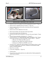
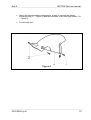
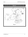
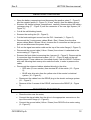
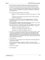
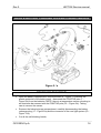
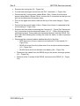
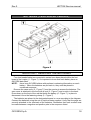
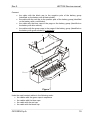
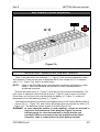
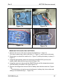
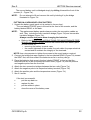
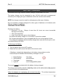
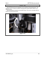
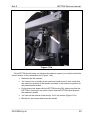
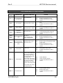
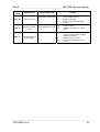
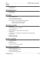
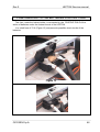
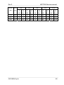
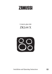
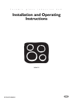
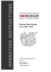
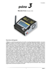
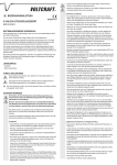
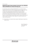
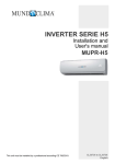
Rev.0 CE-DOT Service manual LEPTON LEPTON-e Freedom. By Choice. Rev.0 LEPTON Service manual INDEX INTRODUCTION.......................................................................................................................4 RECEIVING THE GOODS.......................................................................................................5 STORAGE ...................................................................................................................................5 DELIVERY TO THE FINAL CUSTOMER............................................................................6 INSTRUCTIONS FOR FILLING IN THE FORM “READY TO START” ............................6 MOTOR & MECHANICAL TRANSMISSION......................................................................7 REMOVING THE MOTOR ......................................................................................................8 MOUNTING THE ELECTRIC MOTOR ..................................................................................9 DRIVE & BATTERY CHARGER, LEAD SEALED BATTERIES VERSION ................11 REMOVING THE DRIVE.......................................................................................................12 MOUNTING THE DRIVE ......................................................................................................12 DRIVE & BATTERY CHARGER NI-ZN BATTERIES VERSION ..................................14 REMOVING THE DRIVE.......................................................................................................14 MOUNTING THE DRIVE ......................................................................................................16 BATTERIES ( LEAD SEALED VERSION ).........................................................................18 MOUNTING / REMOVING THE BATTERIES ...................................................................18 BATTERIES ( NI-ZN VERSION ) .........................................................................................20 MOUNTING / REMOVING THE BATTERIES ....................................................................20 BATTERY MANAGEMENT SYSTEM.................................................................................23 AUTONOMY INDICATORS ON THE SCOOTER...............................................................23 BATTERY CHARGER............................................................................................................24 HUMAN INTERFACE ............................................................................................................26 ELECTRONIC KEY INITIALIZATION ................................................................................26 THROTTLE..............................................................................................................................28 WIRINGS ..................................................................................................................................30 INSTRUCTIONS FOR USE AND INTERVENTION ON BATTERIES ...........................31 BATTERIES MAINTENANCE ..............................................................................................31 BRIEF NOTES ON USE OF LEPTON BATTERIES.............................................................34 ALARM OR ERROR MESSAGES ........................................................................................37 ALARM....................................................................................................................................37 ERROR.....................................................................................................................................37 TROUBLESHOOTING GUIDE .............................................................................................38 COUPONS .................................................................................................................................40 OPERATIONS COUPONS OF MAINTENANCE .................................................................40 OXYGEN S.p.A. 2 Rev.0 LEPTON Service manual LIST AND PROCEDURES OF CONTROLS.........................................................................41 FUSES ........................................................................................................................................44 FUSES ON LINE 230 VAC.....................................................................................................45 FUSE INSERTED TO THE BATTERIES POSITIVE POLE................................................46 SERVICES FUSE AND IGNITION FUSE .............................................................................47 FORELOADS <P> AND CLAMPING TORQUES <M> OF ISO METRIC THREAD SCREWS....................................................................................................................................48 OXYGEN S.p.A. 3 Rev.0 LEPTON Service manual INTRODUCTION OXYGEN S.p.A. would like to wish you a good job and hopes to be useful to you by providing this handbook. Please read carefully the information this document contains; in case of doubts or remarks about its contents contac us. Generally, in case the information are not enough for particularly complicated operations on a LEPTON we are at your complete disposal to supply the assistance you need. Lepton is a Z.E.V. vehicle (zero emission vehicle), it respects the environment and the current regulations concerning polluting emissions of the vehicles. This manual indicates the main points for LEPTON maintenance and it is supplementary to the Use and Maintenace Manual and to the Warranty Manual. So before reading this document it is necessary to read the information containerd in the Use and Maintenance Manual and in the Warranty Manual. In this manual are examined the components peculiar of the electric scooter, for interventions on the devices usually used on endothermic scooters such as: • Tyres • Shock absorbers • Fairing • Lights • Break levers • Frame • Others… It is necessary to refer to the normal rules of intervention. WARNING! Any work carried out on the vehicle during the warranty period by any person other than authorized OXYGEN personnel shall result in the warranty becoming void. OXYGEN S.p.A. reserves the right to make any change to its models at any time, though the essential characteristics described and illustrated herein remain unaltered, and therefore declines liability for any errors encounterd in the manual as a result of said changes. OXYGEN S.p.A. 4 Rev.0 LEPTON Service manual RECEIVING THE GOODS On receiving the Lepton check the packaging is not damaged or broken, otherwise do not accept it, motivating the refuse and communicating it as soon as possible to OXYGEN. When removing the packaging, pay attention to the following instructions: • Use the proper tools to remove all the metallic clips; • Remove the carton around the handlebar; • Open the carton on the side up paying attention not to scratch the fairing of the scooter and taking off the packaging; • Remove the nylon cover always paying attention not to scratch the fairing of the scooter. After removing the packaging, chek the following parts: • Plastic fairing, painted and not painted; • Lights and mirrors; • Motor and driver; • Tyres; • Suspensions; For Lepton Pb the battery voltage must be higher than 50 Volt. If it is between 46 Volt and 50 Volt make a complete recharge as soon as you can, if lower than 46 Volt contact OXYGEN at once. For Lepton Ni-Zn the battery voltage must be higher than 48 Volt. If it is between 44 Volt and 48 make a complete recharge as soon as you can, if lower than 44 Volt it is necessary to charge and recharge the batteries about 10 times untill a sufficient autonomy of the vehicle is reached. In case this procedure is not successful contact OXYGEN as soon as you can. STORAGE Keep the Lepton away from heating and from direct irradiation. Besides, do not keep the Lepton or its spare parts in wet spaces. IMPORTANT : Every two months at the latest, chek the voltage of the battery pack and recharge the LEPTON completely. Before this operation chek the battery voltage. If this is between 46 Volt and 54 Volt recharge completely, if lower than 40 Volt contact OXYGEN as soon as you can. OXYGEN S.p.A. 5 Rev.0 LEPTON Service manual DELIVERY TO THE FINAL CUSTOMER The vehicle is ready for starting: it is a very important operation and must be made very carefully. LEPTON is a product where particolar attention is given to the quality of its components and to their assembling. Anyway, during packaging, storaging, transport, moving and receiving of the vehicle, damages to the components might occur. INSTRUCTIONS FOR FILLING IN THE FORM “READY TO START” Before delivering the LEPTON to the Customer it is necessary to make a careful chek, filling in the form “Warranty/Product Registration Card” contained in the Warranty Manual. OXYGEN S.p.A. 6 Rev.0 LEPTON Service manual MOTOR & MECHANICAL TRANSMISSION The Electric motor (1 - Figure 1) is attached to the side of the transmission chainguard (2 - Figure 1) with 4 screws. Figure 1 The entire motor is connected to the frame by means of a special splinter bar (3 Figure 1) with two screws (4 - Figure 1). NOTE: The electric motor cannot be separated from the transmission chain-guard. Doing so would compromise the correct functioning of the motor and possibly damage the motor’s control system. Thus, the electric motor must be changed as a unit. OXYGEN S.p.A. 7 Rev.0 LEPTON Service manual REMOVING THE MOTOR • • • • • • • • • • • • • • Remove the helmet storage compartment, being careful to disconnect the battery recharger plug (17 - Figure 5) and the connector of the rear light system (19 - Figure 5). Cut the thermal sheath from the Z10-1 connectors (1 - Figure 5); Unscrew the 3 connectors in order to pull out and disconnect the power cables (1 – Figure 5); Disconnect the 3 motor power cables (black/red/green) from the drive power cables (black/brown/blue); Disconnect the ground cable (yellow/green) from the motor case (2 - Figure 5); Pull out the signal connection cable with the corresponding connectors from the hole in the motor flange (4 - Figure 5). Unscrew all the screw 3 in (Figure 4) to allow the rotation of the mudguard, in order to facilitate the dismantlement of the rear wheel; Get off the rear wheel; After getting off the rear wheel, get off the brake jaw, the ogive of the jaw and the ogive lever because these will be mounting into the new motor; Disconnect the sheath of the rear brake wire; Disconnect the rear shock absorber from the motor leaving screwed the upper parts; Disconnect the splinter bar and the motor from the frame (3 – Figure 1) by unscrewing the two fastening screws (4 - Figure 1).); Dismantle all the rear mudguard unscrewing the 2 residual screws (2 – Figure 4); Disconnect the splinter bar of the motor unscrewing the 4 block screws (3 – Figure 1). OXYGEN S.p.A. 8 Rev.0 LEPTON Service manual Figure 2 Figure 3 MOUNTING THE ELECTRIC MOTOR • Attach the motor to the splinter bar with the appropriate screws (3 - Figure 1); • Attach the rear mudguard with only 2 screw (2 – Figure 4); • Attach the splinter bar and the motor to the frame with the 2 appropriate screws (4 – Figura 1); • Attach the rear shock absorber to the motor; • Mount the jaw brakes, the ogive jaw and the ogive brake; • • Connect the sheath of the rear brake wire; Connect the cable with the connector to the top of the motor frame(4 - Figure 5); Connect the ground cable (yellow/green) (2 - Figure 5); Connect with the Z10-1 clamps the motor power cables(Black / Red / Green) to the cable coming out of the DRIVE (Black / Brown / Blue) (1 - Figure 5); • • o RED wire from DRIVE with RED motor wire o BLACK wire from DRIVE with BLACK motor wire o BLUE wire from DRIVE with GREEN motor wire • Cover the Z10-1 clamps with heat-restringent covers employ a phon in order to covering completely the connectors. In absence of the thermal shealth, employ a insulating adhesive; • Mount the rear wheel; • Fix the rear mudguard (3 – Figure 4); • Test the motor; • Group all the motor cables and the main cables with self blocking bands like under the interventions; OXYGEN S.p.A. 9 Rev.0 LEPTON Service manual • Mount the helmet storage compartment supply to connect the battery recharger plug (17 – Figure 5) and the connector of the rear light system (19 – Figure 5); • Functionality test . Figure 4 OXYGEN S.p.A. 10 Rev.0 LEPTON Service manual DRIVE & BATTERY CHARGER, LEAD SEALED BATTERIES VERSION Figure 5 OXYGEN S.p.A. 11 Rev.0 LEPTON Service manual REMOVING THE DRIVE • • Open the battery compartment and disconnect the positive poles (7 - Figure 5) and the negative poles (8 - Figure 5) (10 mm2 section) from the battery group; Remove the helmet storage compartment, carefully disconnecting the battery recharger plug (17 - Figure 5) and the connector of the rear light system (19 Figure 5); • Cut all the self-blocking bands ; • Remove the cooling fan (18 - Figure 5); • Cut the heat-restringent covers from the Z10-1 terminals (1 - Figure 5) • Disconnect the 3 motor power cables (Black / Red / Green) from the drive power cables (Black / Brown / Blue), unscrew the 3 connectors so that you can pull out and disconnect the power wires; • Pull out the signal connection cable on the top of the motor flange(4 - Figure 5); • Disconnect the ground cable (Yellow / Green) from where it is attached to the motor casing (2 - Figure 5); • Remove the front shield unscrewing the 4 screws (9 – Figure 5). Disconnect the 3 connectors from the electrical system (10 / 11 – Figure 5) and cut the selfblocking band. These cables are connected directly with the DRIVE. Pull them with care following their runway site under the frame, in order to preserve the cable; • Disconnect the wires and cables attached directly to the drive: o RED wire (10 mm2 section) from terminal 87 of the switch (12 – Figure 5); o BLUE wire drive wire from the yellow wire of the scooter’s electrical system (16 – Figure 5); • Disconnect the cables from the DRIVE plug to the electric recharge system (21 – Figure 5) ; • Remove all the 2 screws of the DRIVE, and remove the DRIVE (0 – Figure 5). MOUNTING THE DRIVE • Place the drive near the motor; • Connect the signal cable from the drive in the appropriate connector on the top of the motor flange (4 – Figure5); • Connect the ground cable (Yellow / Green) from DRIVE to the motor casing (2 - Figure 5); OXYGEN S.p.A. 12 Rev.0 LEPTON Service manual • Attach the drive to the frame brackets carefully after having placed all the wires from the drive inside the frame itself, without blocking the screws; • Connect the 2 signal cables with the electrical system into the front shield (10/11 – Figure 5), taking care that this cables should be insert and block to the frame ( under the footboard, like originally ). Blocking the 2 cables with self-blocking band; • Connect the wires attached directly to the DRIVE; o RED wire (10 mm2 section) from terminal 87 of the switch (12 – Figure 5); o BLUE wire drive wire from the yellow wire of the scooter’s electrical system (16 – Figure 5); • Positioning the NEGATIVE pole with the fastening clamp (8 – Figure 5) across the frame in order to bring near the NEGATIVE pole of the battery pack with the pin; • Fixing completely the DRIVE to the frame brackets (0 – Figure 5), then fixing the cooling fun (18 – Figure 5) with the correct gradient; • Connect with the Z10-1 clamps the motor power cables(Black / Red / Green) to the cable coming out of the DRIVE (Black / Brown / Blue) (1 - Figure 5); o RED wire from DRIVE with RED motor wire o BLACK wire from DRIVE with BLACK motor wire o BLUE wire from DRIVE with GREEN motor wire • Cover the Z10-1 clamps with heat-restringent covers employ a phon in order to covering completely the connectors. In absence of the thermal shealth, employ a insulating adhesive. Then grouping the 3 cables and block with self-blocking bands to the near frame bracket, tacking care that this clamping will not block the normal oscillation of the rear fork , and the rear fork will not pull the cables from the motor; • Functionality test; • Group all the motor cables and the main cables with self blocking bands like under the interventions; • Mount the helmet storage compartment supply to connect the battery recharger plug (17 – Figure 5) and the connector of the rear light system (19 – Figure 5); • Mount the front shield; • Functionality test; OXYGEN S.p.A. 13 Rev.0 LEPTON Service manual DRIVE & BATTERY CHARGER NI-ZN BATTERIES VERSION Figure 5 / a REMOVING THE DRIVE • Open the battery compartment, remove the bar (4 – Figure 7). Remove the plastic protection of the battery pack , disconnect the POSITIVE pole (7 – Figura 5/a) from the batteries. NOTE: there is a temperature sensor mounting to an aluminum bar connect with the POSITIVE pole (22 – Figure 5/a). Taking care to remove the sensor. • Remove the helmet storage compartment, carefully disconnecting the battery recharger plug (17 - Figure 5/a) and the connector of the rear light system (19 Figure 5/a); • Cut all the self-blocking bands; OXYGEN S.p.A. 14 Rev.0 LEPTON Service manual • Remove the cooling fan (18 - Figure 5/a); • Cut the heat-restringent covers from the Z10-1 terminals (1 - Figure 5/a); • Disconnect the 3 motor power cables (Black / Red / Green) from the drive power cables (Black / Brown / Blue), unscrew the 3 connectors so that you can pull out and disconnect the power wires; • Pull out the signal connection cable on the top of the motor flange(4 - Figure 5/a); • Disconnect the ground cable (Yellow / Green) from where it is attached to the motor casing (2 - Figure 5/a); • Remove the front shield unscrewing the 4 screws (9 – Figure 5/a). Disconnect the 3 connectors from the electrical system (10 / 11 – Figure 5/a) and cut the self-blocking band. These cables are connected directly with the DRIVE. Pull them with care following their runway site under the frame, in order to preserve the cable; • Disconnect the wires and cables attached directly to the drive: o RED drive wire (10 mm2 section) from terminal 87 of the switch (12 – Figure 5/a); o BLUE drive wire from the yellow wire of the scooter’s electrical system (16 – Figure 5/a); o BLACK drive wire from the black wire battery (8/a – Figure 5/a) • Disconnect the cables from the DRIVE plug to the electric recharge system (21 – Figure 5/a); • Remove all the 2 screws of the DRIVE, and remove the DRIVE (0 – Figure 5/a). OXYGEN S.p.A. 15 Rev.0 LEPTON Service manual MOUNTING THE DRIVE • Place the drive near the motor; • Connect the signal cable from the drive in the appropriate connector on the top of the motor flange (4 – Figure5); • Connect the ground cable (Yellow / Green) from DRIVE to the motor casing (2 - Figure 5); • Attach the drive to the frame brackets carefully after having placed all the wires from the drive inside the frame itself, without blocking the screws; • Connect the 2 signal cables with the electrical system into the front shield (10/11 – Figure 5), taking care that this cables should be insert and block to the frame ( under the footboard, like originally ). Blocking the 2 cables with self-blocking band; • Connect the wires attached directly to the DRIVE; o RED wire (10 mm2 section) from terminal 87 of the switch (12 – Figure 5); o BLUE wire drive wire from the yellow wire of the scooter’s electrical system (16 – Figure 5); • If it’s present, cut the fastening clamp to the BLACK wire from the DRIVE (8 – Figura 5) and remove 10 mm of the plastic coverage. Connect the wire with the screw contact (8/a – Figure 5/a) coming to the NEGATIVE pole o fthe battery pack (8 – Figura 5/a); • Fixing completely the DRIVE to the frame brackets (0 – Figure 5/a), then fixing the cooling fun (18 – Figure 5/a) with the correct gradient; • Connect with the Z10-1 clamps the motor power cables(Black / Red / Green) to the cable coming out of the DRIVE (Black / Brown / Blue) (1 - Figure 5); o RED wire from DRIVE with RED motor wire o BLACK wire from DRIVE with BLACK motor wire o BLUE wire from DRIVE with GREEN motor wire • Cover the Z10-1 clamps with heat-restringent covers employ a phon in order to covering completely the connectors. In absence of the thermal shealth, employ a insulating adhesive. Then grouping the 3 cables and block with self-blocking bands to the near frame bracket, tacking care that this clamping will not block the normal oscillation of the rear fork , and the rear fork will not pull the cables from the motor; • Connect the POSITIVE pole (7 – Figure 5/a) and the temperature sensor (22 – Figure 5/a) on the POSITIVE pole of the battery pack, take care that the temperature sensor will not be damaged ( to know the correct fixing power to practice on the screw contacts of the Ni-Zn batteries, read carefully the OXYGEN S.p.A. 16 Rev.0 LEPTON Service manual “OPERATING INSTRUCTION FOR MAINTENANCE FREE SEALED NI-ZN BATTERIES” manual supplied with the scooter ); • Functionality test; • Group all the motor cables and the main cables with self blocking bands like under the interventions; • Mount the helmet storage compartment supply to connect the battery recharger plug (17 – Figure 5) and the connector of the rear light system (19 – Figure 5); • Mount the front shield; • Functionality test; OXYGEN S.p.A. 17 Rev.0 LEPTON Service manual BATTERIES ( LEAD SEALED VERSION ) Figure 6 MOUNTING / REMOVING THE BATTERIES Four lead sealed batteries connected in series have been placed within the foot board of the Lepton (1 - Figure 7). It’s important to know that each battery have an OXYGEN data label. NOTE: there is an OXYGEN sticker with pertinent numbering information on each battery. When the batteries are put back in, they must be placed in numbered sequence. Remove the case cover (2 - Figure 7) from the scooter to access the batteries. The case cover is attached in the front with a lock (3 - Figure 7) and a notch in the back. Press down on the front of the rod that holds the battery (4 - Figure 7), in place to disconnect it from the fastening clamp (5 - Figure 7) The batteries are placed in the designated space in a row according to the diagram. Connect the batteries using the set of rapid contacts supplied. Verify that the pegs are correctly attached to the terminals of the batteries. Remember that each contact must be made between a negative and positive pole in the sequence listed. OXYGEN S.p.A. 18 Rev.0 LEPTON Service manual Connect: • the cable with the black cap to the negative pole of the battery group (identified on the battery with a black sticker). • the cable with the red cap to the positive pole of the battery group (identified on the battery with a red sticker). • the cable with the blue caps to the pegs on the battery group (identified on the battery with blue sticker). • the cables with the green caps to the pegs of the battery group (identified on the battery with green stickers) in sequence. 2 3 4 5 1 Figure 7 Undo the rapid contact cables in the following order: • the cables with the green caps in sequence • the cables with the blue caps • the cable with the red cap • the cable with the black cap OXYGEN S.p.A. 19 Rev.0 LEPTON Service manual BATTERIES ( NI-ZN VERSION ) Figure 7/a MOUNTING / REMOVING THE BATTERIES There is an area within the footboard (1 – Figure 7) that accommodates the nickelzinc batteries. There are two sets of batteries that in turn contain two 12 V batteries each (1 / 2 – Figure 7/a), held in a metal frame. NOTE: There is an OXYGEN sticker with pertinent numbering information on each battery. When the batteries are put back in, they must be placed in numbered sequence. Remove the case cover (2 - Figure 7) from the scooter to access the batteries. The case cover is attached in the front with a lock (3 - Figure 7) and a notch in the back. Press down on the front of the rod that holds the battery (4 - Figure 7), in place to disconnect it from the fastening clamp (5 - Figure 7) The batteries are placed in positive and negative sets on the second battery pack (2 –- Figure 7/a) (3 – Figure 7/a), and via the two bridges that connect the two cells (4 / 5 – Figure 7/a). The batteries contain a total of 48 volts (Figure 7/a). WARNING! In some cases the positive (+) and negative (–) poles are reversed in respect to their placement in the diagram (Figure 7/a) on the following page, so clean the terminals to certify that the red (positive) cable is connected to the red terminal and the black (negative) cable is connected to the black battery terminal. OXYGEN S.p.A. 20 Rev.0 LEPTON Service manual Figure 7/b Figure 7/c Figure 7/d Figure 7/e REMOVING THE NICKEL-ZINC BATTERIES 1. Remove the cover of the case to access the batteries (2 – Figure 7). The case is secured by a lock at the front (3 – Figure 7), and a notch at the back. 2. Press down to unhook the metal rod (4 – Figure 7) holding the battery in place (5 – Figure 7). 3. Using the appropriately-sized tool, disconnect the NEGATIVE pole from the battery, black cable with the lug on the left (Figure 7/b). 4. Using the same tool, disconnect the POSITIVE pole and the temperature sensor from the battery red cable on the right (Figure 7/c). 5. Remove the bridges that connect the two battery sets with the same tool (Figure 7/d). The first battery unit can be moved at this point, holding it by its two sides and sliding it out toward the top (1 – Figure 7/a). OXYGEN S.p.A. 21 Rev.0 LEPTON Service manual The second battery unit is dislodged simply by sliding it toward the front of the scooter (2 – Figure 7/a). NOTE: Do not attempt to lift and remove this unit by holding it by the bridge illustrated in Figure 7/e. PUTTING IN A NEW NICKEL-ZINC BATTERY 1. Unpack the battery pack (each unit is packed in its own box). The one labeled FRONT goes in the well at the front of the scooter, and the battery labeled REAR, at the back. NOTE: The replacement battery packs always contain the connection cables as well. They include the main insulation bridge (Figure 7/d) and two smaller insulation bridges (Figure 7/e). Always use the new parts when changing the batteries. • Refer to the OPERATING INSTRUCTIONS FOR MAINTENANCE FREE SEALED NI-ZN BATTERIES manual that comes with each battery pack for instructions on: o removing the battery terminal caps o the correct tightness of the screws for each cable for proper electrical contact and to maintain the integrity of the terminals. NOTE: Use a torquemeter to tighten the screws to the exact tension required. 2. Connect the bridge that was supplied in the box labeled REAR (Figure 7/d) toward the SEAT first, and then slide in the batteries as far in as they can go. 3. Place the batteries that came in the box labeled FRONT in front so that the terminals that are to be connected face each other (Figure 7/e) and the positive and negative poles face the front fork. 4. Attach the two connection bridges between the two units (Figure 7/e). 5. Attach the negative pole to its respective battery terminal (Figure 7/b) 6. Attach the positive pole and the temperature sensor (Figure 7/c) 7. See if it works. • • • • If the test is successful, put the cap back on replace the bar put the cables in place close the cover of the battery case. OXYGEN S.p.A. 22 Rev.0 LEPTON Service manual BATTERY MANAGEMENT SYSTEM AUTONOMY INDICATORS ON THE SCOOTER The LEPTON scooter has a series of visual LCD indicators on the control panel that indicate the scooter’s charge remaining in terms of kilometers. This calculation is based on an algorithm that estimates remaining energy and average use. The estimate is calculated in terms of the difference between Ah stored during the recharge and Ah expended during its use. NOTE: In the event that the vehicle is not in use for a long period of time, the remaining charge estimate could be erroneous. To avoid this error, the scooter must be completely recharged. Average use is calculated on the basis of the driver’s riding style and the road conditions. The calculation is derived from measurements taken during the last 45 seconds that the scooter was in use. Therefore, with a certain charge, the following assumptions can be made: • On a level road, the remaining charge would be about 45 km. • On a hill, the average consumption would be greater, thus the remaining charge lower, for example, around 25 km. The charge remaining would increase once again if the scooter returned to a level road. • On a descent, average consumption would be low, and so the remaining charge would be high, for example, around 60 km. The remaining charge would decrease if the scooter returned to a level road. • On a level road, the charge in the batteries would diminish on account of the consumption of energy. Thus, the estimate of remaining charge diminishes in direct relationship to kilometers driven. As illustrated, the remaining charge indicated can vary greatly even in a short period of time, when the charge contained in the battery actually does not change substantially. The reserve battery low energy light begins to blink when the amount of charge remaining in the batteries is only sufficient to cover less than 15 km. The reserve battery low energy light stays lit when the amount of charge remaining in the batteries is only sufficient to cover less than 10 km. NOTE: If the reserve battery low energy light is activated, and the remaining charge shown is greater than the distance just given as examples, have the light checked. OXYGEN S.p.A. 23 Rev.0 LEPTON Service manual BATTERY CHARGER The scooter has a high frequency battery charger incorporated in the drive. The battery charger can be connected to any 110-Volt outlet and is programmed exclusively for charging the type of batteries used in the scooter automatically. NOTE: the charger cannot be used for recharging any other type of battery. Do not use battery chargers designed for other types of batteries or for batteries with different voltages or capacities. CHARGING THE BATTERIES Recharge the battery: • whenever it is low. Delays of more than 24 hours can cause irreversible damage to the battery. • often and completely • even if you have only gone a short distance Only allow the battery charge to run out when it cannot be avoided. Do not leave the batteries in an uncharged state for even a short period of time. Only charge the batteries with the battery charger that came with the bicycle or with one authorized by OXYGEN. To Recharge the Battery 1. Turn the ignition key to the OFF position. 2. Raise the seat, and connect the cable to the electric outlet. A flashing or steady light (depending on the battery charge status) on the instrument panel indicates that the battery recharger is in use. • • • • Rapid flashing: Slow flashing: Fixed light: Light off: first phase second phase third phase end of charge/buffer phase The scooter cannot be started while the battery is being charged. The drive is automatically placed in stand by mode and the abbreviation stby appears on the LCD strip of the speedometer. While the batteries are recharging, do not touch the drive. The surface temperature could reach 140 degrees Fahrenheit. OXYGEN S.p.A. 24 Rev.0 NOTE: LEPTON Service manual In order not to compromise battery performance, the batteries should be recharged or changed, when the residual charge indicated on the LCD strip of the instrument panel is about 5 Km. Below that threshold, the system that reads the state of charge left in the batteries may not be able to determine with accuracy the actual charge/number of residual kilometers remaining. CAUTION: When charging the batteries, verify that the current and voltage are correct. It is not true that energy can be added to a completely charged battery. Furthermore, the lead-acid AGM batteries can be ruined electronically if over charged. The electrolyte water is converted into hydrogen and oxygen and produces considerable heat, and the battery could explode. OXYGEN S.p.A. 25 Rev.0 LEPTON Service manual HUMAN INTERFACE ELECTRONIC KEY INITIALIZATION LEPTON scooter is equiped with an electronic key ( Figure 9). The key includes the DRIVE identification code (TRANSPONDER key ). Every key can authorize only the LEPTON connected with this DRIVE identification code. In order to make the scooter starting, You have to insert the key correctely into the connector. The connector is placed on the left side of the legshield (Figure 8). If the scooter do not start, the message “CODE” appears on the dashboard LCD (8 – Figure 11) and the RED light on the upperframe goes on blinking ( 5 – Figure 11). Figure 8 Figure 8/a Figure 9 Figure 10 OXYGEN S.p.A. 26 Rev.0 LEPTON Service manual Figure 11 If you loose or damage the electronic key so that the LEPTON cannot start, you need to initialize the DRIVE in order to use a new different electronic key. The new key is supplied directly by OXYGEN. To install the new key, use the following instructions: • • • • • • • • Turn OFF the LEPTON; Insert the MASTER KEY (Figure 10) into the connector placed on the left side of the legshield (Figure 8); Turn ON the LEPTON; The initialization phase is starting so that the message “CODE” will appear on the dashboard LCD (8 - Figure 11); Let the scooter stay on this state at least for 30 seconds. Now the DRIVE is initialized; Turn OFF the LEPTON; Take off the MASTER KEY. Insert the new key ; Turn ON the LEPTON. During this phase the DRIVE read the new code of the key and set the starting connected with the new key. Figure 8/a shows the device that recognizes the electronic key. The device is binded to the legshield. It reads the data key and comunicates with the DRIVE. NOTE : sometimes happens that the substitution key shows a different plastic cover. This difference does not influence the usual working of the initialization sequence. OXYGEN S.p.A. 27 Rev.0 LEPTON Service manual THROTTLE The LEPTON throttle acts a resistence value variations of the potentiometer. This resistence value is read by the DRIVE, that gives the required electric power to run with the scooter. The potentiometer is inside the front shield (Figure 11/a) and is connected with the throttle by a retrieval spring wire. Figure 11/a OXYGEN S.p.A. 28 Rev.0 LEPTON Service manual Figure 11/b If the LEPTON throttle does not achieve the maximun speed, you need to check the correct tension of the connection wire (Figure 11/a): • Dismantle the front shield; • You have to turn a throttle at the maximum rotation point, then check that the maximum position of the throttle coincides to the maximum position of the potentiometer braket; • Do the same test again with the LEPTON turning ON, taking care that the LEPTON is leaving on the stand. Check that the LEPTON could achieve the maximum speed. • You can set the stretch of the wire by the 2 set screws (Figure 11/b). • Block the 2 set screws and mount the shield. OXYGEN S.p.A. 29 Rev.0 LEPTON Service manual WIRINGS LEPTON has three kinds of wirings: • Power wiring: (batteries-DRIVE, motor-DRIVE, relè-DRIVE) particular care must be used when replacing or reparing them because of their high voltage. In particular, uncorrected connections might cause localized heating thus compromizing the safety of the vehicle and the correct functioning of LEPTON’S main components. • Wirings for auxiliary systems: ( lights, acoustic signal,etc…) refer to the normal rules of intervention. • Control wiring: it tranfers the signals between the main components (DRIVE-dashboard, accelerator-DRIVE, handlebar comands-DRIVE, motor sensors-DRIVE, battery temperature sensors-DRIVE ver. Ni-Zn). Possible oxidations on the contacts points of the connectors or an uncorrected inserting of the same might cause serius bad functioning of the vehicle. OXYGEN S.p.A. 30 Rev.0 LEPTON Service manual INSTRUCTIONS FOR USE AND INTERVENTION ON BATTERIES BATTERIES MAINTENANCE • • • • • • All of the materials used in the lead-acid AGM batteries are resistant to the corrosive action of the acid. Lead-acid AGM batteries are virtually maintenance free if used in the proper manner. The lead-acid batteries use a diluted sulfuric acid solution that has been applied to a micro fiberglass felt-like material for the electrolyte. The battery housing is completely sealed. No leakage of battery acid is possible. The batteries should never be opened. They do not need additional fluid. It is unnecessary to grease the exposed parts of the bicycle with petroleum jelly. NOTE: • Grease on the battery terminal posts decreases contact between the batteries and the connection cable. It also impedes the delivery of energy. Thus, it should be avoided. Simple, regular maintenance will keep the batteries in proper working order. Battery Inspection • There should be no evidence of damage or cracks in the batteries. • The battery terminals should never have wrinkles, bumps, or burns. If there are any present, do not use the batteries. Battery Cleanliness • • • • Sponge off the battery with warm water and a little household detergent, if necessary. Do not immerse the battery in water. Do not clean the batteries with abrasives or solvents that could damage the plastic battery housing. The battery terminals should be cleaned with a copper wire brush and appropriate tools. OXYGEN S.p.A. 31 Rev.0 LEPTON Service manual Temperature Constraints • Low temperatures hinder battery performance. Battery Handling • Never lift the batteries by the terminals. • Do not stack one battery on top of another. Stacking might cause them to collapse. New Batteries • There is no need to “break in” new batteries. After thirty charging cycles, the cells reach their maximum level of performance. Battery Life • The performance of a battery diminishes after it has reached a certain age, and it must be replaced. NOTE: Dispose of the batteries in an environmentally-responsible manner. CAUTION: • • The battery is an energy source. If that energy is released in an uncontrolled way, for example, through a short circuit, serious damage can result. For reasons of safety, do not eat, drink, or smoke near the batteries. Even though the battery cells are sealed, handle them with care. If battery acid should come into contact with skin or clothing, immediately wash with soap and cold running water. • • • Keep the batteries away from heat and open flames. If the battery fluid contains a higher concentration of hydrogen and oxygen than normal, it could burst into flames. Do not touch the battery while it is charging or discharging. OXYGEN S.p.A. 32 Rev.0 LEPTON Service manual Working on the Batteries • • • • • • Only OXYGEN service technicians can work on the batteries. Handle the batteries with care to avoid damaging them. Check the battery connections. Use the proper tools when working on batteries. Avoid placing tools on the battery while working on it. Do not wear rings, bracelets, wristwatches, or metal buckles while working on batteries. • Do not run batteries in closed areas. • Do not disconnect the battery recharger before the battery has been completely recharged; this might happen intentionally or unintentionally if the battery recharger is connected to an electric system which utilizes reduced rates at different times of the day thereby interrupting the power output. It is recommended that the batteries be completely recharged upon consignment. OXYGEN S.p.A. 33 Rev.0 LEPTON Service manual BRIEF NOTES ON USE OF LEPTON BATTERIES The battery is influenced by the way of use. The battery is a “variable” tank. If you take as a reference an internal combustion vehicle you know that the higher the average speed, the more the driving is unsteady (strong accelerations), the heaviest the loads (people and goods), the greatest the kilometric consumption. The same is for the batteries of any kind of electrochemical pair. In order to increase the autonomy it is necessary to run accurately the energy of the elettrochemical accumulators avoiding abrupt accelerations and brakings, or acceleration when standing at the traffic light. The battery performance is influenced by temperature. In internal combustion vehicles the differences are very slight also because the functioning temperature of the motor is higher than the external one. In the batteries instead, chemical and elettrochemical reactions which supply electric energy do not develop heating significantly , so the battery is influenced by the environment temperature. The decrease of performance can be significant, you can suppose a decrease of performance, under the same conditions of use, even of 50% between +30°C and 0°C. To be precise, the temperature of reference is that inside the battery. The thermic exchange with the environment is limited by the thermic protection given by the plastic material which hold the same. It is advisable to keep it “warm”, charging it, if possibile, in warm environment so that to begin to use the vehicle with the battery warmer than the temperature outside. In this way, the autonomy of the vehicle will be influenced in an unconsiderable way by the environment temperature. Keep the battery charged. Lead-acid and Nichel-Zinc battteries must be kept charged the more you can. They require a recharge as soon as possibile, even for short periods of time and even if uncompletely. The time of life of the battery is influenced by its use. The deeper the battery discharge, the less the accumulator can bear cycles of charge and discharge. Besides, this relation is not linear, for instance by halving the depth of discharge, the endurance – measured in numbers of cycles of charge and discharge – becomes more than the double. On the whole, the battery will supply more energy , this is to say more run kilometers before it has to be replaced. So it is advisable to avoid deep descharges and recharge the vehicle after using it every time. OXYGEN S.p.A. 34 Rev.0 LEPTON Service manual The charge of the battery is a very important aspect. The quality of the current supplied by the battery charger and the kind of charge are very important for a good performance and for the time of life of the batteries. Currents and/or too much high voltages, excessive endurances or insufficient charges damages the battery, and surely they influence the next performance. At present, you can find on the market “hermetic batteries”, more correctedly said “at valve regulator gas recombination”; they fit very well for application on electric vehicles for lack of maintenance, which is required instead by Pb traditional batteries and by Nichel-Cadmio batteries. Gas recombination batteries offer a high compatibility , have a very reduced gas emission (until 10 times less than the traditional free electrolyte batteries) besides, in case of breaking of their holder do not release corrosive liquids as it happens instead with the other batteries. Unfortunately this kind of batteries requires recharging curve according to the specifications provided by the batteries producers. If the curve are not correct the batteries might be damaged for an excess of a defect of recharge. So it is important to recharge the LEPTON batteries with the battery charger provided or expressly approved by OXYGEN. How to check the batteries. Operations of control must be made by experts who know the vehicle well. The batteries, even if not connected to the vehicle, are “active” objects anyway and a shortcircuit can create dangerous situations. With the “hermetic” batteries it is not possible to control the density of the electrolyte just because of how they are produced, which is the traditional method of check of the charge state and health state of free electrolyte batteries. In this case the only necessary control that can be made is the check of the tension of every single battery composing the battery pack. Make this control at least half an hour after the end of charging, using a voltmeter to read the tensions at the terminals, checking either the absolute value and its homogeneity inside the group. To be considered charged, lead acid and Nichel-Zinc batteries must have at the clips a tension not lower than 12.70 Volt (batteries with a nominal tension of 12 Volt); lower values indicate clearly an insufficient charge. Tensions higher than 13.40 Volt can indicate an overcharged battery; but before giving a definitive judgement, in this case it is necessary to repeat the measurement at least three hours after the end of charging, and it is necessary however to check the functionality of the battery charger. The difference of the tensions between the modules of the battery must be contained within 0.2 Volt, higher values indicate an unbalanced battery pack. Warning: different temperatures of battery might influence the evaluation of dishomogeneity. The batteries need maintenance. Even if the batteries are defined “without maintenance” it is necessary to carry out some operations of control rather than of maintenance. Check regularly the tightening of screws and clips, always using insulated tools, as the loosening between two components made of different metals is usual, having the OXYGEN S.p.A. 35 Rev.0 LEPTON Service manual metals different thermal expansion. The decreasing of the quality of the contact means a decreasing of the motor voltage. Further more it means an overheating of contact parts and a loosing of the seal between the plastic case and the contact itself. The consequence might be a gas leak out of control. Keep the batteries clean using a dry cloth, so that not to generate current dispersion and lack of insulation. The vehicle in case of prolonged storage. Either Lead acid and Nickel-Zinc batteries, as described above, prefer a high state of charge. Also in this situation it is recommended to recharge the batteries completely before keeping the vehicle unused for some time. In case of prolonged periods of time it is advisable to eliminate all the loads/absorptions by disconnecting, if possible, the battery after recharging it. In case the vehicle is kept unused for more than one month it is advisable to recharge it using the internal battery charger. If this procedure is not respected, irreversible damages might occur to the batteries. WARNING: Ni-Zn LEPTON can recover its initial performance by making a series of repeated charges and discharges (circa 10). Never mix different types of batteries. This means that if a module is defective it is necessary to replace the whole battery pack. This recommendation is due to the fact that the batteries are charged in series; this means that the battery charger is piloted by the total tension of the battery and not by the tension of the single module; the deriving risk is to have some modules overcharged and some other in phase of recharge thus causing a great unbalance in the battery. Thinking of the modules as connected in series, you can imagine the battery as a chain composed of as many rings as the elettrochemical elements (6 in a battery of 12 Volt). The charge supported by the chain is that of its weakest element. The same is for the battery, the performance is piloted by the weakest element. Each of the batteries composing a pack is marked by a progressive serial number. OXYGEN S.p.A. 36 Rev.0 LEPTON Service manual ALARM OR ERROR MESSAGES The LCD strip on the instrument panel shows any breakdowns or malfunctions. They are subdivided into Alarm and Error categories. ALARM The Alarm category indicates temporary breakdowns or malfunctions that allow the rider to continue travelling, even if the conditions are not optimal. The letters “All…” appear for 5 seconds every 20 seconds. ERROR The Error category indicates permanent malfunctions that might block the vehicle and that, therefore, require specialized assistance in resolving the problem. The letters “Err…” appear until the problem has been resolved. OXYGEN S.p.A. 37 Rev.0 LEPTON Service manual TROUBLESHOOTING GUIDE ALARM TYPE DESCRIPTION ALL 4 Motor temperature first high level ALARM CONDITIONS Exceeding of the fixed motor temperature Real values of temperature Break of temperature sensor Problems with electronic card of control Hard use of the scooter on the way down Problems with electronic card of control ERR 1 Over Voltage Value of voltage over 70V Intervention time = 60 ms ERR 2 Under Voltage Default value = 20 V Intervention time = 400 ms ERR 3 ERR 4 (only NiZn) ERR 5 ERR 7 ERR 10 Default high level = 75°C Dissipator Intervention time 1 s temperature high anl low level Battery temperature high Set to 50° C. Work only during the battery-charging phase Default level value =140°C Default level low = 25°C Motor temperature second high and low Intervention time 1 s level Current Alarm Current Alarm ERR 11 OXYGEN S.p.A. Low level energy inside the battery Problems with electronic card of control Dissipator over temperature ( environmental causes, hard use) Problems with electronic card of control Real value of temperature Break of temperature sensor Problems with electronic card of control Real values of temperature Break of wiring of temperature sensor on the motor Break of temperature sensor Problems with electronic card of control Too much elevated current on the motor Current value over the set point of 1° for a time longer than 100 ms in phase 1 or Current value over 8,12A for a time longer than 100 ms in phase 2 or Current value over the set point of 1A for a time longer than 100 ms in phase 3 Voltage value over 70V in buffer for a time longer than 1s Current value over 2A for a time longer than 2s No signal from Hall Sensor Processor Error CAUSES Break of MOSFET Wiring phase wrong motor Problems with electronic card of control Failure batteries Failure of battery charger Problems with electronic card of control Wrong wiring of Hall Sensor on the motor or break of wiring Break of Hall Sensor Problems with electronic card of control 38 Rev.0 ALARM TYPE LEPTON Service manual DESCRIPTION ERR 12 Tuned of motor ERR 14 Overtime of battery charger ALARM CONDITIONS CAUSES Wrong sequence of configuration of Hall Sensor Active when the recharge time exceeds the time limit ERR 16 Over temperature of battery charger OXYGEN S.p.A. Wrong wiring of Hall Sensor on the motor or break of wiring Break of Hall Sensor Problems with electronic card of control Failure of battery Problems with electronic card of control Excessive overheating of the battery charger ( environmental conditions, break of the battery ) Failure of battery charger Problems with electronic card of control 39 Rev.0 LEPTON Service manual COUPONS For a correct functioning of the vehicle and to prevent a bad functioning or an early deterioration of the batteries or of the control electronics devices, we advise to make periodical controls, referring to the following table for times, maximum runs, and list of controls for each intervention on the vehicle: For further information read carefully the Warranty Handbook. Oerations made by any person other than authorized OXYGEN personnel shall result in the warranty becoming void. OPERATIONS COUPONS OF MAINTENANCE n° COUPONS OPERATIONS n° 0 Km= 0 0 months SHOCK ABSORBER C FORK C MOTOR UNTIE C STAND C WHEELS BEARING C STEERING C BRAKES C TRANSMISSION OIL C TYRES C BOLTS BLOCKING C TRANSMISSION BELT C BATTERIES C ELECTRICAL SYSTEM C BATTERY CHARGER C ELECTRICAL INSULATION C ELECTRONIC INSTRUMENTS C VEHICLE TEST C VEHICLE DOCUMENTATION C VEHICLE CLEANING C BEFORE THE DELIVERY OF THE VEHICLE C FEATURING OF THE VEHICLE C n° 1 Km= 500 4 months n° 2 Km=4000 12 months n° 3 Km=8000 18 months n° 4 Km= 12000 24 months n° 5 Km= 16000 30 months n° 6 Km= 20000 36 months C C C C C C C C C C C C C C C C C C C C C C C C C C C C C C S C S S C S C C C C C C S C C C C C C C C C C S C C C C C C C S C C C C C C C C C C C C C C C C C C C C C C C C C C C C C C C = check and possible replacement of the wasted part S = replacement OXYGEN S.p.A. 40 Rev.0 LEPTON Service manual LIST AND PROCEDURES OF CONTROLS REAR SHOCK ABSORBER Wavering functionality and oil leak Stroke FORK Wavering functionality and oil leak Stroke ENGINE SUPPORT Wavering functionality Blocking screws STAND Functionality WHEELS BEARING Stroke and damages Sliding Noises STEERING Steering slide Steering-lock functionality BRAKES Lever stroke set Integrity of transmission wire. Check functionality TRANSMISSION Oil level OXYGEN S.p.A. 41 Rev.0 LEPTON Service manual TYRES Correct pressure Check tyres TRANSMISSION BELT Check usury Check tension BATTERIES Check integrity shell Check contacts screws block Check the single tension module Check connection and stroke among the batteries o Rapid contacts (LEAD-Acid model); o Screws contacts (Ni-Zn model). ELECTRICAL SYSTEM Start button Check potentiometer functionality Sprint mode button Indicators switch. Indicator lights. Indicator lamps Mode button Headlight switch. Headlight light. Headlight lamp. Dashboard light. Horn button Battery charger light Battery reserve light BATTERY CHARGER Functionality test Check fan Electric insulation Integrity check of wires and cables ELECTRONIC INSTRUMENT Ignition Key: ON/OFF. Check the dashboard chek-up Check LCD indications Check electronic key reading OXYGEN S.p.A. 42 Rev.0 LEPTON Service manual VEHICLE TEST Manageabling and stability Front brake Rear brake Check functionality residual energy Check motor brake Check throttle (free movement). Chek noises and waver running VEHICLE DOCUMENTATION Control the presence of vehicle documentations (Owner’s manual, Warranty,… ) Check frame serial number ( if existing) Check batteries serial number Check motor serial number Check Drive serial number Under the vehicle delivery Clean the vehicle Check keys functionality Mounting accessories or dismount parts Customer delivery Read, subscribe and explain the product informative The owner shall subscribe the “OWNER INFORMATION RELEASE CARD” Compile all parts and subscribe the “WARRANTY/PRODUCT REGISTRATION “ Aesthetics vehicle Painting Plastic combining Scratch OXYGEN S.p.A. 43 Rev.0 LEPTON Service manual FUSES In the LEPTON there are some protections to the main circuits which are composed of fuses; they are connected in series to these circuits to protect the electronics of the vehicle and the batteries Before working on these devices, pay attention to the following precautions: BE SURE THAT WHEN REPLACING ANY ONE OF THE FUSES THE LEPTON IS OFF OR THAT THE RECHARGE PLUG IS NOT INSERTED; IN CASE OF REPLACEMENT, NEVER USE FUSES DIFFERENT FOR FORM OR AMPERAGE FROM THE ONES SHOWED. IN CASE THIS PROCEDURE IS NOT RESPECTED, OXYGEN DOES NOT TAKE ANY RESPONSIBILITY FOR DAMAGES TO THINGS OR PEOPLE. OXYGEN S.p.A. 44 Rev.0 LEPTON Service manual FUSES ON LINE 230 VAC These fuses are connected to the circuit of the connection plug to the net 230 VAC for the scooter recharge ( 20 – Figure 5). They are two fuses 230V - 6,3 A format 5X20, inserted inside the two cases (Figure 12); you reach the fuses by lifting the saddle of the LEPTON. These fuses work in case of short-circuits inside the LEPTON with reference to the power circuit of the battery charger, or in case the cooling fan of the DRIVER is damaged or in short-circuit. Figure 12 OXYGEN S.p.A. 45 Rev.0 LEPTON Service manual FUSE INSERTED TO THE BATTERIES POSITIVE POLE This fuse, under the helmet holder, is connected to the POSITIVE POLE of the series of batteries under the footrest tunnel of the LEPTON. It is a belt fuse of 70 A (Figure 13) and prevents possibile short-circuits of the batteries. Figure 13 OXYGEN S.p.A. 46 Rev.0 LEPTON Service manual SERVICES FUSE AND IGNITION FUSE These two fuses, under the helmet holder, protect respectively the power circuit of the LEPTON services ( lights, alarms, etc.... ) and the control circuit of ignition of the LEPTON. They are made as a fork and have a value of 7,5 A (Figure 14). SERVICES STARTING Figure 14 OXYGEN S.p.A. 47 Rev.0 LEPTON Service manual FORELOADS <P> AND CLAMPING TORQUES <M> OF ISO METRIC THREAD SCREWS Every intervention related to mechanical aspects of OXYGEN products shall consider the clamping torques of nuts and screws. This paragraph collects the set of rules in force of ISO metric thread screws. If there are no other explanations than OXYGEN instruction and user manuals, it is necessary to refer to what is scheduled in the following table about foreloads and clamping torques. The following table describes diameters and pitches, clamping coefficients K, foreloads P, and clamping torques M of the most of nuts and screws. K coefficients and the related clamping torques M are set approximately with reference to the following terms and conditions: • Exagonal-head screws (UNI 5737-65 model), cylindrical-head screws with embedded exagon (UNI 5931-67 model), cylindrical-head screws with notch (UNI 6107-67 model) • Friction coefficient is considered 0,14 and it is valid for all processed burnished and oiled surfaces • Clamping torques is made slowly using dinamometric-keys All other terms and conditions, per each fixed foreload value, changing K coefficient, change tha clamping torque. Clamping torques can be given as follows: • Exagonal-head screws for metal structural work (UNI 5712-65 model): the clamping torque M shall increase of 5% • Zinced screws: clamping torques M shall reduce of 10% • Cadmium plated screws: clamping torques M shall reduce of 20% • Automatic screw-driver: clamping torques M shall reduce of 10% OXYGEN S.p.A. 48 Rev.0 LEPTON Service manual Table 1. : Foreloads P and clamping torques M of ISO metric thread screws. dxp Sr mm mm² 4.8 5.8 8.8 10.9 12.9 F M F M F M F M F M kN N·m KN N·m kN N·m kN N·m kN N·m 3x0,5 5,03 1,2 0.9 1.5 1.1 2.3 1.8 3.4 2.6 4.0 3.0 4x0,7 8.78 2.1 1.6 2.7 2.0 4.1 3.1 6.0 4.5 7.0 5.3 5x0,8 14.2 3.5 3.2 4.4 4.0 6.7 6.1 9.8 8.9 11.5 10.4 6x1 20.1 4.9 5.5 6.1 6.8 9.4 10.4 13.8 15.3 16.1 17.9 7x1 28.9 7.3 9.3 9.0 11.5 13.7 17.2 20.2 25 23.6 30 8x1.25 36.6 9.3 13.6 11.5 16.8 17.2 25 25 37 30 44 8x1 39.2 9.9 14.5 12.2 18 18.9 27 28 40 32 47 10x1.5 58 14.5 26.6 18 33 27 50 40 73 47 86 10x1.25 61.2 15.8 28 19.5 35 30 53 43 76 51 91 12x1.75 84.3 21.3 46 26 56 40 86 59 127 69 148 12x1.25 92.1 23.8 50 29 62 45 95 66 139 77 163 14x2 115 29 73 36 90 55 137 80 201 94 235 14x1.5 125 32 79 40 98 61 150 90 220 105 257 16x2 157 40 113 50 141 76 214 111 314 130 368 16x1.5 167 43 121 54 150 82 229 121 336 141 393 18x2.5 192 49 157 60 194 95 306 135 435 158 508 18x1.5 216 57 178 70 220 110 345 157 491 184 575 20x2.5 245 63 222 77 275 122 432 173 615 203 719 20x1.5 272 72 248 89 307 140 482 199 687 233 804 22x2.5 303 78 305 97 376 152 592 216 843 253 987 22x1.5 333 88 337 109 416 172 654 245 932 286 1090 24x3 353 90 383 112 474 175 744 250 1060 292 1240 24x2 384 101 420 125 519 196 814 280 1160 327 1360 27x3 459 119 588 147 703 230 1100 328 1570 384 1840 OXYGEN S.p.A. 49 Rev.0 LEPTON Service manual dxp Sr mm mm² 4.8 5.8 8.8 10.9 12.9 F M F M F M F M F M kN N·m KN N·m kN N·m kN N·m kN N·m 27x2 496 131 615 162 760 225 1200 363 1700 425 1990 30x3.5 561 144 772 178 955 280 1500 399 2130 467 2500 30x2 621 165 859 204 1060 321 1670 457 2370 535 2780 OXYGEN S.p.A. 50 Rev.0 LEPTON Service manual OXYGEN S.p.A. Via Ponticello, 44 - 35129 Padova Tel. +39 (0) 49 8282311 - Fax. +39 (0) 49 8079871 Sito internet: www.oxygenworld.net - E-mail: [email protected] OXYGEN S.p.A. 51