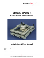
1
SP002 / SP002-R
MANUAL SCREEN-/STENCILPRINTER
Installation & User Manual
For:
Part-Nr.:
Version:
Author:
Checked:
Release Date:
SP003 / SP003-V
SPMASP-SP003-E
1.1
01.04.2007
Essemtec AG • Mosenstrasse 20 • CH-6287 Aesch/LU • Switzerland
Phone: +41 (0)41 919 60 60 • Fax: +41 (0)41 919 60 50 • [email protected] • www.essemtec.com
Installation & User manual
SPMASP-SP002-E
Version 2.1
Page 2 of 19
Datum:01.02.2005
Your machine has been produced to the highest standard and all functionality has been fully tested before delivery.
The operation of this machine is very simple; still we strongly recommended that you read through this entire
manual before operating any part of this machine. If you have any additional questions which are not answered in
this manual, please contact us.
ESSEMTEC
Mosenstrasse 20
CH - 6287 Aesch / LU
Switzerland
Tel. ++41/(0)41 919 60 60
Fax. ++41/(0)41 919 60 50
Email [email protected]
Web www.essemtec.com
or your nearest ESSEMTEC distributor:
Further information about Screen and Stencil Printing; Fully Automatic, Manual and Half Automatic Pick and Place
Machines; Dispensing Systems and also Reflow Soldering Systems can be found on our Internet Site:
www.essemtec.com
SPMASP-SP002-E
Version 2.1
Page 3 of 19
Datum:01.02.2005
Installation & User manual
You have opted for an ESSEMTEC Screen-/Stencilprinter. We thank you for this decision and congratulate to it.
Base specification all models
5
2.
Unpacking
5
3.
List of options
5
4.
Details
6
5.
Adjustment possibilities
7
5.1.
Height adjustment / On all models
5.1.1.
Practical advice for height adjustment
5.2.
Gas-Spring loaded opening of upper frame / On all models
5.2.2.
Adjusting of balancing mechanism:
6.
PCB Fication
6.1.
6.2.
6.3.
6.4.
7.
9
All models
Fixation on model B / Flat Base Plate
Fixation on model V / Vacuum table
Fixation of PCB on model G / Groove table
9
9
9
9
Adjusting the PCB
7.1.
7.2.
7
7
7
8
10
With base models
With option SP002-3 registration frame
10
10
8.
Applying solder cream
11
9.
Printing
11
9.1.
9.2.
9.3.
10.
10.1.
10.2.
10.3.
10.4.
10.5.
11.
11.1.
11.2.
Squeegee angle
Printing speed
Choosing the proper squeegee
11
11
11
Printing with squeegee guidance (Option SP002-..R)
Assembly instruction for retrofit option SP002-….R
Adjustment of print head height:
Adustment of printing force
Adjustment of braking force
Maintenance of guided squeegee
12
13
14
14
14
14
Hints and tips for screen / stencilprinting
15
Soldercream
Some tips for good result with solder pase printing
15
15
12.
Vertical Separation (Option)
16
13.
Schablonenbeschreibung SPGEN-12 Spannrahmen
17
14.
Maintenace advice
18
CE-DECLARATION OF CONFORMITY
SPMASP-SP002-E
19
Version 2.1
Page 4 of 19
Datum:01.02.2005
Installation & User manual
1.
Base specification all models
Baseplate for PCB’s:
420 x 340mm
Max. size screen frames:
435 x 355mm (standard)
500 x 355mm (option: SP002-1)
Max. height of PCB:
40mm (standard)
Fixation of screen frames:
with screws into screen frame (4 x M6 or M8)
Needed tablespace:
680 x 600mm
Weight:
depending the model between 25 and 35 Kgs.
Opening upper frame:
with gas spring
Upgradeabilities:
all manual models can be upgraded at a later stage with the guided squeegee
option SP002-R)
2.
Unpacking
Please check before unpacking the system if any transportation damage is visible on the outside of the packacking.
If any damage is visible, please inform immediately your freight forwarder.
Your system is delivered according to your ordered specifications. Basically it consists of the following parts:
•
•
Base system with standard accessories (toolset, on models with squeegee guidance: handle for guidance and
double squeegee set)
ordered Accessories (squeegees, registration frame, etc.)
Please put the base unit onto a stable table.
The system was already adjusted in our factory. Neverthless as there are many differences in weight in screen and
stencilframes on the market, some readjustments may be necessary. Please follow the directions in the forthcoming
chapters.
3.
List of options
For the SP002 Printers a number of helpfull accessories are available.
SPMASP-SP002-E
Version 2.1
Page 5 of 19
Datum:01.02.2005
Installation & User manual
1.
Details
1.
Adjustment PCB plate in x-direction
2.
Adjustment PCB plate in y-directio U turning both knobs in the same direction) or adjustment of rotation
(turning only one knob)
4.
Joint of upper frame, is released when upper frame is lowered onto supports (8)
5.
Height adjustment supper frame bacckside (rough alignment)
6.
Adjustment of the screenframe holder bar
7.
Adjustment of the screenframe holder screws (according to customers screenframe, usually M6 or M8
screws
8.
Heightadjustments upper frame backside (fine-adjustment)
9.
Fixations of height adjustment screws
10.
Heightadjustments upper frame frontside (fine-adjustment)
11.
Fixations of height adjustment screws
12.
Adjustment bars for frontside height screws
Installation & User manual
4.
13.-16. Gasspring construction for opening support upper frame
SPMASP-SP002-E
Version 2.1
Page 6 of 19
Datum:01.02.2005
Adjustment possibilities
5.1.
Height adjustment / On all models
The gap of the upper frame to the base plate, resp. from the PCB surface to the screen/stencil bottom side is an
important parameter for proper printing results.
To adjust this distance, the following steps have to be made:
1.
2.
3.
4.
5.
6.
7.
Lay the screenframe or the stencil tension frame into the printer and close the upper frame
Open the screws (5) with the in the delivery included tool
Loose all fixations of the height adjustment (9, 11)
Attach the screenframe or stencil tension frame on the rails (6, 7)
Adjust the height of all 4 hieght adjustment screws (8, 10) / see also advice in chapter 5.2) and fix the height
with the fixation (9, 11)
Important:
The balls of the frontside height adjustment screws (10) have to fit precisly into the bars
(12) to ensure a high repetitivity during printing operation
Tighten the screws (5)
You may check by light tapping onto upper frame if the upper frame is laying on all 4 supports
5.1.1. Practical advice for height adjustment
Basically, in working with screens the difference between screen and PCB surface should be around 0,5 to 1,5mm.
This in contrast to stencil printing where the stencil has to lay directly on the PCB.
To calculate the correct distance you can easliy so this according to the following formula:
Length of the used squeegee in mm multipled be 0.005
In practical work this difference may vary slightly due to different squeegee angles and pressures. Try it out to get
the best printing results!
You may adjust the height even easier by using the optional available height wedge SP002-14.
5.2.
Gas-Spring loaded opening of upper frame / On all models
The base adjustment was made already in our factory. Due to construction details, the height adjustment has no
influence onto the gasspring, as the gas support is highered or lowered automatically at the same time.
When using heavy screen frames it might be possible that the gas loaded spring itself has to be readjusted. Please
make the following steps to do so.
SPMASP-SP002-E
Version 2.1
Page 7 of 19
Datum:01.02.2005
Installation & User manual
5.
13
14
15
16
Opening rod
locking nut M6
arm setting screw
locking nut of arm setting screw M 16x1.5
Basic adjustment is made at manufacturer’s plant.
Balancing force at closed frame can be increased by prolonging of opening rod 13
WARNING:
A complete loosing of this rod may cause injury due to the air spring shock expanding
.
•
•
•
Loose the lockin gnut 14
By turning with the opening rod 13 adjust the required length (always check for the required opening force of
the upper frame – frame must sit in closed position by it’s weight on all four points.
fis the locking nut 14
The increase of the opening force during opening and thus the final balancing force by open frame can be adjusted
by prolonging of the arm by arm setting screw 15.
WARNING:
Acomplete loosing of this rod may cause injury due to the air spring shock expanding
.
•
•
•
Loose the lockin gnut 16
turn the arm setting screw into required position (do it by the opened upper frame and always check the
balancing force to be enough to hold upper frame open)
fis the locking nut 14
SPMASP-SP002-E
Version 2.1
Page 8 of 19
Datum:01.02.2005
Installation & User manual
5.2.2. Adjusting of balancing mechanism:
Balancing mechanism has following items for adjustment:
PCB Fication
6.1.
All models
PCB’s are placed on the base plate of the SP002 so the pads are almost in accordance with holes of the
sccreens/stencils. Undepending the base plate type (B,V or G) we strongly recommend that the surounding areas
are also covered with empty PCB’s or PCB material of the same thickness. This is preventing during printing the
damage of the screens or stencils at the edges of the PCB and ensures a long life of your screens/stencils.
Example:
6.2.
Fixation on model B / Flat Base Plate
The easiest way is to fix the surounding PCB material with doublesided adhesive tape. In this way you establish a
kind of mask where you can simply lay into the PCB which has to be printed.
6.3.
Fixation on model V / Vacuum table
Same procedure as on model B. Use also surounding PCB’s for preventing damges on screens and stencils.
Additionaly the same material is used to cover the vacuum holes.
The vacuum plate is usually used for bended or flexible, thin PCB’s as they are hold properly into position due to
vacuum suction.
The commection for the vacuum is below the printer. Optional availble is an extemal vacuum pump.
6.4.
Fixation of PCB on model G / Groove table
With the within the groove slideable plates with fixing pins almost every position of a PCB can be defined by using
the pinholes of a PCB. Therefore no adhesive tapes are encessary on this model. Neverthless also here it is
recommended to use surounding PCB material to prevent damages o your screen or stencils.
WARNING:
Please make sure that the pins are NOT higher then the PCB. Damages on screen/stencil
may occur if they do so.
SPMASP-SP002-E
Version 2.1
Page 9 of 19
Datum:01.02.2005
Installation & User manual
6.
Adjusting the PCB
7.1.
With base models
After inserting the PCB into the printer (according to chapter 6), slightly press the screen onto the PCB and check if
the pads of the PCB are fitting the holes of the screen. With the adjustment screws for x/y and rotation axis (1,2) the
fine adjustment can be made.
Using stencils it is not necessary to press down as it already lays on the PCB surface.
7.2.
With option SP002-3 registration frame
Printing critical pads (i.e. Pine-Pitch) resp. for arranging the printer much faster, the option SP002-3 registration
frame (also know as test printing frame) was developed.
Application:
•
•
•
•
•
•
•
•
attach the PCB to the foreseen position on the base plate
put the registration frame with the 4 bins into the previewed holes
close the upperframe of the printer
print directly, without readjusting the x/y-axis onto the registration frame
open printer and you seenow the actual done printing on the special, acidresistant foil of the registration frame
now you may readjust the printer in x/y- and rotation axis in a very precise manner with the actual printed
solder cream
take away the registration frame and you may clean it
now you may start immediately with printing
The 4 height supports of the upper frame ensure the high repetability and ensures now a printing cycle without any
readjustments.
SPMASP-SP002-E
Version 2.1
Page 10 of 19
Datum:01.02.2005
Installation & User manual
7.
Applying solder cream
Apply a sufficient amount of solder cream about 5-10cm behind the first openings of the PCB onto the screen or
stencil
Makesure you apply a sufficient amount over the complete lenght of the squeegee, resp. printing width.
(See also hints and tips within chapter 10)
9.
Printing
9.1.
Squeegee angle
With the manual SP002 devices manual squeegees with 75 shore squeegee hardness are delivered, which ensure an
ideal manual printing. To achieve a proper printing it is recommended to hold the squeegee in an angle of 45°.
On models with the guided squeegee the angle of 45° is already given. The hardness of the squeegees are 85 Shore
as there is more pressure applied due to the mechanics.
9.2.
Printing speed
The squeegee speed must provide a slow rolling of the soledercream infront of the squeegee rubber. If the speed is
too fast not all holes will be filled with soldercream. The speed is depending the consistency of the used solder
cream, which can vary upon age, temperature and supplier.
9.3.
Choosing the proper squeegee
The length of squeegee has to be equal, or at least not much longer, than the width of the printed substrate. If not
so, the squeegee blade tends to bend on the BCB and the cleaning of the stencil surface from the paste cannot be
uniform (thus resulting in non-uniform layer).
SPMASP-SP002-E
Version 2.1
Page 11 of 19
Datum:01.02.2005
Installation & User manual
8.
Installation & User manual
10. Printing with squeegee guidance (Option SP002-..R)
Printing with a squeegee guidance is offering the advantage to work user independent as squeegee pressure and
angle are provided mechanically by the machine. Only the speed can be varied by the operator. The results are
more repetitive and better printing results.
Additionally the squeegee guidance is equipped with a double squeegee which allows to print back and forth
without appliying new soldercream. It enhances therefore the printing speed and ensures that the SP002 can even
be used beside fully automatic pick-and place systems for midsize production runs.
If desired with the separate adjustable squeegee pressure floating/printing jobs can be done easily (i.e. the holes are
filed in one direction with a floating pressure and are then printed onto the PCB board in a second strike with more
pressure)
Due to pull/push on the handle a brake is automatically released. This brake is used when opening the
upper
SPMASP-SP002-E
Version 2.1
Page 12 of 19
Datum:01.02.2005
For cleaning the squeegee, the complette squeegee guidance can be simply tilted out on one side (depending the
side the guidance was mounted)
10.1. Assembly instruction for retrofit option SP002-….R
If retrofitted, You get following parts:
•
•
•
•
•
Squeegee mechanisms head with lateral rods and brake
guiding rod 3 with holders 4
control handle 1
pair of screws for mounting of the holders of of guiding rod 5
pair of wqueegees with trailing edge of chosen length (130, 220 or 300 mm) 6
Assembly instruction
1.
2.
3.
4.
5.
6.
7.
8.
remove one guiding rod holder 4 (loosing screw and pulling the holder from the rod 3)
slide the head with lateral rods and brake onto the guiding rod. Be carful on the proper sense of headto guiding orientation. The guiding squeegee set is fully symmetrical and You can obtain a
configuration with guide on right side, or left side of the machine. Thus You can make the machine
ergonomically for both right – and left- hander.
put the previously removed guide holder 4 back on the guiding rod 3. Do not fix it yet.
pull out two of rubber linders (most front and most rear) on that side of the upper frame on which You
want to mount the gliding rod
remove both M5 screws under the rubber plugs
mount the guided squeegee assembly by means of two special screws 5. Before final fixing is
important to check if the motion of guided sueegee is parallel with table surface and adjust if if
necessary.
close the guided squeegee assembly – the opposite side to the guiding rod 3 is guided with both
rollers form upper side and gliding spots from lower side of the rectangular guide rod. To achieve this,
pull the black knob 8 and move the whole head down so that the both rollers touch the rectangular
rod.
for mounting, celaning and exchange of squeegees pull the knob 8 and tilt the head with lateral rods
to the required position (there is an optional support of opened squeegee assembly available)
SPMASP-SP002-E
Version 2.1
Page 13 of 19
Datum:01.02.2005
Installation & User manual
frame so the squeegee guidance can not move.
Resulting of occasion using different type of printing border and fashion their fastening. before adjustment it has to
be upper frame of screen printer to the upper frame of screen printer to the right position against DPS or printing
subject and both squeegees set on and adjust in the height position. For adjusting of height head is in the
accessories of screen printer plastic plate diameter 4 mm.
•
•
•
•
•
Loose 4 screws M3 holding dampers on the external corners of slide blocks printing head.
Printing table lif to height position – it is only in model uniprit – lift
Setting plastic diameter underlay under both squeegee in their middle so that sreen printer with printing table
S, V and G, you put it on the face of table, concept M constitute it on placing backing plate, like foundation DPS.
Squeegee, rubber or metal, put bottom edge on setting board. Be carreful!
Damper in the corners of slide blocks gradually lift when the botton indoor edge of bottom flute touch peg. In
this position you habe to fasten down screws M3.
10.3. Adustment of printing force
Each squeegee has its own mechanism for adjustment. The force can be adjustet with ribbed nut on each side of
squeegee head. When proper adjusted, squeegee has to clean the surface of the metal micomask fully, but not to
scrape-out the solder cream form apertures of mask. Squeegee is balanced, no other adjustment is necessary.
10.4. Adjustment of braking force
A squeeegee head has a brake on the front/rear gliding, which stops and locks the position of head just after the
operator’s hand let it stay in any position. The braking force must be enough to keep the head in its position even
when frame is opened. Proper adjustment is done at manufacturer, if the readjustment after some time will be
neeeded, check for the proper function of breaking rubber stone and loose, or tight the nut of its rod proprietary.
10.5. Maintenance of guided squeegee
The guided squeegee is virtually maintenance-free. All bearings and gliding are self-lubricated/Teflon lined.
Do not lubricate giding rod 3! – the brake will than loose its efficiency. Keep the mechnism clean and prevent any
spillage with solder cream. If dirty, clean smoothly with alcohol or isopropanol.
Do not work on dry stncil, or screen (i.e. without solder cream or glue on it) – the friction forces are too high, you risk
a serious damage of your masks. All bearings of guided squeegee assembly are exposed to higher forces, which
speeds up their wearing.
SPMASP-SP002-E
Version 2.1
Page 14 of 19
Datum:01.02.2005
Installation & User manual
10.2. Adjustment of print head height:
11.1. Soldercream
Here some advices out of practice to help you achieving good printing results:
•
•
•
•
•
•
Use only soldercream which is intended to be used on screen/stenscilprinters
store soldercream below 25°C, to store the solder cream the longest possible period it is recommended to store
it between 8° and 10°C.
Before using the soldercream bring it to room temperature and open the can only when room temperature is
reached.
Soldercream you already used within the printer must not be put back into the can/glas
the smalles opening on your stencil, resp. the smallest mesh should be not under the 7times size of the solder
ball. For Fine-Pitch applications special solder cream is available with smaller solder balls. Ask your solder cream
supplier for further in formations
Apply a sufficient amount of soldercream onto the screen/stencil to ensure proper rolling and printing quantity
11.2. Some tips for good result with solder pase printing
1. Printig Gap
good value is 0,005 x printing stroke length
2. The Squeegee
we provide 75hsH for manual squeegee(yellow) and 85hsH for guided squeegee(white).
The harder is suitable for metal micro-etched masks, the softer for emulsion masks.
3. he Printing Pressure on the guided squeegee can be set step-less from 10N to 50N. You can see a good
adjusted pressure directly on the mask – it has to be cleaned fully from the solder paste,
but the solder paste must not be wiped-out from bigger openings in the mask.
4. The Squeegee/Table Print Angle
basic setting during action is 60°. The bigger angle does not allow the solder paste to
come through the mask fully, the smaller makes a too big pressure of the paste and causes
dirty screen from lower side, thus not correct printing.
5. The Squeegee Speed depends on paste rheology. Paste should always be rolling in front of the squeegee. Too
high speed makes print uncompleted.
6. Keep the lower face of the screen always clean.
7. The smallest opening in the mask (or screen mesh) should be not smaller, than 7diameters of the solder paste
ball.
8. Never open the solder cream jar before coming to the room temperature.
9. Never mix the new and used solder cream in the same jar.
SPMASP-SP002-E
Version 2.1
Page 15 of 19
Datum:01.02.2005
Installation & User manual
11. Hints and tips for screen / stencilprinting
This modification is equipped by pneumatic lifting of screen printer table controlled by hand valve placed in the
front between knobs.
The lifting of screen printer table is 3mm The print is always made in the upper position and by letting down of the
table is smudge of the printing motive by stencil prevented. Other procedures are the same as for Uniprint.
There is needful supply of the compressed air mas. t bar, the pressure is controllableby regulation valve – placed
form behind the screen printer.
The speed of lifing of the table is to set by the fhrottle valve on the output of the regulator. The speed of letting
down is to set by the throttle valve placed in the front right corner of the bottom farme.
Important: The overly throttled valve of the compresssed air causes uneven letting down or lifting of the table.
Setting of appropriate speed of the table is recommended.
Maintenance: no special maintenance reqauired.
Function is as follows:
1.
Insert a PCB
2.
Bring the printing table in its
upward position
3.
Lower the stencil onto the board
4.
Print
5.
Bring the printing table in its
lower position (= vertical separation)
6.
Open the upper frame and
take out the PCB
The separation speed can be additionally adjusted by a valve on the right side of the printer.
SPMASP-SP002-E
Version 2.1
Page 16 of 19
Datum:01.02.2005
Installation & User manual
12. Vertical Separation (Option)
Installation & User manual
13. Schablonenbeschreibung SPGEN-12 Spannrahmen
Min. 142mm
Max. 462mm
Max. 500mm
M8
M8
142mm to 462mm
Max. 500mm
M8
M8
SPMASP-SP002-E
Version 2.1
Page 17 of 19
Datum:01.02.2005
Practically all guidances are dry guided and must therefore not be maintained. Prevent soldercream on the
guidances and keep your machine always clean.
Only the guidance of the x/y-baseplate must be greased once per year with high quality grease.
SPMASP-SP002-E
Version 2.1
Page 18 of 19
Datum:01.02.2005
Installation & User manual
14. Maintenace advice
Machine SR:
98/37/CE
Manufacturer
ESSEMTEC AG
Adress of Manufacturer
ESSEMTEC AG
Mosenstrasse 20
CH – 6287 Aesch LU
Switzerland
We herewith declare, that the mentioned machines are in conformity with the above
stated standards and healthy and safety rules of the CE directives.
If there are any changes on the machine as also on their options by the user/customer, this declaration will expire
immediately.
Typ:
Screen- and Stencilprinter
SP002-M / ML
SP002-G / GL
SP002-V / VL
SP002-B / BL
Accessories:
all
Serial number:
__________________
Date of manufacture:
__________________
Applied/used harmonised
european norms:
EN60204-1,EN292-1,EN292-2,EN1050, EN894-3,
EN294, EN62079, EN953, EN983
ESSEMTEC AG
Aesch, _______________
Martin A. Ziehbrunner
Director
SPMASP-SP002-E
Version 2.1
Page 19 of 19
Datum:01.02.2005
Installation & User manual
CE-DECLARATION OF CONFORMITY