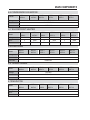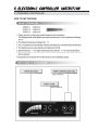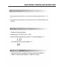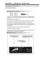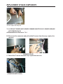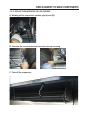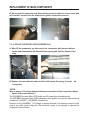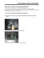
1
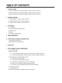
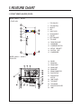
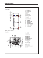
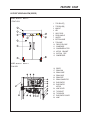
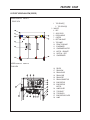
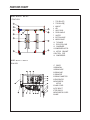
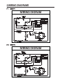
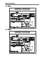
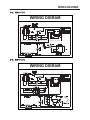
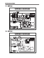
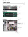
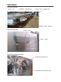
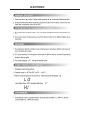
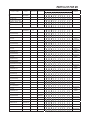
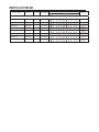
CAUTION! PLEASE KEEP POWER SWITCH ON BEFORE OPERATING THIS EQUIPMENT Turbo Air Speed up the Pace of Innovation Commercial Refrigerator & Freezer Service Manual Please read this manual completely before attempting to install or operate this equipment! M3 Series SOLID DOOR / GLASS DOOR M3R24-1 M3R47-2 M3R72-3 M3R24-2 M3R47-4 M3R72-6 M3F24-1 M3F47-2 M3F72-3 M3F24-2 M3F47-4 M3F72-6 www.turboairinc.com TABLE OF CONTENTS 1. FEATURE CHART 1-1.FRONT VIEW/PLAN VIEW (1DDOR):M3R24-1 M3R24-2 M3F24-1 M3F24-2 1-2.FRONT VIEW/PLAN VIEW (2DDOR):M3R48-2 M3R48-4 M3R48-2 M3R48-4 1-3.FRONT VIEW/PLAN VIEW (3DDOR):M3R72-3 M3R72-6 M3F72-3 M3F72-6 2. WIRING DIAGRAMS 2-1. 1DDOR: M3R24-1 M3R24-2 M3F24-1 M3F24-2 2-2. 2DDOR: M3R48-2 M3R48-4 M3R48-2 M3R48-4 2-3. 3DDOR: M3R72-3 M3R72-6 M3F72-3 M3F72-6 3. PART DETAIL 3-1. TOP GRILLE 3-2. REFRIGERATION COMPARTMENT 3-3.CONTROL BOX 3-4. DOOR 3-5.COOLING COMPARTMENT 4. MAIN COMPONENTS 5. ELECTRONIC CONTROLLER INSTRUCTION 5-1.FREEEZER CONTROLLER 5-2.REFRIGERATOR CONTROLLER 6. PARTS LIST 7. REPLACEMENT OF MAIN COMPONENTS 7-1 .TOP GRILLE PART 7-2. REPLACE DOOR 7-2-1κREPLACE DOOR (M3R24-1,M3F24-1,M3R47-2,M3F47-2,M3R72-3,M3F72-3) 7-2-2 . REPLACE DOOR (M3R24-2,M3F24-2,M3R47-4,M3F47-4,M3R72-6,M3F72-6) 7-3. REFRIGERATION COMPARTMENT’S PART. 7-3-1. REPLACE DUCT AND LAMP 7-3-2 . REPLACE T SENSOR AND D SENSOR 7-3-3. REPLACE THE EVAPORATOR COIL AND F-SENSER 7-3-4.REPLACE THE DEFROST HEATER (FREEZER ONLY) 7-3-5. REPLACE THE EVAPORATOR FAN MOTOR AND FAN BLADE 7-4. CONTROL BOX PART 7-5. CONDENSER UNIT 7-6. REPLACE THE CABINET HEATER AND MULLION HEATER 1.FEATURE CHART 1-1.FRONT VIEW/PLAN VIEW (1DOOR) MODEL: M3R24-1 M3F24-1 FRONT VIEW Freezer 1 2 3 4 5 6 7 8 9 10 11 12 13 14 15 TOP GRILLE(T) TOP GRILLE(B) MASCOT KEY ASS’Y DOOR DOOR HANDLE CASTER BOTTOM HINGE TOP HINGE FRONT PCB CASE CONDENSER CONDENSER MOTOR MOTOR BRACKET SUCTION PIPE COMPRESSER 16 17 18 19 20 21 22 23 DRYER DRAIN PAN DRAIN GUIDE DRAIN CASE DRAIN PIPE DRAIN CONNECTOR EVAPORATOR EVAPORATOR MOTOR LAMP COVER TOP GRILE T TOP GRILE B EVAPORATOR COVER LAMP MODEL: M3R24-1 M3R24-2 PLAN VIEW 24 25 26 27 28 FEATURE CHART MODEL: M3R24-2 M3F24-2 FRONT VIEW 1 2 3 4 5 6 7 8 9 10 11 12 13 14 15 16 TOP GRILLE(T) TOP GRILLE(B) MASCOT KEY ASS’Y DOOR DOOR HANDLE CASTER BOTTOM HINGE MIDDLE HINGE TOP HINGE FRONT PCB CASE CONDENSER CONDENSER MOTOR MOTOR BRACKET SUCTION PIPE COMPRESSER MODEL: M3R24-1 M3R24-2 PLAN VIEW 17 DRYER 18 DRAIN PAN 19 DRAIN GUIDE 20 DRAIN CASE 21 DRAIN PIPE 22 DRAIN CONNECTOR 23 EVAPORATOR 24EVAPORATOR MOTOR 25 LAMP COVER 26 TOP GRILE T 27TOP GRILE B 28EVAPORATOR COVER 29 LAMP FEATURE CHAR 1-2.FRONT VIEW/PLAN VIEW (2DOOR) MODEL: M3R47-2 M3F47-2 FRONT VIEW 1 2 3 4 5 6 7 8 9 10 11 12 13 14 15 TOP GRILLE(T) TOP GRILLE(B) MASCOT KEY ASS’Y DOOR DOOR HANDLE CASTER BOTTOM HINGE TOP HINGE FRONT PCB CASE CONDENSER CONDENSER MOTOR MOTOR BRACKET SUCTION PIPE COMPRESSER 16 17 18 19 20 21 22 23 DRYER DRAIN PAN DRAIN GUIDE DRAIN CASE DRAIN PIPE DRAIN CONNECTOR EVAPORATOR EVAPORATOR MOTOR LAMP COVER TOP GRILE T TOP GRILE B EVAPORATOR COVER LAMP MODEL: M3R47-2 M3R47-4 PLAN VIEW 24 25 26 27 28 FEATURE CHART MODEL: M3R47-4 M3F47-4 FRONT VIEW Freezer 1 TOP GRILLE(T) 2 TOP GRILLE(B) 3 MASCOT 4 KEY 5 ASS’Y DOOR 6 DOOR HANDLE 7 CASTER 8 BOTTOM HINGE 9 MIDDLE HINGE 10 TOP HINGE 11 FRONT PCB CASE 12 CONDENSER 13 CONDENSER MOTOR 14 MOTOR BRACKET 15 SUCTION PIPE 16 COMPRESSER MODEL: M3F47-2 M3F47-4 PLAN VIEW 17 DRYER 18 DRAIN PAN 19 DRAIN GUIDE 20 DRAIN CASE 21 DRAIN PIPE 22 DRAIN CONNECTOR 23 EVAPORATOR 24EVAPORATOR MOTOR 25 LAMP COVER 26 TOP GRILE T 27TOP GRILE B 28EVAPORATOR COVER 29 LAMP FEATURE CHAR 1-3.FRONT VIEW/PLAN VIEW (3DOOR) MODEL: M3R72-3 M3F72-3 FRONT VIEW Freezer 1 TOP GRILLE(T) 2 TOP GRILLE(B) 3 MASCOT 4 KEY 5 ASS’Y DOOR 6 DOOR HANDLE 7 CASTER 8 BOTTOM HINGE 9 TOP HINGE 10 FRONT PCB CASE 11 CONDENSER 12 CONDENSER MOTOR 13 MOTOR BRACKET 14 SUCTION PIPE 15 COMPRESSER MODEL: M3R72-3 M3R72-6 PLAN VIEW 16 17 18 19 20 21 22 23 24 25 26 27 28 DRYER DRAIN PAN DRAIN GUIDE DRAIN CASE DRAIN PIPE DRAIN CONNECTOR EVAPORATOR EVAPORATOR MOTOR LAMP COVER TOP GRILE T TOP GRILE B EVAPORATOR COVER LAMP FEATURE CHART MODEL: M3R72-6 M3F72-6 FRONT VIEW Freezer 1 TOP GRILLE(T) 2 TOP GRILLE(B) 3 MASCOT 4 KEY 5 ASS’Y DOOR 6 DOOR HANDLE 7 CASTER 8 BOTTOM HINGE 9 MIDDLE HINGE 10 TOP HINGE 11 FRONT PCB CASE 12 CONDENSER 13 CONDENSER MOTOR 14 MOTOR BRACKET 15 SUCTION PIPE 16 COMPRESSER MODEL: M3F47-2 M3F47-4 PLAN VIEW 17 DRYER 18 DRAIN PAN 19 DRAIN GUIDE 20 DRAIN CASE 21 DRAIN PIPE 22 DRAIN CONNECTOR 23 EVAPORATOR 24EVAPORATOR MOTOR 25 LAMP COVER 26 TOP GRILE T 27TOP GRILE B 28EVAPORATOR COVER 29 LAMP 2.WIRING DIAGRAMS 05 WIRING DIGRAM 05 WIRING DIGRAM WIRINGDIAGRAMS 0) WIRING DIGRAM 0) WIRING DIGRAM WIRING DIAGRAMS 05 WIRING DIGRAM 0) WIRING DIGRAM WIRINGDIAGRAMS 05 WIRING DIGRAM 0) WIRING DIGRAM 3.PART DETAIL 3-1.TOP GRILLE TOP GRILLE (T), TOP GRILLE (B) TOP GRILLE (T) DOOR LOCK TOP GRILLE (B) DISPLAY P.C.B DISPLAY P.C.B 3-2.Refrigeration Compartment Cycle Assembly CONDENSER COIL CONDENSER PIPE CONDENSER FAN MOTOR ASSEMBLY SUCTION PIPE CONDENSER DRYER COMPRESSOR PART DETAIL Drain Pan Assembly DRAIN PAN HEARTER CONNECTOR DRAIN Drain Case Assembly PAN DRAIN HEATER DRAIN PAN CONNECTOR DRAIN HOSE HEATER HOSE DRAIN DRAIN CASE CONNECTOR Condenser Fan Motor Assembly CONDENSR FAN MOTOR BRAKET CONDENSR FAN MOTOR BLADE PART DETAIL 3-3.CONTROL BOX MAIN PCB POWER RELAY TRANSFORMER 3-4.Door Gesket FRAME DOOR DOOR GASKET 3-5.Cooling Compartment Freezer Duct & Refrigerator Duct (M3R72-3/6,M3F72-3/6,M3R47-2/4,M3F47-2/4) DUCT(A) DUCT(B) LAMP ASSEMBLY EVAP. FAN MOTOR GUARD PART DETAIL Freezer EVAP.,Fan(M3R47-2/4,M3F47-2/4) EVAPORATOR FAN MOTOR BLADE MOTOR CONNECTOR D-SENSER EVAPORATOR Freezer Duct & Refrigerator Duct (M3R24-1/2,M3F24-1/2) EVAP. FAN MOTOR GUARD LAMP ASSEMBLY DUCT(A) DUCT(B) F-SENSER PART DETAIL Freezer EVAP.,Fan(M3R24-1/2,M3F24-1/2) EVAPORATOR FAN MOTOR BLADE MOTOR CONNECTOR EVAPORATOR D-SENSER POSITION 0$,1&20321(176 4-1.COMPRESSOR Model Refrigerant M3R24-1 M3F24-1 M3R47-2 M3F47-2 M3R72-3 M3F72-3 M3R24-2 M3F24-2 M3R47-4 M3F47-4 M3R72-6 M3F72-6 R-134a R-404a R-134a R-404a R-134a 115V 115V 115V 115V 115V Comp. model HBL27YE-1 CAJ 2420Z SK1A1C-L2W CAJ2432Z CAJ4476Y CAJ2446Z Part code G2F5700100 G2F5700100 P2R5700100 P2R5700100 P5F5700100 P8R5700100 CSR CSR CSR CSR CSR CSR Voltage Starting Type R-404a 115V/208-230V 4-2.COMPRESSOR RELAY Model M3R24-1 M3F24-1 M3R47-2 M3F47-2 M3R72-3 M3F72-3 M3R24-2 M3F24-2 M3R47-4 M3F47-4 M3R72-6 M3F72-6 Voltage 25A,120V(GEN) Relay Model UZ-2A-BT110 4-3.CONDENSER DRYER Model M3R24-1 M3F24-1 M3R47-2 M3F47-2 M3R72-3 M3F72-3 M3R24-2 M3F24-2 M3R47-4 M3F47-4 M3R72-6 M3F72-6 Refrigerant R-134a R-404a R-134a R-404a R-134a R-404a Spec. C-052-5 C-052-5 C-052-5 C-052-5 C-052-5 C-052-5 Part code P994100100 4-4.CAPACITOR Model M3R24-1 M3F24-1 M3R47-2 M3F47-2 M3R72-3 M3F72-3 M3R24-2 M3F24-2 M3R47-4 M3F47-4 M3R72-6 M3F72-6 Voltage Running 230V/10 250V/12 4OOV A 450V B 4OOV A 450V B 500V C / 30 500V C / 30 Part code Starting 200V/100 160V/51 125V/125 160V/51 160V/250 160V/250 Part code 4-5.EVA FAN MOTOR Model Voltage Motor Model. Part code M3R24-1 M3R47-2 M3F24-1 M3F47-2 M3R72-3 M3F72-3 M3R24-2 M3R47-4 M3F24-2 M3F47-4 M3R72-6 M3F72-6 115V/ 60Hz IS-4420DWSN-2A G8F6600100 MAIN COMPONENTS 4-6.CONDENSOR FAN MOTOR Model M3R24-1 M3F24-1 M3R47-2 M3F47-2 M3R72-3 M3F72-3 M3R24-2 M3F24-2 M3R47-4 M3F47-4 M3R72-6 M3F72-6 Voltage 115V/ 60Hz Motor Model. IS-4420DWSN-2A Part code G8F6600100 4-7.EVA DEFROST HEATER Model M3R24-1 M3F24-1 M3R47-2 M3F47-2 M3R72-3 M3F72-3 M3R24-2 M3F24-2 M3R47-4 M3F47-4 M3R72-6 M3F72-6 Voltage X 115V X 115V X 115V Spec.. X 445W X 600W X 900W Part code X P2F5300300 P5F5300200 X P8F5300500 X 4-8.LAMP BULB Model M3R24-1 M3F24-1 M3R47-2 M3F47-2 M3R72-3 M3F72-3 M3R24-2 M3F24-2 M3R47-4 M3F47-4 M3R72-6 M3F72-6 Voltage 115V Spec.. 40W Part code P996300100 4-9.TRANSFORMER Model M3R24-1 M3F24-1 M3R47-2 M3F47-2 M3R72-3 M3F72-3 M3R24-2 M3F24-2 M3R47-4 M3F47-4 M3R72-6 M3F72-6 Voltage 115V, 60Hz Spec.. DWS-115U Part code 4-10.MAIN PCB Model Voltage Spec.. Part code M3R24-1 M3F24-1 M3R47-2 M3F47-2 M3R72-3 M3F72-3 M3R24-2 M3F24-2 M3R47-4 M3F47-4 M3R72-6 M3F72-6 12V/24V (/(&7521,&&21752//(5,167587,21 5-1.FREEZER CONTROLLER HOW TO USE THE PANEL 19 ELECTRONIC CONTROLLER INSTRUCTION ELECTRONIC CONTROLLER 5-2.FREEZER CONTROLLER HOW TO USE THE PANEL INSTRUCTION ELECTRONIC 6.PARTS LIST FOR M3 3DUWQDPH &RGH 0DWHULDO 'HVFULSWLRQ 0RGHO 5 ) 5 ) 5 ) 5 ) 5 ) 5) 5HPDUN Cabinet LINER FRAME COVER (L)(R) P8R3100300 PVC-H 2 2 2 2 2 2 2 2 2 2 2 2 LINER FRAME COVER (T)(U) P8R3100200 PVC-H 2 2 2 2 LINER FRAME COVER (T)(U) P5R3100300 PVC-H 2 2 2 2 LINER FRAME COVER (T)(U) P2R3100500 PVC-H 2 2 2 2 PANNEL FRONT PCB G8F3200300 ABS 1 1 1 1 1 1 1 1 1 1 1 1 HARNESS PCB G2F5100500 1 1 HARNESS PCB G5F5100101 1 1 1 1 1 1 HARNESS PCB G8R5100201 1 1 Control box HARNESS PCB G8F5100901 1 1 G8F51003……p0 0 1 1 1 1 1 1 1 1 1 1 1 1 MAIN PCB (F) G8F5400100 1 1 1 1 1 1 MAIN PCB (R) P8R5400100 1 1 1 1 1 1 MAIN PCB FIXTURE G8F9200300 NYLON 6 6 6 6 6 6 6 6 6 6 6 6 POWER RELAY P995900100 1 1 1 1 1 POWER SWITCH P995200400 1 1 1 1 1 1 1 1 1 1 1 1 HARNESS SENSOR 1 1 Same As Super Deluxe 1 Door ASS'Y DOOR (L) G8F0500200 1 1 1 1 ASS'Y DOOR (M) G8F0500300 1 1 ASS'Y DOOR (R) G8F0500100 1 1 1 1 ASS'Y DOOR (R) G2F0500100 1 1 ASS'Y DOOR (T)(L) G8F0500400 1 1 1 1 ASS'Y DOOR (T)(M) G2F0500200 1 1 ASS'Y DOOR (T)(R) G8F0500500 1 1 1 1 1 1 1 1 1 1 ASS'Y DOOR (T)(R) G2F0500300 ASS'Y DOOR (U)(L) G8F0500600 ASS'Y DOOR (U)(M) G8F0500700 ASS'Y DOOR (U)(R) G2F0500300 ASS'Y DOOR (U)(R) G8F0500900 DOOR GASKET P8F3300100 PVC-S DOOR GASKET P8F3300200 PVC-S DOOR GASKET P2R3300100 PVC-S DOOR GASKET P2R3300200 PVC-S 1 1 DOOR HANDLE P993200700 1 PIVOT CASE FIXTURE B/K P8F2200800 GI PIVOT MIDDLE P8F2900300 ZNDC KEY P998200100 1 1 1 1 1 1 1 1 1 1 1 1 1 1 1 1 1 1 1 2 2 2 2 4 4 3 3 6 6 4 4 4 4 8 8 6 6 12 12 4 4 2 2 4 4 4 4 6 6 6 6 2 2 1 1 2 2 2 2 3 3 3 3 1 1 Same As Super Deluxe Same As Super Deluxe PARTS LIST FOR M3 3DUWQDPH &RGH 0DWHULDO 'HVFULSWLRQ 0RGHO 5 ) 5 ) 5 ) 5 ) 5 ) 5 ) 5HPDUN vap housing DRAIN GUIDE DRAIN GUIDE DRAIN GUIDE DRAIN GUIDE PAD DRAIN GUIDE PAD DRAIN GUIDE PAD G2F2700100 AL G5F2700100 AL G8F2700100 AL G2F7300100 F-BS G5F7300100 F-BS G8F7300100 F-BS DRAIN GUIDE PAD(LOW) G8F7300200 DEFROST HEATER P2F5300300 115V445W DEFROST HEATER P5F5300200 115V600W DEFROST HEATER P8F5300500 115V900W DRAIN HOSE G8 F3000100 DRAIN HOSE HEATER G8F5300400 DRAIN PAN HEATER DRAIN PAN HEATER G2F5300200 G5F5300200 1 1 1 1 1 1 1 1 1 1 1 1 1 1 1 1 1 1 1 1 1 PVC 115V10W PVC 115V61.2W PVC 115V90W PVC 115V111.1W Same As Super Deluxe Same As Super Deluxe Same As Super Deluxe 1 1 1 1 1 1 1 1 1 1 1 1 1 1 1 1 1 1 1 1 1 1 1 1 1 1 1 1 1 1 1 1 1 1 1 1 1 1 1 1 1 1 1 1 1 1 1 Same As Super Deluxe Same As Super Deluxe Same As Super Deluxe Same As Super Deluxe Same As Super Deluxe Same As Super Deluxe Same As Super Deluxe Same As Super Deluxe DRAIN PAN HEATER G8F5300500 F SENSOR G8F5100800 FAN BLADE G8F2700500 FAN BLADE P8F2700300 1 1 1 1 2 2 FAN BLADE P8F2700400 1 1 1 1 2 2 2 2 2 2 2 2 MOTOR G8F6600100 1 1 1 1 1 1 1 1 1 1 MOTOR G8F6600200 2 2 T SENSOR G8R5100400 1 1 1 1 1 1 THERMAL FUSE G8F5300600 1 1 1 1 1 1 Same As Super Deluxe MULLION FRAME (V) G8F3100100 PVC 2 2 4 4 MULLION FRAME (V) Same As Super Deluxe G8F3101000 PVC 2 2 4 MULLION FRAME COVER (V) G8F3100400 PVC 2 2 4 4 MULLION HEATER (VER) P8F5300201 PVC L=3060 1 2 MULLION HEATER (VER) P8R5300201 PVC L=3060 1 2 SHELF STANDARD P8F2700100 AL 4 4 4 4 8 8 8 8 12 12 12 12 LAMP P996300100 1 1 1 1 1 1 1 1 1 1 1 1 LAMP COVER G8F3200200 1 1 1 1 1 1 1 1 1 1 1 1 LAMP SOCKET P996400100 1 1 1 1 1 1 1 1 1 1 1 1 SENSOR GUARD P992000300 1 1 1 1 1 1 1 1 1 1 1 1 SHELF G2F1800101 3 3 3 3 SHELF G8F1800101 6 6 6 6 6 6 6 6 SHELF (M) G8F1800201 3 3 3 3 AL Same As Super Deluxe Same As Super Deluxe Same As Super Deluxe Same As Super Deluxe Same As Super Deluxe Same As Super Deluxe PARTS LIST FOR M3 3DUWQDPH &RGH 0DWHULDO 'HVFULSWLRQ 0RGHO 5 ) 5 ) 5 ) 5 ) 5 ) 5) 16 16 16 16 32 32 32 32 48 48 48 48 SHELF CLIP P993200800 CABINET HEATER P2F5300101 PVC L=4800 1 1 CABINET HEATER P2R5300101 PVC L=5970 1 1 CABINET HEATER P5F5300101 PVC L=7290 1 1 CABINET HEATER P5R5300101 PVC L=4800 1 1 CABINET HEATER P8F5300100 PVC L=5970 1 1 CABINET HEATER P8R5300100 PVC L=7290 1 1 DOOR HANDLE G993200101 ALDC 1 1 1 1 2 2 2 2 3 3 3 3 DOOR SWITCH P995200100 1 1 1 1 2 2 2 2 3 3 3 3 HINGE SPRING (L) P998400102 SUS304 1 1 1 1 2 2 2 2 3 3 3 3 HINGE SPRING (R) P998400202 SUS304 1 1 1 1 2 2 2 2 3 3 3 3 1 1 1 1 1 1 MASCOT G8F7400300 MASCOT G8R7400300 1 1 1 1 1 1 MIDDLE HINGE (L) P992900601 SUS304 1 1 1 1 MIDDLE HINGE (R) P992900501 SUS304 1 1 1 1 2 2 2 2 4 4 6 6 2 2 2 2 2 2 2 2 2 2 2 2 4 4 2 2 4 4 2 2 MULLION FRAME (H) G2F1200101 MULLION FRAME (H) G8F1200302 MULLION FRAME COVER MULLION FRAME COVER MULLION FRAME COVER MULLION FRAME COVER MULLION FRAME COVER MULLION FRAME COVER G2F3100100 G8F3100500 G8F3100600 G8F3100700 G8F3100800 G8F3100900 PVC PVC PVC PVC PVC PVC PVC PVC MULLION HEATER (VER) P8F5300201 PVC MULLION HEATER (VER) P8R5300201 PVC TOP GRILLE (T) FIXTURE P998300200 STS43 2 2 2 2 2 2 2 2 2 2 2 2 TOP HINGE (L) P992900204 STS304 1 1 1 1 1 1 1 1 TOP HINGE (R) P992900104 STS304 1 1 1 1 1 1 1 1 2 2 2 2 TRANS FORMER P996000100 1 1 1 1 1 1 1 1 1 1 1 1 1 1 1 1 1 1 1 1 1 1 1 1 1 1 1 1 1 1 1 1 1 1 1 1 1 1 1 1 1 1 1 1 1 1 1 1 TOP GRILLE (T3) TOP GRILLE(B) COVER BACK TOP GRILLE(T2) TOP GRILLE(T1) TOP GRILLE (B) HARNESS GRILLE DOOR S/W TOP GRILLE (B) 1 SUS304-#4 G8F1600201 GI G5F1600100 SUS304-#4 G2F1600100 SUS304-#4 G2F1100101 GI BLACK GI BLACK G2F5100401 G5F1100101 Same As Super Deluxe Same As Super Deluxe Same As Super Deluxe Same As Super Deluxe Same As Super Deluxe Same As Super Deluxe Same As Super Deluxe Same As Super Deluxe Same As Super Deluxe 2 1 G8F1600100 5HPDUN 2 Same As Super Deluxe PARTS LIST FOR M3 3DUWQDPH HARNESS S/W GRILLE DOOR TOP GRILLE (B) TOP GRILLE (B) FIXTURE HARNESS GRILLE DOOR S/W TOP GRILLE (T) FIXTURE &RGH 0DWHULDO 'HVFULSWLRQ G5F5100401 G8F1100101 GI G8F1900301 GI BLACK G8F5100701 P8F1600401 SUS304-2B G994200100 CU G2F4200401 CU Φ9.52X0.6T G2F4200501 CU Φ9.52X0.6T 0RGHO 5 ) 5 ) 5 ) 5 ) 5 ) 5) 1 1 1 1 1 1 1 1 2 2 2 2 3 3 3 3 3 3 3 3 1 1 1 1 2 2 2 2 2 2 2 2 2 2 2 2 1 1 1 1 1 1 1 1 1 1 1 1 1 1 1 1 1 1 1 1 1 1 1 1 1 1 1 1 1 1 1 1 1 1 1 1 1 1 1 1 1 1 1 1 1 1 1 1 1 1 1 1 1 1 1 1 1 1 1 1 1 1 1 1 1 1 1 1 1 1 1 1 1 1 1 1 1 1 1 1 1 1 1 1 1 1 1 1 1 1 1 1 1 1 1 1 1 1 1 1 1 1 1 1 1 1 5HPDUN Unit TEE PIPE(COMP-DRAIN) PIPE(DRAIN-CON) EVAP COIL CONDENSER COIL PIPE(COMP-DRAIN) PIPE(DRAIN-CON) EVAP COIL CONDENSER COIL PIPE(COMP-DRAIN) EVAP COIL PIPE(DRAIN-CON) PIPE(COMP-DRAIN) PIPE(DRYER-CAPI TUBE) EVAP COIL CONDENSER COIL DRAIN PIPE PIPE(COMP-SUC) PIPE(DRAIN-CON) PIPE(COMP-DRAIN) PIPE(DRYER-CAPI TUBE) PIPE(COMP) PIPE˄CON-DRYER˅ EVAP COIL CONDENSER COIL PIPE(DRAIN-CON) PIPE(COMP-DRAIN) EVAP COIL G2F4400101 G2F4500101 G2R4200102 CU ¶7.94X0.6T G2R4200301 CU Φ9.52X0.6T G2R4400101 G2R4500101 G5F4200401 CU Φ9.52X0.6T G5F4400101 G5R4200101 Φ9.52X0.6T G5R4200201 ¶7.94X0.6T MEGA CU G5R4400101 G5R4500101 G8F4200101 CU G8F4200200 CU Φ12.7X0.8T G8F4200701 CU Φ9.52X0.6T G8F4201000 CU Φ9.52X0.6T G8F4201100 CU G8F4201300 CU Φ9.52X0.75T G8F4400101 CU Φ7.94X0.6T G8F4500102 G8R4200201 G8R4200300 CU G8R4400101 CU G8R4500102 HARNESS RELAY G2F5100100 HARNESS RELAY G2R5100100 HARNESS RELAY G8F5100101 HARNESS RELAY G8R5100100 FILTER DRYER P994100100 Φ9.52X0.6T Φ9.52X0.6T Same As Super Deluxe Same As Super Deluxe Same As Super Deluxe Same As Super Deluxe Same As Super Deluxe Same As Super Deluxe Same As Super Deluxe Same As Super Deluxe Same As Super Deluxe Same As Super Deluxe Same As Super Deluxe PARTS LIST FOR M3 3DUWQDPH &RGH 0DWHULDO 'HVFULSWLRQ TOP HINGE SPACE P8F2600100 ABS DRAIN HOSE CAP P8F9900101 RUBBER COMPRESSOR G2F5700100 COMPRESSOR 0RGHO 5 ) 5 ) 5 ) 5 ) 5 ) 5) 5HPDUN 2 2 4 4 4 4 8 8 6 6 12 12 1 1 1 1 1 1 1 1 1 1 1 1 (CAJ 2420Z) 1 1 G2R5700100 (HBL 27YE-1) 1 1 COMPRESSOR P2F5700100 (CAJ 2432Z) 1 1 COMPRESSOR P2R5700100 (SK1A1C-L2W) 1 1 COMPRESSOR P5F5700100 (CAJ 2446Z) 1 1 Same As Super Deluxe COMPRESSOR P8R5700100 (CAJ 4476Y) 1 1 Same As Super Deluxe BLACK Same As Super Deluxe Same As Super Deluxe Same As Super Deluxe Same As Super Deluxe 7.REPLACEMENT OF MAIN COMPONENTS 7-1. TOP GRILLE PART A. Unscrew the screw located on both side of top grille (t) with the top grille (t) fixture. B. Hold up the top grille (T) C. Unscrew the screw located on both side of top grille (B). REPLACEMENT OF MAIN COMPONENTS D. Unscrew the screw located on the cabinet top cover. E. Pull out the harness display pcb and harness grille door s/w located on back of top grille (B). You can replace the door switch, mascot, key, front pcb and front pcb case, etc. REPLACEMENT OF MAIN COMPONENTS 7-2. REPLACE DOOR 7-2-1. REPLACE DOOR (M3R24-1,M3F24-1,M3R47-2,M3F47-2,M3R72-3,M3F72-3) A. Disassemble top grille (T) and top grille (B) as described section 7-1. B. Unscrew pivot stopper. C. Unscrew the top hinge (R). D. Lift the door (R) and pull it out. REPLACEMENT OF MAIN COMPONENTS E. Replace the door with the new one. (you should assemble pivot middle, hinge spring etc before this process.) F. Screw the top hinge (L) and pivot stopper. (this process is opposite to disassemble them.) G. Do just like above instructions in replacing the door (L). 7-2-2. REPLACE DOOR (M3R24-2,M3F24-2,M3R47-4,M3F47-4,M3R72-6,M3F72-6) A. Disassemble top grille (t) and top grille (b) as described section 7-1. B. Unscrew pivot stopper. (both top and bottom side) C. Unscrew the top hinge (L). REPLACEMENT OF MAIN COMPONENTS D. Lift the door (T) (L) and pull it out. E. Unscrew the middle hinge (L). F. Lift the door (U) (L) and pull it out. REPLACEMENT OF MAIN COMPONENTS Then you can replace new doors and assemble them, those processes are opposite to disassemble them. G. Do just like above instructions in replacing the door (T)(R) and the door (U)(R). REPLACEMENT OF MAIN COMPONENTS 7-3. REFRIGERATION COMPARTMENT’S PART - Duct and Lamp - T-sensor and D-sensor - Evaporator coil and F-sensor - Defrost heater (freezer only) - Evaporator fan motor and fan blade 7-3-1. REPLACE DUCT AND LAMP A.Disassemble the Duct. B. Unscrew the screws of lamp cover. C. Pull out the lamp socket and lamp REPLACEMENT OF MAIN COMPONENTS You can replace the lamp now. 7-3-2. REPLACE T SENSOR AND D SENSOR (T-SENSOR IS WHITE COLOR, F-SENSOR IS ORANGE AND D-SENSOR IS BLUE) A.Disassemble the Duct as in 7-3-1 B. Disconnect the connector and pull out the D-sensor from the evap. replace the new one. (D-SENSOR IS BLUE) C. Take off the T-sensor from the evap. replace the new one. (T-SENSOR IS WHITE COLOR) REPLACEMENT OF MAIN COMPONENTS 7-3-3. REPLACE THE EVAPORATOR COIL AND F-SENSER A. Welding off the connection suction pipe(A) and (B). B. Unscrew the screw located on back side of evap. housing. C. Take off the evaporator. REPLACEMENT OF MAIN COMPONENTS D. Disconnect the connector and Unscrew the screws located on sensor cover and pull out the F-sensor from the evap.sensor guide, replace the new one. 7-3-4. REPLACE THE DEFROST HEATER (FREEZER ONLY) A. After lift the evaporator up, disconnect the connectors with harness defrost heater and disassemble the defrost fixture spring and split the hooks of the evap.. B. Replace the new defrost heater and fix it with heater fix spring. Connect connectors. the *NOTE Why is always 115 voltage detected between connectors of the evaporator defrost heater in the main harness? The SNUBBER (located Main PCB) holds two AC power lines simultaneously. The SNUBBER prevents Main PCB malfunction from sparks occurred by other electrical component’s ON/OFF. ( SNUBBER =Spark killer) Because of the SNUBBER, 115 voltage is always detected, but electrical current in this case is very little (small Amps.).So, this electrical current is not enough to operate the evaporator defrost heater. REPLACEMENT OF MAIN COMPONENTS How to measure the Amps. of the evaporator defrost heater Disconnect the connectors of the evaporator defrost heater. Then , prepare the additional Power Source(115V/60Hz) and the Amp. Meter. Connect the connectors of the evaporator defrost heater to the additional power source and read amp. Value from the Amp. Meter. 7-3-5. REPLACE THE EVAPORATOR FAN MOTOR AND FAN BLADE A. After lift the evaporator up, unscrew the screw which used in fixing motor fixture. B. Disconnect the connectors of harness motor. Then you can replace the evaporator fan motor and fan blade. REPLACEMENT OF MAIN COMPONENTS 7-4. CONTROL BOX PART - Power relay - Transformer - Main PCB A. Disassemble top grille (t) as described section 7-1 A B. B. Pull out all connectors connected with control box. C. Unscrew the screws located on front of evap-housing. E. Pull out the harness main. REPLACEMENT OF MAIN COMPONENTS F. Unscrew the screws used in fixing power relay and trans former. G. Disconnect the main PCB fixture. Then you can replace the power relay, trans former and main pcb. REPLACEMENT OF MAIN COMPONENTS 7-5. CONDENSER UNIT - Compressor - Condenser fan motor - Dryer filter - Pressure switch The comp. Base is located on both side on the top of the cabinet by screw, the Compressor ,Condenser coil Condenser fan motor, ETC. on it. and you can replace REPLACEMENT OF MAIN COMPONENTS 7-6. REPLACE THE CABINET HEATER AND MULLION HEATER A. Disassemble the liner frame cover with the and edge of ‘а а’type screwdriver.(left/right/top/bottom side) B. Disconnect the cabinet heater and pull it out. You can replace the cabinet heater with the new one. C. Assemble the liner frame cover.( left/right/top/bottom side) REPLACEMENT OF MAIN COMPONENTS D. Disassemble the mullion frame cover(v) with the and edge of ‘а а’type screwdriver. E. Unscrew the screw located on both side of the mullion. F. Take apart the mullion out cover(v) from the mullion, then disconnect the harness mullion heater. REPLACEMENT OF MAIN COMPONENTS G. Change the old mullion heater(v) and install the new one with the gap between wires 1.2 inch. H. Insert the mullion out cover(v) into the original position, then screw it on both side of the mullion.(this process is opposite to disassemble the mullion out cover(v) ) J. Assemble the mullion frame cover(v).(this process is as alike as assembling the liner frame cover) K. Do just like above instructions in replacing mullion heater(h). (PRO-26-2R,PRO-26-2F,PRO-50-4R,PRO-50-4F,PRO-77-6R,PRO-77-6F only, but before replacing mullion heater(h), doors should be disassembled. ) REPLACEMENT OF MAIN COMPONENTS