1
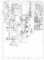
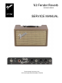
’63 Fender Reverb
REISSUE SERIES
SERVICE MANUAL
Fender Musical Instruments Corp.
7975 North Hayden Road Scottsdale, AZ 85258
’63 Fender Reverb
(This is the model name for warranty claims)
SERVICE MANUAL
JUNE 1994 REV A
TYPE PR 263
IMPORTANT NOTICE:
The information contained herein is CONFIDENTIAL and PROPRIETARY to Fender Musical Instruments Corp. It is
disclosed solely for use by qualified technicians for purposes of equipment maintenance and service. It is not to be
disclosed to others without the expressed permission of Fender Musical Instruments Co. All specifications subject to
change without notice.
For warranty repair service, only Fender specified part numbers are to be used. It is recommended they also be used
for post-warranty maintenance and repair.
Parts marked with an asterisk (*) indicate the required use of that specific part. This is necessary for RELIABILITY
and SAFETY requirements. DO NOT USE A SUBSTITUTE!
A coded naming convention is used in the description of certain parts. The codes and what they mean are as follows:
CAPACITOR CODES
HARDWARE CODES
CAP AE
CAP CA
CAP CD
CAP MPF
CAP MY
CAP PFF
BLX
CR
HWH
M
NI
OHP
PB
PHP
PHPS
SMA
SMB
SS
TF
ZI
=
=
=
=
=
=
Aluminum Electrolytic
Ceramic Axial
Ceramic Disk
Metalized Polyester Film
Mylar
Polyester Film/Foil
RESISTOR CODES
RES CC
RES CF
RES FP
RES MF
RES WW
=
=
=
=
=
Carbon Comp
Carbon Film
Flame Proof
Metal Film
Wire Wound
=
=
=
=
=
=
=
=
=
=
=
=
=
=
Black Oxide
Chrome Plated
Hex Washer Head
Machine Screw
Nickel Plated
Oval Head Phillips
Particle Board
Pan Head Phillips
Pan Head Phillips Sems
Sheet Metal "A" Point
Sheet Metal "B" Point
Stainless Steel
Thread Forming
Zinc Plated
’63 Fender Reverb
THEORY OF OPERATION
The input jack contains a Tip Shunt switch contact which will ground the input when the plug is removed.
The input impedance consists of R1R11 and R12 in parallel, and equals approx. 500k ohm.
The first stage (V1A) provides a voltage gain of 38.8 (V out/V in = 1.94V/50mV =38.8). Bypass capacitor C2
increases the AC gain, and also reduces hum. The voltage divider R2 and R3 reduce the voltage so the overall gain
is about 3. The signal then feeds the Dwell control, which determines the amount of signal sent to the reverb drive
circuit.
V1B provides a voltage gain of 20. C3 and R9 make up a single pole filter which provides 6db per octave of low
frequency roll off at 300Hz. Excessive low frequencies can make the reverb sound unnatural and boomy.
V2 is a 6V6GT power tube which supplies voltage and current gain to drive the reverb transformer. Due to the lack of
availability, the original 6K6 power tube was replaced with a modern 6V6. CR7 (56V Zener) protects C4 from
exploding if V2 develops an internal short. This is necessary to conform to modern day NEMKO safety requirements.
The footswitch turns the reverb on and off by grounding the input to the reverb recovery circuit. R13 provides a
ground reference (or bias) for the input of V3A. This prevents instability in V3A if the reverb recovery cable is
disconnected from the reverb pan. V3A senses the reverb return signal and amplifies it with a gain of about 37.
The Tone control (R17) attenuates the high frequencies above 3kHz, through C9. C10 provides a slight bass roll off
which is affected by the position of the Mix control in relation to the input impedance of the guitar amplifier.
V3B is a cathode follower, unity gain buffer amplifier for the dry signal.
C11 is a non-polarized, metalized polyester film capacitor, which is located across the high voltage transformer
secondary, suppresses EMI frequencies from 20kHz to 30mHz. This is necessary to conform to modern day NEMKO
safety requirements.
The pot mounting brackets are all connected together via traces on the circuit board. The trace connects to the star
audio ground through R22, R22 places 15 ohms of resistance between audio ground and the pot mounting brackets.
This is done for two reasons. Fist, with the circuit board installed, the pot brackets are physically connected to
chassis/earth ground. R22 isolates audio ground from earth ground through the pot brackets. This eliminates internal
ground loops. Secondly, when the circuit board is removed for repair and testing, R22 provides a ground reference
(15 ohms) for the pot brackets. R23 places 15 ohms of resistance between audio ground and chassis/earth ground.
This minimizes hum by eliminating ground loops internally and externally when connection with other units. R22 and
R23 are Flame Proof/Fusible resistors. If excessive current flows through theses resistors, they will not burn, they will
simply open.
CR5 & 6 (across R23) provide an important safety feature. IF the guitar amp chassis becomes electrified, current will
flow through the coax cable to the power supply ground of the Fender Reverb unit. The current will seek earth ground
through R23. When R23 opens, the earth ground connection is broken. This will electrify the reverb unit’s ground and
thus the guitar (ouch!). CR5 & 6 provide an alternate path to earth ground if R23 opens.
’63 Fender Reverb
PARTS LIST
NOTE: SHADED ITEMS ARE FOR REFERENCE ONLY
QTY
2
2
2
1
1
1
2
1
2
1
1
1
2
4
4
1
14
2
2
1
1
2
2
2
4
1
4
1
2
2
1
1
PART #
PRINTED CIRCUIT BOARD ASSEMBLY
DESCRIPTION
REFERENCE DESIGNATION
037325
024819
009512
041589
038695
020917
024823
024845
024854
024855
026202
047608
036962
026730
029045
047206
025802
037117
020888
047596
047595
031901
033205*
026368
024969
024981
025116
025059
025069
025075
027349
036921
CABLE FLAT 6 CKT 2 INCH
CAP AE AX 22uf 500V
20%
CAP AE AX 22uF 25V 20%
CAP AE AX 47uF 500V 20%
CAP AE
220uF 16V 20%
CAP CD 250PF 1000V 10%
CAP MPF RDL .01uF 400V 10%
CAP MPF RDL .017uF 400V 10%
CAP MPF RDL .1uF 400V 10%
CAP MPF RDL .1uF 630V 10%
CAP PFF .0022uF 600V
CONTROL SNAPIN 50K B TAPER
CONTROL SNAPIN 250K B TAPER
DIODE 1N4006/1N5062 800PRV 1A
DIODE 6A 400V 6A4 LEAD FORMED
DIODE ZEN 1N5370V 56V 5W 5%
FSTN TAB MALE.250X.032 PCB MT
JACK PCB MONO CLOSED CKT
JUMPER WIRE 22GA.5X.175
PCB ASSY 63 TUBE REVERB
PCB FAB 63 TUBE REVERB
PIN MALE PCB .093 DOA
RES MF FUSE 1/4W 5% 15OHM
RES CF 1/2W 5% 100OHM
RES CF 1/4W 5% 1.5K
RES CF 1/4W 5% 10K
RES CF 1/2W 5% 100K
RES CF 1/4W 5% 220K
RES CF 1/4W 5% 1M
RES CF 1/4W 5% 2.2M
RES FILM 1W 5% 10K
RES FILM 2W 5% 1K
C12,13
C2,4
C14
C7
C10
C1,9
C5
C5
C6,8
C3
R17
(TONE CONTROL)
R5,18
(DWELL, MIX CONTROL)
CR1,2,3,4
CR5,6
CR7
CP1-14
J1,2
(STUFFED)
(RAW PCB)
SP1,2
R22,23
R19,20
R4,6,8,15
R2
R3,7,14,16
R9
R1,13
R11,12
R21
R10
CHASSIS ASSEMBLY
QTY
2
1
1
1
1
1
1
1
1
1
1
1
1
1
1
2
PART #
DESCRIPTION
018022
026038
010401
026541
033331
047597
022707
047988
032219
036702
036703
010036
013109
021741
021956
033329
BUSHING SNAP 5/16X17/32 BLK
BUSHING SR .625X.062X37/64 BLK
BUSHING SR .625X.125X37/64 WHT
CABLE ASSY PWR W/.250 TAB 120V
CABLE ASSY PWR 220/240V
CHASSIS 63 REVERB
CHIKE FILTER
CHS ASSY BROWN 120V 63 TUBE RB
COLLAR-PILOT LIGHT
FUSE HOLDER 3AG FINGER GRIP
FUSE HOLDER 5mm FINGER GRIP
FUSE TD 1-1/4X1/4 250V 0.5A
FUSE TD 20mmX5mm 250V 250mAT
HOLDER IDAL LITE ASSY PILOT
JACK PHONE OPEN CIRCUIT 11
JACK PHONO 2 CND PNL MT
REFERENCE DESIGNATION
(@ POWER CABLE 100/120V)
(@ POWER CABLE 230V)
(POWER CABLE 100/120V ONLY)
(POWER CABLE 230V)
(RAW CHASSIS)
L1
(THROUGH FRONT PANEL)
XF1
(100V/120V ONLY)
XF1
(230V EXPORT)
F1
(100V/120V ONLY)
F1
(220V/230V/240V ONLY)
(PILOT LAMP SOCKET)
J3
(FOOTSWITCH JACK)
J4,5
(REVERB JACKS)
’63 Fender Reverb
QTY
1
3
3
1
2
1
1
1
12
2
12
6
1
1
1
1
1
2
1
2
2
2
1
3
3
1
1
1
PART #
025718
036678
041263
031625
022004
047598
047599
021642
031184
026553
038900
031073
036570
023531
023564
013341
020424
036598
023580
023606
047950
047949
9904300920
027520
026401
047609
047610
04605
CHASSIS ASSEMBLY (CONT)
DESCRIPTION
REFERENCE DESIGNATION
JEWEL #20 PILOT LITE
KNOB VINTAGE DARK BROWN
KNOB VINTAGE CREAM
NUT HOLDER PILOT LIGHT 1/16-27
NUT KEPS #8-32 ZINC
PANEL FRONT 63 TUBE RVRB BROWN
PANEL FRONT 63 TUBE RVRB BLACK
PILOT LIGHT #T47
SCRW M 6-32X1/4 PHPSBLX
SCRW M 8-32X3/8 PPHP BLX
SCRW TF 6-32X3/8 PHP ZI
STANDOFF 6-32X3/8 RND AL
SWITCH TOGGLE DPST W/ NUTS
TUBE 12AT7
TUBE 6V6GTA STR391A
TUBE 7025/12AX7
TUBE RING UNIVERSAL (277H-2)
TUBE SHIELD
TUBE SOCKET 8 PIN
TUBE SOCKET 9 PIN
WASHER FIBER FLAT RCA
WASHER FIBER SHOULDER RCA
WASHER FLAT .482X.709 NI
WSHR FLAT .380X.630 FIBER
WSHR SHLDR FIB 3/8X5/8
XFMR POWER 120V DOMESTIC
XFMR POWER EXPORT
XFMR REVERB DRIVER OUTPUT
(RED)
(BROWN CABINET)
(BLACK, BLOND CABINET)
(POWER XFMR MOUNT)
(BROWN, BLOND CABINET)
(BLACK CABINET)
(PCB MOUNT)
(POWER XFMR MOUNT)
(PCB MOUNT)
S1
(POWER SWITCH)
V1
V2
V3
(@V2)
(@V1,3)
XV2
SV1,3
@J4,5
(@J4,5)
(@ POWER SWITCH)
(@J1,2,3)
(@J1,2,3)
T1
(120V ONLY)
T1
(100/110/120/220/230/240V)
T2
CABINET ASSEMBLY
QTY
1
1
1
1
1
1
1
1
1
1
1
1
1
2
1
1
4
2
1
1
1
4
2
2
2
8
4
3
PART #
DESCRIPTION
047606
047591
037003
047590
047625
047638
047640
047816
047639
047637
047627
037790
036129
036478
036795
023192
022004
025819
047603
048462
036650
047604
026419
036619
022244
029828
037952
037210
037985
BRACKET “L” REVERB HOLD DOWN
CAB ASSY 63 REVERB BROWN/TAN
CAB ASSY 63 REVERB BLOND/OXBLD
CAB ASSY 63 REVERB BLACK/SILVER
BACK ASSY 63 REVERB BLACK
BACK ASSY 63 REVERB BLOND
BACK ASSY 63 REVERB BROWN
CABLE REVERB 350MM
GRILLE ASSY 63 REVERB TAN
GRILLE ASSY 63 REVERB OXBLOOD
GRILLE ASSY 63 REVERB SILVER
HANDLE 9.25” BLACK RIBBED
HANDLE 9” LEATHER BROWN
HANDLE CAP NI
NAMEPLATE 62 FENDER
NAMEPLATE FENDER 65 TWIN
NUT KEPS #8-32 ZINC
NUT KEPS 10-32 ZINC
PANEL REAR 63 REVERB BRN TEXT
PANEL REAR 63 REVERB BLK TEXXXT
PIN ESCUTCHEON #16X3/8 NI
REVERB UNIT 8 OHM 4AB3C1C VERT
SCRW 8/32X1 PHP STL NI
SCRW M 10-32X1-1/2 THP NI
SCRW M 8-32/X-1/2 FHP BLK
SCRW PB 8X3/4 PHP ZI
SCRW SMA #6X1 OHP NI
SCRW MSMA 2X3/8 OHP NI
SCRW SMA 2X3//8 PHP BLX
REFERENCE DESIGNATION
(BROWN CABINET, TAN GRILE)
(BLOND CABINET, OXBLOOD GRILLE)
BLACK CABINET, SILVER GRILLE
(BACKBOARD)
(BACKBOARD)
(BACKBOARD)
(USED ON BROWN CABINET)
(USED ON BLOND CABINET)
(USED ON BLACK CABINET)
(USED ON BLACK CABINET)
(ON BROWN & BLOND CAB)
(@ HANDLE, BLACK CABINET)
(BROWN, BLOND CABINET)
(BLACK CABINET)
(@GRILLE, REVERB MOUNT)
(CHASSIS MOUNT)
(@ BROWN, BLOND CABINET)
(BLACK CABINET)
(PANEL REAR, MOUNT)
(LEATHER HANDLE MOUNT)
(CHASSIS MOUNT)
(@ GRILLE, REVERB MOUNT)
(@ HOLD DOWN BRACKET)
(GRILLE/BACK MOUNT)
(62 VINTAGE LOGO MOUNT)
(65 LOGO MOUNT)
’63 Fender Reverb
QTY
4
4
8
4
QTY
1
1
1
1
1
12ft
PART #
CABINET ASSEMBLY (CONT)
DESCRIPTION
REFERENCE DESIGNATION
047784
047607
037215
026459
SPRING ANCHOR
SPRING EXTENSION
WSHR C’SNK #6 NI
WSHR FLAT 6X3/8 ZI
PART #
DESCRIPTION
048458
021691
022657
028915
024042
023861
FOOTSWITCH 1BTN VINTAGE SHIELD
BUSHIUNG SR .500X.100X7/16 BLK
COVER CUP SINGLE FT SW.ASSY
PLUG PHONE RTANG SHIELDED
SWITCH SPST PUSH BUTTON
WIRE BLACK STRANDED 2 COND PLA
PART #
DESCRIPTION
REFERENCE DESIGNATION
047980
047593
MANUAL OWNERS 63 FENDER REVERB
SCHEM REDUC 63 FENDER REVERB
(WITH SERVICE DIAGRAM)
(SPRING OVER SCREW)
(FROM ANCHOR TO PAN)
(GRILLE/BACK MOUNT)
FOOTSWITCH ASSEMBLY
REFERENCE DESIGNATION
(COMPLETE FOOTSWITCH)
MISCELLANEOUS
QTY
1
1