1
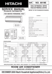
NO. 0164E
PM
RAS-25CNH11
RAC-25CNH11
SERVICE MANUAL
TECHNICAL INFORMATION
REFER TO THE FOUNDATION MANUAL
FOR SERVICE PERSONNEL ONLY
CONTENTS
SPECIFICATIONS --------------------------------------------------------------4
SAFETY PRECAUTION ------------------------------------------------------6
HOW TO USE -------------------------------------------------------------------8
CONSTRUCTION AND DIMENSIONAL DIAGRAM ---------------- 29
MAIN PARTS COMPONENT --------------------------------------------- 30
RAS-25CNH11
WIRING DIAGRAM ----------------------------------------------------------- 33
CIRCUIT DIAGRAM ---------------------------------------------------------- 35
BLOCK DIAGRAM ------------------------------------------------------------ 39
BASIC MODE ------------------------------------------------------------------ 41
AUTO SWING FUNCTION------------------------------------------------- 54
DESCRIPTION OF MAIN CIRCUIT OPERATION ------------------ 55
REFRIGERATING CYCLE DIAGRAM ---------------------------------- 86
SERVICE CALL Q & A ----------------------------------------------------- 87
RAC-25CNH11
TROUBLE SHOOTING ------------------------------------------------------ 91
PARTS LIST AND DIAGRAM------------------------------------------- 113
SPECIFICATIONS
WALL TYPE
TYPE
MODEL
INDOOR UNIT
OUTDOOR UNIT
RAS-25CNH11
RAC-25CNH11
POWER SOURCE
1ø 220V 50Hz
TOTAL INPUT
(W)
910 (190 ` 1,150) [COOL] / 1,250 (160 ` 1,350) [HEAT]
TOTAL AMPERES (RATED / MAX.)
(A)
4.20 ` 3.85 [COOL] / 5.75 ` 5.25 [HEAT]
(kW)
2.50 (0.90 ` 2.80)
(B.T.U./h)
8,870 (3,070 ` 9,550)
(kW)
3.60 (0.90 ` 4.00)
(B.T.U./h)
12,280 (3,070 ` 13,650)
COOLING CAPACITY
HEATING CAPACITY
DIMENSIONS
(mm)
NET WEIGHT
W
744
700
H
248
570
D
168
210
(kg)
5.5
29
SPECIFICATIONS AND PARTS ARE SUBJECT TO CHANGE FOR IMPROVEMENT
ROOM AIR CONDITIONER
INDOOR UNIT + OUTDOOR UNIT
JANUARY 2003
H.A.P.M.
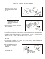
SAFETY DURING REPAIR WORK
1. In order to disassemble and repair
the unit in question, be sure to
disconnect the power cord plug
from the power outlet before starting
the work.
ct
nne
o
c
s
di
ust d plug .
m
I
or
t,
et
Firs ower c er outl
p
w
the the po
from
2. If it is necessary to replace any parts, they should be replaced with respective genuine parts for the unit, and
the replacement must be effected in correct manner according to the instructions in the Service Manual of
the unit.
If the contacts of electrical parts
are defective, replace the
electrical parts without trying to
repair them.
3. After completion of repairs, the initial state
should be restored.
4. Lead wires should be connected and laid as
in the initial state.
5. Modification of the unit by user himself should
absolutely be prohibited.
6. Tools and measuring instruments for use in repairs or inspection should be accurately calibrated in advance.
7. In installing the unit having been repaired, be careful to prevent the occurence of any accident such as
electrical shock, leak of current, or bodily injury due to the drop of any part.
8. To check the insulation of the unit, measure the insulation resistance between the power cord plug and
grounding terminal of the unit. The insulation resistance should be 1M
or more as measured by a 500V
DC megger.
9. The initial location of installation such as window, floor or the other should be checked for being and safe
enough to support the repaired unit again.
If it is found not so strong and safe, the unit should be installed at the initial location reinforced or at a new
location.
10. Any inflammable thing should never
be placed about the location of
installation.
11. Check the grounding to see whether
it is proper or not, and if it is found
improper, connect the grounding
terminal to the earth.
DANGER
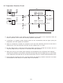
WORKING STANDARDS FOR PREVENTING BREAKAGE OF SEMICONDUCTORS
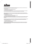
1. Scope
The standards provide for items to be generally observed in carrying and handling semiconductors in relative
manufacturers during maintenance and handling thereof. (They apply the same to handling of abnormal goods
such as rejected goods being returned).
2. Object parts
(1)
(2)
(3)
(4)
Micro computer
Integrated circuits (IC)
Field-effect transistors (FET)
P.C. boards or the like on which the parts mentioned in (1) and (2) of this paragraph are equipped.
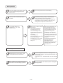
3. Items to be observed in handling
(1) Use a conductive container for carrying and storing of parts. (Even rejected goods should be handled in
the same way).
IC
A conductive polyvinyl bag
Conductive sponge
IC
Fig. 1. Conductive Container
(2) When any part is handled uncovered (in counting, packing and the like), the handling person must always
use himself as a body earth. (Make yourself a body earth by passing one M ohm earth resistance through
a ring or bracelet).
(3) Be careful not to touch the parts with your clothing when you hold a part even if a body earth is being
taken.
(4) Be sure to place a part on a metal plate with grounding.
(5) Be careful not to fail to turn off power when you repair the printed circuit board. At the same time, try
to repair the printed circuit board on a grounded metal plate.
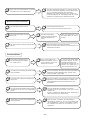
Body earth
(Elimik conductive band)
Clip for connection with a
grounding wire
1M
Fig. 2. Body Earth
– 1 –
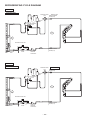
(6) Use a three wire type soldering iron including a grounding wire.
Metal plate (of aluminium, stainless steel, etc.)
Working
table
Resistor of 1 M
(1/2W)
Staple
Earth wire
Bare copper wire (for body earth)
Fig. 3. Grounding of the working table
Soldering iron
2
Grounding
wire
Screw stop at the screwed
part using a rag plate
Fig. 4. Grounding a soldering iron
Use a high insulation mode (100V, 10M
or higher) when ordinary iron is to be used.
(7) In checking circuits for maintenance, inspection or some others, be careful not to have the test probes of the
measuring instrument shortcircuit a load circuit or the like.
– 2 –
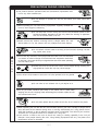
CAUTION
1.
In quiet operation or stopping the running, slight flowing noise of refrigerant in the refrigerating cycle is heard
occasionally, but this noise is not abnormal for the operation.
2.
When it thunders near by, it is recommend to stop the operation and to disconnect the power cord plug from
the power outlet for safety.
3.
If the room air conditioner is stopped by setting the temperature or mis-operation, and then re-started in a
moment, cooling operation does not start for 3 minutes, it is not abnormal and this is the result of the
operation of IC delay circuit. This IC delay circuit ensures that there is no danger of blowing fuse or
damaging parts even if operation is restarted accidentally.
4.
This room air conditioner should not be used at the cooling operation when the outside temperature is below
20°C.
5.
When the operation knob is set to “COOL” from another position, IC delay circuit functions and stops the
compressor for the first 3 minutes, which is not an abnormal phenomenon.
– 3 –
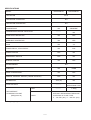
SPECIFICATIONS
RAS-25CNH11
MODEL
FAN MOTOR
RAC-25CNH11
20 W
FAN MOTOR CAPACITOR
NO
FAN MOTOR PROTECTOR
NO
COMPRESSOR
NO
GR20DR2F
----------
COMPRESSOR MOTOR CAPACITOR
NO
OVERLOAD PROTECTOR
NO
YES
OVERHEAT PROTECTOR
NO
YES
FUSE
NO
3A
POWER RELAY, STICK RELAY
NO
G4A
POWER SWITCH
YES
NO
TEMPORARY SWITCH
YES
NO
SERVICE SWITCH
NO
YES
TRANSFORMER
NO
VARISTOR
NO
416NR
NOISE SUPPRESSOR
NO
YES
REMOTE CONTROL SWITCH (LIQUID CRYSTAL)
YES
NO
THERMOSTAT
YES (IC)
NO
FUSE CAPACITY
----------
16A INRUSH
WITHSTAND TYPE
----------
❈ 690g
UNIT
REFRIGERANT
CHARGING VOLUME
(Refrigerant 22)
WITHOUT REFRIGERANT BECAUSE
COUPLING IS FLARE TYPE.
P - 105 VK1 (5m), P - 108 VK1 (8m)
PIPES
❈ 690g for piping set of 5~8m.
– 4 –
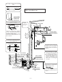
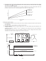
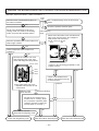
The Length of Indoor Unit Connecting
Cord
about
0.9m
about 1.6m
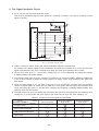
Figure showing the Installation of
Indoor and Outdoor Unit.
20
Cut away shaded
portion, and finish
the edge of the
opening so that
there is no burr.
Be sure to
completely
seal any gap
with putty.
Direction of Piping
above 50mm
above 100mm
There are 3 directions allowed,
namely, horizontally perpendicular to
the unit, vertically down from right,
horizontally out from right.
Don’t form the piping downward at the
left of the unit.
above 300mm
Connection
must not bend about 0.45m
Horizontally
perpendicular
to the unit
above 100mm
6 Used in horizontal piping
2,500mm or more
Dimension of Mounting Stand
of the outdoor unit
(unit : mm)
Maximum pipe length 8m
35
12
225
8
mounting stand
35
500
100
Plug
The indoor piping should be
insulated with the enclosed
insulation pipe. (If the insulator is
insufficient, please use commersial
products).
●
above 200mm
●
above 50mm when
installed on the
ceiling of balcony
❈ above 100mm
❈ give clearance
as wide as possible
The difference in height
between the indoor and outdoor
unit should be kept below 5m.
The connecting pipe, no matter
big or small, should all be
insulated with insulation pipe
and then wrapped with vinyl
tape. (The insulator will
deteriorate if it is not wrapped
with tape).
above 100mm
The connection of insulated drain
hose.
inner diameter ø 16mm
❈ above 300mm
above 200mm
– 5 –
Please use insulated drain hose
for the indoor piping (commercial
product).
SAFETY PRECAUTION
●
●
●
Please read the “Safety Precaution” carefully before operating the unit to ensure correct usage of the unit.
Pay special attention to signs of “ ! Warning” and “ ! Caution”. The “Warning” section contains matters which,
if not observed strictly, may cause death or serious injury. The “Caution” section contains matters which may
result in serious consequences if not observed properly. Please observe all instructions strictly to ensure safety.
The sign indicate the following meanings.
The sign in the figure indicates prohibition.
Make sure to connect earth line.
Indicates the instructions that must be followed.
●
Please keep this manual after reading.
PRECAUTIONS DURING INSTALLATION
!
●
Do not reconstruct the unit.
Water leakage, fault, short circuit or fire may occur if you reconstruct
the unit by yourself.
●
Please ask your sales agent or qualified technician for the installation
of your unit. Water leakage, short circuit or fire may occur if you install
the unit by yourself.
●
Please use earth line.
Do not place the earth line near water or gas pipes, lightning-conductor,
or the earth line of telephone. Improper installation of earth line may
cause electric shock.
●
A circuit breaker should be installed depending on the mounting site of
the unit. Without a circuit breaker, the danger of electric shock exists.
●
Do not install near location where there is flammable gas. The outdoor
unit may catch fire if flammable gas leaks around it.
●
Please ensure smooth flow of water when installing the drain hose.
WARNING
!
CAUTION
PRECAUTIONS DURING SHIFTING OR MAINTENANCE
!
W
A
R
N
I
N
G
●
Should abnormal situation arises (like burning smell), please stop operating the unit
and turn off the circuit breaker. Contact your agent. Fault, short circuit or fire may
occur if you continue to operate the unit under abnormal situation.
●
Please contact your agent for maintenance. Improper self maintenance may cause
electric shock and fire.
●
Please contact your agent if you need to remove and reinstall the unit. Electric
shock or fire may occur if you remove and reinstall the unit yourself improperly.
PRECAUTIONS DURING OPERATION
●
!
W
A
R
N
I
N
G
Avoid an extended period of direct air flow for your health.
●
●
Do not put objects like thin rods into the panel of blower and suction side
because the high-speed fan inside may cause danger.
Do not use any conductor as fuse wire, this could cause fatal accident.
●
During thunder storm, disconnect and turn off the circuit breaker.
– 6 –
PRECAUTIONS DURING OPERATION
●
The product shall be operated under the manufacturer specification and
not for any other intended use.
●
●
When operating the unit with burning equipments, regularly ventilate the
room to avoid oxygen insufficiency.
●
●
●
C
A
U
T
I
O
N
Please switch off the unit and turn off the circuit breaker during cleaning, the
high-speed fan inside the unit may cause danger.
Turn off the circuit breaker if the unit is not to be operated for a long period.
●
●
Do not splash or direct water to the body of the unit when cleaning it as this
may cause short circuit.
Do not use any aerosol or hair sprays near the indoor unit. This chemical
can adhere on heat exchanger fin and blocked the evaporation water flow
to drain pan. The water will drop on tangential fan and cause water splashing
out from indoor unit.
●
●
Do not direct the cool air coming out from the air-conditioner panel to face
household heating apparatus as this may affect the working of apparatus
such as the electric kettle, oven etc.
Please ensure that outdoor mounting frame is always stable, firm and
without defect. If not, the outdoor unit may collapse and cause danger.
●
!
Do not attempt to operate the unit with wet hands, this could cause fatal
accident.
Do not climb on the outdoor unit or put objects on it.
Do not put water container (like vase) on the indoor unit to avoid water
dripping into the unit. Dripping water will damage the insulator inside the unit
and causes short-circuit.
●
Do not place plants directly under the air flow as it is bad for the plants.
When operating the unit with the door and windows opened, (the room humidity is always above
80%) and with the air deflector facing down or moving automatically for a long period of time,
water will condense on the air deflector and drips down occasionally. This will wet your furniture.
Therefore, do not operate under such condition for a long time.
● If the amount of heat in the room is above the cooling or heating capability of the unit (for
example: more people entering the room, using heating equipments and etc.), the preset room
temperature cannot be achieved.
●
– 7 –
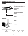
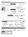
NAMES AND FUNCTIONS OF EACH PART
INDOOR UNIT
Air filter
To prevent dust from coming into the indoor unit.
(Refer page 25)
Indoor unit indicators
Light indicator showing the operating condition.
(Refer page 9)
Front panel (Air Inlet)
Horizontal deflector
(Air Outlet)
(Refer page 20)
●
Vertical deflector
Remote controller
Send out operation signal to the indoor unit. So as to
operate the whole unit.
(Refer page 10)
OUTDOOR UNIT
DRAIN PIPE
Condensed water drain to outside.
CONNECTING CORD
AIR INLET (BACK, LEFT SIDE)
AIR OUTLET
MODEL NAME AND DIMENSIONS
MODEL
WIDTH (mm)
HEIGHT (mm)
DEPTH (mm)
RAS-25CNH11
745
248
175
RAC-25CNH11
700
570
210
– 8 –
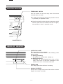
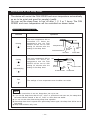
OPERATION INDICATOR
TEMPORARY SWITCH
Use this switch to start and stop when the remote
controller does not work.
●
By setting the temporary switch, the operation is done
in previously set operation mode.
●
When the operation is done using the temporary switch
after the power source is turned off and turn on again,
the operation is done in automatic mode.
POWER SWITCH
INDOOR UNIT INDICATORS
OPERATION LAMP
This lamp lights during operation.
The OPERATION LAMP flashes in the following cases
during heating.
(1) During preheating
For about 2–3 minutes after starting up.
(2) During defrosting
Defrosting will be performed about once an hour
when frost forms on the heat exchanger of the
outdoor unit, for 5–10 minutes each time.
TIMER LAMP
This lamp lights when the timer is working.
SIGNAL RECEIVER
There will be a beep sound when this receiver receives
signal from remote controller.
– 9 –
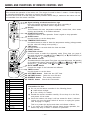
NAMES AND FUNCTIONS OF REMOTE CONTROL UNIT
REMOTE CONTROLLER
This controls the operation of the indoor unit. The range of control is about 7 meters. If indoor lighting
is controlled electronically, the range of control may be shorter.
This unit can be fixed on a wall using the fixture provided. Before fixing it, make sure the indoor unit can
be controlled from the remote controller.
● Signal emitting window/transmission sign
˚CH
●
●
●
●
●
●
●
˚CH
●
RESET
●
●
●
●
●
AUTO
●
Point this window toward the indoor unit when controlling it.
The transmission sign blinks when a signal is sent.
Display
This indicates the room temperature selected, current time, timer status,
function and intensity of circulation selected.
START/STOP button
Press this button to start operation. Press it again to stop operation.
SLEEP button
Use this button to set the sleep timer.
TEMPERATURE buttons
Use these buttons to raise or lower the temperature setting. (Keep pressed,
and the value will change more quickly.)
TIME button
Use this button to set and check the time and date.
RESET buttons
FUNCTION selector
Use this button to select the operating mode. Every time you press it,
the mode will change from
(AUTO) to
(HEAT) to
(DEHUMIDIFY) to
(COOL) and to
(FAN) cyclically.
FAN SPEED selector
This determines the fan speed. Every time you press this button, the intensity
of circulation will change from (AUTO) to (HI) to (MED) to (LOW)
(during the
(FAN) mode, from
HI to
MED to
LOW).
AUTO SWING button
Controls the angle of the horizontal air deflector.
TIMER control
Use this button to set the timer.
OFF-TIMER button Select the turn OFF time.
ON-TIMER button Select the turn ON time.
RESERVE button Time setting reservation.
CANCEL button Cancel time reservation.
HEAT
DEHUMIDIFY
COOL
FAN
FAN SPEED
LOW
MED
HI
SLEEPING
STOP (CANCEL)
START (RESERVE)
START/STOP
TIME
TIMER SET
TIMER SELECTOR
ON TIMER
OFF TIMER
AUTO SWING
Precautions for Use
● Do not put the remote controller in the following places.
● Under direct sunlight.
● In the vicinity of a heater.
● Handle the remote controller carefully. Do not drop it on the floor,
and protect it from water.
● Once the outdoor unit stops, it will not restart for about 3 minutes
(unless you turn the power switch off and on or unplug the power
cord and plug it in again).
This is to protect the device and does not indicate a failure.
● If you press the FUNCTION selector button during operation, the
device may stop for about 3 minutes for protection.
– 10 –
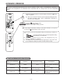
AUTOMATIC OPERATION
The device will automatically determine the mode of operation, HEAT, COOL or DEHUMIDIFY depending on
the initial room temperature. The selected mode of operation will not change when the room temperature
varies.
Press the FUNCTION selector so that the display indicates the
mode of operation.
1
●
START
STOP
RESET
(AUTO)
When AUTO has been selected, the device will automatically determine
the mode of operation, HEAT, COOL or DEHUMIDIFY depending on
the initial room temperature.
Press the
(START/STOP) button.
Operation starts with a beep.
Press the button again to stop operation.
■ As the settings are stored in memory in the remote controller, you only have
to press the
(START/STOP) button next time.
You can raise or lower the temperature setting as necessary by maximum of
3°C.
Press the temperature button and the temperature setting
will change by 1°C each time.
°C
●
●
The preset temperature and the actual room temperature may vary
somewhat depending on conditions.
The display does not indicate the preset temperature in the AUTO mode.
If you change the setting, the indoor unit will produce a beep.
■ Condition of Automatic Operation
Initial room temperature
(approx.)
23~27°C
Under 23°C
- - -
Over 27°C
Function
Temperature setting
FAN SPEED
COOL
27°C
HI at start, MED or LOW
after the preset temperature
is reached
DEHUMIDIFY
Slightly lower than the
room temperature
LOW
HEAT
23°C
HI at start, MED or LOW
after the preset temperature
is reached
– 11 –
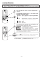
HEATING OPERATION
●
Use the device for heating when the outdoor temperature is under 21°C.
When it is too warm (over 21°C), the heating function may not work in order to protect the device.
˚C
1
2
RESET
Press the FUNCTION selector so that the display indicates
(HEAT).
Set the desired FAN SPEED with the (FAN SPEED) button
(the display indicates the setting).
(AUTO): The fan speed is HI at first and varies to MED
automatically when the preset temperature has
been reached.
(HI)
: Economical as the room will become warm
quickly.
But you may feel a chill at the beginning.
(MED) : Quiet.
(LOW) : More quiet.
Set the desired room temperature with the TEMPERATURE
buttons (the display indicates the setting).
3
˚C
The range of 18-22°C is recommended as the
room temperature for heating.
If the temperature setting is 20°C, the room
temperature will be controlled at around 20°C.
The temperature setting and the actual room temperature may
vary somewhat depending on conditions.
(START/STOP) button. Heating operation starts
START Press the
STOP with a beep. Press the button again to stop operation.
■ As the settings are stored in memory in the remote controller, you only
have to press the
(START/STOP) button next time.
– 12 –
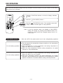
DEHUMIDIFYING OPERATION
Use the device for dehumidifying when the room temperature is over 16°C.
When it is under 15°C, the dehumidifying function will not work.
˚C
START Press the
(START/STOP) button. Dehumidifying operation
starts
with
a
beep.
Press the button again to stop operation.
STOP
1
RESET
Press the FUNCTION selector so that the display indicates
(DEHUMIDIFY).
The FAN SPEED is set at LOW automatically.
The FAN SPEED button does not work.
Set the desired room temperature with the TEMPERATURE
button (the display indicates the setting).
2
The range of 20-26˚C is recommended as the
room temperature for dehumidifying.
■ As the settings are stored in memory in the remote controller, you only
have to press the
(START/STOP) button next time.
■ Dehumidifying Function
When the room temperature is higher than the temperature setting: The device will dehumidify the room,
reducing the room temperature to the preset level.
When the room temperature is lower than the temperature setting: Dehumidifying will be performed at
the temperature setting slightly lower than the current room temperature, regardless of the temperature
setting. The function will stop (the indoor unit will stop emitting air) as soon as the room temperature
becomes lower than the setting temperature.
– 13 –
COOLING OPERATION
Use the device for cooling when the outdoor temperature is 22-42°C.
If in doors humidity is very high (80%), some dew may form on the air outlet grille of the indoor unit.
˚C
1
Press the FUNCTION selector so that the display indicates
(COOL).
Set the desired FAN SPEED with the
(the display indicates the setting).
RESET
2
(FAN SPEED) button
(AUTO): The FAN SPEED is HI at first and varies to
MED automatically when the preset temperature
has been reached.
(HI)
: Economical as the room will become cool
quickly.
(MED) : Quiet.
(LOW) : More quiet.
˚C
(START/STOP) button. Cooling operation starts
Press the
with
a
beep.
Press the button again to stop operation. The
START
STOP cooling function does not start if the temperature setting is
higher than the current room temperature (even though the
(OPERATION) lamp lights). The cooling function will start as
soon as you set the temperature below the current room
temperature.
3
Set the desired room temperature with the TEMPERATURE
button (the display indicates the setting).
The range of 25-28°C is recommended as the
room temperature for cooling.
If the temperature setting is 27°C, the room
temperature will be controlled at around 27°C.
The temperature setting and the actual room temperature may
vary some how depending on conditions.
■ As the settings are stored in memory in the remote controller, you
only have to press the
– 14 –
(START/STOP) button next time.
FAN OPERATION
You can use the device simply as an air circulator. Use this function to dry the interior of the indoor
unit at the end of summer.
1
2
RESET
START
STOP
Press the FUNCTION selector so that the display indicates
(FAN).
Press the
(FAN SPEED) button.*
Press the
(START/STOP) button. Fan operation starts with
a beep. Press the button again to stop operation.
* Note • In the fan operation mode, only display of FAN SPEED
setting will change by pressing FAN SPEED button; the
actual fan speed cannot be changed directly from HI to
LOW mode.
FAN SPEED (AUTO)
..... When the AUTO fan speed mode is set in the cooling/heating operation:
●
For the heating operation
●
●
●
For the cooling operation
●
The fan speed will automatically change according to the temperature
of discharged air.
When the difference of room temperature and setting temperature is
large, fan starts to run at HI speed.
When the room temperature reaches setting temperature, fan speed
changes to LOW automatically.
When the difference of room temperature and setting temperature is
large, fan starts to run at HI speed.
After room temperature reaches the preset temperature, the cooling
operation, which changes the fan speed and room temperature to obtain
optimum conditions for natural healthful cooling will be performed.
– 15 –
HOW TO SET THE TIMER
1 Set the current month and
Time, Day, Month
TIME, DAY,
MONTH
(current time,
day, month)
day with the TIMER control
button.
After you change the
batteries;
M
D
M
D
OFF TIMER
RESET
ON TIMER
1
OFF-Timer
Press the
(OFF-TIMER)
button. The
(OFF) mark blinks
on the display.
RESERVE
CANCEL
Start
AM
STOP
You can set the device to turn off
at the present time.
ON-Timer
Stop
●
Start
The device will turn on
at the designated times.
1
Press the
(ON-TIMER)
button the
(ON) mark blinks
on the display.
AM
1 Press the
ON/OFF-Timer
Start
Stop
button so that the
mark blinks.
● The device will turn on (off) and off
(on) at the designated times.
● The switching occurs first at the
preset time that comes earlier.
● The arrow mark appearing on the
display indicates the sequence of
switching operations.
(ON-OFF)
(OFF)
2
Set the turn-off time
with the TIMER control
button.
Press the
(RESERVE)
button.
3
Press the
(ONTIMER) button so that the
(OFF) mark lights and
the (ON) mark blinks.
PM
PM
PM
AM
How to Cancel Reservation
Point the signal window of the remote controller toward the indoor unit, and press the
(CANCEL)
button.
The (RESERVED) sign goes out with a beep and the (TIMER) lamp turns off on the indoor unit.
NOTE
You can set only one of the OFF-timer,
ON-timer and ON/OFF-timer.
– 16 –
3 Set the current time with the 4 Press the
2 Press the
(TIME) button again.
The time indication starts lighting
instead of flashing.
TIMER control button.
(TIME) button.
● The time indication will disappear
automatically in 10 second.
PM
AM
PM
● To check the current time setting,
PM
press the
The setting of the current time is
now complete.
Example: The current time is 1:30 p.m.
2
Set the turn-off time with the
TIMER control button.
PM
(TIME) button twice.
3 Point the signal window of the remote controller toward the indoor unit, and
press the (RESERVE) button.
The
(OFF) mark starts lighting instead of flashing and the sign
(RESERVED)
lights. A beep occurs and the
(TIMER) lamp lights on the indoor unit.
PM
Example: The device will turn off at 11:00p.m.
The setting of turn-off time is now complete.
2 Set the turn-on time with the
3 Point the signal window of the remote controller toward the indoor unit, and
TIMER control button.
press the (RESERVE) button.
The (ON) mark starts lighting instead of flashing and the
(RESERVED) sign
lights. A beep occurs and the
(TIMER) lamp lights on the indoor unit.
AM
4
Set the turn-on time with the
TIMER control button.
AM
Example:
The device will automatically turn on earlier so that the preset
temperature can be reached at 7:00 a.m.
The setting of the turn-on time is now complete.
5 Point the signal window of the remote controller toward the indoor unit, and
press the (RESERVE) button.
The (ON) mark starts lighting instead of flashing and the
(RESERVED) sign
lights. A beep occurs and the
(TIMER) lamp lights on the indoor unit.
PM
PM
AM
AM
Example:
The device will turn off at 10:30 p.m. and then automatically
turn on earlier so that the preset temperature can be reached
at 7:00 a.m.
The settings of the turn-on/off times are now complete.
●
The timer may be used in three ways: off-timer, on-timer, and ON/OFF (OFF/ON)-timer. Set
the current time at first because it serves as a reference.
●
As the time settings are stored in memory in the remote controller, you only have to press
the
(RESERVE) button in order to use the same settings next time.
– 17 –
HOW TO SET THE SLEEP TIMER
Set the current time at first if it is not set before (see the pages for setting
the current time). Press the
(SLEEP) button, and the display changes as
shown below.
Mode
Indication
41
Sleep timer
H
SLEEP
hour
42
hours 4 3 hours
Sleep timer off 1
47
hours
Sleep Timer: The device will continue working for the designated
number of hours and then turn off.
Point the signal window of the remote controller toward the indoor
unit, and press the SLEEP button.
The timer information will be displayed on the remote controller.
The TIMER lamp lights with a beep from the indoor unit. When the
sleep timer has been set, the display indicates the turn-off time.
Example: If you set 3 hours sleep
time at 11:38 p.m., the turn-off
time is 2:38 a.m.
H
Sleep
timer
Start
The device will be turned off by the sleep
timer and turned on by on-timer.
1 Set the ON-timer.
2 Press the (SLEEP) button and set the sleep timer.
AM
H
AM
For heating:
In this case, the device will turn off
in 2 hours (at 1:38 a.m.) and turn
on early so that the preset
temperature will be almost reached
at 6:00 next morning.
How to Cancel Reservation
Point the signal window of the remote controller toward the indoor unit, and press the
(CANCEL)
button.
The (RESERVED) sign goes out with a beep and the
(TIMER) lamp turns off on the indoor unit.
– 18 –
Explanation of the sleep timer
The device will control the FAN SPEED and room temperature automatically
so as to be quiet and good for people’s health.
You can set the sleep timer to turn off after 1, 2, 3 or 7 hours. The FAN
SPEED and room temperature will be controlled as shown below.
Operation with the sleep timer
Function
Heating
“
”
Operation
The room temperature will be
controlled 5°C below the
temperature and the FAN
SPEED will be set to LOW
setting 30 minutes after the
setting of the sleep timer.
5°C
Sleep timer set
30 minutes later
1 hour later
Cooling
“
”
and
dehumidifying
“
The room temperature will be
controlled 2°C above the
temperature and the FAN
SPEED will be set to LOW
setting 30 minutes after the
setting of the sleep timer.
Fan
“
3 hours later
2°C
Sleep
timer set
6 hours
later
7 hours later
2 hours
later
30 minutes later
”
7 hours
later
2 hours
later
3 hours later
The settings of room temperature and circulation are varied.
”
NOTE
●
●
●
●
●
If date or current time is not set, sleep timer can not be set.
If you set the sleep timer after the off-, on/off- or off/on-timer has been set, the sleep timer
becomes effective instead of the off-, on/off- or off/on-timer set earlier.
You can not set other timer during sleep timer operation.
After sleep timer time is up and when press sleep button again, the sleep timer will be set as
last setting.
Sleep timer effective only once.
– 19 –
ADJUSTING THE AIR DEFLECTOR
1
Adjustment of the conditioned air in the upward and downward
directions.
The horizontal air deflector is automatically set to the proper
angle suitable for each operation. The deflector can be swung
up and down continuously and also set to the desired angle
using the “
(AUTO SWING)” button.
●
If the “
(AUTO SWING)” button is pressed once,
the horizontal air deflector swings up and down. If the
button is pressed again, the deflector stops in its current
position. Several seconds (about 6 seconds) may be
required before the deflector starts to move.
●
Use the horizontal air deflector within the adjusting range
shown on the right.
●
When the operation is stopped, the horizontal air deflector
moves and stops at the position where the air outlet
closes.
RESET
When cooling
dehumidifying
! CAUTION
●
2
When heating
In “Cooling” operation, do not keep the horizontal air
deflector swinging for a long time. Some dew may form
on the horizontal air deflector and some dew drops may
fall from it.
Adjustment of the conditioned air to the left and right.
Hold the vertical air deflector as shown in the figure and adjust
the conditioned air to the left and right.
– 20 –
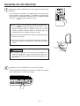
HOW TO EXCHANGE THE BATTERIES IN THE REMOTE CONTROLLER
1
Remove the cover as shown in the figure and take out the
old batteries.
Push and pull to the
direction of arrow
=
2
Install the new batteries.
The direction of the batteries should match the marks in the
case.
! CAUTION
1. Do not use new and old batteries, or different kinds of batteries
together.
2. Take out the batteries when you do not use the remote controller
for 2 or 3 months.
TEMPORARY SWITCH
Use this switch to start and stop when the
remote controller does not work.
●
By setting the temporary switch, the
operation is done in previously set operation
mode.
●
When the operation is done using the
temporary switch after the power source is
turned off and turn on again, the operation
is done in automatic mode.
TEMPORARY SWITCH
POWER SWITCH
– 21 –
THE IDEAL WAYS OF OPERATION
Suitable Room Temperature
Install curtain or blinds
! Warning
It is possible to
reduce heat
entering the
room through
windows.
Freezing temperature
is bad for health and a
waste of electric power.
Ventilation
Effective Usage Of Timer
At night, please use the “OFF or ON timer
operation mode”, together with your wake up
time in the morning. This will enable you to
enjoy a comfortable room temperature. Please
use the timer effectively.
! Caution
Do not close the room for a long period of
time. Occasionally open the door and windows
to allow the
entrance of
fresh air.
Do Not Forget To Clean The Air Filter
Dusty air filter will reduce the air volume and
the cooling efficiency. To prevent from wasting
electric energy, please clean the filter every 2
weeks.
Please Adjust Suitable Temperature
For Baby And Children
Please pay attention to the room temperature
and air flow direction when operating the unit
for baby, children and old folks who have
difficulty in movement.
– 22 –
FOR USER’S INFORMATION
The Air Conditioner And The Heat Source In The Room
! Caution
If the amount of heat in the room is above the cooling
capability of the air conditioner (for example: more
people entering the room, using heating equipments
and etc.), the preset room temperature cannot be
achieved.
Not Operating For A Long Time
When the indoor unit is not to be used for a long
period of time, please switch off the power from the
mains. If the power from mains remains “ON”, the
indoor unit still consumes about 8W in the operation
control circuit even if it is in “OFF” mode.
OFF
When Lightning Occurs
! Warning
To protect the whole unit during lightning, please
stop operating the unit and remove the plug from the
socket.
Interference From Electrical Products
! Caution
To avoid noise interference, please place the indoor
unit and its remote controller at least 1m away from
electrical products.
– 23 –
Inverter-type
fluorescent
lamp.
To prevent
interference,
place at least
1m away.
TV
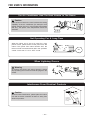
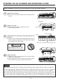
ATTACHING THE AIR CLEANSING AND DEODORIZING FILTERS
Before installation, be sure to stop the operation by using the remote controller.
1
Open the front panel.
● Pull up the front panel holding it at both sides by both
hands.
Front panel
2
Remove the filter.
● Push the filter upward to release the claws
and pull out the filter.
Front cover
Claws
Air filter
Claws (8 places)
Frame
3
Attaching the air cleansing and deodorizing filters to
the filter.
● Attach the air cleansing and deodorizing filters to the
frame by gently compress its both sides and release
after insertion into filter frame.
Make sure the “FRONT” is facing back side
! CAUTION
Do not bend the air cleansing
and deodorizing filter as it may
cause damage to the structure.
4
Attach the filter.
● Attach the filter by ensuring that the surface written
“FRONT” is facing front.
● After attaching the filter, push the front panel at three
arrow portions as shown in figure and close it.
NOTE
●
●
●
●
In case of removing the air cleansing and deodorizing filters, please follow the above procedures.
The cooling capacity is slightly weakened and the cooling speed becomes slower when the air cleansing
and deodorizing filters are used. So, set the fan speed to "HIGH" when using it in this condition.
Air cleansing and deodorizing filters are washable and reusable up to 20 times by using vacuum cleaner
or water rinse under running tap water. Type number for this air cleansing filter is <SPX-CFH5>.
Do not operate the air conditioner without filter. Dust may enter the air conditioner and fault may occur.
– 24 –
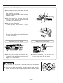
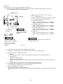
MAINTENANCE
!
CAUTION
Before the cleaning, stop operation and disconnect the power supply.
1.
AIR FILTER
Clean the air filter, as it removes dust inside the room. In case the air filter is full of dust, the air flow
will decrease and the cooling capacity will be reduced. Further, noise may occur. Be sure to clean the
filter following the procedure below.
REMOVING METHOD
PROCEDURE
1
2
Open the front panel and remove the filter
Gently lift and remove the air cleansing and
deodorizing filters from the air filter frame.
●
●
Vacuum dust from the air filter and air
cleansing and deodorizing filters using
vacuum cleaner. If there is too much dust,
rinse under running tap water and gently
brush it with soft bristle brush. Allow filters to
dry in shade.
Air cleansing and Air filter
deodorizing filter
INSTALLATION METHOD
3
●
●
Re-insert the air cleansing and deodorizing
filters to the filter frame. Set the filter with
"FRONT" mark facing front, and slot them
into the original state.
After attaching the filter, push the front panel
at three arrow portions as shown in figure
and close it.
NOTE:
●
Air cleansing and deodorizing filter should be cleaned every month or sooner if noticeable loading
occurs. When used overtime, it may loose its deodorizing function. For maximum performance,
it is recommended to replace it every 3-6 months depending on application requirements.
! CAUTION
●
Do not wash with hot water at more than 40°C. The filter may shrink.
●
When washing it, shake off moisture completely and dry it in the shade; do not expose it directly
to the sun. The filter may shrink.
●
Do not use detergent on the air cleansing and deodorizing filter as some detergent may deteriorate
the filter electrostatic performance.
– 25 –
2.
Washable Front Panel
●
Remove the front panel and wash with clean
water.
Wash it with a soft sponge.
After using neutral detergent, wash thoroughly
with clean water.
●
When front panel is not removed, wipe it with
a soft dry cloth. Wipe the remote controller
thoroughly with a soft dry cloth.
●
Wipe the water thoroughly.
If water remains at indicators or signal
receiver of indoor unit, it causes trouble.
Method of removing the front panel.
Be sure to hold the front panel with both hands
to detach and attach it.
Removing the Front Panel
Attaching the Front Panel
Arm
Projection
Hole
Flange
●
When the front panel is fully opened with
both hands, push the right arm to the inside
to release it, and while closing the front panel
slightly, put it out forward.
●
Move the projections of the left and right
arms into the Flanges in the unit and
securely insert them into the holes.
! CAUTION
●
●
Do not splash or direct water to the body of the unit when cleaning
it as this may cause short circuit.
Never use hot water (above 40°C), benzine, gasoline, acid, thinner or
a brush, because they will damage the plastic surface and the coating.
– 26 –
! CAUTION
Cleaning and maintenance must be carried out only by qualified service personal. Before cleaning,
stop operation and switch off the power supply.
3.
MAINTENANCE AT BEGINNING OF LONG OFF PERIOD
●
Run the unit by setting the operation mode to
(COOL), the temperature to 32°C and the fan speed
to HI for about half a day on a fine day, and dry the
whole of the unit.
●
Switch off the power plug.
Air
Blow
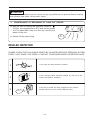
REGULAR INSPECTION
PLEASE CHECK THE FOLLOWING POINTS BY QUALIFIED SERVICE PERSONAL EITHER
EVERY HALF YEARLY OR YEARLY. CONTACT YOUR SALES AGENT OR SERVICE SHOP.
Is the earth line disconnected or broken?
1
2
Is the mounting frame seriously affected by rust and is the
outdoor unit tilted or unstable?
3
Is the plug of power line firmly plugged into the socket?
(Please ensure no loose contact between them).
Confirm
– 27 –
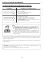
AFTER SALE SERVICE AND WARRANTY
WHEN ASKING FOR SERVICE, CHECK THE FOLLOWING POINTS.
CONDITION
CHECK THE FOLLOWING POINTS
●
When it does not operate
●
●
●
●
When it does not cool well
When it does not hot well
●
●
●
Is the fuse all right?
Is the voltage extremely high or low?
Is the circuit breaker “ON”?
Was the air filter cleaned?
Does sunlight fall directly on the outdoor unit?
Is the air flow of the outdoor unit obstructed?
Are the doors or windows opened, or is there any source of
heat in the room?
Is the set temperature suitable?
Notes
●
●
In quiet operation or stopping the operation, the following phenomena
may occassionally occur, but they are not abnormal for the operation.
(1) Slight flowing noise of refrigerant in the refrigerating cycle.
(2) Slight rubbing noise from the fan casing which is cooled and then
gradually warmed as operation stops.
The odor will possibly be emitted from the room air conditioner because
the various odor, emitted by smoke, foodstuffs, cosmetics and so on,
sticks to it. So the air filter and the evaporator regularly must be cleaned
to reduce the odor.
●
Please contact your sales agent immediately if the air conditioner still fails to operate normally after the above
inspections. Inform your agent of the model of your unit, production number, date of installation. Please also
inform him regarding the fault.
●
Power supply shall be connected at the rated voltage, otherwise the unit will be broken or could not reach the
specified capacity.
Please note:
On switching on the equipment, particularly when the room light is dimmed, a slight brightness fluctuation
may occur. This is of no consequence.
The conditions of the local Power Supply Companies are to be observed.
– 28 –
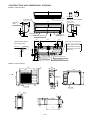
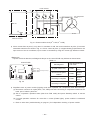
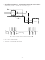
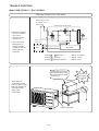
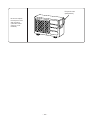
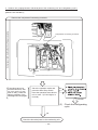
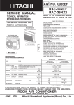
CONSTRUCTION AND DIMENSIONAL DIAGRAM
MODEL RAS-25CNH11
120
15
62
Top air suction grill
Air suction grill
1
Mounting
plate
Front cover
744
173
Wireless remote controller
147
VIEWED FROM BACK
(PIPE LEAD-OUT)
Horizontal air
deflector
P
Vertical air deflector
60
60
Drain cap connection part
When piping is drawn
horizontally, exchange
the drain hose for the
drain cap.
42.5
About 290
Drain Pan
Hole on the wall
for ø65 mm pipe
Line cord
Connecting cable
84
45
(147)
450
About 350
About 280
5
Discharge grill
45
23.5
5
59
59
248
6.5
Cabinet
Narrow pipe (ø6.35)
Wide pipe (ø9.52)
MODEL RAC-25CNH11
700
428
53
236
210
243
482
10
P
(18)
517
77
570
Handle
75
135
Air outlet
157
Air inlet
Handle
225
12
10
490
245
8
55
16
35
500
Viewed from P
– 29 –
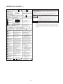
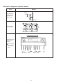
MAIN PARTS COMPONENT
THERMOSTAT
Thermostat Specifications
MODEL
RAS-25CNH11
THERMOSTAT MODEL
TEMPERATURE
°C (°F)
IC
INDICATION
16
ON
17.6 (63.7)
OFF
16.6 (61.8)
INDICATION
24
ON
25.6 (78.1)
OFF
24.6 (76.3)
INDICATION
32
ON
33.6 (92.5)
OFF
32.6 (90.7)
FAN MOTOR
Fan Motor Specifications
MODEL
RATED VOLTAGE
RAS-25CNH11
RAC-25CNH11
DC0 – 35V
DC230V
20W
20W
OUTPUT
WHITE
0`30V
RED
CONNECTION
YELLOW
5V
U
M
W
V
BLUE
RED
RESISTANCE VALUE
( )
YELLOW
20°C
(68°F)
–––––––
–––––––
75°C
(167°F)
–––––––
–––––––
– 30 –
COMPRESSOR MOTOR
Compressor Motor Specifications
MODEL
RAC-25CNH11
COMPRESSOR MODEL
GR20DR2F
PHASE
SINGLE
RATED VOLTAGE
AC 220 – 240 V
RATED FREQUENCY
50 Hz
POWER SOURCE FOR COMPRESSOR
Vcc max = 360V
POLE NUMBER
4
(U)
WHITE
CONNECTION
(V)
RESISTANCE VALUE
( )
YELLOW
20°C
(68°F)
2M = 3.21
75°C
(167°F)
2M = 3.90
(W)
RED
ORANGE
RED
WHITE
CAUTION
When the refrigerating cycle has been operated for a long time with the capillary tubes clogged or crushed
or with too little refrigerant, check the color of the refrigerating machine oil inside the compressor. If the
color has been changed conspicuously, replace the compressor.
– 31 –
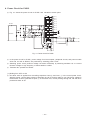
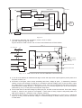
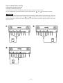
WIRING DIAGRAM
MODEL RAS-25CNH11 / RAC-25CNH11
Indoor unit
!
AC 220V
50HZ
T E R M I N A L B OA R D
!
L
N
BROWN
BLUE
4
3
2
1
BLUE
!
POWER SWITCH
+
FUSE (76 0 C)
CN9
H E AT E X C H A N G E R
T H E R M I S TO R
BLACK
RO O M
T H E R M I S TO R
The marked parts ! are very
important ones for safety.
CONNECTING
CABLE
BROWN
GREEN
YELLOW
GRAY
CAUTION
BLACK
A
(BLACK)
WHITE
B
(WHITE)
BROWN
C
D
(BROWN)
RED
TERMINAL
BOARD
!
GRAY
CN1
CN10
BLACK
LIGHT
RECEIVING
U N I T P. W. B.
(GREEN
+
Y E L L OW )
M
Outdoor unit
I N D O O R FA N M O T O R
!
TERMINAL BOARD
CN4
CN2
6
TEST
HA
CN6
CN7
123
1 2 3 4
CI C2 M1 M2
!
M
STEPPING MOTOR
A
BLACK
15A FUSE
!
AS1
CABLE
!
( B L AC K )
(WHITE)
(BROWN)
B
VS3
WHITE
D
DC FAN MOTOR
CONTROL
OUTDOOR
P. W. B.
WHITE
100 µ FX2
2A FUSE
FAN MOTOR
CONTROLLER
CN24
WHITE
CN2
RED
CN25
WHITE
OUTDOOR
FAN MOTOR
!
M
YELLOW
WHITE
BROWN
GRAY
!
OUTDOOR
TEMPERATURE
THERMISTOR
BLACK
BROWN
!
GRAY
GRAY
DEFROST
THERMISTOR
RED
GRAY
BLUE
DIODE
STACK !
GRAY
R805
!
R806
(50mQ)
YELLOW
CAPACITOR !
80 µ F
REACTOR
SMOOTHING
CAPACITOR
1000µF
DISCHARGE
RESISTANCE
PM1
( POWER MODULE) !
V
W
U
CN4
WHITE
BLUE
GRAY
RED
BLUE
GRAY
YELLOW
! R E V- VA LV E C O I L
BLUE
MAIN
P. W. B.
SWITCHING
POWER
SUPPLY
CN5
CN6
RED
GRAY
YELLOW
YELLOW
ZZZ
GREEN
WHITE
R807 RL1
RUSH CURRENT
PROTECTION !
RCI
~
DIODE
~
STACK
BALANCE
ZZZ
RED
CN26
CN16
~
ZZZ
BROWN
R805
RED
BROWN
9
! VS2
!
CN26 W H I T E
C
DIODE !
~ STACK
4 3
L801
NF-COIL
!
(RED)
(GREEN +
YELLOW)
C805
C806
YELLOW
POWER 4 3
RL2 RELAY
!
VS1
GREEN
CONNECTING
RL3 STICK
RELAY
! 3A FUSE
ZZZ
WIRELESS
R E M OT E C O N T RO L
M A I N P. W. B .
BLUE
YELLOW
RED
(RED)
RED
RED
YELLOW
WHITE
RED
YELLOW
WHITE
OVERHEAT
THERMISTOR
COMPRESSOR
MOTOR
!
– 33 –
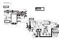
CIRCUIT DIAGRAM
MODEL RAS-25CNH11
– 35 –
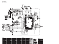
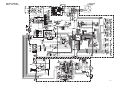
CIRCUIT DIAGRAM
MODEL RAC-25CNH11
– 37 –
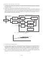
BLOCK DIAGRAM
MODEL
RAS-25CNH11/RAC-25CNH11
INDOOR UNIT
OUTDOOR UNIT
A
A
B
B
Power switch
FM
Magnetic relay
Outdoor DC fan motor
M
Power module
Power circuit
Inrush current
Protection circuit
DC compressor
motor
DC current signal
Rotor magnetic pole
position detection
circuit
Trip signal
synthesiz circuit
Wireless receive
circuit
LCD wireless
Buzzer circuit
Temporary switch
Indoor micro computer (AX-7J03)
Room temperature
thermistor
Heat exchanger
temperature thermistor
Overload control
circuit
Indicating lamp
Operation.
Timer.
Dehumidifying.
Voltage amplification
circuit
Over heat thermistor
M
Auto sweep motor for
Air deflector
Defrost thermistor
Outdoor micro computer (8E21)
Peak current cut off
circuit
C
C
D
D
Indoor / Outdoor
interface circuit
DC fan motor drive
circuit
Initial setting circuit
Lower arm
drive circuit
Self-diagnosis circuit
Outdoor temperature thermistor
Indoor / Outdoor
interface circuit
Peak current
cut off
Upper arm
drive circuit
Relay drive circuit
DC35V
Reset circuit
Reversing valve coil
Micro computer clock
circuit
FM
Indoor fan motor
Power circuit
(Indoor unit)
Clock circuit
Power circuit
(P.W.B.)
Reset circuit
(Watch dag)
– 39 –
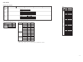
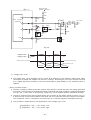
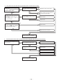
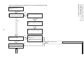
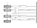
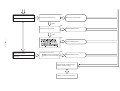
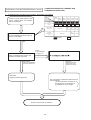
BASIC MODE
MODEL RAS-25CNH11
Operation mode
Fan
Cooling
Heating
Auto
Table 1
Model
Data
Basic
operation of
Start/Stop
switch
Start
Start / stop switch
Operation lamp
Stop
Start
Stop
Source
file name
Start / stop switch
Reserve switch
Cancel switch
Operation lamp
Timer lamp
OFF-timer
Timer memory
(OFF — timer in the stop mode)
(Reserved time change)
(Reserved time change)
Table 3 Room temp. shift value
Operation mode
Heating
Cooling,
dehumidifying
Normal
Shift value
(ON — timer in the operation mode)
Table 2 Room temp. shift value
Operation mode Fan speed tap Label name Voltage set
value
SHIFTW
Super Lo
AFWSS
SHIFTC
Lo
AFWS
16.6V
Cool Rhythm
SFTRZM
Overload
AFWKAF
19.1V
Heating
Med
AFWL
19.1V
Hi
AFWH
27.7V
Super Hi
AFWHH
27.7V
Lo
AFCS
16.0V
Med
AFCL
18.7V
Cooling
Dehumidifying
Hi
AFCH
20.9V
Super Hi
AFCHH
20.9V
Lo
AFDS
16.0V
Med
AFDL
18.7V
Super Lo
AFDSS
15.0V
WMAX
WSTD
5400 min-1
4700 min-1
CMAX
4000 min-1
CSTD
CKYMAX
CJKMAX
4000 min-1
2500 min-1
2500 min-1
COYMAX
2450 min-1
WMIN
1950 min-1
CMIN
1950 min-1
DMIN
1950 min-1
SDMAX
2500 min-1
SDRPM
2150 min-1
1.33 ˚C
SHIFTW
SHIFTC
0 ˚C
SFTRZM
2.0 ˚C
YNEOF
24 ˚C
TEION
5 ˚C
TEIOF
9 ˚C
9.8V
Normal
Required value of
unit side
data
Timer memory
Label
name
RAS-25CNH11
(mode
ON-timer
file)
Start / stop switch
Reserve switch
Cancel switch
Operation lamp
Timer lamp
MODDT
Timer operation
Dehumidifying
TDSFNP
5 ˚C
CLMXTP
30 ˚C
DFTIM
40 min.
TDF411
57 sec.
TDF412
TDF413
Above value+37 sec.
Above value+ 0 sec.
TDF421
TDF422
TDF431
60 sec.
3900 min-1
75 sec.
SITUA
0.3
SITUB
5.67 ˚C
SFTDSW
1.33 ˚C
KAFON
48 ˚C
KAFOF
42 ˚C
Note:
1. Refer to data in Table 1 and 2 for constants shown by capital letters in Table 3.
– 41 –
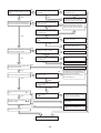
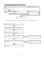
Changes to "Med" or "Lo" from "Hi"
according to the room
temperature.
Operation mode is changed to one
of "Super lo", "Lo", "Med", "Hi",
"Super Hi" and "Stop" according to
the room temperature, time and
heat exchanger temperature.
When the heat exchanger
temperature becomes 18˚C or less
except for the preheating
operation mode, "Stop" is set.
(The operation recovers at 18.66˚C)
Room temp.
Cooling
preset temp.
Auto
Thermostat
judgement
Compressor
Hi
Med
Lo
ON
ON
Compressor
rotates at
maximum speed
during Hot dash
Other than on left
operation or when
recovered from
Heat exchanger temp.
defrosting.
OFF
42.66
37.66
32.66
27.66
1. Operation continues in "Hi"
mode until the thermostat turns
off for the 1st time. ("Super Hi" is
set during Cool dash operation
with the compressor rotating at
maximum speed.)
2. Operates in "Lo" mode when the
thermostat is OFF.
Super Hi
Hi
Med
Lo
"Super Hi" mode operation is done
during Cool dash operation with
the compressor rotating at
maximum speed, and "Hi" mode
operation is done in other modes.
Auto
The following operation mode is
set depending on the room
temperature when the operation is
started.
However, in the auto cooling
mode, the Cool rhythm
operation starts when the room
temperature becomes the
preset temperature + 0.66˚C after
the Dash operation is
completed.
Fan speed mode : AUTO
Fan speed mode : Lo
Fan speed mode : AUTO
Operation mode is changed to one
of "Lo", "Med", "Hi", "Super Hi" and Note
"Stop" according to the room
(1)Mode is not changed after the
temperature and time.
operation is started.
"Super Hi" operation is done when (2)The preset temperature can be
the compressor rotates at
changed within ±3˚C using the
maximum or when recovering from
room temp. control button " "
defrosting.
"V". For example, if the preset
temperature for cooling is
increased by +2˚C to change it
Operation mode is changed to one
to 29˚C, the preset
of "Lo", "Med" and "Stop"
temperature for heating is also
according to the room temperature
changed to 25˚C.
and time.
Also the operation mode
selected from the room
temperature at the start of
Operation mode is changed to one
operation is judged based on
of "Lo" and "Stop" according to
the changed value.
the room temperature and time.
The fan speed is controlled by the
heat exchanger temperature and
overload control is done as shown
below.
Heat exchanger temp.
V
Fan speed mode (Indoor unit)
(Compressor is
forced-stopped
for 3 min.)
Hi
Heating
Cooling
Dehumidifying
Dehumidifying
Cooling
Heating
Operation mode
"Med" mode operation is done
regardless of the room temperature.
Med.
"Lo" mode operation is done
"Lo" mode and "Stop" mode are
regardless of the room temperature. repeated according to the
compressor operation.
32"
Lo
Start/Stop switch
Compressor
Lo
KAFON
KAFOF
Overload
Lo
Refer to page 45.
Refer to page 49.
Refer to page 51 and 53.
Basic mode of
the
temperature
control
Note:
1. Refer to data in Page 41 Table 1 and 2 for each constant shown by capital letters in the diagram.
– 43 –
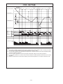
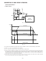
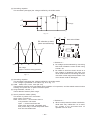
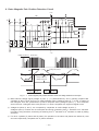
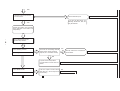
BASIC COOLING OPERATION
Table 1
TCMAX
Preset temperature
for cooling
(+) SHIFTC
Fan speed
"auto" setting
Start
Start/stop switch
Stop
Stop
Start
Thermostat
OFF
Thermostat judgement
650min
750min-1
1.66˚C
2.00˚C
800min-1
2.33˚C
850min-1
2.66˚C
950min-1
3.00˚C
1000min-1
3.33˚C
1050min-1
3.66˚C
1150min-1
4.00˚C
1200min-1
4.33˚C
1250min-1
4.66˚C
1350min-1
5.00˚C
1400min-1
5.33˚C
1450min-1
5.66˚C
1550min-1
6.00˚C
1600min-1
6.33˚C
1650min-1
6.66˚C
Item
External temp. Room temp.
TCMAX
-1
Room temp.
Table 2 Dewing condition judgement value
Max. speed (CMAX) — Room temp. — Preset
Min. speed (CMIN)
temp. (including shift)
CLMXTP
Dewing
condition
Dewing
condition
Dewing
condition
Dewing
condition
Temperature
(ON)
30˚C
(OFF)
32˚C
(ON)
32˚C
(OFF)
34˚C
Super Hi
Hi
Med
Lo
Super Lo
Indoor
unit fan
Note:
1. Refer to data in page 41 Table 1 for each constant shown by capital letters in the diagram.
Operation lamp
Compressor rotation speed
1 min.
Maximum
(CMAX)
Rated
speed
(CSTD)
3 min.
Fixed rotation period
1 min.
3000
Minimum
(CMIN)
0
15 sec.
15 sec.
15 sec.
Outdoor fan
Reversing Valve
(Heating ON mode)
Note:
(1)
Conditions to start Cool dash operation are as follows. When the operation starts with the "AUTO" or "Hi" fan speed or when the fan speed is changed to "Hi" during cooling operation, if the temperature difference between the room
temperature with the compressor rotating at maximum speed and the preset temperature is ( TCMAX: refer to Table 1) or more, Cool dash will start.
(2) Conditions for releasing Cool dash operation (compressor maximum rotation speed period) are as follows.
1 Cool dash has been continued for 25 minutes.
2 The room temperature reaches the cooling preset temperature (including cooling shift value) -1˚C and then the room temperature ≥ preset temperature -0.66˚C is reached after the fixed rotation period has elapsed.
3 The thermostat is turned OFF.
(Ehen Cool dash is released by above 1, Pl control starts without operating for fixed rotation period.)
(3) The thermostat OFF temperature during Cool dash operation is cooling preset temperature (including cooling shift value) +3˚C, and after the thermostat is turned OFF, Cool dash is finished and Pl control starts.
(4) The minimum ON time of the compressor is 3 minutes, and minimum OFF time is also 3 minutes.
(5) The compressor speed in the fixed rotation period after releasing Cool dash maximum speed is the minimum speed (CMIN).
(6) The time limit to keep the maximum speed (CMAX) of the compressor in the normal cooling operation (other than Cool dash) is within 60 minutes when the room temperature is CLMXTP or less. If the room temperature is more than
CLMXTP, there is no time limit.
(7) When the fan speed setting of the remote control is "Med", the maximum compressor speed is CJKMAX.
(8) When the fan speed setting of the remote control is "Lo", the maximum compressor rotation speed is COZMAX.
(9) When the fan speed setting of the remote control is "Hi", and both the room temperature and external temperature (data from the outdoor unit) satisfy the dewing condition shown in Table 2, the maximum compressor speed is
CKYMAX. (This control is effective only when external temperature data is provided.)
– 45 –
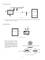
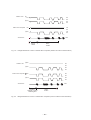
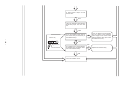
Cooling defrost
Dehumidifying
Indoor unit heat exchager temperature
30 sec. Room temperature
judgement
Room temperature
TEIOF
TEION
Cooling preset
temperature
Thermostat
judgement
Hi
Indoor fan
Med
Lo
Room temperature
judgement
Thermostat OFF
Refer to the basic operation.
15 sec.
Outdoor fan
30 sec.
Start/Stop Switch
Operation lamp
minimum 3 min.
Low humidity
Humidity judgement
High humidity
Thermostat judgement
Hi
Indoor fan
Med
Lo
Hi
Outdoor fan Med
Lo
5 min. OFF/1 min. ON
6 min. OFF/1 min. ON
32 sec.
Compressor rotation
speed
32 sec.
15 sec.
15 sec.
15 sec.
1 min.
3000
min-1
15 sec.
Note: (1) Compressor stop time is 3 minutes minimum.
Reversing valve
Compressor
rotation speed
1 min.
1 min.
1 min.
1 min.
3000
SDMAX
SDRPM
Note:
1. Refer to data in page 41 Table 1 for each constant shown by capital letters in the diagram.
Note:
(1) 30 seconds after the operation is started, when the room temperature is (cooling preset temperature) – (1.33˚C) or less, the operation is done assuming as the preset
temperature = (room temperature at the time) – (2˚C).
(2) The indoor fan is operated in the "Lo" mode, OFF for 5 minutes and ON for 1 minute (at high humidity) or OFF for 6 minutes and ON for 1 minute (at low humidity),
repeatedly according to the humidity judgement when the thermostat is turned OFF.
(3) When the operation is started by the themostat turning ON, the start of the indoor fan is delayed 32 seconds after the start of compressor operation.
(4) The compressor is operated forcedly for 3 minutes after operation is started.
(5) The miniumu ON time and OFF time of the compressor are 3 minutes.
– 49 –
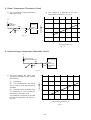
COOL RHYTHM
Room temp.
Minimum
5 min.
Final Preset temperature
5 min.
Minimum 5 min. 5 min.
Minimum
Minimum
Minimum
5 min.
5 min.5 min. 5 min. Minimum 5 min. 5 min. 5 min.
Cooling Preset
temperature (normal)
Cooling Preset
temperature (rhythm)
Thermostat OFF
Thermostat judgement
COOL
RHYTHM
1cycle
Hi
Indoor fan
Med
Refer to the basic
operation
5 sec.
2.5 sec.
Lo
2.5 sec.
Outdoor fan
5 sec.
2.5 sec.
15 sec.
Lo
2.5 sec.
Compressor rotation
speed
Note:
(1) Cool rhythm operation starts during the cooling operation in the AUTO operation mode, not during Cool dash,
and when the room temperature is the preset temperature +0.66˚C or less.
(2) In Cool rhythm operation, the temperature rising period is 10 minutes (minimum) and also temperature falling
period is 10 minutes (minimum).
(3) The Cool rhythm operation is not done during Nice temperature, Sleep and Cool dash operations.
(4) In Cool rhythm operation, Pl control is done and the compressor rotation speed limit is the same as in normal
operation.
(5) When the thermostat is turned OFF, the shifting of the preset temperature in Cool rhythm operation is done.
– 47 –
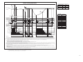
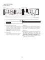
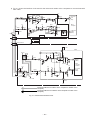
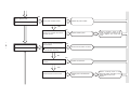
Basic heating operation
Table 1 Speed specification during fixed rotation period
Std
#td (Hot dash time) Wtd1
Wtd2
SFTDSW
Less than 10 minutes 2150min-1 1700min-1
10 minutes to less
3150min-1 2500min-1
than 20 minutes
20 minutes or more 4150min-1 3300min-1
Preset temperature
for heating
(+)SHIFTW
Table 2 #TWMAX
Max. speed (WMAX) – Preset temp. (including
Min. speed (WMIN)
shift) – Poom temp.
"AUTO" fan mode is setting
Start/Stop Switch
Thermostat judgement
Defrost signal
Preheating judgement
Super Hi
Hi
Indoor fan
Med
Lo 10’
Super Lo
stop
Start
stop
start
start
Thermostat OFF
3’ max.
Preheating released
Preheating released
30’
30’
stop
Thermostat OFF
Thermostat
OFF
30’
15’
Controlled by heat exchanger temperature
30’
30’
30’
Controlled
by heat
15’
exchanger
temperature
30’
10’
10’
10’
30’
Controlled
by heat
15’
10’
Controlled by heat
exchanger temperature
15’
exchanger
temperature
Controlled
by heat
exchanger
temperature
15’
Reversing valve
Operation lamp
Compressor rotation speed
1’
10’
10’
Maximum
650min-1
750min-1
800min-1
850min-1
950min-1
1000min-1
1050min-1
1150min-1
1200min-1
1250min-1
1350min-1
1400min-1
1450min-1
1550min-1
1600min-1
1650min-1
1.66˚C
2.00˚C
2.33˚C
2.66˚C
3.00˚C
3.33˚C
3.66˚C
4.00˚C
4.33˚C
4.66˚C
5.00˚C
5.33˚C
5.66˚C
6.00˚C
6.33˚C
6.66˚C
(WMAX)
Fixed rotation
period 1
Rated value
(WSTD)
Fixed rotation
period 2
Wtd1
Wtd2
3000
Minimum
(WMIN)
0
3’
15’
15’
15’
15’
15’
Outdoor fan
Note:
(1) Conditions for starting Hot dash operation are as follows. When the operation starts from the “AUTO” or “Hi” fan speed or when the fan speed is changed to “Hi” during heating operation. If the temperature difference between the
room temperature with the compressor rotating at maximum speed and the set temperature is (#TWMAX : refer to Table 2) and present room temperature is 10˚C or less, Hot dash will start.
(2) Conditions for releasing Hot dash operation (compressor maximum rottion speed period) are as follows.
The limit time for compressor maximum speed operation is exceeded.
The room temperature reaches the heating preset temperature (including heating shift value) + SFTDSW.
The thermostat is turned OFF. (When Hot dash is released by above , PI control starts without operating fixed speed periods 1 and 2.)
(3) The thermostat OFF temperature during HOT dash operation is heating preset temperature (including heating shift value) + SFTDSW + 3˚C, and after the thermostat is turned OFF, Hot dash is finished and the PI control starts.
(4) The minimum ON time of the compressor is 3 minutes, and minimum OFF time is also 3 minutes.
(5) The compressor speeds in the fixed speed perids 1 and 2 after releasing the Hot dash maximum rotation (Wtd1 and Wtd2) are determind as in Table 2 depending on the maximum rotation holding time (#td).
(6) The time limit to hold the maximum rotation (WMAX) of the compressor in the normal heating operation (other than Hot dash) is within 60 minutes when the room temperature is 18˚C or more. If the room temperature is less than
18˚C, there is no time limit.
(7) During initial cycle operation, preheating operation, defrosting (including balancing operation after defrosting) or AUTO-FRESH defrosting, the operation lamp will blink at intervals of one second.
(8) Preheating operation is determined as follows; preheating comes on when heat exchanger temperature <YNEOF - 0.66˚C when operation is started with start / stop switch; preheating mode is released when heat exchanger
temperature> YNEOF.
(9) Rotation speed of compressor is limited to the value of Rating for Heating (WSTD) + 2000 / 2 min-1 or less in “Low” fan operation mode.
(10) In “Super Low” fan operation mode, when room temperature drops below 18˚C, indoor fan operation will stop. When room temperature reaches 18˚C + 0.66˚C, Super Low fan operation will start again. However during preheating
or preheating after defrosting, Super Low fan operation will not stop even if room temperature drops below 18˚C.
1
2
3
1
Note:
1. Refer to data in Table 1 in page 41 for each constant shown by capitital letters in the diagram.
2. [’ ] means minute and [” ] means second (ex. 30’ , 50”) in the diagram.
– 51 –
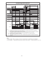
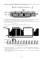
Reversing valve defrost
More than 15’
More than DFTIM
30’
30’
Fan speed
"Hi" setting
Start/Stop switch
AUTO FRESH DEFROST
Stop
Defrost signal
Preheating judgement Preheating OFF
Hi
Med
Indoor fan
10’
Lo
Super Lo
Lo
Outdoor fan
15’
Lo
Operation lamp
Reversing valve
(Power ON mode
in heating)
Deceleration
period
30’
Defrost
period
Max. 12’
TDF TDF TDF TDF
411 412 413 421
TDF4
31
1’
Defrost
period
Max. 3’
3’
Max. 12’
1’
WMAX
3000 2400 1950
TDF
422
3000
3000
SGMNRP
0
Note:
(1)
(2)
(3)
(4)
(5)
The DEFROST inhibit period is DFTIM. After DEFROST is completed, defrost signal is not accepted for
DFTIM. However, first inhibit period is fixed at 40 ninutes.
If the temperature difference between the room temperature and set temperature is great after the DEFROST
is completed, compressor can keep maximum rotation speed (WMAX) for up to 120 minuets.
DEFROST period is a maximum 12 minutes.
When operation is stopped during DEFROST, the mode switches to AUTO FRESH DEFROST.
AUTO FRESH DEFROST does not work within 15 minutes after the operation is started or after DEFROST is
completed.
Note:
1. Refer to data in Table 1 on page 41 for each constant shown in capital letters in the diagram.
2. In the diagram, s’ attached to the top right of number mean minute, s” means second. (ex. 30’, 15”)
– 53 –
AUTO SWING FUNCTION
INPUT SIGNAL
PRESENT CONDITION
OPERATION
STOP
OPERATION MODE
AIR DEFLECTOR
STOP
ONE SWING (CLOSING AIR DEFLECTOR)
1 DOWNWARD
2 UPWARD
DURING ONE SWING
STOP AT THE MOMENT.
STOP
START SWINGING
1 DOWNWARD
2 UPWARD
3 DOWNWARD
DURING SWINGING
STOP AT THE MOMENT.
STOP
START SWINGING
1 DOWNWARD
2 UPWARD
3 DOWNWARD
DURING SWINGING
STOP AT THE MOMENT.
TEMPORARY STOP
START SWING AGAIN.
DURING SWINGING
STOP SWINGING TEMPORARILY.
(SWING MODE IS CLEARED IF SWING COMMAND IS
TRANSMITTED DURING TEMPORARY STOP.)
COOL
FAN
DRY
STOP
DURING ONE SWING
INITIALIZE
1 DOWNWARD
2 UPWARD
HEAT
CIRCULATOR
STOP
DURING ONE SWING
INITIALIZE
1 DOWNWARD
EACH MODE
KEY INPUT
AUTO COOL
COOL
FAN
AUTO DRY
DRY
DURING
OPERATION
– 54 –
AUTO HEAT
HEAT
CIRCULATOR
THERMO. ON
(INTERNAL FAN
ON)
THERMO. OFF
(INTERNAL FAN
OFF)
MAIN SWITCH
ON
DURING
OPERATION
STOP
OPERATING SPECIFICATION
AUTO DRY
DRY
AUTO HEAT
HEAT
CIRCULATOR
MAIN SWITCH
OFF
DURING
OPERATION
EACH MODE
CHANGE OF
OPERATION
DURING
OPERATION
EACH MODE
STOP
DURING SWINGING
DURING
INITIALIZING
ONE SWING (CLOSING AIR DEFLECTOR)
1 DOWNWARD
2 UPWARD
STOP
INITIALIZING CONDITION OF EACH MODE.
DURING SWINGING
STOP SWINGING AND MODE BECOMES INITIALIZING
CONDITION.
REFERENCE
INITIALIZE AT NEXT
OPERATION.
INITIALIZE AT NEXT
OPERATION.
DESCRIPTION OF MAIN CIRCUIT OPERATION
Model RAS-25CNH11
1. Reset Circuit
R211
ZD202
HI
LO
17 RES
C202
–
Q202
NORMAL
RESET
R204
+
Q201
R208
C201
ZD201
R202
5V
R210
R203
R209
R201
5V 12V
D201
35V 5V
MICRO
COMPUTER
0V
Fig. 1-1
Voltage
35V DC line
35V
24V
5V DC line
5V
Base of Q201
Power is ON
Power is OFF
5V
Collector of Q202
Fig. 1-2
●
The reset circuit initializes the program when power is supplied or power is restored following a power failure.
●
RESET “Lo” or SET “Hi” activates the micro computer.
●
Fig. 1-2 shows the waveforms in each circuit when power is ON and OFF.
●
When the power is supplied, the voltages on the 35V and 5V DC lines rise, and when the 35V DC line becomes approx.
24V, ZD201 turns on and the voltage at the base of Q201 rises to turn Q201 on. Since the collector of Q201 goes “Lo”
at this time, Q202 turns on and the reset input of the micro computer goes “Hi”. The 5V DC line has already been 5V
at this time and the micro computer starts operation.
●
When power is OFF, the voltage on the 35V DC line drops, and when it is approx. 24V, ZD201 turns off, Q201 and Q202
turn off, and the reset input of the micro computer goes “Lo” to reset it.
– 55 –
2. Receive Circuit
12V
R709
+
–
LIGHT
RECEIVING
UNIT
0V
C701
R710
ZD701
0V
18 Wireless input
R705
C702
0V
Micro computer
0V
Fig. 2-1
●
The Light receiving unit receives an infrared signal from the wireless remote control. The receiver amplifies
and shapes the signal and outputs it.
3. Buzzer Circuit
12V
R801
Micro computer
Buzzer output
BZ BZ1
21
Q805
0V
Fig. 3-1 Buzzer Circuit
●
When the buzzer sounds, an approx.
3.9kHz square signal is output from
buzzer output pin
of the micro
computer. After the amplitude of this
signal has been set to 12Vp-p by a
transistor, it is applied to the buzzer.
The piezoelectric element in the
buzzer oscillates to generate the
buzzer’s sound.
q
Metal diaphragm
Pizoelectric element
V
Sound wave
Fig. 3-2 Buzzer Operation
– 56 –
V
4. Auto Sweep Motor Circuit
12V
CN4
Micro computer
51
4
13
50
3
14
49
48
2
15
1
16
8
Auto sweep motor for
horizontal air deflectors
Rotor
IC501
0V
Fig. 4-1 Auto Sweep Motor Circuit (Horizontal air deflectors)
●
Fig. 4-1 shows the Auto sweep motor drive circuit; the signals shown in Fig. 4-2 are output from pins
– of the micro computer.
k A
Micro computer pins
Horizontal air
deflectors: 10ms.
Step width
Horizontal air deflectors
1
2
3
4
5
6
7
8
51
50
49
48
Fig. 4-2 Micro computer Output Signals
●
As the micro computer’s outputs change as shown in Fig. 4-2, the core of the auto sweep motor is excited
to turn the rotor. Table 4-1 shows the rotation angle of horizontal air deflectors.
Table 4-1 Auto sweep Motor Rotation
Horizontal air deflectors
Rotation angle per step (° )
Time per step (ms)
0.0879
10
– 57 –
5. Room Temperature Thermistor Circuit
●
Fig. 5-1 shows the room temperature
thermistor circuit.
The voltage at A depends on the room
temperature as shown in Fig. 5-2.
●
5
5V
4
Micro
computer
R309
Voltage at A (V)
Room
temperature
thermistor
3 Room
temp. input
C302
R310
A
0V
0V
3
2
Fig. 5-1
1
0
0
10
20
30
40
Room temperature (˚C)
Fig. 5-2
6. Heat exchanger temperature thermistor circuit
5V
Heat exchanger
temperature thermistor
Micro computer
R307
4 Heat
exchanger
C301
temperature
input
0V
R308
A
0V
Fig. 6-1
The circuit detects the indoor heat
exchanger temperature and controls
the following.
(1)
5
4
Preheating.
(2) Low-temperature defrosting
during cooling and dehumidifying
operation.
(3) Detection of the reversing valve
non-operation or heat exchanger
temperature thermistor open.
Voltage at A (V)
●
3
2
1
The voltage at A depends on the heat
exchanger temperature as shown in
Fig. 6-2.
0
-10
0
10
20
Heat exchanger temperature (˚C)
Fig. 6-2
– 58 –
30
40
7. Temporary Switch
12V
TEMPORARY SWITCH
SW701
R709
ZD701
C701
0V
R710
0V
R603
37 X1
MICRO COMPUTER
0V
Fig. 7-1
7-1
Fig.
●
The temporary switch is used to operate the air conditoner temporarily when the wireless remote control
is lost or faulty.
●
The air conditioner operates in the previous mode at the previously set temperature. However, when the
power switch is set to OFF, it starts automatic operation.
8. DC Fan Motor Drive Circuit
●
Fig. 8-1 shows the indoor DC fan motor drive circuit.
J
35V
Q903
R902
L901
R905
D901
R904
Micro computer
5
4
3
2
1
5V
0V
C901
R901
C942
R903
0V
R921
Fan PMW output 57
Q904
R920
CN10
0V
I
RED
YEL
M
BLU
Indoor DC
Fan motor
0V
Output divider 8
0V
R930
C940
0V
R906
0V
Fan current
9
detection
R909
R931
R932
R910
R915
5V
C933
D902
0V
Terminal board D
Fig. 8-1
8.1
Fig.
●
The circuit produces the fan motor drive voltages, 8-33V, from 35V DC supplied from the outdoor unit and
controls the fan motor speed.
●
Q903 is switched on and off according to the signal at fan PWM output pin
is smoothed by D901, L901 and C901 to drive the fan motor.
●
The output voltage is divided by R901 and R903 and is input to divided voltage output pin ; the micro
computer controls the fan PWM output so the output voltage is set to the specified value. The chopper
frequency of the fan PWM output is 15.7kHz.
●
In the Fan current detection circuit, 35V line current is detected by R906`R915 and input to fan current
detection pin . Microcomputer detects overcurrent comparing it with the current judgment value
corresponding to the fan rotation speed.
9
– 59 –
J to control the voltage which
8
PWM output
Voltage at I
Voltage at J
Output voltage
Fig. 8-2
Fan Motor Set Wind Velocity and DC Voltage (between blue and red) Characteristics
COOLING
DEHUMIDIFYING
INDOOR FAN SPEED
HEATING
Mode
Fan Speed
Connector blue-red voltage (V)
Rotation Speed (min-1)
SS
9.8
714
S
16.6
950
OVERLOAD
19.1
1,040
LO
19.1
1,040
HI
27.7
1,350
SUPER HI
27.7
1,350
S
16.0
930
LO
18.7
1,020
HI
20.9
1,100
SUPER HI
20.9
1,100
S
16.0
930
– 60 –
9. 12V Power Circuit
35V
R101
R104
REG1
8
1
7
2
6
3
5
4
B
L102
12V
A
D102
+
R102
C102
–
C105
0V
0V
0V
Fig. 9 — 1
R103
0V
0V
●
DC 35V supplied from the outdoor unit is controlled by switching of regulator 1, and is smoothed by D102,
L102 and C102 to produce 12V.
●
Output voltage is divided by R102 and R103, and input to output dividing pin
that output voltage is 12V.
Waveform at
A
Waveform at
B
Out put Voltage
Fig. 9 — 2
– 61 –
5 to control switching, so
Model RAC-25CNH11
1. Power Circuit
Black
Green
15A fuse
‡
‡
0
Varistor 1
Surge
absorber
0
C807
0
0 0 0
0
C805
C806
0
Varistor 3
B
White
0
C808
0
£ £
‡ ‡
0
C812
0
^
NF coil
0
0
1
Inrush current
protection relay
R807
0
‡ ‡ 0
Power relay
0
1
0 0
0 0
R802
zzz
0
‡ ‡
C813
0
Reactor
£ £
1
R801
zzz
0
0 0
R806
0
!
Power module
A
Diode stack
Stick relay
£ £
£ £
Terminal
board
0V
L804
DC voltage DC current
detection detection
circuit
circuit
This circuit full-wave rectifies 220V AC applied between terminals A:B to produce a DC voltage of
220 x !2= 310V
at the positive and negative terminals. However, the voltage is approx. 260-290V when the compressor
is operating.
t
●
The following describes the main parts components.
TT
(1) Reactor and power capacitor
< Reference >
The filter consisting of a reactor and power
● If the reactor is faulty or the connection is defective,
capacitor removes high harmonics
the compressor may stop due to “abnormality in
components from the current containing
line voltage”, etc. immediately after it is started.
high harmonics occurring when the
compressor is operating to improve the
< Reference >
power factor.
● When diode become defective, the compressor may
stop due to” abnormality in line voltage”, etc.
(2) Diode stacks
immediately after it is started or no operation may
These rectify the 220V AC from terminal
be done as a DC voltage is not generated between
boards A and B to a DC power supply.
the positive ! and negative @ terminals.
● When diode stack becomes defective, check
whether the 15A fuse has blown.
●
– 62 –
(3) Smoothing capacitor
This smoothes (averages) the voltage rectified by the diode stacks.
A
0
£ £
‡
0
‡
0
!
0
1
1
zzz
zzz
2
a
B
0
£ £
0
VD
(DC valtage)
2
0
£ £
0
@
0
0
Fig. 1-2
@
V
!
Both ends of R802
DC voltmeter or teste
(same as oscilloscop)
a
0V
Fig. 1-4
VD
DC voltage
(approx. 260-290V during operation)
0V
Fig. 1-3
< Reference >
● DC voltage can be measured by connecting
both ends of R802 the control P.W.B. using
a tester, etc.
● Be careful to avoid an electric shock as a
high voltage is generated. Also take care
not to cause a short-circuit through incorrect
connection of test equipment terminals. The
circuit board could be damaged.
(4) Smoothing capacitor
This smoothes (averages) the voltage rectified by the diode stacks.
A DC voltage is generated in the same way as in Fig. 1-3.
(5) C805 - C808, C812, C813, L804 (NF coil)
These absorb electrical noise generated during operation of compressor, and also absorb external noise
entering from power line to protect electronic parts.
(6) Surge absorber, varistor 1, 3
These absorbs external power surge.
(7) Inrush protective resistor (R807)
This works to protect from overcurrent
when power is turned on.
R807 Short-circuit → Overcurrent flows in
rush protection ON mode
Open → Overcurrent flows with
power relay turned ON. (damaged each
time power relay is turned ON) Diode stack
and 15A fuse deteriorate.
– 63 –
< Reference >
● When inrush protective resistor is defective,
diode stack may malfunction. As a result,
DC voltage is not generated and no
operation can be done.
2. Indoor/Outdoor Interface Circuit
●
The interface circuit superimposes an interface signal on the 36V DC line supplied from the outdoor unit
to perfom communications between indoor and outdoor units. This circuit consists of a transmiting circuit
which superimposes an interface signal transmit from the micro computer on the 35V DC line and a
transmiting circuit which detects the interface signal on the 35V DC line and outputs it to the micro
computer.
●
Communications are performed by mutually transmiting and receiving the 4-frame outdoor request signal
one frame of which consists of a leader of approx. 100 ms., start bit, 8-bit data and stop bit and the
command signal with the same format transmit from the indoor unit.
●
Outdoor micro computer to indoor micro computer
Request signal output from IF transmitting output pin 64 of outdoor microcomputer input to transmitting
circuit. Transmitting circuit and receiving circuit of the outdoor unit are provided inside HIC. Transmitting
circuit intermits high frequency oscillation circuit of about 36kHz with comparator according to the request
signal. This high frequency signal is applified by the transistor and is ourput from HIC = pin, then
superimposed with DC 35V line via C701 and L701.
To prevent mis-operation, outdoor microcomputer does not accept receive signal whil outputting request
signal.
The receiving circuit of the indoor unit consists of COM4. The interface signal from the outdoor unit, whose
DC component is cut from DC35V line at C801, is waveform-shaped and rectified amplified in HIC, then
input to receive input pin ( of indoor microcomputer.
Fig. 2-2 shows the voltages at each component when data is transferred from the outdoor microcomputer
to the indoor microcomputer.
●
Indoor micro computer to outdoor micro computer
The communications from the indoor micro computer to the outdoor micro computer are the same. Fig.
2-3 shows the voltages and waveforms at each circuit.
– 64 –
●
Fig. 2-1 shows the interface circuit used for the indoor and outdoor micro computers to communicate with
each other.
5V
5V
C801
5V
5V
COM801
R805
R803
9
R807
14
R804
8
D801
12
R802
C802
OV
OV
D101
5V
13
R822
Q802
OV
5V
R817
R821 R807
R815
C807
OV
OV
Q801
R813
R809
OV
5V
R813
C805
C803
R814
-
R818
D
C
R819
11
+ 10
IF transmit
64 output
(SDO)
COM801
HIC
OV
Terminal board
C
Micro
computer
R820
OV
D
IF receive
19 input
(SDI)
C804
R811
OV
R806
OV
5V
R810
R808
OV
C806
OV
OV
Inpoor P.W.B.
Outdoor P.W.B.
Terminal board
C703
42
I/F35V
HIC-l
OV
43
5V
OV
5V
5V
5V
L701
+
R702
-
41
C701
IF transmit
64 output
(SDO)
R703
OV OV
Micro
computer
AX-8E21
OV
OV
12V
5V
5V
5V
5V
IF receive
21 input
(SDI)
R704
OV
40
+
-
C702
C709
C706
Noise filter
coil
OV
C710
OV
OV
OV
C708
I /F GND
OV
OV
39
C704
OV
(Communications from indoor micro computer to outdoor micro
computer)
(Communications from outdoor micro computer to indoor micro
computer)
Fig. 2-1 Indoor/outdoor interface Circuit
– 65 –
5V
0V
| |
%Pin
5V
0V
| |
$Pin
Pin
5V
0V
(Pin
5V
0V
| |
Outdoor HIC
35V
Indoor micro computer
35V DC line
11
33ms.
100 ms.
Leader
Fig. 2-2
1frame
Voltages Waveforms of indoor / Outdoor Micro computers (Outdoor to Indoor Communications)
Outdoor HIC
$Pin
5V
0V
%Pin
5V
0V
Indoor micro computer
Pin
5V
0V
(Pin
5V
64
0V
35V DC line
35V
11
4.95ms.
Transmit / receive
switching time
Fig. 2-3
33ms
1frame
Voltages Waveforms of indoor / Outdoor Micro computers (Indoor to Outdoor Communications)
– 66 –
●
‡
‡
– 67 –
0
0
0
0
Power relay
‡ ‡
0
Inrush
current
protection
R807 relay
‡ ‡
C813
C812
Stick relay
‡ ‡
0
|
1
0
0
80 µ F
2
zzz
0
zzz
1000 µ F
2
1
0
0
0
0
R802
2
!
1
1
DC current (Id)
detect resistance
R801
0
Fig. 3-1 Power module circuit (U+ is ON, V is ON)
0
£ £
0
£ £
0
£
L804
0
|
C805
0
Diode stack
Reactor
£
‡
‡
FUSE(15A) Noise Filter
Coil
0
u- 0
0
0
0
u+0
0
0
£
£
0
v- 0
0
0
v+0
0
0
£
£
0
w- 0
0
0
w+0
Power Module
£
£
3
5
7
V
W
u
Fig. 3-1 shows the power module and its peripheral circuits.
The three transistors on the positive e side are called the upper arm, and the three transistors on the negative d side, the lower arm.
W coil
DC compressor
Motor
V coil
U coil
3. Power Module Circuit
●
DC 230V is input to power module and power module switches power supply current according to rotation
position of magnet rotor. The switching order is as shown in Fig. 3-2.
[
]
* At point E: U+ is ON, V– is ON (circuit in Fig. 3-1)
* At point F: U+ is chopped (OFF), V– is ON (circuit in Fig. 3-4)
E
V+
W+
F
V+
U+
Upper arm
transistor
Lower arm
transistor
U —
W—
V—
W—
U—
Time
T
Fig. 3-2 Switching order of power module
●
Upper arm transistor is controlled to ON/OFF by 3.2kHz chopper signal. Rotation speed of the compress
is proportional to duty ratio (ON time/ ON time + OFF time) of this chopper signal.
●
Time T in Fig. 3-2 shows the switching period, and relation with rotation speed (N) of the compressor is
shown by formula below;
N = 60/2 X 1/T
●
Fig. 3-3 shows voltage waveform at each point shown in Figs. 3-1 and 3-4.
U+ transistor chopped
Voltage between
A and B
U transistor ON
260V-380V
Chopping period
T
Chopping period
Upper arm transistor
current at
ON
B
Fig. 3-3 Voltage waveform at each point
●
When power is supplied U+ [ U–, because of that U+ is chopped, current flows as shown below; B
(1) When U+ transistor is ON: U+ transistor [ U coil [ V coil [ V– transistor [ DC current detection
resistor [ Point B (Fig. 3-1)
When U+ transistor is OFF: (by inductance of motor coil) U coil [ V coil [ V– transistor [ Return diode
[ Point A (Fig. 3-4)
– 68 –
Power module
‡
0
!
‡
U+
0
0
0
0
0
0
0
£
V+
£
0
W+
£
A
0
DC compressor
motor
U coil
U
1
zzz2
V
1000 µ F
W
B
R806
0
‡
@
‡
£
U0
£
V0
DC current (Id)
detection resistor
£
W-
0
0
V coil
0
W coil
MP6501
Fig. 3-4 Power module circuit (U+ is ON, V– is ON)
●
Since current flows at point B only when U+ transistor is ON, the current waveform at point B becomes
intermittent waveform as shown in Fig. 3-3. Since current at point B is approximately proportional to the
input current of the air conditioner, input current is controlled by using DC current (Id) detection resistor.
<Reference>
If power module is detective, self diagnosis lamps on the control P.W.B. may indicate as shown below:
Table 3-1
Control P.W.B.
Self-diagnosis lamp
Self-diagnosis
and mode
LD301 Red
LD302 Red
LD303 Red
}
lp (peak current cut)
LD301
Blinks 2
times
Abnormal low speed
rotation
LD301
Blinks 3
times
Switching incomplete
LD301
Blinks 4
times
Switching incomplete
LD301
Blinks 10
times
Self-diagnosis lamps
Fig. 3-5
●
Simplified check of power module (Lighting mode when operated with compressor leads disconnected)
(1) Disconnect connector of 3-pole (WHT, YEL, RED) lead wire connecting to compressor located at the
lower part of electric parts box.
(2) Set to compressor operation state (other than FAN mode) and press Start/stop switch of remote
control.
(3) If normal operation continues for more than 1 minute (LD303 lights), power module is considered
normal.
❈ Refer to other item (troubleshooting on page 91) for independent checking of power module.
– 69 –
4. Power Circuit for P.W.B.
●
Fig. 4-1 shows the power circuit for P.W.B. and waveform at each point.
D61
C61
D62
C62
D63
3A fuse
C810
R805
AC 220V
C3
Q1
R5
R6
c
(12 - C)
d
(12 - D)
(12 - D)
g
(12 - E)
(12 - E)
C64
h
(12 - H)
RC61
C
M52
C65
C2
C811
R4
D2
(12 - C)
f
D64
D1
R2
L1
C1
(12 - C)
b
e
C63
R3
R1
a
Q2
C5
VR2
ZD3 R8
D4
D65
R9
12V
5V
0V
C66
—5V
C4
C711 R62
R64
I / F 35V
RC62
C67
C6
C712
R51
1
R52
P151
3
2
M51
C51
4
R63
I / F GND
R53
R54
Fig. 4-1 Power circuit for P.W.B.
●
In the power circuit for P.W.B., power voltage for microcomputer, peripheral circuits, and power module
drive and, as well as DV35V, are produced by switching power circuit.
●
Switching power circuit performs voltage conversion effectively by switching transistor Q1 to convert
DC270V voltage to high frequency of about 20kHz to 70kHz.
●
Transistor Q1 operates as follows:
(1) Shifting from OFF to ON
●
DC about 270V is applied from smoothing capacitors C810 ! and C811 @ in the control power circuit.
With this power, current flows to base of transistor Q1 via R1 and Q1 starts to rurn ON. Since voltage in
the direction of arrow generates at point C at the same time, current passing through R5, R6 and D2 is
positive-fed back to Q1
– 70 –
(2) During ON period
● Collector current of Q1 is increased directly. In this period, base current is fixed by saturation characteristic
of transformer.
(3) Shifting from ON to OFF
● In this circuit, feed back (negative) is applied from 12V output. When voltage between both ends of C65
reaches the specified value, M51 is turned ON and current flows between pin 1 and 2 of P151, secondary
side is turned ON, current flows to base of Q2 via R9 and D4, Q2 is turned ON, and Q1 base current is
bypassed to turn Q1 OFF.
(4) During OFF period
● During Q1 ON period, energy as shown below is charged at primary winding of transformer and is
discharged to each secondary coil during OFF period:
Energy = LI2/2.
L : Primary inductance
I : Current when Q1 is OFF
Each coil C61 - C67 is charged according to the winding ratio.
ZD3 turns ON Q2 to bypass Q1 base current during ON period to fix value of voltage in the direction of
arrow.
For example, when applied voltage to Q1 is high, voltage in the direction of arrow will rise, and current
bypassing to Q2 is increased.
● Overcurrent flows at Q1 due to charged current at C61 - C67 when starting operation.
● When ZD3 reaches On voltage as a result of the voltage generated in the direction of arrow by Q1 collector
current, Q2 is turned ON and Q1 base current is bypassed.
● By limiting base current with Q2, Q1 is prevented from allowing too much collector current to flow.
– 71 –
<Reference>
•
When power circuit for P.W.B. is estimated as abnormal:
(1) Check that power voltages of 5V, 12V on the control P.W.B., and also power voltage of upper arm
U, V and W and lower arm are specified values.
PQ601 603
•
Test pin
•
PQ501 503
CAUTION
DC voltmeter
or tester
When measuring drive
voltage, if short-circuited
between pins, it could be
damaged.
@
V
!
8
Check 5V (±0.5V), 12V
+ 1V
- 1 . 5 V using test pin.
(
(
( +-
1V
1.5V
( and @ 5V
Check as follows to measure power voltage of upper
arm (U,V,W) and lower arm drive circuit:
a) U phase of upper arm
Apply ! terminal of tester to pin 8 of PQ501
Apply @ terminal of tester to pin 7 of PQ502
b) V phase of upper arm
Apply ! terminal of tester to pin 8 of PQ501
Apply @ terminal of tester to pin 7 of PQ502
c) W phase of upper arm
Apply ! terminal of tester to pin 8 of PQ503
Apply @ terminal of tester to pin 7 of PQ503
d) Lower arm
Apply ! terminal of tester to pin 8 of PQ601
Apply @ terminal of tester to pin 7 of PQ602
1
CAUTION
For PQ501 — PQ503 and
PQ601 — PQ603, apply !
terminal to pin 8, @ terminal
to pin 7. If short-circuited
between pins, it could be
damaged.
CAUTION
Be careful not to short-circuit by touching of
tester terminals, etc.
Fig. 4 - 2
(2) Abnormal only when output of 5V voltage has decreased:
Regulator 1 is abnormal, short-circuited between 5V and 0V, or output too high.
(3) When 12V and 5V voltage are abnormal:
1 Mainly;
2 Fan, operation, power, or inrush current protective relays (short-circuit inside relay, etc.)
3 HIC abnormal
Regulator 1 abnormal, etc.
Primary side short-circuited.
When secondary side is short-circuited, primary side is normal because of overcurrent protective
device
Voltage rise when primary side is open, feed back system abnormal.
(4) When each phase of upper arm U, V, W or lower arm power is abnormal:
D61 - D65, RC61, RC62 or drive circuit is abnormal.
(5) When all voltages are abnormal:
Q210, ZD201, R205, etc. may be abnormal.
Be careful, if Q201 is abnormal, other parts such as power module, HIC, regulator could be defective.
– 72 –
5. Reversing valve control circuit
I/F 35V
12V
HIC
CN2
3
0
£
D 701
0
1
R 233
0
£
Reversing
valve
PQ 701
0
Q 701
0
§
0
DC voltmeter
or tester
8E21
R 705
¤
R 706
V
0
I/F 0V
Fig. 5 - 1
❈ Since the reversing valve is differential pressure system, even when reversing valve is ON (collector
●
voltage of Q701 is about 0.8V normally), compressor rotation speed instructed by indoor microcomputer
exceeds 3300min-1, signal at pin 24 of microcomputer changes, and collector voltage of Q701 will be about
36V.
This does not indicate trouble. When rotation speed is reduced under 2700min-1, collector voltage of Q701
will fall to about 0.8V again. To measure voltage, connect Œ terminal of tester to D701 anode and œ
terminal to D line on the terminal board.
By reversing valve control circuit you can switch reversing valve ON/OFF according to instruction from
indoor microcomputer and depending on operation condition.
Voltage at each point in each operation condition is approximately as shown below when measured by
tester. (When collector voltage of Q701 is measured)
Table 5-1
Operation condition
Cooling
Heating
Dehumidifying
Collector voltage of Q701
General operation of Cooling
About 36V
In normal heating operation
About 0.8V
MAX. rotation speed instructed
by indoor microcomputer after
defrost is completed
About 0.8V
Defrosting
About 35V
SENSOR DRY
About 35V
– 73 –
6. Rotor Magnetic Pole Position Detection Circuit
+ 12V
HIC
A
0
R102
R101
zzz
+
0
0
0
£ £ £ £
B
R103
00
0
0
63
C104
zzz
C105
zzz
+
0
61
C106
0
C101
zzz+
R105
0
C103
zzz+
R104
0
C102
zzz+
0
R106
0
0
0
0
0
0
0
60
0
+
-
0
+
-
0
0
0
0
D
0
0
)
0
(_
0
0
0
(_
0
0
C
0
0
57
0
00
0
0
59
58
+
-
00
0
0
62
0
0
0
0
Outdoor
microcomputer
+
0
4
3
0
0
0
0
0
0
0V
_ 5V
Voltage at point A
about 230V
Voltage at point B
0.6V
Voltage at point C
Voltage at point D
B- transistor ON
Fig. 6 - 1
C- transistor ON
B+ transis- C+ transistor ON
tor ON
Rotor magnetic pole position detection circuit and voltage waveform at each part
●
Motor-induced voltage signal (voltage at point A ) is phase-shifted by 90° by passing lowpass filter
consisting of R101, R104 and C101 to make triangular wave (voltage at point B ). In HIC, 3 phases of
this triangular wave are synthesized to produce composite wave (voltage at point C ). This composite
wave becomes a triangular wave with period of 1/3 times compared with original triangular wave.
●
Voltages at points B and C are compared by comparator to make voltage at point D.
Voltage at point D is taken into microcomputer and timing of switching from V– transistor to W– transistor
is made by rising waveform, and timing of switching from V+ transistor to W+ transistor is made by failling
waveform.
●
For other 2 phases (V phase and W phase), the operation is the same and phases are shifted by 120°
and 240° respectively compared with U phase waveform.
– 74 –
7. Drive Circuit
(1) Upper Arm Drive Circuit
●
Fig. 7-1 shows the upper arm drive circuit.
The circuit configuration is completely the same for phases A, B and C.
Fig. 7 - 1
Fig. 7 - 2 Forward Current Waveform at Point A
●
●
When pin ° of HIC goes "Hi" [ "Lo", a photocoupler between PQ501 pins 1 and 2 turns on and current
flows to terminal d [ R501 [ PQ501 [ R504 [ power module’s Bu+ terminals [ Eu+ terminals [
D502 [ D501 [ terminal e and drives the upper arm transistors. (Fig.7-2)
As described in the rotor magnetic pole position detecting circuit, the upper arm drive circuit supplies
current to the bases of the transistors on the power module's positive e side which turn on or off according
to the position detection signals. The signals according to the position detection detection signals are
output from pins ,
and
of the micro computer and are input to pins 2 of photocouplers PQ501 PQ503 via driver IC1.
er
t
– 75 –
●
e
When pin
of HIC-1 then goes "Hi" [ "Lo", a photocoupler between PQ2 pins 1 and 2 turns off and
the reverse bias current flows to C501 [ power module’s Eu+ terminals [ Bu+ terminals [ R504 [
PQ501 Switching incomplete to cut off the upper arm transistors. (Fig.7-3)
a
8
A
R401
1
5
PQ2
2
R404
6
7
R407
D401 D402
+
b
Power module
—
C401
1
Bu+
2
Eu+
A+phase
OA
Reverse
bias
current
Current at point A
Fig. 7-3 Waveform of Transistor Base Current (Reverse Current at Point A )
●
●
R507 is used to charge C501 initally.
The operation is the same for B+ and C+ phases.
– 76 –
(2) Lower Arm Drive Circuit
●
Fig. 7-4 shows the lower arm drive circuit.
The circuit configuration is completely the same for phases A, B and C.
c
2
2
6
7
R414
Bu-
A- phase
R412
8
5
R415
PQ6
Bv-
6
7
B- phase
R413
8
1
2
5
PQ5
1
Power module
R411
8
1
5
PQ7
6
7
R416
R417
Bw-
d
Ew
D411
D412
C- phase
CN28
C411
Fig. 7-4
●
When pin fi of the micro computer goes "Lo" [ "Hi", a photocoupler between PQ601 pins 1 and 2 turns
on and current flows to terminal i [ R601 [ PQ601 [ R604 [ power module's BU– terminals [
Ew– terminals [ D602 [ D601 [ terminal k and drives the lower arm transistors. (Fig. 7-4)
●
The signals which turn on or off according to the position detection signals are output from pins ‹›fi
of the micro computer in the same way as in the upper arm drive circuit and are input to pins 1 of
photocouplers P601 and PQ602 via driver IC1.
●
No chopper signal is input to the lower arm drive circuit.
1
2
1
2
1
2
8
PQ5
7
8
PQ6
7
8
PQ7
7
Power module
R411
5
6
R414
Bu-
A- phase
R412
5
R415
Bv-
6
B- phase
R413
5
6
R416
R417
BwEw
D411
D412
C- phase
CN28
C411
Fig. 7-5
●
When pin fi of the micro computer goes "Hi" [ "Lo", a photocoupler between PQ601 pins 1 and 2 turn
off and reverse bias current flows to C411 [ power module's Ew– terminals [ Bu– terminals [ R604
[ PQ601 to cut off the lower arm transistors. (Fig. 7-5)
●
R607 is used to charge C601 initally.
The operation is the same for B– and C– phases.
●
●
When the peak current cut off function operates, HIC-1 º pins become 0V, PQ501-PQ503 and PQ601PQ603 turn off and the upper/lower arm drive circuits stop.
●
when a reset signal is applied, HIC pins 7 and ¤ become open, PQ501-PQ503 and PQ601-PQ603 turn
off and the upper/lowerarm drive circuits stop.
– 77 –
8. HIC and Peripheral Circuits
●
Fig. 8-1 shows the micro computer and its peripheral circuits, Table 8-1, the basic operations of each
circuit block, and Fig. 8-2, the system configuration.
HIC - 1
Power module positive +
terminal
5V
R229
AVcc 1
Vd 2
R230
0V
64 +
- C204 R231
5V
0V
Micro computer
AX-8E21
ZD301
1
0V
0V
12V
R232
0V
Normal Hi
at Reset Lo
31 Normal Hi
2
RESET 17
0V
0V
5V
m
(7-C)
POR 23
5V
5V
5V
0V
0V
lp 22
R202
0V
0V
Power moule
negative R201 terminal
45
+
0V
44
C202
+
-
0V
COMl(2/4)
D201
ld 3
To upper arm drive circuit
9
5V
5V
R204
ls 4
R208
R203
Q203
47
0V
+
-
7
+
-
C206
0V
3
2
5
6
D202
0V
Cool 44
1
(Current detection
Resistor)
4
VRI
8
+
-
8 0V
Chopper 57
0V
0V
C205
30 Normal
56
7
R806
R205
5V
0V
FANC
0V
R21
R207
Q202
0V
Q201
R222
0V
R206
0V
Fig. 8-1 Micro computer(AX-8E21) and peripheral circuits
Table 8-1
Basic operation
Circuit block
Peak current
cutoff circuit
Detects DC current flowing power module and during overcurrent (instantaneous
value) flows, stops upper/lower arm drive circuits and also produces lp signal by
which drive signal output (HIC 33 _ 38 from microcomputer is stopped.
Set value circuit
Compares voltage detected, amplified and input to HIC with set voltage value in
microcomputer, and controls overload when set value exceeds input voltage.
Voltage amplifier
circuit
Voltage-amplifies DC current level detected by the detection resistor and inputs
this to microcomputer. Internal or external overload is judged in microcomputer.
Reset circuit
Produces reset voltage.
Trip signal
synthesis circuit
Modulates chopper signal to drive signal and stops according to presence/absence of lp signal or reset signal.
– 78 –
Reset voltage
5V
Chopper signal
DC current
Reset circuit
!
Reset Signal
Trip signal
synthesis circuit
Chopper
signal
DC 260V
_ 290V
Outdoor
micro
computer
photocoupler
Ip signal (interrupt signal)
Overload external
set value circuit
Voltage amp.
circuit
Power module
Peak current cut
off circuit
Compressor
motor
(AX-8E21)
DC current level
Drive
signal
@
Detection
resistor
DC current
R806
Fig. 8 - 2
●
The following describes the operations of each circuit in detail.
(1) Peak current cut (Ip) off circuit
Fig.8-3 shows the Peak Current Cut off Circuit and Waveforms at Each Section.
HIC - 1
DC current (ld)
5V
18A
POR 23
31
Normal Hi
5V
5V
Voltage at point A
0.9V
Ip
B
22
C
0V
Micro
computer
AX-8E21
Q1
0V
5V
0V
0V
(A)
R202
45
+
+
-
A
R201
0V 44
R1
C202 D201
0V
COM 1 (2/4)
30
0V
DC current
R806
(current detection
0V resistor)
Normal Hi
56
Micro computer
Voltage at pin
chopper
7
Upper arm Drive circuit
32
Lower arm Drive circuit
57
23
0V
Voltage at point C
0V
Fig.
●
●
●
●
8-3
Peak current cut off circuit and Waveforms at Each Section
Ip cut off circuit detects an instantaneous large current and stops drive output signal to protect parts such
as power module, etc.
As shown in the figure, when current exceeding 18A flows, voltage at point A detected by detection
resistor is input to e terminal of COM (A). If it exceeds d terminal voltage, which is the set value, output
pin voltage (point B) of COM (A) changes from Lo to Hi. Thus, Q1 is turned ON to stop drive curcuit and,
at the same time, voltage at point C changes from Hi to Lo to send Ip signal to pin ™ of microcomputer
(observed by pin º of HIC) and microcomputer stops drive.
On the other hand, e terminal voltage is pulled up by R1, and DC current becomes 0A. Even when voltage
at point A returns to 0V, (power is not supplied - current value of zero), Output is temporarily held in Hi
state since voltage at - terminal is high. (memory function).
Just before drive signal is output the next time, Microcomputer switches pin £ from Hi to Lo (observed
by pin ⁄ of HIC), so that e terminal voltage < d terminal voltage to release memory function and return
to initial state.
– 79 –
(2) Overload control circuit (OVL control circuit)
●
●
●
Overload control is to decrease the speed of the compressor and reduce the load when the load on the
air conditioner increases to an overload state, in order to protect the compressor, electronic components
and power breaker.
Overloads are judgement by comparing the DC current level and set value.
Fig. 8-4 shows the overload control system configuration and Fig. 8-5 is a characteristic diagram of
overload judgement values. There are two judgement methods-external judgement which compares the
externally set value with the DC current value regardless of the rotation speed and internal judgement
which compares the set value that varies according to the rotation speed programmed in the micro
computer software with the DC current value.
To power module
negative - terminal
(R806)
Detection
resistor
Judgement OVL
with respect to
externally set
value
Overload
externally set
value circuit
Motor control
process
(External judgement)
Voltage amp.
circuit
A/D
converter
Judgement OVL
according to the rotation
speed
A/D
converter
Selects data according
to the rotation speed and
DC voltage
(Internal judgement)
DC voltage
Rotation speed data
DC current
AX-8E21 Micro computer
OVL start current data
DC current
Fig. 8 - 4 Overload Control System Configuration
External judgement value
Judgement value according to the rotation speed
(internal judgement value)
Rotation speed
Fig. 8 - 5
1. Overload external judgement circuit
●
●
The filter consisting of R320 and C1 removes high harmonic components from the voltage generated by
the current flowing to R806, R2 and C304 average the voltage. This voltage is then input to OP1 pin 5
and amplified and is supplied to micro computer pin @ which is comparedwith the voltage at pin #. If the
voltage at pin @ is higher than that at pin #, the micro computer enters the overload control mode.
Fig. 8-7 shows the rotation speed control. When the voltage at pin 9 of HIC exceeds the set value at pin
HIC 8, the micro computer decreases the rotation speed of the compressor and reduces the load
regardless of the rotation speed commanded by the indoor micro computer.
– 80 –
Power module
positive + terminal
HIC - 1
R229
R230
64
Vd 2
Micro computer
+ZZZ
- C204
(AX-8E21)
Id 3
9
OV
OV
5V
5V
R205
7
VRI
D202
8
+
5
-
6
4
Q203
R204
Is 4
R231
FANC
+ZZZ
-
DC current
R201
C206
R806
OPI
OV
R211 OV
OV
R208
R206
R203
R207
OV
OV
Q202
Cool 44
47
OV
R222
Q201
OV
OV
Fig. 8-8
Voltage at HIC
Voltage at HIC
8
99
Rotation speed of compressor
Commanded rotation speed
Actual rotation speed
Deceleration
Acceleration
Deceleration
Acceleration
Fig. 8-7
2. Voltage amp. circuit
●
The voltage amp. circuit amplifies the DC current level detected by the detection resistor after being
converted to a voltage and supplies it to the micro computer. Receiving this, the micro computer converts
it to a digital signal and compares it with the internal data to judge whether or not overload control is
required.
< During overload control >
● The filter consisting of R201 and C202 removes high harmonic components from the voltage generated
from the DC current flowing to the detection resistor, and R205 and C206 average the voltage and supplies
it to OP1 pin 5 OP1 forms a non-inverting voltage amp. circuit together with the peripheral elements.
● The micro computer stores the set values which vary according to the rotation speed as shown in Fig. 88. When the DC current level exceeds the set value, the micro computer enters the overload control state.
The compressor motor is controlled in the same way as in external judgement described previously.
● The set Value is determined by the amplification of the voltage amp. circuit.
{
Amplification : high [ DC current : low
Amplification : low [ DC current: high
– 81 –
●
R229, R230, R231 detect the DC voltage at the power circuit. The micro computer receives a DC voltage
(210-300V) via HIC 64 and applies correction to the overload set value so the DC current is low (high)
when the DC voltage is high (low).
(Since the load level is indicated by the DC voltage multiplied by DC current, R229, R230, R231 are
provided to perform the same overload judgement even when the voltage varies.)
Amplification : low
DC voitage : low
DC current : high
DC current
Amplification : 8 times
DC current : 260v
0
Amplification : high
DC voltage : high
DC current : low
Rotation speed
0
Fig. 8-8
< During start current control >
● It is required to maintain the start current (DC current) constant to smooth the start of the DC motor for
the compressor.
● The RAC-25CNH11 uses software to control the start current.
● The start current varies when the supply voltage varies. This control method copes with variations in the
voltages as follows.
(1) Turns on the power module's U+ and V– transistors so the current flows to the motor windings as
shown in Fig. 8-9.
(2) Varies the turn-ON time of the W+ transistor according to the DC voltage level and the start is
controlled so the start current is approx. 8A as shown in Fig. 8-10.
Power module
DC current
U+
Compressor motor
W+
V+
U
V
W
DC 260-290V
U-
W-
V-
Detection
resistor
Fig. 8-9
Chopper duty: high
DC current (A)
W transistor
ON-time
DC voltage: low
DC voltage: 260V
DC voltage: high
8
DC voltage (start current)
Set value
6
4
2
0
Time
Start
Fig. 8-10
– 82 –
9. Trip Signal Synthesis Circuit
●
Fig. 9-1 shows the trip signal synthesis circuit.
This circuit is provided to stop the drive signal, etc. according to whether or not the Ip cut signal or reset
signal is present.
HIC - 1
5V
12V
Z0301
1
Micro
computer
AX-8E21
OV
U+ 29
OV
OV
RESET 17
OV
2
Normal: Hi
Reset: Lo
R223
OV
35
PQ501
V+ 26
OV
W+ 27
OV
37
R224
PQ502
R225
36
PQ503
7
OV
Chopper
R232
57
Q1
OV
U+ 26
R226
35
PQ601
V- 25
OV
W- 24
OV
R227
34
PQ602
R228
33
PQ603
32
OV
5V
Q2
1p 22
Ip Cut off
OV
OV
OV
Fig. 9-1 Trip Sigmal Synthesis Circuit
●
Table 9-1 shows to which circuits the various modulation signals are transferred.
For example, the chopper signal is only transferred to the upper arm transistor drive circuit, and the reset
signal is transferred to the micro computer and upper and lower arm transistor drive circuits.
●
On the other hand, pins ‹-° of the HIC-1 change from "Lo" to "Hi" alternately and supply the voltage
to PQ501-PQ503 and PQ601-PQ603.
●
The chopper signal from the micro computer is inverted by Q1 and turns PQ501, PQ502 or PQ503 ON
or OF to which voltage is applied at a high frequency to supply curent, thus transferring the upper arm
drive signal.
●
When the reset voltage is "Lo", the base of Q2 goes “Lo”, to turn Q2 OFF and also stops the operation
current of PQ601-PQ603 to switch OFF the lower arm drive signal. With the upper arm transistor drive
circuit, the base of Q1 goes “Lo”, and the micro computer stop supplying a voltage to PQ501-PQ503, thus
switching OFF the drive signal.
●
The peak current cut off (Ip cut) signal fixes the base of Q1 and Q2 in the upper/lower arm transistor drive
circuits at “Lo” to switch OFF the drive signal in the same way as when the reset voltage is “Lo”.
Table 9-1 Circuits to which trip signals are transferred
Modulated signals
Circuit
Micro Computer
Upper arm transistor
drive circuit
Lower arm transistor
drive circuit
Chopper signal
––––
––––
Start current limit signal
––––
––––
Peak current cut off signal
Reset signal
– 83 –
10. Temperature Detection Circuit
HIC
Over heat
thermistor
+5V
Normal: 2.7V or less
Over heat: 2.7V or more
Reset:
2.3V or less
Defrost
thermistor
5
17
CN4
+5V
Over heat
R301
Micro computer
(AX-8E21)
0V
Normal: 2.4V or more
Defrost: 2.4V or less
Reset:
2.9V or more
0V
5
18
CN5
Defrost
R302
0V
0V
Fig. 10-1
●
The Over heat thermistor circuit detects the temperature at the surface of the compressor head, the
Defrost. thermistor circuit detects the defrosting operation temperature.
●
A thermistor is a negative resistor element which has the characteristics that the higher (lower) the
temperature, the lower (higher) the resistance.
●
When the compressor is heated, the resistance of the Over heat thermistor becomes low and e5V is
divided by the over heat thermistor and R301 and the voltage at pin & of HIC.
●
HIC the voltage at pin & and the set value stored inside, and when it exceeds the set value, the micro
computer judges that the compressor is overheated and stops operation.
●
When frost forms on the outdoor heat exchanger, the temperature at the exchanger drops abruptly.
Therefore the resistance of the Defrost. thermistor becomes high and the voltage at pin * of HIC drops.
If this voltage becomes lower than the set value stored inside, the micro computer starts defrosting control.
●
During defrosting operation the micro computer transfers the defrosting condition command to the indoor
microcomputer via the SDO pin IF transfer output of the interface.
– 84 –
11. Reset Circuit
HIC-1
12V
5V
ZD301
Q3
1
Q2
R232
Micro computer
AX-8E21
R4
0V
RESET 17
0V
2
0V
Normal: Hi
Reset: Lo
0V
Fig. 11-1
●
●
●
12V line
12
Power is ON
Voltage (V)
●
Reset circuit performs initial setting of the microcomputer program before power is turned on.
Microcomputer resets program with reset voltage set to Lo, and program can be operated with Hi.
Fig. 11-1 shows the reset circuit and Fig. 11-2 shows waveform at each point when power is turned on
and off.
When power is turned on, 12V line and 5V line voltages rise and 12V line voltage reaches 7.2V (Zenor
voltage of ZD501), ZD301 is turned ON, Q2 and Q3 are turned ON and reset voltage input to pin & of
microcomputer is set to Hi. By ZD501, reset voltage maintains input of pin & at L0 until VDD of microcomputer
rises to 5V to obtain operable status.
When power is shut off and potential of 12V is lowered, ZD501 is shifted to OFF. However, since reset
voltage is feed back to Q2 by R4, Q2 maintains ON state until 12V line voltage drops to about 7.6V. This
prevents reset voltage from chattering due to voltage change in 12V line.
6
5V line
Reset voltage
0
Time
12V line
12
Power is OFF
Voltage (V)
●
6
5V line
Reset voltage
0
Fig. 11-2
– 85 –
Time
REFRIGERATING CYCLE DIAGRAM
COOLING
COMPRESSOR
OUTDOOR UNIT
SERVICE VALVE
INDOOR UNIT
(3/8)
SINGLE-ENDED
UNION (3/8)
SUCTION
TANK
REVERSING
VALVE
HEATING CAPILLARY
CHEK
VALVE
FILLING
PIPE
SINGLE-ENDED
UNION (1/4)
COOLING /
HEATING
CAPILLARY
HEATING
COMPRESSOR
OUTDOOR UNIT
INDOOR UNIT
SERVICE VALVE
(3/8)
SINGLE-ENDED
UNION (3/8)
SUCTION
TANK
REVERSING
VALVE
HEATING CAPILLARY
FILLING
PIPE
CHEK
VALVE
SINGLE-ENDED
UNION (1/4)
COOLING /
HEATING
CAPILLARY
– 86 –
SERVICE CALL Q & A
MODEL RAS-25CNH11 /RAC-25CNH11
Cooling operation
Q1
The compressor has stopped
suddenly during cooling
operation.
A1
Check if frost has formed on
the indoor unit heat exchanger.
Wait 3 4 minutes until it is
defrosted.
_
If the air conditioner operates in
the cooling mode when it is
cold, frost may form on the heat
exchanger of the indoor unit.
Dehumidifying operation
Q2
The fan speed cannot be changed.
A2
The fan speed is fixed at "Lo" in the dehumidifying mode.
Q3
Cool air is blown in the
dehumidifying mode.
A3
This is for higher dehumudifying efficiency. It is not a maifunction.
Q1
The operation is not stopped
when the preset room
temperature is changed higher using the remote controller during
dehumidifying operation.
A4
The dehumidifying mode operates as follows by comparing the preset
room temperature and the actual room temperature.
➀ When room temperature > preset room temperature, operation is
done according to the preset room temparature of the remote
controller.
➁ When room temperature < preset room temperature, regardless
of the preset room temperature, a temperature slightly lower than
the actual room temperature automativally becomes the set
temperature.
Sin ce Q4 is the case of above ➁, it is not possible to operate using
the room temperature control. Turn off using the Start/Stop switch
once, set the preset room temperature again, then turn on using the
Start/Stop switch.
Q5
Though the preset room
temperature is set higher than
actual room temperature using
the remote controller,
dehumidifying operation is done.
A5
This is the case of ➁ in A4. A temperature slightfy lower than the
actual room temeprature becomes the set temperature and the
dehumidifying operaion is done if possible.
– 87 –
Heating operation
_ 10
Q6
The circulation stops occasionally during the
heating operation.
A6
This occurs during defrosting. Walt for 5
until the outdoor unit is defrosted.
Q7
Even when the fan speed is set to "Hi" or
"Med", the operation starts in the "Lo" mode.
A7
At the begining of the heating operation, the fan speed is
held to "Lo" for 30 seconds. If "Hi" is selected, operation is
done at "Lo" first, then "Med" for 30 seconds and then is
switched to "Hi".
A8
If the external temperature is too high, heating operation
may stop to protect the unit.
A9
Auto fresh defrosting is carried out. The system checks
the outdoor unit and defrosts it if necessary before stopping operation.
Q8
minutes
Auto fresh defrosting
Q9
After the Start/stop switch is pressed to
stop heating operation, the outdoor units
still operates with the Operation lamp lit.
– 88 –
Auto operation
Q10
In the auto operation mode, the fan speed
cannot be changed using the fan speed
selector switch.
Q10
Q11
How is operation mode decided in AUTO
operation?
A11
Q12
Is it possible to adjust room
temperature in the AUTO
operation mode?
A12
The auto fan speed mode is set automatically.
Automatically, Heating, Cooling or Dehumidifying is
chosen according to the room temperature.
Cooling: Room temperature is higher than about 27oC.
Dehumidifying: Room temperature is about 23oC-27oC
o
Heating: Room temperature is tower than 23 C.
The following conditions are set
automatically:
In the cooling mode: Room
temperature is set to 27oC.
In the dehumidifying mode:
Temperature is set to a value
slightly lower than present room
temperature.
In the heating mode:
Room temperature is set to 23oC.
You can raise set room
temperature up to 3oC by using
o
, or lower it up to 3 C by
using 6 v .
When the set temperature has
been changed in the AUTO
operation mode, the operation
mode is decided from the next
operation according to the
changed set room temperature.
for example, If the set room
temperature was lowered by 2oC
in cooling operation, each mode
will operate in the following
conditions:
Cooling: Room temperature is
higher than about 25oC.
Dehurnidifying: Room
temperature is about 21oC-25oC.
Heating: room temperature is
lower than 21oC
v
Nice temperature reservation
Q13
When ON-timer is set, the system starts
woring earlier than the reserved time.
A13
The Nice temperature reservation is working correctly. It
starts working enough to reach the preset temeprature at
the reserved time.
It will turn on up to 80 minutes earlier than the reserved
time.
Q14
Is it possible to use the Nice temperature
reservation in the dehumidifying operation?
A14
No, it is impossible. This works only in the cooling and
heating operation.
– 89 –
Q15
Even when the reserved time is the same,
the system turns on at a different time.
A15
The Nice temperature reservation is working correctly.
The turn-on time varies depending on the conditions of the
room. In the heating operation, since the system
calculates and corrects the starting time to reach the
preset temperature at the reserved time under the current
conditions, the operating time is defferent every day.
A16
Has the present time been set?
If the clock is not set, the timer cannot be set.
Wireless remote controller
Q16
The timer setting cannot be done.
Q17
The present time display is turned
off too soon.
Q18
The reserved time is erased though the timer
was set.
A17
The present time display
appears for about 10 seconds.
The timer set display has
priority.
A18
When the present time is set,
the display blinks for about 3
minutes.
The reserved time may have been passed.
When the present time reaches the reserved time, the
reserved time is erased.
Common/Others
Q19
In the auto fan speed mode, the
fan speed changes over between
"Hi", "Med" and "Lo".
Q20
The noise from the outdoor gets louder at the
start of operation.
A20
This is not a problem. Since the compressor is operated at
full speed to increase heating/cooling capacity when
starting operation, it gets louder.
Q21
The noise of the outdoor unit changes from
time to time.
A21
This is not a problem. The speed of the compressor varies
depending of the temperature difference between the
preset temperature of the thermostat and the room
temperature.
Q21
The room temperature differs from the preset
temperature set by the room temperature
control.
A22
The room temperature may differ from the preset
temperature due to the structure of the room, air flow
condition, etc.
If there is a difference, adjust the preset temperature to
obtain the optimum room temperature.
Q21
The air does not come out immediately after
starting operation.
A23
After the power is turned on, when the heating or
dehumidifying operation is set, the unit performs heatrunning operation for 1 minute. In the heating operation,
the operation lamp blinks for this period. It is not a
malfunction.
A19
This is not a problem. The
system automatically controls
the fan speed to protect the
blowing out of cold air.
– 90 –
In the Auto fan speed mode,
the system detects the heat
exchange temperature and
automatically changes the fan
speed to "Hi", "Med" and "Lo"
when the temperature is low.
TROUBLE SHOOTING
Model RAS-25CNH11 / RAC-25CNH11
PRECAUTIONS FOR CHECKING
Power source from
an indoor unit 1 ∅,
220V, 50Hz
Outdoor unit electric parts
1. Remember that the
0V line is biased to
155-170V in
reference to the
ground level.
2. Also mote that it
takes about 10
minutes until the
voltage fall after the
power switch is
turned off.
+
~
B
_
Indoor unit
electric parts
~
a
+
~
~ +ZZZ 80µF
_
+
_
1,000µFZZZ
0V Line
Power circuit
_
A
M
Compressor
motor
b
C
Control
P.W.B.
Main P.W.B.
D
Across a – b (0V line).................... approx. 311-260V
Across a – ground.......................... approx 1311V
Across b (0V line)– ground............ approx 311V
Always keep your hands
and metallic things away
from the enclosure of the
oscilloscope.
Oscilloscope
When using an
oscilloscope, never
ground it. Don't forget
that high voltages as
noted above may
apply to the
oscilloscope.
Outdoor unit P.W.B.
– 91 –
DANGER!
Don’t install
the ground
line.
DISCHARGING CAPACITORS
1. Turn off the indoor unit’s power switch or unplug the power cord, and wait
for a minute or so.
2. Open the cover of the electric parts compartment. Discharge electricity
from smoothing capacitors (1,000µF) by connecting the leads of a
soldering iron of 30 _ 75W to the terminals provided for this purpose.
Continue discharging for more than 15 seconds.
F-Cabel (∅2, single lead)
The smoothing capacitors (1,000µF) are
charged to about
340V. Don’t forget to
discharge them before
attempting access to
electric parts.
Plug
Soldering iron of 30 _ 75W
Do not use a soldering
iron with built-in
transformer : the fuse
built in the transformer
would blow out.
Both ends
of R802
DC voltmeter or tester
(same as in case of oscilloscope)
CUTTING OFF POWER SUPPLIED TO THE POWER CIRCUIT
Before checking
electric parts of the
outdoor unit,
disconnect the power
line of the power circuit
to cut off supply power.
This is necessary to
protect the parts.
Remove the receptacle of the gray / brown lead wire connected to the smoothing
capacitor from control P.W.B. before performing operation check of each point in the
circuit.
When checking conductivity at each point of circuit in electrical parts of outdoor unit,
to prevent secondary trouble, disconnect gray / black lead wire connected to
smoothing capacitor from control P.W.b. in order to shut off power to the power
module before checking. Connect (+) side of C516 and 5V using clip at this time. If
this is not done, there will be no drive output. (LED310 blinking 10 times mode is
set.)
– 92 –
R inproof cover
(transparent)
Be sure to replace
the rainproof cover
after checking
(rainwater would
enter if it is not
installed).
– 93 –
CHECKING THE INDOOR/OUTDOOR UNIT ELECTRICAL PARTS AND REFRIGERATING CYCLE
[ MODEL RAS-25CNH11 / RAC-25CNH11 ]
Timer
lamp
Does the timer or dehumidifying lamp on
the indoor unit blink?
See "Troubleshooting when the timer lamp
blinks".
No
Check the outdoor electrical parts.
Set to room temperature 16°C in the
cooling mode or to 32°C in the heating
mode, and press the start/stop button.
Does the operation lamp on the indoor unit
start to light or blink?
Dehumidifying
lamp
Remove the decorative cover and electrical
parts cover and check the pin voltages of
CN3 (brown and red wires).
Pin 5 : +35 V, pin 3 : 0V
No
Yes
Is the compressor in the outdoor unit
operating?
Yes
D101
No
+
–
Remove the outdoor unit cover
and electrical parts cover, and
check self-diagnosis lamp LD301.
Service switch
Is approx. 35V DC being generated? Is the
polarity correct?
LD301
LD302
No
Yes
LD303
A
B
C
D
Check to see whether the Fcable is connected incorrectly
or disconnected.
Normal
Does LD301 blink one time?
* Repeats 0.25-second on and
2-second off.
Blinking other
than one-time
One-time blinking
Set the service switch on the
outdoor unit to "cooling". Does
the compressor operate? (After
checking, be sure to return the
service switch to "normal".)
Yes
No
See Outdoor unit selfdiagnosis lamp lighting mode.
Check the refrigerating cycle.
Check the outdoor electrical parts.
– 94 –
Check the indoor electrical parts.
TROUBLE SHOOTING WHEN THE TIMER and DEHUMIDIFYING LAMP BLINKS
MODEL RAS-25CNH11
Perform trouble shooting according to the number of times the timer lamp on the display of the indoorunit blinks
Reason of indication
Blinking made of timer lamp
No.
1 time
Reversing valve defective
When the indoor heat exchanger
temperature is too low in the heating
mode or it is too high in the cooling
mode.
(1) Reversing valve defective
(2) Heat exchanger thermistor
disconnected
(only in the heating mode).
Electrical parts in the outdoor unit.
2 times
Outdoor unit forced operation
When the outdoor unit is in forced
operation or balancing operation
after forced operation.
3 times
Indoor unit/outdoor unit interface
defective
When the interface signal from the
outdoor unit is interruppted.
(1) Indoor unit interface circuit
(2) Outdoor unit interface circuit
4 times
Outdoor unit electrical components
defective
When the same error mode is detected
8 times within 30 minutes from outdoor
unit electrical components.
(However, when error is detected 8
times within two hours only for outdoor
thermistor.)
(1) Indoor unit fan motor
(2) Outdoor unit electrical
components
(For details, operate again using
remote controller and check from
self-diagnosis display of outdoor
unit.)
10times
Over-current detection at the DC fan
motor
When over-current is detected at the
DC fan motor of the indoor unit.
(1) Indoor unit fan lock
(2) Indoor unit fan motor
(3) Indoor unit control P.W.B.
IC401 data reading error
IC401 abnormal
5 sec.
1
5 sec.
2
5 sec.
3
5 sec.
4
5 sec.
~
5
5 sec.
~
6
(
Possible caues
13 times When data read from IC401 is
incorrect.
lights for 0.5 sec. at intervals of 0.5 sec.)
CAUTION
(1) If the interface circuit is defective when the power is turned ON, the self-diagnosis indication is not displayed.
(2) When indoor unit is performing self-diagnosis operation shown above, self-diagnosis lamp of the outdoor unit
blinks 9 times.
(3) If the indoor unit cannot be operated at all, check the connection of the F cable (reverse connection or dis
connection.)
(4) When timer lamp or dehumidifying lamp blinks, remote control can be used to operate for checking operation
once again.
– 95 –
2. Outdoor unit ( judging between “electrical parts of the condensing unit” and “refrigerating cycle”)
[MODEL RAC-25CNH11]
Compressor terminal board and self-diagnosis lamp.
Remove the compressor Connecting connector.
Compressor connecting connector
If checking cannot be
done the first time, wait
for 3 min. as it is (3 min
later re-start), check the
lighting condition of the
self-diagnosis lamp again.
Yes
Set to the operation mode and
press the Start /Stop Switch.
Does the operation starts about 1
min or more ? (LD 303 lights, is
mormal)
Normal
(3) Check the Refrigerating
cycle.
No
Check the electrical parts in the condensing unit.
– 96 –
[ MODEL RAC-25CNH11 ]
SELF—DIAGNOSIS LIGHTING MODE : LIT : BLINKING : OFF
L
D
3
0
1
L
D
3
0
2
SELF—DIA—
RED RED GNOSIS NAME
DETAILS
MAIN CHECK POINT
[1] DURING OPERATION LD303 (RED) LIGHTS.
SERVICE
OPERATION
NORMAL COMPRESSOR
NOT MALFUNCTION
OPERATION OPERATION
(1)
(2)
SET
ROTAOVERLOAD
VALUE
TION
(1)
SPEED
(3)
THIS SHOWS AN
TIME
OVERLOAD
OVERLOAD.
THE
ROTATION
SPEED
IS
(2)
NOT MALFUNCTION.
AUTOMATICALLY CONTTO PROTECT THE
OVERLOAD ROLLED
COMPRESSOR IN THE
(3)
OVERLOAD CONDITION.
BLINKS WHEN LOW
1 INTERFACE CIRCUIT
SERVICE ONLY
FREQUENCY SYNC STARTS IN
2 OUTDOOR P. W. B.
THE FORCED COOLING
3 SERVICE SWITCH
BLINKING OPERATION OPERATION.
TURNING ON AND OFF ARE REPEATED AT BLINKING
INTERVAL OF 0.25 SEC. IN BLINKING.
[2] DURING STOP
NORMAL
STOP
RESET
1 TIME STOP
PEAK CURRENT
CUT
2 TIMES
ABNORMAL
LOW SPEED
3 TIMES ROTATION
4 TIMES
SWITCHING
FAILURE
LD303 (RED) GOES OFF.
INDOOR THERMOSTAT OFF.
MAIN OPERATION OFF.
WHEN STOPPED WITH
POWER RESET.
(NORMAL WHEN POWER
HAS BEEN TURNED ON.)
OVERCURRENT
IS DETECTED.
NOT MALFUNCTION.
CONTROL P. W .B.
(POWER CIRCUIT,
MICROCOMPUTER, ETC.)
1 POWER MODULE
2 COMPRESSOR
3 CONTROL P. W. B.
1POWER MODULE 2COMPRESSOR 3CONTROL P.W.B.
(DRIVE CIRCUIT. POSITION
DETECTION CIRCUIT. ETC.)
SWITCHING FROM LOW
1POWER MODULE 2COMPFREQUENCY SYNC START
RESSOR 3CONTROL P.W.B.
TO POSITION DETECTION
(DRIVE CIRCUIT. POSITION
OPERATION FAILURE.
DETECTION CIRCUIT. ETC.)
UNDER THE LOWER LIMIT
1OUTDOOR UNIT IS EXPOSED TO DIRECT
OF ROTATION SPEED
SUNLIGHT OR ITS AIRFLOW BLOCKED.
WITH OVERLOAD CONTROL 2FAN MOTOR
CIRCUIT OPERATED.
3FAN MOTOR CIRCUIT
POSITION DETECTION
SIGNAL IS NOT INPUT
DURING OPERATION.
OVERLOAD
LOWER LIMIT
5 TIMES CUT
OH THERMISTOR OR
OH, FIN
THERMISTOR FIN THERMISTOR IS
OPERATED.
6 TIMES TEMP. RISE
1
2
3
1
LEAK OF REFRIGERANT
COMPRESSOR
THERMISTOR CIRCUIT (OH)
THERMISTOR IS OPEN OR
THERMISTOR 2CONNECTION
THERMISTOR SHORTED.
OF THERMISTOR DEFECTIVE
(OH.
OUTER
TEMPERATURE.
ABNORMAL
3 THERMISTOR CIRCUIT
DEF. THERMISTOR)
7 TIMES
1 LEAK OF REFRIGEACCELERATION NO ACCBLERATION OVER
RANT
THE LOWER LIMIT OF
DEFECTIVE
2 COMPRESSOR
THE ROTATION SPEED.
8 TIMES
9 TIMES
COMMUNICA— COMMUNICATIONS
TIONS ERROR STOPPED.
ABNORMAL POWER VOLTAGE IS
POWER
ABNORMALLY LOW.
10 TIMES VOLTAGE
2 SEC.
EXAMPLE OF
BLINKING
(5 TIMES)
( 3 ) L I G H T I N G M O D E I N T H E O P E R AT I O N W I T H C O M P R E S S O R L E A D
DISCONNECTED
( 1 ) D I S C O N N E C T T H E C O N N E C TO R S O F T H E L E A D C O N N E C T E D TO
THE COMPRESSOR.
( 2 ) S E T TO T H E O P E R AT I O N M O D E A N D P R E S S T H E S TA RT / S TO P
SWITCH.
( 3 ) W H E N T H E O P E R AT I O N A B O U T 1 m i n . N O R M A L LY ( L D 3 0 3 L I G H T S ) .
T H E E L E C T R I C A L PA RT S I N T H E O U T D O O R U N I T ( E S P E C I A L LY
P OW E R M O D U L E ) C A N B E T H O U G H T TO B E N O R M A L .
1 INCORRECT CONNECTION OF CABLES
2 DISCONNECTION OF CABLE
3 INDOOR/OUTDOOR INTERFACE
CIRCUIT
1 POWER VOLTAGE
2 CONNECTION OF
REACTOR
. . . LIGHTS FOR 0.25 SEC
AT INTERVAL
OF 0.25 SEC.
– 97 –
CAUTION
TO C O L L E C T R E F R I G E R A N T O R TO O P E R AT E O U T D O O R
U N I T I N D E P E N D E N T LY, T U R N O F F P OW E R S W I T C H O F
T H E I N D O O R U N I T O N C E , T H E N T U R N O F F AG A I N A N D
S E T T H E S E RV I C E S W I T C H TO C O O L S I D E . ( C O O L I N G
C Y C L E I S S E T. )
TO O P E R AT E U N I T AG A I N , B E S U R E TO R E T U R N
S E RV I C E S W I T C H TO N O R M A L , A N D T U R N O F F P OW E R
S W I T C H , T H E N T U R N I T O N AG A I N .
B E S U R E TO C H E C K T H AT P OW E R S W I T C H I S T U R N E D
O F F B E F O R E S E RV I C I N G .
( N OT E 1 )
L D 3 0 1 B L I N K I N G 9 T I M E S M O D E O C C U R S N OT O N LY B E C AU S E
O F C O M M U N I C AT I O N S E R RO R , BU T A L S O W H E N FA L L S I G NA L
I S S E N T TO I N D O O R U N I T 8 T I M E S W I T H I N 3 0 M I N U T E S . C H E C K
W H E T H E R O R N OT D E H U M I D I F Y I N G L A M P O N I N D O O R U N I T I S
BLINKING.
Is AC 220V voltage being generated
between terminals A and B of the terminal
board?
NO
NO
Is AC 220V voltage being generated at
power outlet?
Check power outlet and breaker and
repair defective parts.
YES
YES
YES
NO
Is a DC 35V voltage generated between
terminals C and D of the terminal board?
Is a AC 220V voltage generated between NO
terminals A and B of the terminal board
in the outdoor unit?
YES
Is a DC 35V voltage generated between
terminals C and D of the terminal board
in the outdoor unit?
YES
YES
Are jumper cables C and D connected in
reverse?
Correct the connection.
NO
YES
Check the remote controller. (Refer to
Checking the remote controller .)
Is the air conditioner operated by pressing
the temporary operation switch?
OK
Check the power circuit and peripherals
and correct the defective parts.
NG
Replace the remote controller.
NG
Correct the lead wires, connection of the
connector.
Is there poor contact of CN2, disconnection of leads, etc.?
NO
OK
Replace the light receiving unit.
YES
Replace IC401.
NO
NO
NO
Is the control voltage generated normally?
Check the indoor/outdoor connection
cable and correct the abnormal state
(wrong connection, poor insertion, etc.).
NO
YES
Does the timer lamp blink 13 times when
the breaker is turned ON?
Check power cord, power switch and
terminal board. Repair defective parts.
Is DC 12V voltage being generated at
both ends of C102?
Check that there is no abnormality such
as a pattern short on the P.W.B., heating
of parts, etc. and replace REG1.
(If the output is 15V or more, it is also
abnormal. Replace it.)
YES
YES
NO
Is a DC 12V voltage generated between
I and G of REG2?
YES
Is micro computer reset input (pin 17 ) set
to Hi ?
YES
Does micro computer clock (pins 15 , 16 )
oscillate normally?
YES
NO
Is a DC 5V voltage generated between
o and G of REG2?
NO
Check that there is no abnormality such
as a pattern short on the P.W.B., heating
of parts, etc. and replace REG2.
Check the reset circuit and repair
defective parts.
NO
Replace the micro computer and
oscillator.
Replace the control P.W.B..
Perform a final check of operation.
– 98 –
3.
The outdoor unit does not operate (remote control command can be received).
Does LD701 light when the heating
operation is done with the temperature set to 32¡C using the remote
controller?
NO
Check the room temperature thermistor and replace if it is defective.
〈Normal value〉 20¡C ➞ approx.12.5Ω
25¡C ➞ approx.10k Ω
30¡C ➞ approx. 8k Ω
YES
Does LD701 light when the cooling
operation is done with the timperature set to 16¡C using the remote
controller
NO
Check the heat exchanger thermistor
and replace if it is defective.
〈Normal value〉 20¡C ➞ approx.12.5Ω
25¡C ➞ approx.10k Ω
30¡C ➞ approx. 8k Ω
YES
YES
Does LD301 of outdoor electrical
parts blink 9 times?
Are indoor/outdoor communication
signals superimposed on the DC 35V
of connection cable C, D?
NO
Check the electrical parts in the outdoor unit and repair defective parts
(around the outdoor interface transmitting circuit).
Approx.
35V
0V
←
36kHz approx. 2Vp-p
YES
NO
Is an indoor transmiting signal generated at the collector of Q801?
36kHz approx. 2Vp-p
transmitting
Approx.
4V
0V
NO
Check the indoor interface transmitting circuit and repair defective parts.
←
YES
Check the electrical parts in the outdoor unit and repair defective parts
(around the outdoor interface transmitting circuit).
Is LD701 turned OFF within several
ten seconds after it is lit?
YES
Check the electrical parts in the outdoor unit and repair defective parts.
Perform a final check of operation.
– 99 –
4.
Only the indoor unit fan does not operate (other functions are normal).
Is a voltage of DC25V-35V generated
between pins ➀ (Blue) and ➄ (Red)
of CN10 when operated in the
"HIGH" fan speed mode?
YES
YES
Replace the indoor unit fan motor
NO
NO
Is a pulse of about 33Vp-p generated
at the callector of Q904 in the fan operation mode?
Is the voltage collector of Q904 approx. 0V at this time?
Is a voltage of DC 5V generated between pins ➀ (Blue) and ➂ (Yellow)
of CN10?
Check whether the P.W.B. pattern is
shorted and replace REG2.
YES
NO
Is the resistance between L901 terminals Ω or less?
Replace Q903
NO
Replace L901
YES
Is the fan PWM (Pulse Width Modulation output (pin 57 of micro computer
set to"Hi" or is the pulse waveform
output when operation mode?
Replace Q904.
NO
Replace the micro computer.
Perform a final check of operation.
4.
The fan speed of the indoor unit fan cannot be changed (other functions are normal)
YES
The fan cannot be stopped by the remote controller.
YES
Is the fan PWM output (pin
micro computer set to "Hi?
57
of the
Replace the micro computer.
NO
YES
Is the voltage collector of Q904 approx. 0V?
Replace Q904
NO
Replace Q903
Replace the micro computer.
Perform a final check of operation.
– 100 –
6.
The air deflector cannot be moved(other functions are normal)
NO
Replace the micro computer.
Are pulse signals output at pins 48 51 of micro computer when the "auto
air deflection" is set to ON in the fan
operation mode?
YES
YES
Replace REG1.
Is a voltage of 15V or more generated between ➀ and G (12V line) of
REG2?
Check IC501 and if there is no abnormality, replace the auto sweep motor.
NO
Perform a final check of operation.
7.
Operation completely stops within a few seconds minutes after starting. (All displays also go off.)
Operate in FAN mode with HI fan speed.
Operation lamp lights once, then goes off 5 or 10 seconds later
YES
Remove CN10 and operate in the FAN mode gain.
YES
Operation lamp lights once, then goes off 5 or 10 second after.
Check if pattern of P.W.B. is not short-circuit-
NO
Is it possible to turn indoor fan by hand easily? (turn power switch off
before checking.)
YES
Replace indoor fan.
– 101 –
NO
Check if indoor fan is touching the chassis,
etc. If it is, correct it.
CHEKCING THE REMOTE CONTROL SWITCH
No
Install the battery in the right polarity.
Is battery polarity right?
Yes
Yes
Does transmission mark
light for an instant when the button is pressed?
Replace the battery.
No
Turn on an AM radio, bring
the remote control switch within
15 cm of the radio, and press
the Start / Stop switch.
No
Does the radio buzz noisily?
Check the LED (D1) with a multimeter.
Yes
"Buzz"
Within 15 cm
Check the remote control signal
receiving P. W. B.
If it is good, check the main P. W. B.
[AM radio]
Check functions again.
If it does not work, replace
the remote control switch.
– 102 –
You can check the remote control switch by other methods as explained below.
(1)
Using a video monitor
Connect a video camera to a TV and aim at the remote control switch. If infrared rays are emitted from the
switch, you will see a flash in violet on the monitor screen.
TV
Video camera
Remote control switch
(2)
Using a Checker
You can make a checker by yourself. Its circuit diagram is shown below.
Regulated power supply
DC5V
+
LED
3
-
5V
Electrolytic
capacitor
100µ10V
1k 1/4W
Carbon resistor
3
3
0V
Light receiving unit
(0V)
1
(5V)
2
3
Viewed from the Light receiving
unit terminal side
(3)
Using the test card
Ultra redray test card
Sensible area
Within 2 cm
The sensible area should flash in orange when you
operate the remote control unit if is good.
– 103 –
+
-
Is 220V supplied to the A,B
terminal?
YES
YES
Is 35V being applied between C and
D?
Is chattering sound of relay heard?
NO
NO
Because of reverse connection of
C/D line, chattering occurs at I/F relay.
– 104 –
Correct connection of C/D line.
NO
Is the 15A fuse normal?
Be careful since the other parts
could also be defective hen the 15A
fuse is blown.
Mainly, diode stack, smoothing
capacitor, power modure, etc.
YES
Replace defective parts.
Is the power circuit normal?
Refer to the power circuit for detals.
YES
NO
Checking the electical parts
in the outdoor unit.
[MODEL RAC-25CNH11]
[The air conditioner does not operate at ail or cannot be operated correctly]
YES
Is switching power circuit normal?
Is 3A fuse normal?
Replace defective parts.
If 3A fuse has been blown, Q1,
switching transformer, ZD3, etc.
may be defective.
YES
Operate the outdoor unit according
to the "Operation of the outdoor unit
indepndently".
– 105 –
What condition does the selfdisgnosis lamp indicate?
LD301: Blinking 10 times.
Half voltage error
Are cords for connecting terminal
board, reactor, diode, smoothing
capacitor, etc. connected correctly
NO
Securely insert them if loosened or
disconnected.
YES
Is power circuit of compressor
normal? Refer to "Power circuit" for
details.
LD301: Blinks 9 times.
Communications error
Is DC 35V output at C and D terminals? (DC 33V - 40V is output in the
normal state.)
NO
Is there DC35V output at both
ends of C67?
YES
There are defective parts between
brown/red jumper wire and C/D
line.
YES
There are defective parts between
the 12V output of the switching
power supply on the control P.W.B.
and the interface relay. (Also check
the solder-touch, etc.)
Is DC 12V applied to both ends of
the control side (coil terminals) of
the interface relay?
Interface relay
– 106 –
V
YES
YES
Coil terminal
V
Contact terminal
Is a voltage (10V or more) generated between the connection terminals of the interface relay?
NO
Check the interface circuit.
Replace the interface relay.
YES
NO
LD301 : Blinks 8 times.
Is the power module normal?
Replace the power module.
Acceleration defective
YES
NO
Is the micro computer drive circuit
PS-HIC normal?
– 107 –
LD301 : Blinks 7 times.
Is the connector of the thermistor
disconnected?
Replace defective parts.
Perform continuity check of the
leads and pattern according to the
P.W.B. diagram and circuit diagram.
YES
Connect the thermistor connector.
Thermistor abnormal
Be careful not to forget to
re-connect after servicing.
NO
NO
Is the continuity of thermistor
normal?
Replace the thermistor.
YES
NO
Is the thermistor circuit normal?
Replace parts in the thermistor
circuit.
Perform continuity check of the
leads and pattern according to the
P.W.B. diagram and circuit
diagram.
NO
LD301: Blinks 6 times.
Replace parts in the thermistor
circuit.
Is the thermistor circuit normal?
OH thermistor temperature rises
YES
NO
LD301: Blinks 5 times.
Leakage of refrigerant or
compressor defective.
Replace defective parts.
Check the continuity of replaced
parts.
Overload lower limit cut
YES
– 108 –
Replace the control P.W.B.
NO
LD301: Blinks 4 times.
Is the power module normal?
Replace the power module.
Switching failure
YES
Are position detection circuit and
drive circuit PS-HIC normal?
LD301: Blinks 3 times.
Abnormally low rotation speed
Replace defective parts.
Perform continuity check of the
leads and pattern according to the
P.W.B. diagram and circuit diagram.
NO
LD301: Blinks 2 times.
Replace the power module.
Is the power module normal?
Peak current cut
YES
NO
Is the drive circuit normal?
Replace defective parts.
YES
NO
– 109 –
Replace defective parts.
NO
LD301: Blinks 1 times.
Is the reset circuit normal?
Pin 17 of the micro computer is
approx. 5V in the normal state
Replace defective parts.
Reset stop
Operate the air conditioner again.
Does it operate normally?
Perform a final check of operation.
Method for diagnosis of power module
MODEL
MP 6501
COLECTER
BASE
Circuit diagram
of the device
(excepting the
reflux diode.)
EMITER
+
Bu +
Circuit diagram
of the module
Bv +
U
Bw +
+
V
W
Bu -
Bv -
Bw -
-
POWER MODULE P.W.B.
Terminals symbol
mark of the
module
See next page
for measuring
value using
tester
– 110 –
How to check Power module
Checking power module using tester
Set tester to resistance range(x100).
If indicator does not swing in the following conductivity check, the power module is normal.
(In case of digital tester, since built-in battery is set in reverse direction, + and _ terminals are reversed.)
!
CAUTION
If inner circuit of power module is disconnected (open), the indicator of tester will not swing and this may assumed as
normal. In this case, if indicator swings when + and _ terminals are connected in reverse of diagram below, it is
normal. Furthermore, compare how indicator swings at U, V and W phases. If indicator swings the same way at each
point, it is normal.
– 111 –
CHECKING THE REFRIGERATING CYCLE
(JUDGING BETWEEN GAS LEAKAGE AND
COMPRESSOR DEFECTIVE)
1. Troubleshooting procedure (No operation, No heating, No cooling)
Lighting mode
Connect U,V,W phase leads to the
power module again and operate
the air conditioner.
Selfdiagnosis lamp
RAC-163CNHZ
Blinks
2 times
Blinks
3 times
Blinks
4 times
Blinks
5 times
Blinks
6 times
Blinks
8 times
Approx.
10
seconds
Within
approx.
30
minutes
Approx.
10
seconds
Gas
leakage
Compressor
LD301
LD302
Time until the
lamp lights
Possible
malfunctioning
part
Is the self-diagnosis lamp mode as
shown on the right?
2-3 seconds
Compressor
Blinking
Lit
YES
Normal
(0.39-0.98MPaG)
(4-10kg/cm2G)
Stop to operate and check the gas
pressure in balancing mode.
Gas leakage
(Less than 0.39MPaG)
(Less than 4kg/cm2G)
When the
self-diagnosis lamp
lights in the same
condition as above.
Gas leaks.
Repair and seal refrigerant.
The compressor is defective. Replace it and
seal refrigerant.
If the compressor checker for an
inverter type air conditioner is
available, re-check using it.
Perform a final check of operation.
– 112 –
PARTS LIST AND DIAGRAM
MODEL RAS-25CNH11
9
11
62
10
2
17
8
18
61
88
20
13
19
12
1
6
5
14
4
63
15
16
3
7
60
– 113 –
MODEL
NO.
RAS-25CNH11
PART N0.
RAS-25CNH11
Q’TY / UNIT
PARTS NAME
1
PMRAS-25CNH2
001
1
CABINET
2
PMRAS-25CNH2
002
1
LOW-COVER
3
PMRAS-25CNH2
003
1
20W MOTOR
4
PMRAS-25CNH2
004
1
TANGENTIAL FLOW FAN
5
PMRAS-25CNH2
005
1
P-BEA ASSEMBLY
6
PMRAS-25CNH2
006
1
BEARING COVER
7
PMRAS-25CNH2
007
1
FAN MOTOR SUPPORT
8
PMRAS-25CNH2
008
1
ELECTRICAL COVER
9
PMRAS-25CNH2
009
1
DRAIN PAN ASSEMBLY
10
PMRAS-25CNH2
010
1
DRAIN HOSE
11
PMRAS-25CNH2
011
1
FRONT COVER ASS’Y
12
PMRAS-25CNH2
012
1
MOUNTING PLATE
13
PMRAS-25CNH2
013
1
REMOTE CONTROL
14
PMRAS-25CNH2
014
3
EVAPORATOR
15
PMRAS-25CNH2
015
3
UNION (2)
16
PMRAS-5100C
017
1
UNION (3)
17
PMRAS-25CNH2
016
1
STEP MOTOR
60
PMRAS-25CNH2
017
1
REMOTE CONTROL HOLDER
61
PMRAS-25CNH2
018
1
FILTER
62
PMRAS-25CNH2
019
2
CAP
63
PMRAS-25CNH2
020
1
PIPE SUPPORT
18
PMRAS-07CH2
006
3
TERMINAL BOARD (2P)
19
PMRAS-10C6M
003
1
SWITCH (POWER)
20
PMRAS-25CNH11 001
1
P.W.B. (MAIN)
21
PMRAS-25CNH2
023
1
THERM-FUSE
22
PMRAS-25CNH2
024
1
THERMISTOR
– 114 –
MODEL RAC-25CNH11
55
23
22
19
21
24
25
56
20
3
57
2
16
26
4
11
10
6
59
7
58
51
52
15
53
13
5
14
9
18
8
54
12
17
– 115 –
MODEL
NO.
RAC-25CNH11
PART N0.
RAC-25CNH11
Q’TY / UNIT
PARTS NAME
2
RA-226
015
1
O.L.R. COVER
3
RA-226
016
1
COVER SUPPORT
4
PMRAC-05CV
901
1
FAN MOTOR SUPPORT
5
PMRAC-25CNH2
901
1
20W MOTOR
6
PMRAC-25CNH2
902
1
PROPELLER FAN
7
PMRAC-25CNH11 904
1
CABINET
8
PMRAC-05CV
905
1
ELECTRICAL COVER ASSEMBLY
9
PMRAC-05CV
906
1
SIDE PLATE (R)
10
PMRAC-05CV
907
1
SIDE PLATE (L)
11
PMRAC-05CV
908
1
HANDLE
12
PMRAC-05CV
909
1
GRILL
13
PMRAC-25CNH11 905
1
INVERTER COMPRESSOR
14
RAC-2226HV
805
3
COMPRESSOR RUBBER
15
KPNT1
001
3
PUST NUT
16
PMRAC-25CNH2
905
1
CONDENSER
17
PMRAC-07CHV1
904
1
2S-VALVE
18
PMRAC-05CV
914
1
3S-VALVE
51
PMRAC-07CHV1
920
1
REVERSING VALVE
52
PMRAC-07CHV1
921
1
COIL (REVERSING VALVE)
53
PMRAC-07CHV1
922
1
CHECK VALVE
54
PMRAC-25CNH2
906
1
BASE
55
PMRAC-25CNH2
907
1
SILENT COVER
56
PMRAC-25CNH2
908
1
THERMISTOR (OH)
57
PMRAC-25CNH2
909
1
THERMISTOR (OH) SUPPORT
58
PMRAC-25CNH2
910
1
THERMISTOR
59
PMRAC-25CNH2
911
1
THERMISTOR SUPPORT
19
PMRAC-25CNH11 903
1
SMOOTHING CAPACITOR (1000µF 420V)
20
PMRAC-25CNH11 902
1
COIL ASSEMBLY (REACTOR)
21
PMRAC-25CNH2
914
2
DIODE STACK
22
PMRAC-25CNH11 901
1
P.W.B. (MAIN)
23
PMRAS-5100C
013
1
FUSE (3A)
24
PMRAC-32CNH2
909
1
FUSE (15A)
25
PMRAC-25CNH11 906
1
CAPACITOR (80µF 420V)
26
PMRAS-07CH2
2
TERMINAL BOARD (2P)
006
– 116 –
HITACHI
RAS-25CNH11 / RAC-25CNH11
PM NO. 0164E
Printed in Malaysia