1
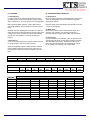
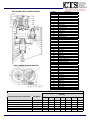
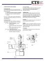
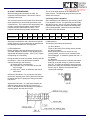
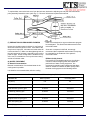
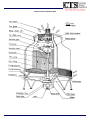
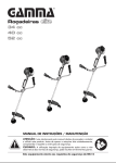
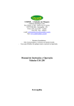
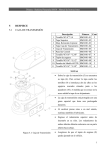
Operating
Instructions and
Service Manual
T-2 Model Cooling Towers
MEMBER
196 Lower Cherry Street
Macon, GA 31201
800-752-1905
478-755-1905
800-203-4925 FAX
478-755-8304 FAX
www.coolingtowersystems.com
[email protected]
Preface
Adequate knowledge of cooling tower maintenance and
control is necessary for optimum, safe performance over time.
In this manual, equipment construction, function, operation
and checking procedures will be described as follows:
(b) T-270 – T-3000 (refer to figure 2): The whole body
is made of aluminum alloy and is fitted with sealed
type bearings to take thrust and radial loads and to
ensure that the sprinkler head revolves smoothly.
(1) TOWER CONSTRUCTION
1.1 Type
CTS incorporates an induced-draft counter-flow design with
an axial flow fan mounted on top of the tower to draft air out.
The low internal pressure loss and circular-shaped design
ensure optimum efficiency and space economy.
1.2 Casing
The F.R.P. (fiberglass reinforced polyester) is composed of
fiberglass mat laminated from unsaturated polyester resin.
The high structural strength of the material protects the unit
against impact and cracking. Gel coat is then applied to form
a smooth surface.
1.3 Water Basin
Also made of F.R.P. material. The circular-shaped basin with
a cylindrical suction sump (ST200-1000) keeps cavitation of
the pump to a minimum. A drain connection is provided for
removal of accumulated dirt from the basin.
1.4 Tower Support Framework
(a) T-25 – T-2175: The F.R.P. base legs are incorporated
with the water basin in a single unit to withstand wind
pressure and vibration.
(b) T-2200 – T-3000: Provided with hot-dip galvanized steel
to resist corrosion and rust.
1.5 Motor Support Framework
Made of hot-dip galvanized steel to resist corrosion and rust.
1.6 Air Inlet Louver
The P.V.C. plastic mesh is fitted on the air inlet to prevent
foreign material from falling into the basin of water splashing
out of the basin.
1.7 Filling
Made of rigid polyvinyl chloride sheet which is embossed and
corrugated in a honeycomb configuration. It provides
maximum air-to-water contact for highest thermal efficiency.
1.8 Sprinkler Device
Consists of a set of sprinkler pipes and one sprinkler head
that is mounted on top of the stand pipe on the cooling tower.
The sprinkler is rotated by the pressure of circulating water.
There are numerous holes in the sprinkler pipe to allow the
water to jet out as the pump impacts rotation.
The speed can be controlled by adjusting the sprinkling angle
in accordance with the water flow rate. There are two types
of sprinkler heads.
(a) T-25 – T-260 (refer to figure 1): The outer casing is
made of nylon material; the sliding part is lubricated
by the water.
www.coolingtowersystems.com
-2-
1.9 Fan Blade
The cooling tower blades move large volumes of air quietly
and efficiently.
(a) T-25 – T-230: Made of reinforced plastic material,
the blades are coupled to the fan hub by bolts and
paste.
(b) T-240: Made of aluminum alloy, the blades are
freely adjustable by the pitch angle scale of the fan
hub.
(2) PREPARATIONS FOR STARTING
2.1
Open the drain at the bottom of the water basin and wash
dust and dirt away while scrubbing the water basin with a
brush.
2.2 Trial Circulation Wafer
Fill water in the water basin to the level where the discharge
from the ball tap stops. Slowly rotate the sprinkler by hand to
check whether it is free. Start the circulating pump, and after
washing the interior of the tower and the water pipes
thoroughly, refill the circulating water.
2.3 Checking
After the circulation test, check if there is any dirt or foreign
matter sticking to the interior of the tower or the outlets of the
sprinkling pipes. Check to see if the speed reducer belt has
been adjusted correctly.
After confirming that that the fan revolves smoothly by turning
it by hand, check the state of the gap between the tip of the
blades and the tower casing. Measure the supplied voltage
and make sure that the power supply is in the regulated type.
Revolve the fan for a short time and make sure that air is
blown upward. Revolve the fan two or three hours to see if
any vibrations or abnormal sounds are generated.
Slowly move the float of the ball tap up and down and make
sure the discharge and control system of water is accurate.
In case the tower has been left idle for a long time, check the
following points and make sure that nothing is wrong.
Confirm the insulation of the motor with a megger (see that it
is 1MΩ or above using a 500V megger).
See that no loose nuts are found at various important
junctions such as the tightened places of fan driving motor
and the junctions between the supporting base and the tower
casing. Turn the sprinkler with hand and see if it operates
smoothly.
40 Years of Manufacturing Experience
(3) STARTING
(4) CAUTIONS DURING OPERATION
3.1 Pump Driving
In order to make the circulating water fill every part of the
circulation system, revolve the circulation pump for a short
while, to drain the air out of the piping of the circulating water.
4.1 Performance
Since the cooling performance will be affected by the volume
of the circulating water, be sure to maintain the regulation
water flow at all times.
Before entering steady operation, confirm again that the
water basin is filled to the specified level, and then start the
pump.
Keep the interior of the tower always clean and take care that
no scale or moss grows.
Gradually open the adjusting valve and adjust it so that the
water will reach the volume specified on the name plate of the
cooling tower. When circulation of water becomes steady,
check to see if the sprinkler is revolving smoothly and
properly.
3.2 Fan Driving
Clean up the surroundings of the tower and make sure that
no foreign matter is near the air inlet and outlet.
4.2 Water Level
When the level of the water in the water basn drops, air is
sucked in and “cavitation” may develop; therefore, it is
necessary to keep the water at the proper level at all times.
4.3 Functioning
Pay close attention to the vibration, noise, temperature of the
cooling water and electric current during operation and make
sure that nothing goes wrong. Vibrations or noises come
mainly from the moving parts in the speed reducer and the
fan, be careful not to overlook even a slight defect.
When the equipment goes into steady operation, measure
phase voltages and phase currents to see if the motor is
operating at the rated current range indicated on the name
plate.
T-2
RPM
3
12-17
T-2 Model No:
LSU Model No:
Item No:
1
2
3
4
5
6
7
8
9
10
11
310
-040-
Revolution of the Sprinkler
40-60
80-250
5-8
5-7
5-30
7-10
1520
-050-
Description
Cap
Circlip
Bearing
Bearing Housing
Center Pole
Bearing
Oil Seal
Spring Washer
Nut
Head
Body
2540
-065-
LSH-100
Sprinkler Head
507060
100
-080-100-
125175
-125-
Specifications
LSH-125
LSH-150
300-350
3.5-5
200250
-150-
400-700
2.5-4
300400
-200-
800-3000
2-3
500700
-250-
8001000
-300-
LSH-200
LSH-250
LSH-300
6301Z
6302Z
6302Z
6303Z
6304Z
6405
6002Z
6003Z
6003Z
6004Z
6005Z
6006Z
www.coolingtowersystems.com
-3-
40 Years of Manufacturing Experience
(D) V-Belts
Maintain belt adjustment as decribed above. This drive
uses high quality special V-belts. The V-belts are
designed to operate 5,000 to 10,000 hours. If slipping
or belt abrasion becomes evident after operating over
5,000 hours then replace the belt sets. If after 5,000
hours, excessive adjustments of belt tension are
required due to belt stretch, the belts have reached
V-Belt Speed
Reducer
Model No.
T-2 Model
Fan Speed
R.P.M.
LBM-055C
225 & 250
398
LBM-075
300 & 350
398
LBM-110
400 & 500
342
LBM-150
600 & 700
282
LBM-220
800 & 1000
265
the end of their life and should be replaced with belts
as recommended in the V-belt table. Since V-belts are
not widely available, please contact our nearest
distributor for replacement. Belts must always be
replaced in matched sets: i.e., both upper and
lower sets must be replaced simultaneously.
Hence, one faulty belt requires the replacement of up to
10 belts.
V-Belt Table (I)
Belts No.
V-Belt Model
No.
2-11MS-800
3-11MS-800
2-11MS-800
3-11MS-800
2-11MS-1400
3-11MS-1400
2-11MS-1400
3-11MS-1400
2-11MS-1550
3-11MS-1550
Belts No.
of Upper
Pulley
1
1
1
1
1
Belts No.
of Lower
Pulley
1
2
1
1
1
2
1
V-Belt Table (II)
Belts No.
V-Belt Model
No.
Belts No.
of Upper
Pulley
Belts No.
of Lower
Pulley
Belts No.
Total
Belts No.
Total
1
1
2
1
1
1
2
1
2
2
V-Belt Speed
Reducer
Model No.
T-2 Model
Fan Speed
R.P.M.
LBM-055C
225 & 250
398
11M-800
2
3
5
LBM-075
300 & 350
398
11M-800
3
4
7
LBM-110
400 & 500
342
11M-1400
2
3
5
LBM-150
600 & 700
282
11M-1400
2
5
7
LBM-220
800 & 1000
265
11M-1550
3
7
10
www.coolingtowersystems.com
-4-
40 Years of Manufacturing Experience
Item No.
1
2
3
4
5
6
7
8
9
10
11
12
13
14
15
16
17
18
19
20
21
22
23
24
25
26
27
28
29
30
31
32
33
34
35
36
37
38
39
40
41
42
43
44
45
46
47
48
49
50
51
52
MOTOR AND V-BELT SPEED REDUCER
V-BELT SPEED REDUCER SECTION
Description
Support Pin
Adjusting Lever
Adjusting Gauge
Adjusting Spring
Washer
Adjusting Bolt
Sight Glass
Cooling Fan
Lifting Ring
Pulley No. 1
V-Belts (Upper)
Key A
Pulley No. 4
Key D
Circlip D
V-Belts (Lower)
Grease Nipple
Housing Cover No. 1
Bearing D
Oil Seal D
Fan Shaft
Housing (Fan Shaft)
Bearing E
Bearing G
Housing Cover No. 2
Oil Seal E
Key E
Circlip B
Key B
Belt Cover
Pulley No. 2
Interm. Shaft Housing
Bearing B
Intermediate Shaft
Bearing C
(Interm. S.) Housing Cover
Oil Seal C
Pulley No. 3
Circlip C
Key C
Fan Shaft Nut
Belt Case
Bearing F
Motor Shaft
Terminal Box
Stator Frame
Bearing A
Set Screw 1
Stator Coil
Stator Core
Rotor Core
Set Screw 2
V-BELT SPEED REDUCER BEARING TABLE
Bearing
V-Belt Speed Reducer Model No.
LBM-055C
LBM-075
LBM-110
LBM-150
LBM-220
LBM-300
LBC Model
225 & 250
300 & 350
400 & 500
600 & 700
800 & 1000
1250 & 1500
www.coolingtowersystems.com
F
A
B
C
D
E
G
6306zz
6306zz
6308zz
6308zz
6309zz
6312zz
6308zz
6308zz
6309zz
6309zz
6311zz
6312zz
6207z
6208z
6208z
6209z
6213z
6213z
6309z
6310z
6310z
6313z
6317z
6317z
6211z
6211z
6213z
NJ313
NJ317
NJ317
6012z
6012z
6213z
NJ215
NJ217
NJ217
51112
51112
51113
51115
51117
51117
-5-
40 Years of Manufacturing Experience
(5) MAINTENANCE AND CONTROL
5.1 Sprinkler Pipe
The sprinkler pipe must be clean without blockage. If
there is some foreign material retarded in the pipe, take
the following steps:
(A) Loosen the set screw or lock nut on sprinkler
device, then remove sprinkler pipe and clean.
(B) Align the dot mark on sprinkler head and
reinstall.
For T-25 – T-215 models, they are fitted with type A
and B pipe (the hole pitch is different to assure even
water distribution.
5.2 Sprinkler Head
The sprinkler head rotation will slow or even stop if
scale is stuck to it. In this case, check it as follows:
(A) T-25 – T-260 (refer to Fig. 1)
a. remove set screw cap on top of
sprinkler head.
b. loosen nut and washer, then take head
off.
c. clean it with fresh water and check if
any component is worn out.
(B) T-270 – T-3000 (refer to Fig. 2)
a. remove the cap and take circlip off.
b. pull the rotary part off the fixing part
and check: replace if necessary.
www.coolingtowersystems.com
-6-
5.3 Tower Casing
No coating is needed for the tower casing as it is made
of F.R.P. If it becomes soiled, wipe it with soap or a
water-soaked piece of cloth and then wash it
thoroughly with water.
5.4 Water Basin
As dust and dirt are liable to get into the water basin,
open the drain at the bottom of the drop-in tank from
time to time and wash it clean. This applies also to the
water basin in particular, as sediments are liable to
accumulate near the outlet, so keep the tank clean so
that the strainer mesh will not be clogged.
5.5 Filling
No special care is needed if the control of the quality of
water is adequate during operation.
5.6 Fan
Watch the surface of the blades carefully to see that no
damage develops and make sure that proper space is
maintained between the internal wall of tower casing
and the tip of blades.
5.7 Coating
It is desirable to periodically recoat the metal parts as
they are subject to rusting.
40 Years of Manufacturing Experience
(6) V-BELT SPEED REDUCER
With increasing public awareness of noise, our
engineers have developed a V-belt drive to reduce
operating noise levels.
The life of the belts depends on the maintenance of
proper tension. The adjusting gauge is factory set and
should not be altered.
6.2 Testing of Drive Operation
After checking the belt adjustment, spin the fan by hand
to see whether it is free. If it spins freely and smoothly,
start the fan motor. After 2 to 4 hours operation, check
amperage and voltage and compare the readings with
motor nameplate data. Check the motor temperature
and check noise and vibration.
This new drive produces much lower noise levels than
those obtained from conventional gear drives of the
equivalent size. The V-belt is a wide angle (60°C) and
is made of a special polyurethane compound with
polyester tension cords (tensile member). Very
compact V-belt drives are possible with this belt.
T-2 Model No.
5-8
10-15
20-30
40-50
60-80
100-125
150-200
225-350
400-500
600-700
800-1000
LSF Model No.
-050-
-070-
-080-
-100-
-120-
-150-
-180-
-240-
-300-
-340-
-360-
With proper maintenance, the V-belt drive will operate
reliably; however, proper maintenance is essential and
the following instructions are very important.
6.1 Belt Adjustment
Before operation, open the adjustment access cover
and check whether the washer on the adjusting bolt is
aligned with the adjusting gauge. (Ref. Fig. A) Tighten
the adjusting nut if necessary.
During operation, the belt may stretch, allowing belt slip
and abrasion. Hence, the belt tension should be
checked according to the following:
(A) 50 hours after commissioning.
(B) Thereafter, carry out 3 checks, each at 100
hour intervals.
th
(C) After the 4 check, at 350 hours, then check
each month.
6.3 Maintenance
The following work should be performed.
(A) Drive Section
Clean out the inside of the driving section annually.
(B) Motor Insulation
Before putting the tower into service in each
cooling season, check the motor insulation with a
500 Volt Megger. A resistance greater than 1MΩ is
acceptable.
(C) Bearings
Although it is unneccessary to lubricate the sealed
bearings, an annual change of grease will extend
their life. To repack the bearings, remove the seal
plates with a sharp tool inserted as indicated by the
arrow in Fig. B. Replace the seal plates after
replacing the bearings.
Off-Season Shut Down – For a long-time shut down,
slacken the adjusting nut 4-5mm to prevent bolt stretch.
Re-adjust belts prior to putting the cooling tower back
into service.
Adjustment Precaution – If a gap exists between the
adjusting gauge and the washer, the belts are too
slack. If the washer and the adjusting nut overlap the
adjusting gauge, the belts are too tight.
www.coolingtowersystems.com
-7-
40 Years of Manufacturing Experience
To replace belts, remove the belt cover from the belt case, slacken the adjusting nut and push the intermediate
pulley assembly toward the motor (refer Fig. C). Remove old belts and replace with new sets.
(7) PRECAUTIONS IN PROLONGED IDLENESS
tower is commissioned, a reguar maintenance program
be investigated. This should included treatment of the
recirculated water.
Unless the circulation water is drained, it may freeze in
winter and cause the pipes to crack. If the drain of the
drop-in tan is kept open, rain-water and snow water will
not accumulate in it. Make sure that tightening bolts on
the various parts of the tower, especially on the moving
parts are tight. As the cooling tower is installed on top
of the roof, it is desirable to cover up the tower casing
and the air exhaust outlet.
As we are not experts in this field, we strongly
recommend that a reputable water treatment company
be consulted for the treatment of the system’s
recirculated water.
B.Water Quality Control
Poor quality of recirculated water due to air pollution,
corrosion, scale and algae growth will impede the
performance of water cooling equipment. We
recommend a periodic water analysis and that blowdown be initiated to maintain the water quality within
the water cooling system to the following criteria:
(8) WATER TREATMENT
A. Bacterial Contamination
Bacterial contamination of recirculated water in the
cooling tower is possible.
It is therefore recommended that, after the cooling
Permissible Value of Water Analysis (JCI Code)
PARAMETER
Make-up water
Circulating water
6-8
6-8
Electric conductivity (µv/cm)
200 below
500 below
Total hardness (CaCO3) ppm
50 below
200 below
M alkalinity (CaCO3) ppm
50 below
100 below
Chlorine ion (CI) ppm
50 below
200 below
Sulphuric acid ion (SO4) ppm
50 below
200 below
Silicic acid (SiO2) ppm
30 below
50 below
Ferric (Fe) ppm
0.3 below
1.0 below
PH (25° C)
www.coolingtowersystems.com
-8-
40 Years of Manufacturing Experience
Trouble Analysis Table
Trouble
Causes
Counter-Measures
1.
Excess or inadequate cooling water flow.
1.
Adjust to the specified flow.
2.
Irregular flow of air.
2.
Improve ventilation.
Rise in cooling water
3.
Recirculation of air exhausted from tower.
3.
Same as above or install baffles.
temperature
4.
Irregular operation of sprinkler pipes.
4.
Remove dust and scale.
5.
Improper flow of air.
5.
Adjust the angle of fan blades.
6.
Blocking of the filling.
6.
Clean the blocked areas.
1.
Blocking of the sprinkler pipe holes.
1.
See section for maintenance and
2.
Blocking of strainer mesh.
3.
Drop in the water level of water basin.
4.
Improper selection of water circulating
Drop in the volume of
cooling water
adjustment.
Excessive current draw
Water carry over
Remove strainer and clean.
3.
Adjust float valve.
4.
pump.
Noise and vibration
2.
Replace the pump with one matching
planned volume of water.
1.
Fan blade tips touching fan stack.
1.
Adjust the fan mounting.
2.
Improper mounting of fan blades.
2.
Correct the blade angle settings.
3.
Loose belts.
3.
Tighten loose bolts.
4.
Shortage of speed reducer oil.
4.
Supply oil up to the level specified.
1.
Drop in voltage.
1.
Check supply voltage. Notify power
2.
Irregularities in the angles of the fan blades.
3.
Overload through excess airflow.
1.
Irregular operation of sprinkler pipes.
2.
Blocking of the filling.
3.
Defective eliminator.
4.
Too much circulating water.
company if necessary.
2.
Adjust fan blade angles.
3.
Adjust fan blade angles.
1.
Adjust the angle of the sprinkler pipes
in the sprinkler head.
2.
Eliminate blockage at the upper edge
of the filling.
3.
Renew the eliminator.
4.
Adjust the water flow by means of the
valve.
www.coolingtowersystems.com
-9-
40 Years of Manufacturing Experience
Construction & Installation Data
www.coolingtowersystems.com
- 10 -
40 Years of Manufacturing Experience
Guarantee
COOLING TOWER SYSTEMS, INC. GUARANTEE IS AS FOLLOWS:
DOMESTIC – WITHIN THE CONTINENTAL UNITED STATES:
A.
B.
C.
Ten Years on FRP, (fiberglass) casing, and cold water basins.
Two (2) years on all PVD fillings.
One (1) year on all fan motors, major drive components, and all internal moving parts.
NOTE: An Extended Manufacturer’s Warranty is available, for an additional nominal fee, and is set into
place as part of the original purchase.
INTERNATIONAL ORDERS/WARRANTY:
A.
B.
C.
Eighteen (18) months, after shipping date.
One (1) year, after initial start-up of Cooling Tower.
*Note – only “A” or “B” is applicable, which ever comes first.
Cooling Tower Systems, Inc. wishes to Thank You for your patronage and we look forward to adding
you as a satisfied customer!
www.coolingtowersystems.com
- 11 -
40 Years of Manufacturing Experience