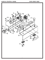
1
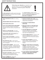
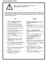
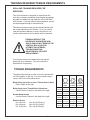
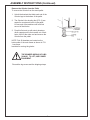
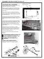
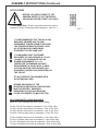
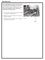
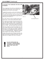
ACCU-660
MANUAL
BEDKNIFE GRINDER
ASSEMBLY
AND
SERVICE
MANUAL
WARNING
You must thoroughly read and understand this
manual before assembling or maintaining the
equipment, paying particular attention to the
Warning & Safety instructions.
1
6607954 (6-03)
SAFETY INSTRUCTIONS
Safety Awareness Symbols are inserted into this
manual to alert you to possible Safety Hazards.
Whenever you see these symbols, follow their
instructions.
The Warning Symbol identifies special instructions
or procedures which, if not strictly observed, could
result in personal injury.
1. KEEP GUARDS IN PLACE and in working
order.
The Caution Symbol identifies special
instructions or procedures which, if not correctly
followed, could result in damage to or
destruction of equipment.
13. MAINTAIN GRINDER WITH CARE. Follow
instructions in Service Manual for lubrication
and preventive maintenance.
2. REMOVE WRENCHES AND OTHER TOOLS.
3. KEEP WORK AREA CLEAN.
4. DON'T USE IN DANGEROUS ENVIRONMENT.
Don't use Grinder in damp or wet locations.
Machine is for indoor use only. Keep work area
well lit.
5. KEEP ALL VISITORS AWAY. All visitors
should be kept a safe distance from work area.
6. MAKE WORK AREA CHILD-PROOF with
padlocks or master switches.
7. DON'T FORCE THE GRINDER. It will do the
job better and safer if used as specified in this
manual.
8. USE THE RIGHT TOOL. Don't force the
Grinder or an attachment to do a job for which it
was not designed.
9. WEAR PROPER APPAREL. Wear no loose
clothing, gloves, neckties, or jewelry which may
get caught in moving parts. Nonslip footwear is
recommended. Wear protective hair covering
to contain long hair.
14. DISCONNECT POWER BEFORE
SERVICING.
15. REDUCE THE RISK OF UNINTENTIONAL
STARTING. Make sure the switch is OFF
before plugging in the Grinder.
16. USE RECOMMENDED ACCESSORIES.
Consult the manual for recommended
accessories. Using improper accessories
may cause risk of personal injury.
17. CHECK DAMAGED PARTS. A guard or other
part that is damaged or will not perform its
intended function should be properly repaired
or replaced.
18. KNOW YOUR EQUIPMENT. Read this
manual carefully. Learn its application and
limitations as well as specific potential
hazards.
19. KEEP ALL SAFETY DECALS CLEAN AND
LEGIBLE. If safety decals become damaged
or illegible for any reason, replace
immediately. Refer to replacement parts
illustrations in Service Manual for the proper
location and part numbers of safety decals.
10. ALWAYS USE SAFETY GLASSES.
11. SECURE YOUR WORK. Make certain that the
bedknife is securely fastened with the
electromagnets provided before operating.
20. DO NOT OPERATE THE GRINDER WHEN
UNDER THE INFLUENCE OF DRUGS,
ALCOHOL, OR MEDICATION
12. DON'T OVERREACH. Keep proper
footing and balance at all times.
2
SAFETY INSTRUCTIONS
IMPROPER USE OF GRINDING WHEEL MAY CAUSE
BREAKAGE AND SERIOUS INJURY.
Grinding is a safe operation if the few basic rules listed below are followed. These rules are
based on material contained in the ANSI B7.1 Safety Code for "Use, Care and Protection of
Abrasive Wheels". For your safety, we suggest you benefit from the experience of others and
carefully follow these rules.
DO
DON'T
1. DO always HANDLE AND STORE
wheels in a CAREFUL manner.
1. DON'T use a cracked wheel or one that
HAS BEEN DROPPED or has become
damaged.
2. DO VISUALLY INSPECT all wheels
before mounting for possible damage.
2. DON'T FORCE a wheel onto the machine
OR ALTER the size of the mounting hole.
If wheel won't fit the machine, get one that
will.
3. DO CHECK MACHINE SPEED against
the established maximum safe operating
speed marked on wheel.
3. DON'T ever EXCEED MAXIMUM
OPERATING SPEED established for the
wheel.
4. DO CHECK MOUNTING FLANGES for
equal and correct diameter.
5. DO USE MOUNTING BLOTTERS when
supplied with wheels.
4. DON'T use mounting flanges on which the
bearing surfaces ARE NOT CLEAN,
FLAT AND FREE OF BURRS.
6. DO be sure WORK REST is properly
adjusted.
5. DON'T TIGHTEN the mounting nut
EXCESSIVELY.
7. DO always USE A SAFETY GUARD
COVERING at least one-half of the
grinding wheel.
6. DON'T grind on the SIDE OF THE WHEEL
(see Safety Code B7.2 for exception).
8. DO allow NEWLY MOUNTED WHEELS to
run at operating speed, with guard in
place, for at least one minute before
grinding.
7. DON'T start the machine until the WHEEL
GUARD IS IN PLACE.
9. DO always WEAR SAFETY GLASSES or
some type of eye protection when
grinding.
9. DON'T STAND DIRECTLY IN FRONT of a
grinding wheel whenever a grinder is
started.
10. DO TURN OFF COOLANT before
stopping to avoid creating an
out-of balance condition.
10. DON'T FORCE GRINDING so that motor
slows noticeably or work gets hot.
3
8. DON'T JAM work into the wheel.
SAFETY INSTRUCTIONS/SPECIFICATIONS
This machine is intended for grinding the bedknife from a reel mowing
unit ONLY. Any use other than this may cause personal injury and void
the warranty.
To assure the quality and safety of your machine and to maintain the
warranty, you MUST use original equipment manufactures replacement
parts and have any repair work done by a qualified professional.
ALL operators of this equipment must be thoroughly trained BEFORE
operating the equipment.
Do not use compressed air to clean grinding dust from the machine.
This dust can cause personal injury as well as damage to the grinder.
This machine is intended for indoor use only. Do not use a power washer
to clean the machine.
CONTENTS
Safety Instructions/Specifications ................................................................ Page 2 - 4
Training Required/Torque Requirements ..................................................... Page 5
Assembly...................................................................................................... Page 6 - 13
Maintenance ................................................................................................. Page 14 - 15
Adjustments ................................................................................................. Page 16 - 20
Troubleshooting ........................................................................................... Page 21 - 24
Parts Lists/Exploded Views .......................................................................... Page 25 - 43
SPECIFICATIONS
Electrical Requirements ............................................................ 115V 50/60 Hz, 15-amp circuit
Net Weight ....................................................................................................... 670 lbs [304 kg]
Shipping Weight ............................................................................................... 700 lbs [318 kg]
Maximum Grinding Length ................................................................................32 in. [813 mm]
Sound Level..................................................................................................... Less than 75 Dba
4
TRAINING REQUIRED/TORQUE REQUIREMENTS
SKILL AND TRAINING REQUIRED FOR
SERVICING
This Service Manual is designed for technicians who
have the necessary mechanical and electrical knowledge
and skills to reliably test and repair the ACCU-660 Bedknife Grinder. For those without that background, service
can be arranged through a local distributor.
This Manual presumes that you are already familiar with
the normal operation of the Grinder. If not, you should
read the Operators Manual, or do the servicing in conjunction with someone who is familiar with its operation.
PERSONS WITHOUT THE
NECESSARY KNOWLEDGE AND
SKILLS SHOULD NOT REMOVE THE
CONTROL BOX COVER OR
ATTEMPT ANY INTERNAL
TROUBLESHOOTING,
ADJUSTMENTS, OR PARTS
REPLACEMENT!
If you have questions not answered in this manual,
please call your distributor. They will contact the
manufacturer if necessary.
TORQUE REQUIREMENTS
Throughout this manual we refer to torque requirements
as "firmly tighten" or the like. For more specific torque
values, refer to the information below.
GRADE 2
Bolts Going into a Nut, or Into a Thread Hole in Steel.
Refer to table at the right.
Bolts Going into a Thread Hole in Aluminum.
Use the Grade 2 values in the table at the right.
Socket-Head Screws
Use the Grade 8 values in the table at the right.
Machine Screw
No. 6 Screws:
No. 8 Screws:
No. 10 Screws:
11in.-lbs [0.125 kg-m]
20 in.-lbs [0.23 kg-m]
32 in.-lbs [0.37kg-m]
5
GRADE 5 GRADE 8
SMOOTH
HEAD
3 MARKS
on HEAD
6 MARKS
on HEAD
1/4 In.
thread
6 ft-lbs
(0.8 kg-m)
9 ft-lbs
(1.25 kg-m)
13 ft-lbs
(1.8 kg-m)
5/16 In.
thread
11 ft-lbs
(1.5 kg-m)
18 ft-lbs
(2.5 kg-m)
28 ft-lbs
(3.9 kg-m)
3/8 In.
thread
19 ft-lbs
(2.6 kg-m)
31 ft-lbs
(4.3 kg-m)
46 ft-lbs
(6.4 kg-m)
7/16 In.
thread
30 ft-lbs
(4.1 kg-m)
50 ft-lbs
(6.9 kg-m)
75 ft-lbs
(10.4 kg-m)
1/2 In.
thread
45 ft-lbs
(6.2 kg-m)
75 ft-lbs
115 ft-lbs
(10.4 kg-m) (15.9 kg-m)
ASSEMBLY INSTRUCTIONS
UNPACK THE CARTONS
NOTE: Before you install the machine, read the
following assembly procedure completely. Then study
"Getting to Know Your Bedknife Grinder" in the
Operators Manual.
Use care when unpacking. Double-check the packing
cartons for any miscellaneous items before discarding.
Inspect all items for shipping damage as they are
removed from the shipping containers. If you find any
damage, notify the carrier's claims agent and do not
proceed further until the damage has been inspected by
the agent. Refer also to the "Shipping and Receiving
Instructions" packed with the unit.
FIG. 1
Remove the shipping strap that secures the carriage to
the left end of the machine during shipment.
Fork Lift Brackets
INSTALLATION OF UPPER GRINDING HEAD
ASSEMBLY
To remove the load from the large V rollers during
shipping, the upper grinding head assembly is shipped
on the crate base.
To install the upper grinding head assembly, remove the
two feed screw guide screws that are
temporarily installed in the carriage and set aside.
Remove the manual traversing handle and set aside.
Remove the double wire clip and screw and set aside.
Cut the plastic strap that holds the upper grinding head
assembly to the crate base. Remove the blue die spring
from the infeed handwheel where it has been taped and
install the spring between the carriage slide and the
small vee roller arm setscrew. Loosen the setscrew so it
is flush to the outside of the arm. Lift the upper grinding
head assembly and install the small vee rollers onto the
V cut on the carriage.
Adjust the preload tension on the small vee roller arm
per the procedure on page 20.
Install the two feed infeed guide screws. Install the
manual traversing handle. Install the motor cord and
coolant hose through the double wire clip, leaving
enough slack for motor infeed movement and install to
the carriage. Cable tie the motor cord and coolant hose
to the cable tie mount in the center of the grinder under
the coolant tank lip. Do not pull the cable tie tight or you
will restrict coolant flow.
6
ASSEMBLY INSTRUCTIONS (Continued)
Remove the Grinder from the Pallet
To remove the Grinder from the wood pallet:
1. Unbolt the brackets that hold each end of the
Grinder legs to the bottom of the pallet.
2. The Grinder's four leveling feet (FIG. 2) are
seated in countersunk holes in the pallet.
Lift one end of the machine until both feet
are out of their holes.
3. Prop this first end up with sturdy boards or
other supports so the feet remain out of their
holes, then lift the other end and remove the
Grinder from the pallet.
FIG. 2
NOTE: Fork lift brackets are located on the
bottom side of the main frame as shown in FIG.
1 use these
brackets for moving the grinder.
THE GRINDER WEIGHS 670 LBS
[304KG]. TO LIFT, USE POWER
EQUIPMENT.
Discard the leg screws and the shipping straps.
7
ASSEMBLY INSTRUCTIONS (Continued)
Machine can be located
tight to the wall
Wall
LOCATE AND LEVEL THE GRINDER
Set the Grinder on a level concrete floor, on a
single uncracked slab of concrete.
If the unit must be located near a wall, allow adequate space for operating and servicing. Refer to
FIG. 3 for recommended and alternate locations
near a wall.
Place a level on the front carriage rail near the
center of the machine and check the level from left
to right. See FIG. 4A. Adjust the leveling feet until
the machine is level.
Place the level across the front and rear carriage
rails near the left end of the machine. See FIG. 4B.
Adjust the two leveling feet on the left end until
level.
10" [25.4cm]
Wall, if necessary
FIG. 3
Place the level across the front and rear carriage
rails near the right end of the carriage bed. Level
the right end in the same way as the left end. For
grinding accuracy, the two ends must have the
identical level within +/-.01" [.25 mm] so the frame
is not twisted.
Recheck the level in both directions. When
satisfactory, tighten the hex jam nuts on the leveling feet securely against the nuts welded to the
bottom of the base. See FIG. 2. Don't turn the
leveling feet when tightening.
FIG. 4A
Again recheck the level after the nuts are firmly
tightened.
FOR GRINDING ACCURACY, THE MACHINE
DOES NOT HAVE TO BE PERFECTLY
LEVEL. HOWEVER, IT IS CRITICAL THAT
FRONT-TO-BACK LEVELING BE
IDENTICAL AT BOTH ENDS OF THE
MACHINE.
INSTALL THE SPINNING HANDLE
Install the spinning handle on the horizontal
handwheels. See FIG. 5. Handle parts are
FIG. 4B
FIG. 6
FIG. 5
8
ASSEMBLY INSTRUCTIONS (Continued)
APPLY POWER
BEFORE YOU APPLY POWER TO THE
GRINDER, REFER TO THE "IMPORTANT
GROUNDING INSTRUCTIONS" ON PAGE 9.
115 Volt Model Only. Plug the control box power cord into a
standard 115V AC 15-amp grounded receptacle. See FIG. 7.
IT IS RECOMMENDED THAT THIS ACCU-660
BEDKNIFE GRINDER HAS ITS OWN
PERMANENT POWER CONNECTION FROM
THE POWER DISTRIBUTION PANEL, WITH
NO OTHER MAJOR POWER DRAW
EQUIPMENT ON THE SAME LINE.
IT IS REQUIRED THAT THE POWER
DELIVERED TO THIS GRINDER IS 115 VAC 15 AMPS. THE TOLERANCE ON THIS
POWER REQUIREMENT IS +/- 5%.
THEREFORE THE MINIMUM VOLTAGE
REQUIREMENT IS 109VAC WITH 15 AMPS.
VOLTAGE MUST BE CHECKED WITH ALL
EQUIPMENT UNDER LOAD (OPERATING) ON
THE CIRCUIT.
DO NOT OPERATE THIS GRINDER WITH
AN EXTENSION CORD.
PROPER GROUNDING OF THE
RECEPTACLE GROUND IN YOUR BUILDING
MUST BE VERIFIED. IMPROPER
GROUNDING IN YOUR BUILDING MAY
CAUSE THE GRINDER TO MALFUNCTION.
FOR 15 AMP RATED LARGE MACHINES
Below is a list of required wire size in your building.
For 0 to 30 Feet from panel to receptacle = Use 14 Ga. Wire.
For 30 to 50 Feet from panel to receptacle = Use 12 Ga. Wire.
For 50 to 80 Feet from panel to receptacle = Use 10 Ga. Wire.
For 80 to 140 Feet from panel to receptacle = Use 8 Ga. Wire.
For 0 to 9 Meters from panel to receptacle = Use 2.5mm Wire.
For 9 to 15 Meters from panel to receptacle = Use 4.0mm Wire.
For 15 to 24 Meters from panel to receptacle = Use 6.0mm Wire.
For 24 to 42 Meters from panel to receptacle = Use 10.0mm Wire.
9
FIG. 7
FOR 220 V 50 or 60Hz applications Product No.
6600951 should be ordered.
6600951 has a 2 KVA step down transformer
from 220V 50-60 Hz input power to 115V 50-60
Hz machine power.
The wiring diagram is shown in FIG. 7A.
The power cord has no connector. A connector
which is appropriate for your locality and 220 volt,
8 amp application should be installed.
Use only a qualified electrician to
complete the installation.
FIG. 7A
IMPORTANT GROUNDING INSTRUCTIONS
In case of a malfunction of breakdown, grounding reduces the risk of electrical shock by providing a path
of least resistance for electrical current.
This Grinder has an electrical cord with an equipment grounding conductor and a grounding plug. The
plug must be plugged into a matching outlet that is properly installed and grounded according to all local
or other appropriate electrical codes and ordinances.
Before plugging in the Grinder, make sure it will be connected to a supply circuit protected by a properlysized circuit breaker or fuse.
Never modify the plug provided with the machine--if it won't fit the outlet, have a proper outlet and circuit
installed by a qualified electrician.
ALWAYS PROVIDE A PROPER ELECTRICAL GROUND FOR
YOUR MACHINE. AN IMPROPER CONNECTION CAN CAUSE A
DANGEROUS ELECTRICAL SHOCK. IF YOU ARE UNSURE OF
THE PROPER ELECTRICAL GROUNDING PROCEDURE,
CONTACT A QUALIFIED ELECTRICIAN.
10
This Page Left Intentionally Blank for Note Taking Purposes
11
ASSEMBLY INSTRUCTIONS (Cont.)
INSTALL THE COOLANT
ALWAYS READ THE MATERIAL
SAFETY DATA SHEET (MSDS) FOR
THE COOLANT YOU ARE USING.
BELOW ARE WARNINGS THAT
APPLY TO MOST COOLANTS.
AVOID CONTACT OF COOLANT WITH
EYES: IT WILL CAUSE EYE
IRRITATION. WEAR FACE SHIELD
OR GOGGLES WHEN HANDLING
CONCENTRATE. IN CASE OF
CONTACT, FLUSH EYES WITH
WATER FOR 15 MINUTES AND
CONTACT A PHYSICIAN.
AVOID BREATHING MISTS. PROVIDE
LOCAL VENTILATION. KEEP
CONCENTRATED BOTTLE CLOSED
WHEN NOT IN USE.
CONTINUED CONTACT OF
CONCENTRATE ON SKIN MAY CAUSE
IRRITATION. WASH WITH SOAP AND
WATER AFTER CONTACT.
DO NOT TAKE INTERNALLY. IF
INGESTED, CONSULT PHYSICIAN
AND DO NOT INDUCE VOMITING.
(HAZARD POTENTIAL APPLIES TO
CONCENTRATE, AND IS LESS AT
NORMAL USE DILUTION.)
Mixing the Coolant
Mix Part No. 3708620 Coolant in a separate container,
at a ratio of 50 parts water to 1 part concentrate. Refer
also to the label on the Coolant container. If the coolant
tray is empty, this will take about 8gallons of water and
1.3 pint of concentrate [30 liters of water, and 0.6 liter of
concentrate]. Fill with coolant until the coolant level is
.25 - .50" [ 6 -12 mm] above the top of the coolant
pump.
THE COOLANT RATIO AS SPECIFIED MUST BE
USED. TO HIGH A CONCENTRATION OR
LOW A CONCENTRATION WILL CAUSE
CORROSION AND PERFORMANCE
PROBLEMS.
12
ASSEMBLY INSTRUCTIONS (Continued)
CHECK THE CARRIAGE TRAVERSE
Visually check that the grinding head will be able to traverse
to both sides of the machine without contacting any
components.
Manually move the grinding head through a complete cycle.
Watch carefully for obstructions to the head travel, and check
that the grinding motor cord and coolant hose are not
stretched.
CHECK THE GRINDING MOTOR
Close the guard door to connect the interlock. Press START.
Check that the grinding head runs properly. Be prepared to
press STOP if there is any problem. Also check that the
coolant system functions properly.
MAKE FINAL PREPARATIONS FOR OPERATION
Carefully read the operating instructions in the Operators
Manual.
First, study the pages titled "Getting to Know Your Grinder"
and "General Operating Information" for important
background explanations about the machine and about
bedknife grinding. Then, read the "Operating Instructions"
pages for step-by-step procedures on mounting the
bedknife and grinding its top and front faces.
13
MAINTENANCE
DAILY MAINTENANCE IS SPECIFIED ON PAGE 4
OF THE OPERATOR'S MANUAL, AND IS TO BE
PERFORMED BY THE OPERATOR. LISTED
BELOW ARE PERIODIC MAINTENANCE ITEMS
TO BE PERFORMED BY YOUR COMPANY'S
MAINTENANCE DEPARTMENT:
1. Clean the Traverse Rails by wiping down with WD-40
or equivalent on a weekly basis.
2. Replace the four foam rail wipers (FIG. 10) every 6
months of operation.
3. Clean the interior of the Coolant Tray as necessary
and at least every 6 months.
FIG. 10
Wiper
14
MAINTENANCE (Continued)
CLEANING AND MAINTENANCE GUIDELINES FOR POLYCARBONATE WINDOWS
Cleaning Instructions
DO NOT USE GASOLINE
Adherence to regular and proper
cleaning procedures is recommended
to preserve appearance and performance.
Washing to Minimize Scratching
Wash polycarbonate windows with a mild dish washing liquid detergent and lukewarm water, using
a clean soft sponge or a soft cloth. Rinse well with clean water. Dry thoroughly with a moist
cellulose sponge to prevent water spots. Do not scrub or use brushes on these windows.
Also, do not use butyl cellosolve in direct sunlight.
Fresh paint splashes and grease can be removed easily before drying by rubbing lightly with a
good grade of VM&P naphtha or isopropyl alcohol. Afterward, a warm final wash should be
made, using a mild dish washing liquid detergent solution and ending with a thorough rinsing
with clean water.
Minimizing Hairline Scratches
Scratches and minor abrasions can be minimized by using a mild automobile polish. Three
such products that tend to polish and fill scratches are Johnson paste Wax, Novus Plastic
Polish #1 and #2, and Mirror Glaze plastic polish (M.G. M10). It is suggested that a test be
made on a corner of the polycarbonate window with the product selected following the polish
manufacturer's
instructions.
Some Important "DON'TS"
n
n
n
DO NOT use abrasive or highly alkaline cleaners on the polycarbonate windows.
Never scrape polycarbonate windows with squeegees, razor blades or other sharp
instruments.
Benzene, gasoline, acetone or carbon tetrachloride should NEVER be used on
polycarbonate windows.
DO NOT clean polycarbonate windows in hot sun or at elevated temperatures.
Graffiti Removal
n
Butyl cellosolve, (for removal of paints, marking pen inks, lipstick, etc.)
The use of masking tape, adhesive tape or lint removal tools works well for lifting off old
weathered paints.
To remove labels, stickers, etc., the use of kerosene, VM&P naphtha or petroleum spirits
is generally effective. When the solvent will not penetrate sticker material, apply heat
(hair dryer) to soften the adhesive and promote removal.
GASOLINE SHOULD NOT BE USED!
15
ADJUSTMENT (Continued)
TO ADJUST THE CARRIAGE VEE ROLLERS
ECCENTRIC
The carriage large Vee rollers are adjusted for zero
free play with an eccentric on the single roller
attachment bolt closest to the operator.
To adjust the eccentric, position the Grinding Head
and Carriage Assembly to center it on the traverse
rail center strut assembly. Move the Grinding Head
inward with the infeed handwheel to expose the vee
roller lock nut. See FIG. 11.
FIG. 11
Put a 3/4" wrench on the hex head eccentric bolt
bottom side. Loosen the top side locknut with a
1/2" socket only enough to move the eccentric bolt.
The roller spacer washer under the carriage and
above the roller assembly must be completely flush
with no air gaps. If you have air gaps, the eccentric
bolt is to loose. With the eccentric bolt and locknut
loose only enough to move the eccentric, turn the
(3/4" wrench) eccentric bolt only enough to take the
free play out of the large vee rollers. Determine
zero free play by grasping the carriage and trying to
move it up and down firmly. Tighten the eccentric
only enough for zero free play. When correct,
retighten the top side lock nut. Make certain the roller
spacer and bracket are tightened square to the carriage with no air gaps, then verify no free play.
DO NOT OVERTIGHTEN THE
ECCENTRIC. OVERTIGHTENING
CAN OVERLOAD THE TRAVERSE
SHAFTS AND CAUSE A BAD
GRIND.
16
Vee Roller Lock Nut
ADJUSTMENTS (Continued)
TO ELIMINATE INFEED HANDWHEEL
BACKLASH
If there is backlash in the Grinder Head Infeed
handwheel (FIG. 12A), there are two adjustment
points on each to check:
1. Washers behind the handwheel:
A. Loosen (about half a turn) the setscrew
holding the handwheel to the shaft. This set
screw is accessed by removing the calibration
ring set screw and rotating the calibration ring
to access the handwheel setscrew.
B. Tighten the hex lock nut which secures the
handwheel to 100 in. lbs. [1.15 kg-m], then
back off 1/2 turn.
C. Check for .015 in. [.04mm] gap between
the wave washer and the flat washer. See FIG.
12B.Readjust the hex lock nut if necessary.
FIG. 12A
Setscrew with nylon ball
Infeed
Handwheel
Hex Nut
D. Tighten the setscrew holding the handwheel
to the shaft. Install and tighten the calibration
ring setscrew.
2. Check the nylon ball tension on the
adjustment shaft threads at the grinding head
slide. See FIG. 12A. When you turn the
handwheel there should be no free play in the
handwheel before the grinding head slide
moves. If there is free play, tighten the
setscrew that pushes the nylon ball against
the acme thread of the adjustment shaft. The
nylon ball preloads the free play out of the
threaded joint between the adjustment shaft
and the tooling bar slide block. Apply tension
only enough to zero the free play. DO NOT
over tension as the adjuster will be difficult
to turn.
17
Wave and
flat washers
.015 in.
gap
FIG. 12B
ADJUSTMENTS (Continued)
TO ELIMINATE ALIGNMENT ADJUSTMENT
BACKLASH
If there is backlash in the alignment adjustment
handwheels (FIG. 13A), there are two adjustment
points on each to check:
1. Washers behind the handwheel:
A. Loosen (about half a turn) the setscrew holding
the handwheel to the shaft.
B. Tighten the hex lock nut which secures the
FIG. 13A
handwheel to 100 in. lbs. [1.15 kg-m], then
back off 1/2 turn.
C. Check for .015 in. [.04mm] gap between the
wave washer and the flat washer. See FIG. 13B.
Readjust the hex lock nut if necessary.
D. Tighten the setscrew holding the handwheel to
the shaft.
2. Check the nylon ball tension on the adjustment
shaft threads at the tooling bar slide blocks. See FIG.
13A. When you turn the handwheel there should be
no free play in the handwheel before the tooling bar
slide block moves. If there is free play, tighten the
setscrew that pushes the nylon ball against the acme
thread of the
adjustment shaft. The nylon ball preloads the free play
out of the threaded joint between the adjustment shaft
and the tooling bar slide block. Apply tension only
enough to zero the free play. Do NOT over tension as
the adjuster will be difficult to turn.
The setscrew for the right side tooling bar slide block
is under the protractor decal plate.
Infeed
Handwheel
Hex Nut
Wave and
Flat Washers
.015
in.
gap
FIG. 13B
18
Setscrew with
nylon ball
ADJUSTMENTS (CONTINUED)
TO ELIMINATE MOVEMENT IN THE
DIAMOND DRESSER ADJUSTMENT COLLAR
The adjustment collar on the diamond dresser
(See FIG. 14) has a nylon ball and setscrew to
put a holding drag on the diamond dresser
shaft. If the adjustment collar is moving when
not wanted or moving too freely, tighten the
setscrew and put more load on the nylon ball. If
the adjustment collar is very difficult to turn,
loosen the setscrew and put less load on the
nylon ball.
FIG. 14
Setscrew and
Nylon Ball
TO SET THE ZERO DEGREE ON THE
TOOLING ROTATION PROTRACTOR
To set the zero value on the tooling rotated
pointer, put a magnetic based angle finder on
the top machined surface of the tooling bar.
Loosen the rotation lock lever and rotate the bar
to the lower front face grinding position, rotate
until the magnetic base angle finder reads zero
and lock the lock lever. Loosen the setscrew on
the pointer and rotate the pointer to zero
degrees on the protractor decal. See FIG. 15.
FIG. 15
19
ADJUSTMENTS (CONTINUED)
ADJUSTING THE PRELOAD TENSIION ON THE
SMALL GRINDING HEAD SLIDE VEE ROLLERS
The small grinding head slide vee rollers are
positioned two fixed on the left and one adjustable
on the right side. To set the correct preload on the
right side adjuster, tighten the setscrew in FIG. 16
until the spring is fully compressed solid, then back
off 1/2 turn.
FIG.16
Tension Adjust
Setscrew
ADJUSTING THE TRAVERSE RAIL CENTER
STRUT ADJUSTMENT
The grinder is equipped with a center strut to maintain rail spacing against the Large Vee roller ecentric
preload.
To correctly adjust the strut, with no carriage large
vee roller eccentric preload and the carriage and
grinding head to one side measure the dimension
over rails at each end of the grinder. Average the
two values and adjust the center strut to exactly the
average value and tighten. See FIG. 17 Verify your
ready after locking the strut assembly. (p. 16) Now
reset the carriage large vee roller eccentric per
instructions on Page 14.
FIG. 17
20
TROUBLESHOOTING
ELECTRICAL MAIN POWER
--ELECTRICAL---PROBLEMGrinding motor
and coolant
pump do not
function (no
apparent power
to machine).
--POSSIBLE CAUSE--
--REMEDY--
A--Main power source breaker
is tripped, power source switch
is off, or grinder is not plugged in.
Reset breaker, turn switch on
and plug machine in.
B--System Start Switch (SSS) is
not on.
Press System Start Switch.
C--Guard door is not closed
Close the guard door.
D--Grinding motor, start circuit or
coolant pump circuit breaker has
tripped
Reset circuit breaker on end of
control panel.
NOTE: If circuit breaker tripping
persists, find the short in the
appropriate circuit.
E--Voltage is not going through
interlock relay.
With the guard door closed and
the system start switch latched,
check for 115 VAC at terminals
0 and 1 on both relays.
If no, consult distributor.
If yes, check for 115VAC at
terminal. Relay 2 term.2 to wire
Block Light Blue for grinding
motor. Relay 2 term 6 to wire
Block Light Blue for coolant
pump.
If no, consult distributor.
21
--REASON--
Because the guard door
is interlocked to the
grinding motor, the
grinding motor will not
operate if door is open.
TROUBLESHOOTING (Continued)
BEDKNIFE GRINDING
--PROBLEM--
--POSSIBLE CAUSE--
--REMEDY--
--REASON--
Top face of
bedknife is
ground in a
convex shape
(high in the
center) or convex
shape (high in
the center)
A--Grinding wheel loading up
with grinding grit.
Dress the wheel prescribed in
the Operators Manual.
A loaded wheel creates
undue pressure on the
surface being ground.
Both ends of bedknife
move because of this
pressure, allowing
bedknife to rock on the
middle support.
B--Too heavy a grind on the
final grinding pass.
Follow the procedures in the
Operators Manual. On the
final pass, infeed only about
.001" [.025 mm]. Let the wheel
spark out for 10-20 passes at
about slow speed, with no
additional infeed.
For precise grinding,
sparking-out process is
critical. It eliminates
excessive final-grinding
pressure on centers
and middle support,
which helps maintain
grinding straightness.
C--Small Grinding Head Slide
Vee Roller loose
Adjust Vee Rollers per procedure on Page 18.
Looseness in roller
causes erratic grind.
D--Carriage Large Vee Rollers
loose.
Adjust Vee Roller per procedure on Page14.
Looseness in roller
causes erratic grind.
E--Traverse Rail Center Strut
out of adjustment.
Adjust center strut per
procedures on Page18.
Strut holds the shafts
parallel. If not adjusted
correctly, grind will not
be straight.
22
TROUBLESHOOTING (Continued)
--PROBLEM-- --POSSIBLE CAUSE--
--REMEDY--
--REASON--
The wheel rim must extend
over the bedknife top face by
1/2" [13 mm] whenever
possible. See Operators
Manual. If not possible, dress
the wheel more often.
When the rim doesn't
extend over the top face, it
wears unevenly and causes
grooves across the bedknife.
B--Small grinding Head Slide
Vee Roller loose.
Adjust Vee rollers per
procedure on Page 18.
Looseness in rollers causes
erratic grind.
C--Carriage Large Vee Rollers
loose
Adjust Vee Roller per
procedure on Page 14.
Looseness in rollers causes
erratic grind.
D--Backlash in infeed
handwheel.
Eliminate backlash in infeed
handwheel, see Page 15.
Backlash allows grinding
wheel to move under load.
Grinding head is traversing too
fast.
Slow down the traversing
speed.
Traversing speed controls
the grinding surface texture.
A slower traverse produces
grind marks closer together.
The top face of
A--Grinding wheel rim is not
the bedknife is
completely over the top face
ground unevenly being ground.
across the width.
Too coarse
a grind on
bedknife.
BEDKNIFE GRINDING
23
TROUBLESHOOTING (Continued)
BEDKNIFE GRINDING
--PROBLEM--
--POSSIBLE CAUSE--
The top face of
the bedknife
shows burn
marks from being
too hot.
A--Coolant not directed onto
the bedknife and grinding
wheel.
Direct coolant into the grinding
wheel, at the point of the grind.
See Operators Manual.
When the front face of
the bedknife gets too
hot, the steel loses its
temper (softens).
B--Too heavy stock removal
during grinding.
Take off about .002 to .003"
[.05 to .075mm] per pass
during rough grind. See
Operators Manual.
Too much stock
removal in one pass
creates too much heat
and softens the steel.
C--Grinding wheel is glazing.
Dress the wheel before the
finish-grinding pass on each
bedknife. See Operators
Manual.
Wheel will glaze if not
dressed often enough.
Also, as a general
rule, use a higher
traverse speed for the
heavy grind.
A--Wheel needs dressing.
Dress the wheel before the
finish-grinding pass on each
bedknife. See Operators
Manual.
Wheel will glaze if not
dressed often enough.
If grinding wheel is not
extended 1/2" [12 mm]
over bedknife, it will
glaze more quickly
because there is less
dressing.
B--Too light a cut when rough
grinding.
Take off about .002 to .033"
[.05 to .075 mm] per pass
during rough grind. See
Operators Manual.
Too light a grinding cut
doesn't permit enough
dressing action on the
wheel, so it glazes.
C--Grinding head is traversing
too slow.
Speed up traverse.
Too slow a traverse
speed can cause
excessive heat buildup
in the grinding wheel,
which glazes
the wheel.
Grinding wheel is out of
balance.
Visually check the outsidediameter run out while slowly
rotating the wheel. Also check
the motor without a wheel
installed. Replace the wheel if
out-of -round.
A grinding wheel
which isn't properly
trued up on outside or
inside diameters can
vibrate excessively
and transfer that
vibration to the motor.
Grinding wheel is
glazing too
quickly.
Grinding motor
vibrates excessively.
--REMEDY--
24
--REASON--
PARTS LISTS
&
EXPLODED
VIEWS
25
6609523 CONTROL PANEL
EXPLODED VIEW
26
PARTS LIST
DIAGRAM
NUMBER
6609523 CONTROL PANEL
PART
DESCRIPTION
PART
NUMBER
1 ........................................... B161014 ................................ 8-32 X 5/8 Pan Head Machine Screw
2 ........................................... B190813 ................................ 10 - 24 X 1/2 Button Head Socket Cap Screw
3 ........................................... B191213 ................................ 10 - 24 X 3/4 Button Head Socket Cap Screw
4 ........................................... J197100 ................................ 10 -24 Locknut Nylon Full
5 ........................................... R000483 ............................... Washer-Lock #10 Int Teeth
6 ........................................... R000553 ............................... Kep Nut 10 -24
7 ........................................... R000558 ............................... Kep Nut 8-32
8 ........................................... 3707009 ................................ Strain Relief
9 ........................................... 3707029 ................................ Strain Relief
10 ......................................... 3707049 ................................ Strain Relief
11 ......................................... 3707439 ................................ Terminal Block .25 Spade
12 ......................................... 3707442 ................................ Circuit Breaker--2 Amp
13 ......................................... 3707447 ................................ Relay 120 Volt
14 ......................................... 3707506 ................................ Block--Contact
15 ......................................... 3707507 ................................ Latch
16 ......................................... 3707508 ................................ Pushbutton--Green Cap
17 ......................................... 3707521 ................................ Block--Contact N.C.
18 ......................................... 3707522 ................................ Pushbutton--Red Cap
19 ......................................... 3707542 ................................ Circuit Breaker--1 amp
20 ......................................... 3707543 ................................ Circuit Breaker--12 amp
21 ......................................... 3708448 ................................ Decal--Warning Electrical
22 ......................................... 3708650 ................................ Decal--Warning Safety
23 ......................................... 6609054 ................................ Base-- Control Box
24 ......................................... 6609055 ................................ Cover--Control Box
27
6609523 CONTROL PANEL WIRING
EXPLODED VIEW
28
PARTS LIST:
DIAGRAM
NUMBER
6609523 CONTROL PANEL WIRING
PART
NUMBER
DESCRIPTION
1 ................................................. 3707009 ........................................Strain Relief Liquid Tray .24 - .47
2 ................................................. 3707029 ........................................Strain Relief Liquid Tray .16 - .31
3 ................................................. 3707049 ........................................Strain Relief Liquid Tray .20 - .39
4 ................................................. 3707439 ........................................Terminal Block .25 Spade
5 ................................................. 3707442 ........................................Circuit Breaker - 2 amp
6 ................................................. 3707447 ........................................Relay - DPST 120V Coil
7 ................................................. 3707506 ........................................Block - Contact N. O.
8 ................................................. 3707507 ........................................Latch - MTG
9 ................................................. 3707508 ........................................Pushbutton - Green Cap
10 ............................................... 3707521 ........................................Block - Contact N. C.
11 ............................................... 3707522 ........................................Pushbutton - Red Cap
12 ............................................... 3707542 ........................................Circuit Breaker 1 amp
13 ............................................... 3707543 ........................................Circuit Breaker -12 amp
14 ............................................... 6609056 ........................................Pump - Coolant 660 W13
15 ............................................... 6609057 ........................................Prox Assy - Door W14
16 ............................................... 6609064 ........................................Cord - GR Motor W15
17 ............................................... 6609068 ........................................Cord - Power W10
18 ............................................... 6609071 ........................................Wire Assy - W01 .25/FER
19 ............................................... 6609072 ........................................Wire Assy - W02 .25F/FER
20 ............................................... 6609073 ........................................Wire Assy - W03 .25F/FER
21 ............................................... 6609074 ........................................Wire Assy - W04 .25F/FER
22 ............................................... 6609075 ........................................Wire Assy - W05 FER/FER
23 ............................................... 6609076 ........................................Wire Assy - W06 .25F/.25F
24 ............................................... 6609077 ........................................Wire Assy - W07 .25F/.25F
25 ............................................... 6609078 ........................................Wire Assy - W08 .25F/.25F
26 ............................................... 6609079 ........................................Wire Assy - W09 .25F/.25F
27 ............................................... 6609081 ........................................Wire Assy - W11 2 Loop
28 ............................................... 6609082 ........................................Wire Assy - W12 2 Loop
29
6609523 CONTROL PANEL SCHEMATIC
30
THIS PAGE LEFT INTENTIONALLY BLANK FOR NOTE TAKING PURPOSES.
31
6609524 BEDKNIFE SUPPORT
EXPLODED VIEW
32
PARTS LIST
DIAGRAM
NUMBER
6609524 BEDKNIFE SUPPORT
PART
NUMBER
DESCRIPTION
1 ............................................... B160407 ........................... 8-32 x 1/4 Button Head Socket Cap Screw
2 ............................................... B190805 ........................... 10-24 x 1/2
3 ............................................... B190811 ........................... 10-24 x 1/2 Socket Head Cap Screw
4 ............................................... B190813 ........................... 10-24 x 1/2 Button Head Socket Cap Screw
5 ............................................... B250611 ........................... 1/4 - 20 x 3/8 Socket Head Cap Screw
6 ............................................... B250811 ........................... 1/4 - 20 x 1/2 Socket Head Cap Screw
7 ............................................... B251211 ........................... 1/4 - 20 x 3/4 Socket Head Cap Screw
8 ............................................... B251611 ........................... 1/4 - 20 x 1 Socket Head Cap Screw
9 ............................................... B251616 ........................... 1/4 -20 x 1 Button Head Socket Cap Screw
10 ............................................. C310420 ........................... 5/16 - 18 x 1/4 Socket Set Screw
11 ............................................. C310820 ........................... 5/16 - 18 x 1/2 Socket Set Screw
12 ............................................. H251602 ........................... Pin - Roll .25 Dia. x 1.00 Long
13 ............................................. J377000 ............................ 3/8 - 16 Locknut Jam Nylon
14 ............................................. K251501 ........................... 1/4 Lockwasher Split
15 ............................................. 3529069 ........................... Spacer .25 ID x .3750 D x .69 L
16 ............................................. 3579109 ........................... Nylon Plug 3/16 Dia.
17 ............................................. 3589106 ........................... Washer - Flat .39 x 1.38 x .125
18 ............................................. 3708148 ........................... Handwheel 4.5 Dia. .38 Bore
19 ............................................. 3708415 ........................... Knob - T 2.5 1/2 - 13F
20 ............................................. 6009555 ............................ T-Knob Assy. 3/8 - 16
21 ............................................. 3708597 ............................ Handle - Adj 3/8 - 16 x 1.97
22 ............................................. 3708652 ............................ Washer - Cncl
23 ............................................. 3708836 ............................ Spring Compressor .600 Od x 2.5 Long
24 ............................................. 3708665 ........................... Washer - Flat .41 x 1.63 x .047
25 ............................................. 3709062 ........................... Washer - Cncl .382 x .75 x .035
26 ............................................. 3709304 ........................... Washer - Thrust .375 x .812
27 ............................................. 6109013 ........................... Shaft - Adjusting Acme Left Hand
28 ............................................. 6309050 ........................... Lock Bar- Left Hand Adjuster
29 ............................................. 6309051 ........................... Lock Bar - Thread Left Hand Adjuster
30 ............................................. 6609087 ............................ Base - Gage Short C'bore
31 ............................................. 6609015 ........................... Block - Slide Left Hand
32 ............................................. 6609016 ........................... Block - Slide Right Hand
33 ............................................. 6609018 ........................... Shaft - Gage
34 ............................................. 6609019 ........................... Magnet - Tooling 660
35 ............................................. 6609021 ........................... Arm - Center Adjuster
36 ............................................. 6609023 ........................... Screw - Gage Lock
37 ............................................. 6609024 ........................... Guide - Slide Block
38 ............................................. 6609025 ........................... Block - Adj. Mount
39 ............................................. 6609038 ........................... Strap - Slide Right Hand
40 ............................................. 6609039 ........................... Bar - Lock Slide Right Hand
41 ............................................. 6609047 ........................... Plate - Index Decal
42 ............................................. 6609048 ........................... Decal - Protractor
43 ............................................. 6609069 ........................... Decal - Tooling Handwheel
44 ............................................. 6609501 ........................... Knob Assy - T
45 ............................................. B254001 ........................... 1/4 - 20 x 2 - 1/2 Hex Head Cap Screw
46 ............................................. H253202 ........................... Pin - Roll .25Dia x 2.0 Long
47 ............................................. 6609010 ........................... Tooling Bar - Machined
48 ............................................. 6609017 ........................... Pin - Tooling Bar Left Hand
49 ............................................. 6609503 ........................... Rotate Arm Weldement - Tooling
50 ............................................. 3709374 ........................... Handle
51 ............................................. 3969065 ........................... Spacer
52 ............................................. 6609535 ............................ Mount Weldment - Left Hand
53 ............................................. 6609536 ............................ Mount Weldment - Right Hand
54 ............................................. 6609538 ........................... Center Assy
55 ............................................. 6609544 ........................... Index Brkt Weldement
56 ............................................. 6709021 ........................... Tip Gage
57 ............................................. C190820 ........................... 10-24 x 1/2 Socket Set Screw
33
6609525 COOLANT PUMP ASSEMBLY
34
EXPLODED VIEW
PARTS LIST
DIAGRAM
NUMBER
6609525 COOLANT PUMP ASSEMBLY
PART
NUMBER
DESCRIPTION
1 ..................................................... B191611 ................................. 10--24 X 1 Socket Head Cap Screw
2 ..................................................... C161020 ................................. 8-32 x 5/8 Socket Set Screw
3 ..................................................... J167000 .................................. 8-32 Locknut Jam Nylon
4 ..................................................... K190001 ................................. #10 Flat Washer
5 ..................................................... K191501 ................................. #10 Lockwasher Split
6 ..................................................... 3679116 .................................. Connector--Shut off Valve
7 ..................................................... 3708339 ................................. Connector--Barbed Insert
8 ..................................................... 3708620 ................................. Coolant--Flood & Mist Pint
9 ..................................................... 3709593 ................................. Connector--Barbed Female
10 ................................................... 3709595 ................................. Valve--Shut Off Needle
11 ................................................... 3709642 ................................. Coolant Line Assy
12 ................................................... 6609044 ................................. Tube--Coolant 1/4 ID x 88"
13 ................................................... 6609046 ................................. Cover--Coolant Pump
14 ................................................... 6609056 ................................. Pump--Coolant 660 W13
35
6609526 LEG ASSEMBLY
EXPLODED VIEW
36
PARTS LIST
DIAGRAM
NUMBER
6609526 LEG ASSEMBLY
PART
NUMBER
DESCRIPTION
1 ..................................... B311213 ...................................... 5/16 - 18 x .75 Button Head Socket Cap Screw
2 ..................................... B371201 ..................................... 3/8 - 16 x 3/4 Hex Head Cap Screw
3 ..................................... B374811 ...................................... 3/8 - 16 x 3 Socket Head Cap Screw
4 ..................................... J317100 ...................................... 5/16 - 18 Locknut Nylon Full
5 ..................................... J377100 ...................................... 3/18 - 16 Locknut Hex Nylok
6 ..................................... J501000 ...................................... 1/2 -13 Hexnut
7 ..................................... K371501 ..................................... 3/8 Lockwasher Split
8 ..................................... R000454 ..................................... Washer - Flat
9 ..................................... 3708666 ...................................... Plug - Hole .3/4 Dia.
10 ................................... 3709563 ...................................... Leveling - Bolt Adjustable
11 ................................... 3709990 ...................................... Decal - Foley United Large
12 ................................... 3889068 ...................................... Strap - Anchor
13 ................................... 6609062 ...................................... Panel - Leg Center
14 ................................... 6609063 ...................................... Pin - Base
15 ................................... 6609560 ...................................... Leg Weldment - 660
37
6609528 MAIN BASE ASSEMBLY
EXPLODED VIEW
38
PARTS LIST
DIAGRAM
NUMBER
6609528 MAIN BASE ASSEMBLY
PART
NUMBER
DESCRIPTION
1 ................................ B310813 ................................ 5/16 - 18 X 1/2 Button Head Socket Cap Screw
2 ................................ B311001 ................................. 5/15 - 18 x 5/8 Hex Head Cap Screw
3 ................................ B311213 ................................. 5/16 - 18 x .75 Button Head Socket Cap Screw
4 ................................ C370820 ................................ 3/8 - 16 x 1/2 Socket Set Screw Cup Point
5 ................................ J317000 ................................. 5/16 - 18 Locknut Nylon Jam
6 ................................ K311501 ................................. 5/16 Lockwasher Split
7 ................................ J501000 ................................. 1/2 - 13 Hexnut
8 ................................ 3708378 ................................. Strip - Foam
9 ................................ 3708649 ................................. Strut - Door
10 .............................. 3708664 ................................. Pipe Plug 3/4 NPT
11 .............................. 3709990 ................................. Decal - Foley United Large
12 .............................. 6609000 ................................. Base - Main Machined
13 .............................. 6609031 ................................. Shaft - Carriage Traverse
14 .............................. 6609032 ................................. Hinge - Door
15 .............................. 6609033 ................................. Door - Tank Cover
16 .............................. 6609040 ................................. Block - Brace Front
17 .............................. 6609041 ................................. Block - Brace Rear
18 .............................. 6609042 ................................. Plate - Door Hinge
19 .............................. 6609043 ................................. Shaft - Brace
20 .............................. 3709019 ................................. Washer - Thrust
39
6609529 GRINDING HEAD ASSEMBLY
40
EXPLODED VIEW
DIAGRAM
NUMBER
PART
NUMBER
PART
DESCRIPTION
PART
NUMBER
PART
DESCRIPTION
6609529 GRINDING HEAD ASSEMBLY
32.............3708103...............Washer Conical
33.............3709705..............Nylon Ball
34.............3809047...............Indicator Clear
35.............6009023...............Shaft Adjusting
36.............6009034...............Ring Calibrated
37.............6009044...............Handwheel
38.............6609004...............Base Carriage Slide
39.............6609027...............Arm - Roller Pivot
40.............6609028...............Bushing-V Roller Short
41.............6609029...............Bracket - Dresser Lock
42.............6609030...............Guide - Feed Screw
43.............6609058...............Bushing-V Roller Long
44.............6609059...............Stud
45.............3707009...............Strain Relief
46.............6609502...............Motor Assy 3/4 HP
47.............3708448...............Decal Warning Electrical
48.............3708458...............Decal Warning Sharp
49.............3708461...............Decal Warning 3600 RPM
50.............6609505...............Motor Pivot Assy
51.............6709038...............Collar - Adjuster
52.............6709103...............Flange - Outer
53.............6709501...............Tee Knob Assy
54.............6709503...............Eccentric Pin Assy
55.............6709509...............Dresser Arm Weldment
56.............6709552...............Grinding Wheel Guard Weldment
58.............B255011...............Socket Head Cap Screw 1/4 - 20 x 3 - 1/8 Long
59.............3709370..............Handle
60.............J252000...............Hex Jam Nut 1/4 - 20
61.............J257000...............1/4 - 20 Nylok Lock Nut
PARTS LIST
41
1...............B190611...............10 - 24 x 3/8 Socket Head Cap Screw
2...............B191213...............10 - 24 x 3/4 Button Head Socket Cap Screw
3...............B250816...............1/4 -20 x 1/2 Button Head Socket Cap Screw
4...............B251216...............1/4 - 20 x 3/4 Button Head Socket Cap Screw
5...............B251616...............1/4 - 20 x 1 Button Head Socket Cap Screw
6...............B252016...............1/4 - 20 x 1 - 1/4 Button Head Socket Cap Screw
7...............B371211............... 3/8 - 16 x 3/4 Socket Head Cap Screw
8...............C190820...............10 - 24 x 1/2 Socket Set Screw
9...............C250420...............1/4 - 20 x 1/4 Socket Set Screw
10.............C250820...............1/4 - 20 x 1/2 Socket Set Screw
11.............C310420...............5/16 - 18 x 1/4 Socket Set Screw
12.............C621060...............5/8 - 18 x 5/8 Socket Set Screw
13.............J377000...............3/8 - 16 Locknut Jam Nylon
14.............K190001...............No. 10 Flat Washer
15.............K191501...............No. 10 Lockwasher Split
16.............K251501...............1/4 Lockwasher Split
17.............K371501...............3/8 Lockwasher Split
18.............3589081...............Spacer
19.............K310101...............5/16 Flat Cut Washer
20.............3700409...............Bushing - Reducer
21.............3700411...............Grinding Wheel Straight Cup 6" dia x 2" deep
22.............3702086...............Diamond Dresser
23.............3708121...............Clamp - Double Tube
24.............3708543...............Shoulder Bolt
25.............3708553...............Spring Compression
26.............3708561...............Adjustable Handle
27.............3708657...............Roller Dual Vee
28.............3708658...............Spring Compression
29.............3709062...............Washer Conical
30.............3709304...............Washer - Thrust
31.............3709526..............Knob
DIAGRAM
NUMBER
6609530 CARRIAGE ASSEMBLY
EXPLODED VIEW
Torque to
18 ft lbs.
Note: At time of installation
the side of the three V rollers
with the groove must be
toward the carriage (up).
Torque to 18 ft lbs.
42
PARTS LIST
DIAGRAM
NUMBER
6609530 CARRIAGE ASSEMBLY
PART
NUMBER
DESCRIPTION
1 ........................................ B373201 ........................... 3/8 - 16 x 2 Hex Head Cap Screw
2 ........................................ B505611 ............................ 1/2 - 13 x 3 - 1/2 SocketHead Cap Screw
3 ........................................ J317000 ............................ 5/16 -18 Locknut Nylon Jam
4 ........................................ K371501 ........................... 3/8 Lockwasher Split
6 ........................................ 3709374 ............................ Handle
7 ........................................ 3969065 ............................ Spacer
8 ........................................ 6609006 ............................ Carriage
9 ........................................ 6609034 ............................ Spacer - Carriage Roller
10 ...................................... 6609049 ............................ Bolt - Eccentric
11 ...................................... 6609053 ............................ Wiper - Shaft
12 ...................................... 6609083 ............................ Bracket - Wiper
13 ...................................... 6609537 ............................ Roller Assy - Carriage
14 ...................................... 6609086 ............................ Rear Roller Wiper Bracket - RH
15 ...................................... 6609084 ............................ Rear Roller Wiper Bracket - LH
16 ...................................... K251501 ........................... 1/4 Lockwasher
17 ...................................... B250801 ........................... 1/4 - 20 x 1/2 Hex Head Cap Screw
18 ...................................... 6609085 ............................ Rear Roller Spacer
43