1
2327 en – 11.2011 / o
ALTERNATOR
Service & Operating Manual
LEROY SOMER
SERVICE AND OPERATING MANUAL
2327 en – 11.2011 / o
ALTERNATORS
TABLE OF CONTENTS
2.3.3 Maintenance of antifriction bearings
1. GENERAL INFORMATION
1.1 INTRODUCTION
1.1.0 General points
1.1.1 Safety notes
1.1.2 Conditions of use
a) Generalities
b) Vibratory analysis
1.2 GENERAL DESCRIPTION
1.2.1 Generator
1.2.2 Excitation system
2. DESCRIPTION OF SUB-ASSEMBLIES
2.1 STATOR
2.1.1 Electric machine armature
a) Mechanical description
2.1.2 Excitation field winding
2.1.3 Stator protection
a) Heating resistor
b) Stator winding temperature sensor
c) Stator air sensor
d) Stator vibration sensor
2.2 ROTOR
2.2.1 Revolving field-coil
2.2.2 Excitation armature
2.2.3 Fan (machines: IC 0 A1)
2.2.4 Rotating diode bridge
a) General points
b) Tightening torque for the rotating diode
fastening screws
c) Rotating rectifier test
2.2.5 Balancing
2.2.6 Rotor vibration sensor
2.3 ANTI FRICTION-BEARINGS
(rolling bearing)
2.3.0 Description of antifriction bearings
2.3.1 Start-up of antifriction bearings
2.3.2 Storage of machine with anti friction
bearings
a) General points
b) Lubricant
c) Cleaning bearings
2.3.4 Servicing the antifriction bearings
a) General points
b) Removing the bearings
c) Bearing reassembly
2.3.5 Antifriction bearing protection devices
2.3.9 Antifriction bearing installation drawing
2.4 SLEEVE BEARINGS (Plain)
2.4.0 Description of horizontal Sleeve bearings
a) Physical description
b) Operating description of Self-lubricating
bearing
c) Operating description of Oil circulation bearing
2.4.1 Electrical insulation of Sleeve bearings
a) Illustration diagram of the insulating film
b) Insulation check
2.4.2 Storage of Sleeve bearings machine
a) General points
b) Short term storage
c) Long term storage
2.4.3 Oil circulation installation
2.4.4 Start-up of Sleeve bearings
a) General check before start up
b) Self-lubricating bearings start up data
c) Water cooled bearing (type EFW..) start up
data
d) Oil circulation bearing with non-accurate oil
flow (+0% ; -40%)
e) Oil circulation bearing with accurate oil flow
(+5% ; -10%)
f) Inspection of Sleeve bearings at the end of
start-up
2.4.5 Maintenance of Sleeve bearings
a) Verification of oil-level
b) Temperature verification
c) Oil draining
d) Pressure measurement of a Sleeve bearing
housing
e) Oil for sleeve bearing
f) Oil sump capacity
g) Sealing Compound
3
LEROY SOMER
SERVICE AND OPERATING MANUAL
2327 en – 11.2011 / o
ALTERNATORS
2.4.6 Dismantling
a) Tools and equipment
b) Lifting equipment
c) Dismantling of the shaft seal type 10 (outboard
side)
d) Dismantling of the shaft seal type 20 (outboard
side)
e) Dismantling of the top half of the housing
f) Removal of the top half of the shell
g) Dismantling of the loose oil ring
h) Dismantling the machine side shaft seal
i) Removal of the bottom half of the shell
j) Dismantling of the machine seal
2.4.7 Cleaning and checking
a) Cleaning
b) Wear checking
c) Insulation checking (only for insulated bearing)
2.4.8 Assembly of the Bearing
a) Fitting in the bottom half of the shell
b) Assembly of the shaft seal machine-side
c) Installation of the loose oil ring
d) Fitting in the top half of the shell
e) Closing of the bearing
f) Assembly of the type 10 Outboard Side Seals
g) Assembly of the type 20 Outboard Side Seals
h) Assembly of the RD-thrust pads ; bearing type
E...A
2.7 COOLER
2.7.0 Description of the cooler
a) General points
b) Description of AIR-AIR coolers
c) Description of AIR-WATER DOUBLE TUBE
EXCHANGER
d) Description of AIR / WATER SINGLE TUBE
EXCHANGER
2.7.1 Water Cooler operating condition
a) Water Cooler installation
b) "Standard" operation with water
c) "Emergency" operation without water
2.7.2 Start-up of the water cooler
a) General points
2.7.3 Maintenance of the water-cooler
a) General points
b) Cleaning
c) Leak detection for a double-tube exchanger
2.7.4 Servicing the water-cooler
a) Cooler removal
b) Cooler re-assembly
2.7.5 Cooler protection devices
a) Leak detection (float system)
b) Water temperature sensor
c) Water filtering
2.4.9 Oil-leakage trouble-shooting
a) Self-lubricating bearing
b) Oil circulation bearing
2.4.10 Sleeve bearing protection devices
a) Sight-level glass
b) Oil thermometer
c) Thermostat or sensor
d) Pre lub pump
e) Oil filtering and pollution
2.6 OIL CIRCULATION LUBRICATING UNIT
2.6.0 General points
2.6.1 Oil circulation by gravity return
a) General points
b) Supply line
c) gravity oil return
2.6.2 Oil cooling unit Air/Oil exchanger
2.6.3 Oil cooling unit Water/Oil exchanger
2.8 AIR FILTERS
2.8.0 General
2.8.1 Cleaning
a) Air filter cleaning period
b) Air filter cleaning procedure
2.18 TERMINAL BOX
2.18.0 Description
2.18.1 Electric panel
a) Compounding panel ( if compound regulator)
b) Booster plate ( if shunt regulator)
2.18.2 Automatic voltage regulator
2.18.3 Electrical contact tightening
2.19 PROTECTION DEVICES
2.19.1 Stator protection devices
2.19.2 Bearing protection devices
2.19.3 Cooler protection devices
2.20 NAMEPLATES
2.20.1 Main nameplate
2.20.2 Lubrication nameplate
2.20.3 Rotation direction nameplate
4
LEROY SOMER
SERVICE AND OPERATING MANUAL
2327 en – 11.2011 / o
ALTERNATORS
3. VOLTAGE REGULATOR AND EXTERNAL
AUXILIARIES
4. INSTALLATION
4.1 TRANSPORT AND STORAGE
4.1.1 Transport
4.1.2 Storage warehouse
4.1.3 Maritime packing
4.1.4 Unpacking and installation
4.1.5 Storage measures of a site machine
4.2 INSTALLATION OF THE MACHINE
4.2.1 Fitting the coupling (double-bearing
machine only)
4.2.2 Fitting the stator
4.3 ELECTRIC MACHINE ALIGNMENT
5. START-UP
5.0 START-UP SEQUENCE
5.0.1 Static checks
5.0.2 Rotating checks
a) Rotating checks not excited
b) Rotating checks at no load excited
c) Generator and site safeties
d) Rotating checks at full load
5.0.3 Generator Start Up check list
5.1 ELECTRICAL START-UP INSPECTION
5.1.0 General points
5.1.1 Windings Insulation
5.1.2 Electrical connections
5.1.3 Parallel operation
a) Definition of parallel operation
b) Possibility of parallel operation
c) Parallel coupling
4.3.1 Various alignment characteristics
a) General points
b) Axis height Thermal elevation
c) Sleeve bearing shaft elevation
d) Antifriction bearing shaft elevation
4.3.2 Two bearings machine alignment
a) machines without axial end play (standard)
b) machines with axial end play
4.3.3 Single bearing machine alignment
a) General points
b) Single bearing machine
4.3.4 Alignment procedure
a) Checking "Double concentricity" alignment
method
5.2 MECHANICAL START-UP INSPECTION
5.2.0 General points
a) Alignment; fixing; prime mover
b) Cooling
c) Lubrication
5.2.1 Vibrations
6. PREVENTIVE MAINTENANCE
6.1 MAINTENANCE SCHEDULE
6.2 MECHANICAL MAINTENANCE
6.2.1 Air gap check
4.4 ELECTRICAL CONNECTIONS
4.4.0 General points
4.4.1 Phase-sequence
a) standard machine.IEC 34-8
b) if wanted, NEMA.
4.4.2 Insulating distances
4.4.3 Added products in the terminal box
a) General points
b) Double bearing machine
c) Single bearing machine
6.2.2 Bolts tightening
6.2.3 Cleanliness
6.3 ELECTRICAL MAINTENANCE
6.3.1 Measuring instruments
a) Instruments used
b) Identification of ohmmeter polarity
6.3.2 Insulation check of the winding
a) General
b) Armature insulation measure
c) Field insulation measurement
d) Exciter insulation measurement
e) Polarisation index
5
LEROY SOMER
SERVICE AND OPERATING MANUAL
2327 en – 11.2011 / o
ALTERNATORS
7. SERVICING
7.1 GENERAL SERVICING
7.2 TROUBLE SHOOTING
7.2.0 General points
7.2.1 Regulator trouble-shooting procedure
7.3 ELECTRICAL TESTS
7.3.1 Stator winding test
7.3.2 Rotor winding test
7.3.3 Excitation armature winding test
7.3.4 Excitation field winding test
7.3.5 Rotating diode bridge test
7.3.6 Electric panel test
7.4 CLEANING THE WINDINGS
7.4.0 General points
7.4.1 Coil-cleaning product
a) general
b) Cleaning products
7.4.2 Cleaning the stator, rotor, excitation and
diodes
a) using specific chemical product
b) Rinsing using soft water
7.5 DRYING THE WINDING
7.5.0 General points
7.5.1 Drying method
a) General points
b) Drying generator stop
c) Drying generator in rotation
7.6 RE-VARNISHING
10. FOLDOUT
6
LEROY SOMER
SERVICE AND OPERATING MANUAL
2327 en – 11.2011 / o
ALTERNATORS
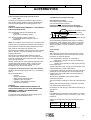
1. GENERAL INFORMATION
1.1.2 Conditions of use
1.1 INTRODUCTION
a) Generalities
A machine must only be installed, operated, by qualified
and trained persons.
1.1.0 General points
This manual provides installation, operating and
maintenance instructions for synchronous machines. It
also describes the basic construction of these machines.
This manual is general ; it applies to an entire group of
synchronous generators. Additionally, in order to make
information-finding easier, Section 1, "Characteristics and
Performance", has been included, describing the machine
completely (type of construction, type of bearing,
protection index, and so forth...); this will enable you to
determine exactly the chapters which apply to your
machine.
This synchronous machine has been designed for a
maximum length of service. To achieve this, it is necessary
to pay special attention to the chapter concerning the
periodic maintenance schedule for the machines.
1.1.1 Safety notes
The warnings "DANGER, CAUTION, NOTE" are used to
draw the user’s attention to different points:
DANGER :
THIS WARNING IS USED WHEN AN OPERATION,
PROCEDURE, OR USE MAY CAUSE PERSONAL
INJURY OR LOSS OF LIFE
CAUTION :
THIS WARNING IS USED WHEN AN OPERATION,
PROCEDURE, OR USE MAY CAUSE DAMAGE TO OR
DESTRUCTION OF EQUIPMENT
NOTE :
This warning is used when an operation, procedure, or
delicate installation requires clarification.
Any technical engineer operating, maintaining this machine
must be allowed to practice in regard with local working
laws (eg: to be certified to operate on high voltage
devices…)
A machine can only be operated for the duty foreseen by
its original tender.
The main data of this machine are summarized in "Section
1" of this manual
Any operating condition other than those specified by the
original tender must receive a Leroy Somer agreement
Any modification of the machine structure must receive a
Leroy Somer agreement
b) Vibratory analysis
It is the responsibility of the gen set manufacturer to
ensure that the different assembled system will be
vibratory compatible.(ISO 8528-9 and BS5000-3)
It is the responsibility of the gen set manufacturer to
ensure that the shaft line torsional analysis has been done
and accepted by the different parties (ISO 3046)
CAUTION :
EXCEEDING THE VIBRATORY LEVEL ALLOWED BY
THE STANDARD ISO 8528-9 & BS5000-3 MAY CREATE
HEAVY DAMAGES (BEARING DAMAGE, STRUCURE
CRACKS …).
EXCEEDING THE TORSIONAL VIBRATORY LEVEL OF
THE SHAFT LINE (ex: ABS, LLOYD …) MAY CREATE
HEAVY DAMAGES (CRANKSHAFT FAILURE ,
GENERATOR SHAFT FAILURE, …)
Refer to chapter 2.1.3 for further information about the
accepted vibration level of the standard ISO 8528-9 and
BS5000-3
7
SERVICE AND OPERATING MANUAL
LEROY SOMER
2327 en – 11.2011 / o
ALTERNATORS
1.2 GENERAL DESCRIPTION
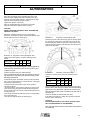
1.2.1 Generator
The synchronous generator is an alternating-current
machine, without rings or brushes. The machine is cooled
by the flow of air through the machine.
For a better comprehension, use the drawings of chapter
10.
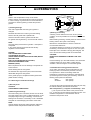
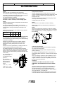
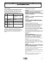
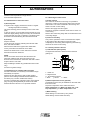
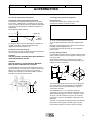
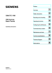
1.2.2 Excitation system
The excitation system is mounted on the side opposite the
coupling.
The excitation system comprises two assemblies:
The excitation armature, generating a three-phase current,
coupled with the three-phase rectifier bridge (comprised of
six diodes) supplies the excitation current to the generator
revolving field. The excitation armature and the rectifier
bridge are mounted on the synchronous generator rotor
shaft and are interconnected electrically with the revolving
field of the machine.
The excitation field winding (stator) is supplied by the
control (in direct current)
5
1
3
4
2
1- Excitation field winding
2- Excitation armature
3- Rotating diode bridge
4- Revolving field
5- Machine stator
8
SERVICE AND OPERATING MANUAL
LEROY SOMER
2327 en – 11.2011 / o
ALTERNATORS
2. DESCRIPTION OF SUB-ASSEMBLIES
2.1 STATOR
2.1.1 Electric machine armature
a) Mechanical description
The machine stator comprises low-loss steel laminations,
assembled under pressure. The steel laminations are
blocked axially by a welded ring. The stator coils are
inserted and blocked in the slots, then impregnated with
varnish, and polymerised to ensure maximum resistance to
mould, excellent dielectric rigidity and perfect mechanical
linking.
2.1.2 Excitation field winding
The excitation field winding comprises a solid element and
a winding.
The excitation is flanged on the rear end shield of the
machine.
The winding is made of enamelled copper wires.
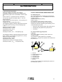
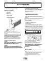
2.1.3 Stator protection
a) Heating resistor
The heating element avoids internal condensation during
the shutdown periods. It is connected to the main terminal
box strip. The heating resistor is switched on as soon as
the machine is shut down. It is located at the back end of
the machine.
The electrical characteristics are provided in Section 1
"Technical Characteristics".
To improve the machine protection the alarm set point may
be reduced following effective site information:
Alarm temperature (*) = Highest recorded temp + 10°K
Trip temperature (*) = Alarm temperature + 5 °K
(*) do not pass over the values of the previous chart.
(*)Highest recorded temp: Temperature measured at
the site in the worst temperature condition at the stator
temperature sensor
E.g. : a class B machine reached 110°C during a facto ry
heat run test. Set the alarm temperature to 120°C in stead
of 130°C as indicated in the previous chart. Set the
emergency shutdown to 115°C instead of 135°C as
indicated in the previous chart.
c) Stator air sensor
As an option an RTD or thermostat can measure the stator
air inlet temperature (cold air)
Stator air inlet temperature; Alarm points and shutdown:
• alarm
Nominal air inlet stator + 5 K
• shutdown
80°C
Stator air outlet temperature; Alarm points and shutdown:
• alarm
Nominal air inlet stator + 35K
• shutdown
Nominal air inlet stator + 40K
NOTE :
For an open drip proof machine the nominal air
temperature entering the stator corresponds to the ambiant
temperature
Inhibit the stator air sensor safety "alarm" for few seconds
during the machine start up;
NOTE:
For a water cooled machine (CACW) the nominal air
entering the stator may be approximated as following:
Tair entering stator = Twater entering cooler + 15°K
b) Stator winding temperature sensor
The temperature sensors are located in the active part of
the stack. They are located in the zone assumed to be the
hottest part of the machine. The sensors are connected to
a terminal box.
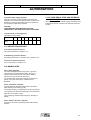
Depending on the temperature rise of the machine, the
temperature of the sensors should not exceed a maximum
of :
TEMP. RISE
class
ALARM
TRIP
Power (KVA)
< 5000
> 5000
< 5000
> 5000
B
130 °C
125 °C
135 °C
130 °C
F
155 °C
150 °C
160 °C
155 °C
H
175 °C
170 °C
180 °C
175 °C
9
SERVICE AND OPERATING MANUAL
LEROY SOMER
2327 en – 11.2011 / o
ALTERNATORS
d) Stator vibration sensor
This chapter concerns the setting of seismic probes. For
setting of proximity probes refer to the rotor
The vibration level of the machines is directly linked to the
duty and to the site characteristics.
The aluminium plates (E) are pressed against the winding,
acting as a heat dissipator and ensure excellent clamping
of these coils.
Support bars (C) on each pole protect the end windings
against the centrifugal force.
The revolving field-coil is heated and shrunk onto the shaft.
We propose the following adjustment:
Vibration Alarm (*) = Site Highest Vibration level + 50%
Vibration Trip = Vibration Alarm + 50%
(*) do not pass over the values of the following chart
The machines are engineered to be able to withstand the
vibration level specified by the standard ISO8528-9 and
BS5000-3
Maximum levels for : reciprocating Internal combustion
engines
Nominal speed
kVA
(rpm)
Generator vibration level
(nominal conditions)
Overall
Any harmonics
(mm/s rms)
(2–1000 Hz)
1300 à
721
à
2199
1299
≤ 720
> 250
The excitation coil is keyed and heat-shrunk onto the shaft.
< 20
≥ 250
< 20
>
1250
< 18
>
1250
< 15
< 0.5 mm ; pp
(5 – 8 Hz)
< 9 mm/s ; rm
(8 – 200 Hz)
< 10 (*)
(*) generator on concrete base
Maximum levels for : Turbines
Turbines
(hydraulic ; gaz ; steam)
2.2.2 Excitation armature
The excitation armature is constructed by stacking
magnetic steel laminations. These steel laminations are
held in place by rivets.
Max advised : 4.5
(overall ; mm/s rms)
2.2 ROTOR
2.2.1 Revolving field-coil
The revolving field coil comprises a stack of steel
laminations, stamped and cut to reproduce the indentation
of the projecting poles.
The steel lamination stack-up is terminated at each end
with high-conductivity electrical plates.
To enable parallel operation between machines, and in
order to ensure stability, high electrical conductivity bars
are inserted in holes crossing the poles from one side to
the other. These bars are welded with the stack end
laminations in order to obtain a complete cage winding (or
LEBLANC dampening cage).
The windings are enamelled copper wires, class "F"
insulation (or "H", depending on the customer's request or
size of the machine).
2.2.3 Fan (machines: IC 0 A1)
The synchronous machine is characterized by a selfventilation system. A centrifugal fan is mounted between
the revolving field coil and the front bearing.
Air intake is at the rear of the machine and the exhaust on
the drive end side.
The fan consists of a hub, which is keyed and heat-shrunk
onto the shaft. The flange is made of welded steel,
attached to the hub with hexagonal head-cap screws. The
ventilation effect is obtained through, inclined blades. The
air is exhausted by centrifugation. The air inlet and outlet
must remains free during operation
2.2.4 Rotating diode bridge
a) General points
The rectifier bridge, comprising six diodes, is placed at the
rear of the machine. The rotating bridge is made of glass
fibre with a printed circuit to connect the diodes together.
This bridge is supplied with alternating current by the
excitation armature and supplies direct current to the
revolving field-coil. The diodes are protected against over
voltage by rotating resistors, or by varistors. These
resistors (or varistors) are mounted in parallel with the
revolving field-coil.
The winding (B) is placed around the pole (A) and is
impregnated with epoxy resin (class F machine insulation)
or with varnish (class H machine insulation).
The winding is made of insulated flattened copper with
high electrical conductivity.
10
LEROY SOMER
SERVICE AND OPERATING MANUAL
2327 en – 11.2011 / o
ALTERNATORS
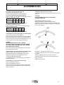
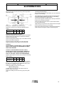
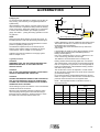
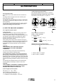
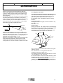
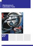
c) Rotating rectifier test
Carry out the test using a D.C. source as indicated below.
2
1
+
3
A diode in good condition should allow the current to flow
only in the anode-to-cathode direction.
Disconnect the diodes before the test.
3 ... 48 volts
-
-
+
1
1 - Field
2 - Rotating resistors
3 - Exciter armature
The inner and outer rings are connected to the revolving
field-coil
2
1 - Anode
2 - Cathode
1
Diode type
2
Positive
Negative
SKR
diode housing
diode wire
SKN
diode wire
diode housing
When reassembling ensure that the diodes are be
tightened to the correct torque
1 - Outer ring
2 - Inner ring
The diode fastening screws must be tightened to the
correct torque.
b) Tightening torque for the rotating diode fastening
screws
CAUTION :
THE ROTATING DIODE FASTENING SCREWS MUST
BE TIGHTENED USING A TORQUE WRENCH
CALIBRATED TO THE RECOMMENDED TORQUE.
Diode
Tightening torque
SKR 100/..
1.5 m.daN
SKR 130/..
1.5 m.daN
SKN 240/..
3 m.daN
2.2.5 Balancing
The entire rotor has been balanced according to ISO8221
standard in order to obtain a residual imbalance less than :
Gen set : Class G2.5
Turbine : Class G1
The balancing is carried out at two levels. The first is that
of the fan. It is recommended, when the fan is refitted
(after servicing) to respect the initial indexing.
The second is that of the shaft end. The shaft end is coldstamped to indicate the type of balancing.
H : balancing with Half-key carried out as
standard
F : balancing with Full key
N : balancing without key (None)
The coupling must be balanced to fit the generator rotor
balancing.
2.2.6 Rotor vibration sensor
This chapter concerns the setting of proximity probes. For
setting of seismic probes refer to the stator chapter
The vibration level of the machines is directly linked to the
duty and to the site characteristics.
We propose the following adjustment:
Vibration Alarm (*) = 50% of the Bearing shell gap
Vibration Trip = 75% of the Bearing shell gap
11
LEROY SOMER
SERVICE AND OPERATING MANUAL
2327 en – 11.2011 / o
ALTERNATORS
2.3 ANTI FRICTION-BEARINGS
2.3.0 Description of antifriction bearings
The bearings are installed at each end of the machine.
They can be replaced.
The bearings are protected from external dust by labyrinth
seals.
The bearings must be lubricated regularly. The old grease
is forced out at the lower part of the bearings by the force
of the new grease being injected.
2.3.1 Start-up of antifriction bearings
The bearings are pre-lubricated in the factory, but before
they are put into service, it is necessary to complete this
lubrication.
CAUTION
UPON START-UP, GREASE THE MACHINE WHILE IT IS
RUNNING SO AS TO FILL ALL THE FREE SPACES IN
THE GREASING DEVICE
Record the temperature of the bearings during the initial
operating hours. Poor lubrication can cause abnormal
heating.
If the bearing hisses, lubricate it immediately. Some
bearings may make a clattering noise if they do not
operate at normal temperature. This may occur if the
weather is very cold or when the machine is operating
under abnormal temperature conditions (start-up phase,
for example). The bearings will become quieter after
having reached their normal operating temperature.
2.3.2 Storage of machine with anti friction bearings
This chapter must be taken in consideration if a machine is
stopped more than 6 months.
Grease the bearings , machine stopped , inject two time
the grease volume used for a standard maintenance.
Every 6 months turn the the machine shaft line of few
turns. Then inject a standard grease volume
2.3.3 Maintenance of antifriction bearings
a) General points
Antifriction bearings or ball bearings do not require special
maintenance.
They must be lubricated regularly with the same type of
grease as used in the factory. For information concerning
the lubrication quantity and interval, refer to Section 1 :
"Characteristics and Performance".
CAUTION :
LUBRICATION MUST BE CARRIED OUT AT LEAST
EVERY 6 MONTHS
CAUTION :
IT MUST BE DANGEROUS TO MIX GREASES WHICH
HAVE DIFFERENT SOAP BASE. IT IS NECESSARY TO
GET THE GREASE SUPPLIER APPROVAL OR TO
CLEAN THE BEARING BEFORE TO PROCEED
NOTE:
After a regreasing the bearing temperature may increase
of 10 to 20°C
This temporary temperature increase may stay few tens of
hours
NOTE:
For re greasing period lower than 2000 hours we
recommend to install a continuous greasing system to limit
the maintenance operators visit
These type of system must be disable during machine stop
The grease contained in these systems must not be stored
over a period of 1 year
b) Lubricant
Recommended lubricant:
SKF LGWA2
SHELL GADUS S3 V220C (lithium complex base).
SHELL RETINAX LX2 (lithium complex base).
CASTROL LMX NLGI2
TOTAL Multis complex EP2
Recommendation for a grease choice ::
Mineral oil or PAO (SHC)
Base (soap ) grade NLGI 2
Lithium complex base
Base oil viscosity at 40°C: 100 to 200 mm2/s
Dye penetration test (DIN 51817) : 2% minimum
Use of grease which do not fit to the recomended figure
(substitution grease) :
Mineral oil or PAO (SHC)
Base (soap ) grade NLGI 2 or NLGI 3
Lithium base
Base oil viscosity at 40°C: 100 to 200 mm2/s
Dye penetration test (DIN 51817) : 2% minimum
CAUTION :
THE USE OF A SUBSTITUTION GREASE CONDUCE TO
REDUCE THE RE GREASING PERIOD OF 30%
12
LEROY SOMER
SERVICE AND OPERATING MANUAL
2327 en – 11.2011 / o
ALTERNATORS
NOTE:
Lithium and complex lithium soap can be mixed
Lithium complex and calcium lithium soap can be mixed
In case of change of grease brand it is recommended to
proceed to a massive greasing to waste the previous
grease.
c) Cleaning bearings
This note is applicable when the type of grease is
changed.
Dismantle the machine in order to get to the bearing
Remove the old grease with a palette knife.
Clean the lubricator and the grease removal tube.
For greater cleaning efficiency, use a brush with solvent.
NOTE:
The most widely-used solvent is gasoline : white spirit is
acceptable.
In any cases national environmental and sanitary
regulation must be fulfilled.
DANGER:
THE PROHIBITED SOLVENTS ARE:
CHLORINATED SOLVENT
(TRICHLORETHYLENE,TRICHLOROETHANE) WHICH
BECOMES ACID
FUEL-OIL (EVAPORATES TOO SLOWLY)
GASOLINE CONTAINING LEAD
BENZINE (TOXIC)
Blow compressed air onto the bearings to evaporate the
excess solvent.
Fill the bearing with the new grease.
Re-assemble the cage and the parts, which have been
dismantled, filling them with grease.
Use a grease pump to complete the bearing lubrication
(while machine running)
2.3.4 Servicing the antifriction bearings
a) General points
CAUTION:
CLEANLINESS IS IMPERATIVE
b) Removing the bearings
The inner bearing race is mounted, shrunk onto the shaft.
The outer bearing race is free, or slightly tightened, on the
hub (depending on the type of bearing). To remove the
bearing from the shaft, it is necessary to use a dedicated
hub-puller to avoid damaging the surface of the shaft.
c) Bearing re-assembly
A bearing can be refitted if it is known to be in perfect
condition As far as possible we recommend to use a new
bearing
Before refitting a bearing, carefully clean the surface of the
bearing and the other parts of the bearing.
Measure the shaft diameter to check it is within the
recommended tolerances.
To install the bearing on the shaft, it is necessary to heat
the bearing. The heat source may be an oven or a space
heater (the use of oil baths is strongly discouraged). The
use of an induction bearing heater is recommended.
CAUTION:
NEVER HEAT A BEARING TO MORE THAN 125°C
(257°F)
Push the bearing up to the shaft shoulder, and check after
cooling that the inner ring is still in contact with the
shoulder. Lubricate using the recommended grease.
2.3.5 Antifriction bearing protection devices
As an option, the bearing may be protected from overheating by RTD or PTC sensors (customer’s choice)..
For special use in warm surroundings where the
temperature of the bearings exceeds the authorised limit
(for a bearing known to be in good condition), contact us.
Bearing; Alarm points and shutdown:
• alarm
90°C (194°F)
• shutdown
95°C (203°F)
To improve the machine protection the alarm set point may
be reduced following site effective information:
Alarm temperature (*) = Highest recorded temp + 15°K
(*) do not pass over the values of the previous chart.
E.g. : At site the common bearing temperature is 60°C . Set
the alarm temperature to 75°C instead of 90°C as
indicated in the previous chart
NOTE:
Heat the bearing during the pulling operation makes the
operation easier and prevent the shaft from scratch.
13
SERVICE AND OPERATING MANUAL
LEROY SOMER
2327 en – 11.2011 / o
ALTERNATORS
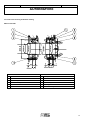
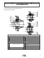
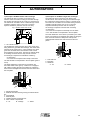
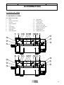
2.3.9 Anti friction bearing installation drawing
Machine type A50
Drive end
Non drive end
1
End shield
5
O-Ring
2
End cover
6
Non drive end shield
3
Ball bearing 6226 C3
7
End cover
4
End cover fixing screw
8
Ball bearing 6226 C3
9
Bearing pre load washer
10
End cover fixing screw
14
LEROY SOMER
SERVICE AND OPERATING MANUAL
2327 en – 11.2011 / o
ALTERNATORS
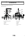
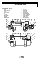
2.3.9 Anti friction bearing installation drawing (following)
Machine type A52.2; Two bearings
Bearing assembly "Power plant"
Drive end
Non Drive end
1
End cover
5
End shield
2
End cover fixing screw
6
End cover fixing screw
3
Ball bearing 6232 MC3
7
End cover
4
End shield
8
Roller bearing NU 1028 MC3
Bearing assembly " Marine "
Drive end
1
2
same as à "power plant"
Non Drive end
9
End shield
10
End cover
3
11
End cover fixing screw
4
12
Bearing pre load spring
13
Ball bearing 6226 C3
14
O-Ring
15
LEROY SOMER
SERVICE AND OPERATING MANUAL
2327 en – 11.2011 / o
ALTERNATORS
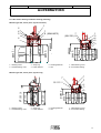
2.3.9 Anti friction bearing installation drawing (following)
Machines A53 and A54 :
Drive end side (2 bearing machine)
Non drive end side
1 – End shield
1 – End shield
2 – M12 stud
2 – M12 stud
3 – End cover
3 – End cover
4 - Shaft
4 – Shaft
5 – Ball bearing 6232 MC3
5 – Ball bearing 6328 MC3
6 – Spring
16
SERVICE AND OPERATING MANUAL
LEROY SOMER
2327 en – 11.2011 / o
ALTERNATORS
2.3.9 Anti friction bearing installation drawing (following)
Machine type A56 ; Power plant (6 poles and more)
1
2
4
5
7
8 (6248 MC3)
7
(NU 232) 8
1
2
4
5
3
1 – Bearing carrier
2 - Outside bearing cover
3 – Snap ring
4 - Fixed deflector
5 - Rotating deflector
6 - Nut
0
Ø158 -0,1
Ø155 ±0,1
Ø160n5
0
-0,1
Ø180
Ø290K6
Ø440J6
Ø260
0
-0,1
Ø240n6
Ø235
0
-0,1
Tr240x4
6
7 - Inside bearing cover
8 – Anti friction bearing
Machine type A56 ; Power plant (4 poles only)
1 – Bearing carrier
2 - Outside bearing cover
3 – Snap ring
4 - Fixed deflector
5 - Rotating deflector
6 - Nut
Ø158
Ø155 ±0,1
Ø160n5
0
-0,1
Ø180
Ø290K6
O 220
0
-0.1
O 180 n5
0
-0.1
O 175
O 380 J6
(NU 232) 8
0
-0,1
1
2
4
5
6
7
7 - Inside bearing cover
8 – Anti friction bearing
17
LEROY SOMER
SERVICE AND OPERATING MANUAL
2327 en – 11.2011 / o
ALTERNATORS
2.4 SLEEVE BEARINGS
Note : For vertical machines refer to the attached specific
bearing notice.
Refer to the attached cut view in "chapter 10" for an easier
understanding
c) Operating description of Oil circulation bearing
Proceed as for the self-lubricated bearings.
For special duty of high speed machine or high loaded
bearing it might be necessary to have an oil circulation
system (external device which ensure the cooling and the
circulation of the oil)
2.4.0 Description of horizontal Sleeve bearings
The oil warmed by the bearing losses is externally cooled
and is returned directly to the shell. To obtain efficient
cooling the oil flow must be correct (refer to section 1).
a) Physical description
Rotation of the machine rotor is guided by Sleeve
bearings.
2.4.1 Electrical insulation of Sleeve bearings
The bearing housing is constructed in two ribbed parts
providing considerable heat extraction potential.
The sleeve bearing comprises two half-shells with an
external spherical shape. This allows self-alignment. The
guiding surfaces of the sleeve bearing are covered with tinbased anti-friction metal.
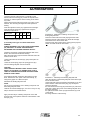
a) Illustration diagram of the insulating film
Following the used technology shaft circulating current
may occurs. When necessary, ACEO insulates the Non
Drive End bearing to avoid shaft-circulating current.
An insulating film is applied to the bearing housing
spherical seat.
The spherical seat of the housing of the electrically
insulated bearings is covered with an insulating coating.
The positioning pin of the sleeve bearing in the housing is
also insulated with an insulating bush.
The lubrication ring, mounted free on the shaft, is made of
brass. In order to simplify dismantling, the ring is cut in two
parts, assembled using screws.
A guide for the lubrication ring (synthetic materials) is
attached to the upper bearing half-shell (for marine
applications only).
The floating labyrinth seals are cut in two parts, held
together by an expandable ring. These seals are inserted
in a support. A seal-positioning pin rests in the support to
block it during rotation.
The upper part of the housing is closed by means of a
glass plug allowing observation of the rotation of the
lubrication ring. A threaded metal plug allows the bearing
to be filled with oil.
1 – Electrical insulation
CAUTION:
WHEN INSULATED BEARING IS USED THE
ACCESSORIES IN CONTACT WITH THE SHELL MUST
BE ELECTRICALLY INSULATED (TEMPERATURE
SENSOR …)
The lower housing may be equipped with an oil-level sight
indicator, a thermometer and a temperature sensor.
b) Operating description of Self-lubricating bearing
Upon stopping, the shaft rests on the lower bearing; there
is metal-to-metal contact.
During the start-up phase, the shaft rubs against the antifriction metal of the bearing. Oil lubrication is used.
After having reached its transition speed, the shaft creates
its oil film. At this point there is no further contact between
the shaft and bearing.
CAUTION:
PROLONGED OPERATION AT EXTREMELY SLOW
ROTATION SPEEDS (SEVERAL rpm) WITHOUT
LUBRICATION COULD SERIOUSLY DAMAGE THE
SERVICE LIFE OF THE BEARING.
18
LEROY SOMER
SERVICE AND OPERATING MANUAL
2327 en – 11.2011 / o
ALTERNATORS
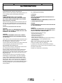
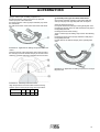
b) Insulation check
Single bearing machine:
Maintain the rotor at the drive end side to insulate it from
the earth (disconnect the coupling if not done). Measure
the insulating resistance between the shaft and the
ground. The insulation should be better than 0.1 MΩ.
measured under 500 V DC
1
4
2
c) Long term storage
When a sleeve bearing machine has to be stopped for
more than one year:
Drain the bearing. Place a "Silicagel" gag inside the
bearing oil sump (it is necessary to open the bearing
housing to proceed)
Place an adhesive strip along the parting lines of the
housing.
Pour the recommended protecting agent through the oil
filling hole of the bearing (around 50 cc). Turn the shaft
several times in order to spread the product evenly
throughout the bearing.
3
5
1 - Bearing shell
2- Insulating film
3 - Bearing housing
4 - Rotor
5 - Insulating wedging
Double bearing machine:
Maintain the rotor at the drive end side to insulate it from
the earth (disconnects the coupling; Dismount the drive
end bearing if not done). Measure the insulating resistance
between the shaft and the ground. The insulation should
be better than 0.1 MΩ. measured under 500 V DC
Installed shell accessories (e.g: RTD) must fit 0.1 MΩ.
measured under 500 V DC
2.4.2 Storage of Sleeve bearings machine
a) General points
CAUTION:
A VISIT OF THE BEARING (research of corrosion
marks) MUST BE DONE AT LEAST ONCE PER YEAR
CAUTION:
BEFORE START UP IT WILL BE NECESSARY TO
REMOVE THE "SILICAGEL" BAG AND TAPES
2.4.3 Oil circulation installation
Refer to chapter 2.6
2.4.4 Start-up of Sleeve bearings
a) General check before start up
To identify your bearing characteristics refer to section 1
This verification must be carried out upon the first start-up,
during periodic inspection of the bearing, or as soon as
any part of the bearing alignment is changed (coupling ...).
After a long shutdown period, proceed following the used
storage procedure (refer to chapter 2.4.2)
CAUTION:
FOR MINERAL OIL WE RECOMMEND THE USE OF
TECTYL PRODUCTS FROM "VALVOLINE GmbH" SUCH
AS TYPE "511 M"
FOR SYNTHETIC OIL WE RECOMMEND THE USE OF
"JELT 003400" SPRAY FROM "ITW SPRAYTEC"
Check that the shaft has not corroded (onto journal
surface; thrust faces and seals surfaces)
NOTE :
It is possible to start the machine up without removing the
recommended protection agent.
Clean the external parts of the bearing. Dust and dirt
impede the radiation of the heat
Fill the bearing oil cavities with oil.
CAUTION:
THE BEARINGS ARE DELIVERED WITHOUT OIL
Check if the temperature monitoring equipment works.
b) Short term storage
When a sleeve bearing machine has to be stopped for
more than one month and less than one year:
Do not drain the bearing
Pour the recommended protecting agent through the oil
filling hole of the bearing (around 50 cc). Turn the shaft
several times in order to spread the product evenly
throughout the bearing.
19
SERVICE AND OPERATING MANUAL
LEROY SOMER
2327 en – 11.2011 / o
ALTERNATORS
b) Self-lubricating bearings start up data
To identify your bearing characteristics refer to section 1
Fill the bearing with the recommended oil. The oil must be
new, absolutely free of any traces of dust or water.
The oil level limits are as follows:
minimum oil level: bottom of the oil sight glass
maximum oil level: 2/3 the top of the oil sight glass
NOTE: It is recommended to filter the oil before filling the
bearing.
CAUTION:
NOT ENOUGH LUBRICANT LEADS TO TEMPERATURE
RISES AND THUS TO DAMAGE TO THE BEARING.
TOO MUCH LUBRICANT LEADS TO LEAKAGES.
Retighten the split line and flange screws (12) by using the
following torque values:
Bearing Size
14
18
22
28
Torque [Nm]
(lightly oiled)
170
330
570
1150
d) Oil circulation bearing with non accurate oil flow
(+0% ; -40%)
To identify your bearing characteristics refer to section 1
This chapter typically applies for standard bearings (as for
bearing types E..Z.K ; E..Z.Q).
The oil circulating bearings (without Leroy Somer
lubricating system) are delivered with:
a breather
an oil inlet flow regulating system.
The "oil flow regulating system" consists of :
an adjustable pressure reducing valve "A"
a diaphragm.
NOTE: The breather can be removed if it is proved that the
bearing casing is in depressure regarding the atmosphere.
Fit a plug tin place of the breather
The oil flow adjustment does not request high accuracy.
Do not feed the bearing with an oil flow higher than this
one indicated in section 1.
Ensure that the complete oil supply and return lines have
been rinsed as instructed in the chapter.2.4.3
Check the firm position of the oil sight glass (23).
Ensure that the installation instructions have been followed
(refer to chapter.2.4.3 ) such as filtering unit, return line
properly inclined etc.
If a temperature sensor or thermometer is used check they
are correctly fixed.
Proceed as for the self-lubricated bearings and then
start the oil supply system (pump etc.).
Retighten all screw plugs in the connection holes (4), (22),
(24) (27) by using the necessary torque values:
To adjust the oil flow as recommended in section 1:
Machine stopped, adjust the pressure reducing valve "A" to
get the bearing oil level at the middle of the glass. And
then run the generator
Check the firm position of the top sight glass (5).
Plugs threads
G 3/8
G 1/2
G 3/4
G1
Torque [Nm]
30
40
60
110
G2
G 2 1/2
320
500
Plugs threads
Torque [Nm]
G 1 1/4 G 1 1/2
160
230
Check the operation of the temperature monitoring
equipment.
Machine running and oil at the operating temperature the
oil sight glass level should be within 1/3 and ½ of the
glass. If necessary readjust the pressure reducing valve
"A"
A
During the start-up period, check the temperature of the
bearings. The temperature should stay below 95°C an d
then drop down to the temperature normally recommended
(refer to the technical characteristics for Sleeve bearings in
Section 1.)
In case of oil oozing retighten the bearing fixing screws
and the plugs to the recommended torque.
c) Water cooled bearing (type EFW..) start up data
To identify your bearing characteristics refer to section 1
During generator operation the oil level in the bearing must
comply with the indications in Chapter 2.4.5.
Proceed as for the self-lubricated bearings and
check the water flow of the cooler. (refer to the data
contained in section 1)
Water has to be filtered as per chapter 2.7.5
20
LEROY SOMER
SERVICE AND OPERATING MANUAL
2327 en – 11.2011 / o
ALTERNATORS
e) Oil circulation bearing with accurate oil flow
(+5% ; -10%)
To identify your bearing characteristics refer to section 1
This chapter typically applies for bearings engineered for
heavy thrust (tilting pads as for bearing types E..Z.A).
CAUTION:
THE OIL FLOW MUST BE CARREFULLY ADJUSTED TO
THE REQUESTED VALUE
The oil circulating bearings are delivered with:
a breather
an oil inlet flow regulating system.
The "oil inlet regulating system" consists of :
an adjustable pressure reducing valve "A"
a diaphragm.
NOTE: The breather can be removed if it is proved that the
bearing casing is in depressure regarding the atmosphere
Ensure that the complete oil supply and return lines have
been rinsed as instructed in the chapter.2.4.3
Ensure that the installation instructions have been followed
(refer to chapter.2.4.3) such as filtering unit, return line
properly inclined etc.
Proceed as for the self-lubricated bearings and then
start the oil supply system (pump etc.). The oil flow must
be strictly adjusted within the requested value using a flow
meter. Run the generator.
Machine running and oil at the operating temperature the
oil sight glass level should be within 1/3 and 2/3 of the
glass. If the level reach the top of the oil sight glass
investigate for the oil return line design.
f) Inspection of Sleeve bearings at the end of start-up
Supervise the bearing during the trial run ( 5-10 operating
hours ).
Pay special attention to:
- oil level
- bearing temperature
- sliding noises of the shaft seals
- tightness of the sump plugs
- tightness of the bearing accessories
- occurrence of vibrations.
CAUTION :
IF THE BEARING TEMPERATURE EXCEEDS THE
CALCULATED VALUE OF 15 k STOP THE MACHINE
IMMEDIATELY. INSPECT THE BEARING AND
DETERMINE THE CAUSES.
In case of oil oozing retighten the bearing fixing screws
and plugs to the recommended torque
2.4.5 Maintenance of Sleeve bearings
a) Verification of oil-level
Check the oil level at regular intervals.
The oil level limits are as follows:
minimum oil level: bottom of the oil sight glass
maximum oil level: 2/3 the top of the oil sight glass
2/3
Maximum admissible oil level
Optimum top oil level
Optimum bottom oil level
1/2 1/3
Minimum admissible oil level
b) Temperature verification
Check the bearing temperature and record it. A bearing
temperature, which suddenly varies without any obvious
reason (change of ambient temperature etc.), indicates
abnormal operation. It is then necessary to inspect the
bearing.
c) Oil draining
NOTE:
Risk of pollution! Please observe the instructions for the
use of the lubricating oil. The manufacturer can provide
information on waste oil disposal
It is recommended to drain the oil at intervals of
8000 hours of operation in dirty environment (eg :
gen set application)
16000 hours of operation in clean environment (eg :
hydro power plant)
A yearly inspection of the oil sump is recommended. Have
a special attention to water contamination.
It is possible to decide the oil change only after making an
analysis and not at fixed period. In such practice the oil
analysis report must fulfill pollution recommendation of
chapter "2.4.10-e":
Shut down the installation and secured it against
unintended operation.
Take all necessary measures to collect all of the lubricating
oil.
Release the lubricating oil while it is still warm. Impurities
and residues will thus be removed.
Unscrew the oil drain plug (27). Release the lubricating oil
and collect it.
NOTE:
If the lubricating oil contains unusual residues or is visibly
changed, eliminate the causes. If necessary, carry out an
inspection.
Tighten the oil drain plug (27) using the following torque
values:
Bearing size
14
18
22
28
Torque [Nm]
30
40
60
60
Remove the screw plugs from the oil filler hole (4).
21
SERVICE AND OPERATING MANUAL
LEROY SOMER
2327 en – 11.2011 / o
ALTERNATORS
NOTE:
Make sure that no impurities get into the bearing.
Use a lubricant with the viscosity indicated on the bearing
type plate. Fill the lubricant through the oil filler hole (4) up
to the middle point of the oil sight glass (23).
The oil level limits are as follows:
minimum oil level: bottom of the oil sight glass
maximum oil level: 2/3 the top of the oil sight glass
NOTE:
Insufficient lubricant leads to temperature rises and thus to
damage to the bearing.
Too much lubricant leads to leakage. In the case of
bearings lubricated by a loose oil ring, too much lubricant
could break the oil ring, thus leading to damage to the
bearing.
Tighten the screw plug into the oil filler hole (4) using the
following torque values:
14
18
22
28
Torque [Nm]
30
40
60
60
Example: The oil return line (of a circulation bearing)
opening directly into a diesel motor lower sump and
allowing the housing back-pressure to return to the
bearing.
Example: A vacuum generated by a coupling located too
close the Sleeve bearing and acting as a fan.
The relative depression (or pressure) during operation
must remain less than 5 mm of water column. The relative
pressure is the pressure difference existing between the
bearing oil sump and the bearing outside (measured close
to the seals).
Pi
∆ (Pe - Pi) < 50Pa
∆ (Pm - Pi) < 50Pa
Note: 50Pa=5mmWC
Partially fill the pipe with water.
NOTE:
Be careful not to cause water to enter the bearing
Measure the pressure (or depression) in millimeters of
water column.
NOTE:
Given the low pressures measured, to make the reading
easier it is advised to incline the water column manometer
by 5.7° (diagram below). A reading amplification of "10" is
thus obtained.
5,7°
10 mm
100 mm
99mm
5,7°
e) Oil for sleeve bearing
We do not have any special recommendation regarding
any mineral oil manufacturer.
The used oil must comply with the requested viscosity
(refer to Section 1).
For frequent cold starting (lower than -15°C) witho ut oil
sump heater please contact us. A new oil viscosity may be
advised.
Use a non-foaming mineral oil, without additives. If an oil
containing additives has to be used, make sure that the
supplier confirms the chemical compatibility of the oil and
the lead anti-friction properties.
Pi : bearing oil sump
pressure
Pm : machine
expansion chamber
(gain access as
indicated by the
arrow)
Install the pressure tap in place of the filling plug located
on the top of the bearing housing.
50 mm
d) Pressure measurement of a Sleeve bearing housing
The external environment of the electric machine may
cause pressurizing or depressurizing of the Sleeve bearing
and lead to oil leakage.
Pe : external pressure
close to the seal
Connect a flexible transparent tube to the upper part of the
bearing. Connect a pressure tap corresponding to the
flexible tube used.
5 mm
Bearing size
Field pressure measure :
Using a transparent tube as water column manometer.
CAUTION:
SYNTHETIC OILS MAY BE USED ONLY IF USED
LUBRICANT ARE ISSUED FROM THE FOLLOWING
LIST
Pe
Pm
Since the synthetic lubricants are not standardized, no
guarantee can be given regarding their chemical and
mechanical behavior. Some synthetic lubricant may
become acid and destroys bearing parts (white metal, oil
ring, sight indicator..) in a short time
If synthetic oil has to be used; during the first 2000 hours
of use the lubricant should be checked at short intervals.
22
SERVICE AND OPERATING MANUAL
LEROY SOMER
2327 en – 11.2011 / o
ALTERNATORS
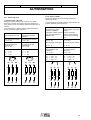
Viscosity data (for information) :
Few examples of mineral oil:
x
850
775
700
625
550
500
450
400
365
315
280
240
205
175
140
115
85
60
40
20
10
viscosity viscosity
(cSt ; 40°C)
ISO
y
680
140
460
320
220
90
50
40
150
100
68
46
32
22
85
30
80
20
75
10W
0W & 5W
A
B
x - CST at 40°C
y - CST at 100°C
A - ISO (VG)
B - SAE J306c Transmissions
C - SAE J300d motors
42
40
38
36
34
32
30
28
26
24
22
20
18
16
14
12
10
8
6
4
2
Type
ARAL
VG 32
VG 46
VG 68
32
46
68
BP
VG 32
VG 46
VG 68
31,5
46
68
Energol CS 32
Energol CS 46
Energol CS 68
CHEVRON
VG 32
VG 46
VG 68
30,1
43,8
61,9
Mechanism LPS 32
Mechanism LPS 46
Mechanism LPS 68
ESSO
VG 32
VG 46
VG 68
30
43
64
TERESSO 32
TERESSO 46
TERESSO 68
MOBIL
VG 32
VG 46
VG 68
30
43
64
D.T.E. Oil Light
D.T.E. Oil Medium
D.T.E. Oil Heavy Medium
SHELL
VG 32
VG 46
VG 68
32
46
68
Tellus Oil 32
Tellus Oil 46
Tellus Oil 68
C
Vitam GF 32
Degol CL46
Degol CL 68
The only synthetic lubricant allowed are those one issued
from the following list
Type
viscosité
(cSt ; 40°C)
KLUBER
32
44
62
81
Summit SH 32
Summit SH 46
Summit SH 68
Summit SH 100
MOBIL
31
65
SHC 624
SHC 626
SHELL
32
48
68
Madrella Oil AS 32
Madrella Oil AS 46
Madrella Oil AS 68
f) Oil sump capacity (liters)
Bearing EFxxx
14
18
22
28
Volume (l)
8
13
21
34
23
LEROY SOMER
SERVICE AND OPERATING MANUAL
2327 en – 11.2011 / o
ALTERNATORS
g) Sealing Compound
Mineral oil.
On split surfaces it is possible to use following compounds
(never dry):
Loctite 128068
"Hylomar M ; Marton-Domsel"
"Universal-Dichtmasse 200 PU ; Reinz-Dichtungs-gmbh"
On split surfaces only (do not use on floating labyrinth
seals) it is possible to use following compounds :
Terostat-9140 ; Teroson
Blue silicone RTV n°6 ; Loctite
Blue RTV 6B ; Permatex
Hi-Temp RTV FAG 26B ; Permatex
NOTE:
We do not recommend the use of sealing compound onto
the floating labyrinth seals.
However for certain leakage type , the use of "Curyl T" may
help to solve the encountered issue.
CAUTION
COMPOUND WITH SILICONE BASE CAN POLLUTE
THE SYNTHETIC OIL BATH. THE USE OF SILICONE
BASE COMPOUND CAN BE DONE ONLY AFTER
CHECKING COMPATIBILITY WITH OIL
MANUFACTURER.
2.4.6 Dismantling
a) Tools and equipment
The following tools and equipment are necessary:
- Allan key set
- Wrenching key set
- Open-jaw spanner set
- Feeler gauges (up 0.05mm)
- Caliper gauge
- Emery paper, Sleeve scraper
- Lifting equipment
- Permanent sealing compound (refer to chapter 2.4.5)
- Clean cloth
- Oil with the viscosity indicated (see bearing type plate)
- Detergents
- Liquid screw locking compound (e.g. LOCTITE 242)
- Liquid sealing compound and Teflon tape.
DANGER
BEFORE TRANSPORTING OR LIFTING CHECK IF THE
EYE BOLTS ARE TIGHT! INSECURE EYE BOLTS
COULD RESULT IN THE BEARING BECOMING LOOSE.
BEFORE MOVING THE BEARING BY THE EYE BOLTS
MAKE SURE THAT THE SPLIT LINE SCREWS ARE
TIGHTENED, OTHERWISE THE BOTTOM HALF OF THE
BEARING COULD BECOME DETACHED.
MAKE SURE THAT THE EYE BOLTS ARE NOT EX
POSED TO BENDING STRESS, OTHERWISE THE
BOLTS COULD BREAK.
Follow exactly the instructions for the use of the lifting
equipment.
NOTE:
Make sure that the work place is clean. Contamination and
damage to the bearing, especially of the running surfaces,
have a negative influence on the operating quality and
could lead to premature damage.
Shut down the installation and ensure that any unintended
operation is prevented.
Interrupt the cooling water supply (EFW.. bearing only).
Remove all thermo sensors from the connection holes.
Take all necessary measures to collect the lubricating oil.
Unscrew the oil drain plug (27) and collect the lubricating
oil (refer to chapter 2.4.5.c)
b) Lifting equipment
The following steps are to be observed before using the
lifting equipment:
To transport the complete bearing unit
Check if the split line screws are tight (12):
Check if the eye bolts are tight (6).
Connect the lifting equipment to the eye bolts (6).
24
SERVICE AND OPERATING MANUAL
LEROY SOMER
2327 en – 11.2011 / o
ALTERNATORS
To transport the top half of the housing
Check if the eye bolts are tight (6).
Connect the lifting equipment to the eye bolts (6).
To transport the bottom half of the housing
Screw 2 eye bolts (6) with suitable threads tight into the tap
holes (17) marked with a cross.
Bearing size
Tap hole
14
18
22
Connect the lifting equipment to the eye bolts (6).
To transport the Bearing shells
Screw 2 eye bolts or screw hooks with suitable threads
tight into the tap holes (9):
22
CAUTION:
DO NOT DAMAGE THE THRUST AND RADIAL
RUNNING SURFACES.
28
M 16 M 20 M 24 M 30
18
f) Removal of the top half of the shell
Unscrew the split line screws (19) and lift the top half of the
shell (11).
Bearing size
14
Tap hole
M 8 M 12 M 12 M 16
g) Dismantling of the loose oil ring
Open both split lines of the loose oil ring (44) by
untightening and removing the screws (47). Separate both
halves of the loose oil ring (44) carefully without using any
tools or other devices.
28
Connect the lifting equipment to the screw hooks.
c) Dismantling of the shaft seal type 10 (outboard side)
Loosen all screws (55) and turn them off.
Remove simultaneously in axial direction both top half (48)
and bottom half (51) of the seal carrier from the housing.
Shift the top half of the seal (53) a little (about 20 mm ). Tilt
it over carefully until the hook spring (49) unbends.
DANGER:
DURING DISMANTLING OF THE FLOATING
LABYRINTH SEAL HOLD TIGHT THE HOOK SPRING
(38). THIS IS UNDER TENSION AND COULD SPRING
BACK AND LEAD TO INJURY.
Open the hook spring (49) and remove the bottom half of
the seal (52) from the shaft.
d) Dismantling of the shaft seal type 20 (outboard side)
Untight all seals fixing screw (49) and remove them.
Simultaneously remove in axial direction both top and
bottom (48) ,(52) halves of the rigid labyrinth seal.
- Remove the split line screws (50).
- Separate the top half of the rigid labyrinth seal (59) from
the bottom half (63).
Illustration 1 : Opening of the loose oil ring
To check the geometry of the loose oil ring put it together
as follows:
Press the positioning pin (45) into the holes (46).
Adjust both halves of the loose oil ring till the split lines
match each other.
Tighten the screws (47).
e) Dismantling of the top half of the housing
Remove the flange screws (8).
Remove the split line screws (12).
Lift the top part of the housing (1) until the top part of the
housing can be moved in axial line over the bearing shell,
without touching it.
25
LEROY SOMER
SERVICE AND OPERATING MANUAL
2327 en – 11.2011 / o
ALTERNATORS
h) Dismantling the machine side shaft seal
Shift the top half of the seal (53) a little (about 20 mm). Tilt
it over carefully until the hook spring (49) unbends.
DANGER:
DURING DISMANTLING OF THE FLOATING
LABYRINTH SEAL HOLD TIGHT THE HOOK SPRING
(38). THIS IS UNDER TENSION AND COULD SPRING
BACK AND LEAD TO INJURY.
Open the hook spring (49) and turn the bottom half of the
seal (52) in the opposite direction to the anti-rotation pin
out of the integrated seal groove of the bottom half of the
housing.
2.4.7 Cleaning and checking
a) Cleaning
CAUTION:
USE ONLY NON-AGGRESSIVE DETERGENTS SUCH
AS FOR INSTANCE
· VALVOLINE 150
· ALKALINE CLEANING COMPOUNDS (PH-VALUE 6 TO
9, SHORT REACTION TIME).
DANGER:
PLEASE OBSERVE THE INSTRUCTIONS FOR THE USE
OF THE DETERGENTS.
i) Removal of the bottom half of the shell
CAUTION:
MAKE SURE THAT ALL BEARINGS MOUNTED ON A
SHAFT LINE ARE OPENED. LOOSEN THE SPLIT LINE
SCREWS OF THE HOUSINGS.
CAUTION:
THE LIFTING EQUIPMENT SHOULD NOT COME IN
TOUCH WITH THE SEAL AND RUNNING SURFACES
OF THE SHAFT.
Lift the shaft up to the point where shaft and bottom half of
the shell (13) do not touch each other any more. Protect
the shaft against unintended movement.
CAUTION:
NEVER USE CLEANING WOOL OR CLOTH. RESIDUES
OF SUCH MATERIALS LEFT IN THE BEARING COULD
LEAD TO EXCESSIVE TEMPERATURES.
Clean the following parts thoroughly :
top half of the housing (1)
bottom half of the housing (21)
top half of the shell (11)
bottom half of the shell (13)
sealing surfaces of the top half (48) and bottom half (51)
of the seal carrier or of the rigid labyrinth seal
loose oil ring (44).
Water cooler cleaning (bearing type EFW.. only)
Turn the bottom half of the shell (13) out of the bottom half
of the housing (21) and remove it from the shaft.
Check the condition of the oil cooler (26).
j) Dismantling of the machine seal
Usually it is not necessary to dismantle the machine seal
(10) if maintenance works are carried out.
Dismantle the oil cooler. Remove the encrustation by using
for instance a wire brush.
In case the oil cooler (26) is encrusted with oil sludge:
Install the oil cooler (26) into the bearing.
If due to certain reasons the split machine seal must be
dismantled please observe that this operation can be
carried out only from the inner part of the machine. Loosen
the split line screws of the machine seal and remove the
flange screws (7).
Non-split machine seals can be dismantled only after
dismantling the machine shield or the shaft completely.
In the case the machine seal is equipped with a hamp
packing, some visible changes can be noticed, such as :
tallow excess, black color of the seal due to temperature
development. Even in such cases it is not necessary to
renew the hamp packing. Color changes will appear with a
new hamp packing too, until the seal clearance adjusts
during operation.
26
LEROY SOMER
SERVICE AND OPERATING MANUAL
2327 en – 11.2011 / o
ALTERNATORS
b) Wear checking
Carry out a visual check of the wear condition of all bearing
parts. The following graph provides information on the
parts that must be replaced in case of wear. The right
evaluation of the wear condition, especially of the running
surfaces of the bearing shell, implies a lot of experience. If
in doubt, replace the worn part with new ones.
Part
Wear condition
Maintenance proceedings
Shell
Scoring
Bearing temperature before
inspection:
· not increased no new
shells
· increased
new shells
White metal
lining damaged
New shell
Bow wave ridges
New shells
Baffles broken or
damaged
New shaft seal
Shaft
seal
Loose Geometrical form New loose oil ring
oil ring (roundness,
flatness ) visibly
changed
c) Insulation checking (only for insulated bearing)
Check the insulating layer of the spherical seating (14) of
the top half (1) and bottom half (21) of the housing. In case
of damage contact Leroy Somer; département ACEO
factory.
2.4.8 Assembly of the Bearing
CAUTION:
REMOVE ALL IMPURITIES OR OTHER OBJECTS SUCH
AS SCREWS, NUTS, ETC. FROM INSIDE THE
BEARING. IF LEFT INSIDE THEY COULD LEAD TO
DAMAGE OF THE BEARING. COVER UP THE OPENED
BEARING DURING BREAKS.
CAUTION:
CARRY OUT ALL ASSEMBLY OPERATIONS WITHOUT
MAKING USE OF FORCE.
CAUTION:
USE A LIQUID SCREW LOCKING COMPOUND (E.G.
LOCTITE 242) FOR ALL HOUSING, SPLIT LINE AND
FLANGE SCREWS.
a) Fitting in the bottom half of the shell
Apply some lubricant on the spherical seating (14) in the
bottom half of the housing (21) and on the running
surfaces of the shaft. Use the same type of lubricant as
indicated for bearing operation ( see type plate ).
Place the bottom half of the shell (13) on the running
surface of the shaft. Turn the bottom half of the shell (13)
into the bottom half of the housing (21) with the split line
surfaces of both halves in true alignment.
In case the bottom half of the shell does not turn in easily,
check the position of the shaft and the alignment of the
bearing housing
CAUTION:
(ONLY FOR BEARINGS EF..K)
THESE OPERATIONS SHOULD BE CARRIED OUT
MOST CAREFULLY. THE THRUST PARTS OF THE
BOTTOM SHELL SHOULD NOT BE DAMAGED.
Lower down the shaft till it sits on the bottom half of the
shell (13).
b) Assembly of the shaft seal machine-side
The machine-side shaft seal is standard-wise a floating
labyrinth seal. The integrated seal groove is in the top and
bottom halves of the housing.
DANGER:
DURING ASSEMBLY HOLD THE HOOK SPRING ENDS
SECURELY TO AVOID THEM SUDDENLY RELEASING
AND CAUSING POSSIBLE INJURY!
Check the movement of the floating labyrinth seal on the
shaft in the seal area outside the housing:
Put the hook spring (49) around the shaft and hook both
ends into each other.
Put both halves of the seal (52), (53) in their place on the
shaft.
Put the hook spring (49) into the spring groove (50).
Turn the floating labyrinth seal on the shaft.
27
LEROY SOMER
SERVICE AND OPERATING MANUAL
2327 en – 11.2011 / o
ALTERNATORS
CAUTION:
THE FLOATING LABYRINTH SEAL SHOULD TURN
EASILY ON THE SHAFT. A JAMMED SEAL COULD
LEAD TO OVERHEATING DURING OPERATION AND
EVEN TO SHAFT WEAR.
If the floating labyrinth seal jams, dismantle it from the
shaft. Remove the worn parts of the seal carefully, by
using emery paper or a Sleeve scraper.
Dismantle the floating labyrinth seal.
NOTE:
We do not recommend the use of sealing compound onto
the floating labyrinth seals.
However for certain leakage type , the use of "Curyl T" may
help to solve the encountered issue.
Remove the rest of the sealing compound.
Push the spring hook into the integrated seal groove
between the bottom half of the housing and the seal until
both ends jut out from the split line.
Place the top half of the seal with the cam facing the inside
of the bearing on the bottom half of the seal.
Stretch the hook spring until both ends can be hooked.
c) Installation of the loose oil ring
Open both split lines of the loose oil ring (44) by
untightening and removing the screws (47). Separate both
halves of the loose oil ring (44) carefully without using any
tools or other devices.
Apply sealing compound on the guide surfaces of the
integrated seal groove in the bottom half of the housing.
Illustration 2: Coating of sealing compound on the
integrated seal groove
Apply a uniform layer of sealing compound on the seal
surfaces and on the split line surfaces of both halves of the
seal (52), (53).
Illustration 4 : Opening of the loose oil ring
Place both halves of the loose oil ring into the shell groove
(13) encircling the shaft. Press the positioning pin (45) of
each split line into the corresponding hole (46).
Illustration 3 : Coating of sealing compound on the floating
labyrinth seal
Place the bottom half of the seal (52) with the labyrinths
onto the shaft.
The oil return holes at the bearing side must be opened.
Turn the seal in the opposite direction to the anti-rotation
pin into the groove of the housing until the split lines of the
bottom half of the housing and the bottom half of the seal
match each other.
28
SERVICE AND OPERATING MANUAL
LEROY SOMER
2327 en – 11.2011 / o
ALTERNATORS
Adjust both halves of the loose oil ring until the split lines
match each other.
e) Closing of the bearing
Check the true alignment of the shell (11), (13) and bottom
half (21) of the housing.
The positioning pin (3) in the top half of the housing fits in
the corresponding positioning pin hole (2). The bearing
shell is thus placed into its right position.
Check if the engraved numbers (20) on the top and bottom
halves of the housing correspond.
Clean the split line surfaces of the top and bottom halves
(1), (21) of the housing.
Apply sealing compound over the whole surface of the split
line of the bottom half (21) of the housing.
Illustration 5 : Installation of the loose oil ring
Tighten the screws (47) by using the following torque
values:
Bearing size
14
18
22
28
Torque [Nm]
1,4
2,7
2,7
2,7
Place the top half of the housing carefully into the machine
shield, without touching the seals or the bearing shell.
d) Fitting in the top half of the shell
Apply some lubricant on the running surfaces of the shaft.
Use the same type of lubricant as indicated for bearing
operation (see type plate).
Check if the engraved numbers (15) on the bottom and top
halves of the shell correspond.
Place the top half of the shell (11) on the shaft; both
engraved numbers (15) should be on the same side.
CAUTION :
AN INCORRECTLY PLACED SHELL COULD JAM THE
SHAFT THUS LEADING TO THE DAMAGE OF BOTH
SHAFT AND BEARING.
CAUTION : (FOR BEARINGS TYPE EF..K ONLY)
PLACE THE TOP HALF OF THE SHELL CAREFULLY
ON THE SHAFT. THE THRUST PARTS OF THE TOP
HALF OF THE SHELL SHOULD NOT BE DAMAGED.
Tighten up the split line screws (19) by using the following
torque values:
Bearing size
14
18
22
28
Torque [Nm]
20
69
69
170
Check the split line of the bearing shell by using a feeler
gauge. The split line gap should be less than 0.05 mm. If
the split line is greater than this, dismantle both top and
bottom (11), (13) halves of the shell.
Check the mobility of the loose oil ring (44).
Marine bearing only:
A guide bush in the top half of the shell secures the
function of the loose oil ring.
Check the mobility of the loose oil ring (44) in the guide
bush.
29
SERVICE AND OPERATING MANUAL
LEROY SOMER
2327 en – 11.2011 / o
ALTERNATORS
Lower the top half of the housing (1) vertically on the
bottom half of the housing (21). Lower the top half of the
housing (1) until the split line of the housing is not visible
any more.
Gently hit the bottom half of the housing (21) with a nylon
hammer, thus ensuring the alignment of the spherical
seating.
Insert the split line screws (12). Tighten them hand-tight.
Insert the flange screws (8). Tighten them using the
following torque values:
Bearing size
14
18
22
28
Torque [Nm]
170
330
570 1150
Tighten the split line screws (12) of the housing crosswise
using the same torque values
f) Assembly of the type 10 Outboard Side Seals
DANGER:
DURING ASSEMBLY HOLD THE HOOK SPRING ENDS
(49) SECURELY TO AVOID THEM SUDDENLY
RELEASING AND CAUSING POSSIBLE INJURY!
Illustration 6 : Application of sealing compound on the
floating labyrinth seal
Press the bottom half of the seal (52) against the shaft.
Place the top half of the seal (53) on the shaft and align
both halves of the seal to each other.
Place the hook spring (49) into the spring groove (50) and
stretch until both ends can be hooked.
43
38
41
42
1
21
Check the movement of the floating labyrinth seal on the
shaft in the seal area outside the housing.
Place the hook spring (49) around the shaft and hook both
ends into each other.
Locate both halves of the seal (52), (53) in their place on
the shaft.
Locate the hook spring (49) in the spring groove (50).
Turn the floating labyrinth seal on the shaft.
CAUTION:
THE FLOATING LABYRINTH SEAL SHOULD TURN
EASILY ON THE SHAFT. A JAMMED SEAL COULD
LEAD TO OVERHEATING DURING OPERATION AND
EVEN TO SHAFT WEAR.
If the floating labyrinth seal jams, dismantle it from the
shaft. Remove the worn parts of the seal carefully, by
using emery paper or a Sleeve scraper.
Dismantle the floating labyrinth seal.
NOTE:
We do not recommend the use of sealing compound onto
the floating labyrinth seals.
However for certain leakage type , the use of "Curyl T" may
help to solve the encountered issue.
Apply a uniform layer of sealing compound on the seal
surfaces and on the split line surfaces of both halves of the
seal (52), (53).
Illustration 7 : Assembly of the floating labyrinth seal
Align the split line of the floating labyrinth seal and the split
line of the seal carrier.
Check that both engraved numbers (56)and(58) on top and
bottom halves of the seal carrier (48), (51) correspond.
Clean the following:
the seal surfaces of the top (48) and bottom (51) half of the
seal parts: carrier (the groove of the floating labyrinth seal,
the flange surfaces)
the split line surfaces of the top (48) and bottom (51) half
of the carrier
the flange surfaces of the housing.
30
SERVICE AND OPERATING MANUAL
LEROY SOMER
2327 en – 11.2011 / o
ALTERNATORS
Apply a uniform layer of sealing compound on:
the lateral surfaces of the groove at the top (48) and
bottom (51) half of the seal carrier
the flange surfaces of the top (48) and bottom (51) half of
the seal carrier
the split line surfaces of the bottom half of the seal carrier
(51).
g) Assembly of the type 20 Outboard Side Seals
Check if the engraved numbers on the bottom half (63)
and top half (59) of the rigid labyrinth seal correspond.
Clean the flange surfaces of
the top half and bottom half (63) of the rigid labyrinth seal
the split line surfaces of the top half and bottom half (63) of
the rigid labyrinth seal
the flange surfaces of the housing.
Apply a uniform layer of sealing compound on the following
parts:
the flange surfaces of the top (59) and bottom half (63) of
the rigid labyrinth seal
the split lines of the bottom half (63) of the rigid labyrinth
seal.
Illustration 8 : Application of sealing compound on the seal
carrier
Place the top half of the seal carrier (48) on the top half of
the seal (53). Press the bottom half (51) of the seal carrier
against it. Push the shaft seal completely into the housing.
Illustration 10: Application of sealing compound on the rigid
labyrinth seal
Illustration 9 : Assembly of the seal carrier
Align the split lines of the seal carrier and the housing.
Tighten up the screws (55) by using the torque values:
Bearing size
14
18
22
28
Torque [Nm]
8
20
20
20
31
SERVICE AND OPERATING MANUAL
LEROY SOMER
2327 en – 11.2011 / o
ALTERNATORS
Place the top half (59) of the rigid labyrinth seal on the
shaft and press slightly the bottom half (63) of the rigid
labyrinth seal from below against it. Lightly push the rigid
labyrinth seal completely into the housing.
Tighten the split line screws (61).
Place in parallel alignment the split line of the rigid
labyrinth seal and the split line of the housing.
CAUTION:
PRESS THE RIGID LABYRINTH SEAL FROM BELOW
AGAINST THE SHAFT
Adjust the rigid labyrinth seal in such a way that the
clearance "f" between the shaft and the rigid labyrinth seal
at both split lines has the same figure.
Illustration 1:
Assembly of the RD-thrust pads
Place the top half of the shroud ring (39) into the top half of
the shell (6) by inserting the anti-rotation pin (43) into the
location hole (38). Match the split line of the top half of the
shell (6) with the split line of the top half of the shroud ring
(39) in true alignment.
Illustration 11: Alignment of the rigid labyrinth seal
Tighten the screws (60) by using the following torque
values:
Bearing size
14
18
22
28
Torque [N.m]
8
20
20
20
h) Assembly of the RD-thrust pads ; bearing type E...A
Clean both top and bottom halves of the shroud ring and
all RD-thrust pads..
Check if the parts show any visible damage.
Illustration 2:
Carry out the assembly of both thrust parts of the top
(6) and bottom (27) half of the shell according to the
following instructions:
Tighten the screws (40) by using the following torque
values:
An RD-thrust pad on both sides of the top half of the shell
has a bore for the insertion of a thermo sensor ( thrust part
temperature measurement).
Bearing size
14
18
22
28
Tap hole
M5
M6
M8
M10
Torque [N.m]
2,7
8
20
40
To mount the RD-thrust pad into the correct position
proceed as follows:
- Find the position of the location hole (38) on the top half
of the shroud ring (39).Insert the RD-thrust pad (42) with
the anti-rotation pin (43) into the corresponding thrust pad
location hole (37).
Insert all other RD-thrust pads (42) into the corresponding
thrust pad holes (37)
of the top and bottom half of the shell (6),(27).
Assembly of the shroud ring
Place the bottom half of the shroud ring (41) into the
bottom half of the shell (27). Match the corresponding
split lines in true alignment. Tighten the screws (40)
with the same torque value as valid for the top half of
the shell (6).
Check the mobility of all RD-thrust pads (42).
If the RD-thrust pads jam, realign the top (39) and bottom
half (41) of the shroud ring.
CAUTION
INSUFFICIENT MOBILITY OF THE RD-THRUST PADS
WILL CAUSE DAMAGE OF THE BEARING.
Both top and bottom halves of the shells are prepared
for assembly.
32
LEROY SOMER
SERVICE AND OPERATING MANUAL
2327 en – 11.2011 / o
ALTERNATORS
2.4.9 Oil-leakage trouble-shooting
A bearing loss more than 4 drops of oil per day can be
considered as a leakage
Below this quantity this phenomenon is named oozing and
is inherent to sleeve bearing technology. An oil oozing
need a periodic cleaning done by the end user without
necessary corrective action
Oil leakage can occur in the Sleeve bearings if certain
measures are not taken.
a) Self-lubricating bearing
- Is the oil level correct? (see chapter 2.4.5.a )
- Is the Sleeve bearing in decompression? (see chapter
2.4.5.d ). If the depression level is abnormal, add a
protective screen.
- Is the leakage occurring around the parting line? Clean
the parting lines carefully with a solvent. Apply a sealing
compound (refer to chapter 2.4.5) upon reassembly (see
chapter 2.4.6)
b) Oil circulation bearing
- All information and instructions concerning the "selflubricating bearings" apply.
- Is the bearing oil flow correct (for data refer to section 1)?
To adjust the oil flow refer to chapter 2.4.4
-Is the Sleeve bearing under pressure?
To measure refer to chapter 2.4.5 . This pressure most
certainly comes from the oil-return circuit. Check the oilreturn circuit (refer to chapter 2.4.3 ). The back-pressure
can often be eliminated by inserting a siphon-effect on the
oil-return line (then make sure that the circuit modification
does not disturb the oil-return flow).
2.4.10 Sleeve bearing protection devices
a) Sight-level glass
A sight-level gauge is placed on each bearing housing (on
the left or the right). The level control method is described
in chapter 2.4.5 a
b) Oil thermometer (optional)
The thermometer gives the oil sump temperature.
c) Thermostat or sensor (optional)
The recorded oil sump temperature must stay below 85°C
in normal condition.
The shell temperature must stay below 90°C in norma l
condition.
Shell metal ; Alarm points and shutdown:
• alarm
95°C (203°F)
• shutdown
100°C (212°F)
Oil sump ; Alarm points and shutdown:
• alarm
85°C (185°F)
• shutdown
90°C (194°F)
To improve the bearing protection the temperature set
points can reduced following the effective site condition
Alarm temperature (*) = Highest recorded temp + 5°K
Trip temperature (*) = Alarm temperature + 5 °K
(*)Highest recorded temp: Temperature measured at
the site in the worst temperature
Eg: A bearing reach 80°C in the worst site condition
Adjust the alarm set point to 85°C instead of 95°C a s
previously recommended.
Adjust the trip set point to 90°C instead of 100°C a s
previously recommended.
d) Pre lub pump (optional)
A pump takes up the oil from the bearing oil sump and
pours it over the bearing shell.
This pump ensures bearing lubrication, increasing the
greasing effect during operation at very low speed and
start up period
Check the electrical connection of the pump motor to be
sure of the rotation direction (the rotation direction is
indicated on the pump).
The pump has to be run few seconds before the
synchronous machine starting (pre lub effect) and stopped
as soon as the main shaft line pass over200 rpm
For application having a long stop period (time over 5
minutes; eg: Steam Turbine, hydro turbine) the pump has
to be run as soon as the speed pass below 200 rpm
The pump has to be run continuously during barring period
(eg: engine maintenance)
The recorded oil sump temperature must stay below 85°C
in normal condition.
33
LEROY SOMER
SERVICE AND OPERATING MANUAL
2327 en – 11.2011 / o
ALTERNATORS
e) Oil filtering and pollution
Following indication are related to the maximum
acceptable oil pollution level and to the oil filtering level
(filter efficiency) which has to be installed to obtain a clean
oil
Refer to Section 1 to get data about the used bearing
The viscosity change must remains within +/- 10% of a
fresh oil lubricant
Acidity change must remains (TAN) +/- 0.5 mg KOH/g of a
fresh oil lubricant
Humidity ratio must remains below 0.05 %
This paragraph applies to bearings designed for high axial
thrust (tilting pads technology as used in bearings type
.....A).
Maximum acceptable pollution:
following ISO 4406 : 17/15/12
following NAS 1638 classe 7
2.6 OIL CIRCULATION LUBRICATING UNIT
2.6.0 General points
Oil circulating bearing are noticeable by the third digit of
their code. Letters "Z" ; "X" ; "U" indicate the use of an oil
circulating bearing
Example of oil circulating bearing :
EFZLK ; ERXLA …..
For engineering reason (need of cooling, need of
lubrication) an external oil supply can be requested.
Following the machine engineering the lubricating oil can
come from different sources :
•
Oil from the drive engine (System with gravity return)
•
Oil lubricating unit (System with gravity return)
•
Unit heater
Filtering level to ensure :
following ISO 16889 :
β 10 ( c ) = 100 (filtering 10µ)
This paragraph applies to standard bearings with low axial
thrust , self lub or oil circulation (as types E..Z.K ; E..Z.Q).
Maximum acceptable pollution:
following ISO 4406 : 18/16/13
following NAS 1638 class 9
2.6.1 Oil circulation by gravity return
a) General
This chapter applies for bearings, which need an oil
circulation system
The operating condition (sequences of operation,
maintenance …) are given by a specific notice attached to
the present one.
Filtering level to ensure (oil circulation bearing):
following ISO 16889 :
β 25 ( c ) = 100
(filtering 25µ)
1
7
3
6
2
4
5
1 – Oil inlet
2 – Oil sight level indicator
3 – Exhaust elbow
4 – Immediate slope
5 – Following ducts
6 – Return oil sump
7 - Breather
Correct oil flow is obtained by regulating the pressure at
the bearing inlet. (item 1)
34
LEROY SOMER
SERVICE AND OPERATING MANUAL
2327 en – 11.2011 / o
ALTERNATORS
NOTE:
Never leave the Sleeve bearing on the rinsing circuit, as
insoluble particles could enter the bearing and damage it.
The oil circulating bearings are equipped with an oil inlet
pressure regulating system (item 1)
The delivered oil pressure has to be reduced by the
bearing system before entering the bearing to get the
correct oil flow, refer to chapter 2.4.4 for start up).
A filtering unit must be installed on the supply system.
Refer to chapter 2.4.10.
c) gravity oil return
CAUTION:
REMEMBER THAT THE OIL EXHAUSTED FROM THE
BEARING GOES BACK TO THE TANK ONLY BY
GRAVITY EFFECT
CAUTION:
NOT TO FOLLOW THESE RULES MAY CAUSE HEAVY
LEAKS BY BEARING SUMP OVERFLOW.
CAUTION:
ADVISES AND REQUEST DONE IN THIS CHAPTER DO
NOT ALLOW THE INSTALLATOR TO COMPLETE BY
ITS OWN CALCULATIONS NEEDED FOR A CORRECT
OPERATION OF ITS SYSTEM.
15°
60°
mini
Min Average slope: 150 mm / m
Install a breather as close as possible of the bearing output
The breather should be to a minimum of 200 mm above
the highest point of the bearing.
The breather line should be linked to the top side of the
main oil line
It is imperative to quickly go down after the bearing output:
Install an elbow (minimum 60°) immediately after th e
bearing exhaust.(item 3)
Pipe with a Minimum slope of 15° (so: a difference of 25
cm for 100cm long) minimum 300 mm high
The difference of level between return oil sump and
bearing exhaust must be strictly higher than "H"=200 mm
The average slope of the return line must be strictly higher
than 15 cm per meter of ground line. The average slope is
based on the difference of level between bearing exhaust
and return sump oil level.
The oil return line must no be exposed to counter current
air flow (air which should went from the oil return sump and
go toward the bearing).
Eg: a return line which should exhaust above the oil level
inside an engine oil sump should receive a crankcase back
pressure which should have a real negative effect.
NOTE : The requested oil flow is indicated in section 1
Oil return line size :
Flange
Thread
Ø inter
(mm)
Some bearing may have two exhaust. In this case the both
exhaust lies must be connected
Because of the requested engineering rules the return
ducts frequently have big size. Their manufacturing is
frequently done by welding. It will be necessary to clean
the welds and to rinse the oil lines before use.
"H" > 200 mm
200 mm
mini
mini : 300mm
b) Supply line
To avoid excessive difficulties of cleaning, and to allow an
easy ducting, it is necessary to use pipes requested for
hydraulic duty
After installation of the oil lines, rinse the entire oil circuit in
order to avoid dirt or impurities entering inside the bearing
and its connections. Rinse with washing oil. It is important
to remove the instrumentation (for example, pressure
gauge, flow-meter ...) during the rinsing operation to avoid
any pollution.
Oil flow ; max
(l/min)
ISO VG 32
ISO VG46
ISO VG 68
ISO VG100
DIN DN32
G 1 ¼"
33
7,5
5,5
DIN DN40
G 1 ½"
40
11
9
DIN DN50
G 2"
50
17
16
DIN DN65
G 2 ½"
66
30
25
DIN DN80
G 3"
80
45
40
35
LEROY SOMER
SERVICE AND OPERATING MANUAL
2327 en – 11.2011 / o
ALTERNATORS
Connection in "Y" shape:
It is acceptable to join the return lines of two bearings. In
this case it is necessary to maintain a constant oil speed
(Pipe section after = sum of the both pipes section)
The "cooling unit" is a compact system totally fitted on the
machine, close to the bearing
S2
S1
2.6.2 Oil cooling unit Air/Oil exchanger
This system does not apply to high thrust capability
bearings (bearings noticeable by the fifth digit of their
code). Example : cannot be used for a bearing EFZLA
S1 + S2
The oil is pumped from the bearing sump, passes through
an Air to Oil cooler, and is then routed back to the bearing
shell. A fan ensure the cooling of the unit using the
ambient air
The oil circulates under low pressure
The oil flow is fixed at the factory without any possible
adjustment.
The pump and the fan must run permanently as long as
the synchronous machine will rotate
No specific maintenance is required (except vibration
dampers)
CAUTION:
IN CASE THE SYSTEM INSTALLED WITH VIBRATION
DAMPERS, THE DAMPERS MUST BE PERIODICALLY
CHECKED AND CHANGED EACH FIVE YEARS.
In case of failure of the "cooling unit" the synchronous
machine :
Remains able to operate safely during a certain time (few
minutes)
The machine can be started without the cooling system
In such event, the bearing temperature will slowly increase
permitting the bearing temperature sensors to detect
overheating, trigger the alarm and protect the bearing by
stopping the machine
~
36
LEROY SOMER
SERVICE AND OPERATING MANUAL
2327 en – 11.2011 / o
ALTERNATORS
2.6.3 Oil cooling unit Water/Oil exchanger
This system does not apply to high thrust capability
bearings (bearings noticeable by the fifth digit of their
code). Example : cannot be used for a bearing EFZLA
The "cooling unit" is a compact system totally fitted on the
machine, close to the bearing
The oil is pumped from the bearing sump, passes through
an Water to Oil cooler, and is then routed back to the
bearing shell. The water flow is ensured by the electrical
machine
The oil circulates under low pressure
The oil flow is fixed at the factory without any possible
adjustment.
The pump must run permanently as long as the
synchronous machine will rotate. The Water flow must be
ensured as far as the pump is operating.
No specific maintenance is required (except vibration
dampers)
CAUTION:
IN CASE THE SYSTEM INSTALLED WITH VIBRATION
DAMPERS, THE DAMPERS MUST BE PERIODICALLY
CHECKED AND CHANGED EACH FIVE YEARS.
In case of failure of the "cooling unit" the synchronous
machine :
Remains able to operate safely during a certain time (few
minutes)
The machine can be started without the cooling system
In such event, the bearing temperature will slowly increase
permitting the bearing temperature sensors to detect
overheating, trigger the alarm and protect the bearing by
stopping the machine.
Water has to be filtered as per chapter 2.7.5
Water
2.7 COOLER
2.7.0 Description of the cooler
a) General points
The purpose of the cooler is to remove machine heat
losses (mechanical, ohmic etc). The exchanger is located
on the top of the machine.
Normal operation:
The internal air goes through the exchanger, transferring
the heat and then goes back to the machine.
CAUTION:
IN CASE THE HOUSING INSTALLED WITH VIBRATION
DAMPERS, THE DAMPERS MUST BE PERIODICALLY
CHECKED AND CHANGED EACH FIVE YEARS.
CAUTION:
THE COOLER MUST BE FULLY OPERATIONAL AS
SOON AS THE MACHINE IS ROTATING (EVEN IF THE
MACHINE IS RUN AT NO LOAD !)
b) Description of Air/Air coolers
The internal air flow is moved by a fan fixed on the
machine shaft. The internal cooling air circulates through
the machine and through the air-cooler in a closed circuit.
The External air circulation can be created through natural
ventilation (machine class IC 6 A1 A1) or through separate
ventilation(machine class IC 6 A1 A6).
1
air
air
3 air
2
1 - Air to Air cooler
2 - Ambient air
3 - Internal air
The air-cooler comprises a main housing containing the
tubes and an end housing which act as an air guide
~
Oil
37
SERVICE AND OPERATING MANUAL
LEROY SOMER
2327 en – 11.2011 / o
ALTERNATORS
c) Description Air/Water double tube exchanger
The internal air flow is moved by a fan fixed on the
machine shaft. The internal cooling air circulates through
the machine and through the air-cooler in a closed circuit.
The internal air circulation can be created through natural
ventilation (machine class IC 8 A1 W7) or through
separate ventilation (machine class IC 8 A6 W7).
Eg : machine class IC 8 A1 W7
1
air
air
d) Description of Air/Water single tube exchanger
The internal air flow is moved by a fan fixed on the
machine shaft. The internal cooling air circulates through
the machine and through the air-cooler in a closed circuit.
The internal air circulation can be created through natural
ventilation (machine class IC 8 A1 W7) or through
separate ventilation(machine class IC 8 A6 W7).
An exchanger comprises a fin-tube block containing
• a steel frame
• a fin-tube block crimped mechanically onto the tubes.
• The • tube bundle is roll-expanded in the end plates
The water distribution in the tubes is provided by two water
boxes. One water box is equipped with collars for fitting the
inlet and outlet water lines. Neoprene seals provide
watertightness between the water boxes and the end
plates.
air
A
1 – Air to Water cooler
The double-tube technique keeps the cooling circuit from
being affected by possible water leakage. The double tube
provides a high safety level. In case of leakage, the water
goes from the inside of the internal tube to the coaxial
space between the two tubes. The water is drained axially
to a leakage chamber where it may activate a sensor.
An exchanger comprises a fin-tube block containing :
• a steel frame.
• a fin-tube block crimped mechanically to the tubes.
The tube bundle is roll-expanded in the end plates (parts 3
and 4)
The water distribution in the tubes is provided by two
removable water boxes (part 5). A water box is equipped
with collars for fitting the inlet and outlet lines. Neoprene
seals ensure watertightness between the water boxes and
the end plates.
1
B
2
1 - Tube with fins
2 - End plate
3 - Water bar
A - Air
3
B – Water
A
B
1
2
C
3
5
6 4
1 - Single internal tube
2 - External tube with internal grooving and with External
fins
3 - Internal plate
4 - External plate
5 - Outside wall of the pressure tank
6 - Flow of water or liquid leaks
A - Air
B - Leakage
C - Water
38
LEROY SOMER
SERVICE AND OPERATING MANUAL
2327 en – 11.2011 / o
ALTERNATORS
2.7.1 Water Cooler operating condition
a) Water Cooler installation
Assembly example:
1 Outlet flange
2 Inlet flange
3 Water cooler
4 Connecting flange
5 Tap
6 Flexible junction
7 Pipe
8 Draining and de aeration
9 Water leakage detector
c) "Emergency" operation without water
As an option the machines can be engineered to be able to
operate in an "Emergency" mode without water flow
Only machines engineered for this operation case can
operate without water flow.
CAUTION :
THIS OPERATING CONDITION CORRESPOND TO A
POWER DERATED OPERATING MODE
In such case the machine operate in "open drip proof"
mode (cooling ensured by ambient air, with a protection
level IP23)
The air inlet and outlet flaps located at the non drive end
and drive end side of the machine must be open
(concerned openings are marked by specific labels) before
running the shaft line
2.7.2 Start-up of the water cooler
a) General points
If the cooler has been stocked for more than 6 months,
recheck the correct tightening of the water boxes .The
st
tightening must be done in 4 steps (1 step , tightening at
nd
¼ of the nominal torque ; 2 step , tightening at 1/2 of the
rd
nominal torque ; 3 step , tightening at 3/4 of the nominal
torque ; final step ; tightening at 4/4 of the nominal torque).
The tightening must be done "diagonally" using a torque
wrench
Water pipes must be connected stress free
Water pipes must be able to expand without restraint
CAUTION:
FOR MACHINE SUPPORTING A VIBRATION LEVEL
HIGHER THAN 5 MM/S RMS WE RECOMMEND THE
USE OF HYDRAULIC FLEXIBLE JUNCTION
Bolt
Nominal torque [Nm]
M10 M12 M16
46
79
193
"diagonally" tightening principle :
A pressure limit or must be installed on the system to
protect the complete assembly against abnormal over
pressure
b) "Standard" operation with water
Make sure that the safety devices are operating.
CAUTION:
WATER SUPPLY MUST BE EFFECTIVE AS SOON AS
THE GENERATOR IS ROTATING UP TO THE
COMPLETE SHAFT LINE STOP
Connect the supply and return lines.
CAUTION:
WATER SUPPLY MUST BE STOPPED AS SOON AS
THE GENERATOR IS STOPPED TO AVOID IMPORTANT
CONDENSATION INTO THE GENERATOR
Fill with water, whilst carefully draining the circuit.
CAUTION: (machine with motorized fan only)
WE RECOMMEND THAT THE FREE OPERATION OF
THE FAN BE CHECKED (NO FRICTION, NO
BLOCKING).
CAUTION:
BEFORE START-UP, CHECK THE CLEANLINESS OF
THE COOLER FINS.
Start up the installation (if the other sub-assemblies allow
this).
Load the machine (KVA); adjust the water flow-rate to
obtain the rated flow-rate (refer to Section 1).
Check the water tightness of the lines and of the
exchanger.
39
LEROY SOMER
SERVICE AND OPERATING MANUAL
2327 en – 11.2011 / o
ALTERNATORS
Check that the temperatures comply with the
recommended temperatures.
2.7.3 Maintenance of the water-cooler
a) General points
A regular cooler clogging will have the result to a regular
winding temperature increasing
The cooler cleaning period is mainly function of the water
purity
In case of used of non recirculated water with risk (eg: river
water with algae passing trough the cooler) we recommend
a tubes visit after one year of operation. The following visit
should be forecasted following the observed dust level.
b) Cleaning
Stop the machine.
Cut off the power supply by isolating the inlet and outlet
lines, and drain the water.
Disconnect the leak sensor (option with double-tube
cooler), and make sure that there are no leaks.
Remove the water boxes on each side of the machine.
Rinse and brush each water box.
NOTE:
Do not use a hard wire brush as this will remove the
protective oxidation layer which has formed on the
surfaces of the water boxes. Clean each tube with a metal
scraper. Rinse in soft water.
2.7.4 Servicing the water-cooler
a) Cooler removal
The cooler unit is slid into its housing. It is possible to
remove the cooler from the housing without removing the
water boxes. The cooler is fastened to the housing via a
series of screws on the housing.
Remove the supply and return pipes.
Provide two supports to hold the cooler when it comes out
of its housing.
Remove the cooler using slings that can be attached to the
connecting flanges.
b) Cooler re-assembly
Carry out the operations of the "Cooler Removal" chapter
in the reverse order. Be careful to push the cooler
completely into its housing before tightening the fastening
screws of the cooler to the casing.
2.7.5 Cooler protection devices
a) Leak detection (float system)
A magnet float activates a switch located in the float
guiding rod
A
x
y
Keep the leakage chamber dry (double-tube water-cooler
only)
z
2
Proceed to a gasket change
c) Leak detection for a double-tube exchanger
If a leak is detected, it is necessary to ascertain its origin
immediately and repair it.
1
1 - Guide rod
2 - Magnetic float
Remove the two water boxes, apply a slight positive
pressure in the leakage chamber and thus between the
two tubes (only concerns double-tube coolers).
A – No potential contacts
x - Blue
y - Brown
z – Black
If a tube is damaged plug it at BOTH ends. Use a tapered
plug. The plug should preferably be made of salt-water
resistant aluminum bronze or of a synthetic material.
b) Water temperature sensor (optional)
A temperature sensor may be installed into the water inlet
flow of the cooler.
Proposal of adjustment of the water inlet sensor :
Alarm temperature (*) = Water site temp max + 5 °K
Trip temperature (*) = Alarm temperature + 5 °K
c) Water filtering
Water filtering is not ensured by Leroy Somer.
Water filtering must be better than 300 µ
40
LEROY SOMER
SERVICE AND OPERATING MANUAL
2327 en – 11.2011 / o
ALTERNATORS
2.8 AIR FILTERS
2.18 TERMINAL BOX
2.8.0. General
Only use approved filters. Any filter not correctly
engineered may conduce to air flow restriction and then to
abnormal generator cooling or to dust entering the
generator
2.18.0 Description
Use the attached Terminal box drawing
2.8.1. Cleaning
The main terminal box of the machine is located on the top
of the machine.
The neutral and phase wires are connected to the
terminals, one terminal per phase and one terminal per
neutral line. See "Terminal Box" diagram.
a) Air filter cleaning period
The cleaning period depends of the site conditions and can
change
The openings provide access to the terminals.
The cleaning of the filter is requested if the record of the
stator winding temperature (using the stator winding
sensors) indicates an abnormal increase in temperature.
The connection of accessories is achieved by terminal
strips. Use a 5 mm maximum screwdriver to work on the
blocking screws. See the "Machine Protection Devices"
diagram.
b) Air filter, cleaning procedure
The filter element (flat or cylindrical) is immersed in a tank
of cold or warm water (temperature less than 50°C). Use
water with detergent added.
Shake the filter gently to ensure that the water flows
through the filter in both directions.
When the filter is clean, rinse it with clear water.
Drain the filter properly (there must be no more formation
of droplets)
Refit the filter on the machine.
CAUTION:
DO NOT USE WATER WITH A TEMPERATURE HIGHER
THAN 50°C, DO NOT USE SOLVENTS.
NOTE :
Do not clean the filter using compressed air. This
procedure would reduce filter efficiency.
The gland plates are made of non-magnetic materials in
order to avoid circulating currents.
If products have to be added in the terminal box (CT’s,
VT’s, Shunt ex) refer to chapter.4.4.3
2.18.1 Electric panel
a) Compounding panel (if compound regulator)
The compounding panel is located in the terminal box
The three current transformers (TI 01, TI 02, TI 03), fitted
in the terminal box on three power supply conductors,
supply the compounding panel.
Rectifier bridges (CR 01, CR 02) rectify the alternating
current coming from these three transformers.
An RC circuit (R 01, C 01) acts as a filter; CR 03 protects
the system from high voltage spikes.
R 02 is an assembly of two adjustable resistors (adjusted
at the factory). Refer to the regulator manual.
L 01 is an adjustable self-inducting coil comprising three
coils. The different positions of the jumpers are shown on a
plate attached to the self-inducting coil. L 01 is adjusted to
supply excitation with no load. Refer to the regulator
manual.
b) Booster plate ( if shunt + booster regulator)
The booster plate is located in the terminal box.
The three current transformers TI 01, TI 02, TI 03, fitted to
three power supply conductors, supply the booster plate.
Rectifier bridges (CR 01, CR 02) rectify the alternating
current from these three transformers.
An RC circuit (R 01, C 01) acts as a filter. CR 03 protects
the system from high voltage spikes.
R 02 is an assembly of two adjustable resistors (adjusted
in the factory). Refer to the regulator manual, section
"Principle of Excitation-Regulation".
41
SERVICE AND OPERATING MANUAL
LEROY SOMER
2327 en – 11.2011 / o
ALTERNATORS
2.18.2 Automatic voltage regulator
When the automatic voltage regulator is located in the
terminal box, it is fitted on a separate plate, insulated from
vibration by means of dampening pads. The operation of
the regulator is explained in chapter 3.
3. VOLTAGE REGULATOR AND EXTERNAL
AUXILIARIES
The regulator instruction manual may be considered as an
independent manual, included in the machine instruction
manual.
CAUTION :
THE DAMPENING PADS MUST BE CHECKED
PERIODICALLY AND REPLACED EVERY FIVE YEARS
2.18.3 Electrical contact tightening
Applicable for brass thread
Thread
M5
M6
M8
Torque
[Nm]
2.5
4
8
M10 M12 M14 M16
20
35
57
87
2.19 PROTECTION DEVICES
2.19.1 Stator protection devices
See "Stator protection" in chapter 2.1.3.
2.19.2 Bearing protection devices
See "Bearing protection" in chapter 2.3.5 or chapter 2.4.9
2.19.3 Cooler protection devices
See "Cooler safety" in chapter 2.7.5
2.20 NAMEPLATES
2.20.1. Main nameplate
The main nameplate is fitted to the stator. It gives the
manufacturer's electrical characteristics, the type of
machine and its serial number. The serial number is
necessary for any contact with the factory
For machines with anti-friction bearings, the quantity of
grease, the type and frequency of lubrication are
stipulated.
2.20.2. Lubrication nameplate
The machines with Sleeve bearings have a lubrication
plate attached to the bearing, giving:
Oil change frequency; Oil capacity of bearing; Oil viscosity.
The machines with anti-friction bearings have a lubrication
plate fixed on the stator, giving :
Type of bearing; Grease-change frequency; Quantity of
grease.
2.20.3. Rotation direction nameplate
An arrow on the drive end bearing indicates the rotation
direction.
42
LEROY SOMER
SERVICE AND OPERATING MANUAL
2327 en – 11.2011 / o
ALTERNATORS
4. INSTALLATION
4.1.4 Unpacking and installation
4.1 TRANSPORT AND STORAGE
4.1.1 Transport
During the transport the intermittent shocks level applied to
2
the machines must remains below 30 m/s
Machines equipped with roller bearing must have their
rotor locked during the transport to avoid "false brineling"
problem
Machine temperature must remains within the range -20°C
to +70°C. Stay down to -40°C during few hours is adm itted.
The machine must be protected against bad weather
conditions and condensation.
Machines must not be handled at temperature below -20°C
4.1.2 Storage warehouse
The machine must be stored in clean and dry premises
which are not subject to abrupt changes in temperature or
to high humidity (75% maximum)
The heating resistor must be switched on at all times
Storage at an ambient temperature of +5 to +45° C is
recommended.
The machine must not be subject to vibrations higher than
1mm/s rms
4.1.3 Maritime packing
The synchronous machine is carefully packed in a wooden
crate, then hermetically sealed.
Standard maritime packing (For long term storage) as,
seaworthy packing with fully watertight sealed film and
dessicant (silicagel bags) according Category 4C of SEI
standard.
Optional maritime packing (In case of extended storage
period), with a special design with double sealing can be
used. This packing enable access to the shaft in order to
perform the periodic shaft rotation recommended for
antifriction bearings (refer to chapter 2.3.2). This packing
provides access to the dessicant for periodic change
(every 18 months)
Breaking the hermetic protective film discharges Leroy
Somer of its long-duration storage guarantee.
DANGER :
THE FOUR LIFTING HOOKS MUST BE USED TO LIFT
THE MACHINE WITH SLINGS (ONE HOOK AT EACH
CORNER OF THE MACHINE)
Rotors of machines with Sleeve bearings and singlebearing machines, are blocked during transportation so as
to avoid any movement. Withdraw the retaining bars. The
retaining bar is screwed to the end of the shaft and to the
front support.
CAUTION :
ALL THE LOCKING DEVICES PAINTED RED OR WITH
RED STICKER MUST BE REMOVED.
The end of the shaft is protected from corrosion. Clean it
before coupling.
4.1.5 Storage measures of a site machine
Before stopping the machine for a long period (several
months), it is essential to take several precautionary
measures:
Refer to chapter 2.3.2 (anti friction machine) or chapter
2.4.2 (sleeve bearing machine)
The heating resistor must be switched on at all times.
For water-coolers, the water flow must be shut off. If the
water is not treated and if there is likelihood of freezing, the
exchanger must be drained.
For an open machine, it is recommended that the air inlet
and outlet be closed.
Before starting the machine up again, it will be necessary
to carry out a start-up inspection.
4.2 INSTALLATION OF THE MACHINE
4.2.1 Fitting the coupling (double-bearing machine
only)
The coupling must be balanced separately before
assembly on the machine shaft. Refer to the balancing
instructions in chapter 2.2.5.
The shrinking of the half coupling onto the electrical
machine shaft end must be choose, by the gen-set
manufacturer, in such way as it should be removable for
maintenance (e.g.: bearing change).
43
LEROY SOMER
SERVICE AND OPERATING MANUAL
2327 en – 11.2011 / o
ALTERNATORS
4.2.2 Fitting the stator
Four plates on the frame enable the unit to be fitted to a
skid.
c) Sleeve bearing shaft elevation
The calculated displacement is given in " section 1"
Exact Sleeve bearing elevation due to the oil film :
The machine goes from point "1" to point "2".
The fixing bolts must support the forces created by the
static and dynamic loads.
-X
The machine may be positioned by means of 4 dowel pins.
The dowel pins make later realignment easier. (The use of
pins is optional).
Y
The machine may be aligned through the use of 4 jackingscrews. These jacking-screws allow the machine to be
positioned according to the various axes.
a) General points
The alignment consist to obtain the driving shaft and the
driven shaft coaxial when operating at the nominal
conditions (machine rotating ; at its operating temperature)
The machine must be aligned according to the ACEO
standard and adhere to the manufacturer's alignment
standard for the drive machine.
When heating the machine has its shaft line which grow
up. Between stop and rotation the shaft axis location inside
its bearing is different. The total axis height elevation is
composed of the thermal elevation and of the bearing
elevation.
CAUTION:
THE ALIGNMENT MUST BE DONE TAKING IN
CONSIDERATION THE SHAFT MOVEMENT
CORRECTION
The correct locating of the parts must be obtained by
inserting shims under the machine pads..
The double-bearing machines are mounted with bearings
(ball or roller) or Sleeve bearings. The axial clearance of
the bearings (if the machine has Sleeve bearings) must be
distributed as well as possible, taking into account the axial
thermal expansion. The Anti friction-bearing machines with
a positioning bearing (standard machine) do not have axial
play.
Y
β
Horaire
Clock Wise
4.3 ELECTRIC MACHINE ALIGNMENT
4.3.1 Alignment general points
X
Stop
Anti horaire
Counter Clock Wise
2
2
1
1
Clear : diametrical clearance
Oil film : oil film thickness
β : Attitude angle
Clear.
X=
− Oil film . Sin ( β )
2
Clear
Clear
Y =
− Oil film . Cos ( β )
−
2
2
d)Anti-friction bearing shaft elevation
Caused by thermal growth of the anti friction bearing.
"2"
Y ° 0,01 mm
"1"
1 - cold, in rotation, or stopped
2 - hot, in rotation, or stopped
The machines are delivered with the rotor mechanically
centered (axially and radially) in relation to the stator.
CAUTION :
THE ALIGNMENT STANDARDS OF MANUFACTURERS
OF DRIVE MACHINES ARE FREQUENTLY MORE
PRECISE THAN THOSE OF THE A.C.E.O
b) Axis height Thermal elevation
∆ H (mm) =λ (°K -1) . H(m) . ∆T(°K)
H(m) = Height of the machine axis
∆T= frame temperature elevation = 30°C
λ = Coefficient of steel elongation = 0.012 °K-1
44
LEROY SOMER
SERVICE AND OPERATING MANUAL
2327 en – 11.2011 / o
ALTERNATORS
4.3.2 Two bearings machine alignment
4.3.3 Single bearing machine alignment
a) machines without axial end play (standard)
The alignment must take the tolerances of the coupling
into account. A misalignment, acceptable by the coupling,
must not create an excess load on the bearing subsequent
to the axial and radial stresses outside the tolerances of
said bearing.
a) General points
The alignment consist also to get the rotor of the
synchronous machine coaxial to its stator
Shafts alignment limits to follow:
Angular error
0.01 mm
100 mm
0.08 mm
parallelism error
To check the alignment, there are different methods: the
"double concentricity" method is described in the
"alignment procedure" chapter 4.3.4.
b) machines with axial end play
The alignment must be performed using the same method
as for a machine having no axial end play.
CAUTION:
THE ROTOR AXIAL LOCATION MUST BE CHECKED TO
AVOID ANY MAGNETIC OFFSET
CAUTION:
THE FAN THRUST OF THE ELECTRICAL MACHINE
MUST BE HELD THROUGH THE COUPLING.
A needle fitted on the drive end side bearing must face a
groove machined on the shaft. If the needle is missing the
distance "A" (distance from the groove up to the first
bearing part) is stamped on the shaft enabling checking.
"A" et "B" give the shaft line alignment
"D" et "E" give the alignment of the stator regarding the
rotor.
Because of the engineering of the synchronous machine
the only requested adjustment is "C".
For generators type A60 and A62 "E" can be adjusted
(refer to 6.2.1)
b) Single bearing machine
It is imperative to position the rotor axially in relation to the
stator in order to achieve correct magnetic centering of the
rotor in the stator.
Single-bearing machines are delivered by the ACEO
factory with the rotor centered mechanically (axially and
radially) in relation to the stator.
A
“C”
L
L
Example for a sleeve bearing machine :
B
B
1
Two half-shells (B parts) mounted on the front flange act
as a front bearing for the transportation and installation.
The outside of the centring half-shells face a groove
machined on the shaft.
"A"
The half-shells have "L = L" construction symmetry
The length "A" shown on the diagram is stamped on the
shaft end (allowing alignment in case of absence of item
"B" rings or in case of absence of groove on the shaft)
The length "L" shown on the diagram is stamped on the
shaft end.
The side "C" represents the machined side of the bearing.
Remove the centring upper half-shell (upper "B" part).
Fit the electric machine to the drive system centering.
45
LEROY SOMER
SERVICE AND OPERATING MANUAL
2327 en – 11.2011 / o
ALTERNATORS
Remove the centering lower half-shell (lower "B" part).
Carry out the alignment by moving the machine assembly
by means of lifting-screws mounted on the brackets (see
alignment procedure below). Use shims in order to obtain
proper alignment.
The centering of the rotor in relation to the stator should be
checked by measuring the concentricity of the shaft in
relation to the bearing. After having tightened the fastening
screws completely, the rotor-stator alignment must be
better than 0.05 mm axis-to-axis (that is 0.1 mm reading).
Shafts alignment limits (regarding the drive):
Angular error
0.01 mm
0.02 mm
parallelism error
100 mm
4.3.4 Alignment procedure
a) Checking "Double concentricity" alignment method
This method is not sensitive to axial movements.(the
alignment methods using axial measure may often be
perturbed by small axial movement of the rotor)
It is possible to check the alignment with the coupling
installed.
Equipment required :
Two rigid brackets. The rigidity of the two brackets is very
important.
Two micrometers
Implementation :
During the measures, both shafts must turn simultaneously
in the same direction. (For example : the coupling installed
with its screws untightened). By turning both shafts
simultaneously, the measurement is not affected by the
error resulting from run out of the two shaft ends.
Check the axial positioning of the rotor in relation to the
stator. For this verification, use an upturned half-shell ("B"
part) (use of the symmetry of the "L = L" part) as shim. The
outside of the shim ("B" part) must be facing the groove
machined on the shaft to within +/- 1 mm.
Mount the cover plates by replacing the transportation halfshells (delivered separate with the machine) to avoid
foreign matter entering in the machine. Make sure the
closing plates are correctly centered in relation to the shaft.
C1
B
12h
9h
A
3h
C2
6h
L
The "C1" and "C2" micrometers are located at an angular
difference of 180°.
More the distance "L" is long better should be the
sensitivity to detect the angular error
The reading should be performed 4 times for the "C1" and
"C2" micrometers : at 12h, 3h, 6h, 9h
It is recommended to record the results and draw the axes
for better evaluation, as explained below. Interpretation of
measurements by means of an example.
Values given in millimeters. The reading is considered
positive (+) when the micrometer stylus is pushed inwards.
46
SERVICE AND OPERATING MANUAL
LEROY SOMER
2327 en – 11.2011 / o
ALTERNATORS
MEASUREMENTS
+ 1.34
C1
4.4 ELECTRICAL CONNECTIONS
C2
+ 0.90
+ 0.70
12h
B
+ 0.164
9h
+ 0.86
A
6h
Check that all the protection devices are correctly
connected and in good working order.
3h
+ 1.04
4.4.0. General points
The installation must comply with the electrical diagrams.
Refer to the attached the electrical diagrams.
The assembler has the responsibility to mechanically and
electrically protect the generator within the best practice
rules and to secure any operation over the defined tender
(respect of capability curve ; overspeed …)
+ 0.102
L=400
+ 1.00
Measurements referring to the vertical plane:
Considering the vertical plane "C1" : The vertical action
towards the top of shaft "A" on the micrometer is dominant.
In the plane "C1" the axis "A" is higher than axis "B”
( 0.9 – 0.1 ) / 2 = - 0.05 mm
In the vertical plane "C2", the vertical action towards the
top of shaft "B" on the micrometer is greater.
In the plane "C2" the axis "B" is higher than axis "A"
( 0.134 – 0.102 ) / 2 = 0.16 mm
For low-voltage machines, power supply cables must be
connected directly to the machine terminals (without
adding washers etc)
For high-voltage machines, power supply cables should be
connected to separate terminals or to current transformer
terminals.
NOTE:
THE GLAND PLATE IS MADE OF NON MAGNETIC
MATERIAL.
CAUTION
DO NOT ADD WASHERS TO THE POWER SUPPLY
CABLE TERMINALS OTHER THAN THOSE USED BY
THE MANUFACTURER OF THE ELECTRIC MACHINE
The respective position of the axes is as follows:
C1
B
A
Check that the lugs are tightened.
0.16
CAUTION
ALL CURRENT TRANSFORMERS MUST BE
CONNECTED OR SHUNTED
C2
0.05
Regarding the vertical plane the angular alignment error is:
( 0.16 + 0.05 ) *100 / 400 = 0.0525 mm/100mm (not
acceptable)
Measurements referring to the horizontal axis:
In the plane "C1" the axis "B" is further to the right than "A”
( 0.104 – 0.86 ) / 2 = 0.09 mm
In the plane "C2" the axis "B" is further to the left than "A”
( 0.70 - 1.64 ) / 2 = - 0.47 mm
The representation of the shafts is as follows:
C1
B
CAUTION
THE VOLTAGE TRANSFORMER MUST NEVER BE
SHUNTED
CAUTION
THE INSTALLED POWER CABLES MUST BE FIXED
AND SUPPORTED IN SUCH A WAY AS TO BE ABLE TO
WITHSTAND THE VIBRATION LEVEL REACHED BY
THE GENERATOR IN OPERATION (refer to Vibration
chapter)
The power cables must not stress (push, pull, bend ...) the
generator terminals
A
0.47
0.09
C2
Regarding the horizontal plane the angular error is:
( 0.47 + 0.09 ) *100/ 400 = 0.14 mm/100mm (not
acceptable)
In the both planes the parallelism error is:
52 + 9 2 = 0.103mm or 16 2 + 47 2 = 0.496 mm (not
acceptable)
47
LEROY SOMER
SERVICE AND OPERATING MANUAL
2327 en – 11.2011 / o
ALTERNATORS
4.4.1. Phase-sequence
a) Standard units ; IEC 34-8
Except by special request of the customer, the phasesequence is carried out using the IEC 34-8 standard. An
arrow located on the front bearing indicates the direction of
rotation.
In the terminal box a specific marking plate indicates the
specific generator phase sequence.
b) On request ; NEMA
An arrow located on the front bearing indicates the
direction of rotation.
In the terminal box a specific marking plate indicates the
specific generator phase sequence.
Counter clockwise rotation Clockwise rotation viewed
viewed from the stator
from the stator connection
(NEMA)
connection (NEMA)
Clockwise rotation viewed
from the shaft drive end
Counter clockwise rotation
viewed from the shaft
drive end
(Clockwise rotation viewed (Counter clockwise
from the shaft drive end
rotation viewed from the
shaft drive end following
following IEC)
IEC)
The phases are marked:
U1, V1, W1.
The phases are marked:
U1, V1, W1.
The cables are marked:
U1, V1, W1.
The cables are marked:
U1, V1, W1.
Viewed from the front of
the terminal box the
terminals are :
U1, V1, W1
Viewed from the front of
the terminal box the
terminals are :
U1, V1, W1
The terminals are marked
:
T3, T2, T1
The terminals are marked
:
T3, T2, T1
The installer connects :
The installer connects :
L1 --> U1
L2 --> V1
L3 --> W1
L3 --> U1
L2 --> V1
L1 --> W1
Viewed from the front of
the terminal box the
cables are :
U1, V1, W1
Viewed from the front of
the terminal box the
cables are :
U1, V1, W1
The installer connects :
The installer connects :
L1 --> (U1) T3
L2 --> (V1) T2
L3 --> (W1) T1
L3 --> (U1) T3
L2 --> (V1) T2
L1 --> (W1) T1
U2
V2
W2
U2
V2
W2
T6
U1
V1
W1
U1
V1
T5
T4
T6
T5
T4
W1
U1
V1
W1
U1
V1
W1
1
L1
L2
L3
L3
L2
T3
T2
T1
T3
T2
T1
L1
L2
L3
L3
L2
L1
L1
48
LEROY SOMER
SERVICE AND OPERATING MANUAL
2327 en – 11.2011 / o
ALTERNATORS
4.4.2 Insulating distances
Products not delivered by ACEO and then installed in the
terminal box must meet the electrical insulating distances.
This applies to power cables and lugs, and to added
transformers, etc.
Nominal Voltage
500 V
1 KV
2 KV
3 KV
Phase-Phase in
the air (mm)
25
30
40
60
Phase-Earth in the
air (mm)
25
30
40
60
Phase-Phase
Creeping (mm)
25
30
40
70
Phase-Earth
Creeping (mm)
25
30
40
70
5. START-UP
5.0 START-UP SEQUENCE
The generator start up (commissioning) must follow the
following sequences:
5.0.1 Static checks
Machine fixing as per chapter 5.2
Alignment as per chapter 5.2
Cooling as per chapter 5.2
Bearing lubrication as per chapter 5.2
Electrical connections as per chapter 5.1.0 and chapter
5.1.2
Winding insulation as per chapter 6.3.2
5.0.2 Rotating checks
Nominal Voltage
5 KV
7,5KV 12,5KV
15 KV
Phase-Phase in
the air (mm)
120
180
190
190
Phase-Earth in the
air (mm)
90
120
125
125
Phase-Phase
Creeping (mm)
120
180
190
190
Phase-Earth
Creeping (mm)
120
180
190
190
4.4.3 Added products in the terminal box
This may apply to site added customer CTs ; VTs etc.
ACEO must be informed if some appliances have to be
installed in the generator terminal box.
The products not delivered by ACEO and then installed in
the terminal box must meet the electrical insulating
distances. Refer to chapter 4.4.2.
The installed appliances must be able to withstand
vibration.
a) Rotating checks not excited
Run the generator without excitation by steps to verify the
bearings temperature as per chapter 5.2
At the nominal speed (not excited) measure the vibrations.
Check that the vibration level is in accordance with the
generator (as per chapter 5.2.1) and duty request.
b) Rotating checks at no load excited
In AVR manual mode; Voltage adjustment; check the
excitation current value (refer to AVR manual and to the
generator test report)
In AVR automatic mode; Voltage adjustments; Voltage
range; check the excitation current value (refer to AVR
manual and to the generator test report)
At the nominal speed (excited) measure the vibrations.
Check that the vibration level is in accordance with the
generator (as per chapter 5.2.1) and duty request.
c) Generator and site safeties
Proceed to the site safeties adjustment (over voltage relay,
over current relay, differential protection; negative
sequence relay...). The setting points are not under our
responsibility.
Check the synchronizer setting following chapter 5.1.3
For any operation at a speed exceeding the nominal range
(generally the main frequency +3%) the generator
excitation must be shut off (refer to the electrical diagram)
d) Rotating checks at full load
Operating In parallel with the mains
Adjust the Power Factor
Load the generator step by step. :
Check the excitation current at 25%of the rated load
Check the excitation current at 100%of the rated load
At the nominal speed (full load) measure the vibrations.
Check that the vibration level is in accordance with the
generator (as per chapter 5.2.1) and duty request.
49
LEROY SOMER
SERVICE AND OPERATING MANUAL
2327 en – 11.2011 / o
ALTERNATORS
GENERATOR START UP CHECK LIST
5.0.3
TYPE
SERIAL N°
Voltage
Output Power
V
Frequency
Hz
kVA
Speed
rpm
Power Factor
STATIC CHECKS
Mechanical checks
•
•
•
•
•
•
•
Direction of Rotation
Clock Wise
or
Anti-clock Wise
Mechanical Fixing of the generator
______________________________________________________
Coupling - Alignment to the engine
______________________________________________________
Cooling :
Coolant flow and level
______________________________________________________
Air inlet and exhaust free ______________________________________________________
Bearing lubrication : Sleeve Bearings Lubrication (flow ; level ; oil type)
________________________
or
Anti-friction Bearings Greasing
Temperature sensors (correct readings)
_______________________________
Space Heaters
____________________________________________________________________
Type of AVR :
1F
2F
3F
Electrical connections between alternator, AVR and main panel :
•
•
•
•
•
•
•
•
•
Output power cables connections following phase order ___________________________________________
Terminal box connections
___________________________________________
AVR detection voltage
___________________________________________
Supply power and excitation terminals
___________________________________________
Network detection (3F only)
___________________________________________
Command signals (equalisation and synchronisation for 2F and 3F) _________________________________
Excitation polarity and booster
___________________________________________
Protective devices : (Bearing oil level fault detectors; Temperature sensors, etc)
__________________
External accessories (e.g.. remote potentiometer)
___________________________________________
ALL CURRENT TRANSFORMERS MUST BE CONNECTED
Windings insulation
•
Insulation test of the :
Stator
Measured values in MOhms :
Rotor
Exciter armature
Exciter field
All works must be carried out by a qualified and authorized person.
For more information, please refer to the service manual
Tested by :
Date & Signature :
50
LEROY SOMER
SERVICE AND OPERATING MANUAL
2327 en – 11.2011 / o
ALTERNATORS
ROTATING CHECKS
WITH EXCITATION - AT NO LOAD CONDITIONS
• Verification of the bearings temperature
°C
• In manual mode :
Voltage adjustment
Excitation current check
___________________________________
___________________________________
• In automatic mode :
Voltage Setting (referring to nominal voltage)
________________________
Excitation current check
___________________________________
_________________________
• Parallel coupling : Adjustment to parallel operation (3F)
________________________
A FAULTY SYNCHRONISING CAN BE THE ORIGIN OF DAMAGES (HIGH MECHANICAL OVERTORQUE)
• Maximum acceptable values for synchronisation to the mains :
Maximum frequency shift
0,1 Hz
_________________________
Maximum Phase offset
10 °
_________________________
Maximum voltage (P.N.) difference
5% of Un
_________________________
Control / Adjustment of the site safeties
•
•
•
•
•
•
Over-voltage,
_________________________________________________________________
Over-current (by short-circuit on stator in separate excitation mode),
_________________________
Negative sequence relay, _________________________________________________________________
Over-speed,
__________________________________________________________________
Differential protection (in static conditions),
_____________________________________
Other protective device. __________________________________________________________________
CHECK THAT ALL SAFETY EQUIPMENT OPERATES CORRECTLY
WITH EXCITATION - LOADED
•
Voltage stability
•
Vibrations measurements in :
mm/s RMS.
At nominal speed measure the vibrations
Drive End
H
V
Non Drive End
H
V
__________________________________________________________________
• Adjustment of the Power Factor
____________________________________
• Verification of the excitation current versus load from 25% to full load at rated PF.
_______________
• Maximum load value
kVA
PF
or
other unit
A
A
All works must be carried out by a qualified and authorized person.
For more information, please refer to the service manual
Tested by :
Date & Signature :
51
LEROY SOMER
SERVICE AND OPERATING MANUAL
2327 en – 11.2011 / o
ALTERNATORS
c) Parallel coupling
5.1 ELECTRICAL START-UP INSPECTION
5.1.0 General points
Electrical connections (auxiliaries, safeties and power
connections) must comply with the diagrams provided.
Refer to chapter 4
DANGER:
CHECK THAT ALL SAFETY EQUIPMENT OPERATES
CORRECTLY.
5.1.1 Winding Insulation
The insulation and the polarization index must be
measured on start up and then each year
CAUTION:
AN IMPROPER COUPLING CAN BE THE ORIGIN OF
DAMAGES (HIGH MECHANICAL OVERTORQUE AND
OVER CURRENT)
At the coupling the following values must not be overpass:
Max frequency shift :
0,1 Hz
Max phase offset :
10° (electrical angle)
Max voltage (phase - neutral) between machines :
(at phase offset =0)
5 % of the nominal voltage
In case of faulty coupling, of mains fugitive disappearing
inducing a faulty coupling over what it is acceptable by the
generator, ACEO cannot be considered as responsible of
the damages.
To measure the insulation refer to the chapter.6.3.2
5.1.2 Electrical connections
The phases must be connected directly to the machine
links (with no spacers or washers, etc).
Make sure that the lugs are sufficiently tightened.
CAUTION:
ALL CURRENT TRANSFORMERS MUST BE
CONNECTED
5.2 MECHANICAL START-UP INSPECTION
5.2.0 General points
a) Alignment ; fixing ; prime mover
The installation must comply with the manufacturer’s
installation rules for drive machine (alignment, mounting).
An arrow at the drive end, end shield, indicates the
direction of rotation.
5.1.3 Parallel operation
b) Cooling
The air inlet and exhaust must be unobstructed.
a) Definition of parallel operation
• Between machines
The cooling auxiliaries (water circulation in the cooler, etc)
must be operating.
Parallel operation is possible if the power ratio between the
smallest machine and the largest machine is less than or
equal to 10.
c) Lubrication
Lubrication must be carried out :
- anti friction bearings, refer to chapter 2.3
- Sleeve bearings, refer to chapter 2.4
• With the mains
The "mains" is defined as a source of power greater than
or equal to ten times the output of the machine with which
it will be coupled.
b) Possibility of parallel operation
Parallel operation, if planned at the outset, does not cause
any problems if several basic rules are followed.
5.2.1 Vibrations
The vibration measurement must be taken on each
bearing in the three directions. The measured levels must
be lower than the specified values indicated in the chapter
2.1.3
Adjust the sensor as per chapter 2.1.3
53
LEROY SOMER
SERVICE AND OPERATING MANUAL
2327 en – 11.2011 / o
ALTERNATORS
6. PREVENTIVE MAINTENANCE
6.1 MAINTENANCE SCHEDULE
The purpose of the general maintenance schedule below is to help establish the maintenance schedule particular to the
installation. The suggestions and recommendations are to be followed as closely as possible in order to maintain the machine
efficiency and in order not to reduce the service life of the machine.
The maintenance operations are detailed in the chapters relative to the subjects concerned (Example: bearing, see chapter 2).
LUBRICATION AND PREVENTIVE MAINTENANCE SCHEDULE
Frequency of maintenance
Days
STATOR
Winding temperature
Hours
1
Bolts tightening
Comments
Refer to 2.1.3
8000 (*1)
Refer to 6.2.2
1000
Refer to 6.2.3
Insulation
8000 (*1)
Refer to 6.3.2
Polarisation index
8000 (*1)
Refer to 6.3.2
ROTOR
Insulation
8000 (*1)
Refer to 6.3.2
Cleaning diodes
8000 (*1)
Refer to 7.4
Cleaning air inlet and outlet
Diodes tightening
8000 (*1)
Refer to 2.2.4
Polarisation index
8000 (*1)
Refer to 6.3.2
TERMINAL BOX
Cleaning
8000 (*1)
Regulator assembly
8000 (*1)
Applicable if mounted in the terminal box
Bolts tightening
8000 (*1)
Refer to 6.2.2
Following technical specification in "Section 1"
SLEEVE BEARINGS
Oil leak
1
Refer to 2.4.9
Oil temperature
1
Refer to 2.4.10
Oil level
1
Oil drain
Bolts tightening
8000 (*1)
Refer to 2.4
Following technical specification in "Section 1"
ANTI FRICTION BEARINGS
Re greasing
Bearing temperature
Refer to 2.4.5
8000/16000 Following environment cleanness; Refer to 2.4.5
Refer to 2.3.3 ; See lub plate; grease at least every 6 months
1
Refer to 2.3.5
(*1) : Or once a year
54
LEROY SOMER
SERVICE AND OPERATING MANUAL
2327 en – 11.2011 / o
ALTERNATORS
LUBRICATION AND PREVENTIVE MAINTENANCE SCHEDULE (following)
Days
Hours
Comments
Following technical specification in "Section 1"
COOLER
Leakage level
1
Refer to 2.7.5
Water temperature
1
Refer to 2.7.5
Cleaning
VIBRATION DAMPERS
FILTERS
Cleaning
Refer to 2.7.3 ; following site condition
8000
Following technical specification in "Section 1"
1000
Refer to 2.8 & following " Section 1"
Following technical specification in "Section 1"
FAN-MOTOR
Bearing Re greasing
PROTECTION DEVICES
Voir 2.6.2 ; 2.6.3 ; 2.7.0.a ; 2.18.2 ;
Refer to motor lub plate ; following" Section 1"
8000 (*1)
Refer to 2.19 et "Section 1 ; (sensors, , ….)
(*1) : Or once a year
55
LEROY SOMER
SERVICE AND OPERATING MANUAL
2327 en – 11.2011 / o
ALTERNATORS
Bolt : Steel / Steel
(greasy thread)
6.2 MECHANICAL MAINTENANCE
To obtain additional information on the maintenance of
sub-assemblies, refer to the chapters dealing with the subassemblies concerned.
6.2.1 Air gap check
a) General points
The direct air gap check is not allways possible because of
a lack of access. When the air gap can be reached the
measure can be fastidious because of paint and resin
coating on the checked surfaces
To make the measure more reliable and easy the air gap
check will be done onto the exciter :
Air gap < 1 mm
max offset : 0.1 mm
max offset 10% of air gap
1 mm ≤ Air gap
Ø nominal
(mm)
Torque
(mN)
Ø nominal
(mm)
Torque
(mN)
3
4
5
6
8
10
12
14
16
1,0
2,3
4.6
7.9
19.2
37.7
64.9
103
160
18
20
22
24
27
30
33
36
222
313
430
540
798
1083
1467
1890
b) Double bearing machine
Verification of the air gap is not necessary. The rotor is
mechanically centered by its construction. Even after
dismantling and reassembling the machine, the rotor will
return to its position without verification of the air gap.
The exciter air gap of generators type A60 and A62 are
site adjustable.
c) Single bearing machine
When the machine is delivered, the rotor is mechanically
centered in the stator (see chapter on alignment). After
dismantling the machine, it will be necessary to center the
rotor in the stator, by using the two half-shells (delivered
with the machine) as explained in the chapter 4.3.3.
If you do not have 1/2 shells, use a dial indicator to check
the concentricity between the shaft (machined surface)
and the front bearing (machined surface).
6.2.2 Bolts tightening
Check the tightening of the sleeve bearing fixing bolts
(refer to chapter 2.4)
Check the tightening of the rotating diodes (refer to chapter
2.2.4)
Check the tightening of the terminal box accessories (refer
to chapter 2.18)
If no torque value is specified into the concerned chapter
the following values can be used
57
SERVICE AND OPERATING MANUAL
LEROY SOMER
2327 en – 11.2011 / o
ALTERNATORS
Ø nominal
(inches)
Torque
(mN)
Ø nominal
(inches)
Torque
(mN)
G3/8
G1/2
G3/4
G1
30
40
60
110
G1 ¼
G1 ½
G2
G2 ½
160
230
320
500
b) Identification of ohmmeter polarity
In many testing procedures, the ohmmeter polarity is
important (diode test, etc) and must be known. As a
second instrument, you must use a voltmeter in the "direct
current" position, in order to check the polarity of the
ohmmeter connections. Proceed as explained below :
0
Volts
10
8
Steel and copper alloy Plugs
(greasy thread)
0
Ohms
DC
ž
6.2.3 Cleanliness
The whole machine must be kept clean.
CAUTION :
ALL THE CLEANING PERIODS INDICATED IN THIS
MANUAL MAY BE CHANGED (INCREASED OR
DECREASED) ACCORDING TO SITE CONDITIONS
The air inlet and air outlet surfaces must be maintained
clean (Louvers can be cleaned as per the filters) refer to
chapter 2.8.
6.3.2 Insulation check of the winding
a) General
The insulation resistance enables the status of the
machine insulating to be verified.
CAUTION :
DIRT ENTERING THE MACHINE MAY POLLUTE AND
THUS REDUCE THE ELECTRICAL INSULATION
The following measurements can be taken at any time
without any damage to machine insulating material.
The rotating diodes must be keep clean. The rotating
diodes cover has to be clean. Refer to chapter 7.4
The insulation check must be done :
Before the start up
After a long standstill
As soon as an abnormal operation occurs.
6.3 ELECTRICAL MAINTENANCE
If the measurement indicates a poor result we advise
contacting our Service department.
6.3.1 MEASURING INSTRUMENTS
To perform the measurement the generator must be
stopped.
a) Instruments used
- AC voltmeter 0-600 Volts
- DC voltmeter
0-150 Volts
- Ohmmeter
10E-3 to 10 ohms
- Megohmmeter 1 to 100 MOhms / 500 Volts
- AC Ammeter
0- 4500 A
- DC Ammeter
0-150 A
If the insulation resistance is less than that required, it is
necessary, to clean and to dry the machine (refer to
chapter 7.5).
DANGER :
BEFORE ANY WORK THE RULES CONCERNING THE
SAFETY OF MATERIALS AND PERSONS MUST BE
APPLIED (TOTAL LOCKING OF THE GENERATOR
FUNCTIONS, GROUNDING OF THE PHASES …)
- Frequency meter 0-80 Hz
Low resistance can be measured by means of an
appropriate ohmmeter or by using a Kelvin or Wheatstone
bridge.
NOTE :
The identification of the equipment polarity may differ from
one ammeter to another.
b) Armature insulation measure
Disconnect the three phases at the generator terminals.
CAUTION
ALL ACCESSORIES MUST BE DISCONNECTED (AVR ,
EMC FILTER ;;;)
REFER TO THE ELECTRICAL DIAGRAM TO IDENTIFY
THE ACCESSORIES TO DISCONNECT
58
LEROY SOMER
SERVICE AND OPERATING MANUAL
2327 en – 11.2011 / o
ALTERNATORS
The measurement has to be taken between one phase and
the earth.
Machine nominal voltage
Applied test
voltage (DC)
Un ≤ 2400 V
Un > 2400 V
500 V DC
1000 V DC
[3 (U n + 1)] MΩ
The measured value at 25°C must be over
where Un (the nominal voltage) is in Kilovolts. (e.g. : a
generator of 6.6 KV must have an insulation resistance
greater than 22.8 MΩ).
If the minimum insulation level is not reached, dry the
windings (refer to chapter 7.5)
c) Field insulation measurement
Disconnect the two ends of the field at the rotating diodes
bridge
The measurement should be taken between one end of the
field winding and the earth.
The applied test voltage must be of 500 V DC.
The measured value must be over 20 MΩ.
e) Polarization index
The polarization index enables the status of the machine
insulating to be verified and gives an indication of the
pollution of the winding.
A poor polarization index may be corrected by a cleaning
and drying of the winding
The following measurements can be taken at any time
without any damage to the machine insulating material.
CAUTION
ALL ACCESSORIES MUST BE DISCONNECTED (AVR ,
EMC FILTER ;;;)
REFER TO THE ELECTRICAL DIAGRAM TO IDENTIFY
THE ACCESSORIES TO DISCONNECT
NOTE:
It must be done using a stable DC source.
Use a specific polarization index appliance under 500 or
1000 DC volts (refer to" insulation of the winding" chapter
for the correct applied voltage)
Open the winding star point
Disconnect AVR cables from the stator terminals
If the minimum insulation level is not reached, dry the
windings (refer to chapter 7.5)
d) Exciter insulation measurement
CAUTION
ALL ACCESSORIES MUST BE DISCONNECTED (AVR ,
EMC FILTER ;;;)
REFER TO THE ELECTRICAL DIAGRAM TO IDENTIFY
THE ACCESSORIES TO DISCONNECT
To measure the exciter field insulation disconnect the two
ends of the exciter field at the terminals located on the top
of the exciter.
Apply the requested voltage
To measure the exciter armature insulation disconnect the
two ends of the exciter armature at the rotating diodes
bridge
After 10 minutes record the Insulating resistance
After 1 minute record the Insulating resistance
The measurement should be taken between one end of the
field winding and the earth.
The applied test voltage must be of 500 V DC.
The polarization index must be higher than 2.
The measured value must be over 20 MΩ.
Proceed for each phase
If the minimum insulation level is reached, dry the windings
(refer to chapter 7.5)
59
LEROY SOMER
SERVICE AND OPERATING MANUAL
2327 en – 11.2011 / o
ALTERNATORS
7. SERVICING
7.4 CLEANING THE WINDINGS
7.1 GENERAL SERVICING
7.4.0 General points
The cleaning of the winding is an heavy service operation
which has to be engaged only if necessary.
DANGER :
BEFORE WORKING ON THE GENERATOR, MAKE
SURE THAT THE START-UP CANNOT BE ACTIVATED
BY ANY MANUAL OR AUTOMATIC SIGNAL
DANGER:
BEFORE WORKING ON THE MACHINE, MAKE SURE
THAT YOU HAVE UNDERSTOOD THE OPERATING
PRINCIPLES OF THE SYSTEM. IF NECESSARY, REFER
TO THE APPROPRIATE CHAPTERS IN THIS MANUAL.
CAUTION:
GIVEN THE POWER FACTOR APPLIED TO THE
MACHINE, A VOLTMETER OR KILOWATT METER
DOES NOT NECESSARILY SHOW THE KVA LOAD OF
THE MACHINE.
7.2 TROUBLESHOOTING
7.2.0 General points
When a defective part is replaced with a spare part, make
sure that it is in good condition.
7.2.1 Regulator trouble-shooting procedure
Refer to the enclosed regulator manual.
7.3 ELECTRICAL TESTS
7.3.1 Stator winding test
See chapter 6.3
7.3.2 Rotor winding test
See chapter 6.3
7.3.3 Excitation armature winding test
See chapter 6.3
The cleaning of the windings become necessary as soon
as the insulation resistance and/or the polarization index
are not satisfactory (refer to chapter 6.3.2)
7.4.1 Coil-cleaning product
a) General
A long term efficient cleaning can only be done in a work
floor if equipped with specialized devices. A site cleaning,
because less efficient, can be considered only for a
transient period.
CAUTION:
SOLVENTS, WHICH ARE HIGHLY CHLORINATED AND
SUBJECT TO HYDROLYSIS IN DAMP ATMOSPHERES
ARE PROHIBITED. THEY QUICKLY BECOME
ACIDIFIED, PRODUCING CORROSIVE AND
CONDUCTIVE HYDROCHLORIC ACID.
CAUTION:
DO NOT USE TRICHLORETHYLENE,
PERCHLORETHYLENE, OR TRICHLORETHANE
Avoid mixtures sold under various trademarks which often
contain white spirit (which evaporates too slowly) or
chlorinated products (which are likely to become acidified).
CAUTION:
DO NOT USE ALKALINE PRODUCTS. THEY ARE
DIFFICULT TO RINSE AND CAUSE REDUCTION OF
INSULATION RESISTANCE BY FIXING THE HUMIDITY
b) Cleaning products
Use pure de-greasing and volatile agents which are welldefined such as :
Gasoline (without additives)
Toluene (slightly toxic ) ; inflammable
Benzene or benzine (toxic ; inflammable)
Ciclohexaire (non-toxic; inflammable)
Soft water
7.3.4 Excitation field winding test
See chapter 6.3
7.3.5 Rotating diode bridge test
See chapter 2.2
7.3.6 Electric panel test
Use electrical diagrams for assistance.
60
LEROY SOMER
SERVICE AND OPERATING MANUAL
2327 en – 11.2011 / o
ALTERNATORS
7.4.2 Cleaning the stator, rotor, excitation system and
diodes
a) using specific chemical product
The insulation and the impregnation system are not
damaged by solvents (see the list of authorized products
above).
It is essential to avoid entry of cleaning agents into the
slots. Apply the product with a brush, sponging frequently
in order to avoid accumulation in the housing. Dry the
winding with a dry cloth. Allow the traces to evaporate
before reassembling the machine.
CAUTION:
AFTER CLEANING THE GENERATOR, DRYING IS
IMPERATIVE TO RECOVER THE CORRECT WINDING
INSULATION
b) Rinsing using soft water
Hot soft water (less than 80°C) used under pressure (less
than 20 bars) can be used.
CAUTION:
AFTER CLEANING THE GENERATOR, DRYING IS
IMPERATIVE TO RECOVER THE CORRECT WINDING
INSULATION
7.5 DRYING THE WINDING
7.5.0 General points
All electric machines must be stored under dry conditions.
If a machine is placed in damp surroundings, it must be
dried before it is put into service. Units operating
intermittently or placed in areas with high temperature
variations, are exposed to dampness and must be dried
very thoroughly if necessary.
7.5.1 Drying method
a) General points
During the drying operation measure the winding insulation
and the polarization index each 4 hours.
To survey the insulation progress, record the measured
values and plot the obtained progress function of the time.
When the insulation value becomes constant, the machine
can be considered as dry.
When the resistance is constant, it may be assumed that
the machine is dry. This operation may take up to 24
hours, depending on the size of the machine and on the
degree of dampness. This may even take up to 72 hours.
CAUTION:
TAKE FIRE-PREVENTION MEASURES DURING THE
DRYING OF THE MACHINE.
ALL THE CONNECTIONS MUST BE TIGHTENED.
b) Drying generator stop
The procedure " Drying generator in rotation" should be
preferred to the following one if it is possible to run the
generator at its nominal speed
Several thermometers must be positioned onto the winding
and the temperature must not exceed 75°C (167°F). I f one
of the thermometers exceeds this value, immediately
reduce the heating effect.
Dry by using an external source of heat, for example,
heaters or lamps.
Leave an opening for an exhaust for the damp air.
c) Drying generator in rotation
Disconnect the machine from the mains
Short circuit the machine stator at the machine terminals
Disconnect the Voltage regulator and short-circuit the
booster.
Install an amp meter on the short-circuited winding.
Run the machine at its nominal speed (to air cool the
machine)
Energized the machine (exciter field) using an separate ex
citation source. Use a DC source (batteries ...)
Adjust the excitation current to get the nominal current at
the stator (machine armature).
Warm up during 4 hours, stop and leave it to cool down
(winding temperature < 50°C)
61
LEROY SOMER
SERVICE AND OPERATING MANUAL
2327 en – 11.2011 / o
ALTERNATORS
Check the winding insulation and the polarization index
If necessary conduce an other drying period...
C
U1
U2
V1
W1
A
B
V2
W2
+
-
DC
A - Stator
B - Rotor
C - Exciter
7.6 RE-VARNISHING
CAUTION:
RE VARNISHING MUST ONLY BE CONSIDERED IF
ABSOLUTLY NECESSARY. A RE VARNISHING
OPERATION DONE ON A WINDING STILL DIRTY OR
NOT PERFECTLY DRY MAY CONDUCE TO A
DEFINITIVE LOSS OF INSULATION
62
SERVICE AND OPERATING MANUAL
LEROY SOMER
2327 en – 11.2011 / o
ALTERNATORS
10. TYPICAL CUT VIEWS
10.1 MACHINE CUT VIEWS
10.1.1 Machine type A52
1
Rotor
10
Polar wheel
2
Bearing (drive end)
11
Balancing disc
3
Fan hub
12
Exciter field
4
Drive end shield
13
Exciter armature
5
Fan
14
Non drive end shield
6
Fan screen
15
Bearing (non drive end)
7
Stator winding
16
Rotating resistances
8
Stator ribs
17
Rotating diodes
9
Stator lamination
18
Diode bridge cover
4
5
6
7
8
9
10
11 12
13
14
15
3
16
2
17
1
4
5
6
7
8
9
10
11 12
13
14
15
3
16
2
17
1
63
LEROY SOMER
SERVICE AND OPERATING MANUAL
2327 en – 11.2011 / o
ALTERNATORS
10.1.2 Machine type A53 ; A54
1
Rotor
10
Polar wheel
2
Bearing (drive end)
11
Balancing disc
3
Fan hub
12
Exciter field
4
Drive end shield
13
Exciter armature
5
Fan
14
Non drive end shield
6
Fan screen
15
Bearing (non drive end)
7
Stator winding
16
Rotating resistances
8
Stator ribs
17
Rotating diodes
9
Stator lamination
18
Diode bridge cover
64
LEROY SOMER
SERVICE AND OPERATING MANUAL
2327 en – 11.2011 / o
ALTERNATORS
10.1.3 Machine type A56 ; A58
1
Rotor
10
Polar wheel
2
Bearing (drive end)
11
Balancing disc
3
Fan hub
12
4
Drive end shield
13
Exciter armature
5
Fan
14
Non drive end shield
6
Fan screen
15
Bearing (non drive end)
7
Stator winding
16
Rotating resistances
8
Stator ribs
17
Rotating diodes
9
Stator lamination
18
Diode bridge cover
4
5
6
7
8
9
Exciter field
10
11
12
13
14
3
15
2
16
1
17
65
LEROY SOMER
SERVICE AND OPERATING MANUAL
2327 en – 11.2011 / o
ALTERNATORS
10.2 FLANGED SLEEVE BEARING
10.2.1 Self lubricating bearing
1
2
3
4
5
6
7
8
9
10
11
12
13
14
Top half of the housing
Positioning pin hole
Positioning pin
Oil filler hole
Top sight glass
Eye bolt
Screw
Screw
Tap hole ( in the top and bottom halves of the shell, up size
14 )
Machine seal
Top half of the shell
Split line screw - bearing housing
Bottom half of the shell
Spherical seating
15
16
17
18
19
20
21
22
23
24
25
26
Engraved number - bearing shell
Recess
Tap hole
Screw
Split line screw - bearing shell
Engraved numbers - bearing housing
Bottom half of the housing
Connection hole for temperature measurement of the journal
part
Oil sight glass
Connection hole for the oil sump temperature measurement
Out/Inlet cooling water (Type ExW xx)
Oil cooler ( Type ExW xx)
27
Oil drain plug
66
LEROY SOMER
SERVICE AND OPERATING MANUAL
2327 en – 11.2011 / o
ALTERNATORS
10.2.2 Oil circulation bearing
1
2
3
4
5
6
7
8
9
10
11
12
13
14
15
Top half of the housing
Positioning pin hole
Positioning pin
Connection hole for the thrust part oil supply (optional)
Top sight glass
Eye bolt
Screw
Screw
Tap hole ( in the top and bottom halves of the shell, up size
14 )
Machine seal
Top half of the shell
Split line screw - bearing housing
Bottom half of the shell
Spherical seating
Engraved number - bearing shell
16
17
18
19
20
21
22
23
24
25
26
27
28
29
30
Recess
Tap hole
Screw
Split line screw - bearing shell
Engraved numbers - bearing housing
Bottom half of the housing
Connection hole for temperature measurement of the journal
part
Oil inlet connection hole
Connection hole for the oil sump temperature measurement
Out/Inlet cooling water (Type ExW xx)
Oil cooler ( Type ExW xx)
Oil drain plug
Metal tabs ( optional for EFZLx )
Oil outlet connection hole
Oil outlet pipe
31
Marking
67