1
POLARIS
RANGER
XP 700 4X4
RANGER 6X6
SERVICE
MANUAL
GENERAL INFORMATION
1
MAINTENANCE
2
ENGINE
3
FUEL INJECTION
4
BODY / STEERING / SUSPENSION
5
CLUTCHING
6
FINAL DRIVE
7
TRANSMISSION
8
BRAKES
9
ELECTRICAL
10
POLARIS
RANGER
XP 700 4X4
RANGER 6X6
SERVICE
MANUAL
GENERAL INFORMATION
CHAPTER 1
GENERAL INFORMATION
1
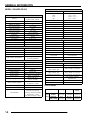
MODEL INFORMATION . . . . . . . . . . . . . . . . . . . . . . . . . . . . . . . . . . . . . . . . . . . . . . . . . . 1.2
MODEL IDENTIFICATION . . . . . . . . . . . . . . . . . . . . . . . . . . . . . . . . . . . . . . . . . . . . . . . . 1.2
ENGINE DESIGNATION NUMBER . . . . . . . . . . . . . . . . . . . . . . . . . . . . . . . . . . . . . . . . . 1.2
VIN IDENTIFICATION . . . . . . . . . . . . . . . . . . . . . . . . . . . . . . . . . . . . . . . . . . . . . . . . . . . 1.2
ENGINE SERIAL NUMBER LOCATION . . . . . . . . . . . . . . . . . . . . . . . . . . . . . . . . . . . . . 1.2
UNIT SERIAL NUMBER (VIN) LOCATION . . . . . . . . . . . . . . . . . . . . . . . . . . . . . . . . . . . 1.3
TRANSMISSION I.D. NUMBER LOCATION . . . . . . . . . . . . . . . . . . . . . . . . . . . . . . . . . . 1.3
VEHICLE DIMENSIONS . . . . . . . . . . . . . . . . . . . . . . . . . . . . . . . . . . . . . . . . . . . . . . . . . . 1.4
VEHICLE DIMENSIONS RANGER 4X4, 6X6. . . . . . . . . . . . . . . . . . . . . . . . . . . . . . . . . . 1.5
GENERAL SPECIFICATIONS. . . . . . . . . . . . . . . . . . . . . . . . . . . . . . . . . . . . . . . . . . . . . . 1.6
MODEL: RANGER XP 4X4 . . . . . . . . . . . . . . . . . . . . . . . . . . . . . . . . . . . . . . . . . . . 1.6
MODEL: RANGER XP 6X6 . . . . . . . . . . . . . . . . . . . . . . . . . . . . . . . . . . . . . . . . . . . 1.6
MODEL: RANGER XP 4X4 . . . . . . . . . . . . . . . . . . . . . . . . . . . . . . . . . . . . . . . . . . . 1.7
MODEL: RANGER XP 6X6 . . . . . . . . . . . . . . . . . . . . . . . . . . . . . . . . . . . . . . . . . . . 1.8
VEHICLE INFORMATION . . . . . . . . . . . . . . . . . . . . . . . . . . . . . . . . . . . . . . . . . . . . . . . . . 1.9
PUBLICATION NUMBERS . . . . . . . . . . . . . . . . . . . . . . . . . . . . . . . . . . . . . . . . . . . . . . . . 1.9
PAINT CODES . . . . . . . . . . . . . . . . . . . . . . . . . . . . . . . . . . . . . . . . . . . . . . . . . . . . . . . . . 1.9
REPLACEMENT KEYS . . . . . . . . . . . . . . . . . . . . . . . . . . . . . . . . . . . . . . . . . . . . . . . . . . 1.9
SPECIAL TOOLS . . . . . . . . . . . . . . . . . . . . . . . . . . . . . . . . . . . . . . . . . . . . . . . . . . . . . . . 1.9
MISC. SPECIFICATIONS AND CHARTS . . . . . . . . . . . . . . . . . . . . . . . . . . . . . . . . . . . . 1.10
CONVERSION TABLE . . . . . . . . . . . . . . . . . . . . . . . . . . . . . . . . . . . . . . . . . . . . . . . . . . 1.10
STANDARD TORQUE SPECIFICATIONS. . . . . . . . . . . . . . . . . . . . . . . . . . . . . . . . . . . 1.11
SAE TAP / DRILL SIZES . . . . . . . . . . . . . . . . . . . . . . . . . . . . . . . . . . . . . . . . . . . . . . . . 1.12
METRIC TAP / DRILL SIZES . . . . . . . . . . . . . . . . . . . . . . . . . . . . . . . . . . . . . . . . . . . . . 1.12
DECIMAL EQUIVALENTS . . . . . . . . . . . . . . . . . . . . . . . . . . . . . . . . . . . . . . . . . . . . . . . 1.12
GLOSSARY OF TERMS. . . . . . . . . . . . . . . . . . . . . . . . . . . . . . . . . . . . . . . . . . . . . . . . . 1.13
1.1
GENERAL INFORMATION
MODEL INFORMATION
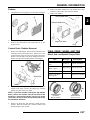
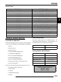
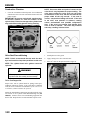
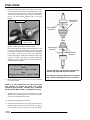
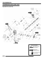
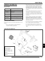
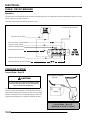
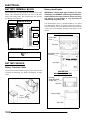
Model Identification
The machine model number must be used with any correspondence regarding warranty or service.
Model
Year
Designation
}
}
}
}
Machine Model Number Identification
R 07 RH 68 AG
Emissions &
Model Option
Basic Chassis
Designation
Engine Designation
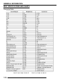
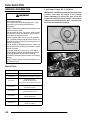
Engine Designation Number
EH068OLE043PLE ............................................................Twin, Liquid Cooled, OHV 4 Stroke, Electric Start
VIN Identification
World
Mfg. ID
Vehicle Identifier
Vehicle Description
Body Style
}
}
1 2 3 4 5 6 7 8 9 10 11 12 13 14 15 16 17
4 X A R H 6 8 A * 7 P 0 0 0 0 0 0
Model
Year
Engine
Emissions
Powertrain
Plant No.
Check Digit
Individual Serial No.
* This could be either
a number or a letter
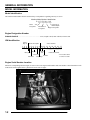
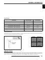
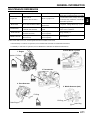
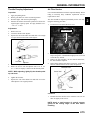
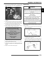
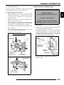
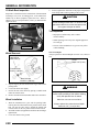
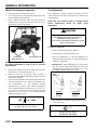
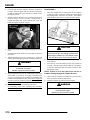
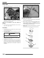
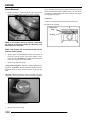
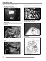
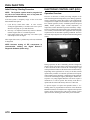
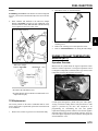
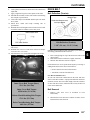
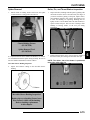
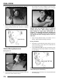
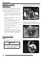
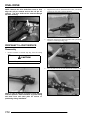
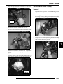
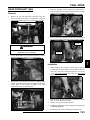
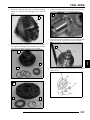
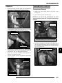
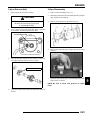
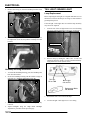
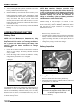
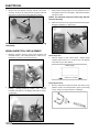
Engine Serial Number Location
Whenever corresponding about an engine, be sure to refer to the engine model number and serial number. This information can be
found on the sticker applied to the cylinder head on the side of engine.
Engine Serial Number
1.2
A
GENERAL INFORMATION
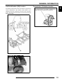
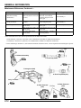
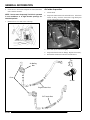
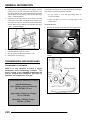
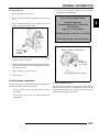
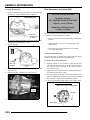
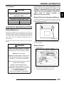
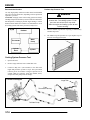
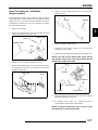
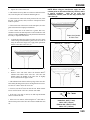
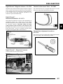
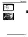
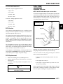
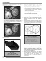
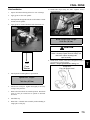
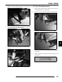
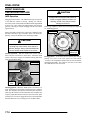
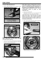
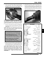
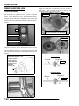
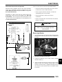
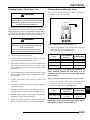
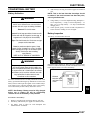
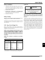
Unit Serial Number (VIN) Location
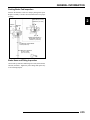
Transmission I.D. Number Location
The machine model number and serial number are important for
vehicle identification. The machine serial number (A) is
stamped on the lower LH frame rail close to the front drive
wheel. The model and serial number are also located on a sticker
under the hood (B).
1
The transmission I.D. number is located on the
right side when installed in the machine.
A
A
A
B
1.3
GENERAL INFORMATION
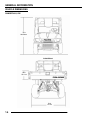
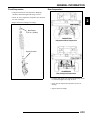
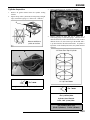
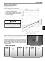
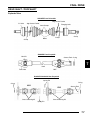
VEHICLE DIMENSIONS
RANGER 4X4, 6X6
75 in.
190.50 cm
RANGER 4x4
10 in.
25.4 cm
58 in.
147 cm
1.4
GENERAL INFORMATION
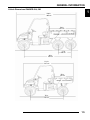
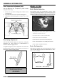
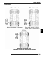
Vehicle Dimensions RANGER 4X4, 6X6
1
120 in.
305 cm
58 in.
147 cm
27 in.
69 cm
90 in.
229 cm
113 in.
287 cm
58 in.
147 cm
76 in.
193 cm
1.5
GENERAL INFORMATION
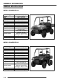
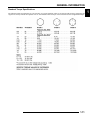
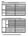
GENERAL SPECIFICATIONS
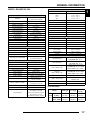
MODEL: RANGER XP 4X4
MODEL NUMBER: R07RH68AD,AG,AH,AK,AL,AW
ENGINE MODEL: EH068OLE
Category
Dimension / Capacity
Length
113 in. / 287 cm
Width
60 in. / 152.4 cm
Height
75 in. / 190.5 cm
Wheel Base
76 in. / 193 cm
Ground Clearance
11.5 in. / (29 cm)
Turning Radius
132 in. / 335 cm
Dry Weight
1185 lbs. / 537 kg
Gross Vehicle Weight
2750 lbs. / 1247 kg
Cargo Box Capacity
1000 lbs. / 454 kg
58 x 42 x 10 in.
Cargo Box Dimensions
(147 x 106.7 x 25.4 cm)
1500 lbs. / 681 kg
Vehicle Payload
(Includes driver and two
passengers - 500 lbs. / 227kg)
Hitch Towing Capacity
1500 lbs. / 681 kg
Hitch Tongue Capacity
150 lbs. / 68 kg
MODEL: RANGER XP 6X6
MODEL NUMBER: R07RF68AF
ENGINE MODEL: EH068OLE
Category
Dimension / Capacity
Length
120 in. / 305 cm
Width
60 in. / 152.4 cm
Height
75 in. / 190.5 cm
Wheel Base
90 in. / 229 cm
Ground Clearance
7.2 in. / (18.25 cm)
Turning Radius
180 in. / 457 cm
Dry Weight
1410 lbs. / 640 kg
Gross Vehicle Weight
2900 lbs. / 1315 kg
Cargo Box Capacity
1250 lbs. / 567 kg
58 x 48 x 10 in.
Cargo Box Dimensions
(147 x 122 x 25.4 cm)
1750 lbs. / 794 kg
Vehicle Payload
(Includes driver and two
passengers - 500 lbs. / 227kg)
Hitch Towing Capacity
1750 lbs. / 794 kg
Hitch Tongue Capacity
150 lbs. / 68 kg
1.6
GENERAL INFORMATION
MODEL: RANGER XP 4X4
MODEL NUMBER: R07RH68AD,AG,AH,AK,AL,AW
ENGINE MODEL: EH068OLE
Engine
Polaris Domestic Twin Cylinder,
Platform
Liquid Cooled, 4-Stroke
Engine Model Number
EH068OLE044
Engine Displacement
683cc
Number of Cylinders
2
Bore & Stroke (mm)
80 x 68 mm
Compression Ratio
9.40:1
Compression Pressure
150-170 psi
Engine Idle Speed
1150 ± 100 RPM
Lubrication
Pressurized Wet Sump
Oil Requirements
0W-40
Oil Capacity
2 qts. / 1.9 L
Coolant Capacity
3.25 qts. / 3.1 L
Overheat Warning
Instrument Cluster Indicator
Exhaust System
2 to 1 Canister Style
Fuel System
Fuel System Type
Bosch Electronic Fuel Injection
Fuel Delivery
Electronic Fuel Pump (in tank)
Fuel Pressure
39 psi
Fuel Filters
See Chapter 4
9 gal. (34 l)
Fuel Capacity / Requirement
87 Octane (minimum)
Electrical
Alternator Max Output
500 watts @ 3000 RPM
Lights: Main Headlights
2 - Dual Beam 35 watts / quartz
Tail
5 watts x 2
Brake
5 watts x 2
Indicator Panel Lights
1 watt (ea.)
Starting System
Electric Start
Ignition System
Bosch EFI (ECU Controlled)
Ignition Timing
7° BTDC @ 1200 RPM
Champion RC7YC3 /
Spark plug / Gap
.035 in. (0.9 mm)
Yuasa YB30L-B /
Battery / Model / Amp Hr
30 Amp Hr. / 12 Volt
Instrument Type
Multifunction Speedometer
DC Outlet
Standard
Fan: 20 Amp
Dash Harness: 20 Amp
Circuit Breakers
Accessory Terminal: 20 Amp
Power Relay: 15 Amp
ECU Battery Supply: 6 Amp
Drivetrain
Transmission Type
Polaris Automatic PVT
Gear Ratio: Front / Rear
High
3.34:1 / 2.89:1
Low
8.67:1 / 7.49:1
Rev
5.92:1 / 5.11:1
Drive Ratio - Front
3.818:1
Drive Ratio - Final
3.70:1
Shift Type
In Line Shift - H / L / N / R
Trans. Oil Requirements
Polaris AGL Gearcase Lube
Belt
3211106
Drive Belt Deflection
1.125” / 28.57 mm
Center Distance
10” / 254.5 mm
Clutch Offset
0.365” / 9.27 mm
Steering / Suspension
Front Suspension
MacPherson Strut
Front Travel
8 in. / 20 cm
Rear Suspension
Independent Rear Suspension
Rear Travel
9 in. / 23 cm
Ground Clearance
11.5 in. / 29 cm
Shock Preload Adjustment
Cam Adjustment
Front / Rear
2-2” Twin Tubes
Turning Radius
132 in. / 335 cm
Toe Out
1/8-1/4 in. / 3-6.35 mm
Wheels / Brakes
12 x 6 / 10 gauge
Front Wheel Size
L.E. Model AW - 14 x 7
12 x 8 / 10 gauge
Rear Wheel Size
L.E. Model AW - 14 x 8
Carlisle / PXT / 26 x 8 R12
Front Tire
L.E. Model AW - Kenda / Radial
Make / Model / Size
Bounty Hunter / 26 x 10 R14
Carlisle / PXT / 26 x 11 R12
Rear Tire
L.E. Model AW - Kenda / Radial
Make / Model / Size
Bounty Hunter / 26 x 12 R14
F/R Tire Air Pressure
8-12 psi Front / 8-12 psi Rear
Foot Actuated - 4 Wheel
Brake - Front / Rear
Hydraulic Disc
Parking Brake
Foot Actuated (Mechanical)
Brake Fluid
DOT 3 or DOT 4
CLUTCH CHART
Altitude
Meters
(Feet)
Shift Weight Drive Spring
Driven
Spring
0-1500
(0-5000)
20-60
(5631698)
Blu/Gray
(7042202)
Blk/Almd
(7043167)
1500-3700
(5000 - 12000)
20-56
(5631215)
Blu/Gray
(7042202)
Blk/Almd
(7043167)
1.7
1
GENERAL INFORMATION
MODEL: RANGER XP 6X6
MODEL NUMBER: R07RF68AF
ENGINE MODEL: EH068OLE
Engine
Polaris Domestic Twin Cylinder,
Platform
Liquid Cooled, 4-Stroke
Engine Model Number
EH068OLE044
Engine Displacement
683cc
Number of Cylinders
2
Bore & Stroke (mm)
80 x 68 mm
Compression Ratio
9.40:1
Compression Pressure
150-170 psi
Engine Idle Speed
1150 ± 100 RPM
Lubrication
Pressurized Wet Sump
Oil Requirements
0W-40
Oil Capacity
2 qts. / 1.9 L
Coolant Capacity
3.25 qts. / 3.1 L
Overheat Warning
Instrument Cluster Indicator
Exhaust System
2 to 1 Canister Style
Fuel System
Fuel System Type
Bosch Electronic Fuel Injection
Fuel Delivery
Electronic Fuel Pump (in tank)
Fuel Pressure
39 psi
Fuel Filters
See Chapter 4
9 gal. (34 l)
Fuel Capacity / Requirement
87 Octane (minimum)
Electrical
Alternator Max Output
500 watts @ 3000 RPM
Lights: Main Headlights
2 - Dual Beam 35 watts / quartz
Tail
5 watts x 2
Brake
5 watts x 2
Indicator Panel Lights
1 watt (ea.)
Starting System
Electric Start
Ignition System
Bosch EFI (ECU Controlled)
Ignition Timing
7° BTDC @ 1200 RPM
Champion RC7YC3 /
Spark plug / Gap
.035 in. (0.9 mm)
Yuasa YB30L-B /
Battery / Model / Amp Hr
30 Amp Hr. / 12 Volt
Instrument Panel Type
Multifunction Speedometer
DC Outlet
Standard
Fan: 20 Amp
Dash Harness: 20 Amp
Circuit Breakers
Accessory Terminal: 20 Amp
Power Relay: 15 Amp
ECU Battery Supply: 6 Amp
1.8
Drivetrain
Transmission Type
Polaris Automatic PVT
Gear Ratio: Front / Rear
High
3.89:1 / 3.36:1
Low
10.08:1 / 8.71:1
Rev
6.87:1 / 5.94:1
Drive Ratio - Front
3.818:1
Drive Ratio - Mid
3.70:1
Drive Ratio - Final
3.70:1
Shift Type
In Line Shift - H / L / N / R
Trans. Oil Requirements
Polaris AGL Gearcase Lube
Belt
3211106
Drive Belt Deflection
1.125” / 28.57 mm
Center Distance
10” / 254.5 mm
Clutch Offset
0.365” / 9.27 mm
Steering / Suspension
Front Suspension
MacPherson Strut
Front Travel
8 in. / 20 cm
Center Suspension
Progressive Rate / Independent
Center Travel
5.25 in. / 13 cm
Rear Suspension
Swing Arm w/Dual Shocks
Rear Travel
6.25 in. / 16 cm
Ground Clearance
7.2 in. / 18.25 cm
Shock Preload Adjustment
Cam Adjustment
Front / Rear
2-2” Twin Tubes
Turning Radius
180 in. / 457 cm
Toe Out
1/8-1/4 in. / 3-6.35 mm
Wheels / Brakes
Front Wheel Size
12 x 6 / 10 gauge
Middle / Rear Wheel Size
12 x 8 / 10 gauge
Front Tire
Titan / AT489 / 25 x 10 R12
Make / Model / Size
Middle / Rear Tire
Titan / AT489 / 25 x 11 R12
Make / Model / Size
F/M/R Tire Air Pressure
8-12 psi Front / 8-12 psi Rear
Foot Actuated - 4 Wheel
Brake - Front / Rear
Hydraulic Disc
Parking Brake
Foot Actuated (Mechanical)
Brake Fluid
DOT 3 or DOT 4
CLUTCH CHART
Altitude
Meters
(Feet)
Shift Weight Drive Spring
Driven
Spring
0-1500
(0-5000)
20-60
(5631698)
Blu/Gray
(7042202)
Blk/Almd
(7043167)
1500-3700
(5000 - 12000)
20-56
(5631215)
Blu/Gray
(7042202)
Blk/Almd
(7043167)
GENERAL INFORMATION
V
1
P
M
20
20
NOTE:
NOTE:
www.purepolaris.com.
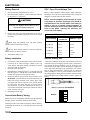
Paint Codes
Painted Part
Color Description
Polaris Number
Frame / Cab
Medium Gloss Black
P-067
RANGER XP 4x4 - Plastic - Hood / Dash
Black Metallic
P-177
RANGER XP 6x6 - Plastic - Hood / Dash
Dark Green
P-195
RANGER XP 4x4 - Plastic - Hood / Dash
Turbo Silver
P-402
RANGER XP 4x4 - Plastic - Hood / Dash
Mossy Oak™
P-455
RANGER XP 4x4 - Plastic - Hood / Dash
Delta Green
P-492
RANGER XP 4x4 - Plastic - Hood / Dash
Sunset Red Metallic
P-520
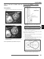
Replacement Keys
Replacement keys can be made from the original key. To identify which series the key is, take the first two digits on the original
key and refer to the chart to the right for the proper part number.
KEY COVER
P/N 5533534
Key Series
Number
Series#
20
21
22
23
27
28
31
32
67
68
Part Number
4010278
4010278
4010321
4010321
4010321
4010321
4110141
4110148
4010278
4010278
SPECIAL TOOLS
Special tools may be required while servicing this vehicle. Some of the tools listed or depicted are mandatory, while other tools
maybe substituted with a similar tool, if available. Polaris recommends the use of Polaris Special Tools when servicing any Polaris
product. Dealers may order special tools through Polaris’ official tool supplier, SPX Corporation, 1-800-328-6657.
1.9
GENERAL INFORMATION
MISC. SPECIFICATIONS AND CHARTS
Conversion Table
°C to °F: 9 (°C + 40) ÷ 5 - 40 = °F
1.10
°F to °C: (°F + 40) ÷ 9 - 40 = °C
GENERAL INFORMATION
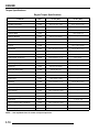
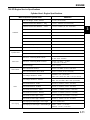
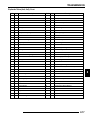
Standard Torque Specifications
The following torque specifications are to be used only as a general guideline. There are exceptions in the steering, suspension, and
engine areas. Always consult the exploded views or each manual section for torque values of fasteners before using standard torque.
1.11
1
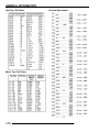
GENERAL INFORMATION
SAE Tap / Drill Sizes
Metric Tap / Drill Sizes
1.12
Decimal Equivalents
GENERAL INFORMATION
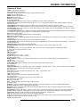
Glossary of Terms
ABDC: After bottom dead center.
ACV: Alternating current voltage.
Alternator: Electrical generator producing voltage alternating current.
ATDC: After top dead center.
BBDC: Before bottom dead center.
BDC: Bottom dead center.
BTDC: Before top dead center.
CC: Cubic centimeters.
Center Distance: Distance between center of crankshaft and center of driven clutch shaft.
Chain Pitch: Distance between chain link pins (No. 35 = 3/8" or 1 cm). Polaris measures chain length in number of pitches.
CI: Cubic inches.
Clutch Buttons: Plastic bushings which aid rotation of the movable sheave in the drive and driven clutch.
Clutch Offset: Drive and driven clutches are offset so that drive belt will stay nearly straight as it moves along the clutch face.
Clutch Weights: Three levers in the drive clutch which relative to their weight, profile and engine RPM cause the drive clutch to
close and grip the drive belt.
Crankshaft Run-Out: Run-out or "bend" of crankshaft measured with a dial indicator while crankshaft is supported between centers
on V blocks or resting in crankcase. Measure at various points especially at PTO.
DCV: Direct current voltage
CVT: Centrifugal Variable Transmission (Drive Clutch System)
DCV: Direct current voltage.
Dial Bore Gauge: A cylinder measuring instrument which uses a dial indicator. Good for showing taper and out-of-round in the
cylinder bore.
Electrical Open: Open circuit. An electrical circuit which isn't complete.
Electrical Short: Short circuit. An electrical circuit which is completed before the current reaches the intended load. (i.e. a bare wire
touching the chassis).
End Seals: Rubber seals at each end of the crankshaft.
Engagement RPM: Engine RPM at which the drive clutch engages to make contact with the drive belt.
ft.: Foot/feet.
Foot Pound: Ft. lb. A force of one pound at the end of a lever one foot in length, applied in a rotational direction.
g: Gram. Unit of weight in the metric system.
gal.: Gallon.
ID: Inside diameter.
in.: Inch/inches.
Inch Pound: In. lb. 12 in. lbs. = 1 ft. lb.
kg/cm²: Kilograms per square centimeter.
kg-m: Kilogram meters.
Kilogram/meter: A force of one kilogram at the end of a lever one meter in length, applied in a rotational direction.
l or ltr: Liter.
lbs/in²: Pounds per square inch.
Left or Right Side: Always referred to based on normal operating position of the driver.
m: Meter/meters.
Mag: Magneto.
Magnetic Induction: As a conductor (coil) is moved through a magnetic field, a voltage will be generated in the windings.
Mechanical energy is converted to electrical energy in the stator.
mi.: Mile/miles.
mm: Millimeter. Unit of length in the metric system. 1 mm = approximately .040".
Nm: Newton meters.
OD: Outside diameter.
Ohm: The unit of electrical resistance opposing current flow.
oz.: Ounce/ounces.
Piston Clearance: Total distance between piston and cylinder wall.
psi.: Pounds per square inch.
PTO: Power take off.
PVT: Polaris Variable Transmission (Drive Clutch system)
qt.: Quart/quarts.
Regulator: Voltage regulator. Regulates battery charging system output at approx. 14.5 DCV as engine RPM increases.
Reservoir Tank: The fill tank in the liquid cooling system.
Resistance: In the mechanical sense, friction or load. In the electrical sense, ohms, resulting in energy conversion to heat.
RPM: Revolutions per minute.
Seized Piston: Galling of the sides of a piston. Usually there is a transfer of aluminum from the piston onto the cylinder wall.
Possible causes: 1) improper lubrication; 2) excessive temperatures; 3) insufficient piston clearance; 4) stuck piston rings.
Stator Plate: The plate mounted under the flywheel supporting the battery charging coils.
TDC: Top dead center. Piston's most outward travel from crankshaft.
Volt: The unit of measure for electrical pressure of electromotive force. Measured by a voltmeter in parallel with the circuit.
Watt: Unit of electrical power. Watts = amperes x volts.
WOT: Wide open throttle.
1.13
1
GENERAL INFORMATION
CHAPTER 2
GENERAL INFORMATION
PERIODIC MAINTENANCE CHART . . . . . . . . . . . . . . . . . . . . . . . . . . . . . . . . . . . . . . . . . 2.3
PERIODIC MAINTENANCE OVERVIEW . . . . . . . . . . . . . . . . . . . . . . . . . . . . . . . . . . . . . 2.3
MAINTENANCE CHART KEY . . . . . . . . . . . . . . . . . . . . . . . . . . . . . . . . . . . . . . . . . . . . . 2.3
PRE-RIDE - 25 HOUR MAINTENANCE INTERVAL . . . . . . . . . . . . . . . . . . . . . . . . . . . . 2.4
50 - 100 HOUR MAINTENANCE INTERVAL . . . . . . . . . . . . . . . . . . . . . . . . . . . . . . . . . . 2.5
100 - 300 HOUR MAINTENANCE INTERVAL . . . . . . . . . . . . . . . . . . . . . . . . . . . . . . . . . 2.6
2
GENERAL COMPONENT LOCATIONS . . . . . . . . . . . . . . . . . . . . . . . . . . . . . . . . . . . . . . 2.7
RH SIDE AND DASH VIEW (4X4) . . . . . . . . . . . . . . . . . . . . . . . . . . . . . . . . . . . . . . . . . . 2.7
LH SIDE AND REAR VIEW (4X4) . . . . . . . . . . . . . . . . . . . . . . . . . . . . . . . . . . . . . . . . . . 2.8
LH SIDE AND RH SIDE VIEWS (6X6) . . . . . . . . . . . . . . . . . . . . . . . . . . . . . . . . . . . . . . . 2.9
SERVICE PRODUCTS AND LUBES. . . . . . . . . . . . . . . . . . . . . . . . . . . . . . . . . . . . . . . . 2.10
POLARIS LUBRICANTS, MAINTENANCE AND SERVICE PRODUCTS . . . . . . . . . . . 2.10
MAINTENANCE REFERENCES . . . . . . . . . . . . . . . . . . . . . . . . . . . . . . . . . . . . . . . . . . . 2.11
MAINTENANCE REFERENCES, CONTINUED. . . . . . . . . . . . . . . . . . . . . . . . . . . . . . . 2.12
GENERAL VEHICLE INSPECTION AND MAINTENANCE. . . . . . . . . . . . . . . . . . . . . . . 2.13
PRE-RIDE / DAILY INSPECTION . . . . . . . . . . . . . . . . . . . . . . . . . . . . . . . . . . . . . . . . . 2.13
FRAME, NUTS, BOLTS, AND FASTENERS . . . . . . . . . . . . . . . . . . . . . . . . . . . . . . . . . 2.13
SHIFT LINKAGE INSPECTION / ADJUSTMENT. . . . . . . . . . . . . . . . . . . . . . . . . . . . . . 2.13
FUEL SYSTEM AND AIR INTAKE . . . . . . . . . . . . . . . . . . . . . . . . . . . . . . . . . . . . . . . . . 2.14
FUEL SYSTEM . . . . . . . . . . . . . . . . . . . . . . . . . . . . . . . . . . . . . . . . . . . . . . . . . . . . . . . . 2.14
FUEL LINES . . . . . . . . . . . . . . . . . . . . . . . . . . . . . . . . . . . . . . . . . . . . . . . . . . . . . . . . . . 2.14
FUEL FILTER . . . . . . . . . . . . . . . . . . . . . . . . . . . . . . . . . . . . . . . . . . . . . . . . . . . . . . . . . 2.14
VENT LINES . . . . . . . . . . . . . . . . . . . . . . . . . . . . . . . . . . . . . . . . . . . . . . . . . . . . . . . . . . 2.14
THROTTLE PEDAL INSPECTION . . . . . . . . . . . . . . . . . . . . . . . . . . . . . . . . . . . . . . . . . 2.14
THROTTLE FREEPLAY ADJUSTMENT . . . . . . . . . . . . . . . . . . . . . . . . . . . . . . . . . . . . 2.15
AIR FILTER SERVICE . . . . . . . . . . . . . . . . . . . . . . . . . . . . . . . . . . . . . . . . . . . . . . . . . . 2.15
AIR INTAKE INSPECTION . . . . . . . . . . . . . . . . . . . . . . . . . . . . . . . . . . . . . . . . . . . . . . . 2.16
ENGINE . . . . . . . . . . . . . . . . . . . . . . . . . . . . . . . . . . . . . . . . . . . . . . . . . . . . . . . . . . . . . . 2.17
COMPRESSION AND LEAKDOWN TEST. . . . . . . . . . . . . . . . . . . . . . . . . . . . . . . . . . . 2.17
BREATHER HOSE INSPECTION . . . . . . . . . . . . . . . . . . . . . . . . . . . . . . . . . . . . . . . . . 2.17
ENGINE OIL LEVEL . . . . . . . . . . . . . . . . . . . . . . . . . . . . . . . . . . . . . . . . . . . . . . . . . . . . 2.17
ENGINE OIL AND FILTER CHANGE . . . . . . . . . . . . . . . . . . . . . . . . . . . . . . . . . . . . . . . 2.18
EXHAUST PIPE . . . . . . . . . . . . . . . . . . . . . . . . . . . . . . . . . . . . . . . . . . . . . . . . . . . . . . . 2.19
TRANSMISSION AND GEARCASES . . . . . . . . . . . . . . . . . . . . . . . . . . . . . . . . . . . . . . . 2.20
TRANSMISSION LUBRICATION . . . . . . . . . . . . . . . . . . . . . . . . . . . . . . . . . . . . . . . . . 2.20
FRONT GEARCASE LUBRICATION (4X4) . . . . . . . . . . . . . . . . . . . . . . . . . . . . . . . . . . 2.21
MIDDLE GEARCASE LUBRICATION (6X6) . . . . . . . . . . . . . . . . . . . . . . . . . . . . . . . . . 2.22
REAR GEARCASE LUBRICATION (4X4) . . . . . . . . . . . . . . . . . . . . . . . . . . . . . . . . . . . 2.23
REAR GEARCASE LUBRICATION (6X6) . . . . . . . . . . . . . . . . . . . . . . . . . . . . . . . . . . . 2.24
COOLING SYSTEM. . . . . . . . . . . . . . . . . . . . . . . . . . . . . . . . . . . . . . . . . . . . . . . . . . . . . 2.25
LIQUID COOLING SYSTEM OVERVIEW . . . . . . . . . . . . . . . . . . . . . . . . . . . . . . . . . . . 2.25
COOLANT LEVEL INSPECTION . . . . . . . . . . . . . . . . . . . . . . . . . . . . . . . . . . . . . . . . . . 2.25
RADIATOR COOLANT LEVEL INSPECTION . . . . . . . . . . . . . . . . . . . . . . . . . . . . . . . . 2.26
COOLANT STRENGTH / TYPE . . . . . . . . . . . . . . . . . . . . . . . . . . . . . . . . . . . . . . . . . . . 2.26
COOLING SYSTEM PRESSURE TEST. . . . . . . . . . . . . . . . . . . . . . . . . . . . . . . . . . . . . 2.26
COOLING SYSTEM HOSES . . . . . . . . . . . . . . . . . . . . . . . . . . . . . . . . . . . . . . . . . . . . . 2.26
RADIATOR . . . . . . . . . . . . . . . . . . . . . . . . . . . . . . . . . . . . . . . . . . . . . . . . . . . . . . . . . . . 2.27
COOLANT DRAIN / RADIATOR REMOVAL . . . . . . . . . . . . . . . . . . . . . . . . . . . . . . . . . 2.27
2.1
GENERAL INFORMATION
FINAL DRIVE / WHEEL AND TIRE . . . . . . . . . . . . . . . . . . . . . . . . . . . . . . . . . . . . . . . . . 2.27
WHEEL, HUB, AND SPINDLE TORQUE TABLE. . . . . . . . . . . . . . . . . . . . . . . . . . . . . . 2.27
CV SHAFT BOOT INSPECTION . . . . . . . . . . . . . . . . . . . . . . . . . . . . . . . . . . . . . . . . . . 2.28
WHEEL REMOVAL . . . . . . . . . . . . . . . . . . . . . . . . . . . . . . . . . . . . . . . . . . . . . . . . . . . . 2.28
WHEEL INSTALLATION . . . . . . . . . . . . . . . . . . . . . . . . . . . . . . . . . . . . . . . . . . . . . . . . 2.28
TIRE INSPECTION. . . . . . . . . . . . . . . . . . . . . . . . . . . . . . . . . . . . . . . . . . . . . . . . . . . . . 2.28
TIRE PRESSURE. . . . . . . . . . . . . . . . . . . . . . . . . . . . . . . . . . . . . . . . . . . . . . . . . . . . . . 2.29
ELECTRICAL AND IGNITION SYSTEM . . . . . . . . . . . . . . . . . . . . . . . . . . . . . . . . . . . . . 2.29
BATTERY MAINTENANCE . . . . . . . . . . . . . . . . . . . . . . . . . . . . . . . . . . . . . . . . . . . . . . 2.29
BATTERY FLUID LEVEL (CONVENTIONAL BATTERY) . . . . . . . . . . . . . . . . . . . . . . . 2.29
BATTERY REMOVAL. . . . . . . . . . . . . . . . . . . . . . . . . . . . . . . . . . . . . . . . . . . . . . . . . . . 2.29
BATTERY INSTALLATION. . . . . . . . . . . . . . . . . . . . . . . . . . . . . . . . . . . . . . . . . . . . . . . 2.30
BATTERY STORAGE. . . . . . . . . . . . . . . . . . . . . . . . . . . . . . . . . . . . . . . . . . . . . . . . . . . 2.30
BATTERY CHARGING. . . . . . . . . . . . . . . . . . . . . . . . . . . . . . . . . . . . . . . . . . . . . . . . . . 2.30
SPARK PLUG SERVICE . . . . . . . . . . . . . . . . . . . . . . . . . . . . . . . . . . . . . . . . . . . . . . . . 2.30
ENGINE TO FRAME GROUND . . . . . . . . . . . . . . . . . . . . . . . . . . . . . . . . . . . . . . . . . . . 2.31
STEERING AND SUSPENSION . . . . . . . . . . . . . . . . . . . . . . . . . . . . . . . . . . . . . . . . . . . 2.31
STEERING . . . . . . . . . . . . . . . . . . . . . . . . . . . . . . . . . . . . . . . . . . . . . . . . . . . . . . . . . . . 2.31
TIE ROD END / STEERING INSPECTION . . . . . . . . . . . . . . . . . . . . . . . . . . . . . . . . . . 2.31
CAMBER AND CASTER . . . . . . . . . . . . . . . . . . . . . . . . . . . . . . . . . . . . . . . . . . . . . . . . 2.31
WHEEL TOE ALIGNMENT INSPECTION . . . . . . . . . . . . . . . . . . . . . . . . . . . . . . . . . . . 2.32
TOE ADJUSTMENT . . . . . . . . . . . . . . . . . . . . . . . . . . . . . . . . . . . . . . . . . . . . . . . . . . . . 2.32
FRONT SUSPENSION. . . . . . . . . . . . . . . . . . . . . . . . . . . . . . . . . . . . . . . . . . . . . . . . . . 2.33
REAR SUSPENSION . . . . . . . . . . . . . . . . . . . . . . . . . . . . . . . . . . . . . . . . . . . . . . . . . . . 2.33
REAR SUSPENSION ADJUSTMENT (4X4) . . . . . . . . . . . . . . . . . . . . . . . . . . . . . . . . . 2.33
REAR SPRING ADJUSTMENT . . . . . . . . . . . . . . . . . . . . . . . . . . . . . . . . . . . . . . . . . . . 2.34
BRAKE SYSTEM. . . . . . . . . . . . . . . . . . . . . . . . . . . . . . . . . . . . . . . . . . . . . . . . . . . . . . . 2.34
BRAKE SYSTEM INSPECTION. . . . . . . . . . . . . . . . . . . . . . . . . . . . . . . . . . . . . . . . . . . 2.34
BRAKE PAD INSPECTION . . . . . . . . . . . . . . . . . . . . . . . . . . . . . . . . . . . . . . . . . . . . . . 2.34
PARKING BRAKE PAD INSPECTION . . . . . . . . . . . . . . . . . . . . . . . . . . . . . . . . . . . . . . 2.35
BRAKE HOSE AND FITTING INSPECTION . . . . . . . . . . . . . . . . . . . . . . . . . . . . . . . . . 2.35
2.2
GENERAL INFORMATION
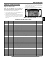
PERIODIC MAINTENANCE CHART
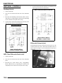
Periodic Maintenance Overview
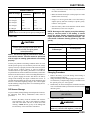
Careful periodic maintenance will help keep your vehicle in the safest, most reliable condition. Inspection, adjustment
and lubrication of important components are explained in the periodic maintenance chart.
Inspect, clean, lubricate, adjust and replace parts as necessary. When inspection reveals the need for replacement
parts, use genuine Polaris parts available from your Polaris dealer.
NOTE: Service and adjustments are critical. If you’re not familiar with safe service and adjustment
procedures, have a qualified dealer perform these operations.
Maintenance intervals in the following chart are based upon average riding conditions and an average vehicle speed of
approximately 10 miles per hour. Vehicles subjected to severe use must be inspected and serviced more frequently.
Severe Use Definition
• Frequent immersion in mud, water or sand
• Racing or race-style high RPM use
• Prolonged low speed, heavy load operation
• Extended idle
• Short trip cold weather operation
Pay special attention to the oil level. A rise in oil level during cold weather can indicate contaminants collecting in the
oil sump or crankcase. Change oil immediately if the oil level begins to rise. Monitor the oil level, and if it continues to
rise, discontinue use and determine the cause or see your dealer.
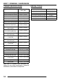
Maintenance Chart Key
The following symbols denote potential items to be aware of during maintenance:
= CAUTION: Due to the nature of these adjustments, it is recommended this service be performed by an
authorized Polaris dealer.
= SEVERE USE ITEM --If vehicle is subjected to severe use, decrease interval by 50%
(Severe Use is defined as frequent vehicle immersion in mud, water or sand, racing or race-style high rpm
use, prolonged low speed - heavy load operation or extended idle. More preventative maintenance is required
under these conditions. Fluid changes, cable, chain and chassis lubrication are required more frequently. For
engine oil, short trip cold weather riding also constitutes severe use. Pay special attention to oil level. A rising
oil level in cold weather can indicate contaminants collecting in the oil sump or crankcase. Change oil immediately and monitor level. If oil level begins to rise, discontinue use and determine cause.)
E= Emission Control System Service (California).
NOTE: Inspection may reveal the need for replacement parts. Always use genuine Polaris parts.
WARNING
Improperly performing the procedures marked with a could
result in component failure and lead to serious injury or death.
Have an authorized Polaris dealer perform these services.
2.3
2
GENERAL INFORMATION
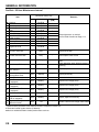
Pre-Ride - 25 Hour Maintenance Interval
Item
Steering
Front Suspension
Rear Suspension
Tires
Maintenance Interval
(whichever comes first)
Miles
Hours
Calendar
(KM)
Pre-Ride
-
Pre-Ride
-
-
Pre-Ride
-
-
Pre-Ride
-
Remarks
Brake Fluid Level
Brake Pedal Travel
-
Pre-Ride
-
-
Pre-Ride
-
Brake Systems
Wheels / Fasteners
Frame Fasteners
-
Pre-Ride
Pre-Ride
Pre-Ride
-
Engine Oil Level
-
Pre-Ride
-
Air Filter / Pre-Filter
-
Daily
-
Inspect;clean often
Air Box Sediment Tube
-
Daily
-
Drain deposits when visible
Coolant Level
-
Daily
-
Head Lamp / Tail Lamp
-
Daily
-
-
Weekly
-
Inspect; replace as needed
10 H
Monthly
-
Inspect periodically
20 H
Monthly
-
Check terminals; clean; test
25 H
Monthly
-
Inspect level; change yearly
25 H
Monthly
-
Inspect level; change yearly
25 H
Monthly
-
Inspect level; change yearly
25 H
Monthly
-
Inspect level; change yearly
25 H
Monthly
-
Inspect; replace if necessary
25 H
1M
-
Perform a break-in oil change at one month
E
E
E
Air Filter,
E
Main Element
Brake Pad Wear / Inspect
Parking Brake Pads
Battery
Front Gearcase Oil
(if equipped)
Middle Gearcase Oil
(if equipped)
Rear Gearcase Oil
(if equipped)
Transmission Oil
Engine Breather
E Filter (if equipped)
Engine Oil Change
E
(Break-In Period)
Make adjustments as needed.
See Pre-Ride Checklist on Page 2.13.
Check level daily, change coolant every 2
years
Check operation; apply dielectric grease if
replacing
Perform these procedures more often for vehicles subjected to severe use.
E Emission Control System Service (California)
Have an authorized Polaris dealer perform these services.
2.4
GENERAL INFORMATION
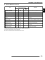
50 - 100 Hour Maintenance Interval
Item
Maintenance Interval
(whichever comes first)
Miles
Hours
Calendar
(KM)
Remarks
50 H
6M
-
Lubricate all grease fittings, pivots, cables,
etc.
Inspect, lubricate, adjust
Steering
50 H
6M
-
Lubricate
Front Suspension
Rear Suspension
50 H
6M
-
Lubricate
50 H
6M
-
50 H
6M
-
Lubricate
Inspect; adjust; lubricate; replace if
necessary
50 H
6M
-
Inspect ducts for proper sealing/air leaks
50 H
6M
-
Cooling System
50 H
6M
-
Engine Oil Change
100 H
6M
-
Inspect; adjust; replace as needed
Inspect coolant strength seasonally;
pressure test system yearly
Perform a break-in oil change at 25 hours/
one month
Oil Filter Change
100 H
6M
-
General Lubrication
Shift Linkage
Throttle Cable / Throttle
E Pedal
Throttle Body Air Intake
E
Ducts / Flange
Drive Belt
E
E
50 H
3M
-
Replace with oil change
Perform these procedures more often for vehicles subjected to severe use.
E Emission Control System Service (California)
Have an authorized Polaris dealer perform these services.
2.5
2
GENERAL INFORMATION
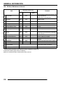
100 - 300 Hour Maintenance Interval
Item
Maintenance Interval
(whichever comes first)
Miles
Hours
Calendar
(Km)
Remarks
Fuel System
E
100 H
12M
-
Check for leaks at tank cap, fuel lines, fuel
pump, and fuel rail.
Replace lines every two years.
Fuel Filter
E
100 H
12M
-
Replace yearly
Radiator
Cooling Hoses
Engine Mounts
100 H
12M
-
Inspect; clean external surfaces
100 H
12M
-
Inspect for leaks
100 H
12M
-
Inspect
100 H
12M
-
Inspect
100 H
12M
-
Inspect; replace as needed
100 H
12M
-
Clutches (Drive and Driven) 100 H
Front Wheel Bearings
100 H
12M
12M
-
24M
36M
-
Exhaust Muffler / Pipe
Spark Plug
E
Wiring
Toe Adjustment
100 H
Brake Fluid
Spark Arrestor
200 H
300 H
Auxiliary Brake
Headlight Aim
Inspect for wear, routing, security; apply
dielectric grease to connectors subjected to
water, mud, etc.
Inspect;clean; replace worn parts
Inspect; replace as needed
Inspect periodically; adjust when parts are
replaced
Change every two years (DOT 3 or DOT 4)
Clean out
-
Inspect daily; adjust as needed
-
Adjust as needed
Perform these procedures more often for vehicles subjected to severe use.
E Emission Control System Service (California)
Have an authorized Polaris dealer perform these services.
2.6
GENERAL INFORMATION
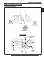
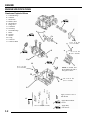
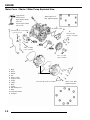
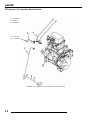
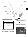
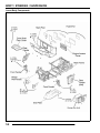
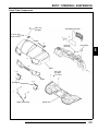
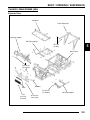
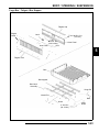
GENERAL COMPONENT LOCATIONS
RH Side (4X4) and Dash View
2
Rear Gearcase
Gas Tank
Front Gearcase
(Behind Radiator)
Engine (under seat)
Dash Components
Instrument
Cluster
Cup
Holder
Light
Switch
AWD / Differential Switch
(if equipped)
Cup
Holder
Storage
Box
Ignition
Switch
Storage
Tray
12V
Accessory
Outlet
Mode
Button
Storage
Compartment
(with lid)
2.7
GENERAL INFORMATION
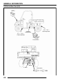
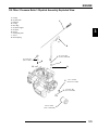
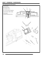
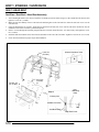
LH Side and Rear View (4X4)
Battery
Storage
Compartment
Rear Prop Shaft
Front Prop Shaft
Transmission
Tail Gate Latch
Air Cleaner
Muffler
2" Hitch
2.8
Drive Shafts
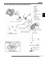
GENERAL INFORMATION
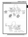
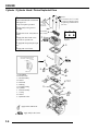
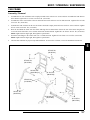
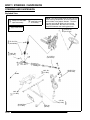
LH Side and RH Side Views (6X6)
2
Front Gearcase
(behind radiator)
Engine (under seat)
Rear Gearcase
Transmission
Mid Gearcase
Battery
Drive Shafts
Front Prop Shaft
Rear Prop Shaft
2.9
GENERAL INFORMATION
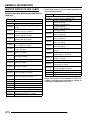
SERVICE PRODUCTS AND LUBES
Polaris Lubricants, Maintenance and Service
Products
Part No.
Description
Engine Lubricant
2870791 Fogging Oil (12 oz. Aerosol)
Premium 2 Cycle Engine Oil (Quart) (12
2871098
Count)
Engine Oil (Quart) Premium 4 Synthetic
2871281
0W-40 (4-Cycle) (12 Count)
Engine Oil (Gallon) Premium 4 Synthetic
2871844
0W-40 (4-Cycle) (4 Count)
Engine Oil (16 Gallon) Premium 4
2871567
Synthetic 0W-40 (4-Cycle)
Gearcase / Transmission Lubricants
Premium Synthetic AGL Gearcase Lube
2873602
(12 oz. bottle) (12 Count)
Premium Synthetic AGL Gearcase Lube
2873603
(1 Gal.) (4 Count)
Premium ATV Angle Drive Fluid
2871653
(8 oz.) (12 Count)
Premium ATV Angle Drive Fluid
2872276
(2.5 Gal) (2 Count)
2870465 Oil Pump for 1 Gallon Jug
Premium Demand Drive Hub Fluid
2871654
(8 oz.) (12 Count)
Premium Demand Drive Hub Fluid
2872277
(2.5 gal.) (2 Count)
Grease / Specialized Lubricants
Premium All Season Grease
2871322
(3 oz. cartridge) (24 Count)
Premium All Season Grease
2871423
(14 oz. cartridge) (10 Count)
2871460 Starter Drive Grease (12 Count)
2871515 Premium U-Joint Lube (3 oz.) (24 Count)
2871551 Premium U-Joint Lube (14 oz.) (10 Count)
2871312 Grease Gun Kit
2871329 Dielectric Grease (Nyogel™)
Coolant
2871323 60/40 Coolant (Gallon) (6 Count)
2871534 60/40 Coolant (Quart) (12 Count)
2.10
NOTE: Each item can be purchased separately at
your local Polaris dealer.
Part No.
Description
Additives / Sealants / Thread Locking Agents / Misc.
2870585 Loctite™ Primer N, Aerosol, 25 g
Loctite™ Thread Sealant 565
2871956
(50 ml.) (6 Count)
Loctite™ Threadlock 242
2871949
(50 ml.) (10 Count)
Loctite™ Threadlock 242
2871950
(6 ml.) (12 Count)
Loctite™ Threadlock 262
2871951
(50 ml.) (10 Count)
Loctite™ Threadlock 262
2871952
(6 ml.) (12 Count)
Loctite™ Threadlock 271
2871953
(6 ml.) (12 Count)
Loctite™ Threadlock 271
2871954
(36 ml.) (6 Count)
Loctite™ 680-Retaining Compound
2870584
(10 ml.)
Loctite™ 518 Gasket Eliminator / Flange
2870587
Sealant (50 ml.) (10 Count)
Premium Carbon Clean
2871326
(12 oz.) (12 Count)
2870652 Fuel Stabilizer (16 oz.) (12 Count)
Black RTV Silicone Sealer
2871957
(3 oz. tube) (12 Count)
Black RTV Silicone Sealer
2871958
(11 oz. cartridge) (12 Count)
2870990 DOT 3 Brake Fluid (12 Count)
2871557 Crankcase Sealant, 3-Bond 1215 (5oz.)
2872893 Engine Degreaser (12oz.) (12 Count)
NOTE: The number count indicated by each part
number in the table above indicates the number of
units that are shipped with each order.
GENERAL INFORMATION
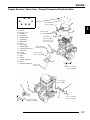
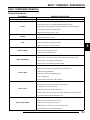
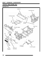
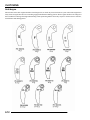
MAINTENANCE REFERENCES
Item
Lube Rec.
1. Engine Oil
Polaris 0W-40
Synthetic (PN 2871281)
2. Brake Fluid
DOT 3 (PN 2870990) or Dot 4
3. Transmission
4. Front Gearcase
5. Middle Gearcase
Polaris AGL Gearcase
Lubricant (PN 2873602)
Polaris Demand Drive Hub
Fluid (PN 2871654)
ATV Angle Drive Fluid
(PN 2871653)
Method
Frequency*
Change after 1st month (25 hrs), 6 months
or 100 hours thereafter; Change more often
in extremely dirty conditions, or short trip
cold weather operation.
Add oil to proper level.
Fill reservoir between MAX
and Min lines.
Add lube to bottom of fill plug
threads.
Drain completely. Add lube to
specified quantity.
Drain completely. Add lube to
specified quantity.
As required. Change fluid every 2 years.
Change annually. Change more often if
used in severe conditions.
Change annually***
Semi-annually**
* More often under severe use, such as operated in water or under severe loads.
**Semi-annually or 50 hours of operation (refer to Maintenance Schedule for additional information)
***Annually or 100 hours of operation (refer to Maintenance Schedule for additional information)
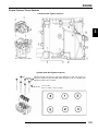
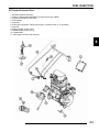
2. Brake Master Cylinder
1. Engine
Dipstick / Fill Tube
3. Transmission
4. Front Gearcase
5. Middle Gearcase (6x6)
Fill Plug
Drain Plug
Fill Plug
Drain Plug
2.11
2
GENERAL INFORMATION
Maintenance References, Continued.....
Item
Lube Rec.
6. Hubstrut Assembly
(Both Sides)
7. Swing Arm Pivot
8. Rear Prop Shaft Yoke
9. Front Prop Shaft Yoke
10. Rear Gearcase
Polaris All Season Grease (PN
2871423)
Polaris All Season Grease (PN
2871423)
Polaris Premium U-Joint Lube
(PN 2871551)
Polaris Premium U-Joint Lube
(PN 2871551)
ATV Angle Drive Fluid
(PN 2871653)
Method
Locate grease fitting on the
underside of the hubstrut
assembly and grease with
grease gun.
Locate grease fitting on inside
of the swing arm pivot.
Locate fittings and grease with
grease gun.
Locate fittings and grease with
grease gun.
Drain completely. Add lube to
specified quantity.
Frequency*
Semi-annually**
Semi-annually**
Semi-annually**
Semi-annually**
Change annually***
* More often under severe use, such as operated in water or under severe loads.
**Semi-annually or 50 hours of operation (refer to Maintenance Schedule for additional information)
***Annually or 100 hours of operation (refer to Maintenance Schedule for additional information)
Grease conforming to NLGI No. 2, such as Polaris Premium All Season Grease, Conoco Superlube M or Mobilegrease Special
Yoke
6. Hubstrut Assembly
9. Front Prop Shaft
Yoke
7. Swing Arm (6x6)
8. Rear Prop Shaft (6x6)
Swing Arm Pivot
10. Rear Gearcase
(6x6)
2.12
Fill Plug
10. Rear Gearcase
(4x4)
GENERAL INFORMATION
GENERAL VEHICLE INSPECTION
AND MAINTENANCE
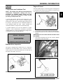
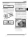
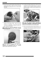
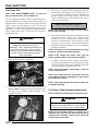
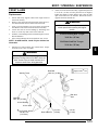
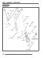
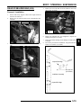
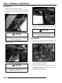
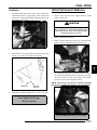
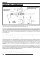
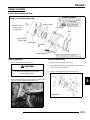
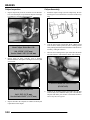
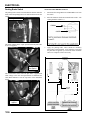
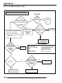
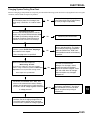
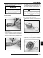
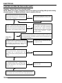
Shift Linkage Inspection / Adjustment
Linkage rod adjustment is necessary when symptoms include:
Pre-Ride / Daily Inspection
• No All Wheel Drive light
Perform the following pre-ride inspection daily, and when
servicing the vehicle at each scheduled maintenance.
• Noise on deceleration
2
• Inability to engage a gear
• Tires - check condition and pressures
• Excessive gear clash (noise)
• Fuel and oil tanks - fill both tanks to their proper level;
Do not overfill oil tank
• Shift selectors moving out of desired range
• All brakes - check operation and adjustment (includes
auxiliary brake)
NOTE: Remove necessary components to gain
access to shift linkage cable ends (i.e. exhaust heat
shield, exhaust pipe, etc.)
• Throttle - check for free operation and closing
• Headlight/Taillight/Brakelight - check operation of all
indicator lights and switches
• Engine stop switch - check for proper function
• Wheels - check for tightness of wheel nuts and axle
nuts; check to be sure axle nuts are secured by cotter
pins
• Air cleaner element - check for dirt; clean or replace
• Steering - check for free operation noting any unusual
looseness in any area
1.
• Loose parts - visually inspect vehicle for any damaged
or loose nuts, bolts or fasteners
2.
3.
• Engine coolant - check for proper level at the recovery
bottle
4.
• Check all rear suspension components for wear or
damage.
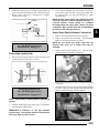
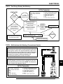
Inspect shift linkage cable, clevis pins, and pivot bushings
and replace if worn or damaged.
Be sure idle speed is adjusted properly.
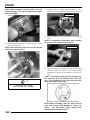
Place gear selector in neutral. Make sure the transmission
bell crank is engaged in the neutral position detents.
With two wrenches loosen the outside jam nut
counterclockwise. Turn the outside jam nut 1 1/2 turns.
Perform this procedure on the shift lever end, also.
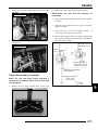
Inside Jam Nut
Outside Jam Nut
Frame, Nuts, Bolts, and Fasteners
Periodically inspect the torque of all fasteners in accordance
with the maintenance schedule. Check that all cotter pins are in
place. Refer to specific fastener torques listed in each chapter.
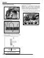
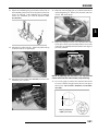
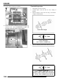
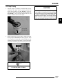
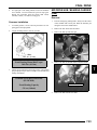
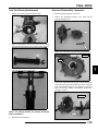
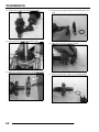
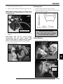
Shift Cable Adjustment
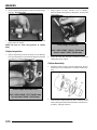
5.
6.
After turning the outside jam nut 1 1/2 turns. Hold the
outside jam nut with a wrench and tighten the inside jam
nut clockwise, until it is tight against the bracket.
Repeat Step 4 and Step 5 until the proper adjustment is
made for the transmission cable.
2.13
GENERAL INFORMATION
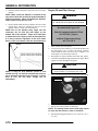
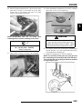
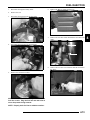
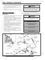
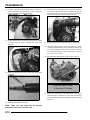
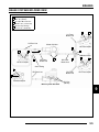
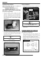
7.
Use this procedure to loosen or tighten the shift linkage
cable as needed.
Clockwise
Counterclockwise
Inside Jam Nut
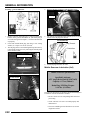
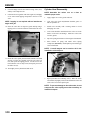
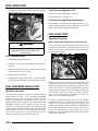
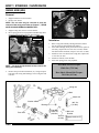
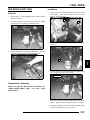
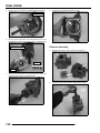
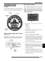
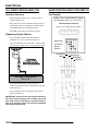
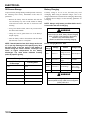
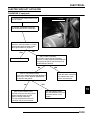
Fuel Filter
The RANGER XP 4x4 and 6x6 EFI engines use a nonserviceable, high-volume, high-pressure, 60-micron internal
fuel pump filter and an internal 10-micron filter located before
the pump regulator. Neither filter is servicable.
Outside Jam Nut
Fuel filter in tank is not serviceable
FUEL SYSTEM AND AIR INTAKE
Fuel System
NOTE: For all other information related to the EFI
fuel system refer to Chapter 4.
WARNING
Gasoline is extremely flammable and explosive
under certain conditions.
Always stop the engine and refuel outdoors or in
a well ventilated area.
Do not smoke or allow open flames or sparks in
or near the area where refueling is performed or
where gasoline is stored.
Do not overfill the tank. Do not fill the tank neck.
If you get gasoline in your eyes or if you swallow
gasoline, seek medical attention immediately.
If you spill gasoline on your skin or clothing,
immediately wash it off with soap and water
and change clothing.
Never start the engine or let it run in an enclosed
area. Engine exhaust fumes are poisonous and
can result loss of consciousness or death
in a short time.
Never drain the fuel when the engine is hot.
Severe burns may result.
Vent Lines
1.
2.
Check fuel tank and transmission vent lines for signs of
wear, deterioration, damage or leakage. Replace every
two years.
Be sure vent lines are routed properly and secured with
cable ties. CAUTION: Make sure lines are not kinked or
pinched
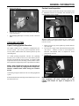
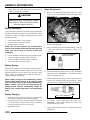
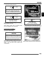
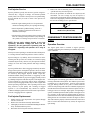
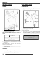
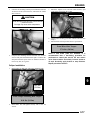
Throttle Pedal Inspection
Throttle Pedal
Fuel Lines
1.
2.
3.
Check fuel lines for signs of wear, deterioration, damage
or leakage. Replace if necessary.
Be sure fuel lines are routed properly and secured with
cable ties. CAUTION: Make sure lines are not kinked or
pinched.
Replace all fuel lines every two years.
2.14
If the throttle pedal has excessive play due to cable stretch or
cable misadjustment, it will cause a delay in throttle speed.
Also, the throttle may not open fully. If the throttle pedal has no
play, the throttle may be hard to control, and the idle speed may
be erratic.
Check the throttle pedal play periodically in accordance with the
Periodic Maintenance Chart and adjust the play if necessary.
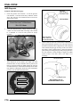
GENERAL INFORMATION
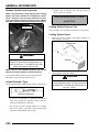
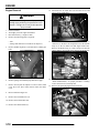
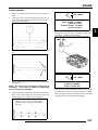
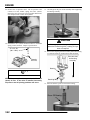
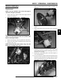
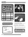
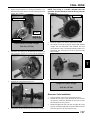
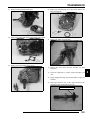
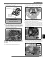
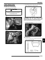
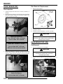
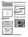
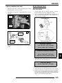
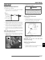
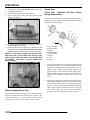
Throttle Freeplay Adjustment
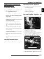
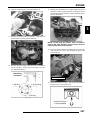
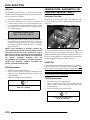
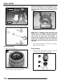
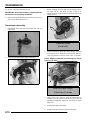
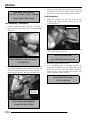
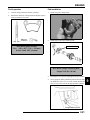
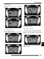
Air Filter Service
Inspection
It is recommended that the air filter be replaced annually. When
riding in extremely dusty conditions replacement will be
required more often.
1.
2.
3.
4.
Apply the parking brake.
Put the gear shift lever in the N (Neutral) position.
Start the engine, and warm it up thoroughly.
Measure the distance the throttle pedal moves before the
engine begins to pick up speed. Free play should be 1/16”
- 1/8” (1.5 - 3 mm).
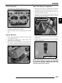
The filter should be inspected periodically before each ride,
using the following procedure.
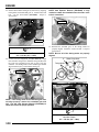
1.
Lift the box to access the filter box cover.
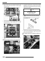
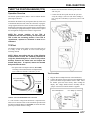
Adjustment
1.
2.
3.
Air Box Location
Remove the seat.
Locate the throttle cable adjuster.
Squeeze the end of the rubber boot and slide it far enough
to expose the end of the inline cable adjuster.
Boot
2.
3.
Lock Nut
4.
5.
Adjuster
4.
Loosen the adjuster lock nut.
Rotate the boot to turn the adjuster until 1/16" to 1/8"
(1.5 - 3 mm) of freeplay is achieved at the throttle pedal.
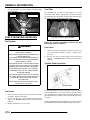
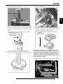
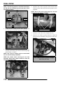
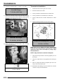
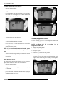
Breather Filter
Cover Seal
NOTE: While adjusting, lightly flip the throttle pedal
up and down.
6.
7.
Remove clips (2) from air box cover and remove cover.
Inspect the gasket. It should adhere tightly to the cover and
seal all the way around.
Remove air filter assembly. Do not clean the main filter,
the filter should be replaced.
Inspect main element and replace if necessary. If the filter
has been soaked with fuel or oil it must be replaced.
Tighten the lock nut.
Squeeze the end of the rubber boot and slide it over the
cable adjuster to its original position.
Filter
Cover
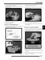
Installation
1.
Reinstall the filter into the air box container. Be sure the
filter fits tightly in the air box.
NOTE: Apply a small amount of general purpose
grease to the sealing edges of the filter before
installing.
2.15
2
GENERAL INFORMATION
2.
Check air box. If oil or water deposits are found, drain them
into a suitable container.
NOTE: Service more frequently if vehicle is operated
in wet conditions or at high throttle openings for
extended periods.
3.
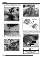
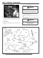
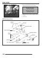
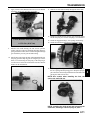
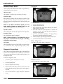
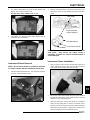
Air Intake Inspection
1.
Lift the hood.
2.
Inspect the foam inserts in the air baffle boxes. If the foam
inserts are dirty, clean the foam with a high flash point
solvent, followed by hot soapy water.
3.
Rinse and dry the foam thoroughly.
4.
Inspect the foam for tears or damage. Replace if necessary.
5.
Reinstall the foam inserts into the air baffle boxes.
Install air box cover and secure with clips.
Air Baffing
Box
Foam
Air Box
Engine Intake Duct
PVT Intake Duct
2.16
GENERAL INFORMATION
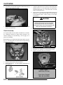
ENGINE
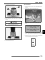
Engine Oil Level
Compression and Leakdown Test
The twin cylinder engine is a wet-sump engine, meaning the oil
is contained in the bottom of the crankcase. To check the oil
level follow the procedure listed below.
NOTE: This engine does NOT have decompression
components. Compression readings will vary in
proportion to cranking speed during the test.
Average compression (measured) is about 150-200
psi during a compression test.
2
A smooth idle generally indicates good compression. Low
engine compression is rarely a factor in running condition
problems above idle speed. Abnormally high compression can
be caused by carbon deposits in the combustion chamber or
worn, damaged exhaust cam lobes. Inspect camshaft and
combustion chamber if compression is abnormally high.
A cylinder leakdown test is the best indication of engine
condition. Follow manufacturer's instructions to perform a
cylinder leakage test. (Never use high pressure leakage testers,
as crankshaft seals may dislodge and leak).
Cylinder Compression
Standard: 150-200 PSI
Cylinder Leakdown
Service Limit 15%
Dipstick
1.
2.
Set machine on a level surface and set the parking brake.
Be sure the machine has sat for awhile before removing the
dipstick.
IMPORTANT: Do not run the machine and then check
the dipstick.
3. Stop engine and unlock the lever lock. Remove dipstick
and wipe dry with a clean cloth.
(Inspect for cause if test exceeds 15%)
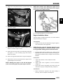
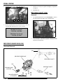
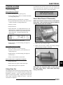
Breather Hose Inspection
The engine is equipped with a breather hose (A). Inspect the
breather hose for possible kinks or wear. The hose is form fitted for a proper fit. Follow the breather hose from the side of
the airbox to the engine valve cover.
Lever Lock
Dipstick
NOTE: Make sure lines are not kinked or pinched.
2.17
GENERAL INFORMATION
4.
Reinstall dipstick and push it into place. Do not lock the
dipstick.
NOTE: Make certain the dipstick is inserted all the
way into the filler tube to keep the angle and depth of
dipstick consistent. When reinstalling the dipstick,
make certain to seat the lever lock.
Engine Oil and Filter Change
WARNING
Personal injury can occur when handling used
oil. Hot oil can cause burns or skin damage.
5.
Remove dipstick and check to see that the oil level is in the
normal range. Add oil as indicated by the level on the
dipstick. Do not overfill. (See NOTE below!)
NOTE: Due to the dipstick entry angle into the
crankcase, the oil level will read higher on the
bottom side of the dipstick. Proper level indication
is determined on the upper surface of the dipstick as
it is being removed, regardless of the level marks
being on top or on bottom. (See the next illustration)
Recommended Engine Oil:
Polaris Premium Synthetic OW-40
(PN 2871281) (Quart)
Ambient Temperature Range
-40° F to 120° F
Dipstick
1.
2.
Always read top side of dipstick to
properly check oil level in crankcase
3.
4.
Place vehicle on a level surface.
To ease access to the oil filter, try to access the oil filter from
the front engine cover or remove the storage container
located under the driver side seat (refer to Chapter 5 for
front engine cover and storage removal).
Run engine two to three minutes until warm. Stop engine.
Clean area around drain plug at bottom of oil engine. Drain
plug is accessible through the skid plate.
CAUTION
NOTE: A rising oil level between checks
weather driving can indicate contaminants
gas or moisture collecting in the crankcase.
level is over the full mark, change
immediately.
in cool
such as
If the oil
the oil
Oil may be hot. Do not allow hot oil to come into
contact with skin, as serious burns may result.
5.
Place a drain pan beneath crankcase and remove drain plug.
Drain Plug
6. Allow oil to drain completely.
7. Replace the sealing washer on drain plug.
NOTE: The sealing surface on the drain plug should
be clean and free of burrs, nicks or scratches.
8.
2.18
Reinstall drain plug and torque to 192 ± 24 in. lbs. (21.7 ±
2.7 Nm).
GENERAL INFORMATION
9.
Place shop towels beneath oil filter. Using Oil Filter
Wrench (PV-43527), turn filter counterclockwise to
remove.
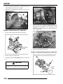
Exhaust Pipe
WARNING
Oil Filter
10. Using a clean dry cloth, clean filter sealing surface on
crankcase.
11. Lubricate O-ring on new filter with a film of fresh engine
oil. Check to make sure the O-ring is in good condition.
12. Install new filter and turn by hand until filter gasket contacts
the sealing surface, then turn an additional 1/2 turn.
13. Remove dipstick and fill sump with 2 quarts (1.9 l) of
Polaris Premium 4 Synthetic Oil (PN2871281)
Do not perform clean out immediately after the engine
has been run, as the exhaust system becomes very hot.
Serious burns could result from contact with exhaust
components.
To reduce fire hazard, make sure that there are no
combustible materials in the area when purging the
spark arrestor.
Wear eye protection.
Do not stand behind or in front of the vehicle while
purging the carbon from the spark arrestor.
Never run the engine in an enclosed area. Exhaust
contains poisonous carbon monoxide gas.
Do not go under the machine while it is inclined. Set the
hand brake and block the wheels to prevent roll back.
Failure to heed these warnings could result in serious
personal injury or death.
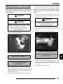
The exhaust pipe must be periodically purged of accumulated
carbon as follows:
1.
Crankcase Drain Plug Torque:
192 ± 24 in. lbs. (21.7 ± 2.7 Nm)
Oil Filter Torque:
Turn by hand until filter gasket contacts
sealing surface, then turn an
additional 1/2 turn
Oil Filter Wrench:
(PV-43527)
Clean Out Plug
2.
3.
14. Place gear selector in neutral and set parking brake.
15. Start the engine and let it idle for one to two minutes.
Stop the engine and inspect for leaks.
16. Re-check the oil level on the dipstick and add oil as
necessary to bring the level to the upper mark on the
dipstick.
17. Dispose of used oil and oil filter properly.
Remove the clean out plugs located on the bottom of the
muffler as shown below.
Place the transmission in Park and start the engine. Purge
accumulated carbon from the system by momentarily
revving the engine several times.
If some carbon is expelled, cover the exhaust outlet and
lightly tap on the pipe around the clean out plugs with a
rubber mallet while revving the engine several more times.
2.19
2
GENERAL INFORMATION
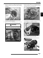
4.
5.
If particles are still suspected to be in the muffler, back the
machine onto an incline so the rear of the machine is one
foot higher than the front. Set the hand brake and block the
wheels. Make sure the machine is in Park and repeat Steps
2 and 3. SEE WARNING
If particles are still suspected to be in the muffler, drive the
machine onto the incline so the front of the machine is one
foot higher than the rear. Set the hand brake and block the
wheels. Make sure the machine is in Park and repeat Steps
2 and 3. SEE WARNING
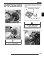
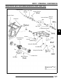
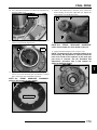
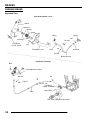
The transmission lubricant level should be checked and changed
in accordance with the maintenance schedule.
• Be sure vehicle is level with the parking brake on
before proceeding.
• Check vent hose to be sure it is routed properly and
unobstructed.
To check the level:
1.
Remove the fill plug on the backside of the transmission.
Fill Plug
1 ft.
6.
7.
8.
Repeat steps 2 through 5 until no more particles are
expelled when the engine is revved.
Stop the engine and allow the arrestor to cool.
Reinstall the clean out plugs.
2.
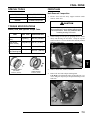
The fluid should be at the bottom of the fill plug hole
threads.
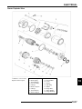
Figure 7-26
TRANSMISSION AND GEARCASES
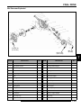
Transmission Lubrication
NOTE: It is very important to follow a regular
transmission fluid check/change schedule. The
service manual of the RANGER recommends the
level be checked every twenty-five (25) hours of
operation, and changed once (1) a year.
TRANSMISSION SPECIFICATIONS
Specified Lubricant:
AGL Synthetic Gearcase Lubricant
(PN 2873602) (32 oz.)
Approximate Capacity at Change:
15.2 oz. (450 ml.)
Drain Plug / Fill Plug Torque:
14 ft. lbs. (19 Nm)
2.20
Fill Plug Threads
Proper
Fluid
Level
GENERAL INFORMATION
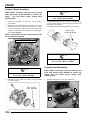
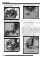
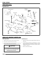
To change lubricant:
1.
Remove skid plate (if necessary).
2.
Place a drain pan beneath the transmission oil drain plug
area.
3.
Remove the drain plug and wipe the magnetic end clean to
remove accumulated metallic filings.
TRANSMISSION
• The correct front gearcase lubricant to use is Polaris
Premium Demand Hub Fluid.
Front Gearcase Specifications
2
Specified Lubricant:
Premium Demand Drive Hub Fluid
(PN 2871654)
Capacity: 5.0 oz. (150 ml.)
Fill Plug Torque: 8-30 ft. lbs. (11-41 Nm)
Drain Plug Torque: 10 ft. lbs. (14 Nm)
FRONT GEARCASE
Drain Plug
14 ft. lbs.
(19 Nm)
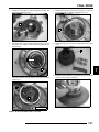
4.
Make sure vent is unobstructed
After the oil has drained completely, install the drain plug.
Torque to 14 ft. lbs. (19 Nm).
5.
Add the proper lubricant through the fill plug hole until the
oil level is at the bottom of the fill plug threads (see figure
7-26). Do not overfill.
6.
Torque fill plug to 14 ft. lbs. (19 Nm)
7.
Check for leaks.
Fill Plug
8-30 ft. lbs.
(11-41 Nm)
Drain Plug: 10 ft. lbs. (14 Nm)
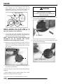
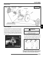
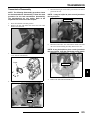
Front Gearcase Lubrication
To check the lubricant level:
The gearcase lubricant level should be checked and changed in
accordance with the maintenance schedule.
• Be sure vehicle is level with parking brake on before
proceeding.
The front gearcase lubricant level cannot be checked with a
dipstick. The gearcase must be drained and re-filled with the
proper amount of lubricant or be filled to the bottom of the fill
plug hole threads. Refer to procedures.
• Check vent hose to be sure it is routed properly and
unobstructed.
2.21
GENERAL INFORMATION
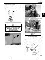
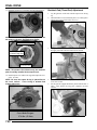
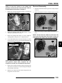
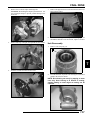
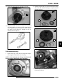
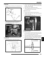
To change gearcase lubricant:
4.
Remove fill plug (8 mm hex) and check the O-ring.
Fill Plug
A
B
10 ft. lbs (14 Nm)
1.
2.
3.
Remove gearcase drain plug (B) (11 mm) located on the
bottom of the gearcase and drain oil. (The drain plug is
accessible through the skid plate.) Catch and discard used
oil properly.
Clean and reinstall drain plug (B) using a new sealing
washer (A). Toque to 10 ft. lbs. (14 Nm).
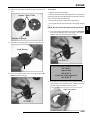
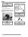
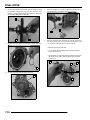
The fill plug can be accessed through the top hood area by
removing the storage box or by removing the left side panel
in the left wheel well.
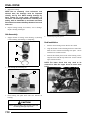
5.
Fill with the recommended fluid amount (5 oz.) or to the
bottom of the fill plug hole threads.
Front Gearcase
Plug Threads
Fill with 5 oz.
Top View of Hood Area
6.
Install fill plug and check for leaks.
Middle Gearcase Lubrication (6x6)
Middle Gearcase Specifications
LH Side Panel
Specified Lubricant:
ATV Angle Drive Fluid (PN 2871653)
Capacity: 6.75 oz. (200 ml.)
Drain Plug / Fill Plug Torque:
14 ft. lbs. (19.4 Nm)
The gearcase lubricant level should be checked and changed in
accordance with the maintenance schedule.
• Be sure vehicle is level with parking brake on before
proceeding.
• Check vent hose to be sure it is routed properly and
unobstructed.
• The correct middle gearcase lubricant to use is ATV
Angle Drive Fluid
2.22
GENERAL INFORMATION
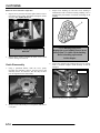
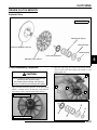
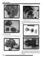
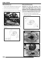
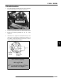
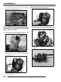
Rear Gearcase Lubrication (4x4)
To check the lubricant level:
The gearcase must be drained and re-filled with the proper
amount of lubricant. Refer to the procedure below.
REAR GEARCASE SPECIFICATIONS
To change middle gearcase lubricant:
1.
2.
3.
4.
5.
6.
7.
With the RANGER on a level surface, remove the fill plug
and check the lubricant level. Lubricant should be kept at
the specified level, according to the proper gearcase
specifications listed.
Support the vehicle securely with a jack stand and remove
the front tire on the driver’s side.
Remove gearcase drain plug located on the bottom of the
gearcase and drain oil. (The drain plug is accessible through
the skid plate.) Catch and discard used oil properly.
Clean and reinstall drain plug using a new sealing washer.
Remove fill plug.
Fill with the recommended fluid amount or fill to the
bottom of the threads of the fill plug hole.
Install fill plug. Check for leaks.
Specified Lubricant:
ATV Angle Drive Fluid (PN 2871653)
Capacity: 18 oz. (532 ml)
Fill Plug Torque: 40 ft. lbs. (54 Nm)
Drain Plug Torque: 30-45 in. lbs. (3-5 Nm)
To check the level:
1.
2.
MIDDLE GEARCASE (6X6)
Make sure vent is unobstructed
With machine on level ground and with the parking brake
on, remove fill plug from rear gearcase.
The fluid level should be 0.75 in. (1.9 cm) from the bottom
of the fill plug hole threads. Use a light colored and nonabsorbent measuring instrument (white zip tie) to measure
the depth of the fluid in the rear gearcase. If level is low,
add ATV Angle Drive Fluid (PN 2871653).
Side View
0.75 in.
(1.9 cm)
Measuring
Instrument
0.75 in.
(1.9 cm)
Fill to bottom of
fill plug hole
threads: 6.75 oz.
Fluid Level
Fill Plug
14 ft. lbs. (19 Nm)
Bottom View
3.
4.
Reinstall fill plug. Tighten to 40 ft. lbs. (54 Nm).
Check for leaks.
Drain Plug
14 ft. lbs. (19 Nm)
2.23
2
GENERAL INFORMATION
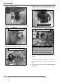
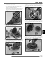
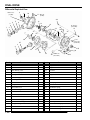
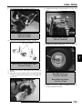
Rear Gearcase Lubrication (6x6)
To change the lubricant:
1.
Remove gearcase drain plug located on the bottom and
drain the oil. Catch and discard used oil properly.
Rear Gearcase Specifications
Under Side View
Specified Lubricant:
ATV Angle Drive Fluid (PN 2871653)
Capacity: 10 Oz. (300 ml.)
Drain Plug / Fill Plug Torque:
14 ft. lbs. (19.4 Nm)
Drain Plug
30-45 in. lbs.
(3-5 Nm)
2.
3.
The gearcase lubricant level should be checked and changed in
accordance with the maintenance schedule.
• Be sure vehicle is level before proceeding with parking
brake on.
Clean and reinstall the drain plug with a new sealing washer
and tighten to 30-45 in. lbs. (3-5 Nm).
Remove fill plug.
• Check vent hose to be sure it is routed properly and
unobstructed.
• The correct rear gearcase lubricant to use is Polaris
ATV Angle Drive Fluid
To check the lubricant level:
The gearcase must be drained and re-filled with the proper
amount of lubricant. Refer to the procedure below.
To change rear gearcase lubricant:
Fill Plug
40 ft. lbs.
(54 Nm)
4.
5.
1.
Add 18 oz. (532 ml.) of ATV Angle Drive Fluid
(PN 2871653).
Reinstall fill plug. Tighten to 40 ft. lbs (54 Nm).
2.
3.
4.
With the vehicle on a level surface, remove the fill plug
and check the lubricant level. Lubricant should be kept at
the specified level, according to the proper gearcase
specifications listed.
Support the vehicle securely with a jack stand and remove
the front tire on the driver’s side.
Remove gearcase drain plug located on the bottom of the
gearcase and drain oil. (The drain plug is accessible through
the skid plate.) Catch and discard used oil properly.
Clean and reinstall drain plug using a new sealing washer.
REAR GEARCASE - 6X6
Make sure vent is unobstructed
40 ft. lbs
(54 Nm)
Fill Plug
6.
Check for leaks.
Drain Plug
2.24
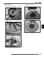
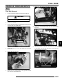
GENERAL INFORMATION
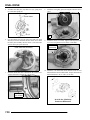
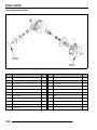
5.
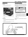
Coolant Level Inspection
Remove fill plug (A).
The recovery bottle, located on the left side of the machine, must
be maintained between the minimum and maximum levels
indicated on the recovery bottle.
A
6.
7.
Surge Tank Cap
2
Fill with 10 oz. (300 ml.) or fill to the bottom of the threads
of the fill plug hole.
Install fill plug and torque to 14 ft. lbs (19 Nm). Check for
leaks.
COOLING SYSTEM
With the engine at operating temperature, the coolant level
should be between the upper and lower marks on the coolant
reservoir. If not:
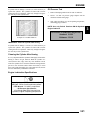
Liquid Cooling System Overview
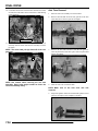
1.
The engine coolant level is controlled or maintained by the
recovery system. The recovery system components are the
recovery bottle, radiator filler neck, radiator pressure cap and
connecting hose.
2.
As coolant operating temperature increases, the expanding
(heated) excess coolant is forced out of the radiator past the
pressure cap and into the recovery bottle. As engine coolant
temperature decreases the contracting (cooled) coolant is drawn
back up from the tank past the pressure cap and into the radiator.
3.
Remove reservoir cap. Inner splash cap vent hole must be
clear and open.
Fill reservoir to upper mark with Polaris Premium 60/40
Anti Freeze / Coolant or 50/50 or 60/40 mixture of
antifreeze and distilled water as required for freeze
protection in your area.
Reinstall cap.
NOTE: Some coolant level drop on new machines is
normal as the system is purging itself of trapped air.
Observe coolant levels often during the break-in
period.
Overheating of engine could occur if air is not fully purged from
system.
Polaris Premium 60/40 is already premixed and ready to use. Do
not dilute with water.
Surge Tank
NOTE: If overheating is evident, allow system to
cool completely and check coolant level in the
radiator and inspect for signs of trapped air in
system.
2.25
GENERAL INFORMATION
Radiator Coolant Level Inspection
• Straight water or antifreeze may cause the system to
freeze, corrode, or overheat.
NOTE: This procedure is only required if the cooling
system has been drained for maintenance and/or
repair. However, if the recovery bottle has run dry,
or if overheating is evident, the level in the radiator
should be inspected and coolant added if necessary.
Radiator Cap
Polaris 60/40 Anti-Freeze / Coolant
(PN 2871323)
Cooling System Pressure Test
Refer to Chapter 3 for cooling system pressure test procedure.
Cooling System Hoses
1.
Inspect all hoses for cracks, deterioration, abrasion or
leaks. Replace if necessary.
Coolant Lines
WARNING
Never remove the pressure cap when the
engine is warm or hot. Escaping steam can
cause severe burns. The engine must be cool
before removing the pressure cap.
NOTE: Use of a non-standard pressure cap will not
allow the recovery system to function properly.
To access the radiator pressure cap raise the front hood.
The radiator cap is located on the drivers side.
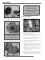
Coolant Strength / Type
Test the strength of the coolant using an antifreeze hydrometer.
Antifreeze Hydrometer
• A 50/50 or 60/40 mixture of antifreeze and distilled
water will provide the optimum cooling, corrosion
protection, and antifreeze protection.
• Do not use tap water, straight antifreeze, or straight
water in the system. Tap water contains minerals and
impurities which build up in the system.
2.26
Radiator
2.
Check tightness of all hose clamps.
CAUTION
Do not over-tighten hose clamps at radiator, or
radiator fitting may distort, causing a restriction
to coolant flow. Radiator hose clamp torque is
36 in. lbs. (4 Nm).
GENERAL INFORMATION
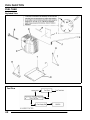
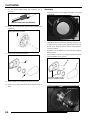
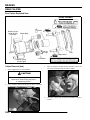
Radiator
1.
4.
Check radiator (A) air passages for restrictions or damage.
A
5.
Remove the outlet radiator hose, inlet radiator hose, surge
tank hose, and overflow hose from the radiator.
Remove the radiator.
Inlet Radiator Hose
2
Outlet Radiator Hose
2.
3.
Carefully straighten any bent radiator fins.
Remove any obstructions with compressed air or low
pressure water.
Surge Tank Hose
Plug
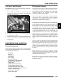
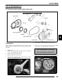
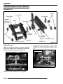
Coolant Drain / Radiator Removal
1.
Remove the front bumper. Remove three bolts that secure
the bumper to the bottom of the frame. Remove six screws
(both sides) that secure the wheel well panel to the frame.
Remove two bolts that secure the top bumper to the frame.
Remove the darts that attach the plastic to the bumper.
Bolts
Wheel Well
FINAL DRIVE / WHEEL AND TIRE
Wheel, Hub, and Spindle Torque Table
Item
Nut Type
Specification
Aluminum Wheels
(Cast)
Lug Nut (1)
Steel Wheels
(Black / Camo)
Flange Nut (2) 35 ft. lbs. (47 Nm)
90 ft. lbs. (122 Nm)
Front Spindle Nut
-
70 Ft. Lbs. (95 Nm)
Rear & Center Hub
Retaining Nut
-
110 Ft. Lbs. (150 Nm)
Bolts
2.
Remove two mounting screws that secure the top of the
radiator to the frame. Remove the radiator cap. Pull the
radiator out of the frame at an angle.
NOTE: If you have trouble reaching the top radiator
bolts, remove four screws from the top front of the
hood liner. Prop the front of the hood up 1.5 inches
(38.10 mm) to help remove the top bolts that secure
the radiator to the frame.
3.
#2
#1
Aluminum Wheel
Steel Wheel
(LE Models)
90 ft. lbs. (122 Nm)
(Standard Models)
35 ft. lbs. (47 Nm)
Remove the drain plug and drain the coolant from the
radiator. Drain the coolant into a suitable container and
properly dispose of the coolant.
2.27
GENERAL INFORMATION
CV Shaft Boot Inspection
Inspect the CV shaft boots in the front and rear of the RANGER
for damage, tears, wear, or leaking grease. If the rubber boot
exhibits any of these symptoms, replace the boot. Refer to
Chapter 7 for CV boot replacement, or have you Polaris dealer
replace the boot.
4.
Securely tighten the wheel nuts to the proper torque listed
in the torque table at the beginning of this section.
CAUTION
If wheels are improperly installed it could affect
vehicle handling and tire wear. On vehicles with
tapered rear wheel nuts, make sure tapered end
of nut goes into taper on wheel.
Tire Inspection
• Improper tire inflation may affect vehicle
maneuverability.
• When replacing a tire always use original equipment
size and type.
Inspect Boots
Wheel Removal
Front & Rear
Wheel Nuts (4)
• The use of non-standard size or type tires may affect
vehicle handling.
Tire Tread Depth
Always replace tires when tread depth is worn to 1/8" (3 mm) or
less.
Tread
Depth 1/8" (3 mm)
Front Hub Nut
70 ft. lbs. (95 Nm)
Rear Hub Nut
110 ft. lbs. (150 Nm)
1.
2.
3.
4.
Stop the engine, place the transmission in gear and lock the
parking brake.
Loosen the wheel nuts slightly.
Elevate the side of the vehicle by placing a suitable stand
under the footrest frame.
Remove the wheel nuts and washers and remove the wheel.
Wheel Installation
1.
2.
3.
With the transmission in gear and the parking brake
locked, place the wheel in the correct position on the wheel
hub. Be sure the valve stem is toward the outside and
rotation arrows on the tire point toward forward rotation.
Attach the washers (if applicable) and wheel nuts and finger
tighten them.
Lower the vehicle to the ground.
2.28
WARNING
Operating a RANGER with worn tires will
increase the possibility of the vehicle skidding
easily with possible loss of control.
Worn tires can cause an accident.
Always replace tires when the tread depth
measures 1/8", (.3 cm) or less.
GENERAL INFORMATION
Tire Pressure
CAUTION
Maintain proper tire pressure.
Refer to the warning tire pressure decal
applied to the vehicle.
NOTE: Batteries must be fully charged before use or
battery life will be reduced by 10-30% of full
potential. Charge battery for 3-5 hours at a current
equivalent of 1/10 of the battery’s rated amp/hour
capacity. Do not use the alternator to charge a new
battery.
(Refer
to
Battery
Activation
and
Maintenance video PN 9917987)
Battery Fluid Level (Conventional Battery)
Tire Pressure Inspection (PSI - Cold)
Front
Rear
8-12
8-12
A poorly maintained battery will deteriorate rapidly. Check the
battery fluid level often. Maintain the fluid level between the
upper and lower level marks.
Upper Level
ELECTRICAL AND IGNITION SYSTEM
Battery Maintenance
Keep battery terminals and connections free of corrosion. If
cleaning is necessary, remove the corrosion with a stiff wire
brush. Wash with a solution of one tablespoon baking soda and
one cup water. Rinse well with tap water and dry off with clean
shop towels. Coat the terminals with dielectric grease or
petroleum jelly.
Be careful not to allow cleaning solution or tap water into the
battery
WARNING
Battery electrolyte is poisonous. It contains
sulfuric acid. Serious burns can result from
contact with skin, eyes or clothing. Antidote:
Lower Level
Add only distilled water. Tap water contains minerals that are
harmful to a battery.
Battery Removal
1.
Open the Hood.
2.
3.
4.
Remove the battery vent tube from the battery.
Disconnect the black (negative) battery cable.
Disconnect the red (positive) battery cable.
External: Flush with water.
Internal: Drink large quantities of water or milk.
Follow with milk of magnesia, beaten egg, or
vegetable oil. Call physician immediately.
Eyes: Flush with water for 15 minutes and get
prompt medical attention.
Batteries produce explosive gases.
Keep sparks, flame, cigarettes, etc. away.
Ventilate when charging or using in an enclosed
space. Always shield eyes when
working near batteries.
KEEP OUT OF REACH OF CHILDREN.
2.29
2
GENERAL INFORMATION
5.
Lift the battery out of the vehicle, being careful not to tip
it sideways and spill any electrolyte.
Spark Plug Service
1.
CAUTION
Remove both spark plug high tension leads (A). Clean
plug area so no dirt and debris can fall into engine when
plug is removed.
To reduce the chance of sparks: Whenever
removing the battery, disconnect the negative
(black) cable first. When reinstalling the battery,
install the negative cable last.
A
Battery Installation
Using a new battery that has not been fully charged can damage
the battery and result in a shorter life. It can also hinder vehicle
performance. Follow the battery charging procedure before
installing the battery.
1. Ensure that the battery is fully charged.
2. Place the battery in the battery holder.
3. Install the battery vent tube.
NOTE: The vent tube must be free of obstructions
and securely installed. Route the tube away from the
frame and vehicle body to prevent contact with
electrolyte.
4.
5.
6.
7.
B
2.
Remove spark plugs (B).
3.
Inspect electrodes for wear and carbon buildup. Look for
a sharp outer edge with no rounding or erosion of the
electrodes.
Inspect electrode for
wear and buildup
Coat the terminals with dielectric grease or petroleum jelly.
Connect and tighten the red (positive) cable first.
Connect and tighten the black (negative) cable last.
Verify that cables are properly routed.
Battery Storage
Whenever the vehicle is not used for a period of three months or
more, remove the battery from the vehicle, ensure that it's fully
charged, and store it out of the sun in a cool, dry place. Check
battery voltage each month during storage and recharge as
needed to maintain a full charge.
NOTE: Battery charge can be maintained by using a
Polaris battery tender charger or by charging about
once a month to make up for normal self-discharge.
Battery tenders can be left connected during the
storage period, and will automatically charge the
battery if the voltage drops below a pre-determined
point.
4.
Clean with electrical contact cleaner or a glass bead spark
plug cleaner only. CAUTION: A wire brush or coated
abrasive should not be used.
5.
Measure gap with a wire gauge. Refer to specifications in
picture below for proper spark plug type and gap. Adjust
gap if necessary by bending the side electrode carefully.
Spark Plug Gap
Battery Charging
1.
2.
3.
Remove the battery from the vehicle to prevent damage
from leaking or spilled electrolyte during charging.
Charge the battery with a charging output no larger than
1/10 of the battery’s amp/hr rating. Charge as needed to
raise the specific gravity to 1.270 or greater.
Reinstall the battery.
2.30
Gap - .035" (0.90 mm)
6.
If necessary, replace spark plug with proper type.
CAUTION: Severe engine damage may occur if the
incorrect spark plug is used.
7.
Apply a small amount of anti-seize compound to the spark
plug threads.
GENERAL INFORMATION
8.
Install spark plug and torque to specification
Recommended Spark Plug:
Champion RC7YC3
Spark Plug Torque:
18 Ft. Lbs. (24 Nm)
WARNING
Due to the critical nature of the procedures
outlined in this chapter, Polaris recommends
steering component repair and adjustment be
performed by an authorized Polaris MSDcertified technician when replacing worn or
damaged steering parts.
Use only genuine Polaris replacement parts.
Engine To Frame Ground
Inspect engine ground cable connection. Be sure it is clean and
tight. The ground cable runs from the engine to the terminal
block located under the front hood next to the battery.
One of two methods can be used to measure toe alignment. The
string method and the chalk method. If adjustment is required,
refer to following pages for procedure.
Tie Rod End / Steering Inspection
Black Ground
• To check for play in the tie rod end, grasp the steering
tie rod, pull in all directions feeling for movement.
• Repeat inspection for inner tie rod end (on steering
post).
Terminal Block
(under hood)
• Replace any worn steering components. Steering
should move freely through entire range of travel
without binding.
STEERING AND SUSPENSION
Steering
The steering components should be checked periodically for
loose fasteners, worn tie rod ends, and damage. Also check to
make sure all cotter pins are in place. If cotter pins are removed,
they must not be re-used. Always use new cotter pins.
Replace any worn or damaged steering components. Steering
should move freely through entire range of travel without
binding. Check routing of all cables, hoses, and wiring to be
sure the steering mechanism is not restricted or limited.
NOTE: Whenever
steering
components
are
replaced, check front end alignment. Use only
genuine Polaris parts.
• Elevate front end of machine so front wheels are off the
ground. Check for any looseness in front hub / wheel
assembly by grasping the tire firmly at top and bottom
first, and then at front and rear. Try to move the wheel
and hub by pushing inward and pulling outward.
• If abnormal movement is detected, inspect the hub and
wheel assembly to determine the cause (loose wheel
nuts or loose front hub nut).
• Refer to the Body/Steering or Final Drive chapter for
more information.
Camber and Caster
The camber and caster are non-adjustable.
2.31
2
GENERAL INFORMATION
Wheel Toe Alignment Inspection
Toe Adjustment
1.
2.
If toe alignment is incorrect, measure the distance between
vehicle center and each wheel. This will tell you which tie rod
needs adjusting.
3.
Place machine on a smooth level surface.
Set steering wheel in a straight ahead position and secure
the steering wheel in this position.
Place a chalk mark on the center line of the front tires
approximately 10” (25.4 cm) from the floor or as close to
the hub/axle center line as possible.
NOTE: Be sure steering wheel is straight ahead
before determining which tie rod(s) need
adjustment.
CAUTION
During tie rod adjustment, it is very important that
the following precautions be taken when
tightening tie rod end jam nuts.
If the rod end is positioned incorrectly it will not
pivot, and may break.
To adjust toe alignment:
• Hold tie rod end to keep it from rotating.
• Loosen jam nuts at both end of the tie rod.
Chalk Mark
Measurement “A”
Measurement “B”
NOTE: It is important that the height of both marks
be equally positioned in order to get an accurate
measurement.
4.
5.
6.
Measure the distance between the marks and record the
measurement. Call this measurement “A”.
Rotate the tires 180° by moving vehicle forward or
backward. Position chalk marks facing rearward, even with
the hub/axle centerline.
Again measure the distance between the marks and record.
Call this measurement “B”. Subtract measurement “B”
from measurement “A”. The difference between
measurements “A” and “B” is the vehicle toe alignment.
The recommended vehicle toe tolerance is 1/8”, to 1/4”, (.3
to .6 cm) toe out. This means the measurement at the front
of the tire (A) is 1/8”, to 1/4”, (.3 to .6 cm) wider than the
measurement at the rear (B).
= In. / mm.
Wheel Toe-Out:
(A) - (B) = 1/8 - 1/4" (.3 to .6 cm)
• Shorten or lengthen the tie rod until alignment is as
required to achieve the proper toe setting as specified in
“Wheel Toe Alignment”.
• IMPORTANT: When tightening the tie rod end jam
nuts, the rod ends must be held parallel to prevent rod
end damage and premature wear. Damage may not be
immediately apparent if done incorrectly.
Hold
Rod End
Correctly
Tightened
Jam Nut
Incorrectly
Tightened
Jam Nut
• After alignment is complete, torque jam nuts to 12-14
ft. lbs. (16-19 Nm).
=T
Tie Rod Jam Nut Torque:
12-14 ft. lbs. (16-19 Nm)
2.32
GENERAL INFORMATION
Front Suspension
Rear Suspension
• Compress and release front suspension. Damping
should be smooth throughout the range of travel.
• Check all front suspension components and fasteners
for wear or damage.
2
• Inspect front strut cartridges for leakage.
Bolt Torque
15 ft. lbs. (20 Nm)
RANGER 4X4
Independent Rear Suspension
Inspect for leaks
RANGER 6X6
Rear Swingarm Suspension
• Compress and release rear suspension. Damping should
be smooth throughout the range of travel.
• Check all rear suspension components for wear or
damage.
• Inspect shock for leakage.
2.33
GENERAL INFORMATION
Rear Suspension Adjustment (4x4)
BRAKE SYSTEM
The rear suspension may be adjusted to provide a stiffer
suspension if necessary.
Brake System Inspection
1.
2.
3.
Remove the top shock mounting bolts from the inside
mounting holes.
Reposition the shocks to the outside mounting holes.
Reinstall the shock mounting bolts. Torque to 30 ft. lbs. (40
Nm).
The following checks are recommended to keep the brake
system in good operating condition. Service life of brake system
components depends on operating conditions. Inspect brakes in
accordance with the maintenance schedule and before each ride.
Outside Mounting Holes
• Keep fluid level in the master cylinder reservoir to the
indicated level inside reservoir.
Inside Mounting Holes
• Use Polaris DOT 3 or DOT 4 Brake Fluid.
• Check brake system for fluid leaks.
Rear Spring Adjustment
The rear shock absorber springs are adjusted by rotating the
adjustment cam either clockwise or counterclockwise to
increase or decrease spring tension.
To adjust the suspension, use the adjustment cam located near
the bottom of the rear shock. This will allow you to increase or
decrease the amount of spring preload.
• Check brake for excessive travel or spongy feel.
• Check friction pads for wear, damage or looseness.
• Check surface condition of the disc.
Brake Pad Inspection
Pads should be changed when the friction material is worn to
.180" (4.6 mm). When the pad are new the thickness is .298 ±
.007" (7.56 ± .178 mm).
Rear Spring
Adjustment Cam
Brake Pad
Measure
Thickness
Service Limit - .180" (4.6 mm)
Shock Spanner Wrench
(PN 2870872)
2.34
GENERAL INFORMATION
Parking Brake Pad Inspection
Measure the thickness of the rear caliper parking brake pads.
Replace assembly as needed. See illustration below for proper
readings.
Inboard Pad Thickness
New .304” (7.72 mm)
Limit: 0.24” (6.1 mm)
Inboard
Pad
2
Outboard
Pad
Outboard Pad Thickness
New 0.360” (9.14 mm)
Limit: 0.31” (7.87 mm)
Installed Disc to Park Brake
0.375” (0.953 cm)
New Rotor Disc Thickness
0.150” - 0.164”
(3.81 - 4.16 mm)
Brake Hose and Fitting Inspection
Check brake system hoses and fittings for cracks, deterioration,
abrasion, and leaks. Tighten any loose fittings and replace any
worn or damaged parts.
2.35
ENGINE
CHAPTER 3
ENGINE
ENGINE SPECIFICATIONS . . . . . . . . . . . . . . . . . . . . . . . . . . . . . . . . . . . . . . . . . . . . . . . 3.2
CRANKCASE EXPLODED VIEWS . . . . . . . . . . . . . . . . . . . . . . . . . . . . . . . . . . . . . . . . . 3.2
ENGINE FASTENER TORQUE PATTERNS . . . . . . . . . . . . . . . . . . . . . . . . . . . . . . . . . . 3.9
TORQUE SPECIFICATIONS . . . . . . . . . . . . . . . . . . . . . . . . . . . . . . . . . . . . . . . . . . . . . 3.10
700 EFI ENGINE SERVICE SPECIFICATIONS. . . . . . . . . . . . . . . . . . . . . . . . . . . . . . . 3.11
SPECIAL TOOLS . . . . . . . . . . . . . . . . . . . . . . . . . . . . . . . . . . . . . . . . . . . . . . . . . . . . . . 3.13
GENERAL ENGINE SERVICE . . . . . . . . . . . . . . . . . . . . . . . . . . . . . . . . . . . . . . . . . . . . 3.13
ACCESSIBLE COMPONENTS. . . . . . . . . . . . . . . . . . . . . . . . . . . . . . . . . . . . . . . . . . . . 3.13
PISTON IDENTIFICATION . . . . . . . . . . . . . . . . . . . . . . . . . . . . . . . . . . . . . . . . . . . . . . . 3.13
COOLING SYSTEM SPECIFICATIONS. . . . . . . . . . . . . . . . . . . . . . . . . . . . . . . . . . . . . 3.13
COOLING SYSTEM PRESSURE TEST. . . . . . . . . . . . . . . . . . . . . . . . . . . . . . . . . . . . . 3.14
COOLING SYSTEM EXPLODED VIEW. . . . . . . . . . . . . . . . . . . . . . . . . . . . . . . . . . . . . 3.15
COOLING SYSTEM BLEEDING PROCEDURE . . . . . . . . . . . . . . . . . . . . . . . . . . . . . . 3.15
VALVE COVER REMOVAL - 6X6 MODELS (ENGINE INSTALLED) . . . . . . . . . . . . . . 3.17
ENGINE REMOVAL . . . . . . . . . . . . . . . . . . . . . . . . . . . . . . . . . . . . . . . . . . . . . . . . . . . . 3.18
ENGINE INSTALLATION NOTES . . . . . . . . . . . . . . . . . . . . . . . . . . . . . . . . . . . . . . . . . 3.19
CYLINDER HONE SELECTION AND HONING PROCEDURE . . . . . . . . . . . . . . . . . . . 3.20
HONING TO DEGLAZE . . . . . . . . . . . . . . . . . . . . . . . . . . . . . . . . . . . . . . . . . . . . . . . . . 3.20
CLEANING THE CYLINDER AFTER HONING . . . . . . . . . . . . . . . . . . . . . . . . . . . . . . . 3.21
ENGINE LUBRICATION SPECIFICATIONS . . . . . . . . . . . . . . . . . . . . . . . . . . . . . . . . . 3.21
OIL PRESSURE TEST . . . . . . . . . . . . . . . . . . . . . . . . . . . . . . . . . . . . . . . . . . . . . . . . . . 3.21
OIL FLOW CHART . . . . . . . . . . . . . . . . . . . . . . . . . . . . . . . . . . . . . . . . . . . . . . . . . . . . . 3.22
3
ENGINE DISASSEMBLY AND INSPECTION . . . . . . . . . . . . . . . . . . . . . . . . . . . . . . . . . 3.23
CYLINDER HEAD ASSEMBLY EXPLODED VIEW . . . . . . . . . . . . . . . . . . . . . . . . . . . . 3.23
ROCKER ARMS / PUSH RODS. . . . . . . . . . . . . . . . . . . . . . . . . . . . . . . . . . . . . . . . . . . 3.24
CYLINDER HEAD REMOVAL . . . . . . . . . . . . . . . . . . . . . . . . . . . . . . . . . . . . . . . . . . . . 3.24
CYLINDER HEAD INSPECTION . . . . . . . . . . . . . . . . . . . . . . . . . . . . . . . . . . . . . . . . . . 3.25
CYLINDER HEAD WARP . . . . . . . . . . . . . . . . . . . . . . . . . . . . . . . . . . . . . . . . . . . . . . . . 3.25
VALVE SEAL / SPRING SERVICE (ON ENGINE) . . . . . . . . . . . . . . . . . . . . . . . . . . . . . 3.25
CYLINDER HEAD DISASSEMBLY . . . . . . . . . . . . . . . . . . . . . . . . . . . . . . . . . . . . . . . . 3.26
VALVE INSPECTION . . . . . . . . . . . . . . . . . . . . . . . . . . . . . . . . . . . . . . . . . . . . . . . . . . . 3.27
COMBUSTION CHAMBER. . . . . . . . . . . . . . . . . . . . . . . . . . . . . . . . . . . . . . . . . . . . . . . 3.28
VALVE SEAT RECONDITIONING . . . . . . . . . . . . . . . . . . . . . . . . . . . . . . . . . . . . . . . . . 3.28
CYLINDER HEAD REASSEMBLY . . . . . . . . . . . . . . . . . . . . . . . . . . . . . . . . . . . . . . . . . 3.30
VALVE SEALING TEST . . . . . . . . . . . . . . . . . . . . . . . . . . . . . . . . . . . . . . . . . . . . . . . . . 3.31
CYLINDER REMOVAL . . . . . . . . . . . . . . . . . . . . . . . . . . . . . . . . . . . . . . . . . . . . . . . . . . 3.31
VALVE LIFTER REMOVAL / INSPECTION . . . . . . . . . . . . . . . . . . . . . . . . . . . . . . . . . . 3.31
PISTON REMOVAL . . . . . . . . . . . . . . . . . . . . . . . . . . . . . . . . . . . . . . . . . . . . . . . . . . . . 3.32
CYLINDER INSPECTION. . . . . . . . . . . . . . . . . . . . . . . . . . . . . . . . . . . . . . . . . . . . . . . . 3.33
PISTON-TO-CYLINDER CLEARANCE . . . . . . . . . . . . . . . . . . . . . . . . . . . . . . . . . . . . . 3.34
PISTON / ROD INSPECTION. . . . . . . . . . . . . . . . . . . . . . . . . . . . . . . . . . . . . . . . . . . . . 3.34
PISTON RING INSTALLED GAP . . . . . . . . . . . . . . . . . . . . . . . . . . . . . . . . . . . . . . . . . . 3.35
STARTER DRIVE BENDIX REMOVAL / INSPECTION . . . . . . . . . . . . . . . . . . . . . . . . . 3.35
FLYWHEEL / STATOR REMOVAL / INSPECTION . . . . . . . . . . . . . . . . . . . . . . . . . . . . 3.36
ENGINE CRANKCASE DISASSEMBLY / INSPECTION . . . . . . . . . . . . . . . . . . . . . . . . 3.36
CAMSHAFT INSPECTION . . . . . . . . . . . . . . . . . . . . . . . . . . . . . . . . . . . . . . . . . . . . . . . 3.44
ENGINE REASSEMBLY . . . . . . . . . . . . . . . . . . . . . . . . . . . . . . . . . . . . . . . . . . . . . . . . . 3.45
CRANKCASE REASSEMBLY . . . . . . . . . . . . . . . . . . . . . . . . . . . . . . . . . . . . . . . . . . . . 3.45
FLYWHEEL / STATOR INSTALLATION . . . . . . . . . . . . . . . . . . . . . . . . . . . . . . . . . . . . 3.54
CYLINDER HEAD REASSEMBLY . . . . . . . . . . . . . . . . . . . . . . . . . . . . . . . . . . . . . . . . . 3.54
OIL PUMP PRIMING . . . . . . . . . . . . . . . . . . . . . . . . . . . . . . . . . . . . . . . . . . . . . . . . . . . 3.57
TROUBLESHOOTING. . . . . . . . . . . . . . . . . . . . . . . . . . . . . . . . . . . . . . . . . . . . . . . . . . . 3.58
ENGINE . . . . . . . . . . . . . . . . . . . . . . . . . . . . . . . . . . . . . . . . . . . . . . . . . . . . . . . . . . . . . 3.58
COOLING SYSTEM . . . . . . . . . . . . . . . . . . . . . . . . . . . . . . . . . . . . . . . . . . . . . . . . . . . . 3.59
3.1
ENGINE
ENGINE SPECIFICATIONS
Crankcase Exploded Views
A.
B.
C.
D.
E.
F.
G.
H.
I.
J.
K.
L.
M.
N.
O.
Journal Bearings
Camshaft
Thrust Plate
Balance Shaft
Woodruff Key
Flange Seal
Crankshaft
Oil Pickup
Journal Bearings
Baffle
Oil Plug
Washer
O-ring
Crankcase
Crankcase Bolts
B
C
A
115 ± 12 in. lbs.
(13 ± 1.35 Nm)
D
F
E
60 ± 6 in. lbs.
(6.8 ± .68 Nm)
G
I
H
I
60 ± 6 in. lbs.
(6.8 ± .68 Nm)
J
NOTE: If needed, heat
the oil baffle bolts with a
heat gun to remove.
M
192 ± 24 in. lbs
K (21.7 ± 2.7 Nm)
L
N
Apply Loctite™ 242 to
bolt threads.
O
Apply White Lithium
Grease
22 ± 2 ft. lbs. (30 ± 3 Nm)
3.2
Apply Moly
Lube Grease.
ENGINE
Oil Pump / Water Pump / Engine Cover Exploded View
A
B
C
D
J
E
F
K
22 ± 2 ft. lbs. (30 ± 3 Nm)
A. Split Gear
B. Washer
C. Bolt
D. Oil Rotor
E. Oil Pump
F. Mag Gasket Cover
G. Impeller
H. Washer
I. Nut
J. Counterbalance Gear
K. Washer
L. Bolt
M. Oil Pump Bolts
N. Engine Cover
O. Wire Hold down
P. Stator Housing Bolts
L
G
M
H
I
84 ± 8 in. lbs. (9.5 ± .90 Nm)
No Grease on this
Portion of the Gasket!
N
Apply corrosion resistant
grease to stator grommet area.
108 ± 12 in.lbs.
(6.8 ± .68 Nm)
O
P
96 ± 3 in.lbs.
(10.85 ± 0.35 Nm)
Oil Pump Bolt Tighten Sequence
Mag Cover Bolt Tighten Sequence
Apply Polaris OW-40
oil to component
Apply White Lithium
Grease
3.3
3
ENGINE
Stator Cover / Starter / Water Pump Exploded View
Apply Polaris
Starter Grease
Apply Polaris 0W-40
oil to seal
Water Pump Cover
Bolt Tighten Sequence
5
3
2
7
1
4
Loctite™ Pipe Sealant
6
(PN 2871956)
J
No Grease or Oil
A
84 ± 8 ft.lbs. (9.5 ± 0.9 Nm)
K
L
B
Tighten Top Bolt First
96 ± 12 in. lbs.
(10.85 ± 1.35 Nm)
1st
2nd
C
D
E
O
108 ± 12 ft.lbs.
(12 ± 1.35 Nm)
F
N
M
65 ± 7 ft. lbs.
(88 ± 9.5 Nm)
G
I
A. Bolts
B. Starter
C. Washer
D. Nut
E. Positive Cable
F. Negative Cable
G. Gasket
H. Clamp
I. Bolts
J. Gasket
K. Water Pump Cover
L. Bolts
M. Crank Nut / Washer
N. Flywheel
3.4
H
96 ± 12 in. lbs. (10.85 ± 1.35 Nm)
Stator Cover Bolt
Tighten Sequence
ENGINE
Oil Filter / Pressure Relief / Dipstick Assembly Exploded View
A. Clamp
B. Oil Fill Tube
C. Dipstick
D. O-ring
E. Hex Plug
F. Oil Filter Nipple
G. Oil Filter
H. Dowel
I. Galley Plug Asm.
J. Screw
K. Relief Spring
C
3
B
50 ± 5 in. lbs.
22 ± 2 ft. lbs.
(30 ± 3 Nm)
J (5.65 ± 0.56 Nm)
I
K
A
H
D
18 ± 2 ft. lbs.
E (24.4 ± 2.71 Nm)
35 ± 4 ft. lbs.
F (47.5
± 5.4 Nm)
50 ± 5 in. lbs.
(5.65 ± 0.56 Nm)
G
3.5
ENGINE
Cylinder / Cylinder Head / Piston Exploded View
Lubricate threads & between
washers and underside of bolt heads
with engine oil.
Torque in sequence provided.
Initial:
35 ± 4 ft. lbs (47.5 ± 5.5 Nm)
in sequence. Finalize sequence
by tightening an additional 90°
(1/4 turn)
1
(Apply each
Bolt Threads)
Apply Moly Lube grease to
valve tips.
A
22 ± 2 ft. lbs.
Gasket free of oil. Verify tabs are (30 ± 3 Nm)
visible.
B
2C
Apply thin film of 0W- 40 to
25-55 mm of cylinder bore.
Head Bolt Tighten
Sequence
Apply 0W-40 to piston pin or pin
bore.
D3
Apply 0W- 40 to lifters.
F
Do Not install expansion plug
more than 1.5 mm inward.
1.5 mm
E
G
4
4
Side View
A.
B.
C.
D.
E.
F.
G.
H.
I.
J.
K.
L.
Head Bolts
Rocker Arms
Head Assembly
Gasket
Pushrods
Bushing
Expansion Plug
Cylinder
Piston Assembly
Circlip
Gasket
Hydraulic Lifter
Apply Polaris 0W-40 Oil
Apply Moly Lube Grease
3.6
H
I
5
3
UP
J Circlip
for Install
K
L
6
ENGINE
Engine Sensors / Valve Cover / General Component Exploded View
84 ± 8 in. lbs.
(9.5 ± 0.9 Nm)
A.
B.
C.
D.
E.
F.
G.
H.
I.
J.
K.
L.
M.
N.
O.
P.
Q.
R.
S.
A
B
C
Screws
20 ± 5 in. lbs.
Rocker Cover
(2.5 ± 0.55 Nm) E
Breather
O-ring Seal
18 ± 2 ft. lbs. F
Breather Bolts
(24.5 ± 2.7 Nm)
Spark Plugs
(Apply Dielectric Grease
Intake Boot
to threads of Spark Plug)
Bolts
Boot Clamp
G
18 ± 2 ft. lbs.
Throttle Body
(24.5 ± 2.7 Nm)
Crank Position Sensor
H
Thermistor
O-ring
20 ± 5 in. lbs.
Thermostat
(2.5 ± 0.55 Nm) I
Bolts
Gasket
Exhaust Manifold
Bolts
J
Thermostat Housing
3
D
K
Apply Corrosion
Resistant Grease
84 ± 4 in. lbs.
(9.5 ± 0.9 Nm)
17 ± 2 ft. lbs.
L (23 ± 3 Nm)
P
S
Q
M
O
R
18 ± 2 ft. lbs.
(24.5 ± 2.7 Nm)
N
84 ± 8 in. lbs.
(9.5 ± 0.9 Nm)
3.7
ENGINE
EFI Harness / Fuel Injection Exploded View
A. Fuel Injector
B. Fuel Rail
C. EFI Harness
B
A
18 ± 2 ft. lbs.
(24.5 ± 2.7 Nm)
C
NOTE: See Chapter 4 for more information on the EFI system.
3.8
ENGINE
Engine Fastener Torque Patterns
Crankcase Bolt Tighten Sequence
3
22 ± 2 ft. lbs. (30 ± 3 Nm)
Cylinder Head Bolt Tighten Sequence
Lubricate threads and between washer and underside of bolt with engine oil.
Torque in sequence to spec provided, allow the gasket to set for 1 minute, then
tighten in sequence 90° (1/4 turn).
35 ± 4 ft. lbs.
(47.5 ± 5.5 Nm) + 90° (1/4 turn)
3.9
ENGINE
Torque Specifications
Engine Torque Specifications
Fastener
Size
in. lbs. (Nm)
ft. lbs. (Nm)
Camshaft Gear
8 mm
22 ± 2 (30 ± 3)
Camshaft Thrust Plate
6 mm
115 ± 12 (13 ± 1.35)
9.5 ± 1 (13 ± 1.35)
Throttle Body Adaptor Bolts
8 mm
216 ± 24 (24.5-± 2.7)
18 ± 2 (24.5 ± 2.7)
Counterbalance Gear
8 mm
22 ± 2 (30 ± 3)
Crankcase Bolts
8 mm
* 22 ± 2 (30 ± 3)
Crankcase Breather
5 mm
Cylinder Head Bolts
11 mm
Exhaust Manifold
8 mm
Flywheel
14 mm
Injector Rail
8 mm
216 ± 24 (24.5 ± 2.70)
18 ± 2 (24.5 ± 2.7)
Magneto Cover
6 mm
* 96 ± 3 (10.85 ± 0.35)
-
Oil Baffle Weldment
5 mm
60 ± 6 (6.8 ± 0.68)
-
Oil Drain Bolt (Crankcase)
12 mm
192 ± 24 (21.7 ± 2.7)
16 ± (21.7)
Oil Fill Tube Bolt
5 mm
50 ± 5 (5.64 ± 0.56)
-
Oil Filter Pipe Fitting
20 mm
Oil Pick Up
5 mm
60 ± 6 (6.8 ± 0.68)
-
Oil Pressure Relief Plug
10 mm
22 ± 2 (30 ± 3)
-
Oil Pump Housing Screw
6 mm
* 84 ± 8 (9.50 ± 0.90)
-
Rocker Arm
8 mm
Rocker Cover
6 mm
* 84 ± 8 (9.5 ± 0.9)
-
Spark Plug
14 mm
216 ± 24 (24.5 ± 2.7)
18 ± 2 (24.5 ± 2.7)
Starter Motor
6 mm
* 84 ± 8 (9.5 ± 0.9)
-
Stator Assembly
6 mm
96 ± 3 (10.85 ± 0.35)
-
Stator Housing
6 mm
* 96 ± 3 (10.85 ± 0.35)
-
20 ± 5 (2.5 ± 0.55)
* 35 ± 4 (47.5 ± 5.5)
216 ± 24 (24.5 ± 2.70)
18 ± 2 (24.5 ± 2.7)
65 ± 7 (88 ± 9.50)
35 ± 4 (47.5 ± 5.4)
* 22 ± 2 (30 ± 3)
Temperature Switch
3/8 NPT
17 ± 2 (23 ± 3)
Thermostat Housing
6 mm
Timing Plug
3/4-16
Trigger Coil/Stator Wire Holddown
5 mm
* 96 ± 3 (10.85 ± 0.35)
-
Water Pump Housing Cover
6 mm
* 96 ± 3 (10.85 ± 0.35)
-
Water Pump Impeller Nut
8 mm
108 ± 3 (12 ± 0.35)
-
84 ± 8 (9.5 ± 0.9)
7 - 9 (10 - 12)
NOTE: * See exploded views for notes or torque sequences.
3.10
-
ENGINE
700 EFI Engine Service Specifications
Cylinder Head - Engine Specifications
Main Component: Cylinder Head
Camshaft
Counter Balance
EH068OLE
Cam Lobe Height - Intake / Exhaust
1.3334" (33.8674 mm)
Camshaft Journal Outer Diameter - Mag
1.654" ± 0.00039" (42 ± 0.010 mm)
Camshaft Journal Outer Diameter - Center
1.634"± 0.00039" (41.50 ± 0.010 mm)
Camshaft Journal Outer Diameter - PTO
1.614" ± 0.00039" (41 ± 0.010 mm)
Camshaft Journal Bore Inner Diameter - Mag
1.656" ± 0.00039" (42.07 ± 0.010 mm)
Camshaft Journal Bore Inner Diameter - Center
1.637" ± 0.00039" (41.58 ± 0.010 mm)
Camshaft Journal Bore Inner Diameter - PTO
1.617" ± 0.00039" (41.07 ± 0.010 mm)
Camshaft Oil Clearance
0.00276" ± 0.00079" (0.07 ± 0.02 mm)
Camshaft End Play
0.0167" ± 0.0098" (0.425 ± 0.25 mm)
Counter Balance End Play
0.005" (0.127 mm)
Cylinder Head - Surface warp limit
0.00394" (0.1 mm)
Cylinder Head - Standard height
3.478" (88.35 mm)
Valve Seat - Contacting Width - Intake
0.0472" ± 0.00787" - 0.0039"
(1.20 ± 0.20 - 0.10mm)
Valve Seat - Contacting Width - Exhaust
0.0591" ± 0.00787" - 0.0039"
(1.50 ± 0.20 - 0.10 mm)
Valve Seat Angle
45.5° ± 0.255°
Valve Guide Inner diameter
0.2367" ± 0.00029" (6.012 ± 0.007 mm)
Valve Guide Protrusion Above Head
0.807" ± 0.0039" (20.50 ± 0.01 mm)
Valve Margin Thickness - Intake
Standard: 0.79" (20.06 mm)
Max- 0.98" (24.89 mm) Min.- 0.59" (14.98 mm)
Valve Margin Thickness - Exhaust
Standard: 0.80" (20.32 mm)
Max- 1.0" (25.4 mm) Min.- 0.60" (15.24 mm)
Valve Stem Diameter - Intake
0.2356" ± 0.00039" (5.985 ± 0.01 mm)
Valve Stem Diameter - Exhaust
0.2351" ± 0.00039" (5.972 ± 0.01 mm)
Valve Stem Oil Clearance - Intake
0.00228" ± 0.00098" (0.058 ± 0.025 mm)
Valve Stem Oil Clearance - Exhaust
0.00275" ± 0.00098" (0.0870 ± 0.025mm)
Valve Stem Overall Length - Intake
4.51" ± 0.01476" (114.5550 ± 0.375 mm)
Valve Stem Overall Length - Exhaust
4.5453" ± .01496" (115.45 ± 0.38 mm)
Valve Spring Overall Length - Free Length
1.735" (46.069 mm)
Valve Spring Overall Length - Installed Height
Intake - 1.4638" (37.18 mm)
Exhaust - 1.4736" (37.43 mm)
3
Cylinder Head
Valve Seat
Valve Guide
Valve
Valve Spring
3.11
ENGINE
Cylinder / Piston - Engine Specifications
Main Components: Cylinder / Piston / Connecting Rod
Cylinder
Lifter
Piston
Piston Pin
EH068OLE
Cylinder - Surface warp limit
(mating with cylinder head)
0.004" (0.10 mm)
Cylinder Bore - Standard
3.1495" (80 mm)
Cylinder Taper Limit
0.00031" (0.008 mm)
Cylinder Out of Round Limit
0.00030" (0.0075 mm)
Cylinder to Piston Clearance
.0015" ± .00059" (.040 ± .015mm)
Lifter Outer Diameter Standard
0.84245" ± 0.00025" (21.39 8 ± 0.00635 mm)
Lifter Block Bore
0.8438" ± 0.00062" (21.4322 ± 0.0157 mm)
Piston - Standard
3.1477" ± .000121" (79.954 ± .003mm)
Piston Standard Inner Diameter of
Piston Pin Bore
0.78789" ± .00009" (20.0125 ± 0.003 mm)
Piston Pin Outer Diameter
0.7874" - 0.7872" (20 - 19.995 mm)
Piston Pin - Standard Clearance - Piston Pin to
Pin Bore
0.00059" ± 0.0002" (0.015 ± 0.005 mm)
Piston Pin - Degree of Fit
Piston pin must be a push fit (by hand) at 68° F (20° C)
Piston / Connecting Rod / Crankshaft - Engine Specifications
Main Components: Piston / Connecting Rod
Installed
Gap
Piston Ring
Ring to
Groove
Clearance
Top Ring - Standard
0.0059± 0.138" (0.15 ± 0.35mm)
Top Ring - Limit
> 15% Leakdown
Second Ring - Standard
0.0098 ± 0.197" (0.25 ± 0.50mm)
Second Ring - Limit
> 15% Leakdown
Oil Ring - Standard
0.0196± 0.00984" (0.50 ± 0.25mm)
Oil Ring - Limit
> 15% Leakdown
Top Ring - Standard
0.0024" ± 0.0008" (0.060 ± 0.020 mm)
Top Ring - Limit
> 15% Leakdown
Second Ring - Standard
0.0028" ± 0.0008" (0.070 ± 0.020 mm)
Second Ring - Limit
> 15% Leakdown
Connecting Rod Small End I.D.
Connecting Rod
Crankshaft
3.12
EH068OLE
Connecting Rod Small End
Radial Clearance
Connecting Rod Big End
Side Clearance
Connecting Rod Big End
Radial Clearance
Crankshaft Runout Limit
0.789"− 0.78841" (20.030 − 20.015 mm)
0.0098"± 0.00039" (0.025 ± 0.010mm)
0.01181"± 0.00591" (0.030 ± 0.015mm)
0.0015"± 0.00006" (0.0038 ± 0.0015mm)
0.00236" (0.060mm)
ENGINE
Special Tools
Part Number
Tool Description
PV-43527
OIL FILTER WRENCH
2200634
VALVE SEAT RECONDITIONING KIT
PU-45257
VALVE SPRING COMPRESSOR
PU-45652
VALVE PRESSURE HOSE
2871043
FLYWHEEL PULLER
2870390
PISTON SUPPORT BLOCK
PU-45497-1
CAM GEAR SPRING INSTALLATION KIT
PU-45497-2
CAM GEAR TOOTH ALIGNMENT TOOL
PU-45498
CAM SPANNER WRENCH
PU-45838
GEAR HOLDER
3
PA-44995
WATER PUMP MECHANICAL SEAL INSTALLER
PU-45543
UNIVERSAL DRIVER HANDLE
PA-45483
MAIN SEAL INSTALLER
PU-45658
CRANKSHAFT MAIN SEAL SAVER
PA-45401
WATER PUMP SEAL SAVER
2870975
MITY VAC™ PRESSURE TEST TOOL
PU-45778
OIL SYSTEM PRIMING TOOL
GENERAL ENGINE SERVICE
Piston Identification
Accessible Components
Four stroke engine rings have a rectangular profile. See
“PISTON RING INSTALLED GAP” for ring installation. Use
the information below to identify pistons and rings.
Following Components can be serviced or removed with the
engine installed: (See Page 3.17 for 6x6 Valve Cover R & R)
• Flywheel
• Alternator (Stator)
• Starter Motor/Drive
Engine Model
Piston Diameter
EH068OLE
80 mm
Cooling System Specifications
• Cylinder Head (6x6: See Page 3.17)
• Cylinder (6x6: See Page 3.17)
Condition
• Piston / Rings (6x6: See Page 3.17)
Thermostat Open
• Camshaft (6x6: See Page 3.17)
Thermostat Full Open Lift
• Rocker Arms (6x6: See Page 3.17)
Thermostat Closed
• Oil pump / Water Pump / Oil Pump Drive Gear
System Capacity
• Gear Train Components
Radiator Cap Pressure Relief
Specification
180° F (82° C)
6 mm at 203° F (95° C)
171° F (77° C)
3.25 Quarts (2.13L)
13 PSI
Following Components Require Engine Removal for service:
• Counterbalance Shaft or Bearings
• Connecting Rod
• Crankshaft
Polaris Premium Antifreeze
2871534 - Quart
2871323 - Gallon
• Crankshaft Main Bearings
• Crankcase
3.13
ENGINE
Recommended Coolant
Radiator Cap Pressure Test
Use only high quality antifreeze/coolant mixed with distilled
water in a 50/50 or 60/40 ratio, depending on freeze protection
required in your area.
CAUTION: Using tap water in the cooling system will lead to
a buildup of deposits which may restrict coolant flow and reduce
heat dissipation, resulting in possible engine damage. Polaris
Premium 60/40 Antifreeze/Coolant is recommended for use in
all cooling systems and comes pre-mixed, ready to use.
Radiator
Thermostat
Water
Pump
Cylinder
Head
Cylinder
WARNING
Never remove radiator cap when engine is
warm or hot. The cooling system is under
pressure and serious burns may result.
Allow the engine and cooling system to cool
before servicing.
1.
Remove radiator cap and test cap using a commercially
available cap tester.
2.
The radiator cap relief pressure is 13 psi. Replace cap if it
does not meet this specification.
Radiator Cap
Cooling System Pressure Test
1.
Open front hood.
2.
Remove surge tank hose from coolant filler neck.
3.
Connect a Mity Vac™ (PN 2870975) to the filler neck
nipple and pressurize system to 10 psi. The system must
retain 10 psi for five minutes or longer. If pressure loss is
evident within five minutes, check the radiator, hoses,
clamps and water pump seals for leakage.
Coolant Flow Diagram
Surge Tank
From
Thermostat Housing
To Water Pump
3.14
Radiator
ENGINE
Cooling System Exploded View
Radiator Inlet Hose
Engine Outlet Hose
Engine Inlet Hose
Radiator Outlet Hose
3
Surge Tank
Radiator Cap
Fan
Radiator
Shroud
Drain Plug
Cooling System Bleeding Procedure
PROCEDURE 1:
1.
WARNING
CAUTION
Always wear safety glasses and proper shop
clothing when performing the procedures in this
manual. Failing to do so may lead to possible
injury or death.
CAUTION
Use caution when performing these procedures.
Coolant may be hot and may cause
severe injury or burns.
NOTE: If the coolant level is LOW in the radiator, or
if there are leaks in the system, the coolant system
will not draw coolant from the reservoir tank.
Park machine on a flat surface. Place the vehicle in Neutral
and set the parking brake.
Be sure the engine has cooled and there is no
pressure built up in the cooling system before
removing the radiator cap. The coolant may be
hot and could cause severe injury or burns.
2.
3.
Remove radiator cap (A) and top off coolant.
Remove surge tank fill cap (B) and fill the surge tank to the
full line.
B
A
NOTE: Use this procedure when a unit overheats
and no apparent leaks in the cooling system are
found.
3.15
ENGINE
4.
5.
Leave the cap off of the radiator to allow any possible air
to escape. Start the engine and let it idle for 5-10 minutes
or until the thermostat opens and allows coolant to flow
through the system.
Slightly loosen the bleed screw (C) on the thermostat cover
to let air escape. If no air is present, a steady stream of
coolant will stream out. If air is present, the screw will
bubble and sputter as the air escapes.
Top LH Side
of Engine
6.
7.
8.
WARNING
Be sure to install the radiator cap before
shutting off the engine.
Coolant may spit out of the radiator.
Stop the engine and let cool, top off the radiator filler neck
with coolant. If you hear or see a “glug” at the filler neck
or there is a dropping of the coolant level, indicating that
coolant has been pulled into the system. Fill the surge tank
only after you have completely filled the cooling system at
the radiator filler neck.
10. Repeat this procedure, if overheating still occurs.
If overheating occurs after repeating this procedure,
proceed to Procedure 2.
3.16
1.
Drive the machine onto a slight incline or use properly
weight rated ramps. Place the machine in Neutral and set
the parking brake. Block the rear wheels. The radiator
neck should be above the level of the top of the engine.
C
Squeeze the coolant lines by hand to help purge the system
of air.
Add Polaris Premium Antifreeze to the radiator if the level
goes down.
Tighten the bleed screw to 70 ± 10 in.lbs. (8 ± 1.13 Nm) on
the thermostat housing and properly install the radiator cap.
9.
PROCEDURE 2:
CAUTION
Be sure the engine has cooled and there is no
pressure built up in the cooling system before
removing the radiator cap. The coolant maybe
hot and could cause severe injury or burns.
2.
Remove radiator cap and top off coolant. Fill the surge tank
to the full line.
3. Leave the cap off of the radiator to allow any possible air
to escape. Start the engine and let it idle for 5-10 minutes
or until the thermostat opens and allows coolant to flow
through the system.
NOTE: If there is air in the system you will see air
bubbles forming through the radiator fill neck.
4.
5.
Add coolant as needed. If no bubbles are seen at the filler
neck, the system should be purged of air.
Install the radiator cap and turn off the machine.
WARNING
Be sure to install the radiator cap before
shutting off the engine.
Coolant may spit out of the radiator.
ENGINE
Valve Cover Removal - 6x6 Models
(Engine Installed)
5.
Remove the heat shield shown below and loosen the
exhaust mounts.
The RANGER 6x6 models have a different engine mounting
system that makes it more difficult to access and remove the
engine valve cover. Use the procedure provided in this section
of the chapter to remove the valve cover and allow for engine
top-end component service.
1.
Remove the seat base.
2.
Remove the clamp from the valve cover breather hose and
remove the hose and valve cover vent.
Screws (7)
Remove
3
Valve Cover
Breather Hose
Vent
3.
Remove the 7 screws that retain the valve cover.
4.
Remove the front dog house cover located in the floor panel
of the RANGER. The valve cover will have to be removed
through the dog house.
Floor Panel
Loosen
6.
Remove the upper engine mount.
7.
Loosen the lower engine mount bolts, but DO NOT
completely remove them.
8.
Remove the front engine mount bolts from the engine case.
NOTE: You may need to support the engine during
this step by using a jack or by using wooden blocks
between the engine and frame.
Upper Mount
Remove
Dog House
Cover
Remove
Lower Mount
Loosen
9.
Front Mount
Move the engine to allow the valve cover to be removed
through the dog house cover hole.
10. To reinstall, reverse steps 1-9. Torque all bolts to
specification as listed earlier in this chapter.
NOTE: It may be necessary to use a pry bar to get
the bolts back in during reassembly.
3.17
ENGINE
Engine Removal
12. Disconnect the air intake hose (D) from the air box and
remove the air intake hose.
WARNING
C
B
Always wear safety glasses and proper shop
clothing when performing the procedures in this
manual. Failing to do so may lead to possible
injury or death.
1.
2.
3.
4.
Clean work area.
Thoroughly clean the engine and chassis.
Disconnect battery (-) negative cable.
Remove the following parts as required:
• Seat
• Storage unit under driver seat (Refer to chapter 5)
5.
A
Remove middle dog house cover and remove exhaust pipe
bolts.
D
13. Disconnect the Throttle Position Sensor at the electrical
connector (E). Remove the clamps that secure the throttle
body (F) to the air intake boot and engine intake boot.
Remove the throttle body (F). Insert a shop towel into the
engine intake to prevent dirt from entering the intake port.
E
F
6.
Remove springs from exhaust pipe and remove pipe.
7.
Refer to PVT System in Chapter 6 to remove outer clutch
cover, drive belt, drive clutch, driven clutch, and inner
cover.
8.
Drain coolant and engine oil.
9.
Remove the air breather line (A).
14. Relieve the fuel pressure in the fuel rail (refer to Chapter 4,
“FUEL INJECTION”) for proper procedure. Carefully
remove the fuel rail (G) and injectors.
15. Remove the spark plug high tension leads (H).
G
10. Remove PVT exhaust duct (B).
11. Remove the exhaust shield (C).
H
3.18
ENGINE
16. Remove the crank position sensor (I) located on the mag
cover.
NOTE: Use caution when lifting the engine out of
frame. Use an engine lift or other means if the engine
is too heavy to be lifted manually.
I
3
17. Disconnect the coolant temperature sensor (J) from the left
side of the cylinder.
J
22. For engine installation, reverse procedures.
Engine Installation Notes
After the engine is installed in the frame, review this checklist
and perform all steps that apply:
General Items
1.
18. Disconnect the coolant hoses. Properly dispose of any
antifreeze from the engine or hoses.
19. When removing starter cables, note and mark ground cable
and positive (+) cable mounting angle and locations.
Remove the cables.
Install previously removed components using new gaskets,
seals, and fasteners where applicable.
NOTE: Properly route all electrical harnesses and
re-attach any fasteners or protective tubing. Check
for any possible rubbing points of electrical wires.
2.
20. Remove all engine mount nuts and / or engine mount plates.
Perform regular checks on fluid levels, controls, and all
important areas on the vehicle as outlined in the daily preride inspection checklist (refer to Chapter 2 or the Owner's
Manual).
PVT System
21. With all hoses and wires disconnected, the engine can be
pulled straight out of the chassis.
NOTE: Rotating the engine to the left 90 degrees
(valve cover facing left), may ease engine removal.
1.
2.
3.
Adjust center distance of drive and driven clutch.
(Chapter 6)
Adjust clutch offset, alignment, and belt deflection.
(Chapter 6)
Clean clutch sheaves thoroughly and inspect inlet and
outlet ducts for proper routing and sealing. (Chapter 6)
Transmission
1.
Inspect transmission operation and adjust linkage if
necessary. Refer to Chapter 2 and Chapter 8.
3.19
ENGINE
Exhaust
1.
2.
Replace exhaust gaskets. Seal connections with high temp
silicone sealant.
Check to be sure all springs are in good condition.
Cylinder Hone Selection And Honing
Procedure
Cylinders may be wet or dry honed depending upon the hone
manufacturer’s recommendations. Wet honing removes more
material faster and leaves a more distinct pattern in the bore.
Bleed Cooling System
NOTE: Follow coolant bleeding procedure outlined
earlier in this chapter
Engine Break-In Period
The break-in period for a Polaris RANGER engine is defined as
the first ten hours of operation, or the time it takes to use two full
tanks of gasoline. No single action on your part is as important
as a proper break-in period. Careful treatment of a new engine
will result in more efficient performance and longer life for the
engine. Perform the following procedures carefully.
CAUTION
CAUTION
A hone which will straighten as well as remove
material from the cylinder is very important.
Using a common spring loaded glaze breaker
for honing is not advised for nicasil cylinders.
Polaris recommends using a rigid hone or arbor
honing machine. Cylinders may be wet or dry
honed depending upon the hone manufacturer's
recommendations.
Wet honing removes more material faster and
leaves a more distinct pattern in the bore.
Honing To Deglaze
Use only Polaris Premium 0-40W All Season
synthetic oil or equivalent.
Never substitute or mix oil brands.
Serious engine damage and voiding of
warranty can result.
Do not operate at full throttle or high speeds for
extended periods during the first three hours of
use. Excessive heat can build up and cause
damage to close fitted engine parts.
1.
Fill fuel tank with unleaded or leaded fuel which has a
minimum pump octane number of 87= (R+ M)/2.
2.
Check oil level indicated on dipstick. Add oil if necessary
(Refer to Chapter 2, “Engine Oil Level” ).
3.
Drive slowly at first to gradually bring engine up to
operating temperature.
4.
Vary throttle positions. Do not operate at sustained idle or
sustained high speed.
5.
Perform regular checks on fluid levels, controls and all
important bolt torques. Pull only light loads during initial
break in.
6.
Pull only light loads during initial break-in.
7.
Change oil and oil filter after break-in period at 25 hours.
3.20
A finished cylinder should have a cross-hatch pattern to ensure
piston ring seating and to aid in the retention of the fuel/oil
mixture during initial break in. Hone cylinder according to hone
manufacturer's instructions, or these guidelines:
• Honing should be done with a diamond hone. Cylinder
could be damaged if the hone is not hard enough to
scratch the nicasil lining.
• Use a motor speed of approximately 300-500 RPM, run
the hone in and out of the cylinder rapidly until cutting
tension decreases. Remember to keep the hone drive
shaft centered (or cylinder centered on arbor) and to
bring the stones approximately 1/2, (1.3 cm) above and
below the bore at the end of each stroke.
• Release the hone at regular intervals and inspect the
bore to determine if it has been sufficiently de-glazed,
and to check for correct cross-hatch.
NOTE: Do not allow cylinder to heat up during
honing.
• After honing has been completed, inspect cylinder for
thinning or peeling.
ENGINE
If cylinder wear or damage is excessive, it will be necessary to
replace the cylinder. The cylinders are lined with a nicasil
coating and are not repairable. Hone only enough to de-glaze
the outer layer of the cylinder bore.
Oil Pressure Test
1.
Remove blind plug/sender from left side of crankcase.
2.
Insert a 1/8 NPT oil pressure gauge adaptor into the
crankcase and attach the gauge.
3.
Start engine and allow it to reach operating temperature,
monitoring gauge indicator.
NOTE: Use only Polaris Premium 0W-40 Synthetic
Engine Lubricant.
Example of Cross Hatch Pattern
Oil Pressure at 5500 RPM (Engine Hot):
Standard: 39 PSI
Minimum: 35 PSI
IMPORTANT: Clean the cylinder after honing
If cylinder wear or damage is excessive, it will be necessary to
replace the cylinder. The cylinders are lined with a nicasil
coating and are not repairable. Hone only enough to de-glaze
the outer layer of the cylinder bore.
Cleaning the Cylinder After Honing
It is very important that the cylinder be thoroughly cleaned after
honing to remove all grit material. Wash the cylinder in a
solvent, then in hot, soapy water. Pay close attention to areas
where the cylinder sleeve meets the aluminum casting (transfer
port area). Use electrical contact cleaner if necessary to clean
these areas. Rinse thoroughly, dry with compressed air, and oil
the bore immediately with Polaris Lubricant.
Engine Lubrication Specifications
=
Capacity - Approximately 2 U.S. Quarts (1.9 l)
Oil Type - Polaris Premium 0W-40 Synthetic
Filter Wrench - PV-43527 or equivalent
- Oil Pressure Specification 35-39 PSI @ 5500 RPM, Polaris 0W-40
Synthetic, Engine at operating temperature.
3.21
3
ENGINE
Oil Flow Chart
This chart describes the flow of oil through the 700 engine. Beginning in the crankcase sump, the oil is drawn through an oil galley
to the feed side of the oil pump. The oil is then pumped through the oil filter. If the oil filter is obstructed, a bypass valve contained
in the filter allows oil to bypass the filter element. At this point, the oil is supplied to the main oil galley through a crankcase passage.
Oil is then diverted three ways from the main oil galley, with the first path entering the camshaft bores, onto the rear balance shaft
journal and then draining back into the crankcase sump. The second oil path from the main oil galley feeds the lifter bores and then
drains back to the crankcase sump. The third oil path flows through a crankcase galley to the MAG side crankshaft journal and also
to the front balance shaft journal and onto the crankcase sump. The oil pressure switch is fed off the main oil galley.
3.22
ENGINE
ENGINE DISASSEMBLY AND INSPECTION
Cylinder Head Assembly Exploded View
Rocker Arms
3
Retainer Locks (keepers)
Push Rods
Spring Retainers
Springs
Valve Seals
Valve Spring Seats
Cylinder Head
Hydraulic Lifters
Valves
3.23
ENGINE
Rocker Arms
1.
5.
If the push rod (A) is visibly bent, it should be replaced.
Mark or tag rocker arms in order of disassembly to keep
them in order for reassembly.
A
Cylinder Head Removal
Inspect the wear pad at the valve end of the rocker arm for
indications of scuffing or abnormal wear. If the pad is
grooved, replace the rocker arm.
NOTE: Do not attempt to true this surface by
grinding.
1.
3.
3.
2.
Check the rocker arm pad and fulcrum seat for excessive
wear, cracks, nicks or burrs.
2.
Loosen the six cylinder head bolts evenly 1/8 turn each in
a criss-cross pattern until loose.
Remove bolts (A) and tap cylinder head (B) lightly with a
soft face hammer until loose. CAUTION: Tap only in
reinforced areas or on thick parts of cylinder head casting
to avoid damaging the head or cylinder.
Remove cylinder head (B) and head gasket (C) from the
cylinder (D).
Push Rods
1.
2.
Clean push rods (A) in a suitable solvent. Blow dry push
rods with compressed air.
Use compressed air to confirm the oil passage is clear in the
center of the push rod.
WARNING
A
Always wear safety glasses when working with
compressed air to prevent personal injury.
3.
4.
Check the ends of the push rods (A) for nicks, grooves,
roughness or excessive wear.
The push rods (A) can be visually checked for straightness
while they are installed in the engine by rotating them with
the valve closed. Push rods can also be checked with a dial
indicator or rolled across a flat surface to check for
straightness.
3.24
B
C
D
ENGINE
Cylinder Head Inspection
Valve Seal / Spring Service (On Engine)
Thoroughly clean cylinder head surface to remove all traces of
gasket material and carbon.
NOTE: The following procedure is only for servicing
the top end of the valve train when replacing valve
springs or replacing valve seals.
CAUTION
Use care not to damage sealing surface.
In some cases the valve train can be serviced while the cylinder
head is still on the engine. Keep all parts in order with respect
to their location in the cylinder head.
WARNING
Cylinder Head Warp
1.
Lay a straight edge (A) across the surface of the cylinder
head (B) at several different points and measure warp by
inserting a feeler gauge between the straight edge and the
cylinder head surface. If warp exceeds the service limit,
replace the cylinder head.
Wear eye protection or a face shield during
cylinder head disassembly and reassembly.
1.
Having already removed the valve cover, rocker arms and
pushrods, align the cylinder to be worked on at top dead
center (TDC). Install the Valve Pressure Hose (PU45652) into the spark plug hole. Hook the hose to an air
compressor and supply 50 to 100 psi to the hose. This will
seat the valves during valve spring removal. Do not
remove air from the hose at anytime until reassembly is
completed.
2.
Using the Valve Spring Compressor (PU-45257),
compress the valve spring and remove the valve keepers.
A
B
3
NOTE: A small parts magnet (A) can aid in the
removal of the retainers (B).
Measure at different
points on the surface.
B
= In. / mm.
Cylinder Head Warp Limit:
.004" (.1016 mm) max
A
PU-45257
NOTE: To prevent damage to the valve seals, do not
compress the valve spring more than is needed to
remove the valve keepers.
3.
Remove spring retainer and spring.
4.
The valve seals are now serviceable.
3.25
ENGINE
Cylinder Head Disassembly
4.
1.
IMPORTANT: It is recommended to replace seals
whenever the cylinder head is disassembled.
Hardened, cracked or worn valve seals will cause
excessive oil consumption and carbon buildup.
Carefully remove the cylinder components.
5.
Remove valve guide seals.
Mark the valves with a white pen. Remove the valves from
the cylinder head. This will ensure that the valves are
properly placed during engine reassembly.
Mark the Valves
2.
Place the hydraulic lifters (C), pushrods (D), and rocker
arms (E) in a safe, clean area.
C
D
E
3.
Measure free length of spring with a Vernier caliper.
Compare to specifications. Replace spring if measurement
is out of specification.
Valve Spring
Free Length
= In. / mm.
Valve Spring Free Length:
Std: 1.735" (44.069 mm)
3.26
ENGINE
Valve Inspection
1.
2.
Remove all carbon from valves with a soft wire wheel or
brush.
Check valve face for runout, pitting, and burnt spots. To
check for bent valve stems, mount valve in a drill or use “V”
blocks and a dial indicator.
= In. / mm.
Valve Stem Diameter:
Intake: 0.2356" + 0.00039"
(5.985 + 0.01 mm)
Exhaust: 0.2351" + 0.00039"
(5.972 + 0.01 mm)
6.
Measure valve guide (C) inside diameter at the top middle
and end of the guide using a small hole gauge and a
micrometer. Measure in two directions.
C
3.
Check end of valve stem for flaring, pitting, wear or damage
(A).
A
B
Inspect split keeper groove for wear or flaring of the keeper
seat area (B).
NOTE: The valves can be re-faced or end ground, if
necessary. They must be replaced if extensively
worn, burnt, bent, or damaged.
= In. / mm.
4.
5.
Measure diameter of valve stem with a micrometer in three
places, then rotate 90 degrees and measure again (six
measurements total). Compare to specifications.
Valve Guide I.D.:
0.23672" + 0.000295"
(6.0617 + 0.0075 mm)
7.
Subtract valve stem measurement from the valve guide
measurement to obtain stem to guide clearance. NOTE:
The valve guides cannot be replaced. Be sure to measure
each guide and valve combination individually.
Measure valve stem in several places.
Rotate the valve 90 degrees and measure
for wear.
3.27
3
ENGINE
Combustion Chamber
1.
Clean all accumulated carbon deposits from combustion
chamber and valve seat area with carbon cleaner and a soft
plastic scraper.
IMPORTANT: Do not use a wire brush, metal scraper,
or abrasive cleaners to clean the bottom of the
cylinder head. Extensive damage to the cylinder head
may result. Wear safety glasses during cleaning.
Combustion Area
NOTE: Valve seat width and point of contact on the
valve face is very important for proper sealing. The
valve must contact the valve seat over the entire
circumference of the seat, and the seat must be the
proper width all the way around. If the seat is
uneven, compression leakage will result. If the seat
is too wide, seat pressure is reduced, causing
carbon accumulation and possible compression
loss. If the seat is too narrow, heat transfer from
valve to seat is reduced. The valve may overheat
and warp, resulting in burnt valves.
Valve Seat Reconditioning
1.
Install pilot into valve guide.
NOTE: Polaris recommends that the work be done
by a local machine shop that specializes in this area.
2.
Apply cutting oil to valve seat and cutter.
3.
Place 46° cutter on the pilot and make a light cut.
NOTE: The cylinder head valve guides cannot be
replaced.
WARNING
Wear eye protection or a face shield during
cylinder head disassembly and reassembly.
Valve Seat Inspection
Inspect valve seat in cylinder head for pitting, burnt spots,
roughness, and uneven surface. If any of the above conditions
exist, the valve seat must be reconditioned. If the valve seat is
cracked the cylinder head must be replaced.
Follow the manufacturers instructions provided with the valve
seat cutters in the Cylinder Head Reconditioning Kit (PN
2200634). Abrasive stone seat reconditioning equipment can
also be used. Keep all valves in order with their respective seat.
3.28
ENGINE
4.
Inspect the cut area of the seat:
* If the contact area is less than 75% of the circumference of the
seat, rotate the pilot 180° and make another light cut.
NOTE: When using an interference angle, the seat
contact point on the valve will be very narrow, and is
a normal condition.
Look for an even and
continuous contact point all the way around the
valve face (A).
* If the cutter now contacts the uncut portion of the seat, check
the pilot. Look for burrs, nicks, or runout. If the pilot is bent it
must be replaced.
B
* If the contact area of the cutter is in the same place, the valve
guide is distorted from improper installation
* If the contact area of the initial cut is greater than 75%,
continue to cut the seat until all pits are removed and a new seat
surface is evident. NOTE: Remove only the amount of material
necessary to repair the seat surface.
5.
To check the contact area of the seat on the valve face, apply
a thin coating of Prussian Blue™ paste to the valve seat. If
using an interference angle (46°) apply black permanent
marker to the entire valve face (A).
A
3
Proper Seat Contact
on Valve Face
Bottom 60° Seat 45°
Top 30°
A
6.
7.
Insert valve into guide and tap valve lightly into place a few
times.
Remove valve and check where the Prussian Blue™
indicates seat contact on the valve face. The valve seat
should contact the middle of the valve face or slightly
above, and must be the proper width.
Seat
Width
* If the indicated seat contact is at the top edge of the valve face
and contacts the margin area (B) it is too high on the valve face.
Use the 30° cutter to lower the valve seat.
* If too low, use the 60° cutter to raise the seat. When contact
area is centered on the valve face, measure seat width.
* If the seat is too wide or uneven, use both top and bottom
cutters to narrow the seat.
* If the seat is too narrow, widen using the 45° cutter and recheck contact point on the valve face and seat width after each
cut.
= In. / mm.
Valve Seat Width:
Intake Std: .028" (.7 mm)
Limit: .055" (1.4 mm)
Exhaust Std: .039I (1.0 mm)
Limit: .071" (1.8 mm)
3.29
ENGINE
8.
Clean all filings from the area with hot soapy water, rinse,
and dry with compressed air.
9.
Lubricate the valve guides with clean engine oil, and apply
oil or water based lapping compound to the face of the
valve.
Cylinder Head Reassembly
NOTE: Assemble the valves one at a time to
maintain proper order.
1.
Apply engine oil to valve guides and seats.
NOTE: Lapping is not required with an interference
angle valve job.
2.
Coat valve stem with molybdenum disulfide grease or
0W-40 Synthetic oil.
10. Insert the valve into its respective guide and lap using a
lapping tool or a section of fuel line connected to the valve
stem.
3.
Install valve carefully with a rotating motion to avoid
damaging valve seal.
4.
Valve seals should be installed after the valves are in the
head to avoid valve seal damage. Install new valve seals
on valve guides.
5.
Dip valve spring and retainer in clean engine oil and install.
6.
Place retainer on spring and install Valve Spring
Compressor (PU-45257). Install split keepers with the gap
even on both sides.
NOTE: A small magnet can be used to aid in the
installation of the keepers.
PU-45257
11. Rotate the valve rapidly back and forth until the cut sounds
smooth. Lift the valve slightly off of the seat, rotate 1/4
turn, and repeat the lapping process. Do this four to five
times until the valve is fully seated, and repeat process for
the other valve(s).
12. Thoroughly clean cylinder head and valves.
7.
Repeat procedure for remaining valves. When all valves
are installed, tap lightly with soft faced hammer on the end
of the valves to seat the split keepers.
NOTE: To prevent damage to the valve seals, do not
compress the valve spring more than necessary to
install the keepers.
3.30
ENGINE
Valve Sealing Test
Valve Lifter Removal / Inspection
1.
1.
Clean and dry the combustion chamber area (A).
A
2.
3.
Remove the valve lifter's by reaching into the crankcase
and pushing the lifter up through the lifter bore by hand.
Thoroughly clean the lifters in cleaning solvent and wipe
them with a clean lint-free cloth.
Mark the lifters with a white pen if using the lifters for
reassembly. This will ensure that the lifters are properly
placed during engine reassembly.
Mark Hydraulic Lifter
2.
3.
Pour a small amount of clean solvent onto the intake port
and check for leakage around each intake valve. The valve
seats should hold fluid with no seepage.
Repeat for exhaust valves by pouring fluid into exhaust
port.
Cylinder Removal
1.
2.
3.
3
Follow engine disassembly procedures to remove rocker
cover and cylinder head.
Tap cylinder (A) lightly with a rubber mallet in the
reinforced areas only until loose.
Rock cylinder forward and backward while lifting it from
the crankcase, supporting pistons and connecting rods.
Support pistons with Piston Support Block (PN 2870390).
4.
5.
6.
Check the lifters for wear or scores.
Check the bottom end of lifter to make sure that it has a
slight convex.
If the bottom surface has worn flat, it may be used with the
original camshaft only.
A
Inspect Hydraulic Lifter
NOTE: Lifters that are scored, worn, or if the bottom
is not smooth should be replaced with new lifters
and cam as an assembly. If replacing the lifters, the
camshaft should also be replaced.
3.31
ENGINE
Piston Removal
1.
Remove circlip (A). Mark the piston with a white pen to
ensure proper orientation (if reused) during assembly.
The oil control ring is a three piece design consisting of a top and
bottom steel rail and a center expander section. The top rail has
a locating tab on the end which fits into a notch (B) in the upper
oil ring land of the piston.
To Remove:
A) Remove the top rail first followed by the bottom rail.
B) Remove the expander.
Compression
Rings
Oil Ring
NOTE: If the pistons are to be reused, reassemble
the pistons in the same cylinder and direction from
which they were removed.
NOTE: New pistons are non-directional and can be
placed in either cylinder.
2.
3.
Remove piston circlip and push piston pin out of piston. If
necessary, heat the crown of the piston slightly with a
propane torch. CAUTION: Do not apply heat to the piston
rings. The ring may lose radial tension.
Remove top compression ring:
*Using a piston ring pliers: Carefully expand ring and lift it off
the piston. CAUTION: Do not expand the ring more than the
amount necessary to remove it from the piston, or the ring may
break.
*By hand: Placing both thumbs as shown, spread the ring open
and push up on the opposite side. Do not scratch the ring lands.
4.
Repeat procedure for second ring.
5.
Remove the oil control ring.
3.32
B
ENGINE
Cylinder Inspection
1.
2.
3.
Inspect cylinder for wear, scratches, or damage.
Remove all gasket material from the cylinder sealing
surfaces.
Inspect the top of the cylinder (B) for warp using a straight
edge (A) and feeler gauge (C). Refer to Ill. 1 and Ill. 2.
A
3
B
Measure at different
points on surface.
4.
Inspect cylinder for taper and out of round with a
telescoping gauge or a dial bore gauge. Measure in two
different directions, front to back and side to side, on three
different levels (1/2, down from top, in the middle, and 1/
2, up from bottom). Record measurements. If cylinder is
tapered or out of round beyond .002", the cylinder must be
replaced.
1/2” Down From Top of Cylinder
B
A
C
= In. / mm.
Cylinder Warp: .004" (0.1 mm) Max.
1/2” Up From Bottom
= In. / mm.
Cylinder Taper Limit:
.002" (9.05mm) Max.
Cylinder Out of Round:
Limit: .002" (.0 mm) Max.
700 Standard Bore Size
(Both Cylinders): 3.1496" (80 mm)
3.33
ENGINE
Piston-to-Cylinder Clearance
2.
Measure piston pin O.D. Replace piston and/or piston pin
if out of tolerance.
Measure piston outside diameter at a point 5 mm up from the
bottom of the piston at a right angle to the direction of the piston
pin.
Subtract this measurement from the maximum cylinder
measurement obtained in Step 5.
5 mm
Piston Pin Measurement Locations
Piston
Piston Pin
Piston to Cylinder Clearance:
See “700 EFI Engine Service
Specifications” on page 3.11
Piston Pin O.D.:
See “700 EFI Engine Service
Specifications” on page 3.11
3.
Measure connecting rod small end ID.
Piston O.D.:
See “700 EFI Engine Service
Specifications” on page 3.11
Piston / Rod Inspection
1.
Measure piston pin bore.
Connecting Rod Small End I.D.:
See “700 EFI Engine Service
Specifications” on page 3.11
Piston Pin Bore:
See “700 EFI Engine Service
Specifications” on page 3.11
3.34
ENGINE
4.
Measure piston ring to groove clearance by placing the ring
in the ring land and measuring with a thickness gauge.
Replace piston and rings if ring-to-groove clearance
exceeds service limits.
Piston
Ring
3.
If the bottom installed gap measurement exceeds the
service limit, replace the rings. If ring gap is smaller than
the specified limit, file ring ends until gap is within
specified range.
NOTE: Always check piston ring installed gap after
re-boring a cylinder or when installing new rings. A
re-bored cylinder should always be scrubbed
thoroughly with hot soapy water, rinsed, and dried
completely. Wipe cylinder bore with oil immediately
to remove residue and prevent rust.
Starter Drive Bendix Removal / Inspection
Feeler Gauge
See “700 EFI Engine Service
Specifications” on page 3.11
1.
2.
Remove stator housing bolts and remove housing.
Remove the flywheel nut and washer. Install Flywheel
Puller (PN 2871043) and remove flywheel.
NOTE: Do not thread the puller bolts into the
flywheel more than 1/4, or stator coils may be
damaged.
3.
Piston Ring Installed Gap
1.
Remove starter bendix assembly (A). Note the thrust
washers located on both sides of the bendix.
Place each piston ring (A) inside cylinder (B) using piston
to push ring squarely into place as shown.
A
C
B
25-50 mm
A
4.
5.
Piston Ring Installed Gap
See “700 EFI Engine Service
Specifications” on page 3.11
Inspect the thrust washer for wear or damage and replace
if necessary.
After the bendix is removed, remove the two bolts retaining
the starter. Tap on the starter assembly (B) with a soft faced
mallet to loosen the starter from the crankcase.
B
NOTE: Ring should be installed with the mark facing
upward.
2.
Measure installed gap with a feeler gauge (C) at both the
top and bottom of the cylinder.
IMPORTANT: A difference in end gap indicates
cylinder taper. The cylinder should be measured for
excessive taper and out of round.
3.35
3
ENGINE
6.
7.
Inspect gear teeth on starter drive (A). Replace starter drive
if gear teeth are cracked, worn, or broken.
Inspect the bendix bushing (C) in the mag cover for wear.
Replace as needed.
C
2871043
4.
A
Use caution when removing the wire holddown (B) and the
stator assembly (D). Do not tap or bump the gear /stator
housing cover or the stator. This could cause the seal
around the gear/stator housing cover and the crankcase to
break, causing a leak.
Flywheel / Stator Removal / Inspection
1.
Remove stator housing bolts and remove housing.
D
E
Remove Stator
Cover
B
5.
Remove the bendix (E) if necessary.
Engine Crankcase Disassembly / Inspection
1.
2.
Remove flywheel nut and washer.
3.
Install Flywheel Puller (PN 2871043) and remove flywheel
(A).
Remove the stator cover (A) and water pump cover (B).
B
CAUTION
Do not thread the puller bolts into the flywheel
more than 1/4, or stator coils may be damaged.
A
3.36
ENGINE
2.
Remove the nylok nut (C), washer (D), and water pump
impeller (E). Remove part of the water pump seal behind
the impeller.
5.
Remove the starter bendix (G), wire holddown plate (H),
and the woodruff key (I) from the crankshaft. The stator
does not have to be removed at this point.
I
E
3
G
D
C
H
6.
3.
4.
Remove flywheel nut and washer.
Install Flywheel Puller (PN 2871043) and remove flywheel
(F).
Remove the gear/stator housing bolts and remove the gear/
stator housing cover (J) and gasket from the crankcase. Be
sure to catch the excess oil from the crankcase.
CAUTION
Do not thread the puller bolts into the flywheel
more than 1/4, or stator coils may be damaged.
J
7.
2871043
F
Note the positions of the gears in the photo.
Camshaft Gear
Crank Gear
Counterbalance Gear
3.37
ENGINE
8.
Use a white pen to accent the timing marks on the following
gears: camshaft gear (K), crankshaft gear (M), or
counterbalance gear (N) This will ensure proper gear
alignment and timing during reassembly of the gears.
K
Water Pump Gear
Timing Marks
CAUTION
Wear safety glasses at all times. Use caution
when working with the top gear.
The springs could cause injury or become lost
should they pop out.
12. Remove all three springs using one of the tapered pins from
the Tapered Pins (PU-45497-1).
M
N
NOTE: If replacing one of the gears, it is
recommended that all of the gears be replaced. A
gear kit is available in the parts book.
9.
Use the Cam Gear Tooth Alignment Tool (PU-45497-2)
(O) to align the cam split gear assembly. With the split gear
aligned, remove the bolt and cam gear assembly.
NOTE: Install the Cam Gear Tooth Alignment Tool
(PU-45497-2) into the assembly hole counter
clockwise from the timing mark as shown.
PU-45497-1
13. With a white marking pen, accent the timing mark on the
gear that contains the springs.
10. Inspect the cam gear teeth and check to make sure there is
spring tension offsetting the teeth between the two gears.
If there is no tension, check the springs inside of the cam
gear assembly.
3 Loaded Springs
Accent Timing Marks
11. The cam gear assembly contains three loaded springs. To
open the cam gear assembly:
* Place the cam gear on a flat surface with the timing mark side
facing up.
* While holding both gears together, lightly work a small
flathead screwdriver between the two gears.
* Remove the top gear. The springs should stay in place.
3.38
ENGINE
14. Inspect the gear teeth and the three tabs on the gears for
wear.
Inspect Teeth & Tabs
To Assemble:
* Hold the spring with one finger.
* Start the pointed end of the tapered pin into the cam gear hole
and slowly push the dowel through the hole until the end of the
dowel is almost flush with the spring.
* Perform this procedure with all three tapered pins.
* Do not push the pins too far through or the springs will pop
out.
NOTE: Do not remove the tapered pins at this time.
17. Note in the photograph that the Tapered Pins (PU-454971) are below flush with end of the springs. This helps to
align the three gear tabs during the next step.
Replace 3 Springs
15. Install the new springs into the grooves of the cam gear.
Install Springs
PU-45497-1
16. Insert the pointed dowels from the Tapered Pins (PU45497-1) into the cam gear.
Cam Gear Spring Installation Tool Kit:
(PU-45497)
Tapered Pins:
(PU-45497-1)
Cam Gear Tooth Align Tool:
(PU-45497-2)
18. Line up the two gears using the timing marks and the three
gear tabs that were referenced earlier. Push the gears back
together, using both hands and hold securely.
Align Timing Marks
PU-45497-1
3.39
3
ENGINE
19. Once the gears are pressed together, firmly hold the gears
together with one hand. Carefully remove the Tapered Pins
(PU-45497-1) by pulling them out one at a time with the
other hand.
21. To remove the balance shaft gear, the flat side of the
camshaft (P) must face the balance shaft gear. To rotate the
camshaft, use the Cam Spanner Wrench (PU-45498) to
rotate the camshaft so the flat side of the camshaft faces the
balance shaft gear.
PU-45498
P
20. After the tapered pins are removed, be sure the cam gear
assembly is held together tightly. Place the cam gear
assembly on a flat surface. Use the Cam Gear Tooth
Alignment Tool (PU-45497-2) to align the teeth of the cam
gears, as shown in the picture.
NOTE: Install the Cam Gear Alignment Tool (PU45497-2) into one assembly hole counter clockwise
from the timing mark.
NOTE: This Cam Spanner Wrench (PU-45498) is
only needed to rotate the camshaft when the entire
valve train is assembled. If the rocker arms are
removed, the cam-shaft can be turned by hand.
22. Remove the bolt and nut from the balance shaft gear. Try
to remove the balance shaft gear. If the gear does not come
off manually, use the Flywheel Puller (PN 2871043) to
remove the balance shaft gear.
2871043
PU-45497-2
NOTE: For ease of installing the Cam Gear
Alignment Tool (PU-45497-2) (R), use a twisting
motion when pushing down on the tool.
3.40
ENGINE
23. Inspect the crankshaft gear (Q) for broken or worn teeth. If
the crankshaft gear does not need to be replaced, it does not
need to be removed. If the crankshaft gear is damaged,
remove the crankshaft gear with the Flywheel Puller
(PN 2871043).
26. Rotate the water/oil pump gear (S), so that all four bolts are
visible though the gear. Remove the four bolts with a hex
wrench. Pull out the pump.
S
Q
24. Install the two puller bolts (R). Tighten the puller bolts up
so that the bolts are at equal length.
3
27. Inspect the oil pump rotors for wear. Mark the rotors with
a white pen to ensure upon reassembly that the correct sides
of the rotors are installed and mesh with the same edges as
previously installed.
Mark Rotors
R
25. Install the Flywheel Puller (PN 2871043) and remove the
crankshaft gear, if needed.
2871043
NOTE: If replacing the old rotors, new replacement
rotors will fit into the old oil/water pump housing.
28. Use a feeler gauge to measure the clearance between the
two rotors. Measure the gap between the two rotor tips as
shown below. The clearance should not exceed 0.006"
(0.15 mm).
Max Tip Clearance
0.006” (0.15 mm)
3.41
ENGINE
29. Remove the oil pressure relief. The oil pressure relief
consists of a bolt, washer, spring, and valve (dowel).
Inspect the valve (dowel) for signs of possible obstructions.
Use compressed air to blow out any debris.
31. Carefully press the gear off the assembly while supporting
the housing assembly.
Press Off Gear
CAUTION
30. Reinstall the valve (dowel chamfered end first). Install the
spring, washer, and bolt. Torque to specification .
22 ± 2 ft. lbs.
(30 ± 3 Nm).
Wear appropriate safety gear during this
procedure. Protective gloves, clothing and eye
wear are required.
32. Remove the snap ring from the assembly. Place the housing
in a support and press out the bearing/shaft assembly.
Press out shaft
and bearing
assembly.
Chamfer
End First
Bearing
=T
22 ± 2 ft. lbs. (30 ± 3 Nm)
NOTE: Be sure to place the tapered end of the valve
(dowel) in first. If the valve is installed incorrectly,
oil pressure and oil priming problems will occur.
Retaining Ring
33. Place the shaft in a press to remove the bearing.
Press Off Bearing
3.42
ENGINE
34. Press shaft into the new bearing..
37. Remove thrust plate (U).
U
Press On Bearing
3
35. Press the bearing/shaft assembly using the bearing's outer
race. Do not use the shaft to press the assembly into the
housing, as bearing damage may result. Install retaining
ring.
Press Bearing / Shaft
Assembly using
outer race only
36. Press gear onto shaft while supporting the housing.
38. Remove PTO end engine mount. Remove crankcase bolts.
Tap on the reinforced areas on the cases using soft hammer.
Carefully separate the two crankcase halves.
Separate
Crankcase Halves
NOTE: Only remove the oil baffle if the baffle is
damaged. When removing the oil baffle bolts, use a
heat gun to heat the bolts and loosen the Loctite™.
This will prevent any possible damage to the bolts or
to the crankcase casting.
39. Remove and clean oil pick up (V) and oil baffle weldment
(W).
W
V
3.43
ENGINE
40. Remove balance shaft and crankshaft.
Camshaft Inspection
1.
2.
3.
41. Remove and inspect crankshaft main journal bearings for
abnormal wear. It is recommended to replace the
bearings anytime the engine is disassembled.
Thoroughly clean the cam shaft.
Visually inspect each cam lobe for wear, chafing or
damage.
Measure height of each cam lobe using a micrometer.
Compare to specification.
Cam Lobe Height
= In. / mm.
Cam Lobe Height
(Intake & Exhaust):
Std: 1.3334" (33.8674 mm)
4.
Measure camshaft journal outside diameters (O.D.).
C
B
A
= In. / mm.
Camshaft Journal O.D. :
A. (Mag): 1.654" ± .00039" (42 ± .010 mm)
B. (Ctr.): 1.634" ± .00039" (41.50 ± .010 mm)
C. (PTO): 1.614" ± .00039" (41 ± .010 mm)
3.44
ENGINE
5.
Measure ID of camshaft journal bores.
1.
Install oil pick up (A), if removed. Torque to specification.
= In. / mm.
B
Camshaft Journal Bore I.D.:
(Mag): 1.656" ± 0.00039" (42.07± 0.010 mm)
(Ctr.) 1.637" ± 0.00039" (41.58 ± 0.010 mm)
(PTO) 1.617" ± 0.00039" (41.07 ± 0.010 mm)
6.
A
3
Calculate oil clearance by subtracting journal O.D.'s from
journal bore I.D.'s. Compare to specification.
= In. / mm.
2.
Calculated Camshaft Oil Clearance:
Std: 0.0027" (.070mm)
Limit: .0039" (.10 mm)
ENGINE REASSEMBLY
Torque bolts to
=T
Oil Baffle Weldment &
Oil Pick Up Bolt Torque:
60 ± 6 in. lbs. (6.8 ± 0.68 Nm)
NOTE: Replace camshaft if damaged or if any part is
worn past the service limit.
NOTE: Replace engine block if camshaft journal
bores are damaged or worn excessively.
Install oil baffle weldment (B).
specification.
3.
Install the balance shaft. Inspect balance shaft clearance
(C) in both gearcase halves. Rotate balance shaft to ensure
that there is clearance between it and oil baffle weldment.
C
Crankcase Reassembly
CAUTION
After any reassembly or rebuild, the engine must
be primed using the Oil Priming Adapter (PU45778) and a 3/4-full oil filter before initial startup. Follow Steps 45-46 of this section to prime
the engine and to help aid proper break-in.
NOTE: Before assembly, clean the bolts and bolt
holes with Primer N (PN 2870585) to remove any
debris.
This will ensure proper sealing when
installing bolts.
NOTE: Always install new balance shaft bearings.
3.45
ENGINE
4.
Apply assembly lube to cam journals and balance shaft
bearing surfaces of the MAG case halve. Install camshaft
and balance shaft.
7.
Assemble the crankcase halves. Apply LocTite™ 242 (PN
2871949) to the threads and pipe sealant to the bolt flanges.
Torque bolts to specification following torque pattern at
beginning of this chapter.
=T
Crankcase Bolt Torque:
22 + 2 ft. lbs. (30 + 3 Nm)
Torque in sequence
8.
Lubricate cam lobes and valve lifters with Moly Lube
Grease.
Apply Moly Lube
5.
Cam Lobes
Install crankshaft assembly and apply engine oil to crank
pins and rods (D). Apply assembly lube to the main
journals and bearings.
Lifters
9.
Lubricate lifters with engine oil and install in the original
order as removed in disassembly. Apply Lubricant or Moly
Lube to the ends of the lifters.
NOTE: Always replace the camshaft and lifters as a
set.
D
6.
Apply Crankcase Sealant (PN 2871557) to the top gearcase
halve.
NOTE: Do not apply sealant to cam relief hole (E).
E
3.46
ENGINE
10. Lubricate connecting rods with 0W-40 engine oil.
13. Install piston assemblies into cylinder aligning the piston
pin holes, to ensure proper alignment of the pistons to the
connecting rods upon assembly. Partially install the piston
pins into the pistons.
3
11. Install new cylinder gasket on crankcase. Align gasket on
the dowel pins for proper gasket alignment.
NOTE: To help align the pistons, slide a rod that is
close to the same diameter as the wrist pin holes to
properly align them in the cylinder.
14. Position cylinder and piston assemblies onto the connecting
rods and push the piston pins through the piston and
connecting rods.
12. Orientate the piston rings on the piston before installation
into the cylinders. Set the gaps of the rings every 120°
(See Illustration Below).
1
Piston Ring
Orientation
2
3
1. Top Ring
2. Second Ring
Push in Piston Pins
15. Install the piston pin circlips. The circlip ends should be
installed at the 12 O'clock position.
3. Oil Ring
Piston Pin Cirlcip in
12 O’clock position
3.47
ENGINE
NOTE: While installing in piston circlips, cover all
engine passages. The clip could fall into the engine
during installation.
17. Assemble rotors as marked when disassembled. Use a
cleaner to remove the marks previously made on the rotors.
Line Up Marks
18. Apply assembly lube or oil to the rotors on the oil pump
shaft.
NOTE: The application of lubrication aids in priming
the oil pump during initial engine start up.
16. Install camshaft thrust plate (G) with new bolts. Torque
bolts to specification.
NOTE: New bolts have patch lock on the threads
and do not require Loctite™.
Lubricate Rotors
G
=T
19. Align the bolt holes and install oil pump assembly into
crankcase. Rotate the rotors in the housing during
installation, as this checks for binding if new rotors are
used.
NOTE: For assembly of the gears, the cam gear and
the crankshaft gear are stamped with “This Side
Out." This indicates the side of the gear that faces
outward or away from the case.
Thrust Plate Screw Torque:
115 ± 12 in.lbs. (13 ± 1.35 Nm)
NOTE: Before assembly, clean the bolts and bolt
holes with Primer N (PN 2870585) to remove any
debris.
This will ensure proper sealing when
installing bolts and new Loctite™.
3.48
ENGINE
20. Install oil pump housing bolts (H). The new bolts contain
patch lock, so Loctite™ is not needed on the new bolts.
Torque bolts to specification and follow the torque
sequence at beginning of the chapter.
22. Before installing the crankshaft gear (I), heat the crankshaft
gear to 250° F (121°C) on a hot plate (J).
J
I
H
3
NOTE: Occasionally spin the oil pump when
installing bolts to check for binding of the rotors.
=T
Oil Pump Bolt Torque:
84 ± 8 in.lbs. (9.50 ± 0.90 Nm)
* Torque in Sequence
21. Apply Loctite™ 242 (PN 2871949) to the crankshaft.
CAUTION
The crankshaft gear is extremely hot! Severe
burns or injury can occur if the gear is not
handled with extreme care and caution. Follow
the procedure below to help ensure safety.
23. Use extreme caution when removing the crankshaft gear
from the hot plate. Use a pair of pliers and leather gloves
when handling the crankshaft gear.
24. Install the crankshaft gear (I) onto the crankshaft.
NOTE: For assembly of the gears, the cam gear and
the crankshaft gear are stamped with This Side Out."
This indicates the side of the gear that faces outward
or away from the case.
I
3.49
ENGINE
25. Install counter balance shaft gear (J) with new key, aligning
timing marks with crankshaft gear (I). Install washer and
bolt. Use the Gear Holder (PU-45838). Torque to
specification.
NOTE: Cam Spanner Wrench (PU-45498) is only
needed to rotate the camshaft when the entire valve
train is assembled.
J
I
PU-45498
PU-45838
=T
Balance Shaft Gear Bolt Torque:
22 ± 2 ft. lbs. (30 ± 3 Nm)
27. Reinstall the camshaft gear; so the timing marks are
properly aligned. Install the washer and bolt. Torque to
specification.
NOTE: Be sure all of the timing marks are properly
aligned.
26. Use the Cam Gear Alignment Tool (PU-45497-2) to align
the teeth of the cam gear (M). Install the cam gear (M) (with
the Cam Gear Alignment Tool still in place) onto the
camshaft. The timing marks on the camshaft gear should
align with the keyway on the balance shaft gear.
K
Water Pump Gear
Timing Marks
PU-45497-2
M
N
M
Timing Marks
NOTE: If the timing mark on the camshaft gear does
not align properly, remove the camshaft gear and
tool. Use the Cam Spanner Wrench (PU-45498) to
rotate the cam to the proper position.
=T
Counterbalance Gear and Camshaft
Gear Bolt Torque:
22 ± 2 ft. lbs. (30 ± 3 Nm)
3.50
ENGINE
28. Before installing the gear / stator housing, replace the seals
in the cover. Install a new water pump seal (N) into the gear
/ stator housing. Use the Water Pump Mechanical Seal
Installer (PA-44995) to properly install the seal to the
correct depth in the cover.
NOTE: Install the crankshaft seal (P) with the seal lip
facing out (towards the crankcase).
P
PA-44995
O
PA
99
-4 4
3
5
N
IMPORTANT: Due to seal design and construction,
seals MUST be installed DRY (no lubricant) during
assembly. Use of lubricants (oil, soapy water, etc.)
will not allow the seal to wear-in and seal properly. Do
not touch seal surface or allow seal surface to come
in contact with contaminates during installation.
Thoroughly clean parts, tools and hands before
installation.
Seal lip goes towards the crankcase.
30. Once the crankshaft seal is installed into the gear / stator
housing cover, set the direction of the paper lip by sliding
the Main Crankshaft Seal Saver (PA-45658) into the
crankshaft seal from the rubber lipped side to the paper lip
side. (Back to Front) Remove the tool.
Important: Set the direction
of the paper lip seal
PU-45658
NOTE: To remove the water pump seal, the gear/
stator housing must be removed. The water pump
seal cannot be removed or installed with the gear/
stator housing attached to the engine. Shaft damage
will occur.
NOTE: Install the water pump seal (N) with the seal
lip facing out (towards the crankcase). Use of a
hydraulic press is recommended for this procedure.
29. Install a new crankshaft seal (P) into the gear/stator housing
cover. Use the Universal Driver Handle (PU-45543) and
the Main Seal Installer (PA-45483) to seat the crankshaft
seal into place.
PU-45543
31. Carefully install the tapered end of the Crankshaft Seal
Protection Tool (PA-45658) through the paper side of the
crankshaft seal. (Back to Front) Leave the seal protector
installed in the crankshaft seal. Check the crankshaft seal
lips to verify they have not been rolled or damaged.
PU-45658
P
PA-45483
3.51
ENGINE
32. Before installing the gear/stator housing cover, install the
Water Pump Seal Saver (PA-45401) onto the water pump
shaft.
PA-45401
35. Install the gear/stator housing gasket onto he crankcase.
Gear / Stator
Housing Gasket
33. Install a NEW gasket to the gear/stator housing cover and
crankcase. With the tools installed, carefully place the
gear/stator housing cover over the protection tools.
36. Secure the gear / stator housing cover to the crankcase with
the cover bolts. Torque bolts in proper sequence to
specification. Remove seal protectors from the shaft ends
once the cover is secure.
34. Apply Crankcase Sealant (PN 2871557) to the outside
edges of the crankcase halves (See arrows), where the
crankcases mate. (See photos below.) This helps to prevent
coolant leakage.
PA-45401
PA-45658
=T
Gear/Stator Housing Bolt Torque:
96 ± 3 in. lbs. (10.85 ± 0.35 Nm)
*Torque in proper sequence
3.52
ENGINE
NOTE: Before assembly, clean the bolts and bolt
holes with Primer N (PN 2870585) to remove any
debris.
This will ensure proper sealing when
installing bolts.
37. Install shaft seal with ceramic surface facing inward.
39. Install water pump cover (R) with new O-ring seal. Torque
bolts to specification in proper sequence (See front of this
chapter).
Install the O-ring dry, no lubricants
R
3
96 ± 3 in. lbs.
(10.85 ± 1.35 Nm)
38. Install water pump impeller (P). Secure the impeller with
the washer and a new nylok nut (Q). Torque the nut to
specification.
P
=T
Water Pump Housing Bolt Torque:
96 ± 3 in. lbs. (10.85 ± 0.35 Nm)
*Torque in proper sequence
40. Sparingly apply Starter Drive Grease (PN 2871423) to the
starter drive. Install the starter bendix.
NOTE: There are thrust washers on both sides of
starter drive.
Q
=T
Water Pump Impeller Nut Torque:
108 ± 6 in. lbs. (6.8 ± 0.68 Nm)
3.53
ENGINE
Flywheel / Stator Installation
=T
NOTE: Before assembly, clean the bolts and bolt
holes with Primer N (PN 2870585) to remove any
debris.
This will ensure proper sealing when
installing bolts.
1.
Install stator assembly (S) and bolts. Torque bolts to
specification.
2. Install the wire hold down bracket (T). Install two new wire
hold down bolts. New bolts contain patch-lock. Torque
bolts to specification, following the proper bolt torque
sequence. Coat the stator wire grommet (U) with Nyogel™
Grease (PN 2871329).
NOTE: Verify stator wires are routed properly under
the wire hold down bracket.
Flywheel Nut Torque
65 ± 7 ft.lbs. (88 ± 9.50 Nm)
4.
Install stator housing with new o-rings. Torque the bolts to
specification and follow proper bolt torque sequence at the
beginning of this chapter.
96 ± 3 in.lbs.
(10.85 ± 0.35 Nm)
Replace 2 bolts with new bolts
=T
T
S
Stator Housing Bolt Torque:
96 ± 3 in. lbs. (10.85 ± 0.35 Nm)
U
=T
Stator Assembly Bolt Torque:
96 ± 3 in.lbs. (10.85 ± 0.35 Nm)
3.
Install the flywheel, washer, nut, and key. Torque flywheel
nut to specification.
Cylinder Head Reassembly
NOTE: Before reassembly, clean the bolts and bolt
holes with Primer N (PN 2870585) to remove any
debris. This will ensure proper sealing when
installing bolts.
1.
Install the head gasket (A) on the cylinder (B).
65 ± 7 ft. lbs.
(88 ± 9.50 Nm)
A
B
3.54
ENGINE
2.
Install cylinder head on cylinder.
3.
Lubricate threads and top of washers underside of bolt head
with engine oil. Install head bolts (C) and torque to
specification.
5.
Lubricate rockers (E) with engine oil.
E
C
3
6.
7.
Verify pushrods are engaged in lifters.
Install rockers. Be sure that tab of fulcrum (F) is seated in
head stand-off. Torque bolts to specification.
F
=T
Cylinder Head Bolt Torque:
Initial setting: 35± 4 ft. lbs. (47.5 ± 5.5 Nm)
Allow to set for 1 minute, then turn
additional 90° (1/4 turn)
*Torque Bolts In Sequence
4.
Lubricate push rods (D) and install into lifters.
=T
D
Rocker Arm Bolt Torque
22 + 2 ft. lbs. (30 ± 3 Nm)
8.
Install breather reed (G) into rocker cover (H). Lightly
apply black RTV sealant to the outer edges of the breather
reed. The reed has a tab and will assemble one-way only.
Torque the breather bolts to specification.
20 ± 5 in.lbs.
(2.5 ± .55 Nm)
H
G
I
3.55
ENGINE
=T
11. Install thermostat (J), new O-ring, and thermostat housing.
Torque to specification.
Breather Bolt Toque:
20 ± 5 in. lbs. (2.5± 0.55 Nm)
K
17 ± 2 ft. lbs.
(23 ± 3 Nm)
NOTE: When applying RTV, do not get any RTV
inside the reed assembly.
9.
Place a new seal (I) into the bottom of the cover. Be sure
the seal is seated into the cover properly.
IMPORTANT: Before assembly, clean the bolts and
bolt holes with Primer N (PN 2870585) to remove any
debris.
This will ensure proper sealing when
installing bolts.
J
84 ± 8 in. lbs.
(9.5 ± 0.9 Nm)
10. Install rocker cover. Torque bolts to specification.
=T
Thermostat Housing Bolt Torque:
84 ± 8 in. lbs. (9.5± 0.9 Nm)
12. Install temperature sender (K) and torque to specification.
K
=T
Rocker Cover Bolt Torque:
84 ± 8 in.lbs. (9.5 ± 0.9 Nm)
Torque in Sequence
3.56
=T
Temperature Sender Torque:
17 ± 2 ft.lbs. (23 ± 3 Nm)
ENGINE
Oil Pump Priming
1.
After the engine is completely assembled and ready for
installation, the engine must be properly primed with
Polaris 0W-40 Synthetic Oil (PN 2871281). Fill the oil
filter three-quarters full with Polaris 0W-40 Synthetic Oil
(PN 2871281). Let the oil soak into the filter for 8-10
minutes. Install the filter onto the engine.
CAUTION
After any reassembly or rebuild, the engine
must be primed using the Oil Priming Adapter
(PU-45778) and a 3/4-full oil filter before initial
start-up. Follow the steps in this section to
properly prime the engine and aid proper engine
break in. Failure to perform this procedure may
cause internal engine damage on initial start-up.
3
Fill 3/4 full
with 0W-40
2.
Remove primer plug from the engine. Install Oil System
Priming Adapter (PU-45778) into the oil plug hole. Push
3-5 oz. (approx.) of Polaris 0W-40 into the adapter or until
resistance is felt. Remove the adapter. Apply sealant to the
plug threads. Install the plug and torque to specification.
PU-45778
=T
Primer Plug Torque
18 ± 2 ft.lbs. (24.4 ± 2.71 Nm)
3.57
ENGINE
TROUBLESHOOTING
Engine
Spark Plug Fouling
Engine Idles But Will Not Accelerate
• Spark plug fouled/weak spark
• Broken throttle cable
• Obstruction in air intake
• Spark plug cap loose or faulty
• Incorrect spark plug heat range or gap
• PVT system calibrated incorrectly/ components worn or
mis-adjusted
• Fuel quality poor (old) or octane too high
• Low compression
• Restricted exhaust
• Weak ignition (loose coil ground, faulty coil, stator, or
ETC switch)
• Air box removed (reinstall all intake components)
• Incorrect or restricted carburetor jetting
• ETC switch limiting speed
• Reverse speed limiter limiting speed
• Incorrect ignition timing
• Restricted exhaust system
• Cam worn excessively
Engine Has Low Power
• ETC switch mis-adjusted
• Spark plug fouled
• Restricted air filter (main or pre-cleaner) or breather
system
• Cylinder, piston, ring, or valve wear or damage (check
compression)
• Improperly assembled air intake system
• PVT not operating properly
• Restricted engine breather system
• Restricted exhaust muffler
• Oil contaminated with fuel
• Cam worn excessively
Engine Turns Over But Fails To Start
Piston Failure - Scoring
• No fuel
• Lack of lubrication
• Dirt in fuel line or filter
• Dirt entering engine through cracks in air filter or ducts
• Fuel will not pass through fuel valve
• Engine oil dirty or contaminated
• Fuel pump inoperative/restricted
Excessive Smoke and Carbon Buildup
• Tank vent plugged or pinched
• Excessive piston-to-cylinder clearance
• Engine flooded
• Wet sumping
• Low compression (high cylinder leakage)
• Worn rings, piston, or cylinder
• No spark (Spark plug fouled) ignition component
failure
• Worn valve guides or seals
• Restricted breather
Engine Does Not Turn Over
• Dead battery
• Starter motor does not turn
• Engine seized, rusted, or mechanical failure
Engine Runs But Will Not Idle
• Restricted carburetor pilot system
• Low compression
• Crankcase breather restricted
3.58
• Air filter dirty or contaminated
Piston Failure - Scoring
• Lack of lubrication
• Dirt entering engine through cracks in air filter or ducts
• Engine oil dirty or contaminated
ENGINE
Excessive Smoke and Carbon Buildup
• Excessive piston-to-cylinder clearance
Cooling System
Overheating
• Wet sumping due to over-full crankcase
• Low coolant level
• Worn rings, piston, or cylinder
• Air in cooling system
• Worn valve guides or seals
• Wrong type/mix of coolant
• Restricted breather
• Faulty pressure cap or system leaks
• Air filter dirty or contaminated
• Restricted system (mud or debris in radiator fins
causing restriction to air flow, passages blocked in
radiator, lines, pump, or water jacket, accident damage)
Low Compression
• Cylinder head gasket leak
• No valve clearance ( cam wear )
• Cylinder or piston worn
• Piston rings worn, leaking, broken, or sticking
• Bent valve or stuck valve
• Valve spring broken or weak
• Valve not seating properly (bent or carbon accumulated
on sealing surface)
• Rocker arm sticking
Backfiring
• Lean mixture (restricted jets, vents, fuel pump or fuel
valve)
• Fuel pump output weak
• Electrical malfunction
• Water pump failure/ Loose impeller
• Thermistor failure
• Cooling fan inoperative or turning too slowly (perform
current draw test)
• Ignition timing mis-adjusted
• Low oil level
• ETC or speed limiter system malfunction
• Spark plug incorrect heat range
• Fouled spark plug or incorrect plug or plug gap
• Faulty hot light circuit
• Exhaust system air leaks
• Thermostat stuck closed or not opening completely
• Exhaust system air leaks
• Ignition system faulty:
Spark plug cap cracked / broken
Ignition coil faulty
Ignition or kill switch circuit faulty
Poor connections in ignition system
Ignition timing incorrect
Sheared flywheel key
Temperature Too Low
• Thermostat stuck open
Leak at Water Pump Weep Hole
• Faulty water pump mechanical seal (coolant leak)
• Faulty pump shaft oil seal (oil leak)
• Valve sticking
3.59
3
FUEL INJECTION
CHAPTER 4
FUEL INJECTION
GENERAL INFORMATION . . . . . . . . . . . . . . . . . . . . . . . . . . . . . . . . . . . . . . . . . . . . . . . . 4.2
SPECIAL TOOLS . . . . . . . . . . . . . . . . . . . . . . . . . . . . . . . . . . . . . . . . . . . . . . . . . . . . . . . 4.2
SERVICE NOTES. . . . . . . . . . . . . . . . . . . . . . . . . . . . . . . . . . . . . . . . . . . . . . . . . . . . . . . 4.4
EFI SYSTEM EXPLODED VIEW . . . . . . . . . . . . . . . . . . . . . . . . . . . . . . . . . . . . . . . . . . . 4.5
EFI SYSTEM COMPONENT LOCATIONS . . . . . . . . . . . . . . . . . . . . . . . . . . . . . . . . . . . 4.6
FUEL TANK . . . . . . . . . . . . . . . . . . . . . . . . . . . . . . . . . . . . . . . . . . . . . . . . . . . . . . . . . . . . 4.8
EXPLODED VIEW . . . . . . . . . . . . . . . . . . . . . . . . . . . . . . . . . . . . . . . . . . . . . . . . . . . . . . 4.8
FUEL LINES - QUICK CONNECT . . . . . . . . . . . . . . . . . . . . . . . . . . . . . . . . . . . . . . . . . . 4.9
ELECTRONIC FUEL INJECTION . . . . . . . . . . . . . . . . . . . . . . . . . . . . . . . . . . . . . . . . . . . 4.9
PRINCIPAL COMPONENTS . . . . . . . . . . . . . . . . . . . . . . . . . . . . . . . . . . . . . . . . . . . . . . 4.9
EFI OPERATION OVERVIEW . . . . . . . . . . . . . . . . . . . . . . . . . . . . . . . . . . . . . . . . . . . . . 4.9
INITIAL PRIMING / STARTING PROCEDURE . . . . . . . . . . . . . . . . . . . . . . . . . . . . . . . 4.10
ELECTRONIC CONTROL UNIT (ECU). . . . . . . . . . . . . . . . . . . . . . . . . . . . . . . . . . . . . . 4.10
4
OPERATION OVERVIEW . . . . . . . . . . . . . . . . . . . . . . . . . . . . . . . . . . . . . . . . . . . . . . . 4.10
ECU SERVICE . . . . . . . . . . . . . . . . . . . . . . . . . . . . . . . . . . . . . . . . . . . . . . . . . . . . . . . . 4.11
ECU REPLACEMENT . . . . . . . . . . . . . . . . . . . . . . . . . . . . . . . . . . . . . . . . . . . . . . . . . . 4.11
FUEL PUMP . . . . . . . . . . . . . . . . . . . . . . . . . . . . . . . . . . . . . . . . . . . . . . . . . . . . . . . . . . 4.11
OPERATION OVERVIEW . . . . . . . . . . . . . . . . . . . . . . . . . . . . . . . . . . . . . . . . . . . . . . . 4.11
FUEL PUMP TEST . . . . . . . . . . . . . . . . . . . . . . . . . . . . . . . . . . . . . . . . . . . . . . . . . . . . . 4.12
FUEL PUMP / TANK ASSEMBLY REPLACEMENT . . . . . . . . . . . . . . . . . . . . . . . . . . . 4.12
FUEL PRESSURE REGULATOR . . . . . . . . . . . . . . . . . . . . . . . . . . . . . . . . . . . . . . . . . . 4.14
OPERATION OVERVIEW . . . . . . . . . . . . . . . . . . . . . . . . . . . . . . . . . . . . . . . . . . . . . . . 4.14
FUEL PRESSURE REGULATOR TEST . . . . . . . . . . . . . . . . . . . . . . . . . . . . . . . . . . . . 4.14
FUEL PRESSURE REGULATOR REPLACEMENT. . . . . . . . . . . . . . . . . . . . . . . . . . . . 4.14
FUEL INJECTORS . . . . . . . . . . . . . . . . . . . . . . . . . . . . . . . . . . . . . . . . . . . . . . . . . . . . . 4.14
OPERATION OVERVIEW . . . . . . . . . . . . . . . . . . . . . . . . . . . . . . . . . . . . . . . . . . . . . . . 4.14
FUEL INJECTOR SERVICE . . . . . . . . . . . . . . . . . . . . . . . . . . . . . . . . . . . . . . . . . . . . . . 4.15
FUEL INJECTOR REPLACEMENT . . . . . . . . . . . . . . . . . . . . . . . . . . . . . . . . . . . . . . . . 4.15
CRANKSHAFT POSITION SENSOR (CPS) . . . . . . . . . . . . . . . . . . . . . . . . . . . . . . . . . . 4.15
OPERATION OVERVIEW . . . . . . . . . . . . . . . . . . . . . . . . . . . . . . . . . . . . . . . . . . . . . . . 4.15
CPS TEST . . . . . . . . . . . . . . . . . . . . . . . . . . . . . . . . . . . . . . . . . . . . . . . . . . . . . . . . . . . 4.16
CPS REPLACEMENT. . . . . . . . . . . . . . . . . . . . . . . . . . . . . . . . . . . . . . . . . . . . . . . . . . . 4.16
TEMPERATURE / BAROMETRIC AIR PRESSURE SENSOR (T-BAP). . . . . . . . . . . . . 4.16
OPERATION OVERVIEW . . . . . . . . . . . . . . . . . . . . . . . . . . . . . . . . . . . . . . . . . . . . . . . 4.16
T-BAP TEST . . . . . . . . . . . . . . . . . . . . . . . . . . . . . . . . . . . . . . . . . . . . . . . . . . . . . . . . . . 4.16
T-BAP REPLACEMENT . . . . . . . . . . . . . . . . . . . . . . . . . . . . . . . . . . . . . . . . . . . . . . . . . 4.16
THROTTLE POSITION SENSOR (TPS) . . . . . . . . . . . . . . . . . . . . . . . . . . . . . . . . . . . . . 4.17
OPERATION OVERVIEW . . . . . . . . . . . . . . . . . . . . . . . . . . . . . . . . . . . . . . . . . . . . . . . 4.17
TPS TEST. . . . . . . . . . . . . . . . . . . . . . . . . . . . . . . . . . . . . . . . . . . . . . . . . . . . . . . . . . . . 4.17
TPS INITIALIZATION . . . . . . . . . . . . . . . . . . . . . . . . . . . . . . . . . . . . . . . . . . . . . . . . . . . 4.18
TPS REPLACEMENT . . . . . . . . . . . . . . . . . . . . . . . . . . . . . . . . . . . . . . . . . . . . . . . . . . . 4.19
ENGINE COOLANT TEMPERATURE SENSOR (ECT) . . . . . . . . . . . . . . . . . . . . . . . . . 4.19
OPERATION OVERVIEW . . . . . . . . . . . . . . . . . . . . . . . . . . . . . . . . . . . . . . . . . . . . . . . 4.19
ECT SENSOR TEST . . . . . . . . . . . . . . . . . . . . . . . . . . . . . . . . . . . . . . . . . . . . . . . . . . . 4.20
ECT SENSOR REPLACEMENT. . . . . . . . . . . . . . . . . . . . . . . . . . . . . . . . . . . . . . . . . . . 4.20
GENERAL TROUBLESHOOTING. . . . . . . . . . . . . . . . . . . . . . . . . . . . . . . . . . . . . . . . . . 4.21
DIAGNOSTIC “BLINK CODES” . . . . . . . . . . . . . . . . . . . . . . . . . . . . . . . . . . . . . . . . . . . 4.21
EFI TROUBLESHOOTING . . . . . . . . . . . . . . . . . . . . . . . . . . . . . . . . . . . . . . . . . . . . . . . 4.22
4.1
FUEL INJECTION
GENERAL INFORMATION
WARNING
* Gasoline is extremely flammable and explosive
under certain conditions.
* EFI components are under high pressure. Verify
system pressure has been relieved before
disassembly.
* Never drain the fuel system when the engine is hot.
Severe burns may result .
* Do not overfill the tank. The tank is at full capacity
when the fuel reaches the bottom of the filler neck.
Leave room for expansion of fuel.
* Never start the engine or let it run in an enclosed
area. Gasoline powered engine exhaust fumes are
poisonous and can cause loss of consciousness and
death in a short time.
* Do not smoke or allow open flames or sparks in or
near the area where refueling is performed or where
gasoline is stored.
* If you get gasoline in your eyes or if you should
swallowgasoline,seekmedicalattentionimmediately.
* If you spill gasoline on your skin or clothing,
immediately wash with soap and water and change
clothing.
* Always stop the engine and refuel outdoors or in a
well ventilated area.
Fuel Pressure Gauge Kit - PU43506-A
IMPORTANT: The EFI fuel system remains under high
pressure, even when the engine is not running.
Before attempting to service any part of the fuel
system, the pressure must be relieved. The pressure
adapter has an integrated relief valve. Connect to the
test valve and release the pressure.
Fuel Pressure Gauge Kit
PU-43506-A
Special Tools
Test Valve
PART NUMBER
TOOL DESCRIPTION
PU-43506-A
Fuel Pressure Gauge Kit
PU-47063
Digital Wrench™ Diagnostic Software
PU-47471
Digital Wrench™
SmartLink Module Kit
(PU-47470, PU-47469, PU-47468)
PU-47470
Digital Wrench™
PC Interface Cable
PU-47469
Digital Wrench™
Vehicle Interface Cable
PU-47468
Digital Wrench™
SmartLink Module
2201519
Throttle Position Sensor Tester
PU-47315
Throttle Body Adjustment Screwdriver
(small “D” shape)
4.2
FUEL INJECTION
Digital Wrench™ Diagnostic Software - PU-47063
Throttle Position Sensor Tester - PU-47082
This dealer-only software installs on laptop computers equipped
with a CD drive and serial port connection, and is designed to
replace multiple shop tools often used to test EFI components.
It also includes step-by-step diagnostic procedures to aid
technician repair and troubleshooting.
This tester allows the use of a digital multi-meter to test TPS
function as well perform initialization procedures.
Digital Wrench™
SmartLink Module Kit - PU-47471
This module kit contains the necessary cables and hardware to
communicate between the vehicle ECU and the Digital
Wrench™ diagnostic software. Polaris dealers can also order
the following separately: SmartLink Module PU-47468,
Vehicle Interface Cable PU-47469 and PC Interface Cable
PU-47470. This module kit is used on all 8 pin connector-based
Polaris EFI systems. This kit is available to Polaris dealers
through our tool supplier, SPX (1-800-328-6657).
4
Throttle Body Adjustment Screwdriver
PU-47315
This tool has a special ‘D’ shaped end for adjusting the throttle
stop screw during a TPS initialization procedure.
PU-47469
PU-47468
PU-47470
Digital Wrench™ - Diagnostic Connector
(Located under the hood as shown below)
4.3
FUEL INJECTION
Service Notes
• For more convenient and accurate testing of EFI components, it is recommended dealers utilize the
Digital Wrench™ Diagnostic Software (dealer only), or testing may be done manually using the
procedures provided.
• 80% of all EFI problems are caused by wiring harness connections.
• For the purpose of troubleshooting difficult running issues, a known-good ECU from another Polaris
RANGER XP EFI of the same model may be used without damaging system or engine components.
• Never attempt to service any fuel system component while engine is running or ignition switch is "on."
• Cleanliness is essential and must be maintained at all times when servicing or working on the EFI
system. Dirt, even in small quantities, can cause significant problems.
• Do not use compressed air if the system is open. Cover any parts removed and wrap any open joints
with plastic if they will remain open for any length of time. New parts should be removed from their
protective packaging just prior to installation.
• Clean any connector before opening to prevent dirt from entering the system.
• Although every precaution has been taken to prevent water intrusion failure, avoid direct water or
spray contact with system components.
• Do not disconnect or reconnect the wiring harness connector to the control unit or any individual
components with the ignition "on." This can send a damaging voltage spike through the ECU.
• Do not allow the battery cables to touch opposing terminals. When connecting battery cables attach the
positive (+) cable to positive (+) battery terminal first, followed by negative (-) cable to negative (-)
battery terminal.
• Never start the engine when the cables are loose or poorly connected to the battery terminals.
• Never disconnect battery while engine is running.
• Never use a battery boost-pack to start the engine.
• Do not charge battery with key switch "on."
• Always disconnect negative (-) battery cable lead before charging battery.
• Always unplug ECU from the wire harness before performing any welding on the unit.
4.4
FUEL INJECTION
EFI System Exploded View
1. Electronic Control Unit (ECU)
2. Intake Air Temperature / Barometric Air Pressure Sensor (T-BAP)
3. Crankshaft Position Sensor (CPS)
4. Fuel Injectors
5. Fuel Filter
6. Fuel Pump / Regulator / Gauge Sender Asm. (Located in tank as an assembly)
7. Fuel Rail
8. Engine Coolant Sensor (ECT)
9. Throttle Position Sensor (TPS)
10. Throttle Body
11. Wire Harness (Part of main harness)
4
4.5
FUEL INJECTION
EFI System Component Locations
1.
Electronic Control Unit (ECU)
Located under the seat on the driver’s side.
2.
Intake Air Temperature and Barometric Air Pressure
Sensor (T-BAP)
Located in the rubber intake boot between the air box and
throttle body.
3.
Crankshaft Position Sensor (CPS)
Located in the magneto cover on the right-hand side of the
engine.
4.6
4.
Fuel Injectors / Fuel Rail
Attached to the fuel rail located in the intake track of the
cylinder head.
5.
Fuel Pump / Regulator / Gauge Sender Assembly
Located in fuel tank as an assembly.
6.
Throttle Body
Throttle
Body
FUEL INJECTION
7.
Throttle Position Sensor (TPS)
Located on the right-hand side of the throttle body.
TPS
8.
4
Engine Coolant Temperature Sensor (ECT)
Located in the cylinder head.
4.7
FUEL INJECTION
FUEL TANK
Exploded View
Fuel Flow
4.8
FUEL INJECTION
Fuel Lines - Quick Connect
EFI Operation Overview
RANGER EFI models use quick connect fuel lines. Refer to the
steps below for fuel line removal.
The EFI system is designed to provide peak engine performance
with optimum fuel efficiency and lowest possible emissions.
The ignition and injection functions are electronically
controlled, monitored and continually corrected during
operation to maintain peak performance.
1.
Place a shop towel around the fuel line to catch any
dripping fuel. Squeeze the connector tabs together and
push the locking slide back.
The central component of the system is the Bosch Engine
Control Unit (ECU) which manages system operation,
determining the best combination of fuel mixture and ignition
timing for the current operating conditions.
Squeeze Connector Tabs
2.
3.
4.
Pull on the fuel line for removal.
To install the line, verify the connector and fuel tank nipple
are clean and free of debris.
Snap the fuel line back over the nipple and slide the locking
mechanism back into place. Verify the connector tabs snap
back into place.
ELECTRONIC FUEL INJECTION
Principal Components
The Electronic Fuel Injection (EFI) system is a complete engine
fuel and ignition management design. This system includes the
following principal components:
•
•
•
•
•
•
•
•
•
•
•
•
•
Fuel Pump
Fuel Rail
Fuel Line(s)
Fuel Filter(s)
Fuel Injectors
Pressure Regulator
Throttle Body / lntake Manifold
Engine Control Unit (ECU)
Ignition Coils
Coolant Temperature Sensor
Throttle Position Sensor (TPS)
Crankshaft Position Sensor (CPS)
Intake Air Temperature and Barometric Air
Pressure Sensor (T-BAP)
• Wire Harness Assembly
• Check Engine Light
An in-tank electric fuel pump is used to move fuel from the tank
through the fuel line and in-line fuel filter. The in-tank fuel
pressure regulator maintains a system operating pressure of 39
psi and returns any excess fuel to the tank. At the engine, fuel is
fed through the fuel rail and into the injectors, which inject into
the intake ports. The ECU controls the amount of fuel by varying
the length of time that the injectors are "on." This can range from
1.5-8.0 milliseconds depending on fuel requirements. The
controlled injection of the fuel occurs each crankshaft
revolution, or twice for each 4-stroke cycle. One-half the total
amount of fuel needed for one firing of a cylinder is injected
during each injection. When the intake valve opens, the fuel/air
mixture is drawn into the combustion chamber, ignited. and
burned.
The ECU controls the amount of fuel being injected and the
ignition timing by monitoring the primary sensor signals for air
temperature, barometric air pressure, engine temperature, speed
(RPM), and throttle position (load). These primary signals are
compared to the programming in the ECU computer chip, and
the ECU adjusts the fuel delivery and ignition timing to match
the values.
During operation the ECU has the ability to re-adjust
temporarily, providing compensation for changes in overall
engine condition and operating environment, so it will be able
to maintain the ideal air/fuel ratio.
During certain operating periods such as cold starts, warm up,
acceleration, etc., a richer air / fuel ratio is automatically
calculated by the ECU.
4.9
4
FUEL INJECTION
Initial Priming / Starting Procedure
ELECTRONIC CONTROL UNIT (ECU)
NOTE: The Injection system must be purged of all
air prior to the initial start up, and / or any time the
system has been disassembled.
Operation Overview
If the EFI system is completely empty of fuel or has been
disassembled and repaired:
1.
2.
3.
Cycle the key switch from “OFF” to “ON” 6 times,
waiting for approximately 3 seconds at each “ON” cycle to
allow the fuel pump to cycle and shut down.
Once step 1 is completed, turn the key switch to “START”
until the engine starts or 5 seconds has passed.
If the engine failed to start, repeat step 1 for 2 more cycles
and attempt to start the engine.
The ECU is the brain or central processing computer of the
entire EFI fuel/ignition management system. During operation,
sensors continuously gather data which is relayed through the
wiring harness to input circuits within the ECU. Signals to the
ECU include: ignition (on/off), crankshaft position and speed
(RPM), throttle position, engine coolant temperature, air
temperature, intake manifold air pressure and battery voltage.
The ECU compares the input signals to the programmed maps
in its memory and determines the appropriate fuel and spark
requirements for the immediate operating conditions. The ECU
then sends output signals to set the injector duration and ignition
timing.
If the engine fails to start, a problem may still exist, and should
be diagnosed.
NOTE: Accurate testing of EFI components is
recommended utilizing the Digital Wrench™
Diagnostic Software (dealer only).
During operation, the ECU continually performs a diagnostic
check of itself, each of the sensors, and system performance. If
a fault is detected, the ECU turns on the “Check Engine” light
in the speedometer and stores the fault code in its fault memory.
Depending on the significance or severity of the fault, normal
operation may continue, or "Fail-Safe" operation (slowed speed,
richer running) may be initiated. A technician can determine the
cause of the “Check Engine” light by initiating the “Blink Code”
sequence or by using Digital Wrench™. The ECU requires a
minimum of 7.0 volts to operate. The memory in the ECU is
operational the moment the battery cables are connected.
To prevent engine over-speed and possible failure, a revlimiting feature is programmed into the ECU. If the maximum
RPM limit (6200) is exceeded, the ECU suppresses the injection
signals, cutting off the fuel flow. This process repeats it self in
rapid succession, limiting operation to the preset maximum.
4.10
FUEL INJECTION
FUEL PUMP
RANGER 700 EFI RPM Limit:
Hard Limit - Injector suppression occurs
• High: 6200
Operation Overview
NOTE: All EFI units utilize quick connect lines.
• Low: 6200
• Neutral: 6200
• Reverse: 6200
Soft Limit - Timing suppression occurs
An electric fuel pump assembly is used to transfer fuel to the EFI
system from inside the fuel tank. This assembly includes the fuel
pump, regulator and fuel gauge sender. The pump is rated for a
minimum output of 25 liters per hour at 39 psi and has a nonserviceable internal 60-micron filter.
• High: None
Fuel pump is not
replaceable, picture
is for reference only.
• Low: 5900
• Neutral: 5900
4
• Reverse: 5900
ECU Service
Regulator
Never attempt to disassemble the ECU. It is sealed to prevent
damage to internal components. Warranty is void if the case is
opened or tampered with in any way.
All operating and control functions within the ECU are pre-set.
No internal servicing or readjustment may be performed. If a
problem is encountered, and you determine the ECU to be
faulty, contact the Polaris Service Department for specific
handling instructions. Do not replace the ECU without factory
authorization.
Fuel Pump
Internal 60 Micron
Strainer (Bottom)
Fuel Gauge Sender
The relationship between the ECU and the throttle position
sensor (TPS) is very critical to proper system operation. If the
TPS is faulty, or the mounting position of the TPS to the throttle
body is altered, the TPS must be re-initialized.
For the purpose of troubleshooting, a known-good ECU from
another Polaris RANGER XP EFI of the same model may be
used without system or engine component damage.
ECU Replacement
1.
2.
3.
Remove the retaining screws (2) holding the ECU.
With the Ignition turned off, disconnect the wire harness
from the ECU.
To install, reverse the procedures and tighten screws to
specification.
=T
ECU Retaining Screws
10 in. lbs. (1.1 Nm)
When the key switch is turned to "ON", the ECU activates the
fuel pump, which pressurizes the system for start-up.
The ECU switches off the pump preventing the continued
delivery of fuel in these instances:
• If the key switch is not promptly turned to the "start"
position.
• If the engine fails to start, or
• If the engine is stopped with the key switch "on" (as in
the case of an accident)
In these situations, the “check engine” light will go on, but will
turn off after 4 cranking revolutions if system function is OK.
Once the engine is running, the fuel pump remains on.
4.11
FUEL INJECTION
Fuel Pump Test
3.
NOTE: FUEL GAUGE SENDER TEST - To test fuel
gauge sender function, refer to Chapter 10.
The fuel pump/tank assembly is non-serviceable and must be
replaced if determined to be faulty. If a fuel delivery problem is
suspected, make certain the filters are not plugged, that the
pump is being activated through the ECU, all electrical
connections are properly secured, the fuses are good, and a
minimum of 7.0 volts is being supplied. If during starting the
battery voltage drops below 7.0 volts, the ECU will fail to
operate the system.
Turn on the key switch to activate the pump and check the
system pressure on the gauge. If system pressure of 39 psi
± 3 is observed, the ignition switch, ECU, fuel pump, and
pressure regulator are working properly. Turn the key
switch off and depress the valve button on the tester to
relieve the system pressure.
Normal Fuel Pressure: 39 psi. ± 3
NOTE: If the pressure is too high or too low, replace
the fuel tank assembly.
4.
WARNING
Check the fuel test valve for any possible fuel
seepage after performing any tests or
procedures. Fuel is extremely flammable and
may cause severe burns, injury, or death.
Do not use any device that produces a flame or
electrical devices that may spark around
fuel or fuel vapors.
1.
Remove the cap from the fuel test valve.
If the pump did not activate (Step 2), disconnect the plug
from the fuel pump. Connect a DC voltmeter across
terminals “A” and “C” in the plug, turn on the key switch
and observe if a minimum of 7 volts is present. If voltage
is between 7 and 14, turn key switch off and connect an
ohmmeter between the terminals “A” and “C”' on the pump
to check for continuity.
NOTE: If there was no continuity between the pump
terminals, replace the fuel tank assembly.
NOTE: If the voltage was below 7Vdc, test the
battery, ignition switch, wiring harness and ECU.
5.
If voltage at the plug was good, and there was continuity
across the pump terminals, reconnect the plug to the pump,
making sure you have good, clean connections. Turn on the
key switch and listen for the pump to activate.
NOTE: If the pump starts, repeat steps 1 and 2 to
verify correct pressure.
NOTE: If the pump still does not operate, check for
correct ECU operation by plugging in a known-good
ECU of the same model.
NOTE: If the pump still does not operate, replace the
pump/tank assembly.
2.
Connect the pressure hose of the Polaris pressure tester
(PN PU-43506) to the test valve on the fuel rail. Route the
clear hose into a portable gasoline container or the
equipment fuel tank.
Fuel Pump / Tank Assembly Replacement
NOTE: All EFI units utilize quick connect fuel lines.
WARNING
Always wear safety goggles when working with
high pressure or flammable fluids. Failure to do so
could result in serious injury or complications.
NOTE: The fuel pump cannot be replaced as an
individual part, the entire fuel pump and fuel tank is
replaced as an assembly. Refer to your parts book
for the proper part number.
4.12
FUEL INJECTION
1.
Disconnect the negative battery cable.
2.
Remove the seat.
3.
Disconnect the fuel line from the fuel pump.
4.
5.
6.
Remove the RH rear fender and fuel cap.
7.
Remove the two inner bolts that hold the fuel tank to the
frame.
8.
Remove the two outer lower bolts that hold the fuel tank to
the frame.
Disconnect the fuel pump electrical harness.
Remove the fuel tank vent hose
NOTE: A small amount of fuel may come out of the
fuel line or tank. Plug the fuel line and tank inlet or
use a shop towel during removal.
NOTE: Properly drain fuel into a suitable container.
4.13
4
FUEL INJECTION
9.
Reinstall the fuel cap and carefully pull the fuel tank out the
RH side of the frame.
Fuel Pressure Regulator Test
Refer to the “FUEL PUMP TEST” procedure.
See “Fuel Pump Test” on page 4.12.
Fuel Pressure Regulator Replacement
The regulator is a sealed, non-serviceable assembly. If it is
faulty, the pump assembly must be replaced. Refer to the Fuel
Pump / Tank Assembly Replacement procedure.
FUEL INJECTORS
Operation Overview
WARNING
Wear safety goggles while performing this
procedure, failure to do so could result
in serious injuries.
NOTE: All EFI units utilize quick connect fuel lines.
The fuel injectors mount into the intake manifold, and the fuel
rail attaches to them at the top end. Replaceable O-rings on both
ends of the injector prevent external fuel leaks and also insulate
it from heat and vibration.
Fuel Tank Installation
1.
Reinstall the pump/tank assembly.
2.
Reinstall the four fuel tank mounting bolts that were
removed.
3.
Reconnect the electrical harness. Install the fuel line and
vent line and verify they are secure.
4.
Reinstall the RH rear fender.
5.
Reconnect the negative battery cable. Test the fuel pump
by turning on the key and listening for the pump to activate.
FUEL PRESSURE REGULATOR
Operation Overview
The fuel pressure regulator maintains the required operating
system pressure of 39 psi + 3psi. A rubber-fiber diaphragm
divides the regulator into two separate sections-, the fuel
chamber and the pressure regulating chamber. The pressure
regulating spring presses against the valve holder (part of the
diaphragm), pressing the valve against the valve seat. The
combination of atmospheric pressure and regulating spring
tension equals the desired operating pressure. Any time the fuel
pressure against the bottom of the diaphragm exceeds the
desired (top) pressure, the valve opens, relieving the excess
pressure, returning the excess fuel back to the tank.
4.14
When the key switch is on, the fuel rail is pressurized, and
voltage is present at the injector. At the proper instant, the ECU
completes the ground circuit, energizing the injector. The valve
needle in the injector is opened electromagnetically, and the
pressure in the fuel rail forces fuel down through the inside. The
“director plate” at the tip of the injector (see inset) contains a
series of calibrated openings which directs the fuel into the
intake port in a cone-shaped spray pattern.
The injector is opened and closed once for each crankshaft
revolution, however only one-half the total amount of fuel
needed for one firing is injected during each opening. The
amount of fuel injected is controlled by the ECU and determined
by the length of time the valve needle is held open, also referred
to as the “injection duration” or “pulse width”. It may vary in
length from 1.5-8 milliseconds depending on the speed and load
requirements of the engine.
FUEL INJECTION
Fuel Injector Service
Injector problems typically fall into three general categorieselectrical, dirty / clogged, or leakage. An electrical problem
usually causes one or both of the injectors to stop functioning.
Several methods may be used to check if the injectors are
operating.
5.
6.
Remove the fuel rail mounting screw and carefully loosen
/ pull the rail away from the injectors.
Reverse the procedures to install the new injector(s) and
reassemble. Use new O-rings any time an injector is
removed (new replacement injectors include new O-rings).
Lubricate O-rings lightly with oil to aid installation. Torque
the fuel rail mounting screw to specification.
• With the engine running at idle, feel for operational
vibration, indicating that they are opening and closing.
• When temperatures prohibit touching, listen for a
buzzing or clicking sound with a screwdriver or
mechanic's stethoscope.
• Disconnect the electrical connector from an injector and
listen for a change in idle performance (only running on
one cylinder) or a change in injector noise or vibration.
NOTE: Do not apply voltage directly to the fuel
injector(s). Excessive voltage will burn out the
injector(s). Do not ground the injector(s) with the
ignition on." lnjector(s) will open/turn on if relay is
energized.
=T
Fuel Rail Mount Screws
16-20 ft. lbs. (22.6-27 Nm)
CRANKSHAFT POSITION SENSOR
(CPS)
Operation Overview
The engine speed sensor is essential to engine operation,
constantly monitoring the rotational speed (RPM) and position
of the crankshaft.
If an injector is not operating, it can indicate either a bad injector,
or a wiring/electrical connection problem. Check as follows:
Injector leakage is very unlikely, but in rare instances it can be
internal (past the tip of the valve needle), or external (weeping
around the injector body). The loss of system pressure from the
leakage can cause hot restart problems and longer cranking
times.
Injector problems due to dirt or clogging are unlikely due to the
design of the injectors, the high fuel pressure, the use of filters
and the detergent additives in the gasoline. Symptoms that could
be caused by dirty/clogged injectors include rough idle,
hesitation/stumble during acceleration, or triggering of fault
codes related to fuel delivery. Injector clogging is usually caused
by a buildup of deposits on the director plate, restricting the flow
of fuel, resulting in a poor spray pattern. Some contributing
factors to injector clogging include; dirty air filters, higher than
normal operating temperatures, short operating intervals and
dirty, incorrect, or poor quality fuel. Cleaning of clogged
injectors is not recommended; they should be replaced.
Additives and higher grades of fuel can be used as a preventative
measure if clogging has been a problem.
Fuel Injector Replacement
1.
2.
3.
4.
Engine must be cool. Depressurize fuel system through
test valve in fuel rail.
Remove the front fender assembly and fuel tank.
Thoroughly clean the area around and including the throttle
body / manifold and the injectors.
Disconnect the fuel injector harness(s) at the ECU.
A ferromagnetic 60-tooth ring gear with two consecutive teeth
missing is mounted on the flywheel. The inductive speed sensor
is mounted 1.0 ± 0.26 mm (0.059 ± 0.010 in.) away from the
ring gear. During rotation, an AC pulse is created within the
sensor for each passing tooth. The ECU calculates engine speed
from the time interval between the consecutive pulses. The twotooth gap creates an “interrupt” input signal, corresponding to
specific crankshaft position for PTO cylinder. This signal serves
as a reference for the control of ignition timing by the ECU.
Synchronization of the CPS and crankshaft position takes place
during the first two revolutions each time the engine is started.
This sensor must be properly connected at all times. If the sensor
fails or becomes disconnected for any reason, the engine will
quit running.
4.15
4
FUEL INJECTION
CPS Test
The crankshaft position sensor is a sealed, non-serviceable
assembly. If fault code diagnosis indicates a problem within this
area, test and correct as follows:
1.
2.
Disconnect main harness connector from ECU.
Connect an ohmmeter between the pin terminals. A
resistance value of 560Ω ± 10% at room temperature (20°
C, 68° F) should be obtained. If resistance is correct, check
the mounting, air gap, toothed ring gear (damage, runout,
etc.), and flywheel key.
TEMPERATURE / BAROMETRIC AIR
PRESSURE SENSOR (T-BAP)
Operation Overview
Mounted on the throttle body intake, the temperature and
barometric air pressure sensor (T-BAP) performs two functions
in one unit.
Crankshaft Position Sensor:
560Ω ± 10% (20° C, 68° F)
3.
Disconnect speed sensor connector from wiring harness.
(the connector with one heavy black lead) Viewing the
connector with dual aligning rails on top, test resistance
between the terminals. A reading of 560Ω ± 10% should
again be obtained.
NOTE: If the resistance is incorrect, remove the
screw securing the sensor to the mounting bracket
and replace the sensor. If the resistance in step 2
was incorrect, but the resistance of the sensor alone
was correct, test the main harness circuit between
the
sensor
connector
terminals
and
the
corresponding pin terminals in the main connector.
Correct any observed problem, reconnect the
sensor, and perform step 2 again.
CPS Replacement
1.
2.
3.
Disconnect sensor harness connector.
Using a 6 mm hex wrench, remove the retaining bolt and
replace the sensor, using a light coating of oil on the o-ring
to aid installation.
Torque the retaining bolt to specification.
=T
CPS Retaining Bolt Torque:
25 in. lbs. (2.8 Nm)
Air passing through the intake is measured by the T-BAP and
relayed to the ECU. These signals, comprised of separate air
temperature and barometric air pressure readings, are processed
by the ECU and compared to it's programming for determining
the fuel and ignition requirements during operation.
T-BAP Test
The temperature and barometric air pressure sensor (T-BAP) is
a non-serviceable item. If it is faulty, it must be replaced. This
sensor requires a 5 Vdc input to operate, therefore the T-BAP
sensor should only be tested using the Digital Wrench™
Diagnostic Software (dealer only). Refer to the EFI Diagnostic
Software Manual for more information.
T-BAP Replacement
1.
2.
3.
Disconnect sensor from engine harness.
Using a 10mm wrench, remove the retaining bolt and
replace the sensor, using a light coating of oil on the o-ring
to aid installation.
Torque the retaining bolt to specification.
=T
T-BAP Retaining Bolt Torque:
29 in. lbs. (3.3 Nm)
4.16
FUEL INJECTION
THROTTLE POSITION SENSOR (TPS)
• Harness Test: Insert black voltmeter probe into the
“Bk” test port.
Operation Overview
• Connect the red meter probe into the “R” port and
verify the voltage is 4.99-5.01 Vdc. If this reading is
low, verify the 9 volt battery is good or try a new 9 volt
battery.
The throttle position sensor (TPS) is used to indicate throttle
plate angle to the ECU.
Mounted on the throttle body and operated directly off the end
of the throttle shaft, the TPS works like a rheostat, varying the
voltage signal to the ECU in direct correlation to the angle of the
throttle plate. This signal is processed by the ECU and compared
to the internal pre-programmed maps to determine the required
fuel and ignition settings for the amount of engine load.
NOTE: The correct position of the TPS is
established and set at the factory. Do not loosen the
TPS or alter the mounting position. If the TPS is
repositioned, replaced or loosened it must be recalibrated.
4
TPS Test
The throttle position sensor (TPS) is a non-serviceable item. If
it is faulty, it must be replaced. It can be tested using the
following method:
NOTE: Before proceeding with any of the following
measurements or tests, it’s extremely important to
verify the throttle body bore is clean of any carbon
build-up. Remove the intake boot and inspect the
throttle body bore. If required, remove the throttle
body and clean the bore.
• Set up the TPS Test Adapter Harness (PU-47082),
according to the instructions that accompanied the
tester. Make sure that the 9 volt battery is new.
Test Procedure
PU-47082 TPS Test
Adapter Harness
1.
2.
Use NEW
9V battery
Plug the TPS test adaptor harness in the TPS harness.
Connect the red test probe in yellow test port and black test
probe in the black test port and the meter to VDC. Move
the throttle open and closed slowly while reading the
display. The voltage should increase smoothly with no
“jumps” or decreases when the throttle is applied.
PU-47082 Harness
No “Jumps” in read out
VERIFY TPS TESTER REFERENCE VOLTAGE
A 5 volt reference voltage from the harness is required for the
TPS test to be accurate. Refer to the instructions provided with
the TPS Test Adapter Harness (PU-47082) or follow the bullet
point steps to check reference voltage.
4.17
FUEL INJECTION
3.
4.
If voltage varies with throttle movement, continue on to
step 3 and measure the idle air flow reading. If the sensor
does not function correctly, replace it.
With voltmeter still attached to the TPS Test Adapter
Harness (PU-47082) as shown below, the voltmeter should
read .710 ± .01 volts at idle position.
TPS Tester Adapter
Harness- PU-47082
• With engine off, back out air flow screw until it no
longer is in contact with throttle plate cam. The throttle
plate should seal off throttle bore completely.
Back Air Flow Screw Out
Until No Contact is Made
Should Read: .710 V
.710
5.
If the voltage does not read within the specification,
“TPS Initialization” will need to be performed.
TPS Initialization
NOTE: The correct position of the TPS is
established and set at the factory. Use this
procedure only if the TPS was repositioned,
replaced or loosened.
STEP 1
Establishing zero offset voltage: This step is crucial as it sets
the TPS position using a fixed physical stop. This will insure
that the correct offset voltage is reached once the correct throttle
body flow is set.
• Open and close throttle plate a couple of times to ensure
full throttle closing. Do not snap closed, as this could
cause unnecessary throttle plate to throttle body
interference and/or damage.
• Set up the TPS Test Adapter Harness (PU-47082)
according to the instructions. Verify that the 9 volt
battery is new. See illustration below.
TPS Tester Adapter
Harness- PU-47082
Should Read: .528 V
.528
• Using a voltmeter attached to the TPS Tester Harness
(PU-47082), check the voltage output of the TPS. It
should read .528 ± .01 volts.
Throttle Plate
Must Be Closed
• Remove cover and disconnect throttle cable from
throttle cam.
4.18
• If it does not read .528 ± .01 volts, loosen the screw
holding the TPS to the throttle body. Rotate TPS until
voltmeter reads .528 ± .01 volts.
• Retighten TPS mounting screw, and verify the voltage
did not change. If changed, repeat the previous steps.
FUEL INJECTION
STEP 2
2.
Establishing correct flow: Now that the zero offset voltage has
been set, you can now set the throttle body to the correct air flow
value.
6.
Disconnect sensor (A) from the harness.
B
With voltmeter still attached to the TPS Test Adapter
Harness (PU-47082), turn the air flow adjustment screw
until the voltmeter reads .710 ± .01 volts. The throttle body
is now adjusted to the correct flow value.
Turn Air Flow Screw In
A
3.
4.
5.
Loosen and rotate the throttle body (B) to gain access to the
retaining screw.
Remove the retaining screw and replace the sensor.
Refer to “TPS Initialization” for setting the TPS voltage.
ENGINE COOLANT TEMPERATURE
SENSOR (ECT)
Operation Overview
TPS Tester Adapter
Harness- PU-47082
Should Read: .710 V
.710
Mounted on the cylinder head, the engine temperature sensor
measures coolant temperature. The engine temperature sensor
is a Negative Temperature Coefficient (NTC) type sensor, as the
temperature increases the resistance decreases.
• Reconnect the TPS harness lead
• Reinstall throttle cable on throttle cam and install cover.
Adjust cable freeplay.
TPS Replacement
The correct position of the TPS is established and set at the
factory. If the TPS is repositioned, replaced or loosened it must
be re-calibrated.
1.
Remove the seat base to gain access to the throttle body.
Coolant passes through the cylinder and by the sensor probe,
varying a resistance reading which is relayed to the ECU. This
signal is processed by the ECU and compared to it's
programming for determining the fuel and ignition
requirements during operation. The ECU also uses this signal to
determine when to activate the fan during operation. If for any
reason the engine temperature sensor circuit is interrupted, the
fan will default to “ON”.
4.19
4
FUEL INJECTION
ECT Sensor Test
Engine Temperature Sensor
To quickly rule out other components and wiring related to the
ETS, disconnect the harness from the ETS. The fan should turn
on and ‘HOT’ should indicate on the instrument cluster. This
indicates all other components are working properly.
Refer to Chapter 10 for ECT testing. Polaris dealers can also test
the sensor by using the Digital Wrench™ Diagnostic Software
(dealer only). Refer to the Digital Wrench™ User Guide for
more information.
ECT Sensor Resistance Readings
Temperature °F (°C)
Resistance
68 °F (20 °C)
2.5 kΩ ± 6%
212 °F (100 °C)
0.186 kΩ ± 2%
ECT Sensor Replacement
1.
Drain coolant to level below sensor
2.
Disconnect sensor from engine harness.
3.
Using a wrench, remove and replace the sensor, applying
a light coating of thread sealant to aid installation.
4.
Torque the sensor to 17 ft. lbs. (23 Nm).
=T
ECT Retaining Bolt Torque:
17 ft. lbs. (23 Nm)
4.20
FUEL INJECTION
GENERAL TROUBLESHOOTING
3.
Diagnostic “Blink Codes”
NOTE: The EFI diagnostic mode is intended to
quickly view the cause of the “Check Engine” light.
4.
Any “blink codes” stored in the ECU will display a
numerical “blink code”, one at a time, in numerical order,
on the instrument cluster display.
The word “End” will display after all of the codes have been
displayed or if no codes are present.
To recall blink codes (fail codes) from the ECU:
1.
Verify the key switch is off and the transmission is in
neutral with the parking brake applied.
2.
Turn the key switch ON and OFF 3 times within 5 seconds
and leave the key switch in the ON position on the third
turn. The word “Wait” will appear as the ECU searches for
blink codes.
NOTE: To clear codes manually, disconnect the
positive battery lead for 20 seconds.
DIAGNOSTIC “BLINK CODES” CHART
SAE CODE BLINK CODE
P0335
P0122
P0123
P0601
P0914
P0500
P0113
P0112
P0117
P0118
P0107
P0108
P1260
P0261
P0262
P1263
P0264
P0265
P0655
P1657
P1658
P1651
P1652
P1653
P1231
P1232
P1233
P1480
P1481
P1482
21
22
22
23
25
26
41
41
42
42
45
46
51
51
51
52
52
52
54
54
54
55
55
55
56
56
56
58
58
58
NAME
Loss of Synchronization
TPS: Open or Short Circuit to Ground
TPS: Short Circuit to Battery
RAM Error: Defective ECU
Transmission Input: Invalid Gear
Vehicle Speed Sensor: Implausible
Intake Air Temp Sensor: Open or Short Circuit to +Sensor Voltage (ECU)
Intake Air Temp Sensor: Short Circuit to Ground
Engine Temperature Sensor Circuit: Short To Ground
Engine Temperature Sensor Circuit: Open or Short to Battery
Barometric Pressure Sensor: Circuit Low Input
Barometric Pressure Sensor: Circuit High Input
Injector 1: Open Load
Injector 1: Short Circuit to Ground
Injector 1: Short Circuit to Battery
Injector 2: Open Load
Injector 2: Short Circuit to Ground
Injector 2: Short Circuit to Battery
Engine Temperature Lamp: Open Load
Engine Temperature Lamp: Short Circuit to Ground
Engine Temperature Lamp: Short Circuit to Battery
Diagnostic Lamp: Open Load
Diagnostic Lamp: Short Circuit to Ground
Diagnostic Lamp: Short Circuit To Battery
Pump Relay: Open Load
Pump Relay: Short Circuit to Ground
Pump Relay: Short Circuit to Battery
Cooling Fan: Open Load
Cooling Fan: Short Circuit to Ground
Cooling Fan: Short Circuit to Battery
CHECK ENGINE
Yes
Yes
Yes
Yes
Yes
Yes
Yes
Yes
Yes
Yes
Yes
Yes
Yes
Yes
Yes
Yes
Yes
Yes
Yes
Yes
Yes
Yes
Yes
Yes
Yes
Yes
Yes
Yes
Yes
Yes
4.21
4
FUEL INJECTION
EFI Troubleshooting
Poor Idle
Fuel Starvation / Lean Mixture
Symptom: Idle Too High (If greater than 1300 RPM when
engine is warm)
Symptoms: Hard start or no start, bog, backfire, popping
through intake / exhaust, hesitation, detonation, low power,
spark plug erosion, engine runs hot, surging, high idle, idle
speed erratic.
• No fuel in tank
• Restricted tank vent, or routed improperly
• Throttle stop screw set incorrect
• Throttle cable sticking, improperly adjusted, routed
incorrectly
Symptom: Idle Too Low (if less than 900 RPM when engine is
warm)
• Fuel lines or fuel injectors restricted
• Plugged air filter
• Fuel filter plugged
• Leaking injector (rich condition)
• Fuel pump inoperative
• Belt dragging
• Air leak in system
• Throttle stop screw tampering
• Intake air leak (throttle shaft, intake ducts, airbox or air
cleaner cover)
• Incorrect throttle stop screw adjustment
Symptom: Erratic Idle
• Throttle cable incorrectly adjusted
• Air Leaks, dirty injector
Rich Mixture
• TPS damaged or adjusted
Symptoms: Fouls spark plugs, black, sooty exhaust smoke,
rough idle, poor fuel economy, engine runs rough/ misses, poor
performance, bog, engine loads up, backfire.
• Tight valves
• Ignition timing incorrect
• Belt dragging
• Air intake restricted (inspect intake duct)
• Air filter dirty/plugged
• Poor fuel quality (old fuel)
• Fouled spark plug
• TPS setting incorrect
• Injector failure
4.22
• Dirty air cleaner
• Engine worn
• Spark Plug fouled
• Throttle stop screw set incorrectly (out of sync with
ECU)
BODY / STEERING / SUSPENSION
CHAPTER 5
BODY / STEERING / SUSPENSION
TORQUE SPECIFICATIONS. . . . . . . . . . . . . . . . . . . . . . . . . . . . . . . . . . . . . . . . . . . . . . . 5.2
SPECIAL TOOLS . . . . . . . . . . . . . . . . . . . . . . . . . . . . . . . . . . . . . . . . . . . . . . . . . . . . . . . 5.2
BODY COMPONENT REMOVAL . . . . . . . . . . . . . . . . . . . . . . . . . . . . . . . . . . . . . . . . . . . 5.3
REMOVAL PROCEDURES . . . . . . . . . . . . . . . . . . . . . . . . . . . . . . . . . . . . . . . . . . . . . . . 5.3
LOWER BODY COMPONENTS. . . . . . . . . . . . . . . . . . . . . . . . . . . . . . . . . . . . . . . . . . . . 5.4
HOOD / DASH COMPONENTS . . . . . . . . . . . . . . . . . . . . . . . . . . . . . . . . . . . . . . . . . . . . 5.5
DASH INSTRUMENTS AND CONTROLS . . . . . . . . . . . . . . . . . . . . . . . . . . . . . . . . . . . . 5.6
CAB FRAME . . . . . . . . . . . . . . . . . . . . . . . . . . . . . . . . . . . . . . . . . . . . . . . . . . . . . . . . . . . 5.7
ASSEMBLY / REMOVAL . . . . . . . . . . . . . . . . . . . . . . . . . . . . . . . . . . . . . . . . . . . . . . . . . 5.7
CHASSIS / MAIN FRAME (4X4) . . . . . . . . . . . . . . . . . . . . . . . . . . . . . . . . . . . . . . . . . . . . 5.8
EXPLODED VIEW . . . . . . . . . . . . . . . . . . . . . . . . . . . . . . . . . . . . . . . . . . . . . . . . . . . . . . 5.8
CHASSIS / MAIN FRAME (6X6) . . . . . . . . . . . . . . . . . . . . . . . . . . . . . . . . . . . . . . . . . . . . 5.9
EXPLODED VIEW . . . . . . . . . . . . . . . . . . . . . . . . . . . . . . . . . . . . . . . . . . . . . . . . . . . . . . 5.9
SEAT / HEAD REST . . . . . . . . . . . . . . . . . . . . . . . . . . . . . . . . . . . . . . . . . . . . . . . . . . . . 5.10
SEAT BASE / SEAT BACK / HEAD REST ASSEMBLY. . . . . . . . . . . . . . . . . . . . . . . . . 5.10
STEERING ASSEMBLY . . . . . . . . . . . . . . . . . . . . . . . . . . . . . . . . . . . . . . . . . . . . . . . . . 5.11
EXPLODED VIEW . . . . . . . . . . . . . . . . . . . . . . . . . . . . . . . . . . . . . . . . . . . . . . . . . . . . . 5.11
STEERING AND SUSPENSION . . . . . . . . . . . . . . . . . . . . . . . . . . . . . . . . . . . . . . . . . . . 5.12
5
EXPLODED VIEW . . . . . . . . . . . . . . . . . . . . . . . . . . . . . . . . . . . . . . . . . . . . . . . . . . . . . 5.12
FRONT A-ARM . . . . . . . . . . . . . . . . . . . . . . . . . . . . . . . . . . . . . . . . . . . . . . . . . . . . . . . . 5.13
REPLACEMENT . . . . . . . . . . . . . . . . . . . . . . . . . . . . . . . . . . . . . . . . . . . . . . . . . . . . . . . 5.13
FRONT STRUT . . . . . . . . . . . . . . . . . . . . . . . . . . . . . . . . . . . . . . . . . . . . . . . . . . . . . . . . 5.14
EXPLODED VIEW . . . . . . . . . . . . . . . . . . . . . . . . . . . . . . . . . . . . . . . . . . . . . . . . . . . . . 5.14
FRONT STRUT CARTRIDGE REPLACEMENT . . . . . . . . . . . . . . . . . . . . . . . . . . . . . . 5.15
BALL JOINT REPLACEMENT . . . . . . . . . . . . . . . . . . . . . . . . . . . . . . . . . . . . . . . . . . . . 5.15
MID AXLE A-ARM (6X6) . . . . . . . . . . . . . . . . . . . . . . . . . . . . . . . . . . . . . . . . . . . . . . . . . 5.16
REPLACEMENT . . . . . . . . . . . . . . . . . . . . . . . . . . . . . . . . . . . . . . . . . . . . . . . . . . . . . . . 5.16
REAR A-ARM (4X4). . . . . . . . . . . . . . . . . . . . . . . . . . . . . . . . . . . . . . . . . . . . . . . . . . . . . 5.17
REPLACEMENT . . . . . . . . . . . . . . . . . . . . . . . . . . . . . . . . . . . . . . . . . . . . . . . . . . . . . . . 5.17
REAR STABILIZER BAR (4X4) . . . . . . . . . . . . . . . . . . . . . . . . . . . . . . . . . . . . . . . . . . . . 5.19
REMOVAL / INSTALLATION . . . . . . . . . . . . . . . . . . . . . . . . . . . . . . . . . . . . . . . . . . . . . 5.19
SWING ARM (6X6) . . . . . . . . . . . . . . . . . . . . . . . . . . . . . . . . . . . . . . . . . . . . . . . . . . . . . 5.20
REMOVAL . . . . . . . . . . . . . . . . . . . . . . . . . . . . . . . . . . . . . . . . . . . . . . . . . . . . . . . . . . . 5.20
INSTALLATION . . . . . . . . . . . . . . . . . . . . . . . . . . . . . . . . . . . . . . . . . . . . . . . . . . . . . . . 5.20
REAR DRIVE AXLE AND SWINGARM EXPLODED VIEW (6X6) . . . . . . . . . . . . . . . . . 5.21
REAR CARGO BOX . . . . . . . . . . . . . . . . . . . . . . . . . . . . . . . . . . . . . . . . . . . . . . . . . . . . 5.22
CARGO BOX - PANELS. . . . . . . . . . . . . . . . . . . . . . . . . . . . . . . . . . . . . . . . . . . . . . . . . 5.22
CARGO BOX - TAILGATE / BOX SUPPORT. . . . . . . . . . . . . . . . . . . . . . . . . . . . . . . . . 5.23
BOX REMOVAL . . . . . . . . . . . . . . . . . . . . . . . . . . . . . . . . . . . . . . . . . . . . . . . . . . . . . . . 5.24
BOX INSTALLATION . . . . . . . . . . . . . . . . . . . . . . . . . . . . . . . . . . . . . . . . . . . . . . . . . . . 5.24
STORAGE BOX. . . . . . . . . . . . . . . . . . . . . . . . . . . . . . . . . . . . . . . . . . . . . . . . . . . . . . . . 5.25
REMOVAL . . . . . . . . . . . . . . . . . . . . . . . . . . . . . . . . . . . . . . . . . . . . . . . . . . . . . . . . . . . 5.25
INSTALLATION . . . . . . . . . . . . . . . . . . . . . . . . . . . . . . . . . . . . . . . . . . . . . . . . . . . . . . . 5.25
DECAL REPLACEMENT . . . . . . . . . . . . . . . . . . . . . . . . . . . . . . . . . . . . . . . . . . . . . . . . . 5.25
5.1
BODY / STEERING / SUSPENSION
TORQUE SPECIFICATIONS
ITEM
TORQUE VALUE
ft.lbs. (Nm)
Front A-Arm Attaching Bolt
30 ft. lbs. (41 Nm)
Front A-Arm Ball Joint Stud Nut
30 ft. lbs. (41 Nm)
Rear Shock Bolt (upper)
30 ft. lbs. (41 Nm)
Rear Shock Bolt (lower)
30 ft. lbs. (41 Nm)
Rear Wheel Hub Nut
110 ft. lbs. (150 Nm)
Mid Half Shaft Castle Nut (6x6)
110 ft. lbs. (150 Nm)
Wheel Nuts (Cast Rims)
Wheel Nuts (Steel Rims)
90 ft. lbs. (122 Nm)
35 ft. lbs. (47 Nm)
Upper / Lower Control Arm
Mounting Bolt
30 ft. lbs. (41 Nm)
Mid Axle Upper / Lower Control
Arm Mounting Bolt (6x6)
35 ft. lbs. (47 Nm)
Lower Middle Wheel Bearing
Carrier Bolt (6x6)
Lower Rear Wheel Bearing
Carrier Bolt
Upper Middle Wheel Bearing
Carrier Bolt (6x6)
35 ft. lbs. (47 Nm)
30 ft. lbs. (41 Nm)
35 ft. lbs. (47 Nm)
Upper Rear Wheel Bearing
Carrier Bolt
30 ft. lbs. (41 Nm)
Strut Rod Retaining Nut (Top)
15 ft. lbs. (21 Nm)
Strut Casting Pinch Bolt
15 ft. lbs. (21 Nm)
Tie Rod End Jam Nut
12-14 ft. lbs. (17-19 Nm
Tie Rod End Castle Nut
40 ft. lbs. (54 Nm)
Seat Belt to Seat Base
40 ft. lbs. (54 Nm)
Steering Wheel to Shaft
25-31 ft. lbs. (34-42 Nm)
Upper Steering Shaft to
U-Joint Shaft
15-19 ft. lbs. (20-26 Nm)
Lower Steering Shaft to Box
30 ft. lbs. (41 Nm)
Steering Box
14-18 ft. lbs. (19-24 Nm)
NOTE: Refer to exploded views throughout this
chapter for more torque specifications, component
identification, and location of components.
5.2
SPECIAL TOOLS
TOOL DESCRIPTION
PART NUMBER
Strut and Ball Joint Tool Set
2870871
Shock Spanner Wrench
2870872
Shock Spring Compressor Tool
2870623
Strut Spring Compressor Tool (LH)
2871573
Strut Spring Compressor Tool (RH)
2871574
BODY / STEERING / SUSPENSION
BODY COMPONENT REMOVAL
Removal Procedures
TO REMOVE:
SEAT
PERFORM THESE STEPS:
Pull up on front of seat and then pull forward
1. Remove the gear selector handle
2. Then remove the 4 screws that attach the hood to the dash
DASH
3. Remove the remaining dash screws that attach the RANGER emblem
4. Disconnect the dash component wires
5. Remove the steering wheel (1 nut)
1. Disconnect headlights
HOOD
2. Remove the 4 hinge screws
1. Remove seat back and seat base
CAB
2. Remove the bolts for the front mounts
3. Remove the bolts for the rear mounts
5
1. Remove liner darts and screws
HOOD LINER
2. Disconnect the wiring harnesses
3. Remove the air baffling boxes
1. Lift the hood
2. Remove the 3 front Torx screws from LH and RH wheel well panels
FRONT BUMPER
3. Remove the 2 top bumper mounting bolts
4. Remove the 3 lower bumper mounting bolts
1. Place box in the dump position
2. Remove the pin and clip from the shock at the cargo box
3. Disconnect light harnesses
CARGO BOX
4. Remove (2) screws holding hinge pins
5. Tap out hinge pins
6. Lift the box off the frame with assistance
1. Raise the cargo box
2. Disconnect the vent and fuel lines (note locations)
3. Disconnect electrical connection
FUEL TANK
4. Remove the RH rear fender and fuel cap
5. Remove the 2 inner bolts and 2 outer bolts that hold the tank to the frame
6. Carefully lift the tank out through the side
1. Raise the cargo box
2. Remove the (2) bottom T27 Torx screws
LH STORAGE BOX
3. Remove the (2) top T27 Torx screws
4. Remove the (3) T27 Torx screws on the front edge
5. Lift the storage box outward from frame
5.3
BODY / STEERING / SUSPENSION
Lower Body Components
5.4
BODY / STEERING / SUSPENSION
Hood / Dash Components
T-27 4-5 ft. lbs.
(5-6 Nm)
Glove Box Assembly
8-10 in. lbs. T-30
(0.9-1.0 Nm)
Hinges
Cup Holder
4-5 ft. lbs.
(5-6 Nm)
5
T-27
Hood
4-5 ft. lbs.
(5-6 Nm)
T-27 Torx
Grille
Headlights
Hood Latch Strap
Hood Liner
5.5
BODY / STEERING / SUSPENSION
Dash Instruments and Controls
A. Speedometer
B. Headlight Switch
A
G
C. 2WD/AWD Switch
B C
D. 12 Volt Accessory Receptacle
E. Speedometer “Mode” Button
F. Key Switch
G. Speedometer Mount Plate
F
E
D
C
B
G
A
F
5.6
E
D
BODY / STEERING / SUSPENSION
CAB FRAME
Assembly / Removal
1.
Assemble the two rear cab frames at the coupler joint and secure with two 3/8" screws and nuts. Assemble the front frame in
same manner. Tighten all 3/8" screws to 25-28 ft. lbs. (34-38 Nm).
2.
Assemble the center cross bracket to the rear cab frame and secure with two 5/16 hex bolts and nuts. Tighten all 5/16" bolts
to 16-18 ft. lbs. (20-24 Nm).
3.
Assemble the front cab frame to the rear cab frame at both side coupler joints and secure with 3/8" screws and nuts. Tighten
all 3/8" screws to 25-28 ft. lbs. (34-38 Nm).
4.
Place the assembled cab frame onto the vehicle and align the rear mount holes. Secure the rear of the frame using the two
2 1/4" bolts on the outer tubes, two 3/4" bolts on the inner mounts and nuts. Tighten all 5/16" bolts to 16-18 ft. lbs. (20-24 Nm).
NOTE: Tighten all nuts finger tight, then tighten to specification.
5.
Secure the front flanges to the vehicle with 5/16 x 3/4 bolts and nuts. Tighten all 5/16" bolts to 16-18 ft. lbs. (20-24 Nm).
NOTE: Tighten all nuts finger tight, then tighten to specification.
6.
Check all nuts and bolts for proper torque and installation. To remove the cab frame, reverse the installation instructions.
5
25-28 ft. lbs.
(34-38 Nm)
1
3
25-28 ft. lbs.
(34-38 Nm)
4
16-18 ft. lbs.
(20-24 Nm) 4
2
16-18 ft. lbs.
(20-24 Nm)
3
25-28 ft. lbs.
1
(34-38 Nm)
5
16-18 ft. lbs.
(20-24 Nm)
4
16-18 ft. lbs.
5 (20-24 Nm)
4
16-18 ft. lbs.
(20-24 Nm)
5.7
BODY / STEERING / SUSPENSION
CHASSIS / MAIN FRAME (4X4)
Exploded View
Seat Base
Frame Extension
RH Floor Support
45 ft. lbs.
(61 Nm)
Main Frame
Front Cab Support
28-32 ft. lbs.
(38-43 Nm)
Bumper
Grills
T-27
4-6 ft. lbs.
(6-8 Nm)
5.8
13-15 ft. lbs.
(17-20 Nm)
28-32 ft. lbs.
(38-43 Nm)
LH Floor Support
BODY / STEERING / SUSPENSION
CHASSIS / MAIN FRAME (6X6)
Exploded View
Seat Base
Frame Extension
Front Cab Support
RH Floor Support
45 ft. lbs.
(61 Nm)
5
Main Frame
28-32 ft. lbs.
(38-43 Nm)
Grills
Bumper
13-15 ft. lbs.
(17-20 Nm)
T-27
4-6 ft. lbs.
(6-8 Nm)
LH Floor Support
28-32 ft. lbs.
(38-43 Nm)
5.9
BODY / STEERING / SUSPENSION
SEAT / HEAD REST
Seat Base / Seat Back / Head Rest Assembly
1.
2.
3.
4.
5.
6.
After attaching the frame to the vehicle, install the two headrests onto the frame using T-27 nuts. Install the bolts loosely, then
tighten to 4-6 ft. lbs. (5-8 Nm).
Make sure that the chimney nuts are centered in the mounting hole of the seat back base. Place the seat back cover over the
seat back base.
Using the illustrations for reference, install the seat back base and seat back cover onto the cab frame. NOTE: Be sure the
indented section of the seat back is positioned upward.
Insert T-27 nuts through the mounting strap and into the seat back. Install all of the T-27 nuts loosely, then tighten to 4-6 ft.
lbs. (5-8 Nm).
Install the bolts and nuts that secure the seat belt assemblies to the rear of the seat frame. Tighten to 38-42 ft. lbs. (51-57 Nm).
Check all nuts and bolts for proper torque and installation.
4-6 ft. lbs.
T-27 (5-8 Nm)
Indented Section of Seat
1
Step 3
38-42 ft. lbs.
(51-57 Nm) 5
T-27 4-6 ft. lbs.
(5-8 Nm)
4
Step 2
5
Seat
Mounting
Strap
Chimney Nut
Seat Back Cushion
Bolt
Seat Back Base
5.10
Seat Back Cover
BODY / STEERING / SUSPENSION
STEERING ASSEMBLY
Exploded View
Cap
25-30 ft. lbs.
(34-41 Nm) Nut
Rod End & Jam Nut
Steering Wheel
Bushing
Wave Washers
Screw & Lock Washer
15-22 ft. lbs.
(20-30 Nm)
Screw & Nut
Tie Rod
Bolt
30 ft. lbs.
(41 Nm)
Upper Steering Shaft
5
Lower Steering Shaft
Boots
Steering Box
Tie Rod
End Bolt
40-45 ft. lbs.
(54-61 Nm)
5.11
BODY / STEERING / SUSPENSION
STEERING AND SUSPENSION
Exploded View
Always use new bolts
upon reassembly
Apply LoctiteTM 242
Always use new
cotter pins upon
reassembly.
NOTE: To avoid damage to the tie rod ends and
other steering components, be sure to install tie
rod end bolts in the proper direction. The steering post arm bolt (B) points up; the rod end
bolts (A) point down. Be sure inner rod ends
are placed between the steering post arms.
25-30 ft. lbs.
(34-41 Nm)
15-22 ft. lbs.
(20-30 Nm)
30 ft. lbs.
(41 Nm)
12-14 ft. lbs.
(16-19 Nm)
40-45 ft. lbs.
(54-61 Nm)
30 ft. lbs.
(41 Nm)
Front
30 ft. lbs.
(41 Nm)
20-30 ft. lbs.
(2-3.5 Nm)
5.12
8 ft. lbs.
(11 Nm)
25 ft. lbs.
(35 Nm)
BODY / STEERING / SUSPENSION
FRONT A-ARM
8.
Replacement
1.
Elevate and safely support vehicle with weight removed
from front wheel(s).
2. Remove cotter pin from ball joint stud at wheel end of Aarm and loosen nut until it is flush with end of stud.
3. Using a soft face hammer, tap nut to loosen A-arm from
bolt. Remove nut and A-arm from hub strut assembly.
4. Loosen two bolts on A-arm bushing by alternating each
about 1/3 of the way until A-arm can be removed.
5. Examine A-arm bushing and A-arm shaft. Replace if worn.
Discard hardware.
6. Insert A arm bushings and A-arm shaft into new A-arm.
NOTE: On AWD models, install CV joint shields. See
Illustration
Attach A-arm to hub strut assembly. Tighten ball joint nut
to 25 ft. lbs. (35 Nm). If cotter pin holes are not aligned,
tighten nut slightly to align. Install a new cotter pin with
open ends toward rear of machine. Bend both ends in
opposite directions around nut.
WARNING
Upon A-arm installation completion, test vehicle
at low speeds before putting into regular
service.
A-arm Attaching Bolt Torque:
30 ft. lbs. (41 Nm)
Ball Joint Stud Nut Torque:
25 ft. lbs. (35 Nm)
7.
Install new A-arm assembly onto vehicle frame. Torque
new bolts to 30 ft. lbs. (41.4 Nm).
5
WARNING
The locking features on the existing bolts were
destroyed during removal. DO NOT reuse old
bolts. Serious injury or death could result if
fasteners come loose during operation.
Vehicle Frame
Apply LoctiteTM 242
New Bolt
30 ft. lbs. (41 Nm)
Strut
Ball Joint
Stud
New Bolt
30 ft. lbs. (41 Nm)
A-Arm Bushing
A-Arm Shaft
T-20 CV Joint Shield
20-30 in. lbs.
(2-3.5 Nm)
New Cotter Pin
25 ft. lbs.
(35 Nm)
8 ft. lbs.
(11 Nm)
5.13
BODY / STEERING / SUSPENSION
FRONT STRUT
Exploded View
Top
Pivot Ball
Nut
15 ft. lbs.
(21 Nm)
Spacer Rubber
Washer
Spring
Retainer
Bottom
Pivot Ball
Spacer
Front Strut
Clamp
Washer
18 ft. lbs.
(24 Nm)
Spring
Bolt
Strut Bumper
18 ft. lbs.
(24 Nm)
Wheel Speed Sensor
(Hall Effect Sensor)
Washer
Bearing
Retaining Ring
5.14
BODY / STEERING / SUSPENSION
Front Strut Cartridge Replacement
4.
5.
Refer to Illustration on Page 5.14.
1.
2.
Hold strut rod and remove top nut.
Compress spring using strut spring compressor tools.
6.
7.
Strut Spring Compressor Tools
Remove cotter pin (A) from ball joint castlenut.
Remove castle nut (B) and separate A-arm (C) from ball
joint stud.
Remove screws (D) and ball joint retaining plate (E).
Using ball joint removal/installation tool kit (PN 2870871),
remove ball joint (F) from strut housing.
• Install puller guide (G) with extension cap (H).
(PN 2871573) and (PN 2871574)
• Apply grease to extension cap and threads of puller bolt
to ease removal.
3.
4.
5.
6.
7.
8.
Remove upper strut pivot assembly.
Remove coil spring and collapse strut cartridge.
Remove two pinch bolts from strut casting.
Remove strut cartridge.
Install cartridge until bottomed in strut casting.
Install pinch bolts with wire clamp(s). Torque pinch bolts
to 15 ft. lbs. (21 Nm).
9. Reassemble spring and top pivot assembly. Be sure all parts
are installed properly and seated fully.
10. Torque strut rod nut to specification. Do not over torque
nut.
• Thread bolt (K) with nut (J) onto ball joint stud as
shown.
• Apply heat to ease removal.
• Hold bolt (K) and turn nut (J) clockwise until ball joint
is removed from strut housing.
G
5
H
J
K
Strut Rod Nut Torque
15 ft. lbs. (21 Nm)
Ball Joint Replacement
1.
2.
Loosen front wheel nuts slightly.
Elevate and safely support machine under footrest/frame
area.
To install new ball joint:
• Remove extension cap and attach puller guide using
short bolts provided in the kit.
CAUTION
Serious injury may result if machine tips or falls.
Be sure machine is secure before beginning
this service procedure.
3.
8.
• Insert new ball joint (L) into driver (M).
Remove wheel nuts and wheels.
L
M
C
F
E
B
D
A
• Slide ball joint / driver assembly into guide.
• Apply heat to ease installation.
• Drive new joint into strut housing until fully seated.
5.15
BODY / STEERING / SUSPENSION
9.
Apply Loctite™ 242 (PN 2871949) to threads of retaining
plate screws or install new screws with pre-applied locking
agent. Torque screws to 8 ft. lbs. (11 Nm).
10. Install A-arm on ball joint and torque castle nut to 25 ft. lbs.
(35 Nm).
11. Reinstall cotter pin with open ends toward rear of machine.
WARNING
The locking features on the existing bolts were
destroyed during removal. DO NOT reuse old
bolts. Serious injury or death could result if
fasteners come loose during operation.
9.
Attach A-arm to wheel bearing carrier. Install the shock to
the upper mid A-arm. Torque bolts as shown.
10. Locate grease fitting in center of A-arm tube and pump Aarm full of grease.
MID AXLE A-ARM (6X6)
Replacement
1.
2.
3.
4.
5.
6.
7.
8.
Elevate and safely support the center of the vehicle with
weight removed from center wheel(s).
Remove the hub cap, cotter pin, spindle nut, wheel nuts, and
wheel. Refer to Chapter 7 “MID DRIVE BEARING
CARRIER / HUB REMOVAL” procedure.
Remove the bolts that secure the shock to the upper and
lower mid A-arms.
Loosen two bolts on A-arm bushing by alternating each
about 1/3 of the way until A-arm can be removed. Perform
this procedure on the upper and lower mid A-arms.
Examine the A-arm bushing and A-arm shaft. Replace if
worn. Discard hardware.
Insert A-arm bushings and A-arm shaft into new A-arm.
Install new lower mid A-arm assembly onto vehicle frame.
Torque new bolts to 30 ft. lbs. (41 Nm).
Install a new upper mid A-arm assembly. Torque new bolts
to 30 ft. lbs. (41 Nm).
Frame
WARNING
Upon A-arm installation completion, test vehicle
at low speeds before putting into regular
service.
RANGER 6X6 Mid Drive
A-arm Attaching Bolt torque:
30 ft. lbs. (41 Nm)
Upper Bearing Carrier Bolt Torque:
30 ft. lbs. (41 Nm)
Lower Bearing Carrier Bolt Torque:
50 ft. lbs. (68 Nm)
New Bolt
30 ft. lbs. (41 Nm)
Bushing
Nut
Shaft
30 ft. lbs.
(41 Nm)
Upper Mid
A-arm
Shock
Bushing
Mid Axle
A-Arm Assy.
Shaft
Bushings
Wheel Bearing
Carrier
Bushings
Washer
30 ft. lbs. New Bolt
(41 Nm)
5.16
Lower Mid A-Arm
50 ft. lbs.
(68 Nm)
BODY / STEERING / SUSPENSION
REAR A-ARM (4X4)
5.
Remove the hub and brake disc assembly by sliding it off
of the axle.
6.
Remove the bolt that secures the shock and coil to the upper
A-arm.
Remove the bolt that secures the wheel carrier to the upper
A-arm.
Replacement
NOTE: Use the exploded view on the next page as
reference during the procedure.
1.
2.
Elevate and safely support vehicle with weight removed
from the rear wheel(s).
Remove the wheel nuts, washers, and wheel.
7.
Shock Bolt
NOTE: To ease the removal of the spindle bolt,
remove the hub cap and loosen the spindle bolts
before removing the wheel.
3.
4.
Remove the hub cap, cotter pin, spindle bolt, and washer.
Remove the brake caliper. Suspend the brake caliper from
the frame with a wire.
NOTE: Do not let the brake caliper hang from the
brake line or damage may occur.
Wheel Carrier
Bolt
8.
Loosen two bolts that secure the A-arm to frame by
alternating each about 1/3 of the way until A-arm can be
removed. Perform this procedure on the upper A-arm. See
exploded view, next page.
9. Examine the A-arm bushing and A-arm shaft. Replace if
worn. Discard hardware.
10. To remove the lower control arm, the wheel bearing carrier
needs to be removed. Remove the upper and lower wheel
carrier bolts and slide the rear drive shaft from the carrier.
(See Chapter 7 for more details).
5.17
5
BODY / STEERING / SUSPENSION
11. Remove the bottom stabilizer bar nut.
14. Install new A-arm assembly onto vehicle frame. Torque
new bolts to 30 ft. lbs. (41 Nm).
WARNING
Stabilizer Bar
The locking features on the existing bolts were
destroyed during removal. DO NOT reuse old
bolts. Serious injury or death could result if
fasteners come loose during operation.
12. Loosen two bolts that secure the A-arm bushing to frame
by alternating each about 1/3 of the way until the A-arm can
be removed. The lower A-arm should now be free to
remove.
15. Attach A-arm to wheel bearing carrier. Torque upper and
lower carrier bolts as shown.
16. Install the shock and tighten shock bolt to 30 ft.lbs. (41
Nm).
17. Re-install wheel and caliper. Refer to “Chapter 2” for wheel
toque specifications.
WARNING
A-Arm Installation
Upon A-arm installation completion, test vehicle
at low speeds before putting
into regular service.
13. Insert new A-arm bushings and new A-arm shaft into new
A-arm.
Nuts
30 ft. lbs.
(41 Nm)
30 ft. lbs.
(41 Nm)
Shaft
A-arm
Bolts
Bushings
Coil
Upper A-arm
Shock
Bushings
30 ft. lbs.
(41 Nm)
A-arm Bolts
30 ft. lbs.
(41 Nm)
Shaft
Wheel Bearing
Carrier
Nuts
Bushings
Shaft
5.18
Bearing
Lower A-arm
Carrier Bolt
30 ft. lbs. (41 Nm)
50 ft. lbs.
(68 Nm)
Caliper
18 ft. lbs.
(24 Nm)
Shaft
Shaft
Snap Ring
Bushings
BODY / STEERING / SUSPENSION
REAR STABILIZER BAR (4X4)
4.
Remove the two bolts that secure the stabilizer bar to the
main frame, each side.
Removal / Installation
1.
2.
Elevate and safely support vehicle with weight removed
from the rear wheel(s).
Remove the rear wheel to gain access to the stabilizer bar,
each side.
Stabilizer Bar
Stabilizer
Bar
5.
6.
7.
3.
Remove the stabilizer bar nut from the lower A-arm on each
side.
8.
Remove the stabilizer from the frame.
Inspect the stabilizer bar for straightness. Inspect the
bushings and replace if needed.
Inspect the rubber bushings on the linkage rod and replace
if needed.
Reverse the procedure for installation. Torque the stabilizer
bolts to 16-18 ft.lbs. (21-25 Nm).
Inspect Bushings
16-18 ft. lbs.
(21-25 Nm)
Stabilizer Assembly
Inspect Bushings
5.19
5
BODY / STEERING / SUSPENSION
SWING ARM (6X6)
Removal
A
1. Support machine on a level surface.
2. Remove rear wheels.
NOTE: The rear axle may be removed to ease the
removal of the swing arm. Refer to Chapter 7, “REAR
AXLE HOUSING REMOVAL/INSPECTION”.
3.
4.
B
Support swing arm, remove rear axle shocks.
Drive spring pin out of rear propshaft at middle angle drive
using the Roll Pin Removal Tool (PN 2872608).
PN 2872608
Installation
1.
2.
3.
4.
5.
NOTE: Use jacks and jackstands to help remove the
swing arm assembly.
5.
Remove the pivot bolt lock brackets (A), swing arm pivot
bolts (B), bolts swing arm bushings, lower swing arm and
rear axle.
Raise swing arm assembly and align the drive shaft to
the rear gearcase splined shaft (lube splines).
Insert new bushings, check pivot bolts for wear, replace if
necessary, torque bolts to 150 ft. lbs (75.9 Nm). Install
bolt lock brackets and bolts, torque to 30 ft. lbs. (41 Nm).
Install rear coil over shocks onto swing arm, torque bolts
to 30 ft. lbs (41 Nm).
Install rear wheels, lower machine.
Insert new spring pin on rear propshaft.
Pivot Bolt and Nut Torque:
150 ft. lbs. (75.9 Nm)
Rear Shock Mount Bolt Torque:
30 ft. lbs. (41 Nm)
Swing arm
U-Bolt
Shock Coil
Washer & Bolt
Frame
Rear Axle
30 ft. lbs.
(41 Nm)
Bushings
Pivot Bolt
150 ft. lbs.
(203 Nm)
30 ft. lbs.
(41 Nm)
5.20
Bolt Lock
Bracket
Apply LoctiteTM 271
BODY / STEERING / SUSPENSION
REAR DRIVE AXLE AND SWINGARM EXPLODED VIEW (6X6)
Retaining Ring
Wheel Axle Tube
Bearing
Screw & Washer
60 ft. lbs.
(81 Nm)
Vehicle Frame
Screw & Washer 60 ft. lbs.
(81 Nm)
Swing Arm
Axle
Wheel
Bearing
150 ft. lbs.
(203 Nm)
O - Ring
Axle Tube
U - Bolt Nut & Washer
40 ft. lbs.
(54 Nm)
Washer
Rear Gearcase
Assembly
Jam Nut
Grease Fitting
Swing Arm Bushing
U- Bolt
Bolt Lock
Bracket
Pivot Bushing
Swing Arm Pivot Bolt
Skid Plate
Bolt & Washer
60 ft. lbs.
(81 Nm)
Rubber Pad
150 ft. lbs.
(203 Nm)
30 ft. lbs.
(40 Nm)
Apply LoctiteTM 242
5.21
5
BODY / STEERING / SUSPENSION
REAR CARGO BOX
Cargo Box - Panels
8-10 in. lbs.
(0.9-1.0 Nm)
Taillight
T-20
8-10 in. lbs.
(0.9-1.0 Nm)
T-30
Tailgate Support
T-27
4-6 ft. lbs.
(5-8 Nm)
T-20
T-30
8-10 in. lbs.
(0.9-1.0 Nm)
Seal Foam
T-20
8-10 in. lbs.
(0.9-1.0 Nm)
Side Panel
Front Panel
5.22
T-20
8-10 in. lbs.
(0.9-1.0 Nm)
BODY / STEERING / SUSPENSION
Cargo Box - Tailgate / Box Support
Tailgate Cap
Tailgate
Cable
Latch
T-20
T-20
8-10 in. lbs.
(0.9-1.0 Nm)
Inner Panel
Rod
20-25 in. lbs.
(2-3 Nm)
Outer Panel
5
Tailgate Tube
Box
Box Support
Box Latch
Assembly
Hinge Pin
Shock Pins
Bolt
Shock
8-10 ft. lbs.
(10-13 Nm)
Heat
Shield
5.23
BODY / STEERING / SUSPENSION
Box Removal
1.
2.
3.
Lift the cargo box into the dump position.
Disconnect the rear wire harness attached to the tail lights.
Remove the upper clip and pin attaching the shock to the
cargo box.
Slide Hinge Pin Out
Shock Pin
6.
With both hinge pins removed, remove the box from the
frame. Two people maybe needed to remove the box from
the frame.
CAUTION
Use caution when removing the box. It is
recommended to have two people carefully
remove the box from the frame.
CAUTION
Safely support the box during the remainder of
the removal process. The box is not as stable
with the shock removed.
4.
Remove the screw (A) that secures the hinge pin to the
frame on both sides.
Box Installation
1.
If the shock was replaced, install the lower portion of the
shock to the frame and secure it with the pin and clip.
A
Lower
Shock Pin
2.
5.
Remove the hinge pin from both sides.
CAUTION
Safely support the box during the remainder of
the removal process. The box is not as stable
with the hinge pins removed.
5.24
3.
4.
5.
6.
Place the cargo box onto the frame. Align the hinges of the
box with the bracket on the frame.
Install the box hinges on both sides.
Secure the box hinges with the hinge screws on both sides.
With the hinges installed, attach the shock to the cargo box
by inserting the pin and clip.
Lower the box and secure the latch.
BODY / STEERING / SUSPENSION
STORAGE BOX
DECAL REPLACEMENT
Removal
Plastic polyethylene material must be “flame treated” prior to
installing a decal to ensure good adhesion. The flame treating
procedure can often be used to reduce or eliminate the whitish
stress marks that are sometimes left after a fender or cab is bent,
flexed, or damaged.
1.
Remove the two bottom T-27 torx screws.
2.
Remove the two top T-27 torx screws.
3.
Remove the three T-27 torx screws on the front edge.
WARNING
The following procedure involves the use of an
open flame. Perform this procedure in a well
ventilated area, away from gasoline or other
flammable materials.
Be sure the area to be flame treated is clean and
free of gasoline or flammable residue.
Torque screws to:
4-5 ft. lbs. (5-6 Nm)
To flame treat the decal area:
4.
Lift the storage box towards the rear of the frame for
removal.
Installation
1.
Install the storage box back into the frame assembly. Align
all screw holes and ensure the storage box is properly fitted
to the frame.
2.
Install all of the T-27 torx screws that were removed.
Torque screws to 4-5 ft.lbs. (5-6 Nm).
1.
Pass the flame of a propane torch back and forth quickly
over the area where the decal is to be applied until the
surface appears slightly glossy. This should occur after just
a few seconds of flame treating. Do not hold the torch too
close to the surface. Keep the torch moving to prevent
damage.
2.
Apply the decal.
NOTE: Refer to your parts manual for decal part
number.
Example of Decal Placement
Decal
5.25
5
CLUTCHING
CHAPTER 6
CLUTCHING
SPECIAL TOOLS AND SUPPLIES . . . . . . . . . . . . . . . . . . . . . . . . . . . . . . . . . . . . . . . . . . 6.2
TORQUE SPECIFICATIONS. . . . . . . . . . . . . . . . . . . . . . . . . . . . . . . . . . . . . . . . . . . . . . . 6.2
PVT SYSTEM FASTENER TORQUES . . . . . . . . . . . . . . . . . . . . . . . . . . . . . . . . . . . . . . 6.2
PVT SYSTEM OVERVIEW . . . . . . . . . . . . . . . . . . . . . . . . . . . . . . . . . . . . . . . . . . . . . . . . 6.2
GENERAL OPERATION. . . . . . . . . . . . . . . . . . . . . . . . . . . . . . . . . . . . . . . . . . . . . . . . . . 6.2
DRIVE CLUTCH OPERATION . . . . . . . . . . . . . . . . . . . . . . . . . . . . . . . . . . . . . . . . . . . . . 6.2
DRIVEN CLUTCH OPERATION. . . . . . . . . . . . . . . . . . . . . . . . . . . . . . . . . . . . . . . . . . . . 6.3
MAINTENANCE / INSPECTION. . . . . . . . . . . . . . . . . . . . . . . . . . . . . . . . . . . . . . . . . . . . 6.3
OVERHEATING / DIAGNOSIS. . . . . . . . . . . . . . . . . . . . . . . . . . . . . . . . . . . . . . . . . . . . . 6.4
PVT SYSTEM SERVICE . . . . . . . . . . . . . . . . . . . . . . . . . . . . . . . . . . . . . . . . . . . . . . . . . . 6.5
PVT SEALING, GUARD, AND DUCTING COMPONENTS . . . . . . . . . . . . . . . . . . . . . . . 6.5
DISASSEMBLY. . . . . . . . . . . . . . . . . . . . . . . . . . . . . . . . . . . . . . . . . . . . . . . . . . . . . . . . . 6.5
ASSEMBLY . . . . . . . . . . . . . . . . . . . . . . . . . . . . . . . . . . . . . . . . . . . . . . . . . . . . . . . . . . . 6.6
DRIVE BELT . . . . . . . . . . . . . . . . . . . . . . . . . . . . . . . . . . . . . . . . . . . . . . . . . . . . . . . . . . . 6.7
BELT DEFLECTION (TENSION) . . . . . . . . . . . . . . . . . . . . . . . . . . . . . . . . . . . . . . . . . . . 6.7
BELT REMOVAL . . . . . . . . . . . . . . . . . . . . . . . . . . . . . . . . . . . . . . . . . . . . . . . . . . . . . . . 6.7
BELT INSPECTION . . . . . . . . . . . . . . . . . . . . . . . . . . . . . . . . . . . . . . . . . . . . . . . . . . . . . 6.8
BELT INSTALLATION . . . . . . . . . . . . . . . . . . . . . . . . . . . . . . . . . . . . . . . . . . . . . . . . . . . 6.9
CLUTCH ALIGNMENT / OFFSET . . . . . . . . . . . . . . . . . . . . . . . . . . . . . . . . . . . . . . . . . . . 6.9
CLUTCH ALIGNMENT . . . . . . . . . . . . . . . . . . . . . . . . . . . . . . . . . . . . . . . . . . . . . . . . . . . 6.9
CLUTCH OFFSET . . . . . . . . . . . . . . . . . . . . . . . . . . . . . . . . . . . . . . . . . . . . . . . . . . . . . 6.10
DRIVE CLUTCH SERVICE . . . . . . . . . . . . . . . . . . . . . . . . . . . . . . . . . . . . . . . . . . . . . . . 6.11
SPRING SPECIFICATIONS . . . . . . . . . . . . . . . . . . . . . . . . . . . . . . . . . . . . . . . . . . . . . . 6.11
SHIFT WEIGHTS . . . . . . . . . . . . . . . . . . . . . . . . . . . . . . . . . . . . . . . . . . . . . . . . . . . . . . 6.12
EXPLODED VIEW . . . . . . . . . . . . . . . . . . . . . . . . . . . . . . . . . . . . . . . . . . . . . . . . . . . . . 6.13
CLUTCH INSPECTION . . . . . . . . . . . . . . . . . . . . . . . . . . . . . . . . . . . . . . . . . . . . . . . . . 6.13
CLUTCH DISASSEMBLY . . . . . . . . . . . . . . . . . . . . . . . . . . . . . . . . . . . . . . . . . . . . . . . . 6.14
SPIDER REMOVAL . . . . . . . . . . . . . . . . . . . . . . . . . . . . . . . . . . . . . . . . . . . . . . . . . . . . 6.15
ROLLER, PIN, AND THRUST WASHER INSPECTION. . . . . . . . . . . . . . . . . . . . . . . . . 6.15
BUSHING SERVICE. . . . . . . . . . . . . . . . . . . . . . . . . . . . . . . . . . . . . . . . . . . . . . . . . . . . 6.16
MOVEABLE SHEAVE - BUSHING REMOVAL . . . . . . . . . . . . . . . . . . . . . . . . . . . . . . . 6.16
MOVEABLE SHEAVE - BUSHING INSTALLATION . . . . . . . . . . . . . . . . . . . . . . . . . . . 6.16
CLUTCH COVER - BUSHING REMOVAL . . . . . . . . . . . . . . . . . . . . . . . . . . . . . . . . . . . 6.17
CLUTCH COVER - BUSHING INSTALLATION . . . . . . . . . . . . . . . . . . . . . . . . . . . . . . . 6.17
CLUTCH ASSEMBLY . . . . . . . . . . . . . . . . . . . . . . . . . . . . . . . . . . . . . . . . . . . . . . . . . . . 6.18
6
DRIVEN CLUTCH SERVICE . . . . . . . . . . . . . . . . . . . . . . . . . . . . . . . . . . . . . . . . . . . . . . 6.19
EXPLODED VIEW . . . . . . . . . . . . . . . . . . . . . . . . . . . . . . . . . . . . . . . . . . . . . . . . . . . . . 6.19
CLUTCH DISASSEMBLY / INSPECTION . . . . . . . . . . . . . . . . . . . . . . . . . . . . . . . . . . . 6.19
CLUTCH ASSEMBLY . . . . . . . . . . . . . . . . . . . . . . . . . . . . . . . . . . . . . . . . . . . . . . . . . . . 6.21
TROUBLESHOOTING. . . . . . . . . . . . . . . . . . . . . . . . . . . . . . . . . . . . . . . . . . . . . . . . . . . 6.22
6.1
CLUTCHING
SPECIAL TOOLS AND SUPPLIES
TOOL DESCRIPTION
PART NUMBER
Clutch Puller
2870506
Clutch Holding Wrench
9314177
Clutch Holding Fixture
2871358
Spider Nut Socket
2870338
Drive Clutch Spider Removal and
Install Tool
2870341
Driven Clutch Puller
2870913
Roller Pin Tool
2870910
Clutch Bushing Replacement Tool Kit
2871226
Piston Pin Puller
2870386
Clutch Compression Tool
8700220
Clutch Bushing Replacement Tool Kit
2871025
Standard Clutch Alignment Tool
PA-47346
SPECIAL SUPPLIES
PART NUMBER
Loctite™ 680
2870584
RTV Silicone Sealer
2870661
Loctite Gasket Remover
2870601
TORQUE SPECIFICATIONS
PVT System Fastener Torques
ITEM
TORQUE VALUE
ft. lbs. (Nm)
Drive Clutch Retaining Bolt
40 ft. lbs. (54 Nm)
Driven Clutch Retaining Bolt
17 ft. lbs. (23 Nm)
PVT Inner Cover Bolts
12 ft. lbs. (16 Nm)
PVT Outer Cover Bolts
45-50 in. lbs (5-5.6 Nm)
Drive Clutch Spider
200 ft. lbs. (271 Nm)
Drive Clutch Spider Lock Nut
(Plastic)
15 ft. lbs. (20.3 Nm)
Drive Clutch Cover Plate
90 in. lbs. (10 Nm)
PVT SYSTEM OVERVIEW
General Operation
WARNING
All PVT maintenance or repairs should be
performed only by a certified Polaris Master
Service Dealer (MSD) technician who has
received the proper training and understands
the procedures outlined in this manual.
Because of the critical nature and precision
balance incorporated into the PVT
components, it is absolutely essential that
no disassembly or repair be made without
factory authorized special tools and
service procedures.
The Polaris Variable Transmission (PVT) consists of three
major assemblies:
1) The Drive Clutch
2) The Driven Clutch
3) The Drive Belt
The internal components of the drive clutch and driven clutch
control engagement (initial vehicle movement), clutch upshift
and backshift. During the development of a Polaris ATV, the
PVT system is matched first to the engine power curve; then to
average riding conditions and the vehicle’s intended usage.
Therefore, modifications or variations of components at random
are never recommended. Proper clutch setup and careful
inspection of existing components must be the primary
objective when troubleshooting and tuning.
Drive Clutch Operation
Drive clutches primarily sense engine RPM. The two major
components which control its shifting function are the shift
weights and the coil spring. Whenever engine RPM is
increased, centrifugal force is created, causing the shift
weights to push against rollers on the moveable sheave, which
is held open by coil spring preload. When this force becomes
higher than the preload in the spring, the outer sheave moves
inward and contacts the drive belt. This motion pinches the
drive belt between the spinning sheaves and causes it to rotate,
which in turn rotates the driven clutch.
At lower RPM, the drive belt rotates low in the drive clutch
sheaves. As engine RPM increases, centrifugal force causes the
drive belt to be forced upward on drive clutch sheaves.
6.2
CLUTCHING
Driven Clutch Operation
Maintenance / Inspection
Driven clutches primarily sense torque, opening and closing
according to the forces applied to it from the drive belt and the
transmission input shaft. If the torque resistance at the transmission input shaft is greater than the load from the drive belt,
the drive belt is kept at the outer diameter of the driven clutch
sheaves.
Under normal operation the PVT system will provide years of
trouble free operation. Periodic inspection and maintenance is
required to keep the system operating at peak performance. The
following list of items should be inspected and maintained to
ensure maximum performance and service life of PVT
components. Refer to the troubleshooting checklist at the end of
this chapter for more information.
As engine RPM and horsepower increase, the load from the
drive belt increases, resulting in the belt rotating up toward the
outer diameter of the drive clutch sheaves and downward into
the sheaves of the driven clutch. This action, which increases
the driven clutch speed, is called upshifting.
Should the throttle setting remain the same and the vehicle is
subjected to a heavier load, the drive belt rotates back up toward
the outer diameter of the driven clutch and downward into the
sheaves of the drive clutch. This action, which decreases the
driven clutch speed, is called backshifting.
In situations where loads vary (such as uphill and downhill) and
throttle settings are constant, the drive and driven clutches are
continually shifting to maintain optimum engine RPM. At full
throttle a perfectly matched PVT system should hold engine
RPM at the peak of the power curve. This RPM should be
maintained during clutch upshift and backshift. In this respect,
the PVT system is similar to a power governor. Rather than vary
throttle position, as a conventional governor does, the PVT
system changes engine load requirements by either upshifting or
backshifting.
1.
Belt Tension, Drive to Driven Clutch Offset, Belt
Width. See these sections later in chapter for each model.
2.
Drive and Driven Clutch Buttons and Bushings, Drive
Clutch Shift Weights and Pins, Drive Clutch Spider
Rollers and Roller Pins, Drive and Driven Clutch
Springs. See these sections later in chapter.
3.
Sheave Faces. Clean and inspect for wear.
4. PVT System Sealing. Refer to appropriate illustration on
the following pages. The PVT system is air cooled by fins
on the drive clutch stationary sheave. The fins create a low
pressure area in the crankcase casting, drawing air into the
system through an intake duct. The opening for this intake
duct is located at a high point on the vehicle (location varies
by model). The intake duct draws fresh air through a vented
cover. All connecting air ducts (as well as the inner and
outer covers) must be properly sealed to ensure clean air is
being used for cooling the PVT system and also to prevent
water and other contaminants from entering the PVT area.
This is especially critical on units subjected to frequent
water forging.
6.3
6
CLUTCHING
Overheating / Diagnosis
During routine maintenance or whenever PVT system overheating is evident, it’s important to check the inlet and outlet ducting for
obstructions. Obstructions to air flow through the ducts will significantly increase PVT system operating temperatures. The vehicle
should be operated in Low when pulling or plowing heavy loads, or if extended low speed operation is anticipated.
CLUTCH DRIVE BELT & COVER RELATED ISSUES: DIAGNOSIS
Possible Causes
Solutions / What to do
Loading the vehicle into a truck or tall
Shift transmission to Low during loading of the vehicle to prevent belt burning.
trailer when in high range.
Starting out going up a steep incline from When starting out on an incline, use Low, or dismount the vehicle after first
a stopped position.
applying the park brake and perform the “K” turn.
Driving at low RPM or low ground speed Drive at higher speed or use Low. The use of Low is highly recommended
(at approximately 3-7 MPH).
for cooler PVT operating temperatures and longer component life.
Insufficient warm-up of Utility Task
Warm engine at least 5 min., then with transmission in neutral, advance
Vehicles™ exposed to low ambient
throttle to approx. 1/8 throttle in short bursts, 5 to 7 times. The belt will
temperatures.
become more flexible and prevent belt burning.
Slow and easy clutch engagement.
Fast, effective use of the throttle for efficient engagement.
Towing/Pushing at low RPM/low ground
Use Low only.
speed.
Plowing snow, dirt, etc./utility use.
Use Low only.
Shift the transmission to Low, carefully use fast, aggressive throttle
Stuck in mud or snow.
application to engage clutch. WARNING: Excessive throttle may cause loss
of control and vehicle overturn.
Shift the transmission to Low, carefully use fast, aggressive, brief throttle
Climbing over large objects from a
application to engage clutch. WARNING: Excessive throttle may cause loss
stopped position.
of control and vehicle overturn.
Shift the transmission to neutral. Using the throttle, vary the engine rpm from
Belt slippage from water or snow
idle to full throttle. Repeat several times as required. During this procedure,
ingestion into the PVT system.
the throttle should not be held at the full position for more than 10 seconds.
Clutch seals should be inspected for damage if repeated leaking occurs.
For inspection of clutch components, please contact your Polaris dealer. Shift
Clutch malfunction.
transmission to Low during loading of the vehicle to prevent belt burning.
Fouled plugs, foreign material in gas tank, fuel lines, or carburetor. Contact
Poor engine performance.
you dealer for further service information.
Low: Heavy pulling, basic operational speeds less than 7 MPH, riding
GENERAL RANGE OPERATION
through rough terrain (swamps, mountains, ect.), low ground speeds.
GUIDELINES:
High: High ground speeds, speeds above 7 MPH.
Operating in Low Gear
Low is the primary driving gear. Low should be used in ALL driving applications except for driving on hard packed level surfaces
with light loads. In this circumstance, High may be used.
IMPORTANT: Using High for heavy loads, hilly terrain, or in wet, muddy conditions will increase the chance of
drive belt burning.
RANGER 4X4 / 6X6
1. Use Low as the primary driving gear
for all RANGERs.
H
L
2. Use High only on hard packed,
level surfaces with light loads.
N
R
6.4
CLUTCHING
PVT SYSTEM SERVICE
PVT Sealing, Guard, and Ducting Components
SEALING AND DUCTING COMPONENTS
Clutch Outlet Duct
Inner Cover
Clamps
Inner Cover Seal
Retainer
Outer Cover Seal
6
Cover Bolts
PVT Outer Cover
Disassembly
6.
Install the Drive Clutch Holder (PN 9314177) (A).
Some fasteners and procedures will vary. Refer to the
appropriate parts manual for proper fasteners and fastener
placement.
7.
Remove drive clutch retaining bolt and remove drive clutch
using the Drive Clutch Puller (PN 2870506) (B).
1.
2.
3.
4.
5.
Remove seat.
Remove the LH storage box to gain access to PVT outer
cover. (See Chapter 5 for removal)
Remove PVT air outlet duct hose.
Remove outer PVT cover screws.
Mark the drive belt direction of rotation and remove drive
belt. See “Drive Belt Removal”.
Drive Clutch Puller (PN 2870506)
Drive Clutch Holder (PN 9314177)
8.
Remove the driven clutch retaining bolt and driven clutch.
Retaining Bolt
A
B
6.5
CLUTCHING
9.
Use the Driven Clutch Puller (PN 2870913), (C) if
necessary.
Assembly
1.
C
Inspect PVT inner cover-to engine seal. Replace if cracked
or damaged.
Apply RTV Silicone Here
Driven Clutch Puller (PN 2870913)
10. Remove driven clutch offset spacers from the transmission
input shaft.
Keep Spacer(s) In Order
2.
3.
4.
11. Remove screws and retainer plate.
5.
Place a new foam seal on transmission input shaft.
Apply RTV silicone sealant to outside edge of inner coverto-engine seal, to ensure a water tight fit between the seal
and the cover. Surfaces must be clean to ensure adhesion
of silicone sealant.
Reinstall cover and tighten rear cover bolts just enough to
hold it in place.
Fit lip of inner cover seal (A) to engine. Install seal retainer
plate and tighten screws securely.
B
C
A
Seal outer edge to cover
with RTV silicone sealant
12. Remove inner cover retaining bolts at rear of cover.
13. Remove cover along with foam seal on back of cover or
shaft.
6.
7.
Torque rear inner cover bolts (B) to specification.
Install clutch offset spacers on transmission input shaft.
Offset Spacer(s)
6.6
CLUTCHING
8.
9.
10.
11.
12.
13.
Clean splines inside driven clutch and on the transmission
input shaft.
Apply a light film of grease to the splines on the shaft.
Install the driven clutch, washer, lock washer, and retaining
bolt. Torque to specification.
Clean end of taper on crankshaft and the taper bore inside
drive clutch.
Install drive clutch and torque retaining bolt to
specification.
Reinstall drive belt noting direction of rotation. If a new belt
is installed, install so numbers can be easily read.
DRIVE BELT
Belt Deflection (Tension)
Straight Edge
Deflection Measurement
See Spec Below
Toward outer cover
PVT Cover Gasket
14. Replace PVT outer cover rubber gasket with the narrow
side out (C).
15. Reinstall PVT outer cover and secure with screws Torque
to 45-50 in. lbs. (5-5.6 Nm).
16. Install the PVT cover outlet duct and tighten the clamps.
Belt Deflection (Tension):
1 1/8” (2.9 cm) - 1 1/4” (3.2 cm)
Pinch the sheaves lightly together with clamp to prevent the belt
from being pushed into the driven sheave.
1.
2.
3.
Place a straight edge on top of the belt between drive and
driven clutch.
Push down on drive belt until it is lightly tensioned.
Measure belt deflection as shown in photo.
If belt deflection is out of specification, adjust by removing or
adding shims between the driven clutch sheaves.
• Remove shims to decrease belt deflection
• Add shims to increase belt deflection
See “Driven Clutch Service”.
Inner Cover Bolt Torque (Rear):
12 ft. lbs. (16.6 Nm)
Outer Cover Bolt Torque:
45-50 in.lbs. (5-5.6 Nm)
Driven Clutch Retaining Bolt Torque:
17 ft. lbs. (23.5 Nm)
At least one shim must remain between the inner and outer
sheave of the driven clutch. If proper belt deflection cannot be
obtained, measure drive belt width, length, and center distance
of drive and driven clutch, outlined in this section; all have an
effect on belt deflection.
Belt Removal
1.
Remove outer PVT cover as described in PVT
Disassembly.
2.
Mark the drive belt direction of rotation so that it can be
installed in the same direction.
Drive Clutch Retaining Bolt Torque:
40 ft. lbs. (55 Nm)
6.7
6
CLUTCHING
NOTE: Belt is normally positioned so that part
numbers are easily read.
1.
Measure belt width and replace if worn severely.
Generally, belt should be replaced if clutches can no
longer be adjusted to provide proper belt deflection.
• The top edges have been trimmed on some drive belts.
It will be necessary to project the side profiles and
measure from corner to corner.
• Place a straight edge on each side of the drive belt.
• Place another straight edge on top of belt.
• Measure the distance where the side straight edges
intersect the top.
2.
3.
To remove drive belt, put transmission in gear, apply brake,
pull upward and rearward on belt to open driven clutch
sheaves, pull out and down on belt to slip over the driven
clutch outer sheave.
3.
Inspect belt for loose cords, missing cogs, cracks,
abrasions, thin spots, or excessive wear. Replace if
necessary.
Inspect belt for hour glassing (extreme circular wear in at
least one spot and on both sides of the belt). Hour glassing
occurs when the drive train does not move and the drive
clutch engages the belt.
Center
Distance
Clutch Center Distance:
10” + .1/-.05 (254 + 2.5 / -1.3 mm)
Belt Inspection
Belt Outer Circumference
New: 41.225” (104.71 cm)
Wear Limit: 41.413” (105.19 cm)
Belt Width
4.
Belt Width
New: 1.188” (3.02 cm)
Wear Limit: 1.157 (2.94 cm)
6.8
5.
Measure belt length with a tape measure around the outer
circumference of the belt. Belts which measure longer than
nominal length may require driven shimming or engine
adjustment for a longer center distance to obtain proper belt
deflection. Belts which measure shorter than nominal
length may require driven shimming or a shorter center
distance. Remember, proper belt deflection is the desired
goal - not a specific center distance.
Replace belt if worn past the wear limit. Belts with thin
spots, burn marks, etc., should be replaced to eliminate
noise, vibration, or erratic PVT operation.
See
Troubleshooting Chart at the end of this chapter for
possible causes.
CLUTCHING
NOTE: If a new belt is installed, check belt
deflection.
CLUTCH ALIGNMENT / OFFSET
Clutch Alignment
Clutch Alignment Tool
Belt Installation
1.
Loop belt over the drive clutch and over top of the driven
sheave.
(PN PA-47346)
A
1/8” +0/ - 1/16
3.2 mm +0 / -1.6 mm
2.
While pushing down on top of belt, turn the back or
moveable driven sheave clockwise.
1.
Remove belt and install the Clutch Alignment Tool as
shown above.
6
Clutch Alignment Tool PN: PA-47346
2.
With tool touching rear of driven clutch inner sheave, the
distance at point “A” should be 1/8".
If the distance is greater than 1/8" or less than 1/16", clutch
alignment must be adjusted as follows:
3.
4.
5.
3.
The belt then should be able to be pushed down into and
between the sheaves.
6.
Remove drive and driven clutch. See “PVT System
Service, Disassembly.”
Remove PVT inner cover.
Loosen all engine mounts. Move front of engine to the right
or left slightly until alignment is correct.
Tighten engine mounts and verify alignment is correct.
Center line
Be sure to position belt so part number is easily read.
Measure offset above and below centerline
7.
Measure belt deflection and measure offset both above and
below sheave centerlines. Adjust if necessary.
6.9
CLUTCHING
NOTE: On some models, minor adjustments can be
made by adding shims between the frame and front
lower left engine mount to increase the distance at
point “A”. If a shim is present, it can be removed to
decrease the distance at point “A”.
Shim Kit PN: 2200126
Clutch Offset
IMPORTANT: Inspect clutch alignment and center
distance before adjusting offset.
1.
Install clutch alignment tool as shown.
Offset is correct when rear of tool contacts rear of inner sheave
with driven clutch pushed completely inward on shaft and bolt
torqued. Adjust offset by adding or removing spacer washers
between back of driven clutch and spacer as shown.
Clutch Alignment Tool
should contact rear edge
of driven clutch sheave
Driven Clutch Offset
To adjust, add or remove
washers from behind the
driven clutch
Spacer Washer PN: 7556401
6.10
CLUTCHING
DRIVE CLUTCH SERVICE
Spring Specifications
The drive clutch spring has two primary functions:
1.
2.
To control clutch engagement RPM. The springs
which have a higher rate when the clutch is in neutral
will increase clutch engagement RPM.
To control the rate at which the drive belt moves
upward in the drive clutch sheaves. This is referred
to as drive clutch upshift.
There are other components which control upshift, but the
spring is one of the primary components in insuring
optimum performance. It is very important that the spring
is of the correct design and is in good condition.
CAUTION
Never shim a drive clutch spring to increase its
compression rate. This may result in complete
stacking of the coils and subsequent clutch
cover failure.
6
The drive clutch spring is one of the most critical components of the PVT
system. It is also one of the easiest to service. Due to the severe relaxation the
spring is subject to during operation, it should always be inspected for
tolerance limits during any clutch operation diagnosis or repair.
With the spring resting on a flat surface, measure its free length from the outer
coil surfaces as shown. Refer to the spring specification chart for specific free
length measurements and tolerances. Also check to see that spring coils are
parallel to one another. Distortion of the spring indicates stress fatigue,
requiring replacement.
Primary Clutch Springs
PART
NUMBER
7041021
7041022
7041063
7041132
7041168
7041157
7042202
COLOR CODE
Plain
Black
Purple
White
Green
Blue/Green
Blue/Gray
Secondary Clutch Springs
WIRE
DIAMETER
.157"
.140"
.168"
.177"
.177"
.177"
.187"
FREE LENGTH
± .125”
4.38"
4.25"
4.37"
2.92"
3.05"
2.53"
2.55"
PART
NUMBER
7041198
7041782
7041501
7041499
7041296
7041646
7043167
DESCRIPTION
Red
Black 5-coil
Gold 6-coil
Silver
Blue
Silver/Blue
Black/Almond
6.11
CLUTCHING
Shift Weights
Shown below are the shift weights which have been designed for, or which may be used in the PVT system. These shift weights have
many factors designed into them for controlling engagement RPM and shifting patterns. Shift weights should not be changed or
altered without first having a thorough understanding of their positioning and the effects they may have on belt to sheave clearance,
clutch balance and shifting pattern.
6.12
CLUTCHING
Exploded View
TeflonTM coated
brass bushing
Drive Clutch
Spring
DRIVE CLUTCH
Shift Weight
TeflonTM coated
brass bushing
Mark with permanent
marker before disassembly
6
Clutch Inspection
All PVT system maintenance repairs must be performed only by
an authorized Polaris service technician who has attended a
Polaris sponsored service training seminar and understands the
proper procedures as outlined in this manual. Because of the
critical nature and precision balance incorporated into the PVT
system, it is absolutely essential that no attempt at disassembly
or repair be made without factory authorized special tools and
service procedures.
WARNING
The clutch assembly is a precisely balanced
unit. Never replace parts with used parts from
another clutch assembly.
1.
Remove shift weight bolts and weights. Inspect as shown.
The contact surface of the weight should be smooth and
free of dents or gall marks. Inspect the weight pivot bore
and pivot bolts for wear or galling. If weights or bolts are
worn or broken, replace in sets of three with new bolts.
Broken
Worn
Good
NOTE: A damaged shift weight is usually caused by
a damaged or stuck roller in the spider assembly.
See “Roller, Pin and Thrust Washer Inspection”.
6.13
CLUTCHING
Button To Tower Clearance Inspection
1.
3.
Inspect for any clearance between spider button to tower.
If clearance exists, replace all buttons and inspect surface
of towers. See “Spider Removal”
Inspect cover bushing (A). The outer cover bushing is
manufactured with a Teflon™ coating. Bushing wear is
determined by the amount of Teflon™ remaining on the
bushing.
A
Cover Bushing Inspection:
Replace the cover bushing if more brass
than Teflon™ is visible on the bushing.
Refer to bushing replacement
in this chapter.
Button to Tower Clearance:
000-.001”
2.
Inspect sheave surfaces. Replace the entire service clutch
if worn, damaged or cracked.
4.
Clutch Disassembly
1.
Using a permanent marker, mark the cover, spider,
moveable and stationary sheaves, and steel post to the
stationary sheave for reference. The X’s may not have
been in alignment before disassembly.
Inspect area on shaft where bushing rides for wear, galling,
nicks, or scratches. Replace clutch assembly if worn or
damaged.
Inspect Shaft
Mark
“X” Mark
2.
Remove cover bolts evenly in a cross pattern, and remove
cover plate.
6.14
5.
Remove and inspect the clutch spring.
CLUTCHING
Spider Removal
Roller, Pin, and Thrust Washer Inspection
1.
1.
Inspect all rollers, bushings and roller pins by pulling a flat
metal rod across the roller. Turn roller with your finger. If
you notice resistance, galling, or flat spots, replace rollers,
pins and thrust washers in sets of three. Also inspect to see
if roller and bushing are separating. Bushing must fit
tightly in roller. Use the Roller Pin Tool (PN 2870910) to
replace rollers and pins. Take care not to damage roller
bushing or bearing surface of the new pin during
installation.
2.
Rubber backed buttons can be used in all ATV clutches if
the hollow roller pin is changed to the solid roller pin.
Install clutch in holding fixture and loosen the spider
(counterclockwise) using spider removal tool.
Clutch Holding Fixture:
(PN 2871358)
Spider Removal Tool:
(PN 2870341)
It is important that the same number and thickness of washers
are reinstalled beneath the spider during assembly. Be sure to
note the number and thickness of these washers.
NOTE: The rubber side of the button is positioned
toward the solid roller pin.
Moveable Sheave Bushing Inspection
2.
Inspect the Teflon™ coating on the moveable sheave
bushing.
TeflonTM
Moveable Sheave Bushing Inspection:
Replace the cover bushing if more brass
than Teflon is visible on the bushing.
Refer to bushing replacement
in this chapter.
6.15
6
CLUTCHING
Bushing Service
4.
*Clutch Bushing Replacement Tool Kit (PN 2871226)
Insert the Number Two Adapter (#10) (PN 5020633) into
the bushing from belt side as shown. With towers pointing
toward vise, slide sheave and bushing onto puller rod.
#10
#2
#3
#5
#10
#9
#8
Stamp
Qty.
#2
1
#3
1
#5
1
#8
#9
1
1
#10
1
Part Description
P-90 Drive/Driven Clutch
Bushing Install Tool
Drive Clutch Cover
Bushing Removal/
Installation Tool (all
clutches)
P-90 Driven Clutch Cover
Bushing Removal Tool
Main Puller Adapter
Adapter Reducer
Number Two Puller
Adapter
Part #
5.
Install the nut removed in Step 2 onto end of puller rod and
hand tighten. Turn puller barrel to increase tension on
sheave if needed. Nut is left hand thread
6.
Turn sheave and puller barrel together counterclockwise on
puller rod until bushing is removed.
Remove nut from puller rod and set aside.
Pull bushing removal tool and adapter from puller rod.
Remove bushing from tool and discard.
5020628
5020629
5020631
5020632
5010279
5020633
Moveable Sheave - Bushing Removal
1.
Install handle end of the Piston Pin Puller (PN 2870386)
securely into bench vise and lightly grease puller threads.
Piston Pin Puller (PN 2870386)
2.
3.
Remove nut from puller rod and set aside.
Install the Main Puller Adapter (#8) (PN 5020632) onto the
Piston Pin Puller (PN 2870386).
Piston Pin Puller
(PN 2870386)
7.
8.
Moveable Sheave - Bushing Installation
1.
2.
Place the Main Puller Adapter (#8) (PN 5020632) onto the
puller.
Apply Loctite™ 680 (PN 2870584) to the back side of new
bushing. Push bushing into center of sheave on tower side
by hand.
Bushing (PN 3576504)
Loctite™ 680 (PN 2870584)
Main Puller Adaptor (#8)
(PN 5020632)
6.16
3.
Insert the Clutch Bushing Installation Tool (#2) (PN
5020628) into center of sheave and with towers pointing
away from vise, slide sheave onto puller rod.
CLUTCHING
4.
5.
6.
7.
8.
Install nut on puller rod and hand tighten. Turn barrel to
apply additional tension if needed.
Turn sheave and barrel together counterclockwise until
bushing is seated.
Remove nut from puller rod and set aside.
Remove sheave from puller.
Remove installation tool.
4.
Install nut onto puller rod and hand tighten. Turn puller
barrel to increase tension as needed.
5.
Turn clutch cover counterclockwise on puller rod until
bushing is removed.
6.
Remove nut from puller rod and set aside.
7.
Remove bushing and bushing removal tool from puller.
Discard bushing.
Clutch Cover - Bushing Removal
1.
Install the Main Puller Adapter (#8) (PN 5020632) onto
the Piston Pin Puller (PN 2870386).
6
Clutch Cover - Bushing Installation
1.
Piston Pin Puller
(PN 2870386)
Apply Loctite™ 680 (PN 2870584) to the back side of new
bushing. Working from inside of cover, insert bushing and
bushing installation tool into center of clutch cover.
Main Puller Adaptor (#8)
(PN 5020632)
2.
From outside of clutch cover, insert the Drive Cover
Bushing Remover (#3) (PN 5020629) into cover bushing.
#3
Bushing (PN 3576510)
Loctite™ 680 (PN 2870584)
3.
With inside of cover toward vise, slide cover onto puller.
2.
With the Main Puller Adapter (#8) (PN 5020632) on the
puller, insert cover onto puller rod, placing outside of cover
toward vise.
3.
Install nut on rod and hand tighten. Turn puller barrel to
apply more tension if needed.
6.17
CLUTCHING
4.
Turn clutch cover and barrel together counterclockwise on
puller rod until bushing is seated.
3.
4.
Compress spider buttons for each tower and install spider,
making sure that “X”, or the marks that were made earlier,
on spider aligns with “X”, or the marks that were made
earlier, in moveable sheave.
Torque spider to specification using the holding fixture and
spider tool. Torque with smooth motion to avoid damage
to the stationary sheave. Refer to Page 6.2 for torque
specification.
CAUTION
5.
Remove nut from puller rod and take installation tool and
clutch cover off the rod.
Be sure the spider spacer washers are fully
seated in the recessed area in the spider.
Any misalignment will alter clutch balance.
Inverting the clutch while initially tightening the
spider will help position the washers.
5.
Install shift weights using new lock nuts on the bolts.
Clutch Assembly
It is important that the same number and thickness of washers
are reinstalled beneath the spider during assembly. The
Teflon™ bushings are self-lubricating. Do not apply oil or
grease to the bushings
Reassemble the drive clutch in the following sequence. Be sure
the “X”, or the marks that were made earlier are aligned during
each phase of assembly
Nut on trailing side
6.
7.
8.
1.
2.
Reinstall clutch spring.
Reinstall cover, aligning “X” mark with other marks.
Torque cover bolts evenly to specification.
Install moveable sheave onto fixed sheave.
Install spider spacers. Use same quantity and thickness as
were removed.
Spider torque:
200 ft. lbs. (276 Nm)
Spacer washers
6.18
Rotation
Cover Screw Torque:
90 in. lbs. (10.4 Nm)
CLUTCHING
DRIVEN CLUTCH SERVICE
Exploded View
DRIVEN CLUTCH
Compression Spring
Spring Retainer
Secondary Stationary Sheave
Retaining Ring
Inner Spring Retainer
Moveable Inner Sheave
Clutch Disassembly / Inspection
CAUTION
6
2.
With the snap ring (A) removed and spring pressure
relieved, remove the outer retainer (B), spring (C), and
inner retainer (D).
B
Wear eye protection when removing snap ring to
prevent serious personal injury.
Use caution when removing, the snap ring
pressure is loaded by the compression spring.
1.
Apply and hold downward pressure on the outer spring
retainer. Carefully remove the snap ring. Remember the
outer spring retainer contains strong spring pressure.
A
C
D
Remove Snap Ring
B
A
D
Outer Spring Retainer
C
6.19
CLUTCHING
3.
Separate the two clutch sheaves.
4.
Inspect the helix and inner spring retainer on the moveable
sheave.
6.
Check the rollers in the stationary sheave for wear. If the
rollers are worn, a new driven clutch assembly may be
needed.
Check Rollers for Wear
Inspect For Abnormal Wear
5.
7.
Inspect the bearings inside the moveable sheave.
Inspect Bearings For Wear
Remove the inner spring retainer from the inner sheave.
Inspect for wear and replace as needed.
Moveable Sheave Bearing Inspection:
Inspect For Abnormal Wear
Replace the bearing if more brass than
Teflon™ is visible on the bearing.
8.
Inspect the Teflon™ coating on the moveable sheave
bearings.
9.
Inspect driven clutch sheave faces for wear or damage.
10. Clean and inspect splines on helix and transmission input
shaft.
11. Lube splines with a light film of grease. Do not lubricate
the bearings!
6.20
CLUTCHING
Clutch Assembly
3.
Install spring into inner retainer.
1.
Install moveable inner spring retainer if removed. Do not
apply oil or grease to the bearings.
4.
Install outer retainer on top of spring.
5.
Compress the outer retainer and install the snap ring.
2.
Align the “X” marks on each of the sheaves during
reassembly.
Snap Ring
6
Reassemble Sheaves
6.21
CLUTCHING
TROUBLESHOOTING
Situation
Engine RPM below
specified operating
range, although
engine is properly
tuned.
Probable Cause
-Wrong or broken drive clutch spring.
Remedy
-Replace with recommended spring.
-Drive clutch shift weight too heavy.
-Install correct shift weight kit to match engine
application.
-Driven clutch spring broken or installed in wrong -Replace spring; refer to proper installation location.
helix location.
-Drive clutch binding.
A. Disassemble drive clutch; inspect shift weights for
wear and free operation.
B. Clean and polish stationary shaft hub; reassemble
clutch without spring to determine problem area.
Erratic engine
operating RPM
-Belt worn unevenly - thin / burnt spots.
during acceleration or
load variations.
-Driven clutch malfunction.
Replace belt.
A. Replace ramp buttons.
B. Inspect movable sheave for excessive bushing
clearance.
-Sheave face grooved.
-Replace the clutch.
-Incorrect drive clutch spring (too high spring rate). -Install correct recommended spring.
-Drive clutch shift weights incorrect for application -Install correct recommended shift weights.
(too light).
-Drive clutch binding.
-Disassemble and clean clutch, inspecting shift weights
and rollers. Reassemble without the spring and move
sheaves through entire range to further determine
probable cause.
-Driven clutch binding.
-Disassemble, clean, and inspect driven clutch, noting
worn sheave bushing and ramp buttons and helix spring
location.
-Converter sheaves greasy; belt slipage.
-Clean sheaves with denatured alcohol or brake cleaner,
install new belt.
-Replace belt.
Engine RPM above
specified operating
range.
-Drive belt worn too narrow.
Harsh drive clutch
engagement.
-Excessive belt / sheave clearance with new belt. -Perform belt / sheave clearance adjustment with shim
washers beneath spider.
-Wrong belt for application.
-Replace with correct belt.
Drive belt turns over -Clutch alignment out of spec.
-Engine mount broken or loose.
-Abuse (continued throttle application when
vehicle is stationary, excess load)
Belt burnt, thin spots -Dragging brake
-Slow, easy clutch engagement
6.22
-Adjust alignment offset.
-Inspect / adjust or replace.
-Caution operator to operate machine within guidelines.
-Vehicle operated with park brake on. Inspect brake
system.
-Fast, effective use of throttle for efficient engagement.
CLUTCHING
Troubleshooting, Continued.....
Situation
Probable Cause
-Plugged air intake or outlet.
Remedy
-Clear obstruction
-Belt slippage due to water, oil, grease, etc., rubbing -Inspect system. Clean , repair or replace as necessary.
on cover.
Seal PVT system ducts.
PVT cover
-Clutches or weight being applied to cover while in -Remove weight. Inform operator.
overheating (melting)
operation.
-High vs. low range.
-Cover seals or ducts leaking
Water ingestion
Belt slippage
PVT noise
Engagement
erratic or stabby
-Operator error
-Instruct operator on guidelines for operation in proper
driving range for different terrain as outlined in Owner’s
Safety and Maintenance Manual.
-Find leak and repair as necessary.
-Belt worn out
-Instruct operator on guidelines for operation in wet
terrain as outlined in Owner’s Safety and Maintenance
Manual.
-Replace belt.
-Water ingestion
-Inspect and seal PVT system.
-Belt contaminated with oil or grease
-Belt worn or separated, thin spots, loose belt
-Inspect and clean.
-Replace belt.
6
-Broken or worn clutch components, cover hitting -Inspect and repair as necessary.
clutches
-Thin spots on belt, worn belt
-Replace belt. Refer to belt burnt troubleshooting and
instruct operator.
-Drive clutch bushings stick
-Inspect and repair clutches.
6.23
FINAL DRIVE
CHAPTER 7
FINAL DRIVE
SPECIAL TOOLS . . . . . . . . . . . . . . . . . . . . . . . . . . . . . . . . . . . . . . . . . . . . . . . . . . . . . . . 7.3
TORQUE SPECIFICATIONS. . . . . . . . . . . . . . . . . . . . . . . . . . . . . . . . . . . . . . . . . . . . . . . 7.3
WHEEL, HUB, AND SPINDLE TORQUE TABLE. . . . . . . . . . . . . . . . . . . . . . . . . . . . . . . 7.3
FRONT HUB . . . . . . . . . . . . . . . . . . . . . . . . . . . . . . . . . . . . . . . . . . . . . . . . . . . . . . . . . . . 7.3
HUB REMOVAL / INSPECTION. . . . . . . . . . . . . . . . . . . . . . . . . . . . . . . . . . . . . . . . . . . . 7.3
HUBSTRUT BEARING REPLACEMENT . . . . . . . . . . . . . . . . . . . . . . . . . . . . . . . . . . . . . 7.4
HUB INSTALLATION . . . . . . . . . . . . . . . . . . . . . . . . . . . . . . . . . . . . . . . . . . . . . . . . . . . . 7.5
FRONT HUB EXPLODED VIEW . . . . . . . . . . . . . . . . . . . . . . . . . . . . . . . . . . . . . . . . . . . 7.6
DRIVE SHAFT / PROPSHAFT . . . . . . . . . . . . . . . . . . . . . . . . . . . . . . . . . . . . . . . . . . . . . 7.7
EXPLODED VIEW . . . . . . . . . . . . . . . . . . . . . . . . . . . . . . . . . . . . . . . . . . . . . . . . . . . . . . 7.7
DRIVESHAFT / CV JOINT HANDLING TIPS . . . . . . . . . . . . . . . . . . . . . . . . . . . . . . . . . . 7.8
FRONT DRIVE SHAFT . . . . . . . . . . . . . . . . . . . . . . . . . . . . . . . . . . . . . . . . . . . . . . . . . . . 7.8
REMOVAL . . . . . . . . . . . . . . . . . . . . . . . . . . . . . . . . . . . . . . . . . . . . . . . . . . . . . . . . . . . . 7.8
CV JOINT / BOOT REPLACEMENT . . . . . . . . . . . . . . . . . . . . . . . . . . . . . . . . . . . . . . . . 7.9
INSTALLATION . . . . . . . . . . . . . . . . . . . . . . . . . . . . . . . . . . . . . . . . . . . . . . . . . . . . . . . 7.11
FRONT PROPSHAFT REMOVAL . . . . . . . . . . . . . . . . . . . . . . . . . . . . . . . . . . . . . . . . . . 7.11
PROPSHAFT U-JOINT SERVICE . . . . . . . . . . . . . . . . . . . . . . . . . . . . . . . . . . . . . . . . . . 7.12
DISASSEMBLY. . . . . . . . . . . . . . . . . . . . . . . . . . . . . . . . . . . . . . . . . . . . . . . . . . . . . . . . 7.12
ASSEMBLY . . . . . . . . . . . . . . . . . . . . . . . . . . . . . . . . . . . . . . . . . . . . . . . . . . . . . . . . . . 7.13
FRONT GEARCASE CENTRALIZED HILLIARD . . . . . . . . . . . . . . . . . . . . . . . . . . . . . . 7.14
AWD OPERATION . . . . . . . . . . . . . . . . . . . . . . . . . . . . . . . . . . . . . . . . . . . . . . . . . . . . . 7.14
CENTRALIZED HILLIARD EXPLODED VIEW . . . . . . . . . . . . . . . . . . . . . . . . . . . . . . . . 7.15
AWD DIAGNOSIS. . . . . . . . . . . . . . . . . . . . . . . . . . . . . . . . . . . . . . . . . . . . . . . . . . . . . . 7.16
GEARCASE REMOVAL . . . . . . . . . . . . . . . . . . . . . . . . . . . . . . . . . . . . . . . . . . . . . . . . . 7.17
GEARCASE DISASSEMBLY / INSPECTION. . . . . . . . . . . . . . . . . . . . . . . . . . . . . . . . . 7.18
GEARCASE REASSEMBLY / INSPECTION . . . . . . . . . . . . . . . . . . . . . . . . . . . . . . . . . 7.20
BACKLASH PAD (THRUST PAD) ADJUSTMENT. . . . . . . . . . . . . . . . . . . . . . . . . . . . . 7.22
GEARCASE INSTALLATION . . . . . . . . . . . . . . . . . . . . . . . . . . . . . . . . . . . . . . . . . . . . . 7.23
7
MID DRIVE HUB / BEARING CARRIER (6X6) . . . . . . . . . . . . . . . . . . . . . . . . . . . . . . . . 7.23
REMOVAL . . . . . . . . . . . . . . . . . . . . . . . . . . . . . . . . . . . . . . . . . . . . . . . . . . . . . . . . . . . 7.23
HUB DISASSEMBLY . . . . . . . . . . . . . . . . . . . . . . . . . . . . . . . . . . . . . . . . . . . . . . . . . . . 7.24
HUB ASSEMBLY . . . . . . . . . . . . . . . . . . . . . . . . . . . . . . . . . . . . . . . . . . . . . . . . . . . . . . 7.24
HUB INSTALLATION . . . . . . . . . . . . . . . . . . . . . . . . . . . . . . . . . . . . . . . . . . . . . . . . . . . 7.25
MID DRIVE EXPLODED VIEW. . . . . . . . . . . . . . . . . . . . . . . . . . . . . . . . . . . . . . . . . . . . 7.26
MID DRIVE SHAFT (6X6) . . . . . . . . . . . . . . . . . . . . . . . . . . . . . . . . . . . . . . . . . . . . . . . . 7.27
REMOVAL . . . . . . . . . . . . . . . . . . . . . . . . . . . . . . . . . . . . . . . . . . . . . . . . . . . . . . . . . . . 7.27
DISASSEMBLY / ASSEMBLY . . . . . . . . . . . . . . . . . . . . . . . . . . . . . . . . . . . . . . . . . . . . 7.27
INSTALLATION . . . . . . . . . . . . . . . . . . . . . . . . . . . . . . . . . . . . . . . . . . . . . . . . . . . . . . . 7.27
MID PROP SHAFT (6X6). . . . . . . . . . . . . . . . . . . . . . . . . . . . . . . . . . . . . . . . . . . . . . . . . 7.28
REMOVAL . . . . . . . . . . . . . . . . . . . . . . . . . . . . . . . . . . . . . . . . . . . . . . . . . . . . . . . . . . . 7.28
MID DRIVE GEARCASE (6X6) . . . . . . . . . . . . . . . . . . . . . . . . . . . . . . . . . . . . . . . . . . . . 7.28
GEARCASE REMOVAL . . . . . . . . . . . . . . . . . . . . . . . . . . . . . . . . . . . . . . . . . . . . . . . . . 7.28
GEARCASE DISASSEMBLY . . . . . . . . . . . . . . . . . . . . . . . . . . . . . . . . . . . . . . . . . . . . . 7.29
GEARCASE ASSEMBLY . . . . . . . . . . . . . . . . . . . . . . . . . . . . . . . . . . . . . . . . . . . . . . . . 7.32
GEARCASE INSTALLATION . . . . . . . . . . . . . . . . . . . . . . . . . . . . . . . . . . . . . . . . . . . . . 7.34
MID GEARCASE EXPLODED . . . . . . . . . . . . . . . . . . . . . . . . . . . . . . . . . . . . . . . . . . . . 7.35
REAR DRIVE (4X4) . . . . . . . . . . . . . . . . . . . . . . . . . . . . . . . . . . . . . . . . . . . . . . . . . . . . . 7.36
EXPLODED VIEW . . . . . . . . . . . . . . . . . . . . . . . . . . . . . . . . . . . . . . . . . . . . . . . . . . . . . 7.36
7.1
FINAL DRIVE
REAR HUB / BEARING CARRIER (4X4) . . . . . . . . . . . . . . . . . . . . . . . . . . . . . . . . . . . . 7.36
HUB INSPECTION . . . . . . . . . . . . . . . . . . . . . . . . . . . . . . . . . . . . . . . . . . . . . . . . . . . . . 7.36
HUB REMOVAL . . . . . . . . . . . . . . . . . . . . . . . . . . . . . . . . . . . . . . . . . . . . . . . . . . . . . . . 7.36
HUB DISASSEMBLY . . . . . . . . . . . . . . . . . . . . . . . . . . . . . . . . . . . . . . . . . . . . . . . . . . . 7.37
HUB ASSEMBLY . . . . . . . . . . . . . . . . . . . . . . . . . . . . . . . . . . . . . . . . . . . . . . . . . . . . . . 7.38
HUB INSTALLATION . . . . . . . . . . . . . . . . . . . . . . . . . . . . . . . . . . . . . . . . . . . . . . . . . . . 7.38
REAR DRIVE SHAFT (4X4) . . . . . . . . . . . . . . . . . . . . . . . . . . . . . . . . . . . . . . . . . . . . . . 7.39
REMOVAL . . . . . . . . . . . . . . . . . . . . . . . . . . . . . . . . . . . . . . . . . . . . . . . . . . . . . . . . . . . 7.39
CV JOINT / BOOT REPLACEMENT . . . . . . . . . . . . . . . . . . . . . . . . . . . . . . . . . . . . . . . 7.40
INSTALLATION . . . . . . . . . . . . . . . . . . . . . . . . . . . . . . . . . . . . . . . . . . . . . . . . . . . . . . . 7.42
REAR PROPSHAFT (4X4) . . . . . . . . . . . . . . . . . . . . . . . . . . . . . . . . . . . . . . . . . . . . . . . 7.43
REMOVAL . . . . . . . . . . . . . . . . . . . . . . . . . . . . . . . . . . . . . . . . . . . . . . . . . . . . . . . . . . . 7.43
INSTALLATION . . . . . . . . . . . . . . . . . . . . . . . . . . . . . . . . . . . . . . . . . . . . . . . . . . . . . . . 7.43
REAR GEARCASE (4X4) . . . . . . . . . . . . . . . . . . . . . . . . . . . . . . . . . . . . . . . . . . . . . . . . 7.44
GENERAL OPERATION . . . . . . . . . . . . . . . . . . . . . . . . . . . . . . . . . . . . . . . . . . . . . . . . 7.44
OPERATION MODES . . . . . . . . . . . . . . . . . . . . . . . . . . . . . . . . . . . . . . . . . . . . . . . . . . 7.45
DIFFERENTIAL REMOVAL . . . . . . . . . . . . . . . . . . . . . . . . . . . . . . . . . . . . . . . . . . . . . . 7.46
DIFFERENTIAL DISASSEMBLY . . . . . . . . . . . . . . . . . . . . . . . . . . . . . . . . . . . . . . . . . . 7.46
DIFFERENTIAL ASSEMBLY . . . . . . . . . . . . . . . . . . . . . . . . . . . . . . . . . . . . . . . . . . . . . 7.49
DIFFERENTIAL INSTALLATION . . . . . . . . . . . . . . . . . . . . . . . . . . . . . . . . . . . . . . . . . . 7.51
DIFFERENTIAL EXPLODED VIEW . . . . . . . . . . . . . . . . . . . . . . . . . . . . . . . . . . . . . . . . 7.52
REAR AXLE / GEARCASE SERVICE (6X6) . . . . . . . . . . . . . . . . . . . . . . . . . . . . . . . . . . 7.53
REAR AXLE REMOVAL . . . . . . . . . . . . . . . . . . . . . . . . . . . . . . . . . . . . . . . . . . . . . . . . . 7.53
AXLE TUBE REMOVAL . . . . . . . . . . . . . . . . . . . . . . . . . . . . . . . . . . . . . . . . . . . . . . . . . 7.54
AXLE TUBE BEARING REPLACEMENT. . . . . . . . . . . . . . . . . . . . . . . . . . . . . . . . . . . . 7.55
GEARCASE DISASSEMBLY / INSPECTION . . . . . . . . . . . . . . . . . . . . . . . . . . . . . . . . 7.55
GEARCASE ASSEMBLY . . . . . . . . . . . . . . . . . . . . . . . . . . . . . . . . . . . . . . . . . . . . . . . . 7.56
GEARCASE / AXLE INSTALLATION . . . . . . . . . . . . . . . . . . . . . . . . . . . . . . . . . . . . . . . 7.57
GEARCASE EXPLODED VIEW . . . . . . . . . . . . . . . . . . . . . . . . . . . . . . . . . . . . . . . . . . . 7.60
7.2
FINAL DRIVE
SPECIAL TOOLS
FRONT HUB
PART NUMBER
TOOL DESCRIPTION
2872608
Roller Pin Removal Tool
8700226
CV Boot Clamp Pliers
Hub Removal / Inspection
1.
Elevate front end and safely support machine under
footrest / frame area.
CAUTION
TORQUE SPECIFICATIONS
Serious injury may result if machine tips or falls.
Be sure machine is secure before beginning this
service procedure. Wear eye protection when
removing bearings and seals.
Wheel, Hub, and Spindle Torque Table
ITEM
NUT TYPE
Aluminum Wheels
Lug Nut (1)
(Cast)
Steel Wheels
(Black / Camo)
SPECIFICATION
2.
90 ft. lbs. (122 Nm)
Flange Nut (2) 35 ft. lbs. (47 Nm)
Front Spindle Nut
-
70 ft. lbs. (95 Nm)
Rear & Middle
Hub Retaining Nut
-
110 ft. lbs. (150 Nm)
Check bearings for side play by grasping the tire / wheel
firmly and checking for movement. Grasp the top and
bottom of the tire. The tire should rotate smoothly without
binding or rough spots.
7
#2
#1
Aluminum Wheel
Steel Wheel
(LE Models)
90 ft. lbs. (122 Nm)
(Standard Models)
35 ft. lbs. (47 Nm)
3.
Remove wheel nuts, washers, and wheel.
4.
Remove the two brake caliper attaching bolts.
CAUTION: Do not hang the caliper by the brake line. Use
wire to hang the caliper to prevent possible damage to the
brake line.
7.3
FINAL DRIVE
5.
Remove hub cap, cotter pin, front spindle nut, and washer.
6.
Rotate each bearing by hand and check for smooth rotation.
Visually inspect bearing for moisture, dirt, or corrosion.
Replace bearing if moisture, dirt, corrosion, or roughness
is evident.
Rotate Bearing
3.
Drive bearing out evenly by tapping on outer race only.
Once bearing is at bottom of casting, support casting on
outer edges so bearing can be removed.
NOTE: Due to extremely close tolerances and
minimal wear, the bearings must be inspected
visually, and by feel. While rotating bearings by
hand, inspect for rough spots, discoloration, or
corrosion. The bearings should turn smoothly and
quietly, with no detectable up and down movement
and minimal movement sideways between inner and
outer race.
4.
Inspect bearing hubstrut housing for scratches, wear or
damage. Replace hubstrut housing if damaged.
Bearing Installation
5.
6.
Hubstrut Bearing Replacement
Bearing Removal
1.
Thoroughly clean the hubstrut housing and the outer race
on the new bearing. Be sure that all oil residue has been
removed from each surface.
Apply Loctite® RC™ 680 to the outer circumference of the
new bearing race and carefully install the new bearing into
the strut housing.
Remove outer snap ring.
Apply Loctite® RC™ 680
NOTE: Use care to not allow any of the Loctite®
compound to get in the bearing.
2.
From the back side, tap on the outer bearing race with a drift
punch in the reliefs as shown in Step 3.
7.4
7.
Wipe the housing clean of any excess compound and install
the retaining ring.
FINAL DRIVE
Hub Installation
10. Install brake caliper using new bolts. Tighten bolts to
specified torque.
1.
Inspect the hubstrut bearing surface for wear or damage.
2.
Apply grease to drive axle spindle.
3.
Install spindle through the backside of the hubstrut. Install
the hub onto the spindle.
4.
Apply grease to washer and install with domed side out.
18 ft. lbs.
(24 Nm)
Brake Caliper Bolt Torque
18 ft. lbs. (24 Nm)
CAUTION
New bolts have a pre-applied locking agent
which is destroyed upon removal. Always use
new brake caliper mounting bolts
upon assembly.
Out
Cone
Washer
5.
11. Install wheel, washers, wheel nuts, and tighten evenly in a
cross pattern to specified torque.
Refer to “Torque Specifications” on Page 7.3
Flange Nuts:
Flat side against wheel
Install spindle nut and tighten to specification.
Spindle Nut Torque:
70 ft. lbs. (95 Nm)
6.
Install a new cotter pin. Tighten nut slightly if necessary
to align cotter pin holes.
7.
Rotate wheel and check for smooth operation. Bend both
ends of cotter pin around end of spindle in different
directions.
8.
Install hub cap.
9.
Rotate hub. It should rotate smoothly without binding or
rough spots or side play.
7.5
7
FINAL DRIVE
Front Hub Exploded View
Disc Brake
Stud
Front Hub
Rim
Tire
18 ft. lbs. (24 Nm)
Use new bolts with
pre-applied
locking agent.
Wheel Nut
(Spec on page 7.3)
Dust Cover
Washer
Slotted Nut
70 ft. lbs. (95 Nm)
7.6
Cotter Pin
FINAL DRIVE
DRIVE SHAFT / PROPSHAFT
Exploded View
RANGER Front Driveshaft
CV Joint
30g Grease Packet
30g Grease Packet
Plunging Joint
Inner Clamps
Boots
Clamp
Circlip
Clamp
RANGER Front Propshaft
Joint Kit
Grease Zerk O-ring
7
Shaft
Yoke
Front Yoke
RANGER 4X4 & 6X6 Rear Propshaft
Spring Pin
O-ring
O-ring
4X4
6X6
Grease Zerk
Cross & Bearing Kit
Cross & Bearing Kit
Cross & Bearing Kit
Spring Pin
7.7
FINAL DRIVE
DRIVESHAFT / CV JOINT
HANDLING TIPS
2.
Check bearings for side play by grasping tire / wheel firmly
and checking for movement. It should rotate smoothly
without binding or rough spots.
3.
Remove wheel nuts, washers, and wheel.
4.
Remove the two brake caliper attaching bolts.
CAUTION: Do not hang the caliper by the brake line. Use
wire to hang the caliper to prevent possible damage to the
brake line.
Removal
5.
Remove the hub spindle nut.
1.
6.
Remove hub.
Care should be exercised during driveshaft removal or when
servicing CV joints. Driveshaft components are precision parts.
Cleanliness and following these instructions is very important to
ensure proper shaft function and a normal service life.
• The complete driveshaft and joint should be handled by
getting hold of the interconnecting shaft to avoid
disassembly or potential damage to the driveshaft
joints.
• Over-angling of joints beyond their capacity could
result in boot or joint damage.
• Make sure surface-ground areas and splines of shaft are
protected during handling to avoid damage.
• Do not allow boots to come into contact with sharp
edges or hot engine and exhaust components.
• The driveshaft is not to be used as a lever arm to
position other suspension components.
• Never use a hammer or sharp tools to remove or to
install boot clamps.
• Be sure joints are thoroughly clean and that the proper
amount and type of grease is used to refill when joint
boots are replaced and when joints are cleaned. Refer
to text for grease capacity of CV joints and CV joint
boots.
FRONT DRIVE SHAFT
Elevate front end and safely support machine under
footrest / frame area.
CAUTION
Serious injury may result if machine tips or falls.
Be sure machine is secure before beginning this
service procedure. Wear eye protection when
removing bearings and seals.
7.8
FINAL DRIVE
7.
8.
Remove cotter pin and nut from lower A-arm ball joint.
Remove lower A-arm from ball joint.
CV Joint / Boot Replacement
1.
Remove wheel, brake caliper and wheel hub. Refer to
“Front Hub Removal” for procedure.
2.
Remove cotter pin and castle nut from A-arm ball joint.
3.
Disconnect A-arm from ball joint using a tie rod fork.
Pull strut assembly out while pivoting front drive shaft
downward until it clears strut assembly.
7
9.
With short sharp jerks, remove drive shaft from front
gearcase.
4.
Slide strut off end of drive shaft and tie it up out of the way
of the shaft.
5.
Remove clamps from rubber boot using the proper boot
clamp pliers.
CV Boot Clamp Pliers:
Earless Type - 8700226
7.9
FINAL DRIVE
6.
Remove the large end of the boot from the CV joint, slide
the boot back and separate the wheel spindle and CV joint
assembly from the axle shaft by pulling the shaft sharply
outward, away from the CV joint. It may be necessary to
tap the CV joint assembly outward with a soft faced
hammer.
FRONT DRIVE SHAFT
Boot Capacity
30 Grams
Retaining Ring
Joint Capacity*
30 Grams
Pull shaft to remove
from CV joint
7.
Remove small clamp and boot from driveshaft.
If the vehicle has been operated with a damaged boot, the
CV joint grease may be contaminated. Inspect the grease
carefully for contamination, and clean the joint thoroughly
if necessary. Front drive axle outer boot replacement
requires 30g of grease. Inner boot replacement requires 20g
of grease. If either of the joints are cleaned, double the
amount of grease is required. Refer to information below
and illustration to the right.
Boot Replacement Grease Requirement:
Outer
CV Joint Grease - 30g PN 1350046
Inner
Plunging Joint Grease - 20g PN 1350059
8.
Before installing the new boot, remove all grease from the
boot area and shaft.
NOTE: It is very important to use the correct type
and quantity of grease by using the grease
contained in the boot kit. DO NOT use a substitute
grease and DO NOT overfill or underfill the CV joint.
9.
Slide the new clamp and boot (small end first) over the
splined shaft, then slide (tap) the CV joint into the splines
of the axle. Install small boot clamp.
10. Add grease through large end of boot.
11. Position large end of boot on CV joint, purge excess air by
partially compressing axle into CV bell, lift one edge of
boot to let out excess air Secure the CV boot with clamp.
7.10
Joint Capacity**
20 Grams
Boot Capacity
20 Grams
*CV joint capacity: 30g if boot is replaced only.
Another 30g (60g total) if joint is cleaned.
**Plunging joint capacity: 20g if boot is replaced
only. Another 20g (40g total) if joint is cleaned.
FINAL DRIVE
FRONT PROPSHAFT REMOVAL
Installation
1.
Install new spring ring on drive shaft. Apply an anti-seize
compound to splines. Align splines of drive shaft with
front gearcase and install by lightly tapping on drive shaft
with rubber faced hammer.
1.
Elevate front end and safely support machine under
footrest / frame area.
CAUTION
Serious injury may result if machine tips or falls.
Be sure machine is secure before beginning this
service procedure. Wear eye protection when
removing bearings and seals.
2.
Install drive shaft in strut.
3.
Install the lower A-arm onto the lower ball joint, torque nut
to 25 ft. lbs. (35 Nm) and install new cotter pin.
2.
Remove wheel nuts and wheel.
3.
Remove cotter pin and nut from lower A-arm ball joint.
Remove lower A-arm from ball joint. (See below)
7
4.
Cotter Pin
4.
25 ft. lbs.
(35 Nm)
Use the Roll Pin Removal Tool (PN 2872608), to remove
the roll pin from prop shaft at the front housing. Slide prop
shaft back and away from front housing. Pull sharply
forward to remove from transmission shaft.
NOTE: The roll pin can also be accessed through
the hole in the skid plate shown in the photo below.
Install hub and tighten spindle nut to 70 ft. lbs. (95 Nm).
Front Spindle Nut Torque
70 ft. lbs. (95 Nm)
Roll Pin Removal Tool (PN 2872608)
7.11
FINAL DRIVE
NOTE: Remove the drive shaft floor cover to help
align the roll pin removal tool to the roll pin for
removal. The drive shaft can be removed through
the floor covering.
2.
Support inner yoke as shown and drive outer yoke down
(bearing cap out) with a soft face hammer.
3.
Support U-joint in vise as shown and drive inner yoke down
to remove remaining bearing caps.
4.
Force U-joint cross to one side and lift out of inner yoke.
PROPSHAFT U-JOINT SERVICE
Disassembly
1.
Remove internal or external snap ring from all bearing
caps.
CAUTION
Always wear eye protection.
NOTE: If yoke or bearing is removed, cross bearing
must be replaced. Note orientation of grease fitting
and mark inner and outer yoke for correct repositioning during installation.
7.12
FINAL DRIVE
Assembly
1.
2.
4.
Install outer
disassembly.
yoke,
aligning
marks
made
before
5.
Repeat Steps 1-3 to install bearing caps on outer yoke.
6.
Seat all bearing caps against snap rings by supporting cross
shaft and tapping on each corner as shown.
Install new bearing caps in yoke by hand. Carefully install
U-joint cross with grease fitting properly positioned
inward toward center of shaft. Take care not to dislodge
needle bearings upon installation of cross joint. Tighten
vise to force bearing caps in.
Using a suitable arbor, fully seat bearing cap in one side.
Continually check for free movement of bearing cross as
bearing caps are assembled.
7
7.
3.
When installation is complete, yokes must pivot freely in
all directions without binding. If the joint is stiff or binding,
tap the yoke lightly to center the joint until it pivots freely
in all directions.
Install snap ring to contain bearing cap just installed.
Repeat procedure for other side.
7.13
FINAL DRIVE
FRONT GEARCASE
CENTRALIZED HILLIARD
CAUTION
AWD Operation
Engaging Front Gearcase: The AWD switch may be turned on
or off while the vehicle is moving. Initially, the vehicle’s
electronic system will not enable the AWD until the engine RPM
is below 3100. Once enabled, the AWD remains while the front
gearcase is moving, it will not disengage until the rear wheels
regain traction.
Engage the AWD switch before getting into conditions where
the front wheel drive may be needed. If the rear wheels are
spinning , release the throttle before switching to AWD.
If the rear wheels are spinning, release the
throttle before turning the AWD switch on.
If AWD is engaged while the wheels are
spinning, severe drive shaft and clutch
damage could result.
Roller Cage and Roller’s Rotate Inward and Grip the Output hub
for AWD Engagement
Output Hub
Rollers
CAUTION
Switching to AWD while the rear wheels are
spinning may cause severe drive shaft and
gearcase damage. Always switch to AWD while
the rear wheels have traction or are at rest.
Normal Operation: With the AWD switch off the vehicle
drives only the rear wheels (2 wheel drive). When the AWD
switch is activated it engages the Hilliard, locking both front
axles into All Wheel Drive.
Roller Cage
Armature plate design may
differ from what is shown
Output Hub
Armature
Plate
Coil
Cover
4X4 Engagement: When the AWD switch is activated, a 12
VDC current charges the central coil which creates a magnetic
field. This magnetic field attracts an armature plate keyed to a
roller cage that contains 14 rollers and roller cam. The difference
in rpm by input shaft and front axles the forces the rollers up the
external cam. The rollers engage themselves to the output hubs
that link both front axles, resulting in True All Wheel Drive.
7.14
Roller Cage
& Bearings
Disengagement: As the front and rear wheels gain traction,
rotating very close to the same speed, the front wheels
“overdrive” the output hubs and the rollers are forced outward,
disengaging the AWD. The vehicle is now back to rear wheel
drive until the next loss of traction.
FINAL DRIVE
Centralized Hilliard Exploded View
1
2
3
17 ft. lbs.
(23 Nm)
4
15
9
5
6
14
11
8
7
10
6
15
17 ft. lbs.
(23 Nm)
20
12
13
7
14
26
24
16
25
18
23
17
19
22
14
10 ft. lbs.
(14 Nm)
21
8-30 ft. lbs.
(11-41 Nm)
7
REF#
DESCRIPTION
QTY
REF#
DESCRIPTION
QTY
1
Set Screw
1
14
Seal Kit (Includes O-Rings and Seals)
1
2
Cover Plate Asm.
1
15
Screw
11
3
Thrust Button
1
16
Input Cover
1
4
Thrust Plate
1
17
Roller Ball Bearing
1
5
Armature Plate Shim
1
18
Pinion Shaft, 11T
1
6
Roller Ball Bearing
2
19
Bushing
1
7
Race / Output Hub Asm.
1
20
Gearcase LH
1
8
Dowel Pin
1
21
Oil Fill Plug
1
9
Clutch Housing / Ring Gear
1
22
Drain Plug Asm. (Includes Plug and Washer) 1
10
Roll Cage Asm (Includes H-Springs)
1
23
Roller Thrust Needle Bearing
1
11
Rollers
14
24
Clutch Asm.
1
12
Bushing
1
25
Internal Retaining Ring
1
13
Vent Fitting
1
26
Armature Plate
1
7.15
FINAL DRIVE
AWD Diagnosis
Possible
Wear Ring on
Armature Plate
Symptom: AWD Will Not Engage.
1.
Check the gearcase coil resistance. To test the gearcase
coil resistance. Test between the Grey & Brown / White
wires. The gearcase coils should measure between 22.8
ohms and 25.2 ohms.
OK Condition
Front Gearcase Coil Resistance:
22.8--25.2 Ohms
2.
Check the minimum battery voltage at the Gray & Brown
/ White wires that feed the hub coil voltage. There should
be a minimum of 11.0-12.0 Volts present for proper
operation.
Bad Condition
(Wear from coil
on armature plate)
4.
Check to make sure the coil is seated in the U-shaped insert
that is pressed into the gearcase cover. The top of the coil
should be seated below the U-shaped insert. The U-shaped
insert controls the pole gap. If the top of the coil is above
the surface of the U-shaped insert it raises the armature
plate, thereby increasing pole gap. If the pole gap increases
the coil will not be strong enough to engage the AWD
system. If this is the cause order a new Plate Cover
Assembly.
Gearcase Cover
3.
Inspect the armature plate for a consistent wear pattern.
There should one or two distinct wear bands (one band
inside the other). If only one band of wear is present (or if
there is wear between the two bands, inspect the coil area
as indicated in Step 4. A band with an interrupted wear mark
may indicate a warped plate, which may cause intermittent
operation. See the following illustrations.
Coil
U-shaped insert
Armature Plate
Armature plate design may
differ from what is shown
Check for wear bands
7.16
Side cutaway view of
Centralized Hilliard cover
FINAL DRIVE
5.
Inspect the rollers for nics and scratches. The rollers must
slide up and down and in and out freely within the roll cage
sliding surfaces.
8.
The front gearcase and drive shafts can be accessed from
both sides of the vehicle and limited access from the top.
Rollers
Top View - From under hood
9.
Remove the access panel on the side of the vehicle. T-25
screws secure the panel to the frame.
Gearcase Removal
1.
2.
3.
Stop engine, place machine in gear and set parking brake.
Loosen right front wheel nuts slightly.
Elevate and support machine under footrest/frame area.
Left
Side Panel
CAUTION
Serious injury may result if machine tips or falls.
Be sure machine is secure before beginning this
service procedure. Wear eye protection when
removing and installing bearings and seals.
4.
5.
Remove right wheel nuts and wheel.
Remove cotter pin, lower ball joint nut, and A-arm from
ball joint.
6.
7.
Repeat Step 1 through Step 5 on the opposite side.
Pull each axle out from the front gearcase, refer to the
"FRONT DRIVE SHAFT REMOVAL" procedure earlier
in this chapter.
7
10. Remove the roll pin from the front drive shaft.Remove the
front drive shaft from the front gearcase splines.
11. Remove bolts securing bottom of gearcase to frame.
Remove vent line. Remove gearcase from right side of
frame.
Remove 4 Bolts
7.17
FINAL DRIVE
Gearcase Disassembly / Inspection
1.
2.
Remove the roll cage assembly, rollers, and H-springs.
7.
Thoroughly clean all parts. Inspect the rollers (A) for nicks
and scratches. The rollers must slide up and down freely
within the roller cage surfaces (B).
Inspect the ring gear (C) for consistent wear patterns. The
surfaces should be free of nicks and scratches.
Drain and properly dispose of used oil. Remove any metal
particles from the drain plug magnet.
Remove bolts and output shaft cover.
3.
Check the gearcase coil resistance. The resistance value
should meet the specifications listed below.
NOTE: To test the gearcase coils resistance, use the
coil harness. The gearcase coils should measure
between 22.8 ohms and 25.2 ohms.
4.
6.
8.
B
Remove output shaft assembly
C
A
9.
NOTE: Be careful not to misplace the thrust bearing
located between the two output shafts.
5.
Clean all parts and inspect spacers for wear. Inspect ring
gear for chipped, broken, or missing teeth.
7.18
Inspect roll cage (B) sliding surface. This surface must be
clean and free of nicks, burrs or scratches. Remove and
inspect the H-springs.
B
H-Spring
FINAL DRIVE
10. Use a flat head screwdriver to remove the retaining ring
from the output cover.
Retaining Ring
13. Remove the output hub (G) from the cover. remove the
thrust bearing (F) from the output hub (G). Inspect the
thrust bearing (F) and the dowel (H).
G
H
F
11. Remove the spacer washer (D), armature plate (E), and
rubber O-ring from the output cover.
D
O-Ring
E
14. Inspect the magnetic coil (I) in the output housing.
NOTE: See "FRONT GEARCASE DIAGNOSIS"
earlier in this chapter for more details on the coil.
15. Inspect the back lash pad (J) for excessive wear.
NOTE: The backlash for the centralized hilliard is set
at the factory. No adjustment is required, unless the
front cover needs to be replaced, or the back lash
pad screw is removed. See the "Backlash Pad
Adjustment” procedure later in this chapter for
details on backlash setting.
J
7
12. Inspect the armature plate (E) for a consistent wear pattern.
Uneven wear of the armature plate (E) indicates a warped
plate, which may cause intermittent operation.
NOTE: See "FRONT GEARCASE DIAGNOSIS"
earlier in this chapter for more details.
E
I
Armature plate design may
differ from what is shown
7.19
FINAL DRIVE
16. Remove the other output hub (K) from the main gearcase.
Inspect the inner bearing (L) for wear. If there is excessive
wear, replace bearing as needed.
19. Install new seals into the gearcase housing and use new Orings for the gearcase input and output covers.
K
L
17. Remove the input cover (M), bearing (N), and the pinion
gear (O). Inspect the pinion gear (O) for chipped, broken,
or missing teeth. Replace the input cover O-ring.
Gearcase Reassembly / Inspection
1.
N
M
O
As mentioned in the disassembly section, replace all Orings, seals, and worn components.
2. Press the pinion shaft seal into the pinion cover, until the
seal is flush with the sealing surface.
3. Inspect bearings on output and pinion shafts. To replace,
press new bearing on to shaft.
NOTE: Due to extremely close tolerances and
minimal wear, the bearings must be inspected
visually, and by feel. While rotating bearings by
hand, inspect for rough spots, discoloration, or
corrosion. The bearings should turn smoothly and
quietly, with no detectable up and down movement
and minimal movement side to side.
4.
Install pinion shaft, bearing, and input cover with new oring and torque bolts to 17 ft. lbs. (23 Nm).
18. Inspect the output shaft bushing. Replace as needed. Clean
the inside surfaces of both gearcase halves.
Input Cover Bolts Torque:
17 ft. lbs. (23 Nm)
7.20
FINAL DRIVE
5.
Install the output hub (A) into the gearcase housing. The
output hub should spin freely.
8.
Install the retaining ring (F) into the output cover. Be sure
the retaining ring is properly seated into the cover.
A
F
6.
Install the other output hub (B) and thrust bearing (C) into
the output cover. Apply a small amount of grease onto the
thrust bearing.
9.
Install the ring gear (G) onto the output hub on the output
cover.
G
B
C
7.
Install the armature plate (D) and spacer washer (E) into the
output cover.
7
10. Install the rollers and roll cage into the ring gear. Insert the
rollers as the roll cage is installed.
E
D
Backlash Plate
NOTE: Be sure backlash plate is in place.
7.21
FINAL DRIVE
11. Install the output cover assembly onto the main gearcase.
Backlash Pad (Thrust Pad) Adjustment
1.
2.
Lay the gearcase on the side with the output cover facing
up.
The backlash screw is loctited into place. Use a heat gun to
lightly heat up the loctite on the screw (A).
A
NOTE: Be sure armature plate tabs are placed into
the slots on roll cage. (See Reference Photo)
Photo for reference only
3.
Using a hex wrench, turn the back-lash screw out 3-4 turns.
Re-apply red loctite onto the bottom screw threads.
4.
Turn the screw in until it is lightly seated, then turn the
screw out 1/4 turn.
Set the gearcase upright. Rotate the pinion shaft at least 4
times. This ensures the ring gear completes one full
rotation.
Armature plate tabs
fit into roll cage slots
Armature plate design may
differ from what is shown
NOTE: This photo is for reference only, the armature
plate is actually installed in the output cover.
12. Install output cover with new O-ring and torque bolts to 17
ft. lbs. (23 Nm).
NOTE: Be sure the square O-ring is placed flat on
the cover surface. If the O-ring is twisted fluid
leakage may occur.
Cover Bolts Torque:
17 ft. lbs. (23 Nm)
7.22
5.
FINAL DRIVE
6.
If a tight spot is felt during rotation, loosen the backlash
screw another 1/8 turn. Perform the previous step again.
Repeat this procedure until the pinion shaft rotates
smoothly 4 times (1 revolution of ring gear).
MID DRIVE HUB / BEARING CARRIER
(6X6)
Removal
Gearcase Installation
1.
To install gearcase, reverse removal procedure.Use new
spring pin in front prop shaft.
2.
Torque mounting bolts to 30 ft.lbs. (41 Nm).
1.
Lock the emergency parking brake. Safely raise the center
of the machine with a floor jack. Raise the machine just
enough to remove the middle wheel.
2.
Remove the four wheel nuts and wheel.
3.
Remove the hub cap and cotter pin.
4.
Remove the hub nut, domed washer, and flat washer.
4 Bolts
30 ft. lbs. (41 Nm)
Front Housing Mount Bolt Toque:
30 ft. lbs. (41 Nm)
3.
7
Add the proper lubricant to the front gearcase. Check drain
plug for proper torque. Refer to Chapter 2 for fluid fill and
change information.
Premium Front Drive Hub Fluid
(PN 2871654)
Hub Nut & Washers
Front Housing Capacity
5 fl. oz. (148 ml)
5.
Remove the hub from the axle shaft.
7.23
FINAL DRIVE
6.
Remove the upper and lower control arm bolts.
Upper Bolt
NOTE: Drive bearing out evenly by tapping on outer
race only. Once bearing is at bottom of casting,
support casting on outer edges so bearing can be
removed.
Lower Bolt
7.
Remove the bearing carrier from the A-arm assembly.
Figure 7.24
3.
Inspect the bearing.
NOTE: Due to extremely close tolerances and
minimal wear, the bearings must be inspected
visually, and by feel. While rotating bearings by
hand, inspect for rough spots, discoloration, or
corrosion. The bearings should turn smoothly and
quietly, with no detectable up and down movement
and minimal movement sideways between inner and
outer race.
4.
Inspect bearing housing for scratches, wear or damage.
Replace housing if damaged.
Hub Disassembly
1.
Remove outer snap ring (A).
A
Hub Assembly
1.
Support bottom of bearing carrier housing. (A) Bearing
Carrier Housing; (B) Bearing; (C) Snap Ring
A
B
C
2.
From the back side, tap on the outer bearing race with a drift
punch in the reliefs as shown in Figure 7.24.
7.24
FINAL DRIVE
2.
Hub Installation
Start bearing (B) in housing (A).
B
A
3.
1.
Install hub carrier to lower A-arm. Hand tighten lower Aarm bolt.
2.
Slide mid drive shaft through the hub carrier.
3.
Install upper A-arm bolt and torque both upper and lower
bolts.
Press bearing into place until outer race bottoms on
housing.
CAUTION
Use an arbor and press only on the outer race,
as bearing damage may occur.
Lower Control Arm Bolt Torque:
35 ft. lbs. (47 Nm)
Upper Control Arm Bolt Torque:
35 ft. lbs. (47 Nm)
4.
4.
Pull drive shaft outward and install hub onto driveshaft
splines. Apply Anti-Seize compound to the axle splines.
5.
Install the flat washer (A) and cone washer (B) with domed
side facing outward. (Refer to next photo)
Install snap ring into groove.
Out
Cone
Washer
7.25
7
FINAL DRIVE
6.
Install the castle nut (C), wheel, and wheel nuts.
7.
Remove jackstand and torque mid hub nut to 110 ft. lbs.
(149 Nm) and wheel nuts to 35 ft. lbs. (47 Nm).
Mid Hub Nut Torque:
110 ft. lbs. (149 Nm)
Mid Wheel Nut Torque
35 ft. lbs. (47 Nm)
B
A
C
8.
Install a new cotter pin. Tighten nut slightly to align holes
if required.
9.
Install hub cap.
Mid Drive Exploded View
35 ft. lbs.
(47 Nm)
BUSHING
SHAFT
MID UPPER A-ARM
35 ft. lbs.
(47 Nm)
MID DRIVE AXLE
BEARING CARRIER
35 ft. lbs.
(47 Nm)
BEARING
SHAFT
HUB
BUSHING
MID LOWER A-ARM
7.26
SNAP RING
35 ft. lbs.
(47 Nm)
BUSHING
FINAL DRIVE
MID DRIVE SHAFT (6X6)
Installation
Removal
1.
1.
Repeat Steps 1-7 in the “Mid Drive Hub / Bearing Carrier
Removal” section.
2.
Slide the middle axle out of the bearing carrier by pulling
the bearing carrier assembly outward and down.
B
2.
3.
Apply Anti-Seize compound onto the mid gearcase output
shaft splines. Slide mid drive shaft (A) onto the mid
gearcase output shaft (B).
A
Install the outer end of the mid drive shaft into the hub
carrier (C).
Pull the middle axle straight out from the frame. The axle
will slide off the mid gearcase splined output shaft.
C
7
3.
Lift hub carrier into place and install bolt to upper control
arm. Torque bolt to 35 ft. lbs. (47 Nm).
Upper Bolt
Disassembly / Assembly
NOTE: For mid drive shaft service information, see
“REAR DRIVE SHAFT (4X4) - CV Joint / Boot
Replacement”
4.
Pull drive shaft outward and install hub onto driveshaft
splines. Apply Anti-Seize compound to the axle splines.
5.
Install the flat washer (A) and cone washer (B) with domed
side facing outward. (Refer to next photo)
7.27
FINAL DRIVE
6.
Install the castle nut (C), wheel, and wheel nuts.
8.
Install a new cotter pin. Tighten nut slightly to align holes
if required.
9.
Install hub cap.
MID PROP SHAFT (6X6)
Removal
A
7.
B
1.
Use the Roll Pin Removal Tool (PN 2872608), to remove
the roll pin from prop shaft at rear of transmission.
2.
The transmission or middle differential mounting will have
to be loosened to allow the propshaft to slide off of the
transmission output shaft.
C
Remove jackstand and torque mid hub nut to 110 ft. lbs.
(149 Nm) and wheel nuts to 35 ft. lbs. (47 Nm).
Mid Hub Nut Torque:
110 ft. lbs. (149 Nm)
Mid Wheel Nut Torque
35 ft. lbs. (47 Nm)
MID DRIVE GEARCASE (6X6)
Gearcase Removal
PIN
MID DRIVE GEARCASE
REAR DRIVE SHAFT
PIN
TRANSMISSION
COUPLER
MOUNTING BOLTS
& WASHERS
7.28
MID DRIVE SHAFT
FINAL DRIVE
NOTE: To ease the removal of the middle axle
gearcase, remove the box from the frame. Refer to
the Box Removal Procedure in Chapter 5.
1.
Remove the vent line clamp and vent line (A) from the top
of the mid drive gearcase (B).
A
D
Gearcase Disassembly
1.
Drain the oil from the mid drive gearcase. Properly dispose
of the oil.
2.
Remove the output cover bolts (A) and the output cover (B).
B
B
D
C
A
2.
Remove the mid drive shafts (D). Repeat steps 1-3 in the
“Mid Drive Shaft Removal” section.
3.
Remove the O-ring (C) and two shims (D) from the output
cover.
3.
Remove the parking brake caliper (C), refer to Chapter 9,
“Parking Brake Caliper Service - Caliper Removal”.
NOTE: The two shims are different of thickness. Be
sure to note the placement of the shims as they are
removed from the output cover for later installation.
4.
Use the Roll Pin Removal Tool (PN 2872608) to remove
the roll pins that secure the rear prop shaft and middle prop
shaft to the mid drive gearcase.
C
7
Roll Pin Removal Tool
2872608
D
NOTE: If the rear drive shaft does not slide off the
mid gearcase output shaft, compress the rear
suspension and the rear driveshaft will move back.
5.
Remove the four bolts and washers that secure the gearcase
to the frame. The bolts are accessible through the skid plate
on the bottom of the frame.
6.
With the drive shafts removed from the mid gearcase, lift
the gearcase out of the frame.
7.29
FINAL DRIVE
4.
Remove the output shaft and ring gear assembly (E) from
the gearcase. Inspect the ring gear for abnormal wear,
broken, or chipped teeth. Inspect and spin the bearings (F),
the bearings should rotate smoothly.
7.
Remove the input cover bolts (I). Remove the input cover
(H) and pinion gear assembly from the gearcase.
E
H
F
5.
F
8.
Remove the wave spring (G) from the gearcase assembly.
I
Remove the pinion gear assembly (J) from the front cover
(H). If the pinion gear does not come loose from the front
cover, use the following steps to aid in removal:
• Hold the pinion gear assembly
• Use a rubber mallet to lightly tap around the bearing
cup of the front cover
• Tap the front cover in an X pattern (follow the pattern in
the photo on the right), until the pinion gear assembly
comes loose
J
H
1
G
4
6.
3
Remove the bolts from the input cover (H).
H
2
7.30
FINAL DRIVE
9.
Inspect the pinion gear (K) and 26T output gear (L) for nics
or uneven wear. Inspect the bearing (M), the bearing should
spin smoothly. Replace the parts as needed.
L
K
12. Carefully pull the output thru shaft (Q) through the
gearcase.
M
Q
10. Remove the rear output seal (N).
13. Remove the retaining ring (O), shim (P), and input gear (R)
from the output shaft (Q). Inspect the input gear for
abnormal wear, broken, or chipped teeth.
N
Q
P
7
O
11. Remove the retaining ring (O) and shim (P) from the rear
output thru shaft.
14. Inspect the two flange bearings (S) inside the gearcase.
Inspect the pinion shaft bushing (T) for wear that is inside
the gearcase.
O
T
P
S
7.31
FINAL DRIVE
2.
Install the 26T input gear (D), shim (E), and a new retaining
ring (F) onto the output shaft.
E
S
D
F
15. Replace all O-ring, seals, and worn components. Replace
the seals as shown in the photo.
3.
Assemble the pinion shaft assembly (if previously
disassembled). Install the 26T gear (G) and bearing (H)
onto the pinion shaft (I).
NOTE: When replacing the 26T output, be sure the
step of the gear is facing towards the bearing (see
below).
Pinion Shaft Assembly
Step Of Gear
I
Gearcase Assembly
1.
G
H
Install the shim (A) and a new retaining ring (B) onto the
output end of the output shaft (C). Install the output thru
shaft into the gearcase.
Pinion Shaft Assembly Assembled
C
A&B
4.
Install the pinion shaft assembly into the input cover.
NOTE: Alignment of the pinion shaft bearing into the
input cover maybe be difficult. If needed, use the
following steps to aid in installation (refer to photo
on right):
7.32
FINAL DRIVE
• Hold the pinion gear assembly
7.
• Use a rubber mallet to lightly tap on the front of the
input cover, around the bearing cup
L
• Tap the front cover in an X pattern (follow the pattern in
the photo on the right), until the pinion gear assembly
comes loose
3
1
2
4
8.
5.
Install the wave spring (L) into the gearcase assembly. Be
sure the wave spring is fully seated into the bearing cup of
the gearcase.
Install the output shaft and ring gear into the gearcase. Be
sure the 10T input pinion gear and the output pinion gear
mesh smoothly.
Apply Polaris Crankcase Sealant (PN 2871557) to the
inside surface of the input cover (J).
J
7
9.
Sealant
6.
Install the pinion shaft assembly and input cover onto the
gearcase. Install the input cover bolts (K). Torque the bolts
to 18 - 23 ft. lbs. (24 - 31 Nm).
Install the shims (M) into the output cover (N). Install the
shims in the order that they were removed during the
disassembly process.
M
N
K
7.33
FINAL DRIVE
10. Install a new O-ring (O) onto the output cover.
Middle Gearcase Specifications:
Capacity: 6.75 oz. (200 ml)
Specified Lubricant: ATV Angle Drive
Fluid (PN 2871653)
Fill Plug Torque: 14 ft. lbs. (19 Nm)
O
Gearcase Installation
11. Carefully install the output cover onto the gearcase.
Install the output cover bolts. Torque the bolts to 18 - 23
ft. lbs. (24 - 31 Nm).
1.
Place the middle gearcase in the frame assembly.
A
B
D
D
C
2.
Attach the mid and rear prop shafts to the mid gearcase, but
do not install the new roll pins yet.
3.
Install the four middle drive gearcase bolts. Torque the
bolts to 30 ft. lbs. (41 Nm) in a cross pattern.
18 - 23 ft. lbs. (24 - 31 Nm)
4.
Install a new roll pins into the mid and rear prop shafts and
middle gearcase input and rear output shafts.
12. Remove the fill plug (P) and fill the mid gearcase with 6.75
oz. (200 ml) of Polaris ATV Angle Drive Fluid
(PN 2871653). Torque the fill plug to 14 ft. lbs. (19 Nm).
5.
Install the mid drive shafts (D) onto the mid gearcase (B).
6.
Install the vent tube (A) and clamp.
7.
Lift bearing carrier into place and install bolt to upper
control arm. Torque bolt to 35 ft. lbs. (47 Nm). Refer to the
“MID DRIVE SHAFT INSTALLATION” section for
more details.
8.
Install hub, flat washer, domed washer (domed side out)
and nut. Torque center nut to 110 ft. lbs. (149 Nm). Install
new cotter pin and hub cap.
9.
Install rear wheel and torque wheel nuts to specification.
Input Cover Bolt Torque:
P
7.34
10. Install the parking brake caliper (C), refer to Chapter 9,
“Parking Brake Caliper Service - Caliper Installation”
FINAL DRIVE
Mid Gearcase Exploded
18-23 ft. lbs.
(24-31 Nm)
18-23 ft. lbs.
(24-31 Nm)
30 ft. lbs.
(41 Nm)
7
REF#
DESCRIPTION
QTY
REF#
DESCRIPTION
QTY
1
Screw (5/16-18 x 1.0)
12
16
Washer, Thrust
2
2
Plug, Square Socket
3
17
Bearing, Plain Flanged
2
3
Seal, Dual Lip
2
18
Gearcase
1
4
Tube, Vent 1/4” Hose
1
19
Bushing
1
5
Cover, Output
1
20
Pinion, 10T
1
6
Shim
1
21
Gear, 26T Output
1
7
Bearing, Ball
1
22
Bearing, Ball
1
8
Gear, Ring 37T
1
23
Shaft, Output Thru
1
9
Shaft, Output
1
24
Gear, 26T Input
1
10
Bearing, Ball
1
25
Cover, Input
1
11
Spring, Wave
1
26
Seal, Triple Lip
1
12
O-Ring
1
30
Bolt, (5/16-18 x 1.25)
3
13
Pipe, Knock
4
31
Bracket, Caliper Mount
1
14
Seal, Triple Lip
1
32
Ring, Hog
2
15
Ring, Retaining
2
7.35
FINAL DRIVE
REAR DRIVE (4X4)
Exploded View
30 ft. lbs.
(41 Nm)
Rear Gearcase
Coil
A-arm bolts
Shaft
Bushings
Shock
Upper A-arm
Bushings
Rear Drive Axle
30 ft. lbs.
(41 Nm)
Caliper
18 ft. lbs.
(24 Nm)
A-arm bolts
Nuts
Bushings
Bearing
Lower A-arm
Carrier Bolt
Shaft
30 ft. lbs.
(41 Nm)
Shaft
Snap Ring
Bushings
REAR HUB / BEARING CARRIER (4X4)
Hub Inspection
Hub Removal
1.
Support machine securely with rear wheels elevated.
1.
2.
Grasp wheel / hub and check for movement.
Elevate rear end and safely support machine under main
frame area.
3.
If movement is detected, inspect hub, hub nut torque and
bearing condition and correct as necessary.
2.
Check bearings for side play by grasping the tire / wheel
firmly and checking for movement. Grasp the top and
bottom of the tire. The tire should rotate smoothly without
binding or rough spots.
3.
Remove wheel nuts and wheel.
CAUTION
Serious injury may result if machine tips or falls.
Be sure machine is secure before beginning this
service procedure. Wear eye protection when
removing bearings and seals.
7.36
FINAL DRIVE
4.
5.
Remove the two brake caliper attaching bolts.
CAUTION: Do not hang the caliper by the brake line. Use
wire to hang the caliper to prevent possible damage to the
brake line.
Remove hub cap, cotter pin, front spindle nut, and washer.
7.
Remove the upper and lower control arm bolts from the rear
hub / bearing carrier.
8.
Remove the bearing carrier. Inspect the bearing again for
smoothness and side to side movement, replace as needed.
Hub Disassembly
1.
Remove outer snap ring (A).
A
7
6.
Slide the rear hub from the rear drive axle.
2.
From the back side, tap on the outer bearing race with a drift
punch in the reliefs as shown.
NOTE: Drive bearing out evenly by tapping on outer
race only. Once bearing is at bottom of casting,
support casting on outer edges so bearing can be
removed.
7.37
FINAL DRIVE
3. Inspect the bearing.
NOTE: Due to extremely close tolerances and
minimal wear, the bearings must be inspected
visually, and by feel. While rotating bearings by
hand, inspect for rough spots, discoloration, or
corrosion. The bearings should turn smoothly and
quietly, with no detectable up and down movement
and minimal movement sideways between inner and
outer race.
4.
Inspect bearing housing for scratches, wear or damage.
Replace housing if damaged.
Hub Assembly
1.
Support bottom of bearing carrier housing. (A) Bearing
Carrier Housing; (B) Bearing; (C) Snap Ring
4.
Install snap ring into groove.
Hub Installation
A
1.
Start the wheel bearing carrier onto the drive shaft.
2.
Align the bottom of carrier housing and lower control arm.
Slide the lower control arm bushings into place. Secure
with the lower control arm bolt.
3.
With the driveshaft placed in the wheel bearing carrier,
align the carrier with the top control arm. Secure with the
upper control arm bolt.
B
C
NOTE: The lower shock bolt may need to be
removed to allow the upper A-arm to move more
freely.
2.
Start bearing (B) in housing (A).
B
A
3.
Press bearing into place until outer race bottoms on
housing.
CAUTION
Use an arbor and press only on the outer race,
as bearing damage may occur.
7.38
FINAL DRIVE
4.
Torque the top and bottom A-arm bolts as shown in the
photo.
REAR DRIVE SHAFT (4X4)
Removal
1.
Repeat all of the steps in the “Rear Hub / Bearing Carrier,
Hub Removal” section.
2.
Remove upper carrier bolt. Slide the rear drive shaft out of
the bearing carrier by pulling the bearing carrier assembly
outward and tipping it down to remove the shaft.
3.
Pull the rear drive shaft straight out of the frame. Use short
sharp jerks to free the circlip from the gearcase. The circlip
holds the drive shaft in the gearcase.
30 ft. lbs.
(41 Nm)
5.
Install the hub assembly onto the rear drive axle.
6.
Install the washer with domed side out. Install the spindle
retainer nut.
7
7.
Install the wheel, washers, and wheel nuts. Torque wheel
nuts to specification. See “Torque Specifications” table on
page 7.3.
8.
Lower the vehicle. Torque the spindle retaining nut to 110
ft.lbs. (149 Nm). Install a new cotter key and the hub cap.
4.
Inspect the axle splines and CV boots for any damage.
110 ft. lbs
(149 Nm)
7.39
FINAL DRIVE
CV Joint / Boot Replacement
1.
Remove clamps from rubber boot(s) using the CV Boot
Clamp Pliers (PN 8700226) (A).
A
NOTE: When replacing a damaged boot, check the
grease for contamination by rubbing it between two
fingers. A gritty feeling indicates contamination. If
the grease is not contaminated, the boot can be
replaced without cleaning the CV joint. Use the
recommended amount of grease for boot
replacement only.
4.
5.
Remove boot from the shaft.
Thoroughly clean and dry the CV joint and inspect ball
tracks and cages for wear, cracks or other damage.
NOTE: Shiny areas in ball tracks and on the cage
spheres are normal. Do not replace CV joints
because parts have polished surfaces. Replace CV
joint only if components are cracked, broken, worn
or otherwise unserviceable.
CV Boot Clamp Pliers:
Earless Type - 8700226
2.
6.
Remove the large end of the boot from the CV joint and
slide the boot back.
Place a new snap ring in the groove of the CV joint inner
hub, with tabs facing the shaft as shown.
Tabs face the shaft
Snap ring located in recessed area
Snap ring
NOTE: Photo above is shown without shaft for
clarity. Wipe grease away from recess in CV joint
inner hub to locate snap ring
3.
Open the snap ring using a snap ring pliers or small needle
nose pliers. Tap CV housing off shaft with a soft faced
hammer while holding snap ring open.
Spread ends of snap ring
to remove joint from shaft
7.
7.40
Before you assemble the CV joint, slide the new boot (small
end first) and clamp over the splined shaft.
FINAL DRIVE
8.
Refit CV joint on the shaft by tapping with a plastic hammer
on the joint housing. Take care not to damage threads on
the outboard CV joint. The joint is fully assembled when
the snap ring is located in the groove on the shaft.
Tap joint onto shaft
NOTE: It is very important to use the correct type
and quantity of grease by using the grease
contained in the boot kit. DO NOT use a substitute
grease and DO NOT overfill or underfill the CV joint.
9.
Fill the CV joint and/or boot with the recommended type
and amount of grease. Rear drive shaft inner or outer boot
replacement requires 50g of grease if the CV joints were not
disassembled.
NOTE: If the joints were disassembled and cleaned,
refer to the call-out below or Figure 7-31 for the
correct amount of grease required.
11. While pulling out on the CV shaft, fully extend the CV joint
and slide a straight O-ring pick or a small slotted screw
driver between the small end of the boot and the shaft. This
will allow the air pressure to equalize in the CV boot in the
position that the joint will spend most of its life. Before you
remove your instrument, be sure the small end of the boot
is in its correct location on the axle.
12. Install the small clamp on the boot.
REAR SHAFT
CV Joint
Joint Capacity*
25 Grams
Retaining
Ring
7
Large Clamp
Boot Replacement Grease Requirement:
Inner Plunging Joint Grease - PN 1350047
Only boot replacement - 50g
Boot replacement w/joint cleaning - 100g
Outer CV Joint Grease - PN 1350047
Only boot replacement - 50g
Boot replacement w/joint cleaning - 75g
10. Remove excess grease from the CV joint's external surfaces
and position the boot over the housing, making sure the
boot is seated in the groove. Position clamp over the large
boot end and make sure clamp tabs are located in slots.
NOTE: Before tightening boot clamp on inboard
joint, make sure any air pressure which may have
built up in joint boot has been released. The air
should be released after the plunging joint has been
centered properly. Tighten boot clamp using boot
clamp pliers.
Grease
PN 1350047
Boot Capacity
50 Grams
Boot
Small Clamp
Boot Capacity
50 Grams
Boot
Grease
PN 1350047
Large Clamp
Retaining
Ring
Joint Capacity*
50 Grams
Plunging Joint
Spring Ring
Figure 7-31
7.41
FINAL DRIVE
Installation
1.
4.
Lift bearing carrier into place and install the bolt into the
upper control arm. Torque bolt to 30 ft. lbs. (41 Nm).
Slide the rear drive axle into the bearing carrier hub.
30 ft. lbs.
(41 Nm)
5.
2.
Install a new circlip onto the rear drive shaft. Apply AntiSeize Compound onto the rear driveshaft splines (both
ends).
Install hub, domed washer (domed side out) and nut.
Torque rear spindle nut to 110 ft. lbs. (149 Nm). Install new
cotter pin and hub cap.
Apply Anti-Seize
New Circlip
3.
Reinstall the rear driveshaft into the rear gearcase. Be sure
the circlip is securely fit into the rear gearcase. Use a rubber
mallet to tap on the outboard end of the driveshaft if
necessary.
Rear Hub Nut Torque:
110 ft. lbs. (149 Nm)
6.
Install rear wheel and torque washers and wheel nuts to
specification. See “Torque Specifications” on page 7.3.
110 ft. lbs.
(149 Nm)
Wheel Nut (4)
Out
Cone
Washer
7.42
Cone
washer
dome to
outside
Flat washer
FINAL DRIVE
REAR PROPSHAFT (4X4)
4.
Slide the propshaft off the transmission shaft and rear
gearcase input shaft. Orientate the shaft so that it’s parallel
with the frame supports as shown below.
5.
Remove the shaft by placing the brake disc over the top of
the rear frame support and under the front frame support.
Removal
1.
Remove the pin clips from upper and lower cargo box
shock pins and remove shock. Carefully allow cargo box
to rest in the dump position as you remove the propshaft.
Rear Frame
Support
WARNING
Support the cargo box while the shock is removed
to prevent injury or damage.
2.
Front Frame
Support
Use the Roll Pin Removal Tool (PN 2872608), to remove
the roll pin from prop shaft at rear of transmission.
7
Installation
3.
1.
When installing the propshaft, ensure that the shaft is
touching the rear frame support and reinstall the shaft the
same way it was removed with the brake disc over the top
of the rear frame support and under the front frame
support.
2.
Slide the shaft onto the rear gearcase input shaft and then
slide it onto the transmission shaft.
Install a new roll pin into the propshaft
Install the parking brake caliper and torque mounting bolts
to 18 ft. lbs. (24 Nm).
Install cargo box shock, mounting pins and pin clips.
Remove the two bolts that secure the rear parking brake
caliper. Suspend the brake caliper assembly from the frame
with a piece of wire. (Refer to Chapter 9 for more
information on the rear parking brake)
3.
4.
5.
7.43
FINAL DRIVE
REAR GEARCASE (4X4)
General Operation
The RANGER rear gearcase has three traction operational
modes: AWD, Differential Lock, and Differential Unlock.
Locking the rear differential is beneficial in low traction and
rough terrain conditions. Unlocking the rear differential makes
maneuvering easier and minimizes damage to turf and sensitive
terrains.
AWD
When the clutch gear is unlocked the rear axle becomes a
differential. When it’s locked it becomes a solid rear axle
increasing traction. (See images below)
Clutch Gear
Shift Yoke
Shift yoke slides clutch gear to
lock and unlock the rear differential
Differential - Locked
Clutch Gear
Differential - Unlocked
When the “Unlocked” option is chosen on the selector, the rear
differential becomes unlocked for tighter turns. An electrical
solenoid mounted on the rear axle housing actuates the shift
yoke and slides the clutch gear to lock and unlock the rear axle
housing.
When switch position is set
to “Unlock”, the solenoid is
powered and the
plunger extends
to disengage the
clutch gear and
unlock the
axle housing.
Locked Mode
Clutch Gear
IRS Axle
Locked
Locked
Unlocked Mode
IRS Axle
Clutch Gear
Unlocked
7.44
FINAL DRIVE
Operation Modes
Differential Unlocked
Differential Locked
Both rear wheels rotate at same speed.
Rear wheels can rotate at different
speeds. (Allow for sharper turning)
AWD Mode
7
Rear Wheels rotate as same speed.
Front Wheels rotate as same speed when AWD activated.
7.45
FINAL DRIVE
Differential Removal
Differential Disassembly
1.
Follow “Rear Drive Shaft Removal” procedure to remove
the drive axles from each side of the rear differential.
2.
Disconnect the differential solenoid 2 wire harness.
3.
Remove the four bolts that secure the rear differential
brackets to the frame.
IMPORTANT: The pinion gear assembly is NOT
intended to be disassembled from the case, as it
requires special OEM tooling in order to properly
reassemble. If there is any damage to the pinion gear,
bearings or case, the assembly must be replaced.
Pinion and ring gear shimming information is NOT
provided due to OEM manufacturing requirements.
1.
2.
Drain and properly dispose of used gearcase fluid.
If necessary, remove the rear differential mount brackets
from the rear differential.
3.
Remove the bolts that secure the carrier cover (A) bolts to
the carrier housing (B).
Remove 2 bolts from each side
4.
Carefully pull the rear differential case assembly from the
frame. Let the rear propshaft slide off of the rear
differential.
Remove Cover Bolts
B
A
7.46
FINAL DRIVE
4.
Remove the differential assembly (C) from the housing.
Inspect the bevel gear teeth for chipped, worn, or broken
teeth.
6.
Remove the differential lock solenoid (F) from the carrier
housing by turning the solenoid counterclockwise.
F
C
7.
5.
Remove the bearings from each side of the carrier assembly
(C). Inspect the bearings (D) for smoothness and wear. Be
sure to keep the shims (E) together for reassembly.
Inspect the tip of the solenoid (F) for wear. If the tip of the
solenoid is flat the solenoid may need to be replaced.
F
C
7
D
E
8.
Remove the clutch gear (G) from the carrier cover (B) and
shift yoke (H).
B
C
G
J
K
D
H
E
7.47
FINAL DRIVE
9.
Inspect the shift yoke (H), shift lever (J), and shift lever
return spring (K).
K
12. Thread the bolt into the shift yoke pivot shaft (L).
J
H
13. Carefully pull the shift yoke pivot shaft (L) out of the carrier
cover.
10. Remove the set screw.
11. Remove the shift yoke pivot shaft (L) Use a 1/4 in.- 20
coarse thread bolt approximately 3 in. long to thread into
the pivot shaft.
L
14. Remove the shift lever (M) and springs (N) from the shift
yoke (H). Inspect the components for wear and replace as
needed.
M
L
N
7.48
H
FINAL DRIVE
15. Remove the pinion shaft seal (P) using a seal puller.
2.
Install the original shims (A) onto the differential assembly
(B) on both sides. Install the bearings (C), replace with new
bearings if needed.
B
P
A
16. SPECIAL NOTE: The Pinion assembly is NOT intended
to be disassembled, as it requires special OEM tooling in
order to properly assemble the pinion assembly. If there is
any damage to the pinion gear, bearings or case, the
assembly must be replaced.
C
B
C
A
7
3.
Install the differential assembly into the carrier housing.
4.
Install the spring lever and shift yoke into the carrier cover,
if previously removed.
Differential Assembly
1.
Replace all O-rings, seals, and worn components. Replace
the O-ring and oil seal on the carrier housing.
NOTE: Grease all seals and O-rings with Polaris All
Season Grease (PN 2871322) upon assembly.
7.49
FINAL DRIVE
5.
Assemble the shift yoke (D), shift lever (G), spring lever
(F), and return spring (E).
8.
Install the new lightly greased O-ring (K) onto the carrier
cover.
H
Carrier Cover
F
E
6.
G
D
Use the bolt that was used to remove the shift yoke pivot
shaft (H) to reinsert the shaft into the carrier cover. Place
the shift yoke assembly into the carrier cover and secure
with the shift yoke pivot shaft (H).
Install Shift Yoke Assembly
7.
Install the differential lock solenoid into the carrier cover.
Torque solenoid to 30-40 ft. lbs. (41-54 Nm).
K
9.
Install the carrier cover bolts. Tighten and torque the bolts
in a criss cross pattern to 25-35 ft.lbs. (34-48 Nm).
25-35 ft. lbs.
(34-48 Nm)
10. Install the rear differential mount brackets from the rear
differential onto the rear differential. Torque the bracket to
differential bolts to 26-33 ft.lbs. (35-45 Nm)
30-40 ft. lbs.
(41-54 Nm)
26-33 ft. lbs. (35-45 Nm)
Bracket to Differential
7.50
FINAL DRIVE
Differential Installation
1.
Place the differential assembly into the frame. Torque the
bracket to frame bolts to 38-42 ft.lbs. (35-45 Nm).
Bracket to Frame
38-42 ft. lbs. (35-45 Nm)
2.
Slide the rear propshaft onto the rear differential input shaft.
3.
Reverse the removal procedure for the rest of the
installation.
4.
Add Polaris ATV Angle Drive Fluid (PN 2871653) to rear
carrier. Refer to maintenance information in Chapter 2 for
more details. Torque drain plug to 30-45 in.lbs. (3-5 Nm).
Torque fill plug to 40 ft.lbs. (54 Nm).
7
Fill Plug
40 ft. lbs.
(54 Nm)
Drain Plug
30-45 in. lbs.
(3-5 Nm)
Rear Gearcase capacity:
18 fl. oz. (532 ml)
or
0.75” (1.9 cm) below bottom of fill plug
hole threads - See Chapter 2
7.51
FINAL DRIVE
Differential Exploded View
8
30-45 in. lbs.
(3-5 Nm)
9
10
ft. lbs.
11 40
(54 Nm)
7
3
1
5
4
20
12
6
13
12
2
19
18
14
15 16
37
17
38
25-35 ft. lbs.
(34-48 Nm)
21
22
23
36
3
24
31
25-35 ft. lbs.
(34-48 Nm)
35
4
25
34
29
33
REF#
DESCRIPTION
QTY
32
ft. lbs.
30 30-40
(41-52 Nm)
REF#
27
26
28
DESCRIPTION
QTY
1
Pinion Oil Seal
1
20
Flanged Hex Nut
3
2
Pinion Nut
1
21
Flanged Hex Bolt
3
3
Pinion Bearing Cone
2
22
Vent Tube
1
4
Pinion Bearing Cup
2
23
Differential Case Half Cover
1
5
Pinion Spacer
AR
24
Flanged Hex Bolt
6
6
Pinion Bearing Spacer
1
25
Clutch Gear
1
7
Drain Plug
1
26
Shift Yoke
1
8
Oil Seal Shaft
1
27
Shift Spring Lever
1
9
O-Ring
1
28
Shift Lever
1
10
Carrier Half Cover
1
29
Shift Return Spring
2
11
Fill / Check Plug
1
30
Diff. Lock Solenoid
1
12
Gear-Side, Differential
2
31
Hex Bolt
8
13
Gear-Pinion, Mate, Differential
2
32
Differential Case Half
1
14
Differential Case Half Cover
1
33
Differential Cross-Pin
1
15
Differential Bearing Spacer
AR
34
Differential Roll-Pin
1
16
Tapered Roller Bearing
1
35
Pinion Spacer
AR
17
O-Ring, Housing Halves
1
36
Differential Bearing Spacer
AR
18
Shift Yoke Pivot Shaft
1
37
Differential Bearing Cup
1
19
Set Screw
1
38
Differential Bearing Cone
1
7.52
FINAL DRIVE
REAR AXLE / GEARCASE SERVICE
(6X6)
7.
Remove the bottom shock bolts and shocks (both sides).
8.
Remove the two bolts that secure the rear axle housing to
the frame.
Rear Axle Removal
1.
Jack up vehicle and support on frame and swing arm.
CAUTION
Serious injury could occur if machine tips or falls.
2.
Remove rear wheels.
3.
Remove the brake calipers. Suspend the brake calipers from
the frame with wire (both sides).
Brake Calipers
7
9.
4.
Remove the hub cover, cotter pin, spindle nut and washer
(both sides).
5.
Pull the hub off of the axle.
Mark the positions of the four U-bolts that secure the axle
to the frame. This will aid with proper U-bolt and axle
placement during reassembly.
Mark U-bolt Positions
6.
Remove the hose clamp from the rear gearcase breather
hose. Remove the breather hose.
7.53
FINAL DRIVE
10. Loosen the four U-bolts. Loosen each U-bolt nut a few turns
at a time, this will reduce stress on all of the U-bolts during
U-bolt removal.
Axle Tube Removal
1.
Place the rear axle assembly on a clean surface.
2.
Remove the bolts that secure the rear gearcase to the axle
tubes and remove the rear gearcase skid plate
3.
Remove the axle and axle tube’s from the rear gearcase.
Note the placement of the axle spacer seals for placement
during reassembly.
4.
Slide the axles out of each axle tube.
Loosen U-bolts
11. With the U-bolts removed, carefully lower the rear axle
assembly from the frame. Pull the axle assembly out from
the frame.
NOTE: The drive shaft yolk (A) slides off of the rear
gearcase.
A
NOTE: Use caution when removing the rear axle
assembly. Extra jacks maybe needed to lower the
rear axle assembly safely.
NOTE: Make note of the side each axle was
removed.
5.
7.54
Inspect the splines on the axle ends and the splines on rear
gearcase for chips or wear. Replace as needed.
FINAL DRIVE
Axle Tube Bearing Replacement
Gearcase Disassembly / Inspection
1.
1.
Drain and properly dispose of used oil.
2.
Remove the differential housing cover bolts and the
gearcase housing cover.
3.
Remove the shim and O-ring from the differential cover.
2.
Remove the retaining ring from the axle tube.
Remove the bearings from the axle tube with a bearing
puller. Inspect the bearing contact surfaces in the axle tube.
O-Ring
Shim
3.
7
Install the new bearing using a press.
4.
Remove the output shaft and ring gear from the differential.
Inspect the ring gear for abnormal wear, broken, or chipped
teeth. Inspect the bearings for wear. Spin the bearings by
hand, the bearings should roll smoothly. Replace the
bearings if needed.
Bearings
NOTE: The bearing should be properly lubricated
before installation.
4.
Reinstall the retaining ring.
7.55
FINAL DRIVE
5.
Remove the wave spring from the differential assembly.
8.
Inspect the pinion shaft bushing for wear.
Wave Spring
6.
Remove the four bolts that secure the pinion gear cover to
the differential. Remove the pinion gear cover and O-ring.
Gearcase Assembly
Pinion Gear Cover
1.
Replace all O-rings, seals, and worn components.
2.
Install the pinion shaft into the differential housing.
4 Bolts
O-Ring
7.
Remove the pinion shaft from the differential. Inspect for
abnormal wear, broken, or chipped teeth.
7.56
FINAL DRIVE
3.
Replace the pinion shaft cover O-ring and install the cover.
Install the four pinion shaft cover bolts and torque the bolts
to 26 ft. lbs. (35 Nm).
NOTE: The O-ring is a smaller diameter than the
gearcase. Use two hands to work the O-ring onto the
gearcase lip.
New O-Ring
Pinion Gear Cover
26 ft. lbs.
(35 Nm)
New O-Ring
Pinion Shaft Cover Bolt Torque:
7.
8.
26 ft. lbs. (35 Nm)
4.
Install the wave spring into the differential assembly. Be
sure to properly seat the wave spring into the differential.
Install the output cover onto the differential assembly.
The output cover must be properly aligned and installed
straight with the differential when installed. This will
ensure that the O-ring is not damaged during output cover
installation. This also helps to prevent any gearcase leaks
after assembly.
7
9.
5.
Torque the output cover bolts to 30 ft. lbs. (41 Nm).
Reinstall the output shaft and ring gear.
Output Cover Bolt Torque
30 ft. lbs. (41 Nm)
Gearcase / Axle Installation
1.
2.
3.
6.
Install a new O-ring onto the lip of the gearcase housing.
Lube the splines of the rear gearcase with anti-seize.
Reinstall the axle spacer seals. Reinstall the axle onto the
rear gearcase (both sides) Reinstall the axle tube over the
axle and attach it to the gearcase.
Install and tighten the four bolts onto the right side of the
gearcase. Install and tighten the two bottom bolts to the left
side of the gearcase. Do not torque the bolts.
7.57
FINAL DRIVE
NOTE: The two top gearcase / axle tube bolts (B) on
the left side are installed into the frame later in this
assembly procedure.
6.
Install the four U-bolts. Align the U-bolts with the white
marks previously made on the axle tube for proper rear axle
alignment.
NOTE: Use a floor jack to help align the rear axle
assembly for the U-bolt installation.
B
2 Bolts
4 Bolts
B
4.
U-bolt Alignment Marks
Fit the rear axle assembly up to the frame. Slide the rear
driveshaft yoke (A) onto the rear gearcase input shaft.
A
Fit the rear axle assembly up to frame. Attach the rear axle
assembly to the shocks. Leave the shock bolts finger tight
until assembly is complete.
NOTE: Use a jack or another person to assist with
the rear axle assembly installation.
7.
Install the U-bolt nuts, but do not tighten the nuts.
8.
Install the two frame to gearcase bolts (B). Torque the
gearcase bolts on both sides of the gearcase to 60 ft. lbs.
(81 Nm).
5.
NOTE: Use caution when removing the rear axle
assembly. Extra jacks maybe needed to raise the
rear axle assembly safely.
7.58
B
Axle Tube to Gear Case Bolt Torque:
60 ft. lbs. (81 Nm)
FINAL DRIVE
9.
Torque the U-bolts nuts to 40 ft. lbs. (54 Nm).
U-Bolt Nut Torque:
40 ft. lbs. (54 Nm)
10. Torque the rear shock bolts to 25 ft. lbs. (35 Nm).
25 ft. lbs. (35 Nm)
13. Install the brake caliper. Torque the bolts to 18 ft. lbs. (24.8
Nm).
Brake Caliper Torque:
18 ft. lbs. (24.8 Nm)
14. Install the tire and four wheel nuts. Torque the castle nut
and the wheel nuts to specifications.
7
Rear Coil Over Shock Bolt Torque
25 ft. lbs. (35 Nm)
11. Reinstall the vent hose and clamp to the rear gearcase
housing.
12. Apply anti-seize to the splines of the axle. Reinstall the hub
onto the axle. Reinstall the domed washer, and spindle nut
onto the axle.
Rear Hub Nut Torque
110 ft. lbs. (149 Nm)
Rear Wheel Nut Torque
35 ft. lbs. (47 Nm)
15. Install a new cotter pin. Tighten nut slightly to align holes
if required. Install the hub cap.
7.59
FINAL DRIVE
Gearcase Exploded View
26 ft. lbs.
(35 Nm)
30 ft. lbs.
(41 Nm)
REF#
DESCRIPTION
QTY
REF#
DESCRIPTION
QTY
1
Seal, Triple Lip
1
12
O-Ring
1
2
Screw (5/16-18 x 1.0)
12
13
Spring, Wave
1
3
Cover, Input
1
14
Bearing, Ball
1
4
O-Ring
1
15
Shaft, Output
1
5
Bearing, Ball
1
16
Gear, Ring 37T
1
6
Pinion, 10T
1
17
Bearing, Ball
1
7
Bearing, Plain
1
18
Shim
1
8
Plug, Square Socket
2
19
Plug, Expansion
1
9
Seal, Dual Lip
2
20
Tube, Vent 1/4” Hose
1
10
Gearcase, Rear Housing
1
21
Cover, Output
1
11
Pipe, Knock
1
7.60
TRANSMISSION
CHAPTER 8
TRANSMISSION
TORQUE SPECIFICATIONS. . . . . . . . . . . . . . . . . . . . . . . . . . . . . . . . . . . . . . . . . . . . . . . 8.2
SHIFT LEVER . . . . . . . . . . . . . . . . . . . . . . . . . . . . . . . . . . . . . . . . . . . . . . . . . . . . . . . . . . 8.2
REMOVAL . . . . . . . . . . . . . . . . . . . . . . . . . . . . . . . . . . . . . . . . . . . . . . . . . . . . . . . . . . . . 8.2
INSTALLATION . . . . . . . . . . . . . . . . . . . . . . . . . . . . . . . . . . . . . . . . . . . . . . . . . . . . . . . . 8.2
SHIFT LINKAGE . . . . . . . . . . . . . . . . . . . . . . . . . . . . . . . . . . . . . . . . . . . . . . . . . . . . . . . . 8.2
INSPECTION . . . . . . . . . . . . . . . . . . . . . . . . . . . . . . . . . . . . . . . . . . . . . . . . . . . . . . . . . . 8.2
ADJUSTMENT . . . . . . . . . . . . . . . . . . . . . . . . . . . . . . . . . . . . . . . . . . . . . . . . . . . . . . . . . 8.3
TRANSMISSION SERVICE. . . . . . . . . . . . . . . . . . . . . . . . . . . . . . . . . . . . . . . . . . . . . . . . 8.3
TRANSMISSION REMOVAL . . . . . . . . . . . . . . . . . . . . . . . . . . . . . . . . . . . . . . . . . . . . . . 8.3
TRANSMISSION DISASSEMBLY . . . . . . . . . . . . . . . . . . . . . . . . . . . . . . . . . . . . . . . . . . 8.5
TRANSMISSION ASSEMBLY . . . . . . . . . . . . . . . . . . . . . . . . . . . . . . . . . . . . . . . . . . . . 8.10
TRANSMISSION INSTALLATION . . . . . . . . . . . . . . . . . . . . . . . . . . . . . . . . . . . . . . . . . 8.14
TROUBLESHOOTING. . . . . . . . . . . . . . . . . . . . . . . . . . . . . . . . . . . . . . . . . . . . . . . . . . . 8.15
TROUBLESHOOTING CHECKLIST. . . . . . . . . . . . . . . . . . . . . . . . . . . . . . . . . . . . . . . . 8.15
TRANSMISSION EXPLODED VIEW. . . . . . . . . . . . . . . . . . . . . . . . . . . . . . . . . . . . . . . . 8.16
EXPLODED VIEW (4X4, 6X6) . . . . . . . . . . . . . . . . . . . . . . . . . . . . . . . . . . . . . . . . . . . . 8.16
8
8.1
TRANSMISSION
TORQUE SPECIFICATIONS
3.
ITEM
TORQUE VALUE
Transmission Fill Plug
10-14 ft. lbs.
(14-19 Nm)
Transmission Drain Plug
10-14 ft. lbs.
(14-19 Nm)
Transmission Case Bolts
27-34 ft. lbs.
(37-46 Nm)
Bell Crank Nut
12-18 ft. lbs.
(16-24 Nm)
Bell Crank Gear Cover
7-9 ft. lbs.
(10-12 Nm)
Transmission Mounting
Bolts
25 ft. lbs. (35 Nm)
Transmission
Lubricant / Amount
AGL Gearcase Lube 15.2 oz.
(450 ml)
Remove the shift lever cover and then remove the screw.
Pull off the shifter knob.
Shift Lever
Shift Lever Location
4.
Lift the gear shift selector out of mounting bracket and
away from frame.
Installation
1.
Repeat the steps in reverse order to install the gear shift
selector.
SHIFT LEVER
Removal
SHIFT LINKAGE
1.
Disconnect linkage cable from shifter.
Inspection
2.
Remove one bolt attaching the gear shift selector mount to
machine frame.
Linkage rod adjustment is necessary when symptoms include:
• No All Wheel Drive light
Cover
• Noise on deceleration
Screw
Shifter knob
Cable
• Inability to engage a gear
• Excessive gear clash (noise)
Bearing
• Shift selectors moving out of desired range
NOTE: Remove necessary components to gain
access to shift linkage cable ends (i.e. exhaust heat
shield, exhaust pipe, etc.).
Shifter
Grommet
Shift Lever Breakdown
8.2
Bolt
1.
Inspect shift linkage cable, clevis pins, and pivot bushings
and replace if worn or damaged.
2.
Be sure idle speed is adjusted properly.
TRANSMISSION
Adjustment
TRANSMISSION SERVICE
1.
Transmission Removal
Place gear selector in neutral. Make sure the transmission
bell crank is engaged in the neutral position detents.
1.
Remove the PVT system from the left side of the
transmission.
2.
Drive roll pin from rear driveshaft yoke.
NOTE: On the 4x4 & 6x6 transmission the front
output shaft yolk slides off during the transmission
removal.
Neutral Position
4x4 Shown
Roll Pin
Removal Tool
2.
With two wrenches loosen the outside jam nut
counterclockwise. Turn the outside jam nut 1 1/2 turns.
Perform this procedure on the shift lever end, also.
Inside Jam Nut
Roll Pin Removal Tool (PN 2872608)
3.
Outside Jam Nut
3.
4.
5.
After turning the outside jam nut 1 1/2 turns. Hold the
outside jam nut with a wrench and tighten the inside jam
nut clockwise, until it is tight against the bracket.
Repeat Step 4 and Step 5 until the proper adjustment is
made for the transmission cable.
Use this procedure to loosen or tighten the shift linkage
cable as needed.
Remove the air intake hose from the air box that is located
above the transmission. Place the hose to the side, this eases
the transmission removal. Remove the vent hose from the
top of the transmission.
Vent Tube & Air Intake Hose
8
Clockwise
Inside Jam Nut
Outside Jam Nut
Counterclockwise
8.3
TRANSMISSION
4.
Disconnect the transmission switch.
7.
Remove the mounting bolts from the transmission
mounting on both sides of the transmission.
General Transmission Mounting
Transmission Switch
5.
Remove the cotter pin from the shift linkage rod. Remove
the shift linkage rod and a washer from the bellcrank.
8.
Remove the four bottom transmission to frame bolts.
9.
Remove the rear transmission to frame bolt.
10. Remove front transmission-to-engine mount bolt.
11. Remove transmission from right side of frame.
6.
Loosen the jam nuts for the transmission cable. Remove the
cable from the mounting bracket.
Jam Nuts
8.4
TRANSMISSION
Transmission Disassembly
5.
NOTE: The following disassembly procedure shows
the 4x4 transmission disassembly. Follow the same
procedure for the 6x6 transmission disassembly.
The transmissions are very similar. Refer to the
exploded view at the end of this chapter.
NOTE: It may be helpful to place a mark just above
the keyed spline.
1.
2.
Mark the detent gear with a white pen. Remove the detent
gear from the case.
Detent Gear
Place the bellcrank in neutral position.
Remove the nut, and washer that secure the bell crank.
Remove the bellcrank.
6.
Mark the lockout disc, this will indicate which side of the
disc faces outward during assembly. Remove the disc.
NOTE: It may be helpful to place a mark just above
the keyed spline. Note the raised edge on the detent.
3.
Remove the five bolts that secure the cover and remove the
cover from the transmission.
Cover
Lockout Disc
8
7.
4.
Remove the shift shaft and detent lever.
Remove the detent spring.
Spring
8.5
TRANSMISSION
8.
Note the transmission gear position and mark the two shift
gears before removing them to aid with reassembly.
Remove the shift gears from the case.
NOTE: Depending on what gear the transmission is
in upon disassembly, the stamped timing marks may
not be lined up. To avoid confusion, mark the two
gears as described in Step 8.
9.
NOTE: You may have to tap the shift drum from the
backside of the case to aid in removal.
12. Remove the upper gear cluster and shift forks. You may
need to move the assembly back and forth to aid in removal
Remove the bolts on the LH transmission case cover. Tap
the cover off with a soft face hammer if necessary.
13. Set the upper gear cluster on a flat surface and inspect the
components.
10. Lift shift rail 0.5”-1” (12.70-25.40 mm). Then rotate the
shift rail / forks and shift drum, so the forks’ pins disengage
from the drum.
11. Remove the shift drum.
8.6
TRANSMISSION
14. Remove the shift forks from the assembly. Note the correct
position of each fork.
17. Remove the bearing from the input shaft with a puller.
Shift Fork
18. Remove the snap ring and washer from the reverse shaft.
NOTE: The picture above depicts a transmission
with a “park dog” on the end of the shaft instead of a
regular “shift dog”. The transmission will have a
regular shift dog in the location indicated by the
arrow in the photo.
15. Remove the bearing from the reverse shaft with a puller.
19. Remove low gear (33T) and the needle bearing.
8
16. Remove the park lock engagement dog. Remove the wave
spring and reverse engagement dog.
Engagement
Dogs
20. Remove the reverse gear shaft.
8.7
TRANSMISSION
21. Remove the rest of the bearings from the shafts.
24. Remove the gear, split bearing, and washer from the reverse
shaft.
22. Use a press to remove the gear from the shaft.
25. Slide off the shift dogs and wave springs.
23. Make note of the direction of the gear and hub location.
26. Remove the snap ring, washer, gear, and split bearing.
8.8
TRANSMISSION
27. Remove bearing and the helical gear.
30. Remove the front housing cover, shim, thrust button, and
thrust button shim.
28. Remove the pinion shaft retainer plate and the pinion shaft.
31. Remove the shafts as an assembly.
29. Remove the front housing cover screws.
32. Remove the silent chain from the assembly for shaft
inspection.
33. Clean all components in a parts washer and inspect for
wear.
34. Inspect engagement dogs of gears and replace if edges are
rounded.
35. Inspect gear teeth for wear, cracks, chips or broken teeth.
Note the location of the hubs on the gear.
Note Location of Hubs
8.9
8
TRANSMISSION
36. Remove seals from transmission case.
3.
IMPORTANT: New seals should be installed after the
transmission is completely assembled.
Before installing the cover make sure the sealing surfaces
are clean and dry, and shafts are fully seated in the
transmission case. Apply Polaris Crankcase Sealant to the
mating surfaces.
37. Inspect bearings for smooth operation. Check for excessive
play between inner and outer race.
Transmission Assembly
1.
Reinstall the chain onto the front output shaft and rear
output shaft.
Crankcase Sealant
(PN 2871557)
4.
2.
Install front and rear output shafts into the case.
Reinstall the thrust button shim, thrust button, and other
shims into the cover. Reinstall cover and torque bolts in a
criss-cross pattern in 3 steps to 27-34 ft. lbs. (37-46 Nm).
NOTE: Make sure that the case locating pins (knock
pipes) are in place.
Front Cover Bolt Torque:
27-34 ft. lbs. (37-46 Nm)
8.10
5.
Apply grease to the seal lips. Apply electricians tape or
somehow cover the splines of the shaft to protect the seal
lips during installation. Install new front and rear output
shaft seals.
6.
Install pinion shaft with bearing.
7.
Install retainer plate with flat side toward bearing.
TRANSMISSION
8.
Apply Loctite™ 262 (Red) (PN 2871951) to screw threads
and torque screws to 6-12 ft. lbs. (8-16 Nm).
Pinion Retainer Plate Bolt Torque:
6-12 ft. lbs. (8-16 Nm)
9.
11. Slide the reverse shaft assembly through the silent chain.
12. Install a new needle bearing, the low gear, the thrust washer
and the snap ring. Use of a new snap ring is recommended.
13. Install the engagement dogs, wave springs, and bearing.
14. Install the ball bearing onto the end of the input shaft.
Install a new needle bearing, the 24T reverse sprocket,
washer, and a new snap ring. Install the shift dogs and wave
spring. Install the washer, a new needle bearing and the high
gear. Install the press fit gear and ball bearing.
10. Install a new snap ring at this time. When installing the new
snap ring, open the snap ring just far enough to go over the
shaft, to avoid stressing the snap ring. If the snap ring is
overstressed it could come off the shaft and cause internal
damage to the transmission.
15. As the engagement dogs are installed onto the shaft, place
the wave springs into the spring groove. Keep the spring in
place while the fork is being installed on the shaft and while
placing the shafts into the case.
NOTE: Use caution when installing the fork, the
spring can easily fall out.
NOTE: Installing the shift rail will aid in keeping the
shift forks, shift dogs, and the springs in place.
8.11
8
TRANSMISSION
16. Carefully install the shaft assembly and gear cluster as a
unit into their respective bearing case recesses. Tap with a
soft face hammer to seat shaft assemblies.
17. Position the shift forks up and so the pins point toward the
9 o’clock position, before installing the shift drum
assembly.
20. Lift the shift rail slightly and rotate the rail/fork assembly
so it meshes with the tracks on the shift drum. Be sure the
wave springs are properly in place and that the shift rail is
seated into the pocket on the backside of the case.
21. Install the helical gear and bearing onto the pinion shaft.
22. Clean the mating surfaces of the case and cover. Apply
Crankcase Sealant (PN 2871557) to the mating surfaces. Be
sure the locating pins (knock pipes) are in place. Reinstall
cover and torque bolts in a criss-cross pattern in 3 steps to
27-34 ft. lbs. (37-46 Nm).
23. Reinstall the mounting bracket if previously removed.
18. Replace and grease the O-ring’s on the shift drum before
installation.
Front Cover Bolt Torque:
27-34 ft. lbs. (37-46 Nm)
24. Grease the seal lips of the input shaft seal. Apply
electricians tape or somehow cover the splines of the shaft
to protect the seal lips during installation. Install new input
shaft seal.
19. Install the shift drum into the case.
NOTE: Make sure shift shaft pins are properly
positioned in the slot on selector arms.
8.12
TRANSMISSION
25. Install drain plug with a new sealing washer. Torque drain
plug to 10-14 ft. lbs. (14-19 Nm).
28. Install the lockout disc with the raised edge facing outward.
Use the white mars that was previously applied for
reference.
Transmission
Lockout Disc
Drain Plug
10-14 ft. lbs.
(14-19 Nm)
Drain Plug Torque:
10-14 ft. lbs. (14-19 Nm)
26. Place a small amount of grease (PN 2871551) into the
pocket before installing the sector gear. Install the shift gear
(16T) on the shift drum shaft. Install the sector gear in the
bushing pocket on the left side. Align the timing marks you
made on the gears during disassembly.
29. Install the detent gear with the raised edge facing outward.
Note the keyed spline on the end of the shaft.
30. Install the detent lever spring. Install a new o-ring onto the
shift shaft after the detent lever is assembled to the shaft.
Place a small amount of grease on the small O-ring on the
shift shaft and on the detent gear. Grease the o-ring on the
end of the shift drum.
Detent Gear
8
Detent Lever
Spring
IMPORTANT: Note the location of the skip tooth on
the splines. Apply a light coating of grease on the
gear teeth.
31. Install the cover and hand tighten all of the bolts. Tighten
the bolt indicated in the picture below first and torque the
bolt to 7-9 ft. lbs. (10-12 Nm). This helps to align the cover
and shaft to ensure smoother shifting.
7-9 ft. lbs.
(10-12 Nm)
27. Install the shift shaft along with the detent lever.
Tighten This Bolt First
8.13
TRANSMISSION
32. Torque the remaining bolts to 7-9 ft.lbs. (10-12 Nm).
Cover Bolt Torque:
7-9 ft. lbs. (10-12 Nm)
33. Install a new bellcrank onto the shift shaft. Note the keyed
spline on the bellcrank and shaft. Install the washer and nut.
Torque the bellcrank nut to 12-18 ft. lbs. (16-24 Nm).
Transmission Installation
1.
Install transmission from right side of vehicle.
2.
Position transmission in frame.
3.
Loosely install the front transmission to frame bolts.
4.
Loosely install the rear transmission to frame bolt.
5.
Loosely install the three bottom transmission to frame
bolts.
6.
Tighten mounting fasteners in order A-D as shown.
Keyed Spline
Bellcrank Nut Torque:
12-18 ft. lbs. (16-24 Nm)
Transmission Mounting Bolts Torque
25 ft. lbs. (34.5 Nm)
34. Install transmission and add Polaris AGL Gearcase
Lubricant (PN 2872602).
NOTE: Be sure to tighten the lower transmission
bolts first, this ensures that the transmission is tight
against the lower frame and helps to properly align
the transmission.
NOTE: Align clutches as outlined in Chapter 6.
=
AGL Gearcase Lube
15.2 oz. (450 ml)
8.14
7.
Align the front input shaft to the front propshaft yoke on
the vehicle.
8.
Align rear output shaft to rear propshaft yoke and roll pin
hole.
9.
Slide rear output shaft and into propshaft yoke. Drive the
roll pin into the driveshaft yolk.
10. Reinstall the shift linkage rod, the air intake hose, and the
vent hose on top of the transmission.
TRANSMISSION
TROUBLESHOOTING
Troubleshooting Checklist
Check the following items when shifting difficulty is encountered.
• Idle speed adjustment
• PVT alignment
• Transmission oil type/quality
• Transmission torque stop adjustment (where applicable)
• Engine torque stop adjustment (where applicable)
• Drive belt deflection
• Loose fasteners on rod ends
• Loose fasteners on selector box
• Worn rod ends, clevis pins, or pivot arm bushings
• Linkage rod adjustment and rod end positioning
• Shift selector rail travel
• *Worn, broken or damaged internal transmission components
NOTE: To determine if shifting difficulty or problem is caused by an internal transmission problem, isolate
the transmission by disconnecting linkage rod from transmission bellcrank. Manually select each gear range
at the transmission bellcrank, and test ride vehicle. If it functions properly, the problem is outside the
transmission.
If transmission problem remains, disassemble transmission and inspect all gear dogs for wear (rounding),
damage. Inspect all bearings, circlips, thrust washers and shafts for wear.
8
8.15
TRANSMISSION
TRANSMISSION EXPLODED VIEW
Exploded View (4x4, 6x6)
27-34 ft. lbs.
(37-46 Nm)
GREASE
6-12 ft. lbs.
(8-16 Nm)
27-34 ft. lbs.
(37-46 Nm)
7-9 ft. lbs.
(10-12 Nm)
12-18 ft. lbs.
(16-24 Nm)
15-19 ft. lbs.
(20-26 Nm)
10-14 ft. lbs.
(14-19 Nm)
FOR REASSEMBLY
Apply White Lithium
Based Grease.
Apply Polaris
Crankcase Sealant.
Apply LoctiteTM 262 to
the bolt threads.
8.16
TRANSMISSION
Exploded View (4x4, 6x6), Cont.
Ref.
Qty.
Description
Ref.
Qty.
Description
1
Asm., 4x4 Transmission
35.
1
22T Sprocket
1.
1
Nut
36.
1
19T Sprocket
2.
1
Shift Drum Bellcrank
37.
1
Silent Chain
3.
5
Cover Screws
38.
1
Front Main Output Shaft
4.
1
Sector Cover
39.
1
Gear Set - 10T / 31T
6.
1
O-ring
40.
1
Ball Bearing
7.
1
Detent Pawl
41.
1
Spacer
8.
1
Compression Spring
42.
1
Retaining Ring
9.
1
Shift Shaft
43.
1
Bearing Center Drive Cover
10.
1
31T Sector Gear
44.
4
Torx Screws
11.
2
Hollow Hex Plug
45.
1
56T Mid Output Helical Gear (6x6: 60T Gear)
12.
2
Triple Lip Seal
46.
4
Ball Bearing
13.
1
Gearcase, Main
47.
1
Reverse Shaft
14.
1
Vent Tube
48.
1
Needle Cage Bearing
15.
1
O-Ring
49.
1
24T 6 Face Sprocket
16.
1
Shift Drum
50.
1
Washer
17.
1
External Retaining Ring
51.
2
External Retaining Ring
18.
1
6-Pin Switch
52.
4
6 Face Engagement Dog
19.
1
O-ring
53.
2
Wave Spring
20.
1
Detent Star
54.
1
Washer
21.
1
Lockout Disc
55.
2
Needle Cage Bearing
22.
1
16T Sector Gear
56.
1
28T 6 Face Gear (6x6: 23T Gear)
23.
2
Lock Nut
57.
1
51T Mid Output Helical Gear (6x6: 47T Gear)
24.
4
Dowel Pin
58.
1
Shift Shaft Rail
25.
4
Ball Bearing
59.
2
Shift Fork w/Pin
26.
1
Thrust Washer
61.
1
Silent Chain
27.
1
Vent Plug Cap
62.
1
Input Shaft Assy.
28.
1
Output Shaft
63.
1
LH Main Cover
29.
1
Shim
64.
1
Dual Lip Seal
30.
1
Thrust Button
65.
1
Transmission Mount Bracket
31.
1
Shim
66.
2
Hex Screw
32.
1
Output Cover
67.
1
33T 6 Face Gear
33.
15
Screw
68.
1
Washer
34.
1
Plain Bearing
69.
1
Label
8
8.17
BRAKES
CHAPTER 9
BRAKES
GENERAL SPECIFICATIONS / TORQUE SPECIFICATIONS / SPECIAL TOOLS . . . . .
BRAKE SYSTEM SERVICE NOTES. . . . . . . . . . . . . . . . . . . . . . . . . . . . . . . . . . . . . . . . .
BRAKE NOISE TROUBLESHOOTING . . . . . . . . . . . . . . . . . . . . . . . . . . . . . . . . . . . . . . .
HYDRAULIC BRAKE SYSTEM OPERATION . . . . . . . . . . . . . . . . . . . . . . . . . . . . . . . . . .
BRAKE SYSTEM EXPLODED VIEW . . . . . . . . . . . . . . . . . . . . . . . . . . . . . . . . . . . . . . . .
MASTER CYLINDER. . . . . . . . . . . . . . . . . . . . . . . . . . . . . . . . . . . . . . . . . . . . . . . . . . . . .
9.2
9.3
9.3
9.4
9.5
9.6
REMOVAL / INSTALLATION . . . . . . . . . . . . . . . . . . . . . . . . . . . . . . . . . . . . . . . . . . . . . . 9.6
FOOT BRAKE PEDAL . . . . . . . . . . . . . . . . . . . . . . . . . . . . . . . . . . . . . . . . . . . . . . . . . . . . 9.6
PEDAL REMOVAL / INSTALLATION . . . . . . . . . . . . . . . . . . . . . . . . . . . . . . . . . . . . . . . . 9.6
BRAKE BLEEDING / FLUID CHANGE . . . . . . . . . . . . . . . . . . . . . . . . . . . . . . . . . . . . . . . 9.7
PARKING BRAKE . . . . . . . . . . . . . . . . . . . . . . . . . . . . . . . . . . . . . . . . . . . . . . . . . . . . . . . 9.8
EXPLODED VIEW . . . . . . . . . . . . . . . . . . . . . . . . . . . . . . . . . . . . . . . . . . . . . . . . . . . . . . 9.8
INSPECTION / ADJUSTMENT. . . . . . . . . . . . . . . . . . . . . . . . . . . . . . . . . . . . . . . . . . . . . 9.9
PARKING BRAKE CALIPER SERVICE . . . . . . . . . . . . . . . . . . . . . . . . . . . . . . . . . . . . . 9.10
EXPLODED VIEW . . . . . . . . . . . . . . . . . . . . . . . . . . . . . . . . . . . . . . . . . . . . . . . . . . . . . 9.10
CALIPER REMOVAL . . . . . . . . . . . . . . . . . . . . . . . . . . . . . . . . . . . . . . . . . . . . . . . . . . . 9.10
CALIPER DISASSEMBLY / INSPECTION . . . . . . . . . . . . . . . . . . . . . . . . . . . . . . . . . . . 9.11
NEW BRAKE PAD INSTALLATION . . . . . . . . . . . . . . . . . . . . . . . . . . . . . . . . . . . . . . . . 9.12
CALIPER INSTALLATION . . . . . . . . . . . . . . . . . . . . . . . . . . . . . . . . . . . . . . . . . . . . . . . 9.12
PARKING BRAKE DISC SERVICE . . . . . . . . . . . . . . . . . . . . . . . . . . . . . . . . . . . . . . . . . 9.12
DISC REMOVAL / INSPECTION . . . . . . . . . . . . . . . . . . . . . . . . . . . . . . . . . . . . . . . . . . 9.12
FRONT BRAKE PADS. . . . . . . . . . . . . . . . . . . . . . . . . . . . . . . . . . . . . . . . . . . . . . . . . . . 9.13
PAD REMOVAL / DISASSEMBLY / INSPECTION. . . . . . . . . . . . . . . . . . . . . . . . . . . . . 9.13
PAD ASSEMBLY / INSTALLATION / ADJUSTMENT . . . . . . . . . . . . . . . . . . . . . . . . . . 9.14
FRONT CALIPER . . . . . . . . . . . . . . . . . . . . . . . . . . . . . . . . . . . . . . . . . . . . . . . . . . . . . . 9.15
FRONT CALIPER EXPLODED VIEW . . . . . . . . . . . . . . . . . . . . . . . . . . . . . . . . . . . . . . 9.15
CALIPER REMOVAL / DISASSEMBLY . . . . . . . . . . . . . . . . . . . . . . . . . . . . . . . . . . . . . 9.15
CALIPER INSPECTION / ASSEMBLY . . . . . . . . . . . . . . . . . . . . . . . . . . . . . . . . . . . . . . 9.16
CALIPER INSTALLATION . . . . . . . . . . . . . . . . . . . . . . . . . . . . . . . . . . . . . . . . . . . . . . . 9.17
FRONT BRAKE DISC . . . . . . . . . . . . . . . . . . . . . . . . . . . . . . . . . . . . . . . . . . . . . . . . . . . 9.18
DISC INSPECTION / REMOVAL / REPLACEMENT . . . . . . . . . . . . . . . . . . . . . . . . . . . 9.18
REAR BRAKE PAD (4X4) . . . . . . . . . . . . . . . . . . . . . . . . . . . . . . . . . . . . . . . . . . . . . . . . 9.18
PAD REMOVAL . . . . . . . . . . . . . . . . . . . . . . . . . . . . . . . . . . . . . . . . . . . . . . . . . . . . . . . 9.18
PAD INSPECTION / INSTALLATION . . . . . . . . . . . . . . . . . . . . . . . . . . . . . . . . . . . . . . . 9.19
REAR BRAKE PAD (6X6) . . . . . . . . . . . . . . . . . . . . . . . . . . . . . . . . . . . . . . . . . . . . . . . . 9.20
PAD REMOVAL . . . . . . . . . . . . . . . . . . . . . . . . . . . . . . . . . . . . . . . . . . . . . . . . . . . . . . . 9.20
PAD INSPECTION / INSTALLATION . . . . . . . . . . . . . . . . . . . . . . . . . . . . . . . . . . . . . . . 9.21
9
REAR CALIPER. . . . . . . . . . . . . . . . . . . . . . . . . . . . . . . . . . . . . . . . . . . . . . . . . . . . . . . . 9.22
REAR CALIPER EXPLODED VIEW. . . . . . . . . . . . . . . . . . . . . . . . . . . . . . . . . . . . . . . . 9.22
CALIPER REMOVAL (4X4) . . . . . . . . . . . . . . . . . . . . . . . . . . . . . . . . . . . . . . . . . . . . . . 9.22
CALIPER REMOVAL (6X6) . . . . . . . . . . . . . . . . . . . . . . . . . . . . . . . . . . . . . . . . . . . . . . 9.23
CALIPER DISASSEMBLY . . . . . . . . . . . . . . . . . . . . . . . . . . . . . . . . . . . . . . . . . . . . . . . 9.23
CALIPER INSPECTION / ASSEMBLY . . . . . . . . . . . . . . . . . . . . . . . . . . . . . . . . . . . . . . 9.24
CALIPER INSTALLATION (4X4, 6X6) . . . . . . . . . . . . . . . . . . . . . . . . . . . . . . . . . . . . . . 9.25
REAR BRAKE DISC . . . . . . . . . . . . . . . . . . . . . . . . . . . . . . . . . . . . . . . . . . . . . . . . . . . . 9.25
TROUBLESHOOTING. . . . . . . . . . . . . . . . . . . . . . . . . . . . . . . . . . . . . . . . . . . . . . . . . . . 9.26
BRAKES SQUEAL / POOR BRAKE PERFORMANCE . . . . . . . . . . . . . . . . . . . . . . . . . 9.26
PEDAL VIBRATION . . . . . . . . . . . . . . . . . . . . . . . . . . . . . . . . . . . . . . . . . . . . . . . . . . . . 9.26
CALIPER OVERHEATS (BRAKES DRAG) . . . . . . . . . . . . . . . . . . . . . . . . . . . . . . . . . . 9.26
BRAKES LOCK. . . . . . . . . . . . . . . . . . . . . . . . . . . . . . . . . . . . . . . . . . . . . . . . . . . . . . . . 9.26
9.1
BRAKES
GENERAL SPECIFICATIONS
FRONT BRAKE SYSTEM
Item
Standard
Service Limit
Front Brake Pad Thickness
.298 ± .007" / 7.56 ± .178 mm
.180" (4.6 mm)
Front Brake Disc Thickness
.150 -.165" ( 3.810 - 4.19mm)
.140" (3.56mm)
-
.010" (.254mm)
Front Brake Disc Runout
REAR BRAKE SYSTEM
Item
Standard
Service Limit
Rear Brake Pad Thickness
.298 ± .007"/ 7.56 ± .178 mm
.180" (4.6 mm)
Rear Brake Disc Thickness
.150-.165" (3.81-4.19 mm)
.140" (3.56 mm)
Park Brake Pad Thickness
Inboard - .304” (7.72 mm)
Outboard - .360” (9.14 mm)
.240" (6.1 mm)
.310” (7.87 mm)
Park Brake Disc Thickness
0.150” - 0.164” (3.81 - 4.16 mm)
.140" (3.56 mm)
-
.010" (.254 mm)
Rear Brake Disc Runout
TORQUE SPECIFICATIONS
SPECIAL TOOLS
Item
Torque
ft. lbs.
Torque
Nm
Front Caliper Mounting Bolts
18
24
Rear Caliper Mounting Bolts
18
24
Parking Brake Mounting Bolts
18
24
Parking Brake Assembly Bolts
25
34
12-15
16-20
Brake Line Banjo Bolts
(Caliper Attachment)
15
2
Brake Line Banjo Bolt
(Master Cylinder Attachment)
15
20
Front Brake Disc to Hub Bolts
18
24
Brake Switch
12-15
16-21
Master Cylinder Clevis Nut
9-13
12-18
Brake Line Flare
9.2
Part Number
Tool Description
2870975
Mity Vac™ Pressure Test Tool
BRAKES
BRAKE SYSTEM SERVICE NOTES
Disc brake systems are light weight, low maintenance, and perform well in the conditions ATVs routinely encounter. There are a
few things to remember when replacing disc brake pads or performing brake system service to ensure proper system function and
maximum pad service life.
• Optional pads are available to suit conditions in your area. Select a pad to fit riding style and environment.
• Do not over-fill the master cylinder fluid reservoir.
• Make sure the brake lever and pedal returns freely and completely.
• Adjust stop pin on front caliper after pad service.
• Check and adjust master cylinder reservoir fluid level after pad service.
• Make sure atmospheric vent on reservoir is unobstructed.
• Test for brake drag after any brake system service and investigate cause if brake drag is evident.
• Make sure caliper moves freely on guide pins (where applicable).
• Inspect caliper piston seals for foreign material that could prevent caliper pistons from returning freely.
• Perform a brake burnishing procedure after installing new pads to maximize service life.
• DO NOT lubricate or clean the brake components with aerosol or petroleum products. Use only approved brake cleaning
products.
BRAKE NOISE TROUBLESHOOTING
Dirt or dust buildup on the brake pads and disc is the most common cause of brake noise (squeal caused by vibration). If cleaning
does not reduce the occurrence of brake noise, Permatex™ Disc Brake Quiet (PN 2872113) can be applied to the back of the pads.
Follow directions on the package. This will keep pads in contact with caliper piston(s) to reduce the chance of squeaks caused by
dirt or dust.
Brake Noise Troubleshooting
Possible Cause
Dirt, dust, or imbedded material on pads or disc
Pad(s) dragging on disc (noise or premature pad wear)
Improper adjustment
Insufficient lever or pedal clearance
Master cylinder reservoir overfilled
Master cylinder compensating port restricted
Master cylinder piston not returning completely
Caliper piston(s) not returning
Operator error (riding the brake / park brake
applied)
Remedy
Spray disc and pads with CRC Brakeleen™ or an equivalent
non-flammable aerosol brake cleaner. Remove pads and/or disc
hub to clean imbedded material from disc or pads.
9
Adjust pad stop (front calipers)
Check position of controls & switches.
Set to proper level
Clean compensating port
Inspect. Repair as necessary
Clean piston(s) seal
Educate operator
Loose wheel hub or bearings
Check wheel and hub for abnormal movement.
Brake disc warped or excessively worn
Replace disc
Brake disc misaligned or loose
Inspect and repair as necessary
Noise is from other source (axle, hub, disc or wheel)
If noise does not change when brake is applied check other
sources. Inspect and repair as necessary
Wrong pad for conditions
Change to a softer or harder pad
9.3
BRAKES
HYDRAULIC BRAKE SYSTEM OPERATION
Typical Hydraulic Brake System
Compensating port compensates
for temperature changes by allowing
fluid back to master cylinder.
E
Must be clear to allow
proper diaphragm
movement
C
F
A
B
Movable
G
Brake Pad
D
The Polaris brake system consists of the following components or assemblies: brake pedal; master cylinder; hydraulic hose; brake
calipers (slave cylinder); brake pads; and brake discs, which are secured to the drive line.
When the foot activated brake lever (A) is applied it contacts a piston (B) within the master cylinder. As the master cylinder piston
moves inward it closes a small opening (compensating port) (C) within the cylinder and starts to build pressure within the brake
system. As the pressure within the system is increased, the piston (D) located in the brake caliper moves outward and applies pressure
to the moveable brake pad. This pad contacts the brake disc and moves the caliper in its floating bracket, pulling the stationary side
pad into the brake disc. The resulting friction reduces brake disc and vehicle speed. As the lever pressure is increased, the braking
affect is also increased.
The friction applied to the brake pads will cause the pads to wear. As these pads wear, the piston within the caliper moves further
outward and becomes self adjusting. Fluid from the reservoir fills the additional area created when the caliper piston moves outward.
Brake fluid level is critical to proper system operation. Too little fluid will allow air to enter the system and cause the brakes to feel
spongy. Too much fluid could cause brakes to drag due to fluid expansion.
Located within the master cylinder is the compensating port (C) which is opened and closed by the master cylinder piston assembly.
The port is open when the lever is released and the master cylinder piston is outward. As the temperature within the hydraulic system
changes, this port compensates for fluid expansion (heated fluid) or contraction (cooled fluid). During system service, be sure this
port is open. Due to the high temperatures created within the system during heavy braking, it is very important that the master cylinder
reservoir have adequate space to allow for fluid expansion. Never overfill the reservoir! Do not fill the reservoir past the MAX
LEVEL line!
This system also incorporates a diaphragm (E) as part of the cover gasket; and a vent port (F) located between the gasket and the
cover. The combination diaphragm and vent allow for the air above the fluid to equalize pressure as the fluid expands or contracts.
Make sure the vent is open and allowed to function. If the reservoir is over filled or the diaphragm vent is plugged the expanding
fluid may build pressure in the brake system leading to brake failure.
When servicing Polaris brake systems use only Polaris DOT 4 Brake Fluid (P/N 2872189). Polaris brake fluid is sold in 12 oz. bottles.
WARNING: Once a bottle is opened, use what is necessary and discard the rest in accordance with local laws. Do not store or use
a partial bottle of brake fluid. Brake fluid is hygroscopic, meaning it rapidly absorbs moisture. This causes the boiling temperature
of the brake fluid to drop, which can lead to early brake fade and the possibility of serious injury.
9.4
BRAKES
BRAKE SYSTEM EXPLODED VIEW
Caliper Banjo Style Fittings:
1 15 ft. lbs. (20 Nm).
All Caliper Bleed Screws:
2 30-60 in. lbs. (3.4-6.8 Nm)
All Flare Style Fittings:
3 12-15 ft. lbs. (16-20 Nm)
1
LH Front
Brake Line
LH Rear Line
Master Cylinder
3
1
3
2
3
LH Rear Caliper
2
LH Front Caliper
3
MC Rear
Brake Line
1
MC Front
Brake Line
3
2
Brake Switch
1
Cross Fitting
1
RH Rear Line
2
RH Rear Caliper
Master Cylinder Side View
RH Front
Brake Line
RH Front Caliper
15 ft. lbs.
(20 Nm)
9
9.5
BRAKES
MASTER CYLINDER
FOOT BRAKE PEDAL
Removal
Pedal Removal
1.
2.
1.
2.
Open the hood. Locate the master cylinder.
Remove the nut and bolt (A) from the brake pedal.
C
Open the hood. Locate the master cylinder.
Remove the nut, bushing, tube, and bolt from the brake
pedal.
Master Cylinder
A
Bolt
Tube
Bushing
Clevis Pin
A 9-13 ft. lbs.
Nut
(12-18 Nm)
Bushing
Cotter
Key
Brake Pedal
9-13 ft. lbs.
(12-18 Nm)
3.
20-22 ft. lbs.
(27-30 Nm)
Remove the clevis pin and cotter key from the master
cylinder to remove the brake pedal.
B
Pedal Installation
3.
Place a container to catch brake fluid under the master
cylinder brake line banjo bolts (B).
NOTE: Dispose of brake fluid properly and do not
re-use.
CAUTION
Brake fluid will damage finished surfaces.
Do not allow brake fluid to come in contact
with finished surfaces.
4.
Loosen the banjo bolts (B) for the brake lines and allow
fluid to drain.
NOTE: Make note of front and rear brake line
locations to master cylinder.
5.
Remove the two mounting bolts (C) that secure the master
cylinder to the frame.
Installation
1.
Reverse Steps 1-5 for master cylinder installation.
Refer to the torque specifications in the illustration.
After installing the foot brake check pedal freeplay. Pedal
freeplay should not exceed .090” (2.286 mm).
9.6
1.
Reverse Steps 1-3 for foot brake installation. Torque the
clevis nut to 9-13 ft. lbs. (12-18 Nm). After installing the
foot brake check pedal freeplay. Pedal freeplay should not
exceed .090” (2.28 mm).
Brake Pedal Freeplay:
.090” (2.28 mm)
BRAKES
BRAKE BLEEDING / FLUID CHANGE
NOTE: When bleeding the brakes or replacing the
fluid always start with the furthest caliper from the
master cylinder.
CAUTION
Always wear safety glasses.
CAUTION
Brake fluid will damage finished surfaces. Do not
allow brake fluid to come in contact with finished
surfaces. This procedure should be used to
change fluid or bleed brakes during
regular maintenance.
1.
2.
Clean reservoir cover thoroughly.
Remove cover from reservoir.
3.
If changing fluid, remove old fluid from reservoir with a
Mity Vac™ pump or similar tool.
Mity Vac™ (PN 2870975)
4.
Add brake fluid to the indicated MAX level of reservoir.
Polaris DOT 4 Brake Fluid
(P/N 2872189)
5.
6.
7.
Hold brake pedal on to maintain pedal pressure, and open
bleeder screw. Close bleeder screw and release foot pedal.
NOTE: Do not release foot pedal before bleeder
screw is tight or air may be drawn into master
cylinder.
8.
Repeat procedure until clean fluid appears in bleeder hose
and all air has been purged. Add fluid as necessary to
maintain level in reservoir.
CAUTION
Maintain at least 1/2"(1.27 cm) of brake fluid in
the reservoir to prevent air from
entering the master cylinder.
9. Tighten bleeder screw securely and remove bleeder hose.
10. Repeat procedure Step 5 through Step 9 for the remaining
calipers.
11. Add brake fluid to MAX level inside reservoir.
Master Cylinder Fluid Level
Between the MIN and MAX line shown
on the reservoir.
9
12. Install master cylinder reservoir cover.
13. Field test machine at low speed before putting into service.
Check for proper braking action and pedal reserve. With
pedal firmly applied, pedal reserve should be no less than
1/2"(1.3 cm).
14. Check brake system for fluid leaks.
Begin bleeding procedure with the caliper that is farthest
from the master cylinder. Install a box end wrench on
caliper bleeder screw. Attach a clean, clear hose to fitting
and place the other end in a clean container. Be sure the
hose fits tightly on fitting.
Slowly pump foot pedal until pressure builds and holds.
9.7
BRAKES
PARKING BRAKE
Exploded View
Park Brake Handle / Lever
Mount
Cotter Pin
Washer
Spring
Washer
Nut
Bushings
Park Brake
Sensor Switch
Handle
Spring
Pin Clip
Pin
Park Brake Lever
Grommet
Latch
Washer
Brake Release
Park Brake Assembly
Bolt
Parking Brake Assembly
Pin
Washer
Clip Pin
Clip Pin
Park Brake
Caliper Assembly
Cable
Mount Bolt
Rear Prop Shaft / Park Brake Disc
9.8
BRAKES
Inspection
1.
2.
Inspect the springs and bushings on the parking brake lever
assembly.
3.
4.
Bushings
After 2 to 3 clicks the wheels should not rotate when turning
by hand. After 10 full clicks of lever travel, the vehicle
should not roll while parked.
If the vehicle moves, adjustment is necessary.
Adjust the parking brake where the cable attaches to the
lever assembly on the rear brake caliper.
Adjustment Procedure
1.
2.
Springs
3.
Place the vehicle in neutral on a flat level surface.
Carefully lift the rear of the vehicle off the ground and
stabilize on jack stands.
Locate the parking brake cable located under the front hood
and under the dash on the driver side.
Parking Brake
Switch
2.
Inspect the parking brake cable and brake pads on the
caliper assembly located on the rear propshaft.
See “Parking Brake Caliper Service” for brake pad
replacement information.
4x4 Model Shown
Inboard Pad
Parking Brake
Cable Adjustment
NOTE: See Chapter 10 for more information on the
parking brake switch.
4.
Front
Outboard Pad
5.
6.
Adjustment
1.
Use two wrenches to loosen the bottom jam nut (C). Hold
the top jam nut (D) with one wrench. Turn the bottom jam
nut (C) 1 1/2 turns counterclockwise to loosen.
Now hold the bottom jam nut (C) and turn the top jam nut
(D) clockwise, until the jam nut is tight against the bracket.
Repeat Step 4 and Step 5 until the proper adjustment is
made for the park brake cable.
Push the parking brake (A) down with your foot.
To Parking
Brake Pedal
D
Top of Bracket
C
A
To Parking
Brake Caliper
9.9
9
BRAKES
PARKING BRAKE CALIPER SERVICE
Exploded View
Hex Nut
Pad & Holder
Pad & Holder
18 ft. lbs.
(24 Nm)
Plain Washer
Sleeve
Hex Head
Mount Bolt
Thrust Washer
Shim Pack
(4 Shims)
Nut
Lever
Asm. Bolt
25 ft. lbs.
(34 Nm)
Spring Pin
Compression Spring
Caliper Removal
NOTE: Do no get oil, grease, or fluid on the park
brake pads. Damage to or contamination of the pads
may cause the pads to function improperly.
1.
Remove the clip pin and pin (A) from the park brake cable.
4x4 Model Shown
A
NOTE: Be sure the park brake is not engaged.
9.10
Steel Balls (3)
2.
Stationary Actuator
Figure 9.10
If replacing the brake pads, slightly loosen the caliper
assembly bolts before removing the complete caliper
assembly. This will ease the caliper disassembly procedure
later.
4x4 Model Shown
BRAKES
3.
Loosen the two brake caliper mount bolts (B) in equal
increments.
Slide the brake pads and springs from the assembly.
NOTE: Retain the lever and ball bearings for
reassembly.
4x4 Model Shown
B
4.
6.
Remove the bolts from the frame and lift park brake
assembly out.
7.
Inspect the brake pads linings for excessive wear. Replace
as needed.
8.
Check the three steel balls for any signs of cracking.
Replace as needed.
9.
Check ball seats in lever and stationary actuator.
excessively worn, replace parts as needed.
If
10. Measure the thickness of the rear caliper parking brake
pads. Replace assembly or pads as needed. See illustration
below for proper readings.
Inboard pad thickness
New .304” (7.72 mm)
Limit: 0.24” (6.1 mm)
4x4 Model Shown
Inboard
Pad
Outboard
Pad
Outboard Pad Thickness
New 0.360” (9.14 mm)
Limit: 0.31” (7.87 mm)
Installed Disc to Park Brake
0.375” (0.953 cm)
Caliper Disassembly / Inspection
NOTE: The rear park brake caliper assembly is
replaced as an assembly. Refer to your parts book
for information.
5.
New Rotor Disc Thickness
0.150” - 0.164
(3.81 - 4.16 mm)
Remove the two caliper assembly nuts (C) that were
previously loosened during Step 2 of “Caliper Removal”.
9
C
9.11
BRAKES
New Brake Pad Installation
Caliper Installation
NOTE: Parking Brake Pads can be replaced by
ordering one of the following kits:
PN 2203148 - Brake Pad and Shim Kit
PN 2203147 - Brake Pad Kit
There may be more parts in the service kit than your
brake requires. Check the parts list included with
the kit for the exact quantities.
1.
1.
18 ft. lbs.
(24 Nm)
Using the stationary actuator, assemble the caliper
components as shown below. Do not install the springs or
shims yet.
Measure the gap for the brake disc.
Disassemble and add shims between thrust washer and the
inside brake pad as needed to close the gap to 0.203”0.193” (5.156-4.902 mm). For shim location, see Figure
9.10 on page 10.
Add shims until gap
measures 0.203”- 0.193”
(5.156 - 4.902 mm)
Install the park brake assembly into place. Tighten the two
mounting bolts in increments for proper installation.
4x4 Model Shown
2.
Torque the two mounting bolts to 18 ft. lbs. (24 Nm).
=T
Parking Brake Caliper - Mounting Bolts:
18 ft. lbs. (24 Nm)
3.
2.
Once you have determined the correct amount of shims to
use, install the assembly bolts through the sleeves. Install
the nuts and the correct amount of shims, the inner brake
pad, springs, and outer brake pad. Torque the assembly
nuts to 25 ft. lbs. (34 Nm).
=T
Parking Brake Caliper - Assembly Bolts:
25 ft. lbs. (34 Nm)
3.
Ensure the park brake assembly functions properly by
actuating the lever before reinstallation.
Install the cable, pin, and clip pin. Test the park brake for
proper function.
PARKING BRAKE DISC SERVICE
Disc Removal / Inspection
1.
2.
Measure the park brake disc with a micrometer. The
minimum allowable thickness of the disc should be .161”
(4.09 mm). If the thickness of the disc is less than
specified, replace the rear propshaft / disc assembly.
Follow the “Rear Prop Shaft Removal (4x4 & 6x6)”
procedure in Chapter 7 to remove the rear prop shaft / disc
assembly.
4x4 Shaft Shown
Remove Bolts
Minimum Disc Thickness: 0.140” (3.56 mm)
New Disc: 0.150” - 0.164” (3.81 - 4.16 mm)
9.12
BRAKES
FRONT BRAKE PADS
4.
Push caliper piston into caliper bore slowly using a Cclamp or locking pliers with pads installed.
Pad Removal / Disassembly
1.
Elevate and support front of machine.
CAUTION
Use care when supporting vehicle so that it does
not tip or fall. Severe injury may occur
if machine tips or falls.
2.
Remove the front wheel. Loosen pad adjuster screw 2-3
turns.
Pad Adjuster Screw
NOTE: Brake fluid will be forced through
compensating port into master cylinder fluid
reservoir when piston is pushed back into caliper.
Remove excess fluid from reservoir as required.
5.
3.
Push upper pad retainer pin inward and slip outer brake pad
past edge. Remove the pad.
Remove the two caliper bolts and caliper from mounting
bracket.
Pad Inspection
1.
Measure the thickness of the pad material. Replace pads if
worn beyond the service limit.
Measure
Thickness
9.13
9
BRAKES
4.
Front Brake Pad Thickness:
New: 298” (7.56 mm) + .007” (.178 mm)
Slowly pump the brake pedal until pressure has been built
up. Maintain at least 1/2"(12.7 mm) of brake fluid in the
reservoir to prevent air from entering the brake system.
Pad Adjustment
Service Limit: .180”/4.6 mm
1.
Pad Assembly / Installation
1.
Install the adjuster screw and turn clockwise until
stationary pad contacts disc, then back off 1/2 turn
(counterclockwise).
Pad Adjuster Screw
Lubricate mounting bracket pins with a light film of
Polaris Premium All Season Grease, and install rubber
dust boots.
2.
Be sure fluid level in reservoir is up to MAX line inside
reservoir and install reservoir cap.
Master Cylinder Fluid
Polaris Premium All Season Grease
(PN 2871423)
2.
3.
Compress mounting bracket and make sure dust boots are
fully seated. Install pads with friction material facing each
other. Be sure pads and disc are free of dirt or grease.
Install caliper on hub strut, and torque mounting bolts.
Up to MAX line inside reservoir
3.
4.
Install wheels and torque wheel nuts.
It is recommended that a burnishing procedure be
performed after installation of new brake pads to extend
service life and reduce noise. Start machine and slowly
increase speed to 30 mph. Gradually apply brakes to stop
machine. Repeat procedure 10 times.
Front Wheel Nut Torque:
37 ft. lbs. (50 Nm)
18 ft. lbs.
(24 Nm)
Front Caliper Mounting Bolts
Torque 18 ft. lbs. (24 Nm)
9.14
BRAKES
FRONT CALIPER
Front Caliper Exploded View
DURING ASSEMBLY
FRONT CALIPER EXPLODED VIEW
4
4
4
Bleeder Screw
30-60 in. lbs.
(3.4-6.8 Nm)
Square O-rings
Dust Boots
Pads
Adjuster Screw
(Finger Tight)
Caliper Body
4 Piston
Caliper Mount
Caliper Removal
Caliper Disassembly
1.
1.
Remove brake pad adjuster screw (A).
2.
Push upper pad retainer pin inward and slip brake pads past
edge, if pads are still installed.
3.
Remove mounting bracket (B) and dust boot (C)
Elevate and support front of machine.
CAUTION
Use care when supporting vehicle so that it does
not tip or fall. Severe injury may occur
if machine tips or falls.
2.
3.
F
Remove the front wheel.
Remove brake line from the caliper. Place a container under
caliper to catch fluid draining from brake line.
D
B
9
A
E
C
Figure 9.15
4.
Remove brake caliper mounting bolts and caliper.
9.15
BRAKES
4.
Remove piston (D) and square O-rings (E) from the caliper
body (F). See Figure 9.15.
2.
Clean the caliper body, piston, and retaining bracket with
brake cleaner or alcohol.
NOTE: Be sure to clean seal grooves in caliper
body.
Inspect piston for nicks, scratches, wear or damage.
Measure diameter and replace if damaged or worn beyond
service limit.
5.
Front Caliper Piston O.D.
Std. 1.4985-1.5000” (38.062 - 38.10 mm)
Service Limit 1.4980” (38.049 mm)
Caliper Inspection
1.
Inspect caliper body for nicks, scratches or wear. Measure
bore size and compare to specifications. Replace if damage
is evident or if worn beyond service limit.
3.
Inspect the brake disc and pads as outlined for brake pad
replacement in this chapter.
Caliper Assembly
1.
Install new square O-rings (A) in the caliper body. Be sure
that the grooves are clean and free of residue or brakes may
drag.
4
B
Front Caliper Piston Bore I.D.
Std. 1.5050-1.5040” (32.27-30.202 mm)
Service Limit 1.5060” (38.252 mm)
A
2.
9.16
Coat the piston with clean Polaris DOT 4 Brake Fluid
(P/N 2872189). Install piston (B) with a twisting motion
while pushing inward. Piston should slide in and out of bore
smoothly, with light resistance.
BRAKES
3.
Lubricate the mounting bracket pins with Polaris Premium
All Season Grease (PN 2871423), and install the rubber
dust seal boots.
3.
Install the adjuster screw and turn until stationary pad
contacts disc, then back off 1/2 turn.
Pad Adjuster Screw
CAUTION
Do not allow grease to come into contact with the
piston and seals.
Damage may occur to the components.
4.
5.
Follow brake bleeding procedure outlined earlier in this
chapter.
Install wheels and torque wheel nuts to specification.
Front Wheel Nut Torque:
37 ft. lbs. (50 Nm)
4.
Compress the mounting bracket and make sure the dust
seals are fully seated. Install the brake pads. Clean the disc
and pads with brake parts cleaner or denatured alcohol to
remove any dirt, oil or grease.
NOTE: If new brake pads are installed, it is
recommended that a burnishing procedure be
performed to extend pad service life and reduce
noise. Start machine and slowly increase speed to
15 mph. Gradually apply brakes to stop machine.
Repeat procedure 10 times.
Caliper Installation
1.
Install caliper on hub strut, and torque mounting bolts.
9
18 ft. lbs.
(24 Nm)
Front Caliper Mounting Bolt Torque:
18 ft. lbs. (24 Nm)
2.
Install brake line and tighten securely with a flare nut
wrench.
9.17
BRAKES
FRONT BRAKE DISC
Disc Removal / Replacement
Disc Inspection
1.
1.
2.
Remove bolts and disc.
Bolts
Visually inspect the brake disc for nicks, scratches, or
damage.
Measure the disc thickness at 8 different points around the
pad contact surface using a 0-1"micrometer. Replace disc
if worn beyond service limit.
18 ft. lbs.
(24 Nm)
Disc
Hub
2.
3.
4.
Clean mating surface of disc and hub.
Install disc on hub.
Install new bolts and tighten to 18 ft.lbs. (24 Nm).
CAUTION
Brake Disc Thickness
New .150-.165” (3.81 - 4.19 mm)
Service Limit .140”/3.56 mm
Always use new brake disc mounting bolts. The
bolts have a pre-applied locking agent which is
destroyed upon removal.
REAR BRAKE PAD (4X4)
Brake Disc Thickness Variance
Pad Removal
Service Limit .002” (.051 mm)
difference between measurements
3.
1.
CAUTION
Mount dial indicator as shown to measure disc runout.
Slowly rotate the disc and read total runout on the dial
indicator. Replace the disc if runout exceeds specifications.
Use care when supporting vehicle so that it does
not tip or fall. Severe injury may occur
if machine tips or falls.
2.
Brake Disc Runout
Service Limit .010” (.254 mm)
9.18
Elevate and support rear of machine.
Remove the rear wheel. Loosen pad adjuster screw 2-3
turns.
BRAKES
3.
Clean caliper area before removal.
Pad Inspection
4.
Remove caliper mounting bolts and lift caliper off of disc.
1.
2.
NOTE: When removing caliper, be careful not to
damage brake line. Support caliper so as not to kink
or bend brake line.
Clean the caliper with brake cleaner or alcohol.
Measure the thickness of the pad material. Replace pads if
worn beyond the service limit.
Measure
Thickness
Remove Caliper Bolts
5.
Push caliper piston into caliper bore slowly with pads
installed.
NOTE: Brake fluid will be forced through
compensating port into master cylinder fluid
reservoir when piston is pushed back into caliper.
Remove excess fluid from reservoir as required.
6.
Rear Brake Pad Thickness
New .298 + .007” (7.56 + .178 mm)
Service Limit .180” (4.6 mm)
Pad Installation
1.
Install new pads in caliper body.
Remove the brake pads.
9
2.
Install caliper and torque mounting bolts.
18 ft. lbs.
(24 Nm)
9.19
BRAKES
Rear Brake Caliper Mounting Bolt:
Torque 18 ft. lbs. (24 Nm)
3.
4.
3.
Clean caliper area before removal.
4.
Remove caliper mounting bolts and lift caliper off of disc.
NOTE: When removing caliper, be careful not to
damage brake line. Support caliper so as not to kink
or bend brake line.
Turn adjuster screw back in finger tight using a hex wrench.
Slowly pump the brake pedal until pressure has been built
up. Maintain at least 1/2"(12.7 mm) of brake fluid in the
reservoir to prevent air from entering the master cylinder.
Remove Caliper Bolts
Do not bend or kink
5.
Pump the Brake Pedal
REAR BRAKE PAD (6X6)
1.
Elevate and support rear of machine.
CAUTION
Use care when supporting vehicle so that it does
not tip or fall. Severe injury may occur
if machine tips or falls.
2.
Remove the rear wheel. Loosen pad adjuster screw 2-3
turns.
Adjuster Screw
9.20
NOTE: Brake fluid will be forced through
compensating port into master cylinder fluid
reservoir when piston is pushed back into caliper.
Remove excess fluid from reservoir as required.
6.
Pad Removal
Push caliper piston into caliper bore slowly with pads
installed.
Remove the brake pads.
BRAKES
Pad Inspection
Pad Installation
1.
Clean the caliper with brake cleaner or alcohol.
1.
Install new pads in caliper body.
2.
Measure the thickness of the pad material. Replace pads if
worn beyond the service limit.
2.
Install caliper and torque mounting bolts.
Measure
Thickness
Rear Brake Pad Thickness
New .298 + .007” (7.56 + .178 mm)
Service Limit .180” (4.6 mm)
18ft. lbs. (24 Nm)
Rear Brake Caliper Mounting Bolt:
Torque 18 ft. lbs. (24 Nm)
3.
Turn adjuster screw back in finger tight using a hex wrench.
4.
Slowly pump the brake pedal until pressure has been built
up. Maintain at least 1/2"(12.7 mm) of brake fluid in the
reservoir to prevent air from entering the master cylinder.
Pump the Brake Pedal
9.21
9
BRAKES
REAR CALIPER
Rear Caliper Exploded View
DURING ASSEMBLY
4
4
Bleeder Screw
30-60 IN. LBS.
(4-6.5 NM)
4 Piston
Caliper Body
4 Square
O-rings
Pads
Caliper Mount
Adjuster Screw
(Finger Tight)
Dust Boots
Caliper Removal (4x4)
1.
3.
After the fluid has drained into the container, remove the
two caliper mounting bolts and remove caliper.
4.
Clean disc, caliper body, and pistons with brake cleaner or
alcohol.
Safely support the rear of the machine.
CAUTION
Use care when supporting vehicle so that it does
not tip or fall. Severe injury may occur
if machine tips or falls.
2.
Use a wrench to remove the brake line. Place a container
to catch brake fluid draining from brake lines.
9.22
BRAKES
Caliper Removal (6x6)
Caliper Disassembly
1.
1.
Remove brake pad adjuster screw (A).
2.
Push upper pad retainer pin inward and slip brake pads past
edge, if pads are still installed.
3.
Remove mounting bracket (B) and dust boot (C)
Safely support the rear of the machine.
CAUTION
Use care when supporting vehicle so that it does
not tip or fall. Severe injury may occur
if machine tips or falls.
2.
B
F
Use a wrench to remove the brake line. Place a container
to catch brake fluid draining from brake lines.
Pads
C
D
Remove Banjo Bolt
E
A
3.
4.
Remove piston (D) and square O-rings (E) from the caliper
body (F).
5.
Clean the caliper body, piston, and retaining bracket with
brake cleaner or alcohol.
After the fluid has drained into the container, remove the
two caliper mounting bolts and remove caliper.
Remove Caliper Bolts
NOTE: Be sure to clean seal grooves in caliper
body.
4.
Clean disc, caliper body, and pistons with brake cleaner or
alcohol.
9.23
9
BRAKES
Caliper Inspection
Caliper Assembly
1.
1.
Inspect caliper body for nicks, scratches or wear. Measure
bore size and compare to specifications. Replace if damage
is evident or if worn beyond service limit.
Install new square O-rings (A) in the caliper body. Be sure
that the grooves are clean and free of residue or brakes may
drag.
A
4
2.
Coat the piston with clean Polaris DOT 4 Brake Fluid
(P/N 2872189). Install piston (B) with a twisting motion
while pushing inward. Piston should slide in and out of bore
smoothly, with light resistance.
3.
Lubricate the mounting bracket pins with Polaris Premium
All Season Grease, and install the rubber dust seal boots.
Rear Caliper Piston Bore I.D.
Std. 1.2550” (3.227 mm)
Service Limit 1.256” (31.902 mm)
2.
B
Inspect piston for nicks, scratches, wear or damage.
Measure diameter and replace if damaged or worn beyond
service limit.
Polaris Premium All Season Grease
(PN 2871423)
Rear Caliper piston O.D.
Std. 1.250” (31.75 mm)
Service Limit 1.2495” (31.737 mm)
3.
Inspect the brake disc and pads as outlined for brake pad
replacement in this chapter.
9.24
4.
Compress the mounting bracket and make sure the dust
seals are fully seated. Install the brake pads. Clean the disc
and pads with brake parts cleaner or denatured alcohol to
remove any dirt, oil or grease.
BRAKES
Caliper Installation (4x4, 6x6)
REAR BRAKE DISC
1.
Install the rear caliper with the mounting bolts. Torque
mounting bolts to 18 ft.lbs. (24 Nm).
Disc Inspection
2.
Install brake line banjo bolt. Torque banjo bolt to 15 ft. lbs.
(21 Nm).
1.
18 ft. lbs.
(24 Nm)
2.
4X4
Visually inspect disc for scoring, scratches, or gouges.
Replace the disc if any deep scratches are evident.
Use a 0-1"micrometer and measure disc thickness at 8
different points around perimeter of disc. Replace disc if
worn beyond service limit.
Rear Brake Disc
15 ft. lbs.
(21 Nm)
18 ft. lbs.
(24 Nm)
6X6
Rear Brake
Disc
Measure
Thickness
15 ft. lbs.
(21 Nm)
3.
Front View of Brake Disc
Brake Disc Thickness
New .150-.165” (3.81-4.19 mm)
Service Limit .140” (3.56 mm)
Install the rear wheel and wheel nuts. Carefully lower the
vehicle.
Brake Disc Thickness Variance
Service Limit .002” (.051 mm)
difference between measurements
3.
9
Mount dial indicator and measure disc runout. Replace the
disc if runout exceeds specifications.
Brake Disc Runout
Service Limit .010” (.254 mm)
4.
5.
6.
Install brake line and tighten with a flare nut wrench.
Follow bleeding procedure outlined earlier in this chapter.
Field test unit for proper braking action before putting into
service. Inspect for fluid leaks and firm brakes. Make sure
the brake is not dragging when pedal is released. If the brake
drags, re-check assembly and installation.
9.25
BRAKES
TROUBLESHOOTING
Brakes Squeal / Poor Brake Performance
• Air in system
• Water in system (brake fluid contaminated)
• Caliper/disc misaligned
• Caliper dirty or damaged
• Brake line damaged or lining ruptured
• Worn disc and/or friction pads
• Incorrectly adjusted stationary pad
• Worn or damaged master cylinder or components
• Damaged break pad noise insulator
Pedal Vibration
• Disc damaged
• Disc worn (runout or thickness variance exceeds
service limit)
Caliper Overheats (Brakes Drag)
• Compensating port plugged
• Pad clearance set incorrectly
• Parking brake lever incorrectly adjusted
• Brake pedal binding or unable to return fully
• Parking brake left on
• Residue build up under caliper seals
• Operator riding brakes
Brakes Lock
• Alignment of caliper to disc
• Caliper pistons sticking
• Improper assembly of brake system components
9.26
ELECTRICAL
CHAPTER 10
ELECTRICAL
GENERAL INFORMATION . . . . . . . . . . . . . . . . . . . . . . . . . . . . . . . . . . . . . . . . . . . . . . . 10.3
SPECIAL TOOLS . . . . . . . . . . . . . . . . . . . . . . . . . . . . . . . . . . . . . . . . . . . . . . . . . . . . . . 10.3
ELECTRICAL SERVICE NOTES . . . . . . . . . . . . . . . . . . . . . . . . . . . . . . . . . . . . . . . . . . 10.3
UNDER-HOOD COMPONENTS . . . . . . . . . . . . . . . . . . . . . . . . . . . . . . . . . . . . . . . . . . 10.3
SWITCHES / CONTROLS . . . . . . . . . . . . . . . . . . . . . . . . . . . . . . . . . . . . . . . . . . . . . . . 10.4
HEADLAMP SWITCH . . . . . . . . . . . . . . . . . . . . . . . . . . . . . . . . . . . . . . . . . . . . . . . . . . . 10.4
AWD / REAR DIFFERENTIAL SWITCH (4X4) . . . . . . . . . . . . . . . . . . . . . . . . . . . . . . . . 10.4
DIFFERENTIAL SOLENOID (4X4) . . . . . . . . . . . . . . . . . . . . . . . . . . . . . . . . . . . . . . . . . 10.4
BRAKE LIGHT SWITCH . . . . . . . . . . . . . . . . . . . . . . . . . . . . . . . . . . . . . . . . . . . . . . . . . 10.5
PARKING BRAKE SWITCH . . . . . . . . . . . . . . . . . . . . . . . . . . . . . . . . . . . . . . . . . . . . . . 10.6
INSTRUMENT CLUSTER . . . . . . . . . . . . . . . . . . . . . . . . . . . . . . . . . . . . . . . . . . . . . . . . 10.7
OVERVIEW. . . . . . . . . . . . . . . . . . . . . . . . . . . . . . . . . . . . . . . . . . . . . . . . . . . . . . . . . . . 10.7
RIDER INFORMATION DISPLAY . . . . . . . . . . . . . . . . . . . . . . . . . . . . . . . . . . . . . . . . . 10.7
STANDARD DISPLAY MODES . . . . . . . . . . . . . . . . . . . . . . . . . . . . . . . . . . . . . . . . . . . 10.8
DIAGNOSTIC DISPLAY MODE . . . . . . . . . . . . . . . . . . . . . . . . . . . . . . . . . . . . . . . . . . . 10.8
VIEWING DIAGNOSTIC CODES . . . . . . . . . . . . . . . . . . . . . . . . . . . . . . . . . . . . . . . . . 10.10
INSTRUMENT CLUSTER REMOVAL . . . . . . . . . . . . . . . . . . . . . . . . . . . . . . . . . . . . . 10.11
INSTRUMENT CLUSTER INSTALLATION . . . . . . . . . . . . . . . . . . . . . . . . . . . . . . . . . 10.11
INSTRUMENT CLUSTER TROUBLESHOOTING TESTS . . . . . . . . . . . . . . . . . . . . . . 10.12
TEST 1 - NO ALL WHEEL DRIVE . . . . . . . . . . . . . . . . . . . . . . . . . . . . . . . . . . . . . . . . 10.12
TEST 2 - NO DISPLAY . . . . . . . . . . . . . . . . . . . . . . . . . . . . . . . . . . . . . . . . . . . . . . . . . 10.13
TEST 3 - WHEEL SPEED SENSOR . . . . . . . . . . . . . . . . . . . . . . . . . . . . . . . . . . . . . . 10.13
TEST 4 - NO AWD HUB SAFETY LIMITER . . . . . . . . . . . . . . . . . . . . . . . . . . . . . . . . . 10.14
TEST 5 - FUEL GAUGE DISPLAY NOT WORKING . . . . . . . . . . . . . . . . . . . . . . . . . . 10.15
TEST 6 - SHIFT INDICATOR NOT WORKING (TRANSMISSION SWITCH) . . . . . . . 10.15
ALL WHEEL DRIVE (AWD) COIL . . . . . . . . . . . . . . . . . . . . . . . . . . . . . . . . . . . . . . . . . 10.16
OPERATION OVERVIEW . . . . . . . . . . . . . . . . . . . . . . . . . . . . . . . . . . . . . . . . . . . . . . 10.16
DIAGNOSING SYSTEM FAILURES. . . . . . . . . . . . . . . . . . . . . . . . . . . . . . . . . . . . . . . 10.16
GEAR POSITION INDICATOR SWITCH. . . . . . . . . . . . . . . . . . . . . . . . . . . . . . . . . . . . 10.16
TEST DIAGRAM . . . . . . . . . . . . . . . . . . . . . . . . . . . . . . . . . . . . . . . . . . . . . . . . . . . . . . 10.16
HEAD LIGHTS . . . . . . . . . . . . . . . . . . . . . . . . . . . . . . . . . . . . . . . . . . . . . . . . . . . . . . . . 10.17
HIGH BEAM HEADLIGHT ADJUSTMENT . . . . . . . . . . . . . . . . . . . . . . . . . . . . . . . . . . 10.17
HEADLAMP BULB REPLACEMENT . . . . . . . . . . . . . . . . . . . . . . . . . . . . . . . . . . . . . . 10.17
HEADLAMP HOUSING REMOVAL . . . . . . . . . . . . . . . . . . . . . . . . . . . . . . . . . . . . . . . 10.17
HEADLAMP HOUSING INSTALLATION . . . . . . . . . . . . . . . . . . . . . . . . . . . . . . . . . . . 10.18
TAIL LIGHT / BRAKE LIGHT . . . . . . . . . . . . . . . . . . . . . . . . . . . . . . . . . . . . . . . . . . . . . 10.18
LAMP REPLACEMENT . . . . . . . . . . . . . . . . . . . . . . . . . . . . . . . . . . . . . . . . . . . . . . . . 10.18
COOLING SYSTEM. . . . . . . . . . . . . . . . . . . . . . . . . . . . . . . . . . . . . . . . . . . . . . . . . . . . 10.19
COOLING SYSTEM BREAK-OUT DIAGRAM . . . . . . . . . . . . . . . . . . . . . . . . . . . . . . . 10.19
FAN CONTROL CIRCUIT OPERATION / TESTING . . . . . . . . . . . . . . . . . . . . . . . . . . 10.20
FAN CONTROL CIRCUIT BYPASS TEST . . . . . . . . . . . . . . . . . . . . . . . . . . . . . . . . . . 10.20
COOLANT TEMPERATURE SENSOR . . . . . . . . . . . . . . . . . . . . . . . . . . . . . . . . . . . . 10.20
EFI DIAGNOSTICS . . . . . . . . . . . . . . . . . . . . . . . . . . . . . . . . . . . . . . . . . . . . . . . . . . . . 10.20
10
EFI COMPONENT TESTING . . . . . . . . . . . . . . . . . . . . . . . . . . . . . . . . . . . . . . . . . . . . 10.20
FUEL SENDER . . . . . . . . . . . . . . . . . . . . . . . . . . . . . . . . . . . . . . . . . . . . . . . . . . . . . . . 10.20
TESTING . . . . . . . . . . . . . . . . . . . . . . . . . . . . . . . . . . . . . . . . . . . . . . . . . . . . . . . . . . . 10.20
RELAYS. . . . . . . . . . . . . . . . . . . . . . . . . . . . . . . . . . . . . . . . . . . . . . . . . . . . . . . . . . . . . 10.21
OPERATION. . . . . . . . . . . . . . . . . . . . . . . . . . . . . . . . . . . . . . . . . . . . . . . . . . . . . . . . . 10.21
FUSES / CIRCUIT BREAKER . . . . . . . . . . . . . . . . . . . . . . . . . . . . . . . . . . . . . . . . . . . . 10.22
OPERATION. . . . . . . . . . . . . . . . . . . . . . . . . . . . . . . . . . . . . . . . . . . . . . . . . . . . . . . . . 10.22
10.1
ELECTRICAL
CHARGING SYSTEM . . . . . . . . . . . . . . . . . . . . . . . . . . . . . . . . . . . . . . . . . . . . . . . . . . 10.22
CURRENT DRAW - KEY OFF . . . . . . . . . . . . . . . . . . . . . . . . . . . . . . . . . . . . . . . . . . . 10.22
CHARGING SYSTEM “BREAK EVEN” TEST . . . . . . . . . . . . . . . . . . . . . . . . . . . . . . . 10.23
CHARGING SYSTEM ALTERNATOR TESTS. . . . . . . . . . . . . . . . . . . . . . . . . . . . . . . 10.23
CHARGING SYSTEM TESTING FLOW CHART . . . . . . . . . . . . . . . . . . . . . . . . . . . . . 10.25
BATTERY TERMINAL BLOCK . . . . . . . . . . . . . . . . . . . . . . . . . . . . . . . . . . . . . . . . . . . 10.26
BATTERY SERVICE . . . . . . . . . . . . . . . . . . . . . . . . . . . . . . . . . . . . . . . . . . . . . . . . . . . 10.26
BATTERY TERMINALS / BOLTS. . . . . . . . . . . . . . . . . . . . . . . . . . . . . . . . . . . . . . . . . 10.26
BATTERY IDENTIFICATION . . . . . . . . . . . . . . . . . . . . . . . . . . . . . . . . . . . . . . . . . . . . 10.26
CONVENTIONAL BATTERY. . . . . . . . . . . . . . . . . . . . . . . . . . . . . . . . . . . . . . . . . . . . . 10.27
BATTERY ACTIVATION. . . . . . . . . . . . . . . . . . . . . . . . . . . . . . . . . . . . . . . . . . . . . . . . 10.27
BATTERY INSPECTION . . . . . . . . . . . . . . . . . . . . . . . . . . . . . . . . . . . . . . . . . . . . . . . 10.27
BATTERY REMOVAL. . . . . . . . . . . . . . . . . . . . . . . . . . . . . . . . . . . . . . . . . . . . . . . . . . 10.28
BATTERY INSTALLATION. . . . . . . . . . . . . . . . . . . . . . . . . . . . . . . . . . . . . . . . . . . . . . 10.28
CONVENTIONAL BATTERY TESTING . . . . . . . . . . . . . . . . . . . . . . . . . . . . . . . . . . . . 10.28
OCV - OPEN CIRCUIT VOLTAGE TEST. . . . . . . . . . . . . . . . . . . . . . . . . . . . . . . . . . . 10.28
SPECIFIC GRAVITY TEST . . . . . . . . . . . . . . . . . . . . . . . . . . . . . . . . . . . . . . . . . . . . . 10.28
LOAD TEST . . . . . . . . . . . . . . . . . . . . . . . . . . . . . . . . . . . . . . . . . . . . . . . . . . . . . . . . . 10.29
OFF SEASON STORAGE . . . . . . . . . . . . . . . . . . . . . . . . . . . . . . . . . . . . . . . . . . . . . . 10.29
CHARGING PROCEDURE . . . . . . . . . . . . . . . . . . . . . . . . . . . . . . . . . . . . . . . . . . . . . 10.29
LOW MAINTENANCE BATTERY . . . . . . . . . . . . . . . . . . . . . . . . . . . . . . . . . . . . . . . . . 10.30
BATTERY CHECK . . . . . . . . . . . . . . . . . . . . . . . . . . . . . . . . . . . . . . . . . . . . . . . . . . . . 10.30
BATTERY INSPECTION . . . . . . . . . . . . . . . . . . . . . . . . . . . . . . . . . . . . . . . . . . . . . . . 10.30
BATTERY REMOVAL. . . . . . . . . . . . . . . . . . . . . . . . . . . . . . . . . . . . . . . . . . . . . . . . . . 10.30
BATTERY INSTALLATION. . . . . . . . . . . . . . . . . . . . . . . . . . . . . . . . . . . . . . . . . . . . . . 10.31
BATTERY TESTING. . . . . . . . . . . . . . . . . . . . . . . . . . . . . . . . . . . . . . . . . . . . . . . . . . . 10.31
OCV - OPEN CIRCUIT VOLTAGE TEST. . . . . . . . . . . . . . . . . . . . . . . . . . . . . . . . . . . 10.31
LOAD TEST . . . . . . . . . . . . . . . . . . . . . . . . . . . . . . . . . . . . . . . . . . . . . . . . . . . . . . . . . 10.31
OFF-SEASON STORAGE . . . . . . . . . . . . . . . . . . . . . . . . . . . . . . . . . . . . . . . . . . . . . . 10.32
BATTERY CHARGING. . . . . . . . . . . . . . . . . . . . . . . . . . . . . . . . . . . . . . . . . . . . . . . . . 10.32
STARTER SYSTEM . . . . . . . . . . . . . . . . . . . . . . . . . . . . . . . . . . . . . . . . . . . . . . . . . . . 10.33
TROUBLESHOOTING . . . . . . . . . . . . . . . . . . . . . . . . . . . . . . . . . . . . . . . . . . . . . . . . . 10.33
VOLTAGE DROP TEST . . . . . . . . . . . . . . . . . . . . . . . . . . . . . . . . . . . . . . . . . . . . . . . . 10.33
STARTER MOTOR REMOVAL / DISASSEMBLY . . . . . . . . . . . . . . . . . . . . . . . . . . . . 10.33
BRUSH INSPECTION / REPLACEMENT . . . . . . . . . . . . . . . . . . . . . . . . . . . . . . . . . . 10.34
ARMATURE TESTING . . . . . . . . . . . . . . . . . . . . . . . . . . . . . . . . . . . . . . . . . . . . . . . . . 10.35
STARTER REASSEMBLY / INSTALLATION . . . . . . . . . . . . . . . . . . . . . . . . . . . . . . . . 10.35
STARTER SOLENOID BENCH TEST . . . . . . . . . . . . . . . . . . . . . . . . . . . . . . . . . . . . . 10.36
STARTER DRIVE . . . . . . . . . . . . . . . . . . . . . . . . . . . . . . . . . . . . . . . . . . . . . . . . . . . . . 10.36
STARTER EXPLODED VIEW . . . . . . . . . . . . . . . . . . . . . . . . . . . . . . . . . . . . . . . . . . . 10.37
STARTER SYSTEM TESTING FLOW CHART. . . . . . . . . . . . . . . . . . . . . . . . . . . . . . . 10.38
ELECTRIC BOX LIFT ACTUATOR . . . . . . . . . . . . . . . . . . . . . . . . . . . . . . . . . . . . . . . . 10.39
DIAGNOSIS (IF EQUIPPED) . . . . . . . . . . . . . . . . . . . . . . . . . . . . . . . . . . . . . . . . . . . . 10.39
10.2
ELECTRICAL
GENERAL INFORMATION
• When measuring resistance of a component that has a
resistance value under 10 Ohms, remember to subtract
meter lead resistance from the reading. Connect the
leads together and record the resistance. The resistance
of the component is equal to tested value minus the lead
resistance.
Special Tools
Part Number
Tool Description
PV-43568
Fluke™77 Digital Multimeter
2870630
Timing Light
2870836
Battery Hydrometer
2460761
Hall Sensor Probe Harness
2871745
Static Timing Light Harness
• Become familiar with the operation of your meter. Be
sure leads are in the proper jack for the test being
performed (i.e. 10A jack for current readings). Refer to
the Owner’s manual included with your meter for more
information.
PU-47063
Digital Wrench™ Diagnostic Software
PU-47471
Digital Wrench™ SmartLink Module Kit
• Voltage, amperage, and resistance values included in
this manual are obtained with a Fluke™ 77 Digital
Multimeter (PV-43568). This meter is used for when
diagnosing electrical problems. Readings obtained with
other meters may differ.
Electrical Service Notes
• Pay attention to the prefix on the multimeter reading (K,
M, etc.) and the position of the decimal point.
Keep the following notes in mind when diagnosing an electrical
problem.
• For resistance readings, isolate the component to be
tested. Disconnect it from the wiring harness or power
supply.
• Refer to wiring diagram for stator and electrical
component resistance specifications.
Under-Hood Components
H
C
A
B
G
10
A. Voltage Regulator / Rectifier
B. Starter Solenoid
C. Terminal Block
E
D
D. Positive Battery Cable
E. Negative Battery Cable
F
F. Battery
G. Starter Motor Positive Lead
H. Relays
10.3
ELECTRICAL
SWITCHES / CONTROLS
Headlamp Switch
1.
Lift the front hood.
2.
The wires are located on the back side of the instrument
panel.
3.
Disconnect the headlamp switch harness (Brown, Green,
and Yellow), by depressing the connector lock and pulling
on the connector. Do not pull on the wiring.
4.
Test the switch connections and check for continuity at the
following pins as shown in the illustration.
4.
Test the switch connections and check for continuity at the
following pins shown in the illustration.
AWD / REAR DIFFERENTIAL SWITCH
HEADLAMP SWITCH
BACK VIEW OF SWITCH
(INTERNAL CONNECTIONS)
Differential Solenoid (4x4)
BACK VIEW OF SWITCH
(INTERNAL CONNECTIONS)
The differential solenoid is located on the rear gear case. The
solenoid actuates the carrier, which locks and unlocks the rear
carrier. (Refer to Chapter 7 for more information on rear carrier
operation.)
Solenoid
AWD / Rear Differential Switch (4x4)
1.
Lift the front hood.
2.
The wires are located on the back side of the instrument
panel.
3.
Disconnect the switch harness (Grey, Orange/White,
Brown, White/Green), by depressing the connector lock
and pulling on the connector. Do not pull on the wiring.
10.4
ELECTRICAL
Differential Solenoid Circuit Operation
If the rear carrier fails to switch from operational modes:
When the switch is pushed to activate “Turf” mode, the White/
Green wire is connected to ground via the Brown wire at the
AWD / Diff-Lock Switch and signals the ECU to energize the
Rear Diff Solenoid Relay.
• Check the connector located under the left rear fender.
Look for loose wires or bad connections.
• Check for power from the connector, to ensure the
solenoid has power to be activated.
Depending on vehicle speed and gear position criteria, the
ground path is then sent from the ECU to the Rear Diff
Solenoid Relay. This activates the solenoid and sends 12 volt
“Key On” power from the RD/WH wire to the OR/WH wire of
the Differential Solenoid.
• Check the operator’s switch wires for loose
connections.
• Remove solenoid from carrier and ensure the solenoid
plunger is actuating.
Rear Differential Solenoid Circuit
CAUTION
AWD / Diff-Lock
Switch
Do not power the solenoid with 12 Volts for more
than 1 second, or damage may occur
to the solenoid.
Brake Light Switch
1.
The brake light switch is located near the steering gearbox
along the frame. The brake pressure switch is installed into
this block.
Key-On
Power
Brake Switch
2.
Disconnect wire harness from switch.
3.
Connect an ohmmeter across switch contacts. Reading
should be infinite (•).
4.
Apply foot brake and check for continuity between switch
contacts. If there is no continuity or greater than .5 ohms
resistance when the brake is applied with slight pressure,
first clean the switch contacts and re-test. Replace switch
if necessary.
10.5
10
ELECTRICAL
Parking Brake Switch
TESTING PARK BRAKE SWITCH
The parking brake switch is located under the dash or under the
hood. Follow the parking brake lever under the dash to locate the
switch.
1.
Disconnect the Orange/Red wire and Red/White wire from
the switch.
2.
Place the ohmmeter leads onto terminal leads A and C. The
reading should be infinite (•).
Parking Brake Switch
RD/WH
OG/RD
The switch remains in the “open” position when the park brake
lever is not applied.
3.
Apply the parking brake. There should be continuity
between the switch terminals. If no continuity exists when
the park brake is applied, try to clean the switch terminals
and re-test. Replace switch if necessary.
Park Brake
Indicator
P
Parking Brake
Not Applied
The switch makes contact when the park brake is applied and
sends voltage to the ECU and Speedometer to illuminate the
“Park Brake Indicator” near the top-center of the instrument
cluster.
Key-On
Power
Parking Brake
Applied
10.6
ELECTRICAL
INSTRUMENT CLUSTER
Rider Information Display
Overview
The rider information display is located in the instrument
cluster. All segments will light up for 2.5 seconds at start-up.
The RANGER instrument cluster senses vehicle speed from the
right front wheel. The instrument cluster measures distance in
miles as well as time, hours of operation and engine RPM.
Park Brake
Indicator
Speedometer
NOTE: If the instrument cluster fails to illuminate, a
battery over-voltage may have occurred and the
instrument cluster may have shut off to protect the
electronic speedometer.
6
3
4
5
7
8
Speedometer
Needle
2
1
Rider
Information
Display
NOTE: In addition to showing vehicle speed, the
speedometer needle flashes when a low fuel
condition exists.
1.
Gear Indicator - This indicator displays gear shifter
position.
H = High Gear
L = Low Gear
N = Neutral
R = Reverse Gear
2.
AWD Indicator - This indicator illuminates when the
AWD switch is in the AWD position.
3.
Engine Hour Display Indicator
4.
Service Interval / Diagnostic Mode Indicator
5.
Low Battery and Over Voltage - This warning usually
indicates that the vehicle is operating at an RPM too low to
keep the battery charged. It may also occur when the engine
is at idle and high electrical load (lights, cooling fan,
accessories) is applied. Drive at a higher RPM or recharge
the battery to clear the warning.
6.
Odometer/Tachometer/Tripmeter/ Hour Meter/Clock
7.
Fuel Gauge - The segments of the fuel gauge show the level
of fuel in the fuel tank. When the last segment clears, a low
fuel warning is activated. All segments will flash, FUEL
will display in the LCD, and the speedometer needle will
blink. Refuel immediately.
NOTE: Use the “Mode Button” shown below to
toggle between Instrument Cluster display screens.
Instrument
Cluster
Ignition
Switch
8.
Mode
Button
Check Engine Warning Indicator - This indicator serves
two purposes. The word HOT displays if the engine
overheats. It also appears if an EFI-related fault occurs. Do
not operate the vehicle if this warning appears. Serious
engine damage could result.
10.7
10
ELECTRICAL
Standard Display Modes
Clock Screen
Use the yellow mode button located under the speedometer to
toggle through the mode options.
Odometer Mode
The odometer records the miles traveled by the vehicle.
Trip Meter Mode
The trip meter records the miles traveled by the vehicle on each
trip if it's reset before each trip. To reset the trip meter, select the
trip meter mode. Press and hold the mode button until the total
changes to 0.
To reset the clock:
NOTE: In the Rider Information Display, the trip
meter display contains a decimal point, but the
odometer displays without a decimal point.
1.
2.
3.
Hour Meter Mode
4.
This mode logs the total hours the engine has been in operation.
Tachometer Mode
5.
The engine RPM is displayed digitally.
NOTE: Small fluctuations in the RPM from day to
day may be normal because of changes in humidity,
temperature and elevation.
Clock Mode
6.
7.
Enter the diagnostic mode.
Toggle to the clock screen.
Press and hold the mode button until the hour display
flashes. Release the button.
Press and release the mode button once to advance the
setting by one hour. Press and hold the mode button to
advance the hours quickly.
When the desired hour is displayed, wait approximately
four seconds, until the minute display flashes.
When the display stops flashing, the mode has been set.
Use the same procedure to reset the minutes.
Battery Voltage Screen
View this screen to check battery voltage level.
The clock displays time in a 12-hour format. To reset the clock,
see “Clock Screen” in the “Diagnostic Display Mode” section.
Diagnostic Display Mode
The wrench icon will display when the gauge is in the diagnostic
mode. To exit the diagnostic mode, turn the key switch off and
on. Any movement of the tires will also cause the gauge to exit
the diagnostic mode.
To enter the diagnostics mode:
1.
Turn the key switch off and wait 10 seconds.
2.
Lock the parking brake.
3.
Place the transmission in neutral.
4.
Hold the mode button and turn the key switch to the “ON”
position. Release the mode button as soon as the display is
activated.
5.
Use the mode button to toggle through the diagnostic
screens.
Tachometer Screen
View the tachometer to check engine speed.
10.8
ELECTRICAL
AWD Diagnostic Screen
The gauge indicates whether or not current is flowing through
the AWD coil.
NOTE: A 10 - 20% variance from these readings is
within normal parameters.
Programmable Service Interval
Gear Circuit Diagnostic Screen
This screen displays the resistance value (in ohms) being read at
the gear switch input of the gauge.
When the hours of engine operation equal the programmed
service interval setting, the wrench icon will flash for 5 seconds
each time the engine is started. When this feature is enabled, it
provides a convenient reminder to perform routine
maintenance.
10
NOTE: The service interval is programmed at 50
hours at the factory.
10.9
ELECTRICAL
To enable or disable the service interval:
1.
Enter the diagnostic mode.
2.
Toggle to the service interval screen.
3.
Press and hold the mode button for about seven (7) seconds,
until either ON or OFF appears in the Rider Information
Display, depending on your preference.
To reset the service interval:
1.
Enter the diagnostic mode.
2.
Toggle to the service interval screen.
3.
Press and hold the mode button for 2-3 seconds, until the
wrench icon flashes. Release the button.
Viewing Diagnostic Codes
4.
Press and release the mode button once to advance the
setting by one hour. Press and hold the mode button to
advance the hours quickly.
Use the following procedure to view diagnostic blink codes
(failure codes) from the EFI module.
NOTE: See Page 4.21 for a complete list of
Diagnostic Blink Codes
NOTE: If you scroll past the intended number, press
and hold the button until the hours cycle back to
zero.
1.
Engage the parking brake.
2.
Stop the engine.
5.
3.
Turn the key switch to the ON position.
4.
Turn the key switch off and on three times in less than five
seconds, then leave the switch on. The word “Wait” will
appear on the screen along with a flashing “Check Engine”
light.
When the desired setting is displayed, wait until the wrench
icon stops flashing. The new service interval is now
programmed.
Miles / Kilometers Toggle
The display in the tripmeter and odometer can be changed to
display either standard or metric units of measurement.
1.
Enter the diagnostic mode.
2.
Toggle to the screen that displays either kilometers (KM)
or miles (MP).
3.
Press and hold the mode button until the letters flash, then
press and release the button once. When the display stops
flashing, the mode has been set.
10.10
ELECTRICAL
5.
Any blink code numbers stored in the EFI module will
display, one at a time, on the screen.
Example below shows a Blink Code of “42”.
2.
Push the instrument cluster out from the back side of the
dash panel, while securely holding the panel and rubber
mount.
Dash Panel
Push Instrument
Cluster Outward
6.
The number “61” and/or the word “End” displays after all
codes have been transmitted.
Rubber Mount
Bezel
Instrument Cluster
NOTE: Do not remove the rubber mount from the
dash panel. Only remove the rubber mount if
necessary. The bezel is a snap-on assembly and is a
serviceable part.
Instrument Cluster Installation
Instrument Cluster Removal
1.
NOTE: Do not allow alcohol or petroleum products
to come in contact with the instrument cluster lens.
1.
Spray a soap and water mixture onto the outer surface area
of the instrument cluster. This will help the instrument
cluster slide into the rubber mount more easily.
Lift the hood and disconnect the wire connectors from the
back side of the instrument cluster.
10
2.
Be sure the rubber mount inside the pod is fully installed
and that the indexing key on the rubber mount is lined up
with the keyway in the dash panel.
3.
Hold the dash panel securely and insert the instrument
cluster into the dash panel. Twist the instrument cluster
gently in a clockwise motion to properly seat the instrument
cluster into the pod assembly. Apply pressure on the bezel
while pressing down on the instrument cluster.
10.11
ELECTRICAL
INSTRUMENT CLUSTER TROUBLESHOOTING TESTS
Test 1 - No All Wheel Drive
1RWH ,I $:' LFRQ FRPHV RQ LQVWUXPHQW
FOXVWHU LV 2. 3URFHHG WR PHFKDQLFDO WHVWV
LQ 6HUYLFH 0DQXDO &KHFN WKH $:' LFRQ
RQ LQVWUXPHQW FOXVWHU WR YHULI\ LW·V RSHUDWLRQ
7KH $:' VZLWFK LV GLUHFWO\ SRZHUHG E\
VZLWFKHG YROWV RUDQJHZKLWH 7KH JHDU
VZLWFK RQO\ LQWHUIDFHV ZLWK WKH LQVWUXPHQW
FOXVWHU 7R HQDEOH $:' WKH FOXVWHU PXVW EH
GLVSOD\LQJ ORZ KLJK RU UHYHUVH JHDU
67$57 +(5(
63(('
5($'287
2."
1
&+(&.
63(('20(7(5
3(5)250
7(67 <
.(< 6:,7&+ 21
75$160,66,21 ,1
*($5
$:' 6:,7&+ 21
3LQ &RQQHFWRU
<
21 +8% &2,/
&211(&725
/($9( ,7 &211(&7('
0($685( )25 9 )520
%52:1:+,7( 72 7+(
1
5HG 9 &RQVWDQW
5HG :KLWH 9 6ZLWFKHG
*UH\ 2UDQJH 0RGH EXWWRQ
1&
*UHHQ
%OXH
<HOORZ 530 ,QSXW
%URZQ 5HG *URXQG
%OXH :KLWH (QJLQH 2YHUKHDW 6ZLWFK
2UDQJH 5HG 3DUN %UDNH ,QGLFDWRU
%ON :KLWH 0DOIXQFWLRQ ,QGLFDWRU
9LROHW :KLWH )XHO *DXJH
%URZQ 5HG *URXQG
:KLWH *HDU ,QGLFDWRU ,QSXW
1&
%URZQ :KLWH $:' &RQWURO
127 $1 ,167580(17
&/867(5 352%/(0
&+(&. $:' 6:,7&+
$1' :,5,1*
&2,/ %2'<
*5281'
1RWH 5HYHUVLQJ SRODULW\ ZKHQ FRQQHFWLQJ
WKH EDWWHU\ RU RWKHU '& SRZHU VRXUFH
EDFNZDUGV ZLOO IDLO WKH $:' FRQWURO DQG
WKH LQVWUXPHQW FOXVWHU ,I WKH NH\ VZLWFK
DQG WKH $:' VZLWFK DUH WXUQHG RQ
<
/($9( $:'
6:,7&+ 21
7851 .(< 6:,7&+ 2))
',6&211(&7 3,1
&211(&725 )520 &/867(5
7851 .(< 6:,7&+ 21
&+(&. )25 9
)520 %51:+,7(
72 *5281'
<
7851 .(< 6:,7&+ 2))
5(&211(&7 &/867(5
6+,)7 72 /2: 25 +,*+
/($9( $:' 21
10.12
1
:,5,1*
352%/(0
5(3/$&(
,167580(17
&/867(5
<
1
352&((' 72
0(&+$1,&$/ $:'
&20321(176
,) $:' 352%/(0
3(56,676
ELECTRICAL
TEST 2 - No Display
1RWH %HIRUH VWDUWLQJ GLDJQRVLV WXUQ RII VSHHGRPHWHU DQG ZDLW VHFRQGV
WKHQ WXUQ RQ DJDLQ WR VHH LI SUREOHP FOHDUV
67$57 +(5(
6
<
&+(&. )25
0,1,080 9'&
21 3,1 % 72
3,1 &
3LQ &RQQHFWRU
5(3/$&(
63(('2
.(< 6:,7&+ 21
$ '& 3RZHU
% 6LJQDO
& *URXQG
<
5(3/$&(
63(('2
32,17(5
029("
&+(&.
:+((/
63(('
6(1625
6((7(67
1
&+(&.
6(1625
32:(5
6833/<
3,1 $
<
3,1 0($
685( 9'&
21 3,16 $1' 1
6
5(3/$&(
63(('2
0($685(
%$&. 2)
63(('2
6
<
$7 %$&. 2) 63(('2
&+(&. )25 9'& 21 3,1 $ 72 3,1
& 21 7+( 3,1
&211(&725"
5(3$,5
:,5,1*
1
5(3/$&(
63(('2
5(3/$&(
63(('2
1
1
2'20(7(5
',63/$<
<
1
1
<
7(67
'5,9(
9(+,&/(
2'20(7(5
&+$1*("
<
32,17(5
029("
<
63(('2
2.
TEST 3 - Wheel Speed Sensor
7(67 :+((/ 63((' 6(1625
7RROV 5HTXLUHG
%UQ
0 6WDWLF 7LPLQJ /LJKW +DUQHVV 31 0 +DOO 6HQVRU 3UREH +DUQHVV 31 RUHTXLYDOHQW MXPSHU ZLUHV
7R WHVW ZKHHO VSHHG VHQVRU
'LVFRQQHFW 3LQ FRQQHFWRU IURP VSHHGRPHWHU
&RQQHFW ZLUHV IURP WHVW OLJKW WR VHQVRU 3LQ
FRQQHFWRU DV VKRZQ DW ULJKW XVLQJ WKH +DOO 6HQVRU
3UREH +DUQHVV 31 RU MXPSHU OHDGV
7
7R 6HQVRU 5HG
:KW
/('
7R 6HQVRU
:KLWH
%ON
7R 6HQVRU
%ODFN
9
(OHYDWH IURQW ULJKW VLGH RI YHKLFOH XQWLO WLUH LV RII WKH
JURXQG
6ORZO\ WXUQ ULJKW IURQW ZKHHO ZKLOH REVHUYLQJ WKH
WHVW OLJKW
,I OLJKW IODVKHV VHQVRU LV 2. %H VXUH FRQQHFWLRQV
DUH JRRG DQG YROW EDWWHU\ LV LQ JRRG FRQGLWLRQ
10
6WDWLF 7LPLQJ /LJKW +DUQHVV
31 :+((/ 63(('
6(1625 /2&$7,21
5,*+7 :+((/
10.13
ELECTRICAL
TEST 4 - No AWD Hub Safety Limiter
127( ,) 7+( $:' ,&21 '2(6 127 &20( 21 25 ,) 9'& ,6 127 5(*,67(5,1* $1' $:' ,6 (1*$*,1*
$%29( 530,7 0$< %( $ 0(&+$1,&$/ 352%/(0
,6
63(('2
)81&7,21,1*
&255(&7/<"
<
,1 1(875$/
<
67$57 +(5(
72**/( 72 7$&+20(7(5
6(77,1* 5(9 (1*,1(
1
&+(&.
63(('2
7(67 +2/' 817,/ ',63/$< 67$%,/,=(6
'2(6 ,7 $33($5
$&&85$7("
5(67$57
1
(1*,1( ,'/,1*
0($685( $& 92/7$*(
%(7:((1 3,1 $1'
3,1 29(5 9$&"
7851 .(< 6:,7&+ 2))
5(029( 3,1
&211(&725 )520
%$&. 2)
,167580(17
&/867(5
5$,6( $79 :+((/6 2)) *5281' $1'
6833257 ,1 $ 6$)( 0$11(5
021,725 92/7$*( $7 +8% &2,/
&211(&725 %(7:((1 %52:1:+,7(
$1' *5281'
<
5(3/$&(
63(('20(7(5
1
&+(&. &+$5*,1* 6<67(0
67$725 5(*8/$725
$1' :,5,1*
7851
$:' 2))
67$57 7+( (1*,1(
5(9 $1' +2/' 7+(
530·6 $%29( 7851 $:' 21
'2(6 )5217
'5,9(
(1*$*("
3LQ &RQQHFWRU
1
12 352%/(0
5HG 9 &RQVWDQW
5HG:KLWH 9 6ZLWFKHG
*UH\2UDQJH 0RGHEXWWRQ
1&
*UHHQ
%OXH
<HOORZ 530 ,QSXW
%URZQ5HG *URXQG
%OXH :KLWH (QJLQH 2YHUKHDW 6ZLWFK
2UDQJH5HG3DUN%UDNH,QGLFDWRU
%ON :KLWH 0DOIXQFWLRQ ,QGLFDWRU
9LROHW :KLWH )XHO *DXJH
%URZQ 5HG *URXQG
:KLWH*HDU,QGLFDWRU,QSXW
1&
%URZQ :KLWH $:' &RQWURO
<
<
,6 7+(
$:' ,&21 21"
1
0(&+$1,&$/ 352%/(0
10.14
,163(&7
+8% &2,/ :,5,1*
)25 6+257 &,5&8,76
72 *5281' ',6&211(&7
&211(&725 0($685(
%(7:((1 +8% &2,/
%52:1:+7
*5281'
<
5(3$,5 +8% &2,/ :,5,1*
1
5(3/$&(
63(('20(7(5
ELECTRICAL
TEST 5 - Fuel Gauge Display Not Working
3LQ &RQQHFWRU
67$57 +(5(
,167580(17
&/867(5
)81&7,212."
1
&+(&.
63(('20(7(5
3(5)250 7(67 <
*$,1 $&&(66 72
%$&. 2) *$8*(
&+(&. &211(&7,21
$7 *$8*( 3,1 7851 .(< 6:,7&+ 2))
*$,1 $&&(66 72 )8(/
6(1'(5 :,5,1*
&+(&. )25 &217,18,7< 21
9,2/(7:+,7(
1
5HG 9 &RQVWDQW
5HG:KLWH 9 6ZLWFKHG
*UH\2UDQJH 0RGHEXWWRQ
1&
*UHHQ
%OXH
<HOORZ 530 ,QSXW
%URZQ5HG *URXQG
1
&+(&. )25 &217,18,7<
)520 %51 72 *5281'
%OXH :KLWH (QJLQH 2YHUKHDW 6ZLWFK
2UDQJH5HG3DUN%UDNH,QGLFDWRU
%ON :KLWH 0DOIXQFWLRQ ,QGLFDWRU
9LROHW :KLWH )XHO *DXJH
%URZQ 5HG *URXQG
:KLWH*HDU,QGLFDWRU,QSXW
1&
%URZQ :KLWH $:' &RQWURO
5(3$,5
:,5(6 $6
5(48,5('
$1'
5(7(67
$5( :,5(6 2."
'2(6 )8(/ ,1',&$725
:25."
:,5(6 ),;(' %87
352%/(0 5(0$,16 "
<
<
<
&/($1 &211(&725 7(50,1$/6
7(67 6(1'(5 )25 3523(5 23(5$7,21
5()(5 72 ´)8(/6(1'(57(67µ,6 ,7 2."
&+(&. 5(/$7(' :,5,1*
<
5(3/$&(
63(('20(7(5
1
5(3/$&( )8(/3803$60
TEST 6 - Shift Indicator Not Working (Transmission Switch)
2SHUDWLRQ
7KH ,QVWUXPHQW FOXVWHU VHQGV D VLJQDO WKURXJK WKH :KLWH ZLUH
WR WKH UHVLVWRU PRGXOH 7KLV VLJQDO FRPSOHWHV LW·V SDWK RQ WKH
%URZQ5HG ZLUH WKURXJK WKH WUDQVPLVVLRQ VZLWFK 'HSHQGLQJ
RQ WKH WUDQVPLVVLRQ VZLWFK SRVLWLRQ WKH ,QVWUXPHQW &OXVWHU
LQWHUSUHWV WKH UHVLVWDQFH UHDGLQJ DQG GLVSOD\V WKH
FRUUHVSRQGLQJ VKLIW SRVLWLRQ RQ WKH /&' VFUHHQ
7HVWLQJ
8VH WKH GLDJUDP SURYLGHG WR WHVW WKH FRQWLQXLW\ ORRS DW HDFK
RI WKH VKLIW SRLQWV ZLWK D PXOWLPHWHU 127( 7KH ,QVWUXPHQW
FOXVWHU FRQWDLQV WKLV GLDJQRVWLF IHDWXUH
10
3LQ &RQQHFWRU
5HG 9 &RQVWDQW
5HG:KLWH 9 6ZLWFKHG
*UH\2UDQJH 0RGHEXWWRQ
1&
*UHHQ
%OXH
<HOORZ 530 ,QSXW
%URZQ5HG *URXQG
%OXH :KLWH (QJLQH 2YHUKHDW 6ZLWFK
2UDQJH5HG3DUN%UDNH,QGLFDWRU
%ON :KLWH 0DOIXQFWLRQ ,QGLFDWRU
9LROHW :KLWH )XHO *DXJH
%URZQ 5HG *URXQG
:KLWH*HDU,QGLFDWRU,QSXW
1&
%URZQ :KLWH $:' &RQWURO
10.15
ELECTRICAL
ALL WHEEL DRIVE (AWD) COIL
GEAR POSITION INDICATOR SWITCH
Operation Overview
Test Diagram
• When the AWD switch is “ON”, 12 VDC power is
present at the hub coil.
• If the criteria is met, the instrument cluster provides a
ground path at pin #16. When this occurs the AWD
icon should display in the instrument cluster.
NOTE: Also see “INSTRUMENT CLUSTER
TROUBLESHOOTING” for switch circuit.
TRANSMISSION SWITCH
High / Low / Neutral / Reverse Switch
• The AWD system must be grounded to operate.
Diagnosing System Failures
• Verify the AWD switch is functional and that a
minimum of 11 volts is present at the hub coil.
• Verify the AWD hub coil is functional. Test the AWD
hub coil using an ohm meter. See specifications below.
High Range
Low Range
Neutral
Reverse
Green/White
Violet
7HVW5HVLVWDQFH
5HDGLQJVVKRXOGEH
*<WR%1:+a2KPV
*<WR*URXQG1R&RQQHFWLRQ
AWD Hub Coil Resistance:
24 Ω ± 5%
• Verify the wiring harness, wiring, connectors,
connector pins and grounds are undamaged, clean and
connect properly.
• Verify continuity of wire connections with a known
good volt/ohm meter.
IMPORTANT: Verify all wires and wiring connections
have been tested properly with a known good volt/
ohm meter before suspecting a component failure.
80% of all electrical issues are caused by bad/failed
connections and grounds.
10.16
Brown/Red
White/Blue
Blue/Red
ELECTRICAL
HEAD LIGHTS
6.
Adjust the beam to desired position. Repeat the procedure
to adjust the other headlight.
High Beam Headlight Adjustment
WARNING
The headlight beam is adjustable.
1.
Due to the nature of light utility vehicles and
where they are operated, headlight lenses
become dirty. Frequent washing is necessary to
maintain lighting quality. Riding with poor
lighting can result in severe injury or death.
Place the vehicle on a level surface with the headlight
approximately 25 ft. (7.6 m) from a wall.
X
25 ft.
(7.6 m)
X
8 in. (20 cm)
2.
Measure the distance from the floor to the center of the
headlight and make a mark on the wall at the same height.
3.
With the machine in Neutral and park brake applied, start
the engine and turn the headlight switch to high beam.
4.
The most intense part of the headlight beam should be
aimed 8 in. (20 cm) below the mark placed on the wall in
Step 2.
Headlamp Bulb Replacement
1.
Open the hood.
2.
Unplug the headlamp bulb (A) from the wiring harness. Be
sure to pull on the connector, not on the wiring.
3.
Turn the lamp counterclockwise to remove it.
NOTE: Rider weight must be included in the seat
while performing this procedure.
5.
Adjust the beam to the desired position by loosening the
adjustment screw (A) and moving the lamp to the
appropriate height.
A
4.
Insert new bulb. Reinstall the harness assembly into the
headlight assembly.
A
NOTE: Make sure the tab on the lamp locates
properly in the housing.
Headlamp Housing Removal
1.
Open the hood.
2.
Unplug the headlamp from the wiring harness. Be sure to
pull on the connector, not on the wiring.
10
10.17
ELECTRICAL
3.
Remove the O-ring (A) from the headlamp brackets (both
sides)
TAIL LIGHT / BRAKE LIGHT
Lamp Replacement
A
Before replacing the tail light, use a digital multi-meter to test
the harness to ensure the lamp is receiving 12 volts and that a
ground path is present.
B
If the tail light / brake light does not work the lamp assembly
may need to be replaced.
1.
4.
From the rear of the tail light remove two screws holding
lens cover in place and remove lens cover. (T-20 Torx)
After the O-rings are removed from the headlamp, Remove
the adjustment screw (B) and pull the headlamp from the
brackets.
Tail Light Screws
2.
Remove lamp by turning the rubber base 1/4 turn and
pulling the bulb out. Replace it with recommended lamp.
Apply Dielectric Grease (PN 2871329).
Headlamp Housing Installation
1.
2.
To install the headlamp housing, press the headlamp tabs
back into the brackets.
Secure the headlamp housing with the rubber O-rings on
each side (A). Install the adjustment screw (B).
Tail Light
RD and BN
A
Replacement Bulbs
PN 4030040
B
3.
4.
Reconnect wire harness or re-insert bulb if previously
removed.
Adjust headlights using the “High Beam Headlight
Adjustment” procedure on the previous page.
10.18
Brake Light
OG and RD
3.
Reinstall the lens cover removed in Step 1.
4.
Test the tail light / brake light to see it is working.
ELECTRICAL
COOLING SYSTEM
Cooling System Break-Out Diagram
+EY/N
6OLT0OWER
10
10.19
ELECTRICAL
Fan Control Circuit Operation / Testing
EFI DIAGNOSTICS
Power is supplied to the fan via the Orange/Black wire when the
relay is ON. The ground path for the fan motor is through the
Brown harness wire. Refer to “RELAYS” later in this chapter
for more information on fan functions.
EFI Component Testing
CAUTION
Keep hands away from fan blades during
operation. Serious personal injury could result.
All EFI component information and diagnostic testing
procedures are located in Chapter 4.
Refer to Chapter 4 “Electronic Fuel Injection System (EFI)”
when diagnosing an EFI System.
FUEL SENDER
Testing
NOTE: The fan may not function or operation may
be delayed if coolant level is low or if air is trapped in
the cooling system. Be sure cooling system is full
and purged of air. Refer to Maintenance Chapter 2
for cooling system information.
1.
2.
3.
4.
Fan Control Circuit Bypass Test
1.
2.
3.
Disconnect harness from coolant temperature sensor on
engine.
With the parking brake on, turn the ignition key (and engine
stop switch) “ON”. The fan should start running.
If the fan does not run or runs slowly, check the fan motor
wiring, ground, motor condition and mechanical relay for
proper operation. Repair or replace as necessary. If the fan
runs with the sensor harness disconnected, but will not turn
on when the engine is hot, check the coolant temperature
sensor and connector terminals.
Drain the fuel tank and remove it from the chassis.
Set the fuel tank on a flat surface.
Hook up an ohm meter to the fuel sender harness Violet/
White wire (B) and Brown wire (C).
With the sender float in the empty position and compare
to specification.
Fuel Sender - Empty: 5 Ω ± 5%
5.
Slowly tilt invert the tank so that gravity moves the sender
float to the full position and compare to specification.
Fuel Sender
Coolant Temperature Sensor
The coolant temperature sensor can be tested using an ohmmeter
or voltmeter.
1.
2.
3.
Empty: 5Ω ± 5%
Half: 57Ω ± 5%
Full: 90Ω ± 5%
With the engine and temperature sensor at room
temperature (68°F = 20°C), disconnect the harness
connector.
With the meter in the ohms mode, place the meter leads
onto the sensor contacts.
Use the table Temperature / Resistance table to determine
if the sensor needs to be replaced.
Fuel Sender - Full: 90 Ω ± 5%
6.
TEMPERATURE °F (°C)
RESISTANCE
68 °F (20 °C)
2.5 k Ω ± 6%
212 °F (100 °C)
0.186 Ω ± 2%
NOTE: If the coolant temperature sensor or circuit
malfunctions the radiator fan will default to 'ON'.
10.20
If the readings are not to specification, or if the reading is
erratic or LCD display “sticks”, check the following before
replacing the fuel pump assembly.
• Loose float
• Float contact with tank
• Bent Float Rod
If none of the conditions exists, the sender assembly is faulty.
Fuel pump/tank assembly replacement is required.
ELECTRICAL
RELAYS
REAR DIFF SOLENOID RELAY
Operation
The relays, located under the hood, assist with component
operation like the fan, fuel pump, and rear differential.
The differential relay, controlled by the AWD switch and ECU,
operates the differential solenoid.
The fan relay, controlled by the ECU and Temp Sensor, operates
the fan.
COLOR
FUNCTION
Red / White
Key-On battery power supply, switched on
by key switch, enables power to relay.
Brown
Ground path for relay.
Orange / White
Key-On power supply, switched by relay,
provides power to Rear Diff Solenoid.
Brown / White
ECU ground input to connect relay Key-On
power to Rear Diff Solenoid output.
The power relay, controlled by the ECU, turns on power for
components such as the fuel pump, injectors, etc.
FAN RELAY
COLOR
+EY/N60OWER
'ROUND
2EAR$IFF0OWER/UPUT
%#5)NPUT
FUNCTION
Red / White
Key-On battery power supply, switched on
by key switch, enables power to relay.
Orange / Black
Fused 20-Amp power, switched by relay,
provides power to Fan Motor.
Yellow / Black
ECU input to connect relay Fused 20-Amp
power to Fan Motor output.
Red
Fused 20-Amp, constant battery power IN
supply for EFI component operation.
+EY/N60OWER
&AN0OWER/UTPUT
POWER RELAY
%#5)NPUT
!MP0OWER3UPPLY
COLOR
Orange
Fused 15-amp, constant battery power IN
supply for EFI component operation.
Red / White
Key-On battery power supply, switched on
by key switch, enables power to relay.
Red / Black
EFI power output. Switched by relay when
ECU sends a signal on the GRY/W wire,
closing the relay. Supplies 15-amp power
for ECU-controlled operation of EFI
components.
Gray / White
ECU input to enable relay. The ECU
supplies a ground which closes the relay,
supplying power to run the fuel pump,
injectors, etc.
!MP0OWER3UPPLY
+EY/N0OWER)NPUT
FUNCTION
+EY/N0OWER/UTPUT
%#5)NPUT
10.21
10
ELECTRICAL
FUSES / CIRCUIT BREAKER
Operation
The fuse panel, located under the hood, provides component protection for components such as the Instrument Cluster, ECU, EFI
system, Chassis Power and Accessories.
A 20-amp circuit breaker protects the fan motor circuit.
60OWERTO3PEEDOMETER
60OWERTO&AN2ELAY
!CCESSORY0OWER4ERMINAL"LOCK
60OWERTO+EY3WITCH
60OWERTO0OWER2ELAY
!MP0ROTECTIONFOR%#5
60OWERFROM&USIBLE,INK
!MP0ROTECTIONFOR+EY/N0OWER
CHARGING SYSTEM
Current Draw - Key Off
CAUTION
Current Draw Inspection
Key Off
Do not connect or disconnect the battery cable
or ammeter with the engine running. Damage will
occur to electrical components.
Connect an ammeter in series with the negative battery cable.
Check for current draw with the key off. If the draw is excessive,
loads should be disconnected from the system one by one until
the draw is eliminated. Check component wiring as well as the
component for partial shorts to ground to eliminate the draw.
30 Amp
Current Draw - Key Off:
Maximum of .01 DCA (10 mA)
10.22
ELECTRICAL
Charging System “Break Even” Test
CAUTION
Charging System Alternator Tests
Three tests can be performed using a multimeter to determine
the condition of the stator (alternator).
Do not allow the battery cables to become
disconnected with the engine running. Follow the
steps below as outlined to reduce the chance of
damage to electrical components.
Y1 Y2 Y3
The “break even” point of the charging system is the point at
which the alternator overcomes all system loads (lights, etc.)
and begins to charge the battery. Depending on battery condition
and system load, the break even point may vary slightly. The
battery should be fully charged before performing this test.
WARNING
Never start the engine with an ammeter
connected in series. Damage to the meter or
meter fuse will result.
Do not run test for extended period of time.
Do not run test with high amperage accessories.
1.
Connect a tachometer to the engine.
2.
Using an inductive amperage metering device, (set to DC
amps) connect to the negative battery cable
3.
With engine off and the key, kill switch, and lights in the
ON position, the ammeter should read negative amps
(battery discharge). Reverse meter lead if a positive reading
is indicated.
4.
Shift transmission into neutral with the park brake on and
start the engine. With the engine running at idle, observe
meter readings.
5.
Increase engine RPM while observing ammeter and
tachometer.
TEST 1: Resistance Value of Each Stator Leg
1.
Measure the resistance value of each of the three stator
legs: Y1 to Y2, Y1 to Y3, and Y2 to Y3.
Each test should measure: 0.19Ω ± 15%
Test
Connect Meter
Leads To:
Ohms Reading
Battery Charge Coil
Y1 to Y2
0.19Ω ± 15%
Battery Charge Coil
Y1 to Y3
0.19Ω ± 15%
Battery Charge Coil
Y2 to Y3
0.19Ω ± 15%
NOTE: If there are any significant variations in
ohm’s readings between the three legs; it is an
indication that one of the three stator legs maybe
weak or failed.
TEST 2: Resistance Value of Each Stator Leg to Ground
1.
Measure the resistance value of each of the stator legs to
ground: Y1 to Ground, Y2 to Ground, Y3 to Ground.
Each test should measure: Open Line (OL)
6.
Note RPM at which the battery starts to charge (ammeter
indication is positive).
7.
With lights and other electrical loads off, the “break even”
point should occur at approximately 1500 RPM or lower.
Test
Connect Meter
Leads To:
Ohms Reading
8.
With the engine running, turn the lights on and engage
parking brake lock to keep brake light on.
Battery Charge Coil
Y1, Y2, or Y3
to Ground
Open Line
(Infinity)
9.
Repeat test, observing ammeter and tachometer. With
lights on, charging should occur at or below 2000 RPM.
NOTE: Any measurement other than Infinity (open)
will indicate a failed or shorted stator leg.
10.23
10
ELECTRICAL
TEST 3: Measure AC Voltage Output of Each Stator Leg at
Charging RPM
1.
2.
3.
4.
Set the selector dial to measure AC Voltage.
Start the engine and let it idle.
While holding the engine at a specified RPM, separately
measure the voltage across each ’leg’ of the stator by
connecting the meter leads to the wires leading from the
alternator (Y1 to Y2, Y1 to Y3, Y2 to Y3).
Refer to the following table for approximate AC Voltage
readings according to RPM. Test each leg at the specified
RPM in the table.
Example: The alternator current output reading should be
approximately 18 VAC at 1300 RPM between each ’leg’.
NOTE: If one or more of the stator leg output AC
voltage varies significantly from the specified value,
the stator may need to be replaced.
RPM Reading
AC Voltage (VAC) Reading
1300
18 VAC ± 25 %
3000
42 VAC ± 25 %
5000
64 VAC ± 25 %
10.24
ELECTRICAL
Charging System Testing Flow Chart
Whenever charging system problems are suspected, proceed with the following system check after verifying that all wires are in good
condition, connected and not exposed or pinched.:
Using a multitester set on D.C. volts, measure the battery open circuit voltage (See
earlier test). It should be 12.4 volts or more.
Is it?
No
Remove the battery and properly service. Reinstall the fully charged battery
or a fully charged shop battery.
Yes
Check Key off Current Draw.
Yes
Check for owner modification, and
discuss operating habits. The battery
will continually discharge if operated
below the “Break Even” RPM. Continued problems would call for battery
inspection.
Yes
Meter Setting: DC Volts
With the transmission in Neutral, start the
engine and increase RPM to between 3000
and 4000. Read battery voltage with the
multitester. Readings should increase to
between 13.0 and 14.6 V D.C.Are they?
No
Meter Setting: DC Amps
Perform system “Break Even Amperage”
test outlined in this chapter.
Does charging occur as specified?
No
Ohm stator wires, if bad replace stator, if good,
continue with alternator output test.
Meter Setting: AC Volts
Disconnect the Yellow wires from the regulator /
rectifier. Using a multitester, perform an Alternator
Output test. See test procedure on Page 10.24.
No
Does output meet specification?
Yes
Inspect the wiring harness between
the panel and the stator for
damage. If no damage is found,
remove the recoil and flywheel.
Inspect the flywheel magnets, stator
coils and stator wires for damage.
Repair or replace any damaged
components.
Meter Setting: DC Volts
Reconnect the alternator wires. Note: Red
wire must be connected to harness. Battery
voltage must be present on red wire terminal
on harness side of voltage regulator connector.
Is voltage present?
Yes
No
Check stator, regulator, ground, battery
and battery connections. Also check
wire connections and wire condition.
Repair or replace faulty wiring or
components.
If all of the previous tests indicate a good
condition, but the charging voltage does not
rise above battery voltage at the connector
or wire harness, replace the voltage regulator.
10.25
10
ELECTRICAL
BATTERY TERMINAL BLOCK
Battery Identification
The terminal block is located under the front hood next to the
battery. The terminal block provides easy access to the main
battery and starting cables. The terminal block also provides
easy hookup for accessories.
IMPORTANT: Identify what type of battery you have
installed in your RANGER. Different types of batteries
require different service procedures. Proper servicing
and upkeep of your battery is very important for
maintaining long battery life.
TERMINAL BLOCK
Orange/White
Orange/White
(Accessories)
Black
Red
Black
(Ground)
Your RANGER may have a Conventional Battery or a Sealed
Low Maintenance Battery. To identify which type of battery
your RANGER has, refer to the illustration below and follow the
correct service and charging procedures that follow in the
manual.
CONVENTIONAL BATTERY
Removable
Caps
Red
(Battery+)
Top View
=T
Electrolyte Level
Indicator
Terminal Block Nuts: 20-25 in. lbs. (2.3-2.8 Nm)
BATTERY SERVICE
Side View
Battery Terminals / Bolts
Use Polaris corrosion resistant Nyogel™ grease (PN 2871329)
on battery terminal bolts. See “Battery Installation” on Page
10.28.
SEALED LOW
MAINTENANCE BATTERY
No Caps
(Non-removable
sealed Top)
Top View
Polaris Sticker
Apply
Nyogel™
Side View
10.26
ELECTRICAL
CONVENTIONAL BATTERY
Battery Activation
WARNING
4.
Add electrolyte to bring level back to upper level mark on
case.
NOTE: This is the last time that electrolyte should
be added. If the level becomes low after this point,
add only distilled water.
5.
Battery electrolyte is poisonous. It contains
sulfuric acid. Serious burns can result from
contact with skin, eyes or clothing. Antidote:
6.
External: Flush with water.
Internal: Drink large quantities of water or milk.
Follow with milk of magnesia, beaten egg, or
vegetable oil. Call physician immediately.
Charge battery at 1/10 of its amp/hour rating. Examples: 1/
10 of 9 amp battery = .9 amp; 1/10 of 14 amp battery = 1.4
amp; 1/10 of 18 amp battery = 1.8 amp (recommended
charging rates).
Check specific gravity of each cell with a hydrometer to
assure each has a reading of 1.270 or higher.
Battery Inspection
The battery is located under the hood.
Eyes: Flush with water for 15 minutes and get
prompt medical attention.
Batteries produce explosive gases. Keep
sparks, flame, cigarettes etc. away. Ventilate
when charging or using in an enclosed space.
Always shield eyes when working
near batteries.
KEEP OUT OF REACH OF CHILDREN.
WARNING
The gases given off by a battery are explosive.
Any spark or open flame near a battery can
cause an explosion which will spray battery acid
on anyone close to it. Should there be contact
with battery acid, wash the affected area with
large quantities of cool water and seek
immediate medical attention.
To ensure maximum service life and performance from a new
battery, perform the following steps. NOTE: Do not service the
battery unless it will be put into regular service within 30 days.
After initial service, add only distilled water to the battery.
Never add electrolyte after a battery has been in service.
Inspect the battery fluid level. When the battery fluid nears the
lower level, remove the battery and fill with distilled water only
to the upper level line. To remove the battery:
Maintain
between upper
and lower level
marks
10
NOTE: New Battery: Battery must be fully charged
before use or battery life will be significantly
reduced 10-30% of the battery’s full potential.
To activate a new battery:
1.
2.
3.
Remove vent plug from vent fitting. Remove cell caps.
Fill battery with electrolyte to upper level marks on case.
Set battery aside to allow for acid absorption and
stabilization for 30 minutes.
10.27
ELECTRICAL
Battery Removal
OCV - Open Circuit Voltage Test
1.
2.
Battery voltage should be checked with a digital multitester.
Readings of 12.6 volts or less require further battery testing and
charging. See charts and Load Test on below.
Disconnect holder strap and remove covers.
Disconnect battery negative (-) (black) cable first, followed
by the positive (+) (red) cable.
CAUTION
Whenever removing or reinstalling the battery,
disconnect the negative (black) cable first and
reinstall the negative cable last!
3.
4.
Remove the battery.
Remove the filler caps and add distilled water only as
needed to bring each cell to the proper level. Do not overfill
the battery.
NOTE: Lead-acid batteries should be kept at or near
a full charge as possible. Electrolyte level should be
kept between the low and full marks. If the battery is
stored or used in a partially charged condition, or
with low electrolyte levels, hard crystal sulfation will
form on the plates, reducing the efficiency and
service life of the battery.
OPEN CIRCUIT VOLTAGE
State of Charge
Refill using only distilled water. Tap water contains
minerals which are harmful to a battery.
Do not allow cleaning solution or tap water inside the
battery. Battery life may be reduced.
5.
Reinstall the battery caps.
Conventional
Lead-Acid
YuMicron™ Type
100% Charged
12.60 V
12.70 V
75% Charged
12.40 V
12.50 V
50% Charged
12.10 V
12.20 V
25% Charged
11.90 V
12.0 V
0% Charged
less than
11.80 V
less than
11.9 V
Battery Installation
Specific Gravity Test
1.
A tool such as a Battery Hydrometer (PN 2870836) can be used
to measure electrolyte strength or specific gravity. As the battery
goes through the charge/discharge cycle, the electrolyte goes
from a heavy (more acidic) state at full charge to a light (more
water) state when discharged. The hydrometer can measure
state of charge and differences between cells in a multi-cell
battery. Readings of 1.270 or greater should be observed in a
fully charged battery. Differences of more than .025 between the
lowest and highest cell readings indicate a need to replace the
battery.
2.
3.
4.
5.
Clean battery cables and terminals with a stiff wire brush.
Corrosion can be removed using a solution of one cup
water and one tablespoon baking soda. Rinse well with
clean water and dry thoroughly.
Route the cables correctly.
Reinstall battery, attaching positive (+) (red) cable first and
then the negative (-) (black) cable. Coat terminals and bolt
threads with Nyogel™ Grease (PN 2871329).
Install clear battery vent tube from vehicle to battery vent.
WARNING: Vent tube must be free from obstructions and
kinks and securely installed. If not, battery gases could
accumulate and cause an explosion. The vent tube should
be routed away from frame and body to prevent contact
with electrolyte. Avoid skin contact with electrolyte, as
severe burns could result. If electrolyte contacts the vehicle
frame, corrosion will occur.
Reinstall the holder strap.
Conventional Battery Testing
Battery Hydrometer (PN 2870836)
1.10
1.15
Detail A
1.20
1.25
Whenever a service complaint is related to either the starting or
charging systems, the battery should be checked first.
Following are three tests which can easily be made on a battery
to determine its condition: OCV Test, Specific Gravity Test and
Load Test.
10.28
1.30
ELECTRICAL
• Using a wire brush or knife, remove any corrosion from
the cables and terminals.
SPECIFIC GRAVITY
State of Charge*
Conventional
Lead-Acid
YuMicron™ Type
100% Charged
1.265
1.275
75% Charged
1.210
1.225
50% Charged
1.160
1.175
25% Charged
1.120
1.135
0% Charged
less than 1.100
less than 1.115
* At 80° F
NOTE: Subtract .01 from the specific gravity reading at 40° F.
Load Test
CAUTION
To prevent shock or component damage,
remove spark plug high tension leads and
connect securely to engine ground
before proceeding.
NOTE: This test can only be performed on machines
with electric starters. This test cannot be performed
with an engine or starting system that is not working
properly.
A battery may indicate a full charge condition in the OCV test
and the specific gravity test, but still may not have the storage
capacity necessary to properly function in the electrical system.
For this reason, a battery capacity or load test should be
conducted whenever poor battery performance is encountered.
To perform this test, hook a multitester to the battery in the same
manner as was done in the OCV test. The reading should be 12.6
volts or greater. Engage the starter and observe the battery
voltage while cranking the engine. Continue the test for 15
seconds. During cranking the observed voltage should not drop
below 9.5 volts. If the beginning voltage is 12.6 volts or higher
and the cranking voltage drops below 9.5 volts during the test,
replace the battery.
• Make sure that the electrolyte is at the proper level. Add
distilled water if necessary.
• Charge at a rate no greater than 1/10 of the battery’s
amp/hr capacity until the electrolyte’s specific gravity
reaches 1.270 or greater.
• Store the battery either in the machine with the cables
disconnected, or store in a cool place.
NOTE: Recharge to full capacity every 30 to 60 days
during a non-use period. If the battery is stored
during the winter months, electrolyte will freeze at
higher temperatures as the battery discharges. The
chart below indicates freezing points by specific
gravity.
Electrolyte Freezing Points
Specific Gravity
of Electrolyte
1.265
-75° F
1.225
-35° F
1.200
-17° F
1.150
+5° F
1.100
+18° F
1.050
+27° F
Charging Procedure
1.
2.
3.
Off Season Storage
Remove the battery to prevent damage from leaking or
spilled acid during charging.
Charge the battery with a charging output no larger than 1/
10 of the battery’s amp/hr rating. Charge as needed to raise
the specific gravity to 1.270 or greater.
Install battery in vehicle with positive terminal toward the
front. Coat threads of battery bolt with a corrosion resistant
dielectric grease.
Dielectric Grease
To prevent battery damage during extended periods of non-use,
the following basic battery maintenance items must be
performed:
• Remove the battery from the machine and wash the
case and battery tray with a mild solution of baking
soda and water. Rinse with lots of fresh water after
cleaning. NOTE: Do not get any of the baking soda
into the battery or the acid will be neutralized.
Freezing Point
(PN 2871329)
4.
Connect battery cables.
WARNING
To avoid the possibility of explosion, connect
positive (+) cable first and negative (-) cable last.
10.29
10
ELECTRICAL
5.
6.
7.
After connecting the battery cables, install the cover on the
battery and attach the hold down strap.
Install clear battery vent tube from vehicle to battery vent.
WARNING: Vent tube must be free from obstructions and
kinks and securely installed. If not, battery gases could
accumulate and cause an explosion. Vent should be routed
away from frame and body to prevent contact with
electrolyte. Avoid skin contact with electrolyte, as severe
burns could result. If electrolyte contacts the vehicle frame,
corrosion will occur.
Route cables so they are tucked away in front and behind
battery.
NOTE: New Batteries: Batteries must be fully
charged before use or battery life will be reduced by
10-30% of full potential. Charge battery for 3-5 hours
at a current equivalent of 1/10 of the battery's rated
amp/hour capacity. Do not use the alternator to
charge a new battery. (Refer to Battery Activation
and Maintenance video PN 9917987)
NEVER attempt to add electrolyte or water to a Low
Maintenance battery. Doing so will damage the case and shorten
the life of the battery. Refer to the Battery Maintenance Video
(PN 9917987) for proper instruction on servicing Low
Maintenance batteries.
To service a Low Maintenance battery:
LOW MAINTENANCE BATTERY
Battery Check
1.
2.
Remove battery from the vehicle.
Test battery with a voltage meter or load tester to determine
battery condition. This will determine the length of time
required to charge the battery to full capacity. Refer to
capacity table.
Charge battery using a variable rate charger.
NOTE: All Low Maintenance batteries are fully
charged and tested at the factory before installation.
Expected shelf life varies upon storage conditions.
As a general rule before placing the battery into
service, check the battery condition and charge
accordingly.
Battery Inspection
1.
The battery is located under the front hood.
2.
3.
Check the date label on the side of the battery to calculate
when to check voltage. The battery should be checked
every 3 months.
Check the voltage with a voltmeter or multimeter. A fully
charged battery should be 12.8 V or higher.
If the voltage is below 12.8 V, the battery will need to be
recharged.
3.
Low Maintenance Battery
shown, but not used on
current RANGER Models
Battery Removal
1.
2.
Remove the seat and remove battery holder strap.
Disconnect battery negative (-) (black) cable first, followed
by the positive (+) (red) cable.
CAUTION
Low Maintenance batteries are permanently sealed at the time of
manufacture. The use of lead-calcium and AGM technology
instead of lead-antimony allows the battery acid to be fully
absorbed. For this reason, a Low Maintenance battery case is
dark and the cell caps are not removable, since there is no need
to check electrolyte level.
10.30
Whenever removing or reinstalling the battery,
disconnect the negative (black) cable first and
reinstall the negative cable last!
3.
Remove the battery.
ELECTRICAL
Battery Installation
1.
2.
3.
4.
Load Test
Clean battery cables and terminals with a stiff wire brush.
Corrosion can be removed using a solution of one cup
water and one tablespoon baking soda. Rinse well with
clean water and dry thoroughly.
Route the cables correctly.
Reinstall battery, attaching positive (+) (red) cable first and
then the negative (-) (black) cable. Coat terminals and bolt
threads with Nyogel™ Grease (PN 2871329).
Reinstall the holder strap.
Battery Testing
Whenever a service complaint is related to either the starting or
charging systems, the battery should be checked first.
Following are two tests which can easily be made on a Sealed
Low Maintenance battery to determine its condition: OCV Test
and a Load Test.
OCV - Open Circuit Voltage Test
Battery voltage should be checked with a digital multitester.
Readings of 12.8 volts or less require further battery testing and
charging. See charts and Load Test.
CAUTION
To prevent shock or component damage,
remove spark plug high tension leads and
connect securely to engine ground
before proceeding.
NOTE: This test can only be performed on machines
with electric starters. This test cannot be performed
with an engine or starting system that is not working
properly.
A battery may indicate a full charge condition in the OCV test
and the specific gravity test, but still may not have the storage
capacity necessary to properly function in the electrical system.
For this reason, a battery capacity or load test should be
conducted whenever poor battery performance is encountered.
To perform this test, hook a multitester to the battery in the same
manner as was done in the OCV test. The reading should be 12.6
volts or greater. Engage the starter and observe the battery
voltage while cranking the engine. Continue the test for 15
seconds. During cranking the observed voltage should not drop
below 9.5 volts. If the beginning voltage is 12.6 volts or higher
and the cranking voltage drops below 9.5 volts during the test,
replace the battery.
NOTE: Lead-acid batteries should be kept at or near
a full charge as possible. If the battery is stored or
used in a partially charged condition, or with low
electrolyte levels, hard crystal sulfation will form on
the plates, reducing the efficiency and service life of
the battery.
NOTE: Use a voltmeter or multimeter to test batter
voltage.
OPEN CIRCUIT VOLTAGE
State of Charge
Maintenance
Free
YuMicron™ Type
100%
13.0 V
12.70 V
75% Charged
12.80 V
12.50 V
50% Charged
12.50 V
12.20 V
25% Charged
12.20 V
12.0 V
0% Charged
less than 12.0 V
less than 11.9 V
10
* At 80° F
NOTE: Subtract .01 from the specific gravity reading at 40° F.
10.31
ELECTRICAL
Off-Season Storage
Battery Charging
To prevent battery damage during extended periods of non-use,
the following basic battery maintenance items must be
performed:
If battery voltage is 12.8 V or less, the battery may need
recharging. When using an automatic charger, refer to the
charger manufacturer’s instructions for recharging. When using
a constant current charger, use the following guidelines for
recharging.
• Remove the battery from the machine and wash the
case and battery tray with a mild solution of baking
soda and water. Rinse with lots of fresh water after
cleaning.
NOTE: Always verify battery condition before and 12 hours after the end of charging.
• Using a wire brush or knife, remove any corrosion from
the cables and terminals.
• Charge at a rate no greater than 1/10 of the battery’s
amp/hr capacity.
• Store the battery either in the machine with the cables
disconnected, or store in a cool place.
NOTE: Stored batteries lose their charge at the rate
of 1% per day. Recharge to full capacity every 30 to
60 days during a non-use period. If the battery is
stored during the winter months, electrolyte will
freeze at higher temperatures as the battery
discharges. The chart below indicates freezing
points by specific gravity.
Electrolyte Freezing Points
Specific Gravity
of Electrolyte
Freezing Point
1.265
-75° F
1.225
-35° F
1.200
-17° F
1.150
+5° F
1.100
+18° F
1.050
+27° F
10.32
WARNING
An overheated battery could explode, causing
severe injury or death. Always watch charging
times carefully. Stop charging if the battery
becomes very warm to the touch.
Allow it to cool before resuming charging.
Battery Charging Reference Table
State of
Charge
Voltage
Action
Charge Time
None, check
voltage at 3 mos.
100%
12.8-13 V
None Required
after manufacture
date
May need slight
75-100% 12.5-12.8 V
3-6 hours
charge
50-75% 12.0-12.5 V Needs Charge
5-11 hours
At least 13
25-50% 11.5-12.0 V Needs Charge
hours, verify
state of charge
0-25%
11.5 V or less Needs Charge
At least 20 hours
WARNING
To avoid the possibility of sparks and explosion,
connect positive (red) cable first and negative
(black) cable last.
ELECTRICAL
STARTER SYSTEM
Troubleshooting
To perform the test, place the meter on DC volts and place the
meter leads across the connection to be tested. Refer to the
voltage drop tests on the starter system in this chapter.
Starter Motor Does Not Run
Voltage should not exceed
.1 DC volts per connection
• Battery discharged - Low specific gravity
• Loose or faulty battery cables or corroded connections
(see Voltage Drop Tests)
• Related wiring loose, disconnected, or corroded
Starter Motor Removal / Disassembly
• Poor ground connections at battery cable, starter motor
or starter solenoid (see Voltage Drop Tests)
NOTE: Use electrical contact cleaner to clean starter
motor parts. Some solvents may leave a residue or
damage internal parts and insulation.
• Faulty key switch
• Faulty kill switch
• Faulty Start Diode. Use a digital multi-meter to test
diode operation. Unplug the diode from the harness
and measure between the Orange and Orange/Green
diode connections. Continuity should flow one
direction only.
• Faulty starter solenoid or starter motor
• Engine problem - seized or binding (Can engine be
rotated easily?)
Starter Motor Turns Over Slowly
1.
Remove the starter from the engine.
2.
Remove the two bolts, washers, and sealing O-Rings.
Inspect O-Rings and replace if damaged.
• Battery discharged - low specific gravity
• Excessive circuit resistance - poor connections (see
Voltage Drop Test)
• Engine problem - seized or binding (Can engine be
rotated easily?)
• Faulty or worn brushes in starter motor
Starter Motor Turns - Engine Does Not Rotate
• Faulty starter drive
10
• Faulty starter drive gears or starter motor gear
• Faulty flywheel gear or loose flywheel
Voltage Drop Test
NOTE: Note the alignment marks on both ends of
the starter motor casing. These marks must align
during reassembly.
The Voltage Drop Test is used to test for bad connections. When
performing the test, you are testing the amount of voltage drop
through the connection. A poor or corroded connection will
appear as a high voltage reading. Voltage shown on the meter
when testing connections should not exceed .1 VDC per
connection or component.
10.33
ELECTRICAL
3.
Remove the front bracket assembly and the rear bracket
assembly. Remove the shims from the armature shaft and
inspect the O-rings located on the armature housing.
O-Rings
3.
Slide positive brush springs to the side, pull brushes out of
their guides and remove brush plate. Slide brush end frame
off end of starter.
NOTE: The electrical input post must stay with the
field coil housing.
4.
Measure resistance between ground brush and brush plate.
Resistance should be .3 ohms or less.
Shims
NOTE: The shims
reassembly.
will
be
replaced
during
BRUSH INSPECTION / REPLACEMENT
1.
Measure resistance between starter input terminal and
insulated brushes. The reading should be .3 ohms or less.
Remember to subtract meter lead resistance.
Brush Inspection
1.
Measure length of each carbon brush. Replace brush
assembly when worn to 5/16” (8 mm) or less. The brushes
must slide freely in their holders.
Brush Length
Limit 5/16” (8 mm)
Brush Replacement
2.
Measure resistance between insulated brush and starter
housing. Reading should be infinite. (OL). Inspect
insulation on brush wires for damage and repair or replace
as necessary.
10.34
1.
Remove terminal nut with lock washer, flat washer, large
phenolic washer, the small phenolic spacers, and sealing
O-ring. Inspect O-ring and replace if damaged.
ELECTRICAL
2.
Slide positive brush springs to the side, pull brushes out of
their guides and remove brush plate.
6.
CAUTION
Some cleaning solvents may damage the
insulation in the starter. Care should be
exercised when selecting an appropriate
solvent. If the commutator needs cleaning use
only electrical contact cleaner.
Place armature in a growler. Turn growler on and position
a hacksaw blade or feeler gauge lengthwise 1/8” (.3 cm)
above armature coil laminates. Rotate armature 360°. If
hacksaw blade is drawn to armature on any pole, the
armature is shorted and must be replaced.
CAUTION
Use care when handling starter housing. Do not
drop or strike the housing as magnet damage is
possible. If magnets are damaged, starter must be
replaced.
Armature Testing
1.
2.
3.
4.
Remove armature from starter casing. Note order of shims
on drive end for reassembly.
Inspect surface of commutator. Replace if excessively
worn or damaged.
Using a digital multitester, measure the resistance between
each of the commutator segments. The reading should be
.3 ohms or less.
Measure the resistance between each commutator segment
and the armature shaft. The reading should be infinite (no
continuity).
Starter Reassembly / Installation
1.
Install brush plate to field magnet housing aligning index
tab.
2.
Install O-ring, two small phenolic spacers, large phenolic
washer, flat washer, lock washer, and terminal nut.
While holding brush springs away from brushes, push
brushes back and hold in place.
Slide armature into field magnet housing. Release brushes.
Lightly grease the drive roller bearing and reinstall drive
end frame on armature. Inspect seal for wear or damage.
Replace drive end cap if necessary.
3.
4.
5.
Roller Bearing
Seal
10
5.
Check commutator bars for discoloration. Bars discolored
in pairs indicate shorted coils, requiring replacement of the
starter motor.
6.
Be sure wire insulation is in place around positive brush
wire and pushed completely into slot on phenolic plate.
10.35
ELECTRICAL
7.
8.
9.
Using Dielectric Grease (PN 2871329), lubricate brush end
bushing and install shims.
Align brush plate and install cover and screws.
Lightly grease pinion shaft and install pinion, spring
stopper, and snap ring.
Starter Drive
Pinion Gear - Anti-kick Out Shoe, Garter
Spring Replacement
If the garter spring is damaged, the overrun clutch may fail to
return properly. Use either of the following methods to remove
and install a new garter spring:
H
G
F
A
D
Set Bolt Torque: 35-52 in. lbs. (3.9-5.9 Nm)
B
10. Completely assembly starter motor and torque set bolts to
35 - 52 in. lbs. (3.9 - 5.9 Nm).
11. Install the starter onto the engine case. Hand tighten each
of the starter bolts. Torque the bottom bolt first to 9 ft.lbs.
(12 Nm). Then torque the top bolt to the same specification.
NOTE: It is important to tighten the bottom starter
bolt first (circle), as the bottom hole acts as a pilot
hole to properly align the starter drive (bendix) with
the flywheel. This helps to prevent binding and
starter damage.
Starter Solenoid Bench Test
To measure the resistance of the pull-in coil, connect one meter
lead to the solenoid lead wire and the other to ground. The
resistance should be 2.8 - 3.6 ohms. Refer to “Electric Starter
System Testing” in this section to further test the solenoid.
10.36
A. Gear Assembly
B. Thrust Washer
C. Busing
D. Retaining Ring
E. Thrust Washer
F. Stopper
G. Cover
H. Spring
C
E
1.
Screw the overrun clutch out to the engaged position on the
pinion shaft assembly. Use a small piece of wire with the
end bent in a hook and pick the old spring out of its
channel. Slide it off the end of the shaft. Slide the new
spring over the overrun clutch and into the spring groove.
Make sure that the spring is positioned between the shoe
alignment pins and the back flange of the anti kick-out
shoes.
2.
Remove the retaining ring, thrust washer, spring retainers
and clutch return spring. Screw the overrun clutch off the
end of the pinion shaft. Remove the old spring and install
a new one. Lightly grease the pinion shaft and reinstall the
clutch, spring, retainers, end washer and lock ring in the
reverse order. Make sure the end washer is positioned
properly so that it will hold the lock ring in its groove.
ELECTRICAL
Starter Exploded View
* Indicates - Do not reuse.
Replace with new parts.
1. Rubber Ring*
2. Brush Spring
3. Thrust Washer
4. Gear Assembly
5. O-Ring*
6. Brush Complete
7. O-Ring*
8. Thrust Washer
9. Shaft Complete
10. Gear Assembly
11. Through Bolt
12. Cover
13. Stopper
14. Snap Ring
15. Washer
16. Flange Bolt
17. Thrust Washer
18. Flange Bushing
10
10.37
ELECTRICAL
STARTER SYSTEM TESTING FLOW CHART
Condition: Starter fails to turn over the engine.
NOTE: Make sure engine crankshaft is free to turn before proceeding with dynamic testing
of starter system. A digital multitester must be used for this test
With the tester on the VDC position, place the
tester's black lead on the battery negative and the
red lead on the battery positive. Reading should
be 12.4 V D. C. or greater.
No
Remove battery and properly service. Install
fully charged shop battery to continue test.
Yes
Disconnect coil engagement wire from the starter
solenoid. Connect tester black wire to battery
ground. Connect red tester lead to harness wire at
solenoid. Turn on ignition switch and depress the
starter button. Tester should read battery voltage.
Yes
Voltage Drop
Testing
No
Check voltage on both sides of circuit
breaker, ignition switch/engine stop switch
and starter button. The voltage on both sides
should be the same. NOTE: The ignition
switch and engine stop switch must be on and
the starter button depressed.
Replace
component if failed .
Test starter solenoid coil by connecting an ohmmeter between the solenoid
wire and the solenoid mounting plate. Resistance should be 3.4Ω. Check
solenoid ground path by measuring resistance between mounting plate and
battery negative terminal (-).
Reconnect the solenoid. Connect the tester black lead
to the battery positive and the red lead to the solenoid
end of the battery-to-solenoid wire. Depress starter
button. Reading should be less than .1 V D.C.
No
Clean the battery-to-solenoid cable ends
or replace the cable.
Yes
Connect the black tester lead to solenoid end of
battery-to-solenoid cable. Connect red tester lead
to solenoid end of solenoid-to-starter cable.
Depress starter button. Reading should be less than
.1 V D.C.
No
Replace the starter solenoid.
Yes
Connect the black tester lead to the solenoid end of
the solenoid-to-starter cable. Connect the red
tester lead to the starter end of the same cable.
Depress the starter button. The reading should be
less than .1 V D.C.
No
Yes
If all of these indicate a good condition, yet the starter still fails to
turn, the starter must be removed for static testing and inspection.
10.38
Clean the solenoid-to-starter cable ends or
replace the cable.
ELECTRICAL
ELECTRIC BOX LIFT ACTUATOR
DIAGNOSIS (if equipped)
1. Disconnect the wiring harness to the
box lift actuator.
Disconnect Harness
2. Connect a multimeter across the
box lift actuator harness connection.
3. Actuate the box lift switch in both
directions. Verify that there is 12 Volts
reaching the box lift actuator. Follow
the diagram below for diagnosis.
NO
YES
YES - (12 Volts at actuator)
(Not 12 Volts at actuator)
Lift the hood. Locate the box lift switch.
Check for 12 Volts between the RED/BLACK
wire terminal on the back of the switch and
the BROWN wire terminal.
YES
NO
(Not 12 Volts between wires)
On the main connector behind the dashboard,
measure for 12 Volts between RED/BLACK
wire terminal and ground.
NO
(Not 12 Volts between wires)
Test the accessory and wiring circuit
breaker located under the seat.
(Refer to Wiring Schematic)
Test the wiring between the main
connector and the circuit breaker.
(12 Volts between wires)
Check the switch. Check the
wires between the switch
and the actuator motor.
YES
10
(12 Volts between wires)
Test wiring between the main
connector and the circuit
breaker.
10.39
A
Air Filter Service . . . . . . . . . . . . . . . . . . . . . . . . . . . . . . 2.15
Air Intake Inspection . . . . . . . . . . . . . . . . . . . . . . . . . . . 2.16
All Wheel Drive (AWD) Coil . . . . . . . . . . . . . . . . . . . 10.16
AWD Diagnostics . . . . . . . . . . . . . . . . . . . . . . . . . . . . . . 10.9
AWD, Diagnosis . . . . . . . . . . . . . . . . . . . . . . . . . . . . . . . 7.16
AWD, Operation . . . . . . . . . . . . . . . . . . . . . . . . . . . . . . . 7.14
B
Balance Shaft Gear, Removal . . . . . . . . . . . . . . . . . . . . . 3.40
Ball Joint, Replacement . . . . . . . . . . . . . . . . . . . . . . . . . 5.15
Battery Charging . . . . . . . . . . . . . . . . . . . . . . . . . . . . . . . 2.30
Battery Fluid Level . . . . . . . . . . . . . . . . . . . . . . . . . . . . . 2.29
Battery Installation . . . . . . . . . . . . . . . . . . . . . . . . . . . . . 2.30
Battery Maintenance . . . . . . . . . . . . . . . . . . . . . . . . . . . . 2.29
Battery Removal . . . . . . . . . . . . . . . . . . . . . . . . . . . . . . . 2.29
Battery Service . . . . . . . . . . . . . . . . . . . . . . . . . . . . . . . 10.26
Battery Storage . . . . . . . . . . . . . . . . . . . . . . . . . . . . . . . . 2.30
Battery Terminal Block . . . . . . . . . . . . . . . . . . . . . . . . 10.26
Battery, Conventional . . . . . . . . . . . . . . . . . . . . . . . . . . 10.27
Battery, Sealed Low Maintenance . . . . . . . . . . . . . . . . 10.30
Body Removal . . . . . . . . . . . . . . . . . . . . . . . . . . . . . . . . . 5.3
Brake Disc, Front . . . . . . . . . . . . . . . . . . . . . . . . . . . . . . 9.18
Brake Disc, Rear . . . . . . . . . . . . . . . . . . . . . . . . . . . . . . . 9.25
Brake Hose and Fitting Inspection . . . . . . . . . . . . . . . . . 2.35
Brake Pad Inspection . . . . . . . . . . . . . . . . . . . . . . . . . . . 2.34
Brake Pad, Rear . . . . . . . . . . . . . . . . . . . . . . . . . . . . . . . 9.18
Brake Pad, Rear (6x6) . . . . . . . . . . . . . . . . . . . . . . . . . . 9.20
Brake Pads, Front . . . . . . . . . . . . . . . . . . . . . . . . . . . . . . 9.13
Brake Pedal, Installation . . . . . . . . . . . . . . . . . . . . . . . . . . 9.6
Brake Pedal, Removal . . . . . . . . . . . . . . . . . . . . . . . . . . . 9.6
Brake System Inspection . . . . . . . . . . . . . . . . . . . . . . . . 2.34
Brake System, Bleeding . . . . . . . . . . . . . . . . . . . . . . . . . . 9.7
Brake System, Exploded View . . . . . . . . . . . . . . . . . . . . . 9.5
Brake System, Operation . . . . . . . . . . . . . . . . . . . . . . . . . 9.4
Breather Hose Inspection . . . . . . . . . . . . . . . . . . . . . . . . 2.17
C
Cab Frame, Assembly / Removal . . . . . . . . . . . . . . . . . . . 5.7
Caliper, Front . . . . . . . . . . . . . . . . . . . . . . . . . . . . . . . . . 9.15
Caliper, Rear . . . . . . . . . . . . . . . . . . . . . . . . . . . . . . . . . . 9.22
Cam Gear, Reassembly . . . . . . . . . . . . . . . . . . . . . . . . . . 3.39
Cam Gear, Removal . . . . . . . . . . . . . . . . . . . . . . . . . . . . 3.38
Cargo Box, Installation . . . . . . . . . . . . . . . . . . . . . . . . . . 5.24
Cargo Box, Removal . . . . . . . . . . . . . . . . . . . . . . . . . . . 5.24
Centralized Hilliard, Exploded View . . . . . . . . . . . . . . . 7.15
Charging System . . . . . . . . . . . . . . . . . . . . . . . . . . . . . . 10.22
Circuit Breaker . . . . . . . . . . . . . . . . . . . . . . . . . . . . . . . 10.22
Clock, Setting . . . . . . . . . . . . . . . . . . . . . . . . . . . . . . . . . 10.8
Clutch Alignment . . . . . . . . . . . . . . . . . . . . . . . . . . . . . . . 6.9
Clutch Offset . . . . . . . . . . . . . . . . . . . . . . . . . . . . . . . . . . 6.10
Combustion Chamber . . . . . . . . . . . . . . . . . . . . . . . . . . . 3.28
Compression Test . . . . . . . . . . . . . . . . . . . . . . . . . . . . . . 2.17
Conversion Chart . . . . . . . . . . . . . . . . . . . . . . . . . . . . . . 1.10
Coolant Level Inspection . . . . . . . . . . . . . . . . . . . . . . . . 2.25
Coolant Strength and Type . . . . . . . . . . . . . . . . . . . . . . . 2.26
Cooling System Bleeding Procedure . . . . . . . . . . . . . . . . 3.15
Cooling System Hoses . . . . . . . . . . . . . . . . . . . . . . . . . . 2.26
Cooling System Pressure Test . . . . . . . . . . . . . . . . . . . . . 2.26
Cooling System Specifications . . . . . . . . . . . . . . . . . . . . 3.13
Cooling System, Pressure Test . . . . . . . . . . . . . . . . . . . . 3.14
Crankshaft Gear, Removal . . . . . . . . . . . . . . . . . . . . . . . 3.40
Crankshaft Position Sensor (CPS) . . . . . . . . . . . . . . . . . . 4.15
CV Shaft Boot Inspection . . . . . . . . . . . . . . . . . . . . . . . . 2.28
Cylinder Head Assembly . . . . . . . . . . . . . . . . . . . . . . . . 3.30
Cylinder Head Assembly Exploded View . . . . . . . . . . . 3.23
Cylinder Head Disassembly . . . . . . . . . . . . . . . . . . . . . . 3.26
Cylinder Honing To De-glaze . . . . . . . . . . . . . . . . . . . . . 3.20
Cylinder Inspection . . . . . . . . . . . . . . . . . . . . . . . . . . . . . 3.33
D
Decal Replacement . . . . . . . . . . . . . . . . . . . . . . . . . . . . . 5.25
Decimal Equivalent Chart . . . . . . . . . . . . . . . . . . . . . . . . 1.12
Diagnostic Codes, Instrument Cluster . . . . . . . . . . . . . . 10.10
Diagnostics, AWD . . . . . . . . . . . . . . . . . . . . . . . . . . . . . 10.9
Diagnostics, Gear Circuit . . . . . . . . . . . . . . . . . . . . . . . . 10.9
Drive Belt, Deflection . . . . . . . . . . . . . . . . . . . . . . . . . . . . 6.7
Drive Belt, Inspection . . . . . . . . . . . . . . . . . . . . . . . . . . . . 6.8
Drive Belt, Installation . . . . . . . . . . . . . . . . . . . . . . . . . . . 6.9
Drive Belt, Removal . . . . . . . . . . . . . . . . . . . . . . . . . . . . . 6.7
Drive Clutch, Assembly . . . . . . . . . . . . . . . . . . . . . . . . . 6.18
Drive Clutch, Bushing Service . . . . . . . . . . . . . . . . . . . . 6.16
Drive Clutch, Disassembly . . . . . . . . . . . . . . . . . . . . . . . 6.14
Drive Clutch, Exploded View . . . . . . . . . . . . . . . . . . . . . 6.13
Drive Clutch, Inspection . . . . . . . . . . . . . . . . . . . . . . . . . 6.13
Drive Clutch, Operation . . . . . . . . . . . . . . . . . . . . . . . . . . 6.2
Drive Clutch, Service . . . . . . . . . . . . . . . . . . . . . . . . . . . 6.11
Drive Clutch, Shift Weights . . . . . . . . . . . . . . . . . . . . . . 6.12
Drive Clutch, Spider Removal . . . . . . . . . . . . . . . . . . . . 6.15
Drive Clutch, Spring . . . . . . . . . . . . . . . . . . . . . . . . . . . . 6.11
Driven Clutch, Assembly . . . . . . . . . . . . . . . . . . . . . . . . 6.21
Driven Clutch, Disassembly / Inspection . . . . . . . . . . . . 6.19
Driven Clutch, Exploded View . . . . . . . . . . . . . . . . . . . . 6.19
Driven Clutch, Operation . . . . . . . . . . . . . . . . . . . . . . . . . 6.3
Driven Clutch, Service . . . . . . . . . . . . . . . . . . . . . . . . . . 6.19
Driveshaft / CV Joint, Handling Tips . . . . . . . . . . . . . . . . 7.8
Driveshaft / Propshaft, Exploded View . . . . . . . . . . . . . . . 7.7
Driveshaft, Mid Drive (6x6) . . . . . . . . . . . . . . . . . . . . . . 7.27
E
EFI Operation Overview . . . . . . . . . . . . . . . . . . . . . . . . . . 4.9
EFI Priming / Starting Procedure . . . . . . . . . . . . . . . . . . 4.10
EFI Troubleshooting . . . . . . . . . . . . . . . . . . . . . . . . . . . . 4.22
Electric Box Lift Actuator . . . . . . . . . . . . . . . . . . . . . . . 10.39
Electrical, Cooling System Breakout Diagram . . . . . . . 10.19
Electronic Control Unit (ECU) . . . . . . . . . . . . . . . . . . . . 4.10
Engine Balance Shaft Removal . . . . . . . . . . . . . . . . . . . . 3.44
Engine Camshaft Inspection . . . . . . . . . . . . . . . . . . . . . . 3.44
Engine Camshaft Installation . . . . . . . . . . . . . . . . . . . . . 3.46
Engine Cooling System . . . . . . . . . . . . . . . . . . . . . 3.13, 3.14
Engine Cooling System Troubleshooting . . . . . . . . . . . . 3.59
Engine Crankcase Assembly . . . . . . . . . . . . . . . . . . . . . . 3.45
Engine Crankshaft Gear Removal . . . . . . . . . . . . . . . . . . 3.41
IX.1
IX
Engine Crankshaft Installation . . . . . . . . . . . . . . . . . . . .3.46
Engine Cylinder Head Assembly . . . . . . . . . . . . . . . . . .3.30
Engine Cylinder Head Inspection . . . . . . . . . . . . . . . . . .3.25
Engine Cylinder Head Removal . . . . . . . . . . . . . . . . . . .3.24
Engine Cylinder Head Warp . . . . . . . . . . . . . . . . . . . . . .3.25
Engine Cylinder Honing . . . . . . . . . . . . . . . . . . . . . . . . .3.20
Engine Cylinder Inspection . . . . . . . . . . . . . . . . . . . . . . .3.33
Engine Cylinder Installation . . . . . . . . . . . . . . . . . . . . . .3.47
Engine Cylinder Removal . . . . . . . . . . . . . . . . . . . . . . . .3.31
Engine Designation Number . . . . . . . . . . . . . . . . . . . . . . .1.2
Engine Diagnostic Codes . . . . . . . . . . . . . . . . . . . . . . . .4.21
Engine Exploded Views . . . . . . . 3.2, 3.3, 3.4, 3.5, 3.7, 3.8
Engine Fastener Torques . . . . . . . . . . . . . . . . . . . . . . . . . .3.9
Engine Flywheel / Stator Installation . . . . . . . . . . . . . . .3.54
Engine Flywheel / Stator Removal . . . . . . . . . . . . . . . . .3.36
Engine Flywheel Removal . . . . . . . . . . . . . . . . . . . . . . .3.37
Engine Gear(s) Removal . . . . . . . . . . . . . . . . . . . . . . . . .3.37
Engine Gears, Installation . . . . . . . . . . . . . . . . . . . . . . . .3.49
Engine Head Assembly . . . . . . . . . . . . . . . . . . . . . . . . . .3.54
Engine Installation Notes . . . . . . . . . . . . . . . . . . . . . . . .3.19
Engine Lubrication . . . . . . . . . . . . . . . . . . . . . . . . . . . . .3.21
Engine Oil and Filter Change . . . . . . . . . . . . . . . . . . . . .2.18
Engine Oil Flow Chart . . . . . . . . . . . . . . . . . . . . . . . . . .3.22
Engine Oil Level . . . . . . . . . . . . . . . . . . . . . . . . . . . . . . .2.17
Engine Oil Pressure Test . . . . . . . . . . . . . . . . . . . . . . . . .3.21
Engine Oil Priming . . . . . . . . . . . . . . . . . . . . . . . . . . . . .3.57
Engine Oil Pump Installation . . . . . . . . . . . . . . . . . . . . .3.48
Engine Oil Pump Removal . . . . . . . . . . . . . . . . . . . . . . .3.41
Engine Piston Identification . . . . . . . . . . . . . . . . . . . . . .3.13
Engine Piston Installation . . . . . . . . . . . . . . . . . . . . . . . .3.47
Engine Piston Removal, Inspection . . . . . . . . . . . . . . . .3.32
Engine Piston Ring Installed Gap . . . . . . . . . . . . . . . . . .3.35
Engine Piston to Cylinder Clearance . . . . . . . . . . . . . . .3.34
Engine Piston to Rod Clearance . . . . . . . . . . . . . . . . . . .3.34
Engine Pushrod Inspection . . . . . . . . . . . . . . . . . . . . . . .3.24
Engine Removal / Install Procedure . . . . . . . . . . . . . . . .3.18
Engine Rocker Arm Inspection . . . . . . . . . . . . . . . . . . . .3.24
Engine Serial Number Location . . . . . . . . . . . . . . . . . . . .1.2
Engine Service Specifications . . . . . . . . . . . . . . . . . . . . .3.11
Engine Speed Display . . . . . . . . . . . . . . . . . . . . . . . . . . .10.8
Engine Starter Drive Removal . . . . . . . . . . . . . . . . . . . .3.35
Engine Starter Removal . . . . . . . . . . . . . . . . . . . . . . . . .3.37
Engine Stator Gear Cover Seal(s) Installation . . . . . . . .3.51
Engine Stator Installation . . . . . . . . . . . . . . . . . . . . . . . .3.54
Engine Temperature Sensor . . . . . . . . . . . . . . . . . . . . . .4.19
Engine Temperature Sensor Replacement . . . . . . . . . . .4.20
Engine Temperature Sensor Test . . . . . . . . . . . . . . . . . .4.20
Engine Torque Table . . . . . . . . . . . . . . . . . . . . . . . . . . . .3.10
Engine Troubleshooting . . . . . . . . . . . . . . . . . . . . . . . . .3.58
Engine Valve Inspection . . . . . . . . . . . . . . . . . . . . . . . . .3.27
Engine Valve Lifter Removal, Inspection . . . . . . . . . . . .3.31
Engine Valve Seal/Spring Service . . . . . . . . . . . . . . . . .3.25
Engine Valve Sealing Test . . . . . . . . . . . . . . . . . . . . . . .3.31
Engine Valve Seat Reconditioning . . . . . . . . . . . . . . . . .3.28
Engine, Accessible Components . . . . . . . . . . . . . . . . . . .3.13
IX.2
Exhaust Pipe . . . . . . . . . . . . . . . . . . . . . . . . . . . . . . . . . . 2.19
F
Fan Control Circuit Bypass Test . . . . . . . . . . . . . . . . . 10.20
Fan Control Circuit Operation . . . . . . . . . . . . . . . . . . . 10.20
Flywheel / Stator Removal . . . . . . . . . . . . . . . . . . . . . . . 3.36
Flywheel, Removal . . . . . . . . . . . . . . . . . . . . . . . . . . . . 3.36
Front A-arm, Replacement . . . . . . . . . . . . . . . . . . . . . . . 5.13
Front Driveshaft, CV Joint / Boot Replacement . . . . . . . 7.9
Front Driveshaft, Installation . . . . . . . . . . . . . . . . . . . . . 7.11
Front Driveshaft, Removal . . . . . . . . . . . . . . . . . . . . . . . . 7.8
Front Gearcase Lubrication . . . . . . . . . . . . . . . . . . . . . . 2.21
Front Gearcase, Assembly . . . . . . . . . . . . . . . . . . . . . . . 7.20
Front Gearcase, Backlash Pad Adjustment . . . . . . . . . . 7.22
Front Gearcase, Centralized Hilliard . . . . . . . . . . . . . . . 7.14
Front Gearcase, Disassembly / Inspection . . . . . . . . . . . 7.18
Front Gearcase, Installation . . . . . . . . . . . . . . . . . . . . . . 7.23
Front Gearcase, Removal . . . . . . . . . . . . . . . . . . . . . . . . 7.17
Front Hub . . . . . . . . . . . . . . . . . . . . . . . . . . . . . . . . . . . . . 7.3
Front Propshaft, Removal . . . . . . . . . . . . . . . . . . . . . . . 7.11
Front Propshaft, U-Joint Service . . . . . . . . . . . . . . . . . . 7.12
Front Strut, Cartridge Replacement . . . . . . . . . . . . . . . . 5.15
Front Strut, Exploded View . . . . . . . . . . . . . . . . . . . . . . 5.14
Front Suspension . . . . . . . . . . . . . . . . . . . . . . . . . . . . . . 2.33
Fuel Filter . . . . . . . . . . . . . . . . . . . . . . . . . . . . . . . . . . . . 2.14
Fuel Injection, Component Locations . . . . . . . . . . . . . . . 4.6
Fuel Injection, Exploded View . . . . . . . . . . . . . . . . . . . . 4.5
Fuel Injection, Service Notes . . . . . . . . . . . . . . . . . . . . . . 4.4
Fuel Injection, Special Tools . . . . . . . . . . . . . . . . . . . . . . 4.2
Fuel Injector . . . . . . . . . . . . . . . . . . . . . . . . . . . . . . . . . . 4.14
Fuel Lines . . . . . . . . . . . . . . . . . . . . . . . . . . . . . . . . . . . . 2.14
Fuel Pressure Regulator . . . . . . . . . . . . . . . . . . . . . . . . . 4.14
Fuel Pump / Tank Assembly . . . . . . . . . . . . . . . . . . . . . 4.11
Fuel Sender Test . . . . . . . . . . . . . . . . . . . . . . . . . . . . . . 10.20
Fuel System . . . . . . . . . . . . . . . . . . . . . . . . . . . . . . . . . . 2.14
Fuel Tank Location . . . . . . . . . . . . . . . . . . . . . . . . . . . . . 4.8
Fuses . . . . . . . . . . . . . . . . . . . . . . . . . . . . . . . . . . . . . . . 10.22
G
Gear / Stator Housing Seal Replacement . . . . . . . . . . . . 3.51
Gear Circuit Diagnostics . . . . . . . . . . . . . . . . . . . . . . . . 10.9
Gear Position Indicator Switch Test . . . . . . . . . . . . . . 10.16
General Specifications, Brakes . . . . . . . . . . . . . . . . . . . . 9.2
H
Head Lights . . . . . . . . . . . . . . . . . . . . . . . . . . . . . . . . . 10.17
Hour Meter . . . . . . . . . . . . . . . . . . . . . . . . . . . . . . . . . . . 10.8
Hub / Bearing Carrier, Mid Drive (6x6) . . . . . . . . . . . . 7.23
Hub / Bearing Carrier, Rear (4x4) . . . . . . . . . . . . . . . . . 7.36
I
Indicator, Service Interval . . . . . . . . . . . . . . . . . . . . . . . 10.9
Instrument Cluster . . . . . . . . . . . . . . . . . . . . . . . . . . . . . 10.7
K
Keys, Replacement . . . . . . . . . . . . . . . . . . . . . . . . . . . . . . 1.9
Kilometers to Miles Toggle . . . . . . . . . . . . . . . . . . . . . 10.10
M
Maintenance, Brake System . . . . . . . . . . . . . . . . . . . . . . 2.34
Maintenance, Cooling System . . . . . . . . . . . . . . . . . . . . 2.25
Maintenance, Electrical and Ignition . . . . . . . . . . . . . . . 2.29
Maintenance, Engine . . . . . . . . . . . . . . . . . . . . . . . . . . . 2.17
Maintenance, Final Drive . . . . . . . . . . . . . . . . . . . . . . . . 2.27
Maintenance, Fuel System . . . . . . . . . . . . . . . . . . . . . . . 2.14
Maintenance, General Vehicle Inspection . . . . . . . . . . . 2.13
Maintenance, References . . . . . . . . . . . . . . . . . . . . . . . . 2.11
Maintenance, Service Products and Lubricants . . . . . . . 2.10
Maintenance, Steering and Suspension . . . . . . . . . . . . . 2.31
Maintenance, Transmission and Gearcases . . . . . . . . . . 2.20
Master Cylinder, Installation . . . . . . . . . . . . . . . . . . . . . . 9.6
Master Cylinder, Removal . . . . . . . . . . . . . . . . . . . . . . . . 9.6
Mid Axle A-arm, Replacement . . . . . . . . . . . . . . . . . . . 5.16
Mid Drive Gearcase (6x6) . . . . . . . . . . . . . . . . . . . . . . . 7.28
Middle Gearcase Lubrication . . . . . . . . . . . . . . . . . . . . . 2.22
Miles to Kilometers Toggle . . . . . . . . . . . . . . . . . . . . . 10.10
Model Identification . . . . . . . . . . . . . . . . . . . . . . . . . . . . . 1.2
O
Odometer . . . . . . . . . . . . . . . . . . . . . . . . . . . . . . . . . . . . 10.8
Oil Pump, Disassembly . . . . . . . . . . . . . . . . . . . . . . . . . 3.41
Oil Pump, Reassembly . . . . . . . . . . . . . . . . . . . . . . . . . . 3.42
Oil Pump, Removal . . . . . . . . . . . . . . . . . . . . . . . . . . . . 3.41
P
Paint Codes . . . . . . . . . . . . . . . . . . . . . . . . . . . . . . . . . . . . 1.9
Parking Brake Caliper Service . . . . . . . . . . . . . . . . . . . . 9.10
Parking Brake Disc . . . . . . . . . . . . . . . . . . . . . . . . . . . . . 9.12
Parking Brake Pad Inspection . . . . . . . . . . . . . . . . . . . . . 2.35
Parking Brake, Adjustment . . . . . . . . . . . . . . . . . . . . . . . . 9.9
Parking Brake, Exploded View . . . . . . . . . . . . . . . . . . . . 9.8
Parking Brake, Inspection . . . . . . . . . . . . . . . . . . . . . . . . . 9.9
Periodic Maintenance Chart . . . . . . . . . . . . . . . . . . . . . . . 2.3
Piston Ring Installed Gap . . . . . . . . . . . . . . . . . . . . . . . . 3.35
Piston to Cylinder Clearance . . . . . . . . . . . . . . . . . . . . . 3.34
Piston to Rod Inspection . . . . . . . . . . . . . . . . . . . . . . . . . 3.34
Pre-Ride / Daily Inspection . . . . . . . . . . . . . . . . . . . . . . 2.13
Programmable Service Interval . . . . . . . . . . . . . . . . . . . 10.9
Propshaft, Mid Drive (6x6) . . . . . . . . . . . . . . . . . . . . . . 7.28
Publication Numbers . . . . . . . . . . . . . . . . . . . . . . . . . . . . 1.9
PVT System, Assembly . . . . . . . . . . . . . . . . . . . . . . . . . . 6.6
PVT System, Disassembly . . . . . . . . . . . . . . . . . . . . . . . . 6.5
PVT System, Maintenance . . . . . . . . . . . . . . . . . . . . . . . . 6.3
PVT System, Overview . . . . . . . . . . . . . . . . . . . . . . . . . . 6.2
PVT System, Service . . . . . . . . . . . . . . . . . . . . . . . . . . . . 6.5
PVT Troubleshooting . . . . . . . . . . . . . . . . . . . . . . . . . . . 6.23
R
Radiator . . . . . . . . . . . . . . . . . . . . . . . . . . . . . . . . . . . . . 2.27
Radiator Coolant Level Inspection . . . . . . . . . . . . . . . . . 2.26
Rear A-arm, Replacement . . . . . . . . . . . . . . . . . . . . . . . 5.17
Rear Axle Service (6x6) . . . . . . . . . . . . . . . . . . . . . . . . . 7.53
Rear Axle, Exploded View . . . . . . . . . . . . . . . . . . . . . . . 5.21
Rear Cargo Box . . . . . . . . . . . . . . . . . . . . . . . . . . . . . . . 5.22
Rear Driveshaft (4x4), CV Joint / Boot Replacement . . 7.40
Rear Driveshaft (4x4), Installation . . . . . . . . . . . . . . . . . 7.42
Rear Driveshaft (4x4), Removal . . . . . . . . . . . . . . . . . . . 7.39
Rear Gearcase (4x4) . . . . . . . . . . . . . . . . . . . . . . . . . . . . 7.44
Rear Gearcase Lubrication (4x4) . . . . . . . . . . . . . . . . . . 2.23
Rear Gearcase Lubrication (6x6) . . . . . . . . . . . . . . . . . . 2.24
Rear Propshaft Service . . . . . . . . . . . . . . . . . . . . . . . . . . 7.43
Rear Spring Adjustment . . . . . . . . . . . . . . . . . . . . . . . . . 2.34
Rear Stabilizer Bar . . . . . . . . . . . . . . . . . . . . . . . . . . . . . 5.19
Rear Suspension . . . . . . . . . . . . . . . . . . . . . . . . . . . . . . . 2.33
Rear Suspension Adjustment (4x4) . . . . . . . . . . . . . . . . . 2.34
Relays . . . . . . . . . . . . . . . . . . . . . . . . . . . . . . . . . . . . . . 10.21
S
Service Interval Indicator . . . . . . . . . . . . . . . . . . . . . . . . 10.9
Shift Lever, Removal . . . . . . . . . . . . . . . . . . . . . . . . . . . . 8.2
Shift Lever,Installation . . . . . . . . . . . . . . . . . . . . . . . . . . . 8.2
Shift Linkage Inspection and Adjustment . . . . . . . . . . . . 2.13
Shift Linkage, Adjustment . . . . . . . . . . . . . . . . . . . . . . . . 8.3
Shift Linkage, Inspection . . . . . . . . . . . . . . . . . . . . . . . . . 8.2
Solenoid, Differential . . . . . . . . . . . . . . . . . . . . . . . . . . . 10.4
Spark Plug Service . . . . . . . . . . . . . . . . . . . . . . . . . . . . . 2.30
Special Tool, Cam Gear Installation Kit . . . . . . . . . . . . . 3.39
Special Tools . . . . . . . . . . . . . . . . . . . . . . . . . . . . . . . . . . . 1.9
Special Tools, Body/Steering/Suspension . . . . . . . . . . . . . 5.2
Special Tools, Brakes . . . . . . . . . . . . . . . . . . . . . . . . . . . . 9.2
Special Tools, Clutching . . . . . . . . . . . . . . . . . . . . . . . . . . 6.2
Special Tools, Electrical . . . . . . . . . . . . . . . . . . . . . . . . . 10.3
Special Tools, Engine . . . . . . . . . . . . . . . . . . . . . . . . . . . 3.13
Special Tools, Final Drive . . . . . . . . . . . . . . . . . . . . . . . . . 7.3
Specification, Balance Shaft Gear Bolt Torque . . . . . . . 3.50
Specification, Cam Lobe Height . . . . . . . . . . . . . . . . . . . 3.44
Specification, Cam Thrust Plate Fastener Torque . . . . . . 3.48
Specification, Camshaft Gear Bolt Torque . . . . . . . . . . . 3.50
Specification, Coolant Sensor Resistance . . . . . . . . . . . 10.20
Specification, Cylinder Head Warp . . . . . . . . . . . . . . . . 3.25
Specification, Cylinder Taper Limit . . . . . . . . . . . . . . . . 3.33
Specification, Cylinder Warp Limit . . . . . . . . . . . . . . . . 3.33
Specification, Oil Pump Bolt Torque . . . . . . . . . . . . . . . 3.49
Specification, Oil Pump Rotor Clearance . . . . . . . . . . . . 3.41
Specification, Timing Gear Alignment . . . . . . . . . . . . . . 3.37
Specification, Valve Seat Contact Width . . . . . . . . . . . . 3.29
Specification, Valve Spring Free Length . . . . . . . . . . . . 3.26
Specification, Valve Stem Diameter . . . . . . . . . . . . . . . . 3.27
Specification, Valve Stem Guide I.D. . . . . . . . . . . . . . . . 3.27
Specification, Wheel Toe-Out . . . . . . . . . . . . . . . . . . . . . 2.32
Specifications, Cam Shaft . . . . . . . . . . . . . . . . . . . . . . . . 3.44
Specifications, Cooling System . . . . . . . . . . . . . . . . . . . . 3.13
Specifications, Crankcase Fastener Torque . . . . . . . . . .3.46
Specifications, Engine . . . . . . . . . . . . . . . . . . . . . . . . . . . . 3.2
Specifications, Engine Lubrication . . . . . . . . . . . . . . . . . 3.21
Specifications, Engine Oil Pressure . . . . . . . . . . . . . . . . 3.21
Specifications, General . . . . . . . . . . . . . . . . . . . . . . . . . . . 1.6
Specifications, Oil Baffle Bolt Torque . . . . . . . . . . . . . . 3.45
Specifications, Oil Pick-up Bolt Torque . . . . . . . . . . . . . 3.45
Speedometer . . . . . . . . . . . . . . . . . . . . . . . . . . . . . . . . . . 10.7
Speedometer Installation . . . . . . . . . . . . . . . . . . . . . . . . 10.11
IX.3
IX
Speedometer Removal . . . . . . . . . . . . . . . . . . . . . . . . . .10.11
Speedometer Troubleshooting Tests . . . . . . . . . . . . . . .10.12
Starter Armature Testing . . . . . . . . . . . . . . . . . . . . . . . .10.35
Starter Assembly Exploded View . . . . . . . . . . . . . . . . .10.37
Starter Brush Inspection / Replacement . . . . . . . . . . . .10.34
Starter Drive . . . . . . . . . . . . . . . . . . . . . . . . . . . . . . . . .10.36
Starter Drive Removal . . . . . . . . . . . . . . . . . . . . . . . . . . .3.35
Starter Motor, Removal . . . . . . . . . . . . . . . . . . . . . . . . .10.33
Starter Reassembly / Installation . . . . . . . . . . . . . . . . . .10.35
Starter System Flow Chart . . . . . . . . . . . . . . . . . . . . . .10.38
Starter System, Troubleshooting . . . . . . . . . . . . . . . . . .10.33
Stator, Removal . . . . . . . . . . . . . . . . . . . . . . . . . . . . . . . .3.36
Steering . . . . . . . . . . . . . . . . . . . . . . . . . . . . . . . . . . . . . .2.31
Steering, Exploded View . . . . . . . . . . . . . . . . . . . . . . . . .5.11
Storage Box, Installation . . . . . . . . . . . . . . . . . . . . . . . . .5.25
Storage Box, Removal . . . . . . . . . . . . . . . . . . . . . . . . . . .5.25
Swing Arm, Exploded View . . . . . . . . . . . . . . . . . . . . . .5.21
Swing Arm, Installation . . . . . . . . . . . . . . . . . . . . . . . . .5.20
Swing Arm, Removal . . . . . . . . . . . . . . . . . . . . . . . . . . .5.20
Switch, AWD / Rear Differential (4x4) . . . . . . . . . . . . .10.4
Switch, Brake Light . . . . . . . . . . . . . . . . . . . . . . . . . . . . .10.5
Switch, Headlamp . . . . . . . . . . . . . . . . . . . . . . . . . . . . . .10.4
Switch, Parking Brake . . . . . . . . . . . . . . . . . . . . . . . . . . .10.6
T
Tachometer . . . . . . . . . . . . . . . . . . . . . . . . . . . . . . . . . . .10.8
Tail Lights . . . . . . . . . . . . . . . . . . . . . . . . . . . . . . . . . . .10.18
Tap/Drill Sizes . . . . . . . . . . . . . . . . . . . . . . . . . . . . . . . . .1.12
Temperature / Barometric Air Pressure Sensor (T-Bap) .4.16
Throttle Freeplay Adjustment . . . . . . . . . . . . . . . . . . . . .2.15
Throttle Pedal Inspection . . . . . . . . . . . . . . . . . . . . . . . .2.14
Throttle Position Sensor . . . . . . . . . . . . . . . . . . . . . . . . .4.17
Throttle Position Sensor Initialization . . . . . . . . . . . . . . .4.18
Throttle Position Sensor Replacement . . . . . . . . . . . . . .4.19
Tie Rod End Inspection . . . . . . . . . . . . . . . . . . . . . . . . . .2.31
Timing Gear Mark Alignment . . . . . . . . . . . . . . . . . . . . .3.37
Tire Inspection . . . . . . . . . . . . . . . . . . . . . . . . . . . . . . . . .2.28
Tire Pressure . . . . . . . . . . . . . . . . . . . . . . . . . . . . . . . . . .2.29
Toe Adjustment . . . . . . . . . . . . . . . . . . . . . . . . . . . . . . . .2.32
Torque Chart . . . . . . . . . . . . . . . . . . . . . . . . . . . . . . . . . .1.11
Torque Specifications, Body/Steering/Suspension . . . . . .5.2
Torque Specifications, Brakes . . . . . . . . . . . . . . . . . . . . . .9.2
Torque Specifications, Clutching . . . . . . . . . . . . . . . . . . .6.2
Torque Specifications, Final Drive . . . . . . . . . . . . . . . . . .7.3
Torque Specifications, Transmission . . . . . . . . . . . . . . . .8.2
Torque Specifications, Wheel, Hub, and Spindle . . . . . .2.27
Torque Specs - Engine . . . . . . . . . . . . . . . . . . . . . . . . . .3.10
Transmission I.D. Number Location . . . . . . . . . . . . . . . . .1.3
Transmission Lubrication . . . . . . . . . . . . . . . . . . . . . . . .2.20
Transmission, Assembly . . . . . . . . . . . . . . . . . . . . . . . . .8.10
Transmission, Disassembly . . . . . . . . . . . . . . . . . . . . . . . .8.5
Transmission, Exploded View . . . . . . . . . . . . . . . . . . . .8.16
Transmission, Installation . . . . . . . . . . . . . . . . . . . . . . . .8.14
Transmission, Removal . . . . . . . . . . . . . . . . . . . . . . . . . . .8.3
Trip Meter . . . . . . . . . . . . . . . . . . . . . . . . . . . . . . . . . . . .10.8
Troubleshooting, Brake Noise . . . . . . . . . . . . . . . . . . . . . .9.3
IX.4
Troubleshooting, Brake System . . . . . . . . . . . . . . . . . . . 9.26
Troubleshooting, Clutching . . . . . . . . . . . . . . . . . . . . . . 6.22
Troubleshooting, No AWD . . . . . . . . . . . . . . . . . . . . . 10.12
Troubleshooting, No AWD Hub Safety Limiter . . . . . 10.14
Troubleshooting, No Fuel Gauge Display . . . . . . . . . . 10.15
Troubleshooting, No Gear Indicator Display . . . . . . . . 10.15
Troubleshooting, No Instrument Display . . . . . . . . . . . 10.13
Troubleshooting, Transmission . . . . . . . . . . . . . . . . . . . 8.15
Troubleshooting, Wheel Speed Sensor . . . . . . . . . . . . 10.13
V
Valve Seal/Spring Service . . . . . . . . . . . . . . . . . . . . . . . 3.25
Valve Sealing Test . . . . . . . . . . . . . . . . . . . . . . . . . . . . . 3.31
Valve Seat Reconditioning . . . . . . . . . . . . . . . . . . . . . . . 3.28
Vehicle Dimensions . . . . . . . . . . . . . . . . . . . . . . . . . . . . . 1.4
Vent Lines . . . . . . . . . . . . . . . . . . . . . . . . . . . . . . . . . . . 2.14
VIN Identification . . . . . . . . . . . . . . . . . . . . . . . . . . . . . . 1.2
VIN Location . . . . . . . . . . . . . . . . . . . . . . . . . . . . . . . . . . 1.3
Voltage Drop Test . . . . . . . . . . . . . . . . . . . . . . . . . . . . 10.33
W
Wheel Alignment . . . . . . . . . . . . . . . . . . . . . . . . . . . . . . 2.32
Wheel, Installation . . . . . . . . . . . . . . . . . . . . . . . . . . . . . 2.28
Wheel, Removal . . . . . . . . . . . . . . . . . . . . . . . . . . . . . . . 2.28
WIRE DIAGRAM
RANGER 700 EFI 4X4 / 6X6 (CHASSIS) PAGE 1 OF 2
11.1
WIRE DIAGRAM
RANGER 700 EFI 4X4 / 6X6 (CHASSIS) PAGE 2 OF 2
11.2
WIRE DIAGRAM
RANGER 700 EFI 4X4 / 6X6 (DASH)
11.3
WIRE DIAGRAM
RANGER 700 EFI 4X4 / 6X6 (BREAKOUTS)
11.4