1
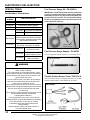
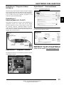
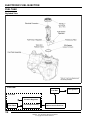
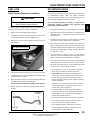
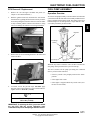
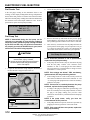
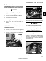
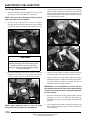
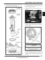
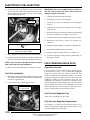
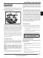
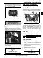
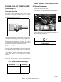
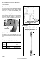
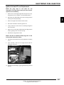
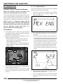
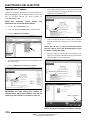
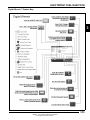
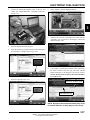
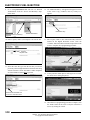
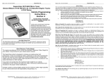
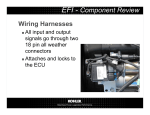
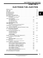
ELECTRONIC FUEL INJECTION CHAPTER 3 ELECTRONIC FUEL INJECTION SPECIAL TOOLS . . . . . . . . . . . . . . . . . . . . . . . . . . . . . . . . . . . . . . . . . . . . . . . . . . . . . . . 3.2 FUEL TANK . . . . . . . . . . . . . . . . . . . . . . . . . . . . . . . . . . . . . . . . . . . . . . . . . . . . . . . . . . . . 3.4 FUEL LINE. . . . . . . . . . . . . . . . . . . . . . . . . . . . . . . . . . . . . . . . . . . . . . . . . . . . . . . . . . . . . 3.5 EFI SERVICE NOTES . . . . . . . . . . . . . . . . . . . . . . . . . . . . . . . . . . . . . . . . . . . . . . . . . . . . 3.5 EFI SYSTEM LAYOUT . . . . . . . . . . . . . . . . . . . . . . . . . . . . . . . . . . . . . . . . . . . . . . . . . . . 3.6 EFI COMPONENTS. . . . . . . . . . . . . . . . . . . . . . . . . . . . . . . . . . . . . . . . . . . . . . . . . . . . . . 3.7 ELECTRONIC FUEL INJECTION . . . . . . . . . . . . . . . . . . . . . . . . . . . . . . . . . . . . . . . . . . . 3.9 ELECTRONIC CONTROL UNIT (ECU). . . . . . . . . . . . . . . . . . . . . . . . . . . . . . . . . . . . . . 3.10 3 ECU SERVICE . . . . . . . . . . . . . . . . . . . . . . . . . . . . . . . . . . . . . . . . . . . . . . . . . . . . . . . . 3.10 ECU REMOVAL / REPLACEMENT . . . . . . . . . . . . . . . . . . . . . . . . . . . . . . . . . . . . . . . . 3.11 FUEL PUMP ASSEMBLY . . . . . . . . . . . . . . . . . . . . . . . . . . . . . . . . . . . . . . . . . . . . . . . . 3.11 FUEL SENDER / FUEL PUMP TEST . . . . . . . . . . . . . . . . . . . . . . . . . . . . . . . . . . . . . . . 3.12 FUEL TANK REMOVAL . . . . . . . . . . . . . . . . . . . . . . . . . . . . . . . . . . . . . . . . . . . . . . . . . 3.13 FUEL PUMP REPLACEMENT . . . . . . . . . . . . . . . . . . . . . . . . . . . . . . . . . . . . . . . . . . . . 3.14 FUEL TANK INSTALLATION . . . . . . . . . . . . . . . . . . . . . . . . . . . . . . . . . . . . . . . . . . . . . 3.16 FUEL PRESSURE REGULATOR . . . . . . . . . . . . . . . . . . . . . . . . . . . . . . . . . . . . . . . . . . 3.16 FUEL INJECTORS . . . . . . . . . . . . . . . . . . . . . . . . . . . . . . . . . . . . . . . . . . . . . . . . . . . . . 3.17 FUEL INJECTOR SERVICE / TEST / REPLACEMENT. . . . . . . . . . . . . . . . . . . . . . . . . 3.17 CRANKSHAFT POSITION SENSOR (CPS) . . . . . . . . . . . . . . . . . . . . . . . . . . . . . . . . . . 3.18 CPS TEST / REPLACEMENT . . . . . . . . . . . . . . . . . . . . . . . . . . . . . . . . . . . . . . . . . . . . 3.18 TEMP / MANIFOLD ABSOLUTE PRESSURE SENSOR (T-MAP) . . . . . . . . . . . . . . . . . 3.19 T-MAP TEST / REPLACEMENT. . . . . . . . . . . . . . . . . . . . . . . . . . . . . . . . . . . . . . . . . . . 3.19 IDLE AIR CONTROL VALVE (IAC) . . . . . . . . . . . . . . . . . . . . . . . . . . . . . . . . . . . . . . . . . 3.20 IAC TEST / REPLACEMENT . . . . . . . . . . . . . . . . . . . . . . . . . . . . . . . . . . . . . . . . . . . . . 3.20 THROTTLE POSITION SENSOR (TPS) . . . . . . . . . . . . . . . . . . . . . . . . . . . . . . . . . . . . . 3.21 TPS RESISTANCE TESTS . . . . . . . . . . . . . . . . . . . . . . . . . . . . . . . . . . . . . . . . . . . . . . 3.22 TPS TESTER / REGULATOR . . . . . . . . . . . . . . . . . . . . . . . . . . . . . . . . . . . . . . . . . . . . 3.22 CHECKING TPS READING . . . . . . . . . . . . . . . . . . . . . . . . . . . . . . . . . . . . . . . . . . . . . . 3.23 TPS ADJUSTMENT . . . . . . . . . . . . . . . . . . . . . . . . . . . . . . . . . . . . . . . . . . . . . . . . . . . . 3.23 TPS REPLACEMENT . . . . . . . . . . . . . . . . . . . . . . . . . . . . . . . . . . . . . . . . . . . . . . . . . . . 3.24 ENGINE COOLANT TEMPERATURE SENSOR (ECT) . . . . . . . . . . . . . . . . . . . . . . . . . 3.25 ECT SENSOR TEST / REPLACEMENT . . . . . . . . . . . . . . . . . . . . . . . . . . . . . . . . . . . . 3.25 IGNITION COIL . . . . . . . . . . . . . . . . . . . . . . . . . . . . . . . . . . . . . . . . . . . . . . . . . . . . . . . . 3.26 IGNITION COIL TESTS . . . . . . . . . . . . . . . . . . . . . . . . . . . . . . . . . . . . . . . . . . . . . . . . . 3.26 IGNITION COIL AND HT LEAD REPLACEMENT . . . . . . . . . . . . . . . . . . . . . . . . . . . . . 3.27 EFI DIAGNOSTICS . . . . . . . . . . . . . . . . . . . . . . . . . . . . . . . . . . . . . . . . . . . . . . . . . . . . . 3.28 INSTRUMENT CLUSTER TROUBLE CODE DISPLAY . . . . . . . . . . . . . . . . . . . . . . . . . 3.28 DIGITAL WRENCH™ OPERATION . . . . . . . . . . . . . . . . . . . . . . . . . . . . . . . . . . . . . . . . 3.32 SPECIAL TOOLS / DIAGNOSTIC SOFTWARE VERSION . . . . . . . . . . . . . . . . . . . . . . 3.32 ECU REPLACEMENT / GUIDED DIAGNOSTIC AVAILABLE . . . . . . . . . . . . . . . . . . . . 3.32 DIGITAL WRENCH™ COMMUNICATION ERRORS. . . . . . . . . . . . . . . . . . . . . . . . . . . 3.32 DIGITAL WRENCH™ - DIAGNOSTIC CONNECTOR . . . . . . . . . . . . . . . . . . . . . . . . . . 3.33 DIGITAL WRENCH™ VERSION AND UPDATE ID . . . . . . . . . . . . . . . . . . . . . . . . . . . . 3.33 DIGITAL WRENCH™ SERIAL NUMBER LOCATION . . . . . . . . . . . . . . . . . . . . . . . . . . 3.33 DIGITAL WRENCH™ UPDATES . . . . . . . . . . . . . . . . . . . . . . . . . . . . . . . . . . . . . . . . . . 3.34 DIGITAL WRENCH™ FEATURE MAP. . . . . . . . . . . . . . . . . . . . . . . . . . . . . . . . . . . . . . 3.35 ENGINE CONTROLLER REPROGRAMMING (REFLASH). . . . . . . . . . . . . . . . . . . . . . 3.36 FUEL SYSTEM TROUBLESHOOTING. . . . . . . . . . . . . . . . . . . . . . . . . . . . . . . . . . . . . . 3.39 EFI SYSTEM BREAK-OUT DIAGRAM . . . . . . . . . . . . . . . . . . . . . . . . . . . . . . . . . . . . . . 3.40 3.1 9923067 - 2011 Sportsman 850 Service Manual © Copyright 2010 Polaris Sales Inc. ELECTRONIC FUEL INJECTION SPECIAL TOOLS Fuel Pressure Gauge Kit - PU-43506-A Part Numbers / Descriptions PART NUMBER TOOL DESCRIPTION PU-43506-A Fuel Pressure Gauge Kit PS-48762 Fuel Pressure Gauge Adaptor 2201519-A Throttle Position Sensor (TPS) Tester PU-47466 TPS Tester Wire Harness 547927 TPS Tester Regulator IMPORTANT: The EFI fuel system remains under high pressure, even when the engine is not running. Before attempting to service any part of the fuel system, the pressure must be relieved. The Fuel Pressure Gauge Kit has an integrated pressure relief valve that can be used to bleed off pressure. Relief Valve Digital Wrench™ Diagnostic Software (Includes most recent version of software PU-47063-A w/serial number, standard interface cable and SmartLink Module Kit) PU-47471 Digital Wrench™ SmartLink Module Kit (PU-47470, PU-47469, PU-47468) PU-47470 Digital Wrench™ PC Interface Cable PU-47469 Digital Wrench™ Vehicle Interface Cable PU-47468 Digital Wrench™ SmartLink Module Adaptor shown is included with kit. Fuel Pressure Gauge Adaptor - PS-48762 Used in conjunction with PU-43506-A to check fuel pressure. 7/16-20 Schrader WARNING * Gasoline is extremely flammable and explosive under certain conditions. * EFI components are under high pressure. Verify system pressure has been relieved before disassembly. * Never drain the fuel system when the engine is hot. Severe burns may result. * Do not overfill the tank. The tank is at full capacity when the fuel reaches the bottom of the filler neck. Leave room for expansion of fuel. * Never start the engine or let it run in an enclosed area. Gasoline powered engine exhaust fumes are poisonous and can cause loss of consciousness and death in a short time. * Do not smoke or allow open flames or sparks in or near the area where refueling is performed or where gasoline is stored. * If you get gasoline in your eyes or if you should swallow gasoline, seek medical attention immediately. * If you spill gasoline on your skin or clothing, immediately wash with soap and water and change clothing. * Always stop the engine and refuel outdoors or in a well ventilated area. Throttle Position Sensor Tester - 2201519-A This tester allows the use of a digital multi-meter to test TPS function and perform the “TPS Adjustment” procedure. 3.2 9923067 - 2011 Sportsman 850 Service Manual © Copyright 2010 Polaris Sales Inc. ELECTRONIC FUEL INJECTION Digital Wrench™ Diagnostic Software PU-47063-A Digital Wrench™ - Download Website Located at: www.polaris.diagsys.com This dealer-only software installs on laptop computers equipped with a CD drive and serial port connection, and is designed to replace multiple shop tools often used to test EFI components. It also includes step-by-step diagnostic procedures to aid technician repair and troubleshooting. Digital Wrench™ SmartLink Module Kit - PU-47471 This module kit contains the necessary cables and hardware to communicate between the vehicle ECU and the Digital Wrench™ diagnostic software. Polaris dealers can also order the following separately: SmartLink Module PU-47468, Vehicle Interface Cable PU-47469 and PC Interface Cable PU47470. This kit is available to Polaris dealers through our tool supplier, SPX (1-800-328-6657). 3 Download Digital Wrench Updates: PU-47469 PU-47468 PU-47470 IMPORTANT: For the most recent information on Digital Wrench™ software and update downloads please visit the website: www.polaris.diagsys.com Digital Wrench™ - Diagnostic Connector The diagnostic connector is located under the front rack, in front of the battery as shown. 3.3 9923067 - 2011 Sportsman 850 Service Manual © Copyright 2010 Polaris Sales Inc. ELECTRONIC FUEL INJECTION FUEL TANK Exploded View Fuel Flow Fuel Rail Fuel Tank Pressure Regulator Fuel Filters Fuel Pump Assembly Quick Connect Fuel Line 3.4 9923067 - 2011 Sportsman 850 Service Manual © Copyright 2010 Polaris Sales Inc. Fuel Injectors ELECTRONIC FUEL INJECTION FUEL LINE EFI SERVICE NOTES Quick Connect Removal / Installation For more convenient and accurate testing of EFI components, it is recommended dealers utilize the Digital Wrench™ Diagnostic Software (dealer only), or limited testing may be done manually using the procedures provided. CAUTION Verify fuel system has been depressurized before performing this procedure. 80% of all EFI problems are caused by wiring harness connections. Follow a common sense approach when diagnosing a potential EFI issue: All EFI models use quick connect fuel lines. Refer to the following steps for fuel line removal / installation: 1. Disconnect the harness at the suspected sensor connector. 1. Remove the seat and upper right side panel. 2. 2. Thoroughly clean the connector and place a shop towel around the fuel line to catch any dripping fuel. Inspect the connector ends for damage or contamination. If damaged, repair; if contaminated, clean. Reconnect and check function. 3. 3. Squeeze the connector tabs together and pull out on the white retainer. If problem persists, perform a sensor bench test according to the specific sensor requirements (if applicable). 4. If the sensor bench tests pass, disconnect the connector at the ECU and perform a continuity check between the sensor connector and the appropriate pin at the ECU connector (all connections for that sensor). Wiring resistance should be less than one (1) ohm. 5. If the resistance is high (or open), a wiring harness inspection is required (including a thorough inspection of the ECU connector for contamination or damage). 6. If the sensor passes and the wiring passes inspection, and reconnecting the ECU does not resolve the issue, then at that point a known-good ECU (from another Polaris 850) may be used to test for problem resolution. Push tabs in and pull out white retainer before removing 4. Lift up on the fuel line and remove it from the pump outlet. 5. To install the line, verify the connector and fuel pump outlet are clean and free of debris. 6. Place the connector end over the fuel pump outlet and push the white retainer and tabs back into place. NOTE: Confirm attachment by pulling on the fuel line. 7. Repeat this process when removing the fuel line from the fuel rail. Fuel Pump Outlet • Never attempt to service any fuel system component while engine is running or ignition switch "on". • USE CARE when removing or installing the ECU connector, as well as all other harness connections on the unit. Properly connect and disconnect the ECU harness to minimize damage to the connector pins and locking mechanism. • Although every precaution has been taken to prevent water intrusion failure, avoid direct water or spray contact with system components. • Do not disconnect or reconnect the wiring harness connector to the ECU or any individual components with the ignition "on." This can send a damaging voltage spike through the ECU. • Do not allow battery cables to touch opposite terminals. • Never start the engine when the cables are loose or poorly connected to the battery terminals. • Never disconnect battery while engine is running. Fuel Rail • Always unplug ECU from the wire harness before performing any welding on the unit. 3.5 9923067 - 2011 Sportsman 850 Service Manual © Copyright 2010 Polaris Sales Inc. 3 ELECTRONIC FUEL INJECTION EFI SYSTEM LAYOUT Exploded View 1. Electronic Control Unit (ECU) 2. Temperature / Manifold Absolute Pressure Sensor (T-MAP) 3. Idle Air Control (IAC) 4. Crankshaft Position Sensor (CPS) 5. Fuel Injectors 6. Fuel Rail 7. Fuel Line (quick connect) 8. Fuel Pump / Regulator / Fuel Gauge Sender (inside fuel tank) 9. Engine Coolant Temperature Sensor (ECT) 10. Throttle Position Sensor (TPS) 11. Throttle Body 12. Ignition Coil 1 12 3 5 6 7 2 10 4 11 8 9 Located in the Fuel Tank Asm. 3.6 9923067 - 2011 Sportsman 850 Service Manual © Copyright 2010 Polaris Sales Inc. ELECTRONIC FUEL INJECTION EFI COMPONENTS 4. Identification / Location 1. Electronic Control Unit (ECU) - Attached to the air box, located behind the LH side panel. Crankshaft Position Sensor (CPS) - Located in the top portion of the magneto cover on the front of the engine. CPS 3 ECU 5. 2. Temperature and Manifold Absolute Pressure Sensor (T-MAP) - Located in the Integrated Air Fuel Manifold (IAFM). Fuel Injectors - Located in the Integrated Air Fuel Manifold (IAFM). Fuel Rail T-MAP Pressure Valve 3. Idle Air Control (IAC) - Located in front of the engine, under the airbox. PTO Fuel Injector 6. Fuel Rail / Fuel Pressure Valve - Attached to the top portion of the fuel injectors. - Located on the PTO end of the fuel rail. 7. Fuel Line (Quick Connect) - Located between the injector fuel rail and the fuel tank. Fuel Pump Outlet IAC Fuel Rail 3.7 9923067 - 2011 Sportsman 850 Service Manual © Copyright 2010 Polaris Sales Inc. ELECTRONIC FUEL INJECTION 8. Fuel Pump / Regulator / Fuel Gauge Sender Assembly - Located behind the right-hand side panel. 10. Throttle Position Sensor (TPS) - Located on the MAG end (front) of the throttle body. TPS Fuel Pump - Located in the fuel tank as an assembly. 11. Throttle Body - Attached between the IAFM and the intake plenum. Throttle Body IAFM Intake Plenum Fuel Pump Assembly 12. Ignition Coil - Located on the RH side of the airbox. The high tension leads are retained by the airbox. 9. Engine Coolant Temperature Sensor (ECT) - Located in the cylinder head below the thermostat housing, just above the throttle body. ECT Ignition Coil 3.8 9923067 - 2011 Sportsman 850 Service Manual © Copyright 2010 Polaris Sales Inc. ELECTRONIC FUEL INJECTION ELECTRONIC FUEL INJECTION General Information The Electronic Fuel Injection (EFI) system is a complete engine fuel and ignition management design. This system includes the following principal components: • Fuel Pump / Fuel Filters / Pressure Regulator • Fuel Line • Fuel Rail The ECU controls the amount of fuel being injected and the ignition timing by monitoring the primary sensor signals for intake air temperature, manifold absolute pressure (load), engine temperature, speed (RPM), and throttle position. These primary signals are compared to the programming in the ECU computer chip, and the ECU adjusts the fuel delivery and ignition timing to match the values. During operation the ECU has the ability to re-adjust temporarily, providing compensation for changes in overall engine condition and operating environment, so it will be able to maintain the ideal air/fuel ratio. • Fuel Injectors • Throttle Body / lntegrated Air Fuel Manifold (IAFM) • Electronic Control Unit (ECU) During certain operating periods such as cold starts, warm up, acceleration, etc., a richer air / fuel ratio is automatically calculated by the ECU. • Ignition Coil • Engine Coolant Temperature Sensor (ECT) Initial Priming / Starting Procedure • Throttle Position Sensor (TPS) NOTE: The injection system must be purged of all air prior to the initial start up, and / or any time the system has been disassembled. • Crankshaft Position Sensor (CPS) • Intake Air Temperature / Manifold Absolute Pressure Sensor (T-MAP) • Idle Air Control (IAC) • Wire Harness Assembly If the EFI system is completely empty of fuel or has been disassembled and repaired: 1. EFI Operation Overview 2. The EFI system is designed to provide peak engine performance with optimum fuel efficiency and lowest possible emissions. The ignition and injection functions are electronically controlled, monitored and continually corrected during operation to maintain peak performance. The central component of the system is the Bosch Electronic Control Unit (ECU) which manages system operation, determining the best combination of fuel mixture and ignition timing for the current operating conditions. 3. Cycle the key switch from “OFF” to “ON” 6 times, waiting for approximately 3 seconds at each “ON” cycle to allow the fuel pump to cycle and shut down. Once step 1 is completed, turn the key switch to “START” until the engine starts or 5 seconds has passed. If the engine failed to start, repeat step 1 for 2 more cycles and attempt to start the engine. If the engine fails to start, a problem may still exist, and should be diagnosed. NOTE: Accurate testing of EFI components is recommended utilizing the Digital Wrench™ Diagnostic Software (dealer only). An in-tank electric fuel pump is used to move fuel from the tank, through the fuel line, to the fuel rail. The in-tank fuel pressure regulator maintains a system operating pressure of 43 psi and returns any excess fuel to the tank. At the engine, fuel is fed through the fuel rail and into the injectors, which inject into the intake ports. The ECU controls the amount of fuel by varying the length of time that the injectors are "on." This can range from 1.5-8.0 milliseconds depending on fuel requirements. The controlled injection of the fuel occurs every other crankshaft revolution, or once for each 4-stroke cycle. The total amount of fuel needed for one firing of a cylinder is injected during each cycle. When the intake valve opens, the fuel/air mixture is drawn into the combustion chamber, ignited and burned. 3.9 9923067 - 2011 Sportsman 850 Service Manual © Copyright 2010 Polaris Sales Inc. 3 ELECTRONIC FUEL INJECTION ELECTRONIC CONTROL UNIT (ECU) Operation Overview The ECU is the brain or central processing computer of the entire EFI fuel/ignition management system. During operation, sensors continuously gather data which is relayed through the wiring harness to input circuits within the ECU. Signals to the ECU include: ignition (on/off), crankshaft position and speed (RPM), throttle position, engine coolant temperature, intake air temperature, intake manifold air pressure and battery voltage. To prevent engine over-speed and possible failure, an RPMlimiting feature is programmed into the ECU. If the maximum RPM limit (8000) is exceeded, the ECU suppresses the injection signals, cutting off the fuel flow. This process repeats it self in rapid succession, limiting operation to the preset maximum. Maximum RPM Limit: 8000 SPORTSMAN 850 RPM Limit: Hard Limit - Fuel injector suppression occurs The ECU compares the input signals to the programmed maps in its memory and determines the appropriate fuel and spark requirements for the immediate operating conditions. The ECU then sends output signals to set the injector duration and ignition timing. • All Gears: 8000 RPM Soft Limit - Spark timing suppression occurs • All Gears: 7500 RPM ECU Service Never attempt to disassemble the ECU. It is sealed to prevent damage to internal components. Warranty is void if the case is opened or tampered with in any way. All operating and control functions within the ECU are pre-set. No internal servicing or readjustment may be performed. If a problem is encountered, and you determine the ECU to be faulty, contact the Polaris Service Department for specific handling instructions. Do not replace the ECU without factory authorization. During operation, the ECU continually performs a diagnostic check of itself, each of the sensors, and system performance. If a fault is detected, the ECU turns on the “Check Engine” light in the speedometer and stores the fault code in its fault memory. Depending on the significance or severity of the fault, normal operation may continue, or "Fail-Safe" operation (slowed speed, richer running) may be initiated. A technician can determine the cause of the “Check Engine” light by referencing the “Instrument Cluster Trouble Code Display” and “Diagnostic Trouble Code Table” or by using Digital Wrench™. The ECU requires a minimum of 7.0 volts to operate. The memory in the ECU is operational the moment the battery cables are connected. The relationship between the ECU and the throttle position sensor (TPS) is very critical to proper system operation. If the TPS is faulty, or the mounting position of the TPS to the throttle body is altered, the TPS must be adjusted. For the purpose of troubleshooting, a known-good ECU from another Polaris Sportsman 850 of the same model may be used without system or engine component damage. 3.10 9923067 - 2011 Sportsman 850 Service Manual © Copyright 2010 Polaris Sales Inc. ELECTRONIC FUEL INJECTION ECU Removal / Replacement FUEL PUMP ASSEMBLY 1. Remove the seat and upper left-hand side panel (see Chapter 9 “Seat and Side Panels”). Operation Overview 2. With the ignition turned off, disconnect the wire harness from the ECU by pulling the black slider out away from the ECU while pulling down on the connector. Once the slider is fully extended, pull the connector from the ECU, using care not to damage the connector or locking mechanism. An electric fuel pump assembly is used to transfer fuel to the EFI system from inside the fuel tank. This assembly includes the fuel pump, regulator and fuel gauge sender. The pump is rated for a minimum output of 25 liters per hour at 43 psi and has a nonserviceable preliminary 60-micron filter. 3 Regulator Fuel Gauge Sender Fuel Gauge Float Arm 3. Remove the (4) screws retaining the ECU to the airbox and remove the ECU. Fuel Pump Preliminary Filter 60-micron When the key switch is turned to "ON", the ECU activates the fuel pump, which pressurizes the system for start-up. The ECU switches off the pump preventing the continued delivery of fuel in these instances: • If the key switch is not promptly turned to the "Start" position. • If the engine fails to start. • If the engine is stopped with the key switch "ON" (as in the case of an accident). 4. To install, reverse the previous steps. DO NOT apply dielectric grease to the connector, as it is a sealed connector. Tighten screws to 10 in. lbs. (1.1 Nm). =T ECU Retaining Screws 10 in. lbs. (1.1 Nm) IMPORTANT: If replacing the ECU, you must reflash the new ECU with the correct calibration upon installation and prior to attempting to start the vehicle. 3.11 9923067 - 2011 Sportsman 850 Service Manual © Copyright 2010 Polaris Sales Inc. ELECTRONIC FUEL INJECTION Fuel Sender Test 2. Locate the fuel pressure valve attached to the fuel rail. If the fuel gauge reading on the instrument cluster is not working, or if the display reading differs in large comparison to the fuel in the tank, perform a resistance test on the fuel sender. Disconnect the fuel pump / sending unit connection and measure the resistance between the Purple and Brown wires. If out of specification, replace the fuel pump assembly. Pressure Valve Fuel Sender Resistance Specifications: Full: 6 ± 1 Empty: 90 ± 4.5 Fuel Pump Test NOTE: If determined faulty, the fuel pump can be replaced as an assembly. If a fuel delivery problem is suspected, make certain the pump is being activated by the ECU and EFI relay, all electrical connections are properly secured, the 20A EFI fuse is good, and a minimum of 7.0 volts is being supplied. 3. Remove the black cap and attach the fuel pressure gauge kit and adaptor to the pressure valve. Route the clear hose into a portable gasoline container or the vehicle’s fuel tank. 4. Turn on the key switch to activate the pump and check the system pressure on the gauge. If system pressure of 43 psi 3 is observed, turn the key switch “off” and depress the valve button on the tester to relieve the system pressure. CAUTION Fuel Pump Pressure: 43 psi 3 Fuel is extremely flammable and may cause severe burns, injury, or death. Do not use any device that produces a flame or electrical devices that may spark around fuel or fuel vapors. 1. NOTE: If the fuel pressure is out of specification, replace the fuel pump assembly. 5. Couple the Fuel Pressure Gauge Adaptor (PS-48762) to the Fuel Pressure Gauge Kit (PU-43506-A). If the pump did not activate (Step 4), disconnect the plug from the fuel pump. Connect a DC voltmeter across terminals “A” and “C” in the plug on the vehicle harness side. Turn on the key switch and observe voltage to ensure a minimum of 7 volts is present. NOTE: If the voltage was below 7 VDC, test battery, ignition switch, EFI relay and wiring harness. PU-43506-A 6. Relief Valve If the reading is between 7 and 14 volts, turn key switch off and connect an ohmmeter between the terminals “A” and “C” in the plug on the pump harness to check for continuity within the fuel pump. NOTE: If there was no continuity between the pump terminals, replace the fuel pump assembly. 7. Adaptor shown is included with kit. PS-48762 NOTE: If the pump starts, verify you have the correct amount of fuel pressure. 8. 7/16-20 Schrader If voltage at the plug was within the specified range, and there was continuity across the pump terminals, reconnect the plug to the pump, making sure you have clean connections. Turn on the key switch and listen for the pump to activate. If the pump still does not operate, check ECU operation by plugging in a known-good ECU of the same model. NOTE: If the pump still does not operate, replace the fuel pump assembly. 3.12 9923067 - 2011 Sportsman 850 Service Manual © Copyright 2010 Polaris Sales Inc. ELECTRONIC FUEL INJECTION Fuel Tank Removal 9. Disconnect the fuel pump electrical harness. IMPORTANT: Syphon as much fuel from the tank as possible before attempting to remove it from the ATV. Pump Harness Fuel Line Connector WARNING Always wear safety goggles when working with high pressure or flammable fluids. Failure to do so could result in serious injury or complications. 1. Remove the seat and upper side panels (see Chapter 9). 2. Disconnect the negative battery cable. 3. Remove the (4) push rivets from each front mud guard and remove the guards from the vehicle (see Chapter 9). 4. Remove the front rack or storage box assembly (see Chapter 9). 5. Remove the front cab assembly (see Chapter 9). IMPORTANT: Be sure to cover the fuel tank inlet with a shop towel prior to front cab and fuel tank removal (see Chapter 9 “Front Cab”). 6. Remove the (4) screws from the bottom of the right-hand footwell. 7. Remove the (2) fuel tank mounting screws located on the upper portion of the fuel tank. 3 10. While holding a shop towel over the fuel line connector, disconnect the quick connect fuel line from the fuel pump. CAUTION It is possible for pressurized fuel to be present when disconnecting the fuel line. It is recommended to allow the vehicle to sit for a period of one hour after shutting off the engine before servicing the fuel pump. This allows the exhaust to cool and fuel pressure to drop. NOTE: A small amount of fuel may come out of the fuel line or tank. Properly drain fuel into a suitable container. 11. If replacing the fuel pump, carefully pull the fuel tank out far enough to service the fuel pump (see “Fuel Pump Replacement” procedure). If removing fuel tank assembly, proceed to the next step. 12. Remove the vent line from the fitting on top of the fuel tank. 8. Ensure that static has been discharged from you by touching a ground source such as the engine or frame. Vent Fitting 13. Carefully pull the fuel tank out the right side of the ATV. 3.13 9923067 - 2011 Sportsman 850 Service Manual © Copyright 2010 Polaris Sales Inc. ELECTRONIC FUEL INJECTION Fuel Pump Replacement 1. 4. Carefully lift the fuel pump out of the fuel tank. As the fuel pump assembly is being removed, be aware of float arm and pump pre-filter. Hold the float arm to the pump body as you lift and tilt the pump to ensure that the float arm is not bent when removed from the tank. 5. Transfer old fuel pump to a suitable container capable of safely holding fuel. The fuel pump will retain some fuel. 6. Inspect the inside of the fuel tank for debris (may require flashlight and mirror). If debris like mud or sand is present, fuel tank should be flushed and cleaned out prior to installation of new fuel pump assembly. Slide the fuel tank out to allow enough access to service the fuel pump (see “Fuel Tank Removal” procedure). NOTE: Take care not to damage the Idle Air Control (IAC) valve upon fuel tank removal. 2. Be sure the top of the fuel tank is clean. If it requires cleaning, hand wash the top of the tank to ensure no debris will enter the fuel system when the fuel pump is removed. Clean this area CAUTION Failure to clean area around fuel pump may lead to debris entering the fuel tank during service. Excessive debris in fuel tank may cause premature wear of fuel pump and/or clogging of internal fuel filters. 3. Place the Fuel Pump Service Tool (PU-50326) over the fuel pump PFA nut. Using a 1/2” drive ratchet or breaker bar, loosen and remove the PFA nut. Discard the PFA nut. IMPORTANT: It is recommended to remove the fuel tank from the vehicle and rinse it with a small amount of clean fuel. Do not use water or any other chemicals to remove debris. 7. Remove new fuel pump assembly, gasket and PFA nut from packaging. Use care not to bend float arm during unpackaging. Do not lift or carry fuel pump assembly by the float arm. 8. Use cleaning wipes provided to clean fuel tank surface and threads. Remove all debris, grease and oil. Allow surfaces to dry completely. PFA Nut PU-50326 NOTE: Apply downward force on the fuel pump flange while removing the fuel pump PFA nut. 3.14 9923067 - 2011 Sportsman 850 Service Manual © Copyright 2010 Polaris Sales Inc. ELECTRONIC FUEL INJECTION 9. Install new PFA gasket onto fuel pump assembly using care not to damage gasket or bend float arm. 10. Install fuel pump into fuel tank, hold float arm to the pump body and tilt assembly to ensure float arm does not get caught or bent during installation. 11. Gently push down on fuel pump flange ensuring flange is centered. 3 Center and align fuel pump flange 12. Roughly align orientation mark on fuel pump with orientation mark on fuel tank to ensure float arm does not get bent or snagged. CAUTION Failure to align the orientation marks may lead to interferences with the fuel level float arm and cause incorrect function. 13. While maintaining downward pressure, thread new PFA nut onto fuel tank and hand tighten. Use care when starting PFA nut, ensuring threads are properly aligned. Verify orientation marks are still aligned between fuel pump and fuel tank. 3.15 9923067 - 2011 Sportsman 850 Service Manual © Copyright 2010 Polaris Sales Inc. ELECTRONIC FUEL INJECTION 14. Torque PFA nut to specification using the Fuel Pump Service Tool (PU-50326) and a calibrated torque wrench. Hold or support the fuel tank to prevent it from rotating while tightening the PFA nut. 70 ± 5 ft. lbs. (95 ± 7 Nm) =T 3. Connect the fuel pump electrical harness. 4. Reinstall the vent line to the tank fitting. 5. Install the (2) fuel tank mounting screws and tighten securely. 6. Install the (4) screws into the bottom portion of the righthand footwell. 7. Remove the shop towel from the fuel tank inlet and reinstall the front cab assembly (see Chapter 9 “Front Cab”). 8. Connect the fuel fill hose and tighten hose clamp securely. 9. Reinstall the front rack or storage box assembly (see Chapter 9). 10. Install the front mud guards (see Chapter 9 “Mud Guards”). 11. Reconnect the negative cable to the battery. Fuel Pump PFA Nut: 70 ± 5 ft. lbs. (95 ± 7 Nm) 12. Install the upper side panels and seat (see Chapter 9). 15. Verify alignment of fuel pump and tank orientation marks. 16. Carefully slide the fuel tank back into position. Ensure vent line has not been pinched during installation of fuel tank. NOTE: Take care not to damage the Idle Air Control (IAC) valve upon fuel tank installation. 17. Refer to “Fuel Tank Installation” to complete the repair. Fuel Tank Installation 1. Reinstall the fuel tank assembly through the right side. Be sure the tabs on the bottom of the fuel tank are sitting in the slots of the support bracket. 2. Connect the fuel line to the fuel pump outlet. Press in white retainer to engage the tabs IMPORTANT: Be sure to engage the white retainer on fuel line until it snaps into place. Pull on fuel line lightly to confirm connection. 13. Test the fuel pump by turning on the key and listening for the pump to activate. FUEL PRESSURE REGULATOR Operation Overview The fuel pressure regulator maintains the required operating system pressure of 43 psi ± 3 psi. A rubber-fiber diaphragm divides the regulator into two separate sections, the fuel chamber and the pressure regulating chamber. The pressure regulating spring presses against the valve holder (part of the diaphragm), pressing the valve against the valve seat. The combination of atmospheric pressure and regulating spring tension equals the desired operating pressure. Any time the fuel pressure against the bottom of the diaphragm exceeds the desired (top) pressure, the valve opens, relieving the excess pressure, returning the excess fuel back to the tank. Fuel Pressure Regulator Test Refer to the “Fuel Pump Test” procedure. Fuel Pressure Regulator Replacement The regulator is a sealed, non-serviceable assembly. If it is faulty, the fuel pump assembly must be replaced. Refer to the “Fuel Pump Replacement” procedure. 3.16 9923067 - 2011 Sportsman 850 Service Manual © Copyright 2010 Polaris Sales Inc. ELECTRONIC FUEL INJECTION FUEL INJECTORS Operation Overview The fuel injectors mount into the Integrated Air Fuel Manifold (IAFM), and the fuel rail attaches to the top end of them. O-rings on both ends of the injector prevent external fuel leaks and also insulate it from heat and vibration. Pressure Valve Damper Fuel Injectors Injector leakage is very unlikely, but in rare instances it can be internal (past the tip of the valve needle), or external (weeping around the injector body). The loss of system pressure from the leakage can cause hot restart problems and longer cranking times. Injector problems due to dirt or clogging are unlikely due to the design of the injectors, the high fuel pressure, the use of filters and the detergent additives in the gasoline. Symptoms that could be caused by dirty/clogged injectors include rough idle, hesitation/stumble during acceleration, or triggering of fault codes related to fuel delivery. Injector clogging is usually caused by a buildup of deposits on the director plate, restricting the flow of fuel, resulting in a poor spray pattern. Some contributing factors to injector clogging include; dirty air filters, higher than normal operating temperatures, short operating intervals and dirty, incorrect, or poor quality fuel. Cleaning of clogged injectors is not recommended; they should be replaced. Additives and higher grades of fuel can be used as a preventative measure if clogging has been a problem. Fuel Injector Test When the key switch is on, the fuel rail is pressurized, and the EFI relay provides voltage to the injectors. During engine operation, the ECU completes the ground circuit, energizing the injectors. The valve needle in the injector is opened electromagnetically, and the pressure in the fuel rail forces fuel down through the inside. The “director plate” at the tip of the injector contains a series of calibrated openings which directs the fuel into the intake port in a cone-shaped spray pattern. If an injector is not operating, it can indicate either a bad injector, or a wiring/electrical connection problem. Check as follows: The amount of fuel injected is controlled by the ECU and determined by the length of time the valve needle is held open, also referred to as the “injection duration” or “pulse width”. It may vary in length depending on the speed and load requirements of the engine. • Resistance specification is 12 ± 5% (20°C, 68°F) • Remove the seat, left-hand side panel, and disconnect the fuel injector(s). • Using an ohmmeter, test for continuity by placing the test leads on each pin of the injector. Fuel Injector Resistance Specification: 12 ± 5% (20°C, 68°F) Fuel Injector Service Fuel Injector Replacement Injector problems typically fall into three general categorieselectrical, dirty / clogged, or leakage. An electrical problem usually causes one or both of the injectors to stop functioning. Several methods may be used to check if the injectors are operating. NOTE: Engine must be cool. Depressurize the fuel system if possible. 1. Remove the seat and both upper side panels (see Chapter 9 “Seat and Side Panels”). NOTE: Do not apply voltage directly to the fuel injectors. Excessive voltage will burn out the injectors. Do not ground the injectors with the ignition on. The injectors will open if the EFI relay is energized. 2. Remove the (2) screws retaining the lower portion of the air box. 3. Remove the hose from the breaker valve located on top of the valve cover. 4. Remove the spark plug wires. 5. Remove the (2) Torx-head screws retaining the upper portion of the air box to the front cab. If an injector is not operating, it can indicate either a bad injector, or a wiring/electrical connection problem. Check as follows: 3.17 9923067 - 2011 Sportsman 850 Service Manual © Copyright 2010 Polaris Sales Inc. 3 ELECTRONIC FUEL INJECTION 6. Carefully disconnect the ECU by pulling the tab out while pulling down on the connector. 7. Loosen the hose clamp retaining the intake boot to the intake plenum and remove the boot. 8. Lift up on the air box and turn it sideways to gain access to the fuel rail and fuel injectors. 9. Thoroughly clean the area around the fuel rail and injectors. CRANKSHAFT POSITION SENSOR (CPS) Operation Overview The crankshaft position sensor is essential to engine operation, constantly monitoring the rotational speed (RPM) and position of the crankshaft. 10. Disconnect the “quick connect” fuel line from the fuel rail. 11. Disconnect the harness from both fuel injectors. 12. Using a 10 mm wrench, remove the fuel rail mounting screws. CPS “Removed” 13. Carefully pull up on the fuel rail and fuel injectors and remove them from the vehicle as an assembly. A ferromagnetic 60-tooth ring gear with two consecutive teeth missing is mounted on the flywheel. The inductive speed sensor is mounted 1.0 0.26 mm (0.059 0.010 in.) away from the ring gear. During rotation, an AC pulse is created within the sensor for each passing tooth. The ECU calculates engine speed from the time interval between the consecutive pulses. The two-tooth gap creates an “interrupt” input signal, corresponding to specific crankshaft position. This signal serves as a reference for the control of ignition timing by the ECU. Synchronization of the CPS and crankshaft position takes place during the first two revolutions each time the engine is started. This sensor must be properly connected at all times. If the sensor fails or becomes disconnected for any reason, the engine will stop running. Fuel Rail Injectors 14. Pry the two injector retaining tabs open and remove the injector(s) from the fuel rail. CPS Test The crankshaft position sensor is a sealed, non-serviceable assembly. If fault code diagnosis indicates a problem with the CPS, test and correct as follows: 1. Remove the seat and left-hand side panel. 2. Locate and disconnect the CPS harness connector on the left side of the vehicle just below the ECU. 15. Lubricate the O-rings lightly with soapy water to aid installation of the new injector(s). Disconnect 16. Install the new injector(s) and torque the fuel rail mounting screws to 6 - 9 ft. lbs. (8 - 12 Nm). 3.18 9923067 - 2011 Sportsman 850 Service Manual © Copyright 2010 Polaris Sales Inc. ELECTRONIC FUEL INJECTION 3. Connect an ohmmeter between the pin terminals as shown. A resistance value of 860 10% at room temperature (20 C, 68 F) should be obtained. TEMP / MANIFOLD ABSOLUTE PRESSURE SENSOR (T-MAP) Operation Overview CPS Connector Mounted on the IAFM, the temperature and manifold absolute pressure sensor (T-MAP) performs two functions in one unit. 3 Measure resistance at these two pins 4. If resistance is correct, check the mounting, toothed ring gear (damage, runout, etc.), and flywheel key. Crankshaft Position Sensor: 860 10% (20 C, 68 F) CPS Replacement 1. Disconnect sensor harness connector (see “CPS Test”). 2. Using a 6 mm hex wrench, remove the retaining bolt and remove the sensor from the magneto cover. T-MAP Air passing through the intake is measured by the T-MAP and relayed to the ECU. These signals, comprised of separate air temperature and manifold absolute pressure readings, are processed by the ECU and compared to its programming for determining the fuel and ignition requirements during operation. T-MAP Test CPS The temperature and manifold absolute pressure sensor (T-MAP) is a non-serviceable item. If it is faulty, it must be replaced. This sensor requires a 5 Vdc input to operate, therefore the T-MAP sensor should only be tested using the Digital Wrench™ Diagnostic Software (dealer only). T-MAP Replacement 1. Disconnect the sensor from the main harness. 2. Using a 10 mm wrench, remove the retaining bolt and sensor. 3. Install the new sensor using a light coating of oil on the Oring to aid installation. 3. Install the new sensor using a light coating of oil on the Oring to aid installation. 4. Torque the retaining bolt to specification. 4. Torque the retaining bolt to specification. =T =T CPS Retaining Bolt Torque: 7 ft. lbs. (10 Nm) T-MAP Retaining Bolt Torque: 35-53 in. lbs. (4-6 Nm) 3.19 9923067 - 2011 Sportsman 850 Service Manual © Copyright 2010 Polaris Sales Inc. ELECTRONIC FUEL INJECTION IDLE AIR CONTROL VALVE (IAC) IAC Replacement Operation Overview 1. Remove the seat, upper side panels and front cab (see Chapter 9). The Idle Air Control (IAC) is used to stabilize the idle quality of the engine at cold start-up and after warm-up operations. 2. Remove the (2) screws retaining the airbox to the frame. 3. Disconnect the main vehicle harness from the ECU and ignition coil located on either side of the airbox. IAC Ignition Coil ECU Mounted in front of the engine, the IAC contains 1 stepper motor which receives varying voltage signal pulses from the ECU. These pulses determine the IAC plunger setting, thereby controlling the amount of air bypassing the closed throttle body for idle control. If the IAC is disconnected or inoperative, it will remain at it’s last operated position. 4. Disconnect the shift linkage from the shift lever. 5. Remove the spark plug wires 6. Remove the breather hose from the valve cover breather. IAC Test The IAC is a non-serviceable item. If it is faulty, it must be replaced. It can be ‘bench tested’ using the following method: Set your meter to read Ohms. Check the resistance values at each of the following pin locations of the IAC. If any of the readings are out of specification, replace the IAC. Remove Disconnect IAC Valve Connector Remove 4 5 6 1 2 3 7. Loosen the clamp and remove the intake boot from the intake plenum. 8. Remove the airbox assembly from the vehicle. IAC Resistance Readings Pins Resistance Pins Resistance 1-2 30 ± 1.2 4-5 30 ± 1.2 2-3 30 ± 1.2 5-6 30 ± 1.2 1-3 60 ± 2.4 4-6 60 ± 2.4 3.20 9923067 - 2011 Sportsman 850 Service Manual © Copyright 2010 Polaris Sales Inc. ELECTRONIC FUEL INJECTION 9. Remove the screw retaining the IAC sensor to the frame. THROTTLE POSITION SENSOR (TPS) Operation Overview Remove The throttle position sensor (TPS) is used to indicate throttle plate angle to the ECU. IAC TPS Throttle Body 3 10. Move the IAC out from the frame and disconnect the vehicle harness from sensor. 11. Remove the (3) Phillips-head mounting screws and remove the sensor from the housing. Mounted on the throttle body and operated directly off the end of the throttle shaft, the TPS works like a rheostat, varying the voltage signal to the ECU in direct correlation to the angle of the throttle plate. This signal is processed by the ECU and compared to the internal pre-programmed “maps” to determine the required fuel and ignition settings for the amount of engine load. 12. Install the new IAC sensor and torque the mounting screws to 17.7 in. lbs. (2 Nm). The correct position of the throttle body stop screw is established and set at the factory. DO NOT remove the tamper proof cap to adjust the throttle body stop screw or alter its position in any manner. The stop screw controls the air flow calibration of the throttle body. =T IAC Mounting Screw Torque: 17.7 in. lbs. (2 Nm) Throttle Body 13. Reconnect vehicle harness to IAC. 14. Reinstall the IAC retaining screw and tighten securely. 15. Reinstall the airbox, attach the intake boot to the intake plenum and tighten the clamp securely. 16. Reinstall the breather hose, spark plug wires and shift linkage. 17. Connect the vehicle harness to the ECU and ignition coil. Stop Screw (Factory Set) DO NOT ADJUST 18. Install the airbox retaining screws and tighten securely. 19. Reinstall the front cab, side panels and seat (see Chapter 9). 3.21 9923067 - 2011 Sportsman 850 Service Manual © Copyright 2010 Polaris Sales Inc. ELECTRONIC FUEL INJECTION TPS Resistance Tests Verify TPS Tester Reference Voltage The TPS is a non-serviceable item. If it is faulty, it must be replaced. It can be tested using the following method: A 5 volt reference voltage from the TPS Tester harness is required for the TPS test to be accurate. Refer to the instructions provided with the TPS Tester (2201519-A) or follow the bullet point steps below to check reference voltage. With the test leads connected and the meter set to the ohms scale, observe the reading at the following pin locations of the TPS: Reference Voltage Test: TPS Connector • Insert black voltmeter probe into the test port as shown. 1 2 • Insert red voltmeter probe into the test port as shown and verify the voltage reads 4.99-5.01 Vdc. If the reading is low, replace the 9 volt battery. 3 TPS Resistance Readings Pins Throttle Position Resistance -GND ----- - Closed 4k - 5k(reference) - Open 1150 - 1250 (reference) - ----- 4k6k TPS Tester / Regulator The TPS reading can be checked by using the Throttle Position Sensor (TPS) Tester (2201519-A). IMPORTANT: TPS Tester 2201519-A replaces the existing TPS tester (2201519), which included the 4010264 regulator. If your dealership has 2201519 and 4010264, you DO NOT need to order 2201519-A as a replacement. Set-up the TPS Tester Wire Harness (PU-47466) and TPS Tester Regulator (547927) according to the instructions that accompanied the tester. Make sure the 9 Volt battery is new. TPS Reference Voltage 5 Vdc Input IMPORTANT: Always use a fresh 9 Volt battery. 3.22 9923067 - 2011 Sportsman 850 Service Manual © Copyright 2010 Polaris Sales Inc. ELECTRONIC FUEL INJECTION Checking TPS Reading 1. Remove the seat and upper left-hand side panel (see Chapter 9 “Seat and Side Panels”). 2. Assemble the TPS Tester according to the instructions. Refer to “TPS Tester / Regulator” for proper set-up and testing. Verify the 9 volt tester battery is new. 3. Disconnect vehicle harness from TPS. TPS Output Reading .700 ± .050 Vdc 9. If the voltage does not read within the specification, proceed to the “TPS Adjustment” procedure. If the voltage reading is within specification, no adjustment is required. 3 TPS Adjustment NOTE: This procedure should be performed after you have checked the TPS reading. Refer to “Checking TPS Reading” procedure before making any adjustments. Disconnect 1. Loosen the hose clamp retaining the intake boot to the intake plenum. 2. Remove the (4) bolts retaining the intake plenum and throttle body. 3. Position the throttle body to access the TPS screws. 4. Plug the TPS Tester harness into the TPS. 5. Set your voltmeter to read DC Volts. Insert the red and black voltmeter probes into the test ports (see Figure 3-20). 4. Make sure the TPS Tester harness is still connected to the TPS harness. 6. Move the throttle open and closed slowly while reading the display. The voltage should increase and decrease smoothly without any “jumps” when the throttle is applied. 5. Loosen the TPS mounting screws. 7. If voltage varies with throttle movement, continue on to the next step. If the sensor did not function correctly, replace it. 8. Allow the throttle lever to rest in the idle position. The voltmeter should read within the specification. 6. Rotate the TPS until your voltmeter reads within the specification (see Figure 3-20). TPS Output Reading .700 ± .050 Vdc Figure 3-20 3.23 9923067 - 2011 Sportsman 850 Service Manual © Copyright 2010 Polaris Sales Inc. ELECTRONIC FUEL INJECTION 7. Retighten the TPS mounting screws and torque to specification. =T TPS Mounting Screws: 17.7 in. lbs. (2 Nm) 8. Verify voltage reading did not change. If voltage reading changed, repeat steps 5 - 7. 9. Reconnect the vehicle harness to the TPS. 10. Reinstall the throttle body and intake plenum. Torque bolts to specification. TPS Replacement NOTE: The correct position of the TPS angle on the throttle body is established and set at the factory. If the TPS is replaced, repositioned or loosened it must be recalibrated. Refer to the “TPS Adjustment” procedure. 1. Remove the seat and upper left-hand side panel (see Chapter 9 “Seat and Side Panels”). 2. Loosen the hose clamp retaining the intake boot to the intake plenum. 3. Remove the (4) bolts retaining the intake plenum and throttle body. 4. Position the throttle body to access the TPS harness and mounting screws. 5. Disconnect the harness from the TPS. Disconnect 6. Remove the (2) Phillips-head mounting screws and replace the TPS. IMPORTANT: If replacing the TPS or throttle body, you must perform the “TPS Adjustment” procedure. =T 7. Refer to “TPS Adjustment” for setting the TPS voltage. Intake Plenum Bolts: 7 ft. lbs. (10 Nm) 11. Install intake boot to intake plenum and securely tighten the hose clamp. 12. Reinstall the left-hand side panel and seat. 13. Start engine and test operation. 3.24 9923067 - 2011 Sportsman 850 Service Manual © Copyright 2010 Polaris Sales Inc. ELECTRONIC FUEL INJECTION ENGINE COOLANT TEMPERATURE SENSOR (ECT) ECT Sensor Replacement 1. Drain coolant to level below sensor. Operation Overview 2. Disconnect the ECT sensor from engine harness. Remove the T-MAP sensor to allow access to the ECT sensor. The engine coolant temperature sensor measures coolant temperature. The engine temperature sensor is a Negative Temperature Coefficient (NTC) type sensor, as the temperature increases the resistance decreases. ECT 3 3. Remove and replace the sensor, applying a light coating of thread sealant to aid installation. 4. Torque the ECT sensor to specification. Coolant passes through the cylinder and by the sensor probe, varying a resistance reading which is relayed to the ECU. This signal is processed by the ECU and compared to its programming for determining the fuel and ignition requirements during operation. The ECU also uses this signal to determine when to activate the fan during operation. =T ECT Sensor Torque: 17 ft. lbs. (23 Nm) ECT Sensor Test To quickly rule out other components and wiring related to the ECT, disconnect the harness from the ECT sensor and start the engine. After a few seconds, the fan should turn on and the “Check Engine” indicator should display on the instrument cluster. This indicates all other components are working properly. Refer to Chapter 4 for additional ECT information. Polaris dealers can test the sensor by using the Digital Wrench™ Diagnostic Software (dealer only). ECT Sensor Resistance Readings Temperature F (C) Resistance 32 F (0 C) 5.9k 5% 68 F (20 C) 2.5k 5% 176 F (80 C) 323 5% 212 F (100 C) 186 5% 3.25 9923067 - 2011 Sportsman 850 Service Manual © Copyright 2010 Polaris Sales Inc. ELECTRONIC FUEL INJECTION IGNITION COIL Primary Test Operation Overview The ignition coil is used to provide high voltage to fire the spark plugs. When the ignition key is on, DC voltage is present in primary side of the ignition coil windings. During engine rotation, an AC pulse is created within the crankshaft position sensor for each passing tooth on the flywheel. The two-tooth gap creates an “interrupt” input signal, corresponding to specific crankshaft position. This signal serves as a reference for the control of ignition timing. The ECU then calculates the time interval between the consecutive pulses, and determines when to trigger the voltage spike that induces the voltage from the primary to the secondary coil windings to fire the spark plugs. Measure Between Connector Pins 1 & 2, 2 & 3 0.4 RH Side of Airbox Secondary Test Measure Between End Caps MAG (Short) Wire: 1390 ± 15% PTO (Long) Wire: 1545 ± 15% Ignition Coil Ignition Coil Tests The ignition coil can be tested by using an ohm meter. Use the following illustrations and specification table to test the ignition coil. Remove the seat and upper right-hand side panel to access the ignition coil. Ignition Coil Resistance Readings Test Primary Secondary Pin Connection Between 1 & 2 Between 2 & 3 Between High Tension Lead Ends Resistance 0.4 MAG: 1390 ± 15% PTO: 1545 ± 15% 3.26 9923067 - 2011 Sportsman 850 Service Manual © Copyright 2010 Polaris Sales Inc. ELECTRONIC FUEL INJECTION Ignition Coil and HT Lead Replacement NOTE: The plug caps or coil ends are not removable. The high tension lead (coil wire) must be replaced as an assembly. 1. Remove the seat and upper right-hand side panel to access the ignition coil (see Chapter 9 “Seat and Side Panels”). 2. Disconnect the shift linkage and remove the high tension lead caps from the spark plugs. 3. Remove the high tension leads from the airbox. 4. Disconnect the harness from the ignition coil. 5. Using a T20 driver, remove the screw retaining the ignition coil to the airbox. 6. Remove the coil assembly and disconnect the high tension leads by pulling on the coil side end caps. 7. Install the new high tension leads. 3 NOTE: Be sure to install the PTO (long) wire on the coil terminal nearest the airbox. 8. Install the coil assembly and securely tighten the mounting screw. 9. Upon assembly, make sure the high tension leads are retained by the airbox. 10. Reinstall the shift linkage, upper right-hand side panel and the seat. 3.27 9923067 - 2011 Sportsman 850 Service Manual © Copyright 2010 Polaris Sales Inc. ELECTRONIC FUEL INJECTION EFI DIAGNOSTICS XP / X2 / TOURING MODELS Instrument Cluster Trouble Code Display The reverse override button on the LH control acts as the MODE button when pressed and released quickly. NOTE: The diagnostic mode is accessible only when the check engine MIL has been activated. 1. If the trouble code(s) are not displayed, use the MODE button to toggle until “CK ENG” displays on the information display area. 2. Press and hold the MODE button to enter the diagnostics code menu. 3. A set of three numbers will appear in the information area. Use the following procedure to display diagnostic trouble codes that were activated during current ignition cycle causing the MIL to illuminate. Diagnostic trouble codes will remain stored in the gauge (even if MIL turns off) until the key is turned off. NOTE: If there is a diagnostic problem with the power steering system, the power steering MIL will illuminate and blink in place of the check engine MIL. Use the “Diagnostic Trouble Code Table” as a reference (refer to the following pages). XP EPS MODELS 1. 2. If the trouble code(s) are not displayed, toggle through the LCD display using the “SELECT” button until the Check Engine (MIL) icon begins flashing. When the Check Engine (MIL) icon is flashing, a set of two numbers will appear on the LCD. • The first number (located far left) can range from 0 to 9. This number represents the total number of trouble code present (example: 2 means there are 3 codes present). • The first number can be 2 to 6 digits in length. This number equates to the suspected area of fault or the Suspect Parameter Number (SPN). • The second number (located top right) can be 2 to 6 digits in length. This number equates to the suspected area of fault or the Suspect Parameter Number (SPN). • The second number can be 1 to 2 digits in length. This number equates to the fault mode or the Failure Mode Identifier (FMI). EPS MIL MIL • The third number (located bottom right) can be 1 to 2 digits in length. This number equates to the fault mode (FMI). SPN FMI 3. If more than one code exists, press the MODE button to advance to the next trouble code. 4. To exit the diagnostic mode, press and hold the MODE button or turn the ignition key “OFF” once the codes are recorded. 4. If more than one code exists, press the MODE button to advance to the next trouble code. 5. To exit the diagnostic mode, press and hold the MODE button or turn the ignition key “OFF” once the codes are recorded. 3.28 9923067 - 2011 Sportsman 850 Service Manual © Copyright 2010 Polaris Sales Inc. ELECTRONIC FUEL INJECTION DIAGNOSTIC TROUBLE CODE TABLE Component Throttle Position Sensor (TPS) Vehicle Speed Signal Condition Voltage Too High Voltage Too Low Data Erratic, Intermittent or Missing Received Vehicle Speed Has Error SPN 51 84 Voltage Too High Manifold Absolute Pressure Sensor Voltage Too Low (T-MAP) Signal Out of Range Intake Air Temperature (T-MAP) Voltage Too High Voltage Too Low 102 105 Voltage Too High Engine Temperature Sensor (ECT) Voltage Too Low Temperature Too High 110 Engine Overheat Shutdown FMI Digital Wrench™ P-Code 3 P0123 4 P0122 2 P0503 19 C1069 3 P0108 4 P0107 2 P0106 3 P0113 4 P0112 3 P0118 4 P0117 16 P0217 0 P1217 Voltage Too High 168 3 Voltage Too Low 168 4 System Power Engine Speed Engine Speed Too High Received Engine Speed Has Error 190 Voltage Too High Gear Sensor Signal Voltage Too Low 523 Signal Fault P0563 C1063 P0562 C1064 0 C1059 19 C1066 3 P0917 4 P0916 2 P0914 ECU Memory EEProm: Read/Write Failure 628 12 C1073 Calibration Checksum/CRC Error 630 13 C1074 5 P0505 3 P0509 4 P0508 7 P0519 8 P0336 2 P0335 5 P0261 3 P0262 4 P1262 Driver Circuit Open / Grounded Idle Air Control (IAC) Driver Circuit Short to B+ Driver Circuit Grounded 634 Position Out of Range Crankshaft Position Sensor (CPS) Circuit Fault Plausibility Fault 636 Driver Circuit Open / Grounded Fuel Injector 1 (MAG) Driver Circuit Short to B+ Driver Circuit Grounded 651 3.29 9923067 - 2011 Sportsman 850 Service Manual © Copyright 2010 Polaris Sales Inc. 3 ELECTRONIC FUEL INJECTION DIAGNOSTIC TROUBLE CODE TABLE Component FMI Digital Wrench™ P-Code 5 P0264 3 P0265 4 P1265 3 P1692 5 P1481 3 P1482 Driver Circuit Grounded 4 P1483 Driver Circuit Open / Grounded 5 P1615 3 P1617 Driver Circuit Grounded 4 P1616 Driver Circuit Open / Grounded 5 P0230 3 P0232 Driver Circuit Grounded 4 P0231 Voltage Too High 3 P1555 4 P1554 2 P1553 Throttle Stuck 7 P1552 Driver Circuit Open / Grounded 5 P1685 3 P1686 Driver Circuit Grounded 4 P1687 Driver Circuit Open / Grounded 5 P1681 3 P1682 Driver Circuit Grounded 4 P1683 Driver Circuit Open / Grounded 5 P1836 3 P1835 Driver Circuit Grounded 4 P1834 Driver Circuit Open / Grounded 5 P1611 3 P1614 4 P1613 3 P0507 4 P0506 Condition SPN Driver Circuit Open / Grounded Fuel Injector 2 (PTO) Driver Circuit Short to B+ 652 Driver Circuit Grounded Rear Differential Output Driver Circuit Short to B+ 746 Driver Circuit Open / Grounded Fan Relay Driver Circuit Starter Enable Circuit Fuel Pump Driver Circuit Throttle Release Signal Active Descent Control (ADC) Reverse Alarm All Wheel Drive Control (AWD) Chassis Relay Driver Circuit Short to B+ Driver Circuit Short to B+ Driver Circuit Short to B+ Voltage Too Low Signal Out of Range Driver Circuit Short to B+ Driver Circuit Short to B+ Driver Circuit Short to B+ Driver Circuit Short to B+ 1071 1321 1347 520194 520203 520206 520207 520208 Driver Circuit Grounded Idle Speed Speed Too High Speed Too Low 520211 Steering Over Current Shut Down Current Above Normal or Grounded 520221 6 C1050 Steering Excessive Current Error Current Above Normal or Grounded 520222 6 C1051 Steering Torque Partial Failure Condition Exists 520223 31 C1052 3.30 9923067 - 2011 Sportsman 850 Service Manual © Copyright 2010 Polaris Sales Inc. ELECTRONIC FUEL INJECTION DIAGNOSTIC TROUBLE CODE TABLE Component Steering Torque Full Failure EPS Inverter Temperature Condition Condition Exists Greater than 110° C (230° F) Greater than 120° C (248° F) SPN FMI Digital Wrench™ P-Code 520224 31 C1053 16 C1054 0 C1055 520225 EPS CAN Communications Receive Error No RX Message for 2 Seconds 520226 2 U0100 EPS CAN Communications Transmit Error No TX Message for 2 Seconds 520227 2 U1100 520228 11 C1065 Position Encoder Error EPS Software Error Software Error 520229 12 C1070 IC CAN Communication with EPS EPS Off Line (EPS DM1 not seen) 520230 31 U0131 3.31 9923067 - 2011 Sportsman 850 Service Manual © Copyright 2010 Polaris Sales Inc. 3 ELECTRONIC FUEL INJECTION DIGITAL WRENCH™ OPERATION Digital Wrench™ Diagnostic Software Overview IMPORTANT: Refer to Section 2, 3 and 4 in the Instruction Manual provided in the Digital Wrench™ Diagnostic Kit to install the Polaris Digital Wrench™ diagnostic software on your computer. The Digital Wrench™ diagnostic software allows the technician to perform the following tests and observations: • View or clear trouble codes • Perform guided diagnostic procedures • Analyze real-time engine data • Create customer service account records • Reflash ECU calibration files • Perform output state control tests (on some models) Special Tools (also refer to page 3.2) DIGITAL WRENCH™ DIAGNOSTIC SOFTWARE PART NUMBER Digital Wrench™ Diagnostic Kit PU-47063-A Digital Wrench™ Software: PU-48731 PU-47063-A (listed above) INCLUDES: Standard Interface Cable: PU-47151 SmartLink Module Kit: PU-47471 Fuel Pressure Gauge Kit PU-43506-A Fuel Pressure Gauge Adapter PS-48762 Fluke 73 Digital Multi-Meter or Fluke 77 DMM Laptop or Desktop Computer USB/Serial Adaptor: Saelig RS-232 PV-43546 (Fluke 77: PV-43568) Commercially Available (refer to diagnostic software user manual or HELP section for minimum requirements) Diagnostic Software Version Always use the most current version of the Digital Wrench™ software to ensure you have the latest updates or enhancements. New reprogramming files and guided diagnostic procedures are added to these updates as they become available. For information on how to determine if you have the latest update available, refer to “Digital Wrench™ Version and Update ID”. ECU Replacement Although the need for ECU replacement is unlikely, a specific replacement procedure is required to ensure that all essential data contained within the original ECU is transferred to the replacement ECU. Diagnostic procedures are added to subsequent versions of Digital Wrench™ as they become available. Check your release version often and upgrade when available to be sure you are using the most current software available. Digital Wrench™ Communication Errors If you experience problems connecting to a vehicle or any Digital Wrench™ related problem, visit the Digital Wrench™ Knowledge Base for the most current troubleshooting information, FAQs, downloads and software updates at: http://polaris.diagsys.com/. Refer to procedure and carefully follow all instructions provided in Digital Wrench™. Guided Diagnostic Available Guided diagnostics are available within Digital Wrench™ for all supported Trouble Codes (that is, any fault that will turn on the ‘Check Engine’ indicator). In addition, guided diagnostics are also available for many other electrical sub systems. 3.32 9923067 - 2011 Sportsman 850 Service Manual © Copyright 2010 Polaris Sales Inc. ELECTRONIC FUEL INJECTION Digital Wrench™ - Diagnostic Connector The diagnostic connector is located under the front rack or storage box, in front of the battery as shown. Digital Wrench™ Version and Update ID Knowing what Digital Wrench™ version and update is installed will help determine which updates are required. NOTE: Versions and updates are subject to change. 1. Open the Digital Wrench™ software. Locate the version ID shown on the lower right side of the Digital Wrench™ start-up screen. 3 Version: 3.1 03/13/09 Follow these steps to connect the diagnostic interface cable to the vehicle to allow Digital Wrench™ use: 1. Assemble the SmartLink Module and attach the PC Interface Cable to your laptop (see page 3.3). 2. Remove the protective cap from the Digital Wrench™ connector. 3. Connect the Vehicle Interface Cable to the Digital Wrench™ diagnostic connector. 4. Turn the ignition key to the ‘ON’ position, select the appropriate vehicle and wait for the status to display ‘Connected’ in the lower left corner of the screen. 5. Once connected, proceed with using Digital Wrench™. 2. In this case, the version number is 3.1 with a 03/13/09 update. Proceed to http://polaris.diagsys.com to see if a newer update is available. Digital Wrench Update 04-27-09 3. In this case, a newer update (04-27-09) is available and should be downloaded before using Digital Wrench™ (see “Digital Wrench™ Updates”). IMPORTANT: Always operate with the latest update. Digital Wrench™ Serial Number Location Open the configuration screen by clicking on the wrench icon. The serial number is located on the right side of the screen. 3.33 9923067 - 2011 Sportsman 850 Service Manual © Copyright 2010 Polaris Sales Inc. ELECTRONIC FUEL INJECTION Digital Wrench™ Updates 6. If the update file date listed is newer than your current version and update (see “Digital Wrench™ Version and Update ID”), download the file. 7. Click on the link shown above, save the file to your hard disk and then double-click the icon to start the update process. Updates are released for Digital Wrench™ via the Internet at: http://polaris.diagsys.com. The Digital Wrench™ website can also be accessed through the dealer website at: www.polarisdealers.com. NOTE: Only authorized Polaris dealers distributors can access the dealer website. and 1. Log on to www.polarisdealers.com. 2. Locate the “Service and Warranty” drop-down menu. 3. Click on “Digital Wrench Updates”. NOTE: Do not "run" or "open" the file from where they are. Select "save" and download them to your PC before running the install. 8. 4. The Digital Wrench™ portal website should appear in a new web browser. 5. Click on “Digital Wrench Version 3.1 Updates”. When the update is complete, the version shown on the right side of the Digital Wrench™ start-up screen should match the update you just downloaded. Digital Wrench Update 04-27-09 IMPORTANT: You must already have version 3.1 installed before adding these updates. They will not install if you have version 3.0 or older on your PC. Version: 3.1 04/27/09 NOTE: Versions and updates are subject to change. 3.34 9923067 - 2011 Sportsman 850 Service Manual © Copyright 2010 Polaris Sales Inc. ELECTRONIC FUEL INJECTION Digital Wrench™ Feature Map 3 3.35 9923067 - 2011 Sportsman 850 Service Manual © Copyright 2010 Polaris Sales Inc. ELECTRONIC FUEL INJECTION Engine Controller Reprogramming (Reflash) • KNOW THE PROCESS: If you are not familiar with the entire reprogramming process, review the HELP section of the diagnostic software before you attempt reprogramming. Click on the ? on the tool bar or press F11. The information in the on-line help is the most current and complete information available. This should be your first step until you are familiar with the process. Process Overview The reprogramming feature is in the Special Tests menu on the Digital Wrench™ screen. Start Digital Wrench™ and click on the Special Tests menu icon (red tool box). A technician should be familiar with the process and with computer operation in general before attempting to reprogram an ECU. • COMMUNICATION PROBLEMS: If you have had problems communicating with a vehicle while performing diagnostic functions, do not attempt reprogramming until the cause has been identified and fixed. Check all connections, and be sure battery voltage is as specified. The Digital Wrench™ Engine Controller Reprogramming (or “Reflash”) feature allows reprogramming of the ECU fuel and ignition map. To successfully reprogram the ECU, an Authorization Key must be obtained by entering a Request Code in the box provided on the Reflash Authorization site. The Request Code is automatically generated by Digital Wrench™ during the reprogramming process. The Reflash Authorization site is located under the “Service and Warranty” drop down menu on the dealer website at: www.polarisdealers.com. Proceed to http://polaris.diagsys.com for specific information and FAQs on how to troubleshoot communication problems. IMPORTANT: Failure to follow the reprogramming instructions completely and correctly can result in an engine that does not run! Replacement ECUs are programmed as “no-start” and require a reflash for them to work. Reprogramming (Reflash) Tips: • BATTERY VOLTAGE: The majority of problems with reprogramming can be attributed to a low battery. Be sure the battery voltage (no load) is at least 13 volts and at least 12.5 volts with the key ‘ON’. Connect a battery charger if necessary to bring voltage level above minimum. Fully charge the battery before you attempt to reprogram. • DEDICATED LAPTOP: Best results are obtained using a laptop computer that is “dedicated to Digital Wrench™”. A laptop that is used by a variety of people and in several applications around the dealership is more likely to cause a reprogramming problem than one dedicated to Digital Wrench™ diagnostics only. • OBTAINING THE LATEST UPDATE: Reprogramming updates are provided periodically and contain the most recent calibrations (see “Digital Wrench™ Updates”). • CLOSE NON-ESSENTIAL PROGRAMS: Polaris recommends that you DO NOT install non-essential programs on a Service Department laptop. Camera detection software, Virus Scanners, Tool Bars, etc. may clog up memory if running in the background and make it harder for the diagnostic software to operate. • DON’T DISTURB THE PC: While reprogramming is in progress, don’t move the mouse and don’t touch the keyboard. The process only takes a few minutes, and is best left alone until complete. Reprogramming (Reflash) Procedure: If you are not familiar with the reprogramming process, review the “Reprogramming (Reflash) Tips” before you begin. Follow the on-screen instructions as you progress through the steps. If you encounter a problem, always check the On-Line help for current tips and information. 1. Verify the most current update has been downloaded and loaded into Digital Wrench™. See “Digital Wrench™ Version and Update ID” on page 3.33. 3.36 9923067 - 2011 Sportsman 850 Service Manual © Copyright 2010 Polaris Sales Inc. ELECTRONIC FUEL INJECTION 2. Connect the SmartLink Module cables to the PC and vehicle. See “Digital Wrench™ - Diagnostic Connector” on page 3.33. 6. Select “Engine Controller Reprogramming”. 3 3. Open the Digital Wrench™ program. 4. Select the model year, product line and vehicle description by selecting the “Change Vehicle Type” icon. 5. 7. Select the file you want to load into the ECU then click the “Continue” icon to proceed to the Integrity Check and obtain a Request Code. 8. Copy (CTRL+C) the Request Code that will be required on the dealer website in the next step. DO NOT CLOSE Digital Wrench™ or the Request Code will be invalid. NOTE: All characters are letters; there are no numbers in a request code. Select the “Special Tests” icon. Authorization Key goes here after obtained from the dealer website Copy Request Code to obtain Authorization Key NOTE: Request Codes and Authorization Keys must be entered EXACTLY as they appear on the screen. 3.37 9923067 - 2011 Sportsman 850 Service Manual © Copyright 2010 Polaris Sales Inc. ELECTRONIC FUEL INJECTION 9. Go to www.polarisdealers.com and click on “ReFlash Authorization” from the “Service and Warranty” dropdown menu. 12. An “Authorization Key” will appear in the upper left corner of the screen. Copy (CTRL+C) this key exactly as it appears. “Authorization Key” “Service and Warranty” “Reflash Authorization” 10. Enter or paste (CTRL+V) the Request Code into the box. 13. Enter or paste (CTRL+V) the Authorization Key in the box located on the Digital Wrench™ screen. Click the ‘Continue’ button and follow instructions provided on the screen to complete the reprogramming procedure. Enter the “Request Code” Enter the “Authorization Key” 11. Select the same file type from the list that you selected previously while in Digital Wrench™. Enter the VIN along with the customer’s name and address. When completed, click the Authorize button once to proceed. 14. At this point the reflash process will begin. Do not touch the vehicle or PC during the process. Enter ALL the information and click on the “Authorize” button 15. Once the ECU reprogramming procedure is complete, click the ‘Finish’ button on the screen. Verify the reflash was a success by starting the vehicle. 3.38 9923067 - 2011 Sportsman 850 Service Manual © Copyright 2010 Polaris Sales Inc. ELECTRONIC FUEL INJECTION FUEL SYSTEM TROUBLESHOOTING Poor Idle Symptom: Idle Too High (If greater than 1400 RPM when engine is warm) The correct position of the throttle body stop screw is established and set at the factory. DO NOT remove the tamper proof cap to adjust the throttle body stop screw or alter its position in any manner. The stop screw controls the air flow calibration of the throttle body. • Throttle stop screw tampering • Throttle cable sticking, improperly adjusted, routed incorrectly • Failed sensor or disconnected wiring 3 • IAC stuck or inoperative • Intake air leak Fuel Starvation / Lean Mixture Symptoms: Hard start or no start, bog, backfire, popping through intake / exhaust, hesitation, detonation, low power, spark plug erosion, engine runs hot, surging, high idle, idle speed erratic. Symptom: Idle Too Low (if less than 1100 RPM when engine is warm) • Plugged air filter • Leaking injector (rich condition) • Belt dragging • No fuel in tank • Throttle stop screw tampering • Restricted tank vent, or routed improperly • Failed sensor or disconnected wiring • Fuel lines or fuel injectors restricted • Fuel pump inoperative Symptom: Erratic Idle • Throttle cable incorrectly adjusted • Air leak in system • Air Leaks, dirty injector • Intake air leak (throttle shaft, intake boot, gasket or grommet) • TPS damaged or misadjusted • Throttle stop screw tampering • Tight valves • Failed sensor or disconnected wiring • Belt dragging • Dirty air cleaner Rich Mixture Symptoms: Fouls spark plugs, black, sooty exhaust smoke, rough idle, poor fuel economy, engine runs rough/ misses, poor performance, bog, engine loads up, backfire. • Air intake restricted (inspect intake duct) • Engine worn • Spark Plug fouled • Throttle stop screw tampering • Failed sensor or disconnected wiring • Air filter dirty/plugged • Poor fuel quality (old fuel) • Fouled spark plug • TPS setting incorrect • Injector failure • Failed sensor or disconnected wiring • Throttle stop screw tampering 3.39 9923067 - 2011 Sportsman 850 Service Manual © Copyright 2010 Polaris Sales Inc. ELECTRONIC FUEL INJECTION EFI SYSTEM BREAK-OUT DIAGRAM 3.40 9923067 - 2011 Sportsman 850 Service Manual © Copyright 2010 Polaris Sales Inc.