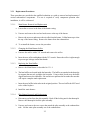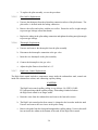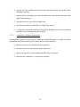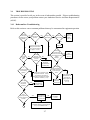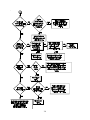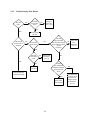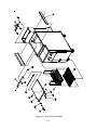
1
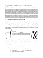
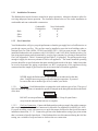
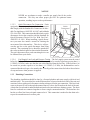
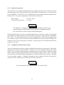
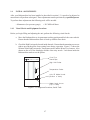
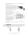
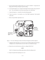
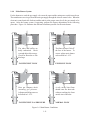
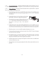
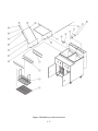
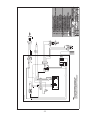
There's Always Something Cooking!
Installation, Operation, Maintenance,
and Service Manual
For The Taco Bell Rethermalizer
Model RTG14
®
Literature Number L20-058
Revision 8
Rev. Date 08/06/96
NOTICES
There are three different types of notices that you should be familiar with, a NOTICE, CAUTION,
and WARNING. A NOTICE is a special note used to call attention to a particularly important point.
CAUTION is used to point out a procedure or operation which may cause equipment damage. The
WARNING notice is the most important of the three because it warns of an operation that may cause
personal injury. Please familiarize yourself with your new Rethermalizer before operating it and
heed the notices throughout this manual. The WARNINGS are listed below and on the following
page for your review prior to operating the unit.
FOR YOUR SAFETY
DO NOT store or use gasoline or other flammable
vapors or liquids in the vicinity of this or any other
appliance.
WARNING: Improper installation, adjustment, alteration, service or maintenance can cause property damage, injury or death. Read the installation, operating
and maintenance thoroughly before installing or servicing this equipment.
TO THE PURCHASER
POST IN A PROMINENT LOCATION INSTRUCTIONS TO
BE FOLLOWED IN THE EVENT THAT AN OPERATOR
SMELLS GAS. OBTAIN THIS INFORMATION FROM YOUR
LOCAL GAS SUPPLIER.
SAFETY
SAFETY
SAFETY
SAFETY
SAFETY
WARNING
This appliance is equipped with a three prong (grounding) plug. This is for
your protection against shock hazard in the event of equipment malfunction.
Always plug the unit directly into a properly grounded three-prong receptacle.
DO NOT cut or remove the grounding (third) prong.
WARNING
DO NOT use an open flame to check for gas leaks! Keep all open flames away
from the Rethermalizer until the installation is complete.
WARNING
A Rethermalizer equipped with casters and a flexible power cord, must be
connected to the gas supply with a Quick-Disconnect device. This quick
disconnect must comply with ANSI Z24.41. To limit the movement of the
unit without depending on the connector or quick disconnect, a restraining
cable must also be installed.
WARNING
There is an open gas flame inside the Rethermalizer. The unit may get hot
enough to set nearby materials on fire. Keep the area around the unit free from
combustibles.
WARNING
Ensure that the Rethermalizer can get enough air to keep the flame burning
correctly. If the flame is starved for air it can give off a dangerous carbon
monoxide gas. Carbon Monoxide is a clear odorless gas that can cause
suffocation.
WARNING
Carbon monoxide can build up if you block the flue. Blocking the flue will
also cause the unit to overheat. DO NOT obstruct the flow of combustion/
ventilation or air opening around the Rethermalizer. Ensure that you meet the
minimum clearances specified in the installation instructions. Adequate
clearance around the unit is necessary for servicing and proper burner
operation.
THIS MANUAL MUST BE RETAINED FOR FUTURE REFERENCE
SAFETY
SAFETY
SAFETY
SAFETY
SAFETY
SAFETY
SAFETY
SAFETY
SAFETY
SAFETY
WARNING
Wait 5 minutes before attempting to relight the pilot. This will allow for any
gas in the unit to dissipate.
WARNING
The power supply must be disconnected before servicing or cleaning the
appliance.
WARNING
DO NOT supply the fryer with a gas that is not indicated on the data plate. If
you need to convert the fryer to another type of fuel, contact your dealer.
THIS MANUAL MUST BE RETAINED FOR FUTURE REFERENCE
SAFETY
SAFETY
SAFETY
SAFETY
SAFETY
Table of Contents
Section
Title
Page
Safety Notice
Table of Contents ........................................................................................................................... i
List of Tables and Figures ............................................................................................................. iii
Chapter 1: General Information and Installation ................................................................. 1-1
1.1
CHECKING YOUR NEW RETHERMALIZER ............................................................ 1-1
1.1.1
Check Your Order ..................................................................................................... 1-1
1.2
ASSEMBLY AND LEVELING ..................................................................................... 1-2
1.2.1
Caster Installation and Adjustment ........................................................................... 1-2
1.3
INSTALLATION ............................................................................................................ 1-2
1.3.1
Installation Clearances ............................................................................................... 1-3
1.3.2
Gas Connection ......................................................................................................... 1-3
1.3.2.1
Fuel Types ........................................................................................................... 1-3
1.3.2.2
Gas Line Connection ........................................................................................... 1-3
1.3.2.3
Quick Disconnect Gas Connection ...................................................................... 1-4
1.3.2.4
Fuel Supply Line Leak and Pressure Testing ...................................................... 1-4
1.3.3
Plumbing Connections ............................................................................................... 1-4
1.3.4
Electrical Connection ................................................................................................ 1-4
1.3.5
Ventilation and Fire Safety Systems ......................................................................... 1-5
1.4
INITIAL ADJUSTMENTS ............................................................................................. 1-7
1.4.1
Visual Checks and Equipment Locations .................................................................. 1-7
1.4.2
Filling the Rethermalizer ........................................................................................... 1-8
1.4.3
Pilot Light System ..................................................................................................... 1-8
1.4.3.1
Pilot Flame Adjustment ....................................................................................... 1-9
1.4.4
Main Burner System ................................................................................................ 1-11
1.4.4.1
Gas Line Requirements ..................................................................................... 1-12
1.4.4.2
Burner Adjustment ............................................................................................ 1-12
1.4.5
Initial Cleaning ........................................................................................................ 1-13
1.4.6
Electronic Control Unit ........................................................................................... 1-14
1.4.7
High Limit Switch ................................................................................................... 1-14
Chapter 2: Operating Instructions ......................................................................................... 2-1
2.1
FILLING THE RETHERMALIZER ............................................................................... 2-1
2.1.1
Manual Operation of The Water Fill System ............................................................ 2-1
2.2
DAILY OPERATING INSTRUCTIONS ....................................................................... 2-2
2.2.1
Start-Up and Use ....................................................................................................... 2-2
2.2.2
Shutdown ................................................................................................................... 2-2
2.3
DAILY CLEANING ....................................................................................................... 2.3
i
Table of Contents (Continued)
Section
Title
Page
Chapter 3: Maintenance, Adjustments, and Service ............................................................. 3-1
3.1
WEEKLY CLEANING ................................................................................................... 3-1
3.2
FLUE AND BAFFLE INSPECTION ............................................................................. 3-2
3.3
SERVICE ....................................................................................................................... 3-2
3.3.1
Replacement Procedures............................................................................................ 3-3
3.3.1.1
Main Burner Removal and Replacement............................................................. 3-3
3.3.1.2
Changing the Main Burner Orifice ...................................................................... 3-3
3.3.1.3
Replacing the Heat Baffles .................................................................................. 3-3
3.3.1.4
Pilot Burner Removal and Replacement ............................................................. 3-3
3.3.1.5
Pilot Orifice Replacement ................................................................................... 3-4
3.3.1.6
Thermopile Replacement ..................................................................................... 3-4
3.3.1.7
High Limit Control Replacement ........................................................................ 3-4
3.3.1.8
Temperature Controller Replacement ................................................................. 3-5
3.3.2
Temperature Controller Calibration .......................................................................... 3-6
3.4
TROUBLESHOOTING .................................................................................................. 3-7
3.4.1
Rethermalizer Troubleshooting ................................................................................. 3-7
3.4.2
Troubleshooting Pilot Burner .................................................................................... 3-9
Chapter 4: Parts ....................................................................................................................... 4-1
Alphabetical Part List .................................................................................................... 4-18
Numerical Part List ........................................................................................................ 4-20
Chapter 5: Schematics.............................................................................................................. 5-1
ii
List of Tables and Figures
Table
Title
Page
1-1
Ventilation and Fire Safety References ........................................................................... 1-6
4-1
4-2
4-3
4-4
4-5
4-6
4-7
4-8
Tank And Cabinet ............................................................................................................ 4-2
Cabinet Joining Kit .......................................................................................................... 4-4
Heating Components ....................................................................................................... 4-6
Front Panel, Assembly ..................................................................................................... 4-8
Tank & Fluid Components ............................................................................................ 4-10
Dual Fryer Including Fluid & Heat Components .......................................................... 4-12
Accessories Assembly ................................................................................................... 4-14
Dual Fryer With Accessories ......................................................................................... 4-16
Figure
Title
Page
1-1
1-2
1-3
1-4
1-5
Component Locations, Inside Tank ................................................................................. 1-7
Pilot assembly, Flame Adjustment .................................................................................. 1-9
Gas Valve Showing Location of the Pressure Regulator and Pilot Adjusters ............... 1-10
Main Burner Conditions ................................................................................................ 1-11
Air Collar ..................................................................................................................... 1-13
4-1
4-2
4-3
4-4
4-5
4-6
4-7
4-8
Tank And Cabinet ............................................................................................................ 4-3
Cabinet Joining Kit .......................................................................................................... 4-5
Heating Components ....................................................................................................... 4-7
Front Panel, Assembly ..................................................................................................... 4-9
Tank & Fluid Components ............................................................................................ 4-11
Dual Fryer Including Fluid & Heat Components .......................................................... 4-13
Accessories Assembly ................................................................................................... 4-15
Dual Fryer With Accessories ......................................................................................... 4-17
iii
iv
Chapter 1: General Information and Installation
The Pitco Frialator Rethermalizer is a revolutionary new reheating unit. By using Pitco Frialator's
tube fired heating system, the Rethermalizer is up to temperature and ready to cook in minutes. Each
of the heating tanks holds approximately 15 gallons of water which is maintained automatically by
the unit. The temperature of each tank is monitored and controlled by its own electronic unit mounted
in the front panel. Each electronic unit is preset at the factory to maintain the temperature of its tank
at 195°F. Quick recovery time and even temperatures are assured by using a 55,000 BTU main burner
system for each tank. The Rethermalizer is very easy to use allowing you to cook and not worry about
the unit. However, it is important that you familiarize yourself with the operation and safety notices
of this manual. This manual contains the installation, operation, and maintenance procedures for the
Taco Bell Rethermalizer. Do not throw away this manual after use, store in a safe place for reference.
1.1
CHECKING YOUR NEW RETHERMALIZER
Every effort has been made to ensure that your Rethermalizer will be delivered to you in perfect
condition. As you unpack the Rethermalizer, inspect the unit for damage. If something is damaged,
DO NOT sign the bill of lading. Contact the shipper immediately, because the shipper is only
responsible for 15 days after delivery. Check the packing list enclosed with your Rethermalizer to
ensure that you have received everything on the list. If you are missing any parts, contact the dealer
from whom the unit was purchased. As you unpack the Rethermalizer be careful to keep its weight
evenly distributed.
Flue Vents
CAUTION
To prevent equipment damage, don't tilt the unit onto
any three of its casters or pull the unit by the flue vents.
Locate your Pitco Frialator warranty and fill in the serial number of the Rethermalizer and the date
received. You will find the serial number on the plate inside the door. Put your warranty in a safe
place for future reference. DO NOT return the warranty sheet to Pitco Frialator. The Rethermalizer
has been assembled for you at the factory and is ready to be installed.
1.1.1
Check Your Order
In the shipping crate with the Rethermalizer you will also find:
(1)
(1)
(1)
Cleaning Brush
(2)
Meat Racks
(1)
Water Hose and Quick Disconnect
1-1
Tube Screens
Pan Support Rack Kit
1.2
ASSEMBLY AND LEVELING
When you receive your Rethermalizer it is completely assembled with the possible exception of the
casters.
1.2.1
Caster Installation and Adjustment
Installing the casters on the Rethermalizer is done with a 7/16" wrench and socket. The casters must
be installed before connecting the unit to the gas supply. The casters provide the necessary height
to meet sanitation requirements and assure adequate air supply to the burner. Attach the casters by
performing the following procedure.
a. Lay the Rethermalizer on its back being careful not to damage the flue by pulling on it.
Protect the outside of the unit with cardboard or a drop cloth when laying it down.
b. Attach each caster with the hex head cap nut supplied with the
Rethermalizer. Each caster requires four 1/4-20 x 5/8" bolt.
c. Mount the bolts from the inside of the unit with the nut on the
outside of the cooker. The nuts have lock washers attached to
them, therefore it is not necessary to use lock washers.
d. When all six casters are mounted, stand the unit up being
careful not to put too much weight on any one caster.
e. Move the Rethermalizer to the desired location and lock the
wheels using the front locking devices on each caster.
1.3
INSTALLATION
Although it is possible for you to install and set up your new Rethermalizer, it is STRONGLY
recommended that you have it done by qualified professionals. The professionals that install your
new Rethermalizer will know the local building codes and ensure that your installation is safe. This
manual provides the installer with valuable information on the installation of your Rethermalizer.
WARNING
DO NOT obstruct the flow of combustion/ventilation or air openings around
the rethermalizer. Adequate clearance around the rethermalizer is necessary
for servicing and proper burner operation. Ensure that you meet the minimum
clearances specified in the installation instructions.
1-2
1.3.1
Installation Clearances
The Rethermalizer needs clearance around it for proper operation. Adequate clearances allow for
servicing and proper burner operation. The clearances shown below are for cooker installation in
combustible and non-combustible construction.
Back
Sides
Floor
1.3.2
Combustible
Construction
6"
6"
4"
Non-Combustible
Construction
0"
0"
4"
Gas Connection
Your Rethermalizer will give you peak performance when the gas supply line is of sufficient size to
provide the correct gas flow. The gas line must be installed to meet the local building codes or
National Fuel Gas Code (NFPA 54-1984) and ANSI Z223.1-1988 (or most current). In Canada,
install the Rethermalizer in accordance with CAN1-B149.1 and CAN1-B149.2 and local codes. Gas
line sizing requirements can be determined by your local gas company by referring to National Fuel
Gas Code, Appendix C, Table C-4 (natural gas) and Table C-16 (propane). The gas line must be large
enough to supply the necessary amount of fuel to all appliances. The burner manifold operating
pressure should be as specified on the data plate attached to the inside of the door. Other factors that
are used to determine the piping requirements are BTU requirements of the appliances being
connected and the length of pipe between the meter (main shut off) and the appliances.
WARNING
NEVER supply the Rethermalizer with a gas that is not indicated on the data
plate. Using the incorrect gas type will cause improper operation. If you need
to convert the unit to another type of fuel, contact your dealer.
1.3.2.1
Fuel Types - Each Rethermalizer is equipped to work with one type of fuel. The type of
fuel with which the appliance is intended to operate is stamped on the data plate attached to the inside
of the door.
WARNING
DO NOT use an open flame to check for gas leaks! Keep all open flames
away from the unit until the leak test is complete.
1.3.2.2
Gas Line Connection - Connect the Rethermalizer to the gas supply line with a connector
that complies with the Standard for Connectors for Movable Gas Appliances (ANSI Z21.69-1987).
If you are installing a unit with casters use a quick disconnect discussed in the Quick Disconnect
installation instruction, 1.3.2.3. Connect the gas line to the Rethermalizer using a pipe joint sealant
that is resistant to liquefied petroleum. If the Rethermalizer was disconnected during the fuel line
testing, use a solution of soap and water to leak test the new connection.
1-3
NOTICE
NEVER use an adaptor to make a smaller gas supply line fit the cooker
connection. This may not allow proper gas flow for optimum burner
operation, resulting in poor cooker performance.
1.3.2.3
Quick Disconnect Gas Connection - Units
equipped with casters must be installed with connectors
that comply with the Standard for Connectors for Movable Gas Appliances, ANSI Z21.69-1987, and Addenda
Z21.69A-1989. This connection should include a quick
disconnect device that complies with the Standard for
Quick Disconnect Devices for Use With Gas Fuel ,
ANSI Z21.41-1989. When installing a quick disconnect you must also install a means for limiting the
movement of the rethermalizer. This device will prevent the gas line or the quick disconnect from being
strained. The restraining device should be attached to
the cooker on the back panel as shown in the illustration.
The quick disconnect, hose, and restraining device can
be obtained from your dealer.
Quick
Disconnect
Strain Relief
1.3.2.4
Fuel Supply Line Leak and Pressure Testing - The fuel supply system must be tested
before the Rethermalizer is used. If the fuel line is going to be tested at a pressure greater than (>)
1/2 PSIG (3.45 kPa), make sure that the unit is disconnected from the fuel line. If the fuel line is to
be tested at a pressure equal to or less than (<) 1/2 PSIG (3.45 kPa), the Rethermalizer can be
connected but the unit's gas valve must be shut. Test all gas line connections for leaks with a solution
of soap and water when pressure is applied.
1.3.3
Plumbing Connections
The plumbing installation should be done by a licensed plumber and must comply with local and
national codes. The water inlet line on the Rethermalizer is located on the back side of the unit and
consists of a hose with a quick disconnect similar to that used for the gas connection. This line feeds
water to the auto fill valves through the manual shut-off valves also located on the back of the unit.
A drain line for each tank is underneath the unit and can be inserted into a drainage system. The drain
lines for each tank are connected together to form a single common drain line. The drain line also
has the overflow line from each tank connected to it. This connection is made after the drain valve
to provide an unobstructed overflow path.
1-4
1.3.4
Electrical Connection
The electrical service used by the Rethermalizer must comply with local codes. If there are no local
codes that apply, refer to the National Electrical Code (NEC) to install the service. In Canada refer
to CSA Standard C22.1 and local codes. Wiring diagrams are provided inside the front panel of the
Rethermalizer. The power requirements for the unit are shown below.
Input Voltage
Current per Rethermalizer
120 VAC, 60Hz
0.5 Amps
WARNING
This appliance is equipped with a three prong (grounding) plug for your
protection against electrical shock hazard in the event of equipment malfunction. DO NOT cut or remove the grounding (third) prong.
The Rethermalizer has two power cords which supplies power to the unit's controls. The unit must
be grounded in accordance with local code; if there is not a local code, comply with NEC ANSI/NFPA
No. 70-1987. It is advised that these power cords be plugged into a wall receptacle supplied from
the ventilation control. This will ensure that the Rethermalizer can not be operated unless the
ventilator is also on to provide proper ventilation. Disconnect power to the Rethermalizer before
cleaning or servicing.
1.3.5
Ventilation and Fire Safety Systems
Your new Rethermalizer must have proper ventilation to function safely and properly. Exhaust gas
temperatures can reach as high as 1200°F. Therefore, it is very important to install a fire safety
system. Your ventilation system should be designed to allow for easy cleaning. Frequent cleaning
of the ventilation system and the Rethermalizer will reduce the chances of fire. Table 1-1 provides
a list of reference documents that provide guidance on ventilation and fire safety systems. This table
is not necessarily complete. Additional information can be obtained from the American Gas
Association, 8501 East Pleasant Valley Road, Cleveland, OH 44131.
WARNING
Never stand on the rethermalizer to service or clean the hood.
1-5
CAUTION
Ensure that your ventilation system does not cause a back draft (down draft)
at the unit's flue opening. Back drafts will not allow the Rethermalizer to
exhaust properly and will cause overheating which may cause permanent
damage. Damage caused by backdrafts will not be covered under equipment
warranty. NEVER allow anything to obstruct the flow of combustibles or
ventilation exiting from the unit's flue. DO NOT put anything on top of the
flue area.
Table 1-1 Ventilation and Fire Safety References
Topic
Underwriters Laboratory
Document
National Fuel Gas Code
Document
Grease Extractor
ANSI/UL 710-1981
ANSI/NFPA 96-1987
Ventilation Hood
ANSI/UL 705-1984
ANSI/NFPA 96-1987
Filter Unit
ANSI/UL 586-1985
ANSI/UL 900-1987
ANSI/NFPA 96-1987
ANSI/UL 154-1983
ANSI/NFPA 12-1989
Dry Chemical
ANSI/UL 299-1984
ANSI/NFPA 17-1985
Water
ANSI/UL 626-1984
ANSI/NFPA 13-1989
Types of Fire Extingushers
and Detection Equipment
Foam
ANSI/NFPA 11-1988
Sprinklers
ANSI/UL 199-1982
ANSI/NFPA 13-1989
ANSI/NFPA 13-1989
Smoke Detectors
ANSI/UL 268-1981
ANSI/FPA 72B-1986
Fire
Detection ANSI/UL 521-1987
ANSI/FPA 72B-1986
Th
t t
Excessive ventilation causes drafts, which will interfere with the proper operation of the pilot and the
burner. Leave at least 18 inches of open space between the Rethermalizer's flue vent opening and
the intake of the exhaust hood.
NOTICE
NEVER connect the blower hood vent directly to the flue openings. The
direct flow of air will cause poor temperature recovery, poor ignition,
inefficient operation of the Rethermalizer, and could extinguish the pilot.
1-6
1.4
INITIAL ADJUSTMENTS
After your Rethermalizer has been installed as described in section 1.3, it needs to be adjusted to
ensure that it will perform as designed. These adjustments must be performed by a qualified person.
To perform these adjustments the following tools will be needed:
• Manometer (low pressure gauge)
1.4.1
• DC Millivolt Meter
Visual Checks and Equipment Locations
Before you begin filling and adjusting the unit, perform the following visual checks:
a. Move the Rethermalizer to its permanent cooking position and lock the caster wheels.
Ensure that the Rethermalizer drain is lined up with the floor drain.
b. Check the High Limit probe located inside the tank. Ensure that the mounting screws are
tight to prevent the probe from coming loose during operation. Figure 1-1 shows the
location of the High Limit probe, Temperature probe, and the Water Level sensors. Also
shown are the over flow stand pipe and the water entry nozzle. Look down inside the
Rethermalizer tanks to see the probes.
Over Flow
Stand Pipe
High Limit Probe
Temperature Probe
Auto Fill Water Nozzle
(Bottom of tank)
Water Level Sensors
(Top of tank)
Figure 1-1 Component Locations, Inside Tank
1-7
1.4.2 Filling the Rethermalizer
The Rethermalizer is equipped with an automatic water level
maintaining system. To fill the unit with water place the ON/
OFF switch in the ON position. This causes the solenoid valve
to open and supply water to the unit through the fill nozzle in
the bottom of the tank. The tank will continue to fill until the
water level reaches the level sensors. When both water level
sensors are covered the solenoid valve will close stopping the
flow of water. During normal operation the automatic fill system will maintain the water level at the
proper height.
OFF
NOTE
During normal operation the automatic water fill system will continue to
control the water level in the Rethermalizer tank. If the water control system
turns on while the main burners are lit the main burners will turn off. This is
normal and will not affect the operation of the Rethermalizer. When the tank
refills to the high level probe the solenoid will close and the main burners will
relight.
1.4.3
Pilot Light System
The Rethermalizer uses a manual pilot light system to light the main burners. The pilot light receives
its gas supply through the electrically controlled gas valve. To light the pilot perform the procedure
below.
a. Each side of the unit has its own gas supply valve. This allows one side to be serviced
while the other is operating. These gas valves should normally be open.
b. Turn the gas valve knob to the PILOT position and push in on the knob.
Hold the knob in for approximately one minute to purge the air out of
the line. Hold a flame to the pilot light until the pilot ignites. This may
take a little while the first time you light the Rethermalizer because of
air in the lines. Once lit, hold the knob in for approximately 60 seconds
and then release.
WARNING
Wait 5 minutes before attempting to relight the pilot. This will allow
for any gas in the unit to dissipate.
c. Turn the gas knob counterclockwise to the ON position.
1-8
d. If the pilot goes out repeat step c. If after three tries the pilot will not remain lit, contact
a qualified service technician.
e. Place the ON/OFF switch in the ON position. The
electronic control unit will come on and display the
temperature of the water. There will also be a red
light lit between the left and middle digits of the
display. This light indicates that the electronic
control unit is calling for heat. If the water level is
below the low level sensor the water solenoid valve
will open and fill the tank.
f. When the water in the tank is at the
correct level the main burner will
light and be controlled by the electronic control unit. The pilot burner
will remain lit regardless of the
switch position.
g. The burners will remain lit until the
temperature reaches 195°F where
they will turn off. While the burners
are off the red light in the electronic
display will be off. The burners will
maintain the water temperature between 194°F and 196°F.
OFF
HEAT DEMAND LIGHT
OUTPUT
˚F
ADJUST
SET
CONTROL PRODUCTS, INC. USA
h. When the ON/OFF switch is in the ON position the water level will be maintained by the
water fill system.
Pilot Flame Adjustment - The pilot flame should be adjusted to produce between 300 and
1.4.3.1
500 millivolts output from the thermopile. Figure 1-2 shows the pilot assembly with examples of
the incorrect and correct pilot size. Example A illustrates a pilot size that is too small to produce
sufficient millivolt output. Example B is the correct size for proper millivolt output.
A
B
Figure 1-2 Pilot Assembly, Flame Adjustment
1-9
a. This test requires the DC millivolt meter set to a scale of 0-1000mV. Using leads with
sharp probes will help in taking the required reading.
b. Locate the thermopile wires coming from the High Limit box going to the gas shut off
valve. The wire insulation size decreases near the gas valve connections.
c. Connect the negative (-) test probe to the pilot tubing (ground).
d. Connect the positive (+) test probe to one of the High Temperature Limit terminal
connections.
e. Remove the pilot flame adjustment cover.
P
OFF
ON
ILOT
R
OB
E
W
VENT
PILOT
RTS H A
TH TR
Regulator
adjustment
screw can be
found under
this cap screw
Pilot adjustment
screw can be
found under this
screw.
Figure 1-3 Gas Valve Showing Location of the Pressure Regulator and Pilot Adjusters.
f. Turning the flame adjusting screw clockwise lowers the flame and the millivolt output.
Turning the screw counterclockwise increases flame size and millivolt output.
g. Rotate the screw in the direction to achieve a reading of 400±50 mV.
NOTE
Allow 3 to 5 minutes between flame adjustments to allow the reading to settle.
h. Replace the pilot flame adjusting screw cover.
1-10
1.4.4
Main Burner System
For the burners to work the gas supply valve must be open and the main power switch must be on.
The main burners receive gas from the main gas supply through the electric control valve. When the
electronic control unit calls for heat (and the tank is at the proper water level), the gas control valve
opens. After the burner system is operating, perform the burner adjustments in the following
procedure. Figure 1-4 illustrates the different conditions possible for the main burner.
The tubes and baffles are
badly carbonized. Check
vent and adjust if necessary.
Check for heat tube or flue
blockage.
The flame seems to "lift off"
the face of the burner. To
correct adjust main burner
as described in 1.4.3.2.
INSUFFICIENT FLOW
EXCESSIVE FLOW
Have gas company check
incoming gas pressure.
Adjust manifold pressure as
described in 1.4.3.2.
A soft, steady blue flame
should enter the heat tube
without touching the front
outside rim of the tube.
INSUFFICIENT GAS PRESSURE
NORMAL FLOW
Figure 1-4 Main Burner Conditions
1-11
1.4.4.1
Gas Line Requirements - A properly installed gas supply system will deliver 7.0 ±2.0"
w.c. natural gas (12.0 ±2.0" w.c. LP) to all appliances connected to the line, operating at full demand.
Burner Adjustment - The burners must be adjusted to deliver optimum flame. Adjust the
1.4.4.2
burner flame using the following procedure.
a. Ensure that the gas control valve is in the PILOT position. Remove the manifold pressure
tap plug and connect an accurate pressure gauge (range of 0-16" w.c. in 0.1" increments)
or manometer.
b. Light the pilot burner for the unit being tested and place
the ON/OFF switch in On to light the main burners.
c. The installed pressure gauge reading should be the same,
±0.1", as that marked on the data plate inside the door. If
the pressure is correct go to step e, if not, adjust the
pressure.
OFF
d. To adjust the pressure, remove the regulator adjustment screw cover (see Figure 1-3). Use
a flat tip screwdriver to adjust the screw until the proper pressure is reached. Turning the
screw clockwise will increase the pressure, counterclockwise will decrease the pressure.
e. When the pressure is correct, install the regulator adjustment screw cover.
f. To remove the pressure gauge, turn the gas control valve to PILOT. Remove the gauge
and install the pressure tap plug.
g. Now that the pressure is set for proper operation, set the main burner flame. Unlock the
air collars by loosening the set screw for the collars. Turn the gas control valve to ON
and place the ON/OFF switch in ON to light the main burners.
h. Adjust the shape and size by raising or lowering the air collars to achieve a soft blue flame
with well defined inner cones.
i. When the flames have been properly adjusted, lock the collars in place with the set screw
provided.
1-12
Figure 1-5 Air Collar
1.4.5
Initial Cleaning
When the Rethermalizer is shipped, many of its parts are covered with a thin coat of oil for protection.
Before the unit is ready for use it must be cleaned to remove the oil coating and any foreign matter
that may have accumulated during storage and shipment. Perform the cleaning as described below.
a. Fill the tank with water and add a mild detergent to the tank being cleaned.
b. Turn the Rethermalizer on and allow it to reach normal operating temperature. Allow the
unit to soak for a short time to remove the oil coating. Use the supplied cleaning brush
to clean the tank.
c. When the cleaning is complete, turn off switch to OFF and drain the water.
d. When the tank has cooled, rinse it thoroughly with cool water. Continue to rinse the tank
until the cleaner has been rinsed from the tank.
e. Now that the tank is clean, you are ready to fill and operate the Rethermalizer.
1-13
1.4.6
These controls are jumpered out.
Electronic Control Unit
OUTPUT
The electronic control unit is preset at the factory to maintain
195°F. If the control unit should become erratic contact
service.
˚F
ADJUST
SET
CONTROL PRODUCTS, INC. USA
1.4.7
High Limit Switch
The High Limit switch will shut down the unit if the temperature reaches 425°F.
1-14
Chapter 2: Operating Instructions
This chapter describes how to operate your Rethermalizer to obtain the best performance. Included
in this chapter are filling, operating, and cleaning instructions.
2.1
FILLING THE RETHERMALIZER
The Rethermalizer is equipped with an automatic water level maintaining system. To fill the unit with
water place the ON/OFF switch in ON. This causes the solenoid valve to open and supply water to
the unit through the fill nozzle in the bottom of the tank. The tank will continue to fill until the water
level reaches the level sensors. When both water level sensors are covered the solenoid valve will
close stopping the flow of water. During normal operation the automatic fill system will maintain
the water level at the proper height.
NOTE
During normal operation the automatic water fill system will continue to
control the water level in the Rethermalizer tank. If the water control system
turns on while the main burners are lit the main burners will turn off. This is
normal and will not affect the operation of the Rethermalizer. When the tank
refills to the high level probe the solenoid will close and the main burners will
relight.
2.1.1
Manual Operation of The Water Fill System
CAUTION
When the water solenoid is by-passed the automatic water fill system WILL
NOT maintain the water level. The water level control system should remain
in automatic during normal operation.
Although the water fill system is completely automatic, the solenoid valve can be by-passed
manually to fill the tank. To by-pass the water solenoid valve open the valve in the by-pass pipe. This
should only be done if the solenoid valve fails and the Rethermalizer needs to be operated. When
finished filling the Rethermalizer ensure that the solenoid manual by-pass valve is returned to its
normal position.
2-1
2.2
DAILY OPERATING INSTRUCTIONS
This section provides you with the information necessary to perform routine operations. To ensure
that the product always comes out the very best, follow the preparation instructions for the food you
are cooking.
2.2.1
Start-Up and Use
a. Light the pilot light as described in section 1.4.3..
b. Place the ON/OFF switch in ON. If the tank is not
at the proper operating height the solenoid valve
will open and fill the tank.
c. When the water reaches the proper operating level.
The main burners will light and the electronic unit
will take over and control the water temperature.
When the electronic control unit is calling for heat
the red LED will also be on.
d. The main burners will remain on until 195°F is
reached at which time they will turn off. The
Rethermalizer is now up to temperature and ready
to accept the food to be heated. Place the food to
be heated in the rack and lower into the water.
OFF
HEAT DEMAND LIGHT
OUTPUT
˚F
ADJUST
SET
e. The electronic unit will maintain the water temperature at approximately 195°F and the water fill
system will keep the water at the proper level.
2.2.2
CONTROL PRODUCTS, INC. USA
Shutdown
There are two shutdown modes for the Rethermalizer, STANDBY and COMPLETE. The standby
mode removes the ability for the unit's main burners to cycle. Complete shutdown turns off the gas
supply to the unit.
STANDBY
Place the ON/OFF switch in the OFF position. Depress and turn the
gas valve clockwise to the PILOT position. The Rethermalizer is
now in Standby and can remain this way for only brief periods of
time. NEVER leave the unit in standby overnight.
COMPLETE To completely shut down the Rethermalizer, turn the gas valve
clockwise to the OFF position.
2-2
2.3
DAILY CLEANING
WARNING
The power supply must be disconnected before servicing or cleaning the appliance
Your Rethermalizer should be cleaned every day to maintain peak performance and appearance.
Perform the procedures below every day.
a. Use warm water with a mild detergent to clean exterior surfaces. Wipe down the unit
using a clean soft cloth to clean up water spillage.
b. Use a non-abrasive scouring powder or pad to clean stains if necessary.
c. Perform the cleaning of the Rethermalizer described in section 3.1 at least weekly.
2-3
2-4
Chapter 3: Maintenance, Adjustments, and Service
This chapter provides you with the information and procedures necessary to perform Rethermalizer
maintenance, adjustments, and service. If after performing maintenance on your Rethermalizer it
does not operate properly, contact your authorized service center.
WARNING
The power supply must be disconnected before servicing or cleaning the
appliance.
NOTICE
The unit has casters and therefore it has a quick disconnect gas connection and
a restraining device. Care should be exercised when moving the unit out to
be serviced. When you are moving the unit back into place ensure that you
connect the restraining device before you move the unit back into place. You
should also be careful not to kink the gas or water hose.
3.1
WEEKLY CLEANING
The continuous filling and evaporation of water from the Rethermalizer will cause deposit build up
around the tank. At least once a week the unit should be thoroughly cleaned to remove these deposits
and generally clean the unit. Perform the cleaning as described below.
a. Fill the tank with water and add a mild detergent to the tank being cleaned.
b. Turn the Rethermalizer on and allow it to reach
normal operating temperature. Allow the unit to soak
for a short time to remove residue. Use the cleaning
brush to remove deposits from the tank cooking
surface. You can use a non-abrasive scouring powder
or pad to clean stains if necessary. When cleaning
around the High Limit bulb be careful not to damage the bulb or its capillary tube.
c. When the cleaning is complete, turn off the unit and shut the gas valve and drain the water.
d. When the tank has cooled, rinse it thoroughly with cool water. Continue to rinse the tank
until the cleaner has been rinsed from the tank.
e. Now that the tank is clean, you are ready to fill and operate the Rethermalizer.
f. If during cleaning, or any other reason, the restraining device is disconnected, it must be
reconnected and the Rethermalizer returned to its original cooking position before
operated.
3-1
3.2
FLUE AND BAFFLE INSPECTION
It is recommended that once every six months with the cooker cooled down you examine the flue area
and the burner tube baffles. Check for corrosion or blockage of the flue and erosion of the baffles.
The burners should be removed to thoroughly inspect the baffles. If necessary clean the heat tube
area and replace the baffles if they are eroded or distorted. Ensure that the cooker is shutdown and
do not turn it on during the examination. Examination of the flue area during cooking may cause
bodily injury.
3.3
SERVICE
If servicing is required, electrical components can be accessed through the front panel. To gain access
to the front panel electrical components, remove the four screws on the front panel. Remove the front
panel and set aside with the four screws for installation after servicing is complete. An electrical
diagram is supplied inside the front panel for use by an authorized service person. There is also an
electrical diagram in the back of this manual. The electrical diagram can be used to verify the proper
operation of the electrical systems. After servicing is complete, the diagram should be replaced for
future reference and the front panel installed.
WARNING
To prevent burns, always ensure that the unit is completely SHUT DOWN and
COOLED down before working on the Rethermalizer. Do not break any gas
connections while the unit is connected to a gas supply line.
WARNING
The power supply must be disconnected before servicing or cleaning the
appliance.
NOTICE
The unit has casters and therefore has a quick disconnect gas connection and
a restraining device. Care should be exercised when moving the unit out to
be serviced. When you are moving the unit back into place ensure that you
connect the restraining device before you move the unit back into place. You
should also be careful not to kink the gas or water hose.
3-2
3.3.1
Replacement Procedures
These procedures are provided to the qualified technician as a guide to removal and replacement of
various rethermalizer components. If a test is required to verify component operation after
installation, it will be referenced.
3.3.1.1
Main Burner Removal and Replacement
a. Loosen the set screw in the base of the burner casing.
b. Unscrew and remove the two hex head screws at the top of the burner.
c. Remove the set screw and remove the air collar from the burner. Lift the burner up to clear
the top of the burner fitting. Remove the burner from the rethermalizer.
d. To re-install the burner, reverse the procedure.
3.3.1.2
Changing the Main Burner Orifice
a. Unscrew the orifice with a 3/8" wrench and remove the orifice.
b. Insert the new orifice and tighten with the 3/8" wrench. Ensure the orifice is tight enough
to prevent gas leakage around the threads.
3.3.1.3
Replacing the Heat Baffles
a. Remove the Main Burner as described in 3.3.1.1.
b. The heat baffles are located inside the heat tubes. The baffles are attached to the heat tube
by supports that are tack welded to the heat tube. Using a chisel, break away the baffle
support and remove the old baffles. Be careful not to puncture the heat tubes because this
will require complete tank replacement.
c. Insert the new baffles in the tubes in the original position. The new baffles do NOT need
to be welded in place.
d. Install the main burners.
3.3.1.4
Pilot Burner Removal and Replacement
a. Disconnect gas line from the pilot assembly. Back off the locking nut for the thermopile.
Remove the thermopile from the pilot assembly.
b. Unscrew and remove the two screws that attach the pilot assembly to the rethermalizer
tank. Lift the entire pilot assembly out of the rethermalizer.
3-3
c. To replace the pilot assembly, reverse the procedure.
3.3.1.5
Pilot Orifice Replacement
a. Unscrew the tubing nut from the pilot tubing connection at base of the pilot burner. The
pilot orifice is located inside the tubing connection.
b. Remove the orifice and replace with the new orifice. Ensure the orifice is tight enough
to prevent gas leakage around the threads.
c. Replace the tubing in the pilot tubing connection and tighten the tubing nut tight enough
to prevent gas leakage.
3.3.1.6
Thermopile Replacement
a. Unscrew and remove the thermopile from the pilot assembly.
b. Disconnect the thermopile connection at the gas valve.
c. Insert the new thermopile in the pilot assembly.
d. Connect the thermopile to the gas valve.
e. Adjust the pilot flame as described in 1.4.3.
3.3.1.7
High Limit Control Replacement
The High Limit control includes a temperature sensor inside the rethermalizer tank, control unit
inside the rethermalizer cabinet, and connecting capillary tubing.
CAUTION
The High Limit control capillary tubing is very delicate. Be VERY CAREFUL when working with the capillary tubing. If the tubing is kinked or broken
the High Limit control is no longer usable.
a. Drain the water from the rethermalizer and remove the heat tube screens.
b. The High Limit control probe (heat sensor) is clamped to the heat tube inside the tank.
Unscrew and remove the two screws in the probe clamp.
c. Remove the probe from the clamp and straighten the capillary tubing. Unscrew the small
hex nut inside the cabinet at the bottom of the tank for the High Limit control.
3-4
d. Unscrew the large connector nut from the tank and pull the probe and capillary tubes
through the opening.
e. Remove the two mounting screws from the High Limit control bracket and remove the
High Limit control unit.
f. Disconnect the two wires from the High Limit.
g. Reverse the procedure to install the new High Limit control.
h. Use pipe joint compound on the large fitting before installing to prevent water leakage.
DO NOT use joint compound on the small nut.
3.3.1.8
Temperature Controller Replacement
The temperature controller is press fit into the front panel of the Rethermalizer. To replace or perform
maintenance in the unit you must gain access to the back of the controller.
a. Remove the four screws that hold the front panel on.
b. Disconnect the wires from the back of the control unit.
c. Depress the side tabs on the controller and slide it out of the panel.
d. Install the new controller by reversing the procedure.
3-5
3.3.2
Temperature Controller Calibration
The temperature controller does not need routine calibration. It will maintain its factory set
calibration during normal operations. In some instances if the controller receives a static charge it
can become erratic. Static charge can scramble the controllers program. If this should happen first
try to correct the problem by draining the tank and allowing to refill with cool water. This will drop
the temperature of the water well below the normal operating temperature and may reset the
controller program. If this does not reset the controller perform the calibration procedure below.
a. Gain access to the rear of the controller by removing the front panel of the rethermalizer.
b. Install a jumper between the +5 and -3 volt terminals. This enables the controls on the
front of the controller.
NOTE
If during the setting procedure you stop for longer than 15 seconds the
controller will revert to the temperature display mode WITHOUT changing
its settings.
c. Adjust the differential temperature limit by pressing the °F switch. The display will show
dF1. Press °F again to display the differential setting. For proper operation this number
must be a positive valve. Use the up or down Adjust keys to set the differential number.
d. Press the °F key until the display goes blank. This completes the differential adjustment.
e. To set the setpoint of the controller press the SET key. The display will show SP 1. Press
the SET key again to display the current setting.
f. If the value showing is incorrect use the up and down adjust keys to change the setting.
g. Once the value is correct press the SET key again until the display goes blank. This
completes the set point programming.
3-6
3.4
TROUBLESHOOTING
This section is provided to aid you in the event of rethermalizer trouble. If these troubleshooting
procedures do not correct your problem contact your Authorized Service And Parts Representative
(ASAP).
3.4.1
Rethermalizer Troubleshooting
Refer to this section to correct common problems that may be encountered in equipment operation.
Does pilot
remain lit after
Unitrol Knob is
released?
NO
Is all the air
purged from the
gas line?
YES
Is High Limit
Switch open?
YES
Will Limit
switch reset?
Replace
High Limit
Switch.
(3.3.1.7)
NO
YES
NO
YES
Do main
burners
ignite?
Is Unitrol
Knob fully
counterclockwise
in the ON
position?
NO
YES
YES
Is
temperature control
unit functioning
properly?
NO
With the
High Limit Switch
shut check the continuity
of the switch and wires.
Is there
continuity?
NO
Turn Unitrol knob to
the extreme
counterclockwise
position (ON).
NO
Check wiring connections to the
temperature controller. If wiring
connections are good and the
temperature controller is not working,
replace the controller. (3.3.1.8)
YES
Does pilot
go out when
temperature
increases?
Reset &
Light Pilot
Purge air from gas line by
placing the Unitrol Valve
knob in pilot and holding in
for approx. 1 minute.
YES
Is voltage
from thermopile
>200MV and present
at the Unitrol gas
valve?
YES
NO
Does
fryer temperature
recover slower than
it should?
YES
Check the heat
tube baffles. Are
they burned out?
YES
NO
NO
A
Refer to initial fryer installation instructions
for ventaiation blower (1.3.5) and main gas
line (1.3.2) installation checks.
3-7
Replace High
Limit
switch/wires
(3.3.1.7)
YES
Replace the
Unitrol valve
electromagnet.
Refer to pilot light
trouble shooting
procedures. (3.4.2)
NO
Replace the heat
tube baffles.
(3.3.1.3)
NO
If pilot adjustment
procedures do not
correct the low
voltage, replace the
thermopile.
(3.3.1.6)
3-8
3.4.2
Troubleshooting Pilot Burner
Will pilot
Is the gas
NO
light?
supply valve
open?
Open gas
NO
valve, light
pilot. (1.4.3)
YES
YES
Does pilot stay
lit when knob is
released?
Purge air from
gas line.
With the
High Limit Switch
NO
NO
Is High Limit
Switch open?
shut check the continuity
Replace High
NO
of the switch and wires.
Is there
Limit
switch/wires
(3.3.1.7)
continuity?
YES
Will High
Limit switch
reset?
NO
Replace High
YES
Limit Switch.
(3.3.1.8)
YES
YES
Is voltage
from thermopile
Reset &
NO
>200MV and present
at the Unitrol gas
Light Pilot
valve?
Pilot light system is
functioning properly.
If pilot adjustment
YES
Replace the
Unitrol valve
electromagnet.
3-9
procedures do not
correct the low
voltage, replace
the thermopile.
(3.3.1.6)
3-10
Chapter 4: Parts
This chapter contains listings of the components used in the Taco Bell Rethermalizer. The
illustrations in this chapter are provided to show relative location of component within the fryer. With
each illustration ther is a table of components listed by illustration number.
At the end of this chapter is an alphabetical and numerical listing of most of the common parts in the
fryer.
4-1
Table 4-1 Tank and Cabinet
Item
#
QTY/
Unit
Part
Number
1
1
2
3
4
5
6
7
8
9
10
11
12
13
14
15
16
17
18
19
20
1
1
1
1
1
1
1
2
2
1
1
1
1
1
1
4
2
2
4
16
16
B3310502-C
B3310502-C
B1811501
A1619202
B2301109
B7230302
B7230202
P6071483
PP10025
PP11006
P6071300
A1819602
B3609901
A1822101
A4103602
P0075300
PP10728
PP10652
A3901101
P0020600
P0093300
Description
Tank
Tank
Cabinet, Painted
Back Strip
Door
Hinge, Bottom Right Hand Door
Hinge, Top Right Hand Door
Plug, Hole
Screw
Handle
Magnet
Bracket, Door Magnet
Edge, Marine
Cabinet Spacer, Tank Holder
Splash Back
Screw, 3 #10 x 5/8" Self Drill
Caster With Brake
Caster Without Brake
Caster Mounting Plate
Bolt 1/4-20
Nut 1/4-20
4-2
Figure 4-1 Tank and Cabinet
4-3
Table 4-2 Cabinet Joining Kit
Item
#
QTY/
Unit
Part
Number
1
2
3
4
5
6
7
8
9
10
11
1
1
6
3
3
24
2
2
10
24
8
A1821901
A1821801
A1222501
PP10652
PP10728
P0093300
A1819602
P6071300
P0075200
P0020600
P0075300
Description
Channel Support, front
Rear Cabinet Strip
Mounting Plate, Caster
Caster without Brake
Caster with Brake
Nut, 1/4-20
Bracket, Door Magnet
Magnet
Screw, 2 #8 x 1/2" Self Drill
Bolt, 1/4-20
Screw, 3 #10 x 5/8" Self Drill
Revised 5/28/93
4-4
Figure 4-2 Cabinet Joining Kit
4-5
Table 4-3 Heating Components
Item QTY/
#
Unit
1
2
3
4
5
6
7
8
9
10
11
12
13
14
15
16
17
18
19
20
21
22
23
24
25
26
27
28
29
1
1
2
2
1
2
1
1
1
1
1
1
1
1
1
2
2
2
4
1
2
1
2
2
1
1
2
2
1
1
1
Part
Number
P6071767
P6071450
PP10665
PP10665
A3306402
P0092300
PP10271
A1815501
A8000801
A8013101
B7510102
B8009501
A8000801
A4012801
P0063500
A8001001
PP10025
P6071050
PP10195
A1401002
PP10698
A3701002
P6071341
P6071353
P5045638
P5045639
A8001101
P6071267
P5045660
B6779850
P5047541
Description
Gas Shut-Off Valve
Pilot Assembly, Nat
Screw 10-24 x 3/8" SS
Screw 10-24 x 3/8" SS
Pilot Bracket
Nut, Keep 10-24
High-Limit
Bracket, High-Limit
Bracket, Manifold Mounting RH
Bracket, Thermostat & Unitrol Extension
Extension, Gas Valve Knob
Manifold, Burner
Bracket, Manifold Mounting LH
Clamp, Unitrol Bracket
Screw, Square Head 6-32
Air Collar
Screw, Air Collar Set
Burner
Bolt, Burner Mounting, 1/4-20
Clamp, Bulb and Probe
Screw, 10-24 Round Head SS
Heat Shield, Burner
Orifice, NAT
Orifice, LP
Gas Valve 24V Nat
Gas Valve 24V LP
Fittings, Burner
Knob, Gas Valve
Bracket
Unitrol Limit Wires
Thermopile
4-6
Table 4-3 Heating Components
4-7
Table 4-4 Front Panel, Assembly
Item
#
Qty/
Unit
Part
Number
1
2
3
4
5
6
7
8
9
10
11
12
13
14
15
16
17
18
19
20
21
22
23
24
1
2
1
1
4
1
1
1
2
1
1
1
1
8
1
1
2
1
4
9
1
1
1
1
B3609601
P0075300
A3635002
PP10939
PP10195
PP10654
A6054501
PP10122
P5045794
B6718701
PP10439
PP10146
PP10210
PP10749
PP10702
P5046691
P6071071
P6071223
PP10749
P0091400
A2948301
P5045240
B6714301
B6714101
Description
Front Panel Weldment
Screw 3 10 x 5/8" Self Drill
Bezel Front Panel
Thermostat With 24V Display
Screw, Button Head Hex
Switch, Rocker SPST
Label, Switch
Fuse, 1 Amp Slow Blow, Glass
Fuse Holder
Probe, Temperature Sensing
Cable, Power With Plug
Strain Relief 90°
Transformer Multi to 24 VAC
Screw 6-32 x 5/8
Control, Liquid Level
Relay 120 VAC SPST
Wire Clamp
Grommet
Screw 6-32 x 5/8" SS
Nutsert 6-32
Entrance Box
Clamp, Romex
Harness, Control Cable
Harness, Front Panel
Revised 5/28/93
4-8
Figure 4-4 Front Panel, Assembly
4-9
Table 4-5 Tank & Fluid Components
Item
#
Qty/
Unit
Part
Number
1
2
3
4
5
6
7
8
9
10
11
12
13
14
15
16
17
18
19
20
21
22
23
2
2
1
2
2
2
1
1
2
2
1
1
2
4
2
2
2
2
2
2
2
2
6
B4509301
B4509402
A5053702
A5053602
A3317802
P0142000
A3318902
A3318702
A3319003
P0112000
A3318904
A3319002
P6071361
PP10669
PP10673
PP10670
P0048980
P0142000
PP10729
PP10668
A3317902
PP10668
PP10698
Description
Tube Screen
Taco Rack
Channel Strip
Pan Holder end
Support Hinge Rod
Nut, Acorn, 10-24 SS
Catch, Hinge LH
Hinge Rod
Handle, Catch RH
Screw, 10-24 x 1/2" SS
Catch, Hinge RH
Handle, Catch LH
Handle
Nut, 1/4-20 SS
Washer, Split Lock 1/4" SS
Bolt 1/4-20 x 1" SS
Screw, 10-32 with 1" Shoulder
Nut, Acorn 10-24 SS
Screw, 1/4-20 x 3/8" SS
Nut, Acorn 1/4-20
Cover
Nut, Acorn 1/4-20
Screw, 10-24 x 5/8" SS
4-10
Figure 4-5 Tank & Fluid Components
4-11
Table 4-6 Dual Fryer Including Fluid & Heat Components
Item
#
Qty/
Unit
Part
Number
1
2
3
4
5
6
7
8
Not Shown
2
1
1
1
1
2
1
2
1
PP10676
PP10726
PP10657
PP10659
B8010001
P6071767
P7036013
P7037750
PP10874
Description
Valve, Water Inlet
Valve, Check
Bushing, 1/4" x 1/2" Brass
Tee, 3/8" Brass
Drain Line Assembly
Valve, Gas Supply Shut Off
Bushing, 1/2" x 3/4"
Elbow, 90° x 1/2" Street
Hose, Water Fill with Quick Disconnect
Revised 07/06/93
4-12
Figure 4-6 Dual Fryer Including Fluid & Heat Components
4-13
Table 4-7 Accessories Assembly
Item
#
Qty/
Unit
Part
Number
1
2
3
4
5
6
7
8
9
10
11
12
13
14
15
16
17
18
1
1
1
2
1
1
1
1
1
1
1
3
2
2
2
1
1
1
B3310901
B4509301
B4509402
A5053602
A3318704
A3317802
A3318904
A3319002
P6071261
PP10670
P0048980
PP10698
PP10668
PP10669
PP10673
PP10729
P0112000
P0142000
Description
Cover, Tank
Tube Screen
Taco Rack
Pan Holder End
Hinge Rod
Support, Hinge Rod
Catch Hinge
Handle, Catch
Handle
Bolt, 1/4-20 x 1" SS
Screw, 10-32 with 1" Shoulder
Screw, 10-24 x 5/8" SS
Nut, Acorn
Nut, 1/4-20 SS
Washer, Split Lock 1/4" SS
Bolt, 1/4-20 x 3/8" SS
Screw, 10-24 x 1/2" SS
Nut, Acorn 10-24 SS
Revised 5/28/93
4-14
Figure 4-7 Accessories Assembly
4-15
Table 4-8 Dual Fryer with Accessories
Item
#
Qty/
Unit
Part
Number
1
2
3
4
5
6
7
8
9
10
11
12
13
14
15
16
17
18
19
20
21
22
23
2
2
1
2
2
2
1
1
2
2
1
1
2
4
2
2
2
2
2
2
2
2
6
B4509301
B4509402
A5053702
A5053602
A3317802
PP10668
A3318902
A3318702
A3319003
P0112000
A3318904
A3319002
P6071261
PP10669
PP10673
PP10670
P0048980
P0142000
PP10729
PP10668
A3317902
PP10668
PP10698
Description
Tube Screen
Taco Rack
Channel Strip
Pan Holder End
Support, Hinge Rod
Nut, Acorn 10-24 SS
Catch, Hinge LH
Hinge Rod
Handle, Catch RH
Screw, 10-24 x 1/2" SS
Catch, Hinge RH
Handle, Catch LH
Handle
Nut, 1/4-20 SS
Washer, Split Lock 1/4" SS
Bolt, 1/4-20 x 1" SS
Screw, 10-32 with 1" Shoulder
Nut, Acorn 10-24 SS
Screw, 1/4-20 x 3/8"SS
Nut, Acorn 1/4-20
Cover
Nut, Acorn 1/4-20
Screw, 10-24 x 5/8"SS
Revised 5/28/93
4-16
Figure 4-8 Dual Fryer with Accessories
4-17
ALPHABETICAL PART LIST
Part Description
Part Number
AIR COLLAR ............................................................................................. A8001001
BAFFLE, TANK ......................................................................................... B1000701
BRUSH, NYLON, STRAIGHT .................................................................. PP10730
BOLT, BURNER ........................................................................................ P0115000
BURNER .................................................................................................... P6071050
BURNER PILOT 6CH-14-6, LP ................................................................ P6071449
BURNER PILOT 6CH-14-6, NAT ............................................................. P6071450
CASTER ASSY, ADJUSTABLE W/OUT LOCK, 4" ............................... PP10808
CASTER ASSY, ADJUSTABLE W/LOCK, 4" ........................................ PP10809
CATCH MAGNET STANDARD .............................................................. P6071300
CONNECTOR, PLUG, 2 - SOCKET MOLEX .......................................... P5045140
CONNECTOR, MOLEX PLUG - 4 PIN MALE........................................ PP10202
CONNECTOR. MOLEX JACK - 4 PIN MALE ........................................ PP10203
CONNECTOR, PLUG - 9 PIN MOLEX .................................................... P5045860
CONNECTOR, PLUG - 3 PIN MOLEX .................................................... PP10090
CONNECTOR, PLUG - 2 PIN MOLEX .................................................... P5045829
CONNECTOR, PIN 24-14 AWG MOLEX ................................................ PP10173
CONNECTOR, SOCKET 24-14 AWG MOLEX....................................... PP10172
CONNECTOR, SOCKET 24-14 AWG MOLEX ....................................... P5045862
CONNECTOR, JACK - 3 SOCKET MOLEX ........................................... PP10089
CONNECTOR, JACK - 9 SKT MOLEX ................................................... P5045838
CONNECTOR, JACK - 2 SOCKET MOLEX ........................................... P5045839
CONTROLLER, LIQUID LEVEL - SOLID STATE ................................ PP10797
CORD, PLUG-RETRACTILE 16-3 SJO ................................................... PP10439
DRAIN VALVE, 1-1/4" ............................................................................. PP10565
FUSE, 2 AMP SLOW BLOW, GLASS ..................................................... P5045717
FUSE, 1 AMP SLOW BLOW, GLASS ..................................................... PP10122
HANDLE, DOOR ....................................................................................... P6071516
HEAT DEFLECTOR .................................................................................. A3701002
HIGH LIMIT SWITCH .............................................................................. PP10271
HOSE, WATER FILL WITH QUICK DISCONNECT ............................. PP10874
ORIFICE, MAIN BURNER ....................................................................... P6071341
PROBE, TEMPERATURE- RTG .............................................................. B6718701
RELAY, 24 VDC SPDT WITH MOUNTING TABS ................................ P5046691
STRAIN RELIEF, CONNECTOR ............................................................. PP10146
SWITCH, ROCKER, SPST, 15A ............................................................... PP10654
THERMOPILE ........................................................................................... P5047541
THERMOSTAT, SOLID STATE - 24V WITH DISPLAY ....................... PP10703
TRANSFORMER, 12012081240 TO 24V 40 VA ..................................... PP10210
UNITROL LIMIT WIRE ............................................................................ B6779850
4-18
ALPHABETICAL PART LIST (Continued)
Part Description
Part Number
VALVE ACTUATOR, 24 VAC, UNITROL ............................................. P5045005
VALVE, WATER - 120V SOLENOID ...................................................... PP10747
VALVE, 3/8" BALL ................................................................................... PP10753
VALVE, GAS-UNITXOL 24 VAC (NAT) ................................................ P5045638
VALVE, GAS-UNITROL 24 VAC (PROP) .............................................. P5045639
4-19
NUMERICAL PART LIST
Part Number
Part Description
A3701002
A8001001
B6718701
B6779850
B7252402
P0115000
PS045005
P5045140
P5045638
P5045639
P5045717
P5045829
P5045838
P5045839
P5045860
P5045862
P5046691
P5047541
P6071050
P6071300
P6071341
P6071449
P6071450
P6071516
PP10089
PP10090
PP10122
PP10146
PP10172
PP10173
PP10202
PP10203
PP10210
PP10271
PP10565
PP10439
PP10654
PP10703
PP10730
PP10747
HEAT DEFLECTOR
AIR COLLAR
PROBE, TEMPERATURE RTG
UNITROL LIMIT WIRE
BAFFLE, TANK
BOLT, BURNER
VALVE ACTUATOR, 24 VAC, UNITROL
CONNECTOR, PLUG, 2 SOCKET MOLEX
VALVE, GAS-UNITROL 24 VAC (NAT)
VALVE, GAS-UNITROL 24 VAC (PROP)
FUSE, 2 AMP SLOW BLOW, GLASS
CONNECTOR, PLUG - 2 PIN MOLEX
CONNECTOR, JACK - 9 SKT MOLEX
CONNECTOR, JACK - 2 SOCKET MOLEX
CONNECTOR, PLUG - 9 PIN MOLEX
CONNECTOR, SOCKET, 24-14 AWG MOLEX
RELAY 24 VDC SPDT Wi MOUNTING TABS
THERMOPILE
BURNER 4"
CATCH MAGNET STANDARD
ORIFICE, MAIN BURNER
PILOT, LP
PILOT, NATURAL GAS
HANDLE, DOOR
CONNECTOR, JACK - 3 SOCKET MOLEX
CONNECTOR, PLUG - 3 PIN MOLEX
FUSE, 1 AMP SLOW BLOW, GLASS
STRAIN RELIEF, CONNECTOR
CONNECTOR, SOCKET 24-14 AWG MOLEX
CONNE(;TOR, PIN 24-14 AWG MOLEX
CONNECTOR, MOLEX PLUG - 4 PIN MALE
CONNECTOR, MOLEX JACK - 4 PIN FEMALE
TRANSFORMER 1201208/240 TO 24V 40 VA
HIGH LIMIT SWITCH
DRAIN VALVE, 1-1/4"
CORD, PLUG-RETRACTILE 16-3 SJO
SWITCH, ROCKER, SPST, 15A
THERMOSTAT, SOLID STATE - 24V WITH DISPLAY
BRUSH, NYLON, STRAIGHT
VALVE, WATER - 120V SOLENOID
4-20
NUMERICAL PART LIST (Continued)
Part Number
Part Description
PP10753
PP10797
PP10808
PP10809
PP10874
VALVE, 318" BALL
CONTROLLER, LIQUID LEVEL- SOLID STATE
CASTER ASSY ADJUSTABLE W/OUT LOCK, 4"
CASTER ASSY ADJUSTABLE W/LOCK, 4"
HOSE, WATER FILL WITH QUICK DISCONNECT
4-21
Chapter 5: Schematics
Schematic Description
SCHEMATIC, GAS RETHERMALIZER, 120 VAC, 60HZ, 1PH
5-1
Schematic
Number
700139
BR
5
SS1
1
ON
OFF
OFF
R
R
A11
V
V
8
8
8
8
Y
6
P111
1 11
Y
6
BR
JJ11
11 11
Y
AC
110
AC
LINE
V
Y/W
7
7
AY (COM)
RELA
2
2
V
R
3
3
3
4
4
W
5
5
9
BK
9
SEE NOT E 3
BK
J3 P3
3
COM
COM
COM
W
LOW
HIGH
N.C.
2
N.O.
A2
W/BK
11
3
3
4
1120V P RW
1120
20
VA
VACC
NO
NC
BR
3. JUMP ER T ERMINA
ERMINAL
L +5 T O T ER
ERMINA
MINAL
L -3 ON A 11 F OR P ROGRA
OGRAMMING.
2. AT F USES F11 A
A ND F 2
2,, USE
US E F USE HOL DER (P 5045794).
5045794).
C
GY
11
2
3
3
JJ1
1 P11
GY/W
GY/W
G
G-1
-1 4
W--1
14
4
B
BK-1
K- 14
4
J7 P7
G
G/Y
/Y
R/W
2
G/Y
W
BK
11
K
K11
F11
W
G/Y
R
HI L EV
EVEL
EL P ROBE
OBE
BK
GY
GY
11. UNL ESS OT HERW
HERWISE SP ECIFIED
ECIFIED A LL W IRES
IRES A RE 11 88 A WG.
NOTES:
NOTE S:
W
O
+5
24
VAC
VAC
REL
ELA
AY (NC)
BR
S
F2
-3
6
GND
T11
LO L EV
EVEL
EL P ROBE
OBE
3
3
REL
ELA
AY (NO)
FRONT PA NEL
2
J36
P3
36
6
1120
VAC
VAC
V2 - WAT ER
W/BK
W
W
BK
BK
11
BK
J4
P4
HI-LIMIT
HI-LIMIT
SS112
2
24
VAC
VAC
W--1
10
0
11
Y
P9
V11 - GA S
W--1
10
0
2
GY
RT1
RT1
G-1
G
-1 4
W--1
14
4
B
BK-1
K- 14
4
GROUND
GROUND
NEUTR
NEUTRAL
1120 VA C
APPD
D
CK
DR
DATE
DATE
EN NO
REV
DR:
DR:
APPD:
D:
EENN NO:
C
CK:
K:
.
.
318
3189
9
.
.
D.B.
.
.
7
7/24/92
/2 4/92
.
.
6
6/10/92
/1 0/92
DATE
DATE
..
..
..
NEXT A SSY
PROBE, T EMPER
EMPERAT
ATUR
URE
E - RT G
MATER
MATERIA
IALL:
ANGLES
NGLES ? .5?
..XXX
XX X ? .01
.0 1 5
..
..XX
XX ?? ..02
02
UNLESS
UNLESS OT HERW
HERWISE SP ECIFIED
ECIFIED DIMENSIONS
ARE IN INCHES T OLER
OLERA
ANCES A RE:
D, NH 03302-0501
03302- 0501
PITCO
ITCO F RIAL
IALATOR
ATOR,, IINC.
NC .
P.O. BOX 501
501 CONCOR
PITCO
ITCO F RIAL
IALATOR
ATO R INC.
IN C.
CONCORD,
CONCORD, NH 03301
03301 U.S.A
S
SION
IO N OF:
OF :
.
THE INF ORMAT
ORMATION
ION CONTA INED
ON T HIS DOCUMENT IS T HE
PROPERT
OPERTY
Y OF P ITCO
ITCO F RIAL
IALATOR
ATOR
INC. A ND MA Y NOT BE R EPR
EPRODUCED , COP IED, OR DISSEMINATED
INATED T O T HIRD
HIRD PA RTIES
RTI ES
WITHOUT
ITHOUT T HE W RITTEN
IT EN P ERMISERMIS-
D
SIZE
SCAL
SCALE:
PART
PAR T NO:
N
N/A
/A
00
REV
SH 11
OF 11
7
7001
0
0 139
39
DWG
DWG N
NO:
O:
NTS
NTS
SCHEMATIC,
SCHEMATIC, GA S R ET
ETHER
HERMA
MAL
LIZER
1120 VA C, 60HZ, 1
1 PH
TITL
TITLE
E:
:
SWIT
SWITCH,
CH, R OCKER-SP
OCKER-SPST
ST (ON-OF F))
CONNECTOR
CONNECTOR,, P LUG-4 P IN MOL EX
CONNECTOR
CONNECTOR,, JA CK-4 SKT MOL EX
FUSE, GL ASSS
S- 1 A
A MP SL OW BL OW
XFMR
XFMR,
, 440VA
0V A - 1 20/208/240V T O 2
24V
4V
SWIT
SWITCH,
CH, HIGH T EMPER
EMPERAT
ATUR
URE
E L IMIT
CONNECTOR
CONNECTOR,, P LUG-9 P IN MOL EX
CONNECTOR
CONNECTOR,, P LUG-3 P IN MOL EX
CONNECTOR
CONNECTOR,, P LUG-2 P IN MOL EX
CORD,
CORD, P LUG-MOLD
UG-MOLD 11 4-3 NEMA 5-1 5P
CONNECTOR
CONNECTOR,, JA CK-3 SKT MOL EX
CONNECTOR
CONNECTOR,, JA CK-9 SKT MOL EX
FUSE, 2 A MP-SL
MP-SLOW
OW BL O
OW
W (GL ASS)
VAL
VALVE, GA S UNIT ROL BMSER 24 VA C ((NAT
NA T )
VAL
VALVE, GA S UNIT ROL BMSER 24 VA C (P RO)
CONNECTOR
CONNECTOR,, JA CK-2 SKT MOL EX
DESCRIP
DESCRIPT
TION
PART
PARTS
S L IST
FFINISH:
IN IS H:
PP1
1 0704
PP1
1 0654
PP10
0202
20 2
PP1
10
0203
203
PP1
1 0122
0122
PP1
P1021
0210
PP1
1 0084
P50458
5045860
60
PP1
1 0090
P50458
5045829
29
PP10439
10 43 9
PP1
1 008
0089
9
P
P5
5045838
0458 38
P5504571
04 57 17
7
P5
5045638
04 56 38
P5045639
P5045839
PART
PAR T NO.
NO .
HERMOSTAT,, SOL ID STAT E - 24V W /DISPL
/DISPLAY
PP1
1 0703 THERMOSTAT
ELAY,, 11 20 VA C - SP DT W /MTG
/MTG TA BS
P55046691
04 66 91 RELA
VALVE, WAT E
ER
R - 1 20V SOL ENOID
PP1
1 068
0682
2 VAL
CONTROLL
OLLER,
ER, L IQUID L EVEL
EVEL - R ELA
ELAY
PP1
1 0797 CONTR
DWG
DWG A PPR
ROVAL
OVAL
.
..
..
USED ON
J4,
J4,J7,J36
J7,J36
NOMENCLAT
NOMENCLATUR
URE
E
V11
K11
K
V2
A2
A11
RT1
RT1
SS1
1
P3
3
J3
F11
T11
S12
S12
P111
1
P11
P4,P7,P
4,P7,P36
36
P9
JJ1
1
JJ11
11
F2
1120 VA C
SINGLE
SINGLE P HASE
HASE
60 HZ
REV
EVISIONS
5-2