1
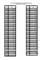
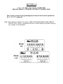
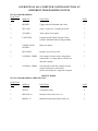
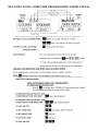
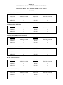
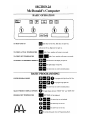
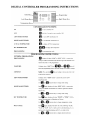
Service Manual
THE PITCO COMPLETE
Controller Guide
COVERING INSTALLATION AND
CONTROLLER PROGRAMMING
PITCO FRIALATOR, INC.
P.O.BOX 501 CONCORD, NH 03302-0501
Phone: 1(603)225-6684 Toll Free: 1(800)258-3708
Fax: (603)225-8497
Literature # L20-097 Rev 1
Rev Date 2 October 1998 Made in the United States of America
CONTENTS
FRYER TEMPERATURE PROBE OHMS RESISTANCE CHART
PASTA COOKER \ RETHERMALIZER TEMPERATURE PROBE
OHMS RESISTANCE CHART
Page (s)
10
1-12 COMPUTER CONTROLLER PROGRAMMING
3-17
11
COMPUTER ERROR TROUBLESHOOTING
18
12
COMPUTER REPLACEMENT AND INSTALLATION
19
20
McDONALDS COMPUTER CONTROLLER PROGRAMMING
20-23
21
COMPUTER ERROR TROUBLESHOOTING
24
22
COMPUTER REPLACEMENT AND INSTALLATION
25
30
DIGITAL CONTROLLER PROGRAMMING
26-27
40
PASTA \ RETHERMALIZER DIGITAL CONTROLLER
PROGRAMMING
28-29
50
RETHERMALIZER \ SOUP COOKER DIGITAL THERMOSTAT
30-31
TEMP
(°F)
50
55
60
65
70
75
80
85
90
95
100
105
110
115
120
125
130
135
140
145
150
155
160
165
170
175
180
185
190
195
200
205
210
215
220
225
ALL FRYERS TEMPERATURE PROBE OHMS
RESISTANCE CHART
RESISTANCE
TEMP RESISTANCE
(°F)
(O)
(O)
230
4,675
180,491
158,252
235
4,329
240
4,013
139,055
245
3,723
122,489
108,051
250
3,458 121 C
255
3,214
95,539
84,644
260
2,991
75,136
265
2,785
270
2,596
66,823
275
2,422
59,540
53,146
280
2,262
47,523
285
2,114
290
1,977
42,569
38,195
295
1,851
300
1,734 149 C
34,328
30,902
305
1,626
27,862
310
1,526
25,161
315
1,433
22,755
320
1,347
325
1,267
20,610
18,695
330
1,192
335
1,123
16,981
15,446
340
1,058
14,069
345
998
350
942 176 C
12,832
11,719
355
890
10,716
360
841
365
795
9,812
8,995
370
752
8,255
375
712 190 C
7,586
380
675
6,979
385
640
6,427
390
607
395
576
5,926
5,470
400
547 204 C
5,055
PASTA COOKER \ RETHERMALIZER TEMPERATURE
PROBE OHMS RESISTANCE CHART
TEMP
(°F)
70
80
90
100
110
120
130
140
150
160
170
180
190
195
200
210
212
RESISTANCE
(O)
975
1,020
1,060
1,101
1,147
1,189
1,234
1,274
1,320
1,364
1,409
1,454
1,493
1,512
1,533
1,575
1,617
SECTION 1.0
I - 8 /1 -12, 3600 INTELLIFRY COMPUTER
PROGRAMMING AND REPLACEMENT INFORMATION
This section contains all programming instructions & function descriptions for
the I - 8 /1 -12 computers.
NOTE: When replacing a computer review page 11, 3RD LEVEL PROGRAMMING, MORE SERVICE
SECTION, follow computer configuration instructions to match computer programmed settings to
fryer computer is to be installed in.
OVERVIEW OF ALL COMPUTER CONTROL BUTTONS AT
DIFFERENT PROGRAMMING LEVELS
LEVEL 2 PROGRAMMING:
FUNCTION
KEY
DISPLAY
FUNCTION
1
DEGREE
Toggles between Fahrenheit and Celsius
7
2
SET PASS
Turns on, turns off, or changes password
7
3
VOLUME #
Alarm volume level options
7
4
LANGUAGE
Language option English, Spanish, French,
German, and Dutch (others could get added)
7
5
LIQUID, SOLID,
NO MELT
Melt cycle options
7
6
RECOVERY
Displays fryer recovery times
7
7
CONTROL, TIMER
Sets computer in timer mode or temperature
control mode, on a single tank or left side on a
dual tank computer
7
8
CONTROL, TIMER
Sets right side of dual tank computer in timer
mode or temperature control mode
NOTE: Non existent in a single tank computer
7
PAGE
SERVICE MODEL
LEVEL 3 PROGRAMMING: SERVICE ONLY
FUNCTION
KEY
DISPLAY
FUNCTION
1
OFF##F
Temperature offset
8
2
MELTON: ##
Duration of time melt cycle is on
9
3
MINON: ##
Minimum time duration burners will be on
9
PAGE
FUNCTION
KEY
DISPLAY
FUNCTION
4
RECY###
Temperature recovery times
9
5
DIAGNOST
Diagnostic testing mode
10
6
READY ##
Temperature range at which "READY" will display
11
7
RANGE 1
IDENTIFIES THE TEMPERATURE RANGE THE FIRMWARE
FUNCTIONS IN .
11
8
MORE SERVICE
GIVES ACCESS TO AN ADDITIONAL SET OF SERVICE
FOLLOWING IN "MORE SERVICE" SECTION. THIS
SECTION ONLY AVAILABLE ON COMPUTERS FROM 1998
11
9
BASKET LIFTS
SETS THE NUMBER OF BASKET LIFTS CONTROLLED BY
16
PAGE
SIDE OF A DUAL TANK COMPUTER AND SETS THE
BASKET LIFTS CONTROLLED BY THE RIGHT SIDE OF A
COMPUTER
MORE SERVICE:
FUNCTION
KEY
DISPLAY
FUNCTION
1
NOW ON/OFF
COOK NOW ON FUNCTION ALLOWS SECOND BASKET
PAGE
11
TO BE STARTED WHILE OPPOSITE ALARM IS
NOW OFF BLOCKS OPPOSITE BASKET TIMER FROM
STARTED.
2
TRBO ON/OFF
MUST BE IN ON POSITION IF COMPUTER IS INSTALLED
TURBOFRY
12
3
GENERIC 1,
GENERIC2, T-STAT,
HE RPB, HE ADV
MUST BE SET TO MATCH FRYER MODEL COMPUTER IS
INSTALLED IN .
12
4
SH-DUR: ##
DISPLAYS THE SHAKE TIME ALARM DURATION
13
5
HD-DUR: ##
DISPLAYS THE HOLD TIME ALARM DURATION
13
6
CANCEL: ##
DETERMINES THE TIME DURATION A KEY MUST BE
14
DEPRESSED TO CANCEL A FUNCTION
7
CFG###F
DISPLAYS THE VALUE OF ALL THE PROGRAMMED
THAT HAVE BEEN INSTALLED (EVEN CHANGING ONE
15
FUNCTION KEY COUNT DOWN TIME WILL CHANGE THE
CONFIGURATION VALUE)
8
FACTORY RESET
RESETS COMPUTER PROGRAMMING TO ORIGINAL
SETTINGS .
15
MULTIPLE LEVEL COMPUTER PROGRAMMING INSTRUCTIONS
EXIT SECOND LEVEL PROGRAMMING MODE PRESS FUNCTION KEY.
SERVICE MODE
THIRD LEVEL PROGRAMMING
This level programming is usually factory set and does not need to be changed, the possible exception
would be when warranty or non warranty computers are being replaced.
DEFAULT
MINIMUM HEAT ON & MINIMUM HEAT OFF TIMES
MINIMUM MELT ON & MINIMUM MELT OFF TIMES
TABLES
GENERIC 1 TIME SETTINGS
MIN HEAT
MIN MELT
FUNCTION
TIME IN SECONDS
FUNCTION
TIME IN SECONDS
MIN ON
5
MIN ON
8
MIN OFF
5
MIN OFF
26
GENERIC 2 TIME SETTINGS
MIN HEAT
MIN MELT
FUNCTION
TIME IN SECONDS
FUNCTION
TIME IN SECONDS
MIN ON
5
MIN ON
8
MIN OFF
5
MIN OFF
32
T - STAT (NON TURBO) TIME SETTINGS
MIN HEAT
MIN MELT
FUNCTION
TIME IN SECONDS
FUNCTION
TIME IN SECONDS
MIN ON
5
MIN ON
8
MIN OFF
5
MIN OFF
26
T - STAT TURBO TIME SETTINGS
MIN HEAT
MIN MELT
FUNCTION
TIME IN SECONDS
FUNCTION
TIME IN SECONDS
MIN ON
20
MIN ON
8
MIN OFF
20
MIN OFF
32
HE ADV TIME SETTINGS
MIN HEAT
MIN MELT
FUNCTION
TIME IN SECONDS
FUNCTION
TIME IN SECONDS
MIN ON
10
MIN ON
15
MIN OFF
10
MIN OFF
38
MIN HEAT
FUNCTION
TIME IN SECONDS
MIN MELT
FUNCTION
TIME IN SECONDS
MIN ON
10
MIN ON
12
MIN OFF
10
MIN OFF
38
HE RPB TIME SETTINGS
SECTION 1.1
3600 Standard Computer Trouble Shooting
For Revisions 215 And Up
Definitions
NVRAM (Non Volatile Random Access Memory also known as Electronically Erasable Read Only Memory):
Memory area that can be modified during operation and retain that modified information after power is turned off
and on. The NVRAM is the area into which specific configurations are downloaded at the Pitco factory. Values are
also modified during normal operation and/ or strore-level programming.
RAM (Random Access Memory) memory that is populated on power up from the ROM (Read Only Memory) or
the NVRAM. Values are continually modified during operation but changes are not retained after power is turned
off and on.
Notes
1) RAM_Err (RAM error) indicates that corruption of the RAM has been detected on power up. If RAM_ Err is displayed,
further operation is inhibited unless error clears with turning power off and on.
2) NVM_Err (NVRAM error) indicates that the NVRAM write operation has failed. This error will change to CFG_Err upon
turning power off and on.
3) CFG_Err (Configuration error) indicates that corruption of the NVRAM has been detected. This error normally requires a
restore function to fix.
4) DFT_Err (Default error) indicates that illegal value of parameter in NVRAM has been detected on power up. If DFTJErr is
displayed alone (no associated CFG_Err), during operation, then a corruption of the RAM is indicated which will reset upon
turning power off and on.
General Information
All of these error messages will alternate with normal display except for the RAM_Err.
Any abnormal display or operation can occur if a noise event occurs which is large enough to cause a reset or
partial reset of the microprocessor. Turning power off and on should clear this type of fault.
Resetting Computer
An error reset attempt can be done by unplugging wiring harness on back of computer. If this does not reset
computer follow Factory Reset Instructions listed on page 15.
If computer will not reset replace computer
SECTION 1.2
1-12 COMPUTER REPLACEMENT AND
INSTALLATION INSTRUCTIONS
When replacing or installing the 1-12 (3600 Intellifry Computer) The computer must be
programmed to match the fryer the computer is being installed on. Note: This only
applies to Revision 207 computers and higher
If the computer is not configured to match the fryer it is being installed on improper
operation of the fryer may occur.
Remove old computer, inspect old computer for cause of failure, and ensure that front
panel components and wires are in proper order.
Install new computer and follow COMPUTER CONFIGURATION SETTING instructions
from page 12 and 13 of this manual.
SECTION 2.1
McDonalds Computer Trouble Shooting
For Revisions M62D And Up
Definitions
NVRAM (Non Volatile Random Access Memory also known as Electronically Erasable Read Only Memory):
Memory area that can be modified during operation and retain that modified information after power is turned off
and on. The NVRAM is the area into which specific configurations are downloaded at the Pitco factory. Values are
also modified during normal operation and/ or strore-level programming.
RAM (Random Access Memory) memory that is populated on power up from the ROM (Read Only Memory) or the
NVRAM. Values are continually modified during operation but changes are not retained after power is turned off
and on.
Notes
1) RAM_Err (RAM error) indicates that corruption of the RAM has been detected on power up. If RAM_Err is
displayed, further operation is inhibited unless error clears with turning power off and on.
2) NVM_Err (NVRAM error) indicates that the NVRAM write operation has failed. This error will change to
CFG_Err upon turning power off and on.
3) CFG_Err (Configuration error) indicates that corruption of the NVRAM has been detected. This error normally
requires a restore function to fix.
4) DFTJErr (Default error) indicates that illegal value of parameter in NVRAM has been detected on power up. If
DFT_Err is displayed alone (no associated CFG_Err), during operation, then a corruption of the RAM is indicated
which will reset upon turning power off and on.
General Information
All of these error messages will alternate with normal display except for the RAM_Err.
Any abnormal display or operation can occur if a noise event occurs which is large enough to cause a reset or partial
reset of the microprocessor. Turning power off and on should clear this type of fault.
Resetting Computer
An error reset attempt can be done by SOFT OFF/ ON or by unplugging wiring harness on back of computer.
Unplugging computer is a more effective way to reset.
Note: If computer is on a split VAT, right side computer plug must be reconnected first, then left or computer will
not recognize there are 2 VATS. If this does not work reset computer following Factory Reset Instructions listed on
page 21.
If computer will not reset replace computer
SECTION 2.2
McDONALDS COMPUTER REPLACEMENT
AND INSTALLATION INSTRUCTION
When replacing or installing a McDonalds computer the new computer must be
programmed to match the fryer it is being installed on (Gas or Electric).
If the computer is not programmed to match fryer it is installed in improper operation may
occur.
Remove old computer, inspect old computer for cause of failure, and ensure that front
panel components and wires are in proper order.
Install new computer and follow FRYER TYPE instructions from page 21 of this manual.
SECTION 5.0
RETHERMALIZER / SOUP COOKER
DIGITAL THERMOSTAT
PROGRAMMABLE FUNCTIONS
DF1
*
Differential temperature - Sets the temperature range above and below the set
cook temperature that the heating system cycles on and off
HI
*
Maximum controller temperature - Sets the maximum cook temperature that can
be programmed into the controller
LO
*
Minimum controller temperature - Sets the minimum cook temperature that can
be programmed into the controller
CAL
*
Calibration range - Enables calibration corrections to be made between actual
temperature and sensed temperature at the probe
SP1
*
Set temperature mode - Set temperature is programmed in this mode
ENTERING PROGRAMMING MODE
A JUMPER WIRE MUST BE INSTALLED BETWEEN TERMINALS +5 AND -3 ON THE BACK OF
THE CONTROLLER. CONTROLLER IS NON-PROGRAMMABLE WITHOUT JUMPER WIRE
INSTALLED
SAVE / EXIT PROGRAMMING MODE
TO SAVE OR EXIT PROGRAMMING MODE AT ANY TIME PRESS F UNTIL DISPLAY SCREEN IS
BLANK AND THEN REMOVE JUMPER WIRE.