1
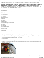
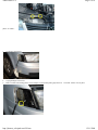
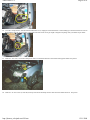
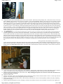
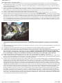
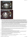
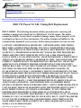
2000 Passat V6 2
Search:
Page 1 of 10
The Web
Tripod
Report Abuse
«
Starting a franchise
Previous
|
Top 100
|
Next
»
share: del.icio.us | digg | reddit |
furl | facebook
Ads by Google
Lowest Prices on VW's
Experience the Gallery difference Route 1 the Auto MIle
www.vwgallery.com
Phat Cat's Home Page including Mr.Ed Fantasy Football League
2000 VW Passat V6 2.8L Timing Belt Replacement
DISCLAIMER: The following document outlines procedures for removing and
installing a timing belt/toothed belt in a 2000 Passat V6 2.8L engine. The author
assumes no liability for any direct or indirect damage, injury, loss of property or life
resulting from the use of these instructions. The author assumes no liability for the
contents of this document or its accuracy. Follow these procedures at your own risk.
I AM NOT A PROFESSIONAL MECHANIC. AFTER READING THIS TIMING
BELT REPLACEMENT PROCEDURE, YOU WILL UNDOUBTEDLY REALISE
THIS. THE STEPS OUTLINED IN THIS ARTICLE ARE PROBABLY NOT THE
SAME WAY A PROFESSIONAL MECHANIC WOULD DO THIS PROCEDURE.
THESE ARE THE STEPS I DID ON MY OWN CAR, A 2000 VOLKSWAGEN
PASSAT WITH A V6 2.8 LITRE ENGINE. I HAD NEVER DONE A TIMING BELT
JOB ON ANY MAKE OR MODEL CAR PRIOR TO THIS. I DO NOT KNOW THE
CORRECT TERMINOLOGY OF PROFESSIONAL MECHANICS. READ THIS
ARTICLE IN ITS ENTIRETY BEFORE COMMENCING TO DO YOUR OWN
TIMING BELT JOB. IF YOU ARE UNSURE OF ANYTHING I STATE, YOU MAY
NOT WISH TO PROCEED. THIS IS FREE INFORMATION MAKING NO
GUARANTEE OF SUCCESS. I AM MERELY TRYING TO BE HELPFUL TO THE
OTHER SHADE-TREE MECHANICS OUT THERE WHO DO NOT WANT TO PAY
OUTRAGEOUS LABOR RATES FOR POSSIBLY MARGINAL QUALITY OF
AUTOMOTIVE REPAIRS. DO NOT RELY ON THIS INFORMATION TO BE
TOTALLY ACCURATE. I USED THE ROBERT BENTLEY SERVICE MANUAL ,
AUDI/VW RELATED SITES, AND INFORMATION I GATHERED FROM
SEVERAL INTERNET MESSAGE BOARD SITES. I SPENT MORE HOURS THAN
I COULD KEEP TRACK OF SEARCHING FOR THE INFORMATION I USED. I
HAVE TRIED TO BE AS ACCURATE AS POSSIBLE. IF YOU THINK THE
INFORMATION PROVIDED IN THIS ARTICLE IS NOT HELPFUL OR IS
INSUFFICIENT TO DO THE JOB PROPERLY, DO NOT RELY ON IT. IN OTHER
WORDS, IF YOU CAN DO BETTER ON YOUR OWN, DO IT. DON’T BLAME ME
IF YOU USE MY INFORMATION AND SOMETHING GOES WRONG WITH
YOUR TIMING BELT REPLACEMENT ON A 2000 VOLKSWAGEN PASSAT
WITH A V6 2.8 LITRE ENGINE.
http://phatcat_ed.tripod.com/V6.htm
12/11/2008
2000 Passat V6 2
Page 2 of 10
A DIGITAL CAMERA WAS NOT AVAILABLE WHILE I WAS DOING THE
TIMING BELT REPLACEMENT. I PROCURED ONE AFTERWARDS—THAT IS
WHY PICTURES ARE NOT INCLUDED OF ALL PARTS LOCATIONS AND
STEPS OF THE PROCEDURE THAT YOU MAY WISH WERE AVAILABLE. I
ALSO WISH THAT WERE THE CASE.
NOW THEN……………………………………………………
Tools used
T-20 Torx socket
T-20 Torx screwdriver
T-25 Torx socket
T-30 Torx socket
T-45 Torx socket
Phillips head screwdriver
10mm socket
13mm socket with extension
17mm socket
5mm Allen key
10mm Allen socket
12 inch adjustable wrench or a 32mm wrench
Strap wrench or VW special tool 3212
6mm Allen socket
6mm Allen key
5mm Allen socket
VW Camshaft Pulley puller
24mm 12 point socket, ½”drive
10mm wrench
VW special tool 3242
8mm Allen socket
VW special tool 3391 camshaft clamp
Torque wrench(s).
Use zipper-lock plastic bags for screws, bolts, small parts, etc and label them with masking tape or develop your own
organizational system for the hardware and parts.
1.
2.
3.
4.
5.
6.
Put front wheels on car ramps. Apply parking brake. Block rear wheels.
Disconnect battery.
Remove plastic bottom engine shield.
Remove 3 T-20 Torx head screws holding plastic wheel liner to bumper cover, each side. There are several more Torx screws in the wheel
liner but only these three need removed. (T-20 Socket). See photo, circles.
Remove T-20 Torx head screw holding plastic wheel liner and bumper cover to fender, each side. (T-20 screwdriver or socket with small
extension). See photo, arrow.
Remove 2 Phillips screws, yellow circles in photo, holding air cleaner intake to the top of the “engine cowl area” and remove two segments of
http://phatcat_ed.tripod.com/V6.htm
12/11/2008
2000 Passat V6 2
Page 3 of 10
plastic “air intake“.
7.
Unclip turn signal lenses.
8.
9.
Unplug headlight connections.
Remove 10mm bolts holding plastic cover to bumper, located under parking light lens area. 1 each side. Yellow circle in photo.
http://phatcat_ed.tripod.com/V6.htm
12/11/2008
2000 Passat V6 2
Page 4 of 10
10. Remove 2 phillips head screws holding black rubber “hold-downs” to top of bumper cover. Located front, top, middle(one general location,
not three different areas) normally hidden by car hood of car. Indicated inside the square in the photo.
11. Remove 3 T-25 Torx screws from front of hood lock area.
12. Remove hood-release lever from hood lock. Hint: With small flat-head screwdriver gently pry retaining clip off of pin that holds the plastic
release lever to the lock mechanism. Using snap ring pliers (even though there is no snap ring), spread the two arms of the release lever apart
and off of the pin on the release mechanism.
13. Remove bumper cover. Work gently- - work from side to side trying to pull the cover straight.
14. Remove bumper carrier using 13mm socket and extension.
15. Remove bumper guides using T-25 Torx socket and extension. Remove 2 or 3( I had 2 but Bentley shows 3) screws from each bumper guide.
(Looking from directly in front of each headlight, the screws are below the headlight facing you). Use screwdriver to gently pry bumper guide
plastic retaining clips(actually part of bumper guide, built-in if you will) from fender (2 each side).
16. Remove air temperature sensor from the bracket connected to the power steering cooler lines. Remove the retaining clip holding the air
temperature sensor line to the front of the radiator. Feed air temperature sensor wiring to the rear of the radiator up into the engine compartment.
Make notes of the path the wiring follows. See picture after step 17.
17. Remove power steering cooler line from the front of the AC radiator by removing the 2 bolts using 10mm socket with extension. I moved it
under the engine and gently hooked it out of the way on the lower engine protector support. See picture.
http://phatcat_ed.tripod.com/V6.htm
12/11/2008
2000 Passat V6 2
Page 5 of 10
18. Remove 3 10mm bolts holding hood-release lock mechanism to lock carrier.. Move the hood release lock mechanism out of your way. Hood
release cable does not have to be removed from hood release lock mechanism.
19. Remove coolant reservoir filler cap. Open radiator drain. Some suggest replacing the drain and gaskets with new.
20. Pull up upper coolant hose retainer clip (do not remove). Remove upper coolant hose from radiator. Caution: This is a little bit tricky. Be very
careful. From area in front of car between radiator and headlight, you can use a flat-head screwdriver as a helper to gently push, not pry, the
hose off of the radiator connection alternating from top to bottom. Completely remove by gently wiggling the hose up and down while pulling
away from the radiator connection. (Suggestion: plug the end with a shop towel after disconnection to eliminate dripping)
21. Unplug electrical connection to radiator fan thermo switch from lower coolant hose. Do not unplug the plastic horseshoe clip that holds the
thermo switch into the radiator hose. Pull up lower coolant hose retainer (do not remove). Remove lower coolant hose from radiator using a
similar method as that to remove the upper coolant hose. The lower coolant hose is not as accessible from the front of the car as the upper
coolant hose so you probably can’t use a screwdriver to help push. Keep face away from area directly underneath hose once you feel the hose
coming off the radiator. If it comes off quickly and unexpectedly, you will end up wearing some pink coolant in your hair and face.
22. Reinstall the coolant reservoir cap.
23. Close radiator drain.
24. Unplug wire that runs from engine side of radiator on the passenger side. It connects to a connector emanating from above the oil pan to the
rear of the alternator. Plastic cable tie may hold this line with another wire to the oil pan. If so, cut cable tie. Be careful not to cut black
shielded wires.
25. Remove black cover located to the right of the oil filler cap, left of power steering reservoir, front of ABS box, and rear of the driver’s side
headlight.
http://phatcat_ed.tripod.com/V6.htm
12/11/2008
2000 Passat V6 2
Page 6 of 10
26. From the “wiring harness” located underneath this black cover, unplug the connectors that have wires leading up to the area between the viscous
fan and electric AC fan. It is necessary to also make sure these wires do not get caught or tangled in anything when you initiate step 30 below.
27. Remove 2 Torx T-30, 1 each side holding lock carrier to bracket that attaches to front frame that supports fenders. See picture.
28. Remove T-30 Torx screws (1 each side) from top of front-end assembly where it meets the inner fender hood area. See picture.
http://phatcat_ed.tripod.com/V6.htm
12/11/2008
2000 Passat V6 2
Page 7 of 10
29. Using T-45 socket, remove bolts holding lock carrier to front end frame. Mine had 4 on the passenger side, 3 on the driver’s side. We are now
ready to remove, not just pull lock carrier into service position. I am not using the Bentley manual “lock carrier into service position” procedure
here. This seemed almost as easy -- no special tool required. Upon further evaluation after reworking some things (my cut wires fiasco) that
needed front end access, you can insert the two bolts that attach the inner bumper support into the two holes designed for the VW special tool
3369. DaddyMatt in Club B5 used this technique on his 1.8 turbo. I didn’t quite understand at the time, but having since been in the lock carrier
several times, I do now. Be careful not to rake these bolt threads with the lock carrier if you use them to support the lock carrier after pulling it
into service position. A way to avoid raking the threads would be to encase the bolts in steel sleeves from the hardware store. That would let the
lock carrier rest with less stress on the bolt threads. Be sure to support the weight of the lock carrier with a device of some sort. Being more
familiar with the lock carrier and the timing belt area now, I would still recommend the method described below to remove the lock carrier
instead of pulling it into service position. The extra room and view prove more than helpful in working on the pulleys and belts.
30. CAUTION!!!! As you are doing the following step, make sure you have a good grip on the lock carrier/radiator section and make sure
you have a support ready on which to set the lock carrier/radiator. I merely had the carrier resting on its brackets and engine snub and it fell
forward which stressed the wires between the fans and apparently broke some of the plastic clamps securing the wires. After reassembly of the
whole front end and successful starting of car, all of these wires came loose and got caught in the viscous fan resulting in many cut wires and a
burnout of the Fan Control FC module and damage to the viscous fan clutch. This added an extra $450+ in parts and more time than you want to
know (weeks of troubleshooting unknown problems caused by the cut wires, i.e the fan clutch and a 40 amp fuse in the auxillary fuse panel). If I
had secured the lock carrier as I cautioned you above, I would have saved myself a lot of hassle and money. Ok, now for the actual
step.
Slowly pull lock carrier/radiator section forward a
couple of inches off of the frame and engine snub and swing the driver side outward like a door with hinges on the passenger side. There is no
hinge on the left side and there are still hoses and wires connected to the left side. Be careful not to disconnect them or damage them. Support
the lock carrier in a very, very upright position. You do not want it to fall backward or forward or downward. I used a board to not let it fall
backward.
31. Remove top three sections of black engine cover.
32. Using 17mm socket, turn accessory belt tensioner bolt clockwise to release tension. While tension is relieved, still holding pressure clockwise,
insert a 5 mm Allen wrench (or other suitable device to use as a pin) through the holes that will line up at the top left of tensioner.
33. Remove accessory belt tensioner using 10mm Allen socket. Keep retaining pin in postion. Do not remove it and relieve the tension. You
need it in this position to reinstall.
34. Remove accessory belt.
35. Remove viscous fan. I used a 12 inch adjustable wrench for the fan nut (32mm), which is turned clockwise to loosen. I used a strap wrench to
grasp the viscous fan pulley in lieu of using VW special tool 3212 spanner.
36. Remove fan retainer using 6mm Allen socket , 6mm Allen key, and 5mm Allen socket on the bolt partially hidden by fan pulley, depending
upon position of pulley..
37. Remove upper three timing belt covers by unclipping. Passenger side, middle, and driver side. The middle one may take some wiggling and
http://phatcat_ed.tripod.com/V6.htm
12/11/2008
2000 Passat V6 2
Page 8 of 10
careful, gentle cajoling—kind of like a puzzle.
38. NOTE: I have a five speed manual transmission. It needs to be in neutral with parking brake engaged. I don’t know what difference an
automatic transmission makes. Use a 24 mm 12 pt socket to turn the crankshaft pulley/vibration damper clockwise to line up timing marks on
lower timing belt shield and crankshaft pulley. The mark on the crankshaft pulley is a vertical line stamped into its edge. There is an arrow on
the plastic timing belt shield.
39. There are two holes in each camshaft pulley, one larger than the other. All four holes should be on a straight horizontal line at this point. The
larger two holes need to be towards the inside of the engine. If the larger holes are towards the outside of each pulley (towards the fenders), turn
the crankshaft pulley until the larger holes of the camshaft pulleys are on the inside position of each pulley in a linear position.
40. Remove 8 bolts holding crankshaft pulley/vibration damper using 6mm Allen socket.
41. Remove two bolts holding lower timing belt shield, which is located behind the crankshaft pulley you just removed. Use 10 mm socket.
42. Remove 10mm bolt from sealing plug located in lower driver side of cylinder block. See picture below. Line yourself up with the camera
angle and you will be able to find the sealing plug. It’s kind of on the under side of the block to the rear of the AC compressor. Remove sealing
plug and o-ring. You have to work in a small area doing this. I used a 10mm wrench. Thread in VW tool 3242 clamping tool. This makes sure
the crankshaft doesn’t move while you’re working on the timing belt and camshaft pulleys. Use a mirror and light to look into the sealing plug
hole. The indentation/divot/crater must be visible to ensure you are at TDC(top dead center). Another way to think of this “marker” is to think
of a circular dimple that the inserted rounded end of special tool 3242 would fit into like a glove. Sorry, that’s the best description I can give. If
you see it, you’ll know it, in my opinion.
43. Insert 8mm Allen socket into timing belt tensioner and turn socket clockwise to compress tensioning lever until you can insert a holding pin
through the silver/chrome piston housing and tensioner piston. I used a 6D finishing nail grinded down, cylindrically(??), until it fit into the
holes.
44. Remove timing belt, note direction of rotation if not installing new timing belt. You don’t want to run the belt backwards for the same reason as
not doing it to radial tires.
45. If replacing timing belt tensioner with new one, do so now using 6mm Allen socket. Replacing appears to be the recommendation.
46. If replacing, remove idler roller using 17 mm socket and replace with new one. Skip this step if not replacing idler roller.
47. I didn’t remove either camshaft sprocket although the Bentley manual indicates to do this. I didn’t do it because their reasoning and subsequent
steps did not appear to me to be clear or complete. Just my opinion. UPDATE: In October 2003, I did the timing belt on my 2001 TDI
Golf. It only has one camshaft pulley and I pulled it per the instructions I got from another website. Now, I see that I could have pulled
the V6 camshaft pulley to allow for easier installation of the timing belt even though I got it installed tightly without doing that.
48. Remove timing belt, but be careful if you have to use any “force” so you don’t perhaps move something. Just a caution.
49. Install new timing belt starting at crankshaft sprocket, then idler roller, right cam pulley, water pump pulley, and left cam pulley. After you get
the belt over these, even though not necessarily all the way on, install camshaft clamp onto camshaft pulleys. Remember, the big hole/small hole
instruction? This clamp will remind you if you forgot or considered it unimportant.
50. OK, now when I was fitting this clamp on. It wasn’t exactly robotic precision in how it fit the camshaft pulleys. If I installed the left side first,
it’s fit was closer to linear than if I had started with the right pulley. This gave me reason to pause. I reinstalled my bottom timing belt shield and
crankshaft pulley and the timing marks still looked accurate. By eyeballing, the camshaft pulley holes appeared linear (straight line). I went
back and forth in my thinking about the fit of the clamp. End result decision after asking some questions in Club B5: timing marks lined up,
camshaft holes were linear in appearance, and clamp could be installed (albeit with a little give of the clamp and slight revolution of cam pulley)--Should be fine. See pictures below. These were taken after I had to go back into the patient and repair the wires that had been damaged by the
viscous fan. The pictures replicate exactly the same situation as when I was in the first time and feeling unsure about how things looked. After
you get in there first hand and see how these camshaft pulleys feel with compression on them, you will have a better idea of the difficulty of
knowing if I had done it correctly. You can’t turn the camshaft pulleys very far without compression releasing and the pulley moving about an
entire quarter of a turn when all you wanted was a tooth or so. I ended up feeling I was as close as I could get because I made the mistake of
turning the camshaft pulley too far and had to turn it backward, feeling compression release again, and then turning forward again just enough
to get back to my starting point where my camshaft pulley holes were to begin with. That’s when I decided I would proceed with almost perfect
linear position. The camshaft clamp picture shows pretty much what I was dealing with. If I were to remove that clamp from the right and put it
on the left pulley, it would not seem as out of linear position.
http://phatcat_ed.tripod.com/V6.htm
12/11/2008
2000 Passat V6 2
Page 9 of 10
51. After I reinstalled everything and started up the engine—it ran like a clock. Just wanted to spend some time on this point because it
was where I began to doubt if I was on the right track doing this job myself. Having said that, maybe you won’t be in the same frame of
mind that I was at this particular point, maybe you won’t have as much confidence in how things had advanced to this point, maybe
you won’t be feeling lucky, maybe a lot of things will make you think differently at this point. I felt confident, not necessarily lucky, but
I went for it. Just don’t proceed if you don’t feel good about things done so far. Remember: This is free, untrained, amateur advice and
I have spent time and effort to make sure it’s a solid step-by-step report as I did it and then did a lot of this procedure to fix some wires
that were cut after reassembly the first successful time. This was the first and only time I had been into my car’s mechanical workings to
this involved extent. I will try to fix most anything that breaks—car, garden tractor, plumbing, electrical, well pump, etc. I have ended
up spending more money to try repairs on my own than having a trained professional do the job.
52. Ok, so I now need to get the belt on the camshaft sprocket teeth. I put a little downward pressure on the new belt just to the left of the water
pump pulley to get a better idea where the belt teeth should be on each camshaft pulley. I did this because there is no tension applied to the belt
at that point. The timing belt tensioner is not exerting pressure and I didn’t want to possibly end up with “slack” in the belt. This step is very
important and you need to kind of finesse the belt onto the camshaft pulleys for a snug fit. This is probably why Bentley states to remove
one/both (I wasn’t clear) camshaft sprockets. I can see how it would be easier to get the belt on, but you still have to reinstall the pulleys in a
snug position on the belt’s teeth. It may also be helpful to remove the camshaft clamp at this point to give yourself a little wiggle room to get the
new belt seated properly if you can’t succeed at it with the clamp in postion. This is where I wasn’t sure if I even needed to buy the camshaft
clamp 3391.
53. Slowly, carefully, take tension off tensioner, remove holding pin, and release tension back onto timing belt. Bentley manual states to torque
timing tensioner, not the bolt that holds the tensioner to the car, but the Allen hole (using 8mm Allen socket) to 15 Nm/11 ft lb.
54. Replace lower timing belt shield to 10 Nm/7 ft-lb.
55. Replace crankshaft pulley/vibration damper to 25 Nm/18 ft-lb.
56. Timing marks on shield and pulley should still be in alignment
57. Remove clamping bolt VW tool 3242 from sealing plug and reinstall plug. Don’t know torque value.
58. Using 24mm socket, turn engine slowly until the big holes on the camshaft pulley turn 360 degrees twice. Listen and feel for abnormalities. I
don’t have a better description of what that would feel or sound like, sorry. Since I was successful, as it turned out, I didn’t get a chance to
experience the feel of an abnormally aligned timing belt or camshaft/crankshaft abnormal positions.
59. Timing marks should still be in alignment. If not, at this point, you need help and advice I cannot give.
60. If you believe the belt is on correctly, proceed to reassemble.
61. Reinstall timing belt covers: driver, middle, passenger.
62. Reinstall viscous fan pulley retainer. M8 bolts to 25Nm/18 ft-lb. M6 bolts to 10Nm/7ft-lb.
63. Reinstall viscous fan. Unsure of torque value. Bentley gives 2: “without VW torque wrench 1331….70 Nm/52 ft-lb. “with VW torque
wrench 1331….37 Nm/27 ft-lb.”
64. Reinstall accessory belt tensioner to 55 Nm/41 ft-lb, but do not remove holding pin.
http://phatcat_ed.tripod.com/V6.htm
12/11/2008
2000 Passat V6 2
Page 10 of 10
65. Install new accessory belt in this order: crankshaft pulley, AC compressor, viscous fan pulley, power steering pulley, alternator/generator, and
tensioner. Make sure belt is seated on all pulleys correctly. Relieve tension on tensioner, pull retaining pin and slowly release tension onto belt.
66. Remember my cut wire scenario at this point and double/triple/quadruple check that the wires running between the radiator fan and viscous fan
are securely out of the way of any interference with the fans. Make sure the clamps holding them still have integrity. Maybe reinforce with wire
tie-downs. Put lock carrier back into frame supports and engine snub and secure somehow so it will not slide off and suffer any damage. I used
the Torx screws from the picture referenced earlier in steps 25 and 26. You could re-bolt it on at this point, but if anything needs redone it’s just
another step to undo. If you do re-bolt it on at this point, make sure you have your turn signal and headlight wires free and clear from the grip of
the lock carrier so the wires don’t get pinched.
67. Reinstall upper coolant hose and lower coolant hose. Make sure you get them all the way on and the clip seated entirely.
68. Reconnect all of the wiring harness connections. The ones near the ABS box.
69. Reconnect radiator fan thermo switch electrical connector to lower radiator hose.
70. Reconnect wire that goes above oil pan to a connector.
71. Reinstall power steering cooler line and air temperature sensor that mounts in the clamp on the cooler line.
72. Refill coolant reservoir with new coolant (G12). You have to watch this because you may think the coolant system is full but, it may actually
still be thirsty. Keep checking level periodically after car is started and running. Check for leaks, abnormal sounds, check AC, check that fan
comes on when AC is running. In short, check for normal running conditions prior to timing belt job.
73. Re-bolt lock carrier to frame. Hint: Use bolt pattern grime as reference marks so parts go back in the same position from which they came.
The grime that developed around the bolt and screw heads from normal wear should give you an indication of where you want the bolts and
screws reseated to duplicate the fit you had before you started this job. Make sure your turn signal wires are routed correctly.
74. Reinstall wiring harness black cover.
75. Reinstall hood release lock mechanism bolts to 12 Nm/9 ft-lb. Bentley says use locking fluid if reusing these bolts. If not reusing, clean bolt
threads and nut threads with thread tap.
76. Reinstall bumper guides to 2 Nm/18 in-lb.
77. Reinstall bumper carrier to 20 Nm/15 ft-lb.
78. Reinstall bumper cover. Recheck your turn signal wires aren’t being pinched.
79. Reinstall hood release lever and guide.
80. Reinstall air intake plastic pieces.
81. Reinstall turn signals.
82. Reconnect headlight connections.
83. Reattach plastic wheel liners.
84. Reinstall engine manifold covers (3 pieces).
85. Reinstall plastic bottom engine shield
86. Reconnect battery.
Ads by Google
Allen Wrench
Timing Belt Basics
Engine Timing Chain Kits
Top VW Passat Prices
Bargain Prices. Smart Deals.
Everything You Need to Know Car
Care Articles and Illustrations
Camshaft Timing Belt Components
Tensioners Gears Chain Guides Cams
Find out our Lowest Possible Price on
a new 2008 Volkswagen Passat!
www.autoMedia.com
www.japanengine.com
www.CarPriceSecrets.com
Shopzilla.com
http://phatcat_ed.tripod.com/V6.htm
12/11/2008