1
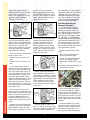
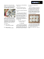
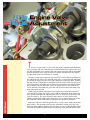
2.5 Liter
Twin Cam
Engine Valve
Adjustment
T
he first versions of the 2.5 liter twin cam engines employed non-hydraulic
valve actuation. Like the timing belt, the clearance between the engine valves and
the shim and bucket valve actuators does not require inspection and/or adjustment
until 105,000 miles have elapsed. However, various circumstances may require
an adjustment before that milestone is reached.
Clearance is tight (sorry about the pun) and there is little room to work between
the cylinder heads and the left and right frame rails. A special tool (ST 49818700)
is available for depressing the valves and removing the adjusting shims. Without
this tool, the job is impossible to accomplish with the engine in the car. Once again,
we had the benefit of working on an engine that had already been removed from
the car. Before you can adjust the valves, the engine must be cold. Consult the
service manual to determine the parts that will need to be moved or removed to
make some room to work.
Both right side resin camshaft sprockets have a single arrow embossed on their
front surfaces. The position of these arrows determines which valves are to be
measured and/or adjusted. To begin the procedure, turn the crankshaft pulley clockwise until the camshaft sprocket arrows are pointing to the position shown in the
The
End Wrench
Unlike some overhead cam engines that require you to rotate the cam until
each cam lobe is facing 180 degrees away from the adjustment shim, Subaru has
very specific procedures for adjusting four valves at a time (a pair of intakes and
a pair of exhausts). The pairs of intakes and exhausts are never for the same
cylinder, which makes things rather interesting. This system requires you to turn
the crankshaft a total of four times to complete the adjustment procedure.
20
figure below (approximately 2
o’clock position). In this position,
the #1 intake valve and #3
exhaust valve clearances can be
inspected and the clearance
adjusted as necessary.
position shown in the figure
below (approximately 4 o’clock
position). In this position, the #2
exhaust valves and the #3 intake
valves can be measured and/or
adjusted if necessary.
Just remember, if a valve requires
adjustment, make sure the camshaft
sprockets are in the proper position before attempting to depress
the valve or remove a shim. This
will prevent any unintentional
valve interference problems.
Valve Adjustment Tool and
Adjustment Procedures
Insert a thickness gauge between
the heel of the camshaft and the
adjusting shim. Keep the thickness
gauge as close to parallel with the
shim surface as possible. The
exhaust valve clearances are more
easily measured while working
from beneath the vehicle.
The valve clearance specifications
for these engines are:
Next, rotate the crankshaft pulley
clockwise until the right side
camshaft sprockets are in the
position shown in the figure
below (approximately 8 o’clock
position). In this position, the #2
intake valves and the #4 exhaust
valves can be measured and/or
adjusted if necessary.
• Attach the second half (part B)
to part A by sliding its pins
through the slotted holes in part
A.
• Exhaust valves 0.25 mm ± 0.02
mm.
The
End Wrench
• Install the eccentric bolt (part C)
into the hole in part A.
Finally, rotate the crankshaft
pulley clockwise until the right
side camshaft sprockets are in the
position shown in the figure below
(approximately 10 o’clock position).
In this position, the #1 exhaust
valves and the #4 intake valves
can be measured and/or adjusted
if necessary.
The eccentric bolt forces parts
A and B away from one another.
Because part A can’t move (it’s
wedged against the cam lobes), the
only thing that can move is part B.
Part B moves by forcing the shim
buckets downward, away from the
camshaft.
If the clearance for any of the
first set of valves is more than 0.02
mm beyond the specification, write
down the actual clearance. You’ll
need the information later to
determine which shim to install
to bring the clearance into specification.
Continue the measurement procedure by rotating the crankshaft
pulley clockwise until the right
side camshaft sprockets are in the
The tool installed in the three
steps:
• Wrap the first half of the tool
(part A) around the lobes.
• Intake valves 0.20 mm ± 0.02
mm.
An assortment of 60 shims is
available, in 0.01 mm increments,
so it’s theoretically possible to get
each valve adjusted to exactly its
clearance specification. But if the
valve adjustment is within 0.02
mm of the specification, do not
remove the shim. Changing a single
shim size will only bring it 0.01
mm closer to perfection. Moving
up (or down) two sizes may cause
you to overshoot the specification
on the other side.
As we mentioned, it takes a
special tool to work within the
limited clearance area between
the cylinder heads and the frame
rails. The ST 498187 is a threepart tool. One part wraps around
the cam lobes, a second touches
the outer edges of two shim buckets,
and a third eccentric bolt exerts
the necessary pressure to push a
pair of shim buckets away from
the cam lobe to make shim removal
and replacement possible.
You may prefer to adjust the
valves as you go, or measure them
all before returning to adjust those
valves that require adjustment.
22
Each shim bucket has a notch
cut into its edge to facilitate shim
removal. With the shim replacer
tool locked into position, use a
dental pick to force the adjusting
shim out of its slot in the shim
bucket. Use a needle-nosed pliers
or magnet to lift the shim clear of
the shim bucket and camshaft.
S equals the new shim thickness
to be used.
0.25 mm, the recommended
clearance.
V equals the measured valve
clearance before adjustment.
When reinstalling the adjustment
shim, always position the shim so
its number side faces away from
the cam lobe. This will keep the
cam lobe from wearing the numbering away, which will make it easier
to identify the shim the next time
it needs to be removed.
T equals the original shim thickness.
Use a micrometer to measure the
thickness of the removed shim.
Here’s where your earlier clearance
measurements come into play. To
determine the required replacement
shim thickness use the following
formulas for intake and exhaust
valve shims.
For intake valves:
S = (V + T) - 0.20 mm
For exhaust valves:
S = (V + T) - 0.25 mm
Let’s plug in some numbers to
see how it works. Let’s say our
measured valve clearance for an
exhaust valve was 0.30 mm.
That’s more than 0.02 out of specification, so an adjustment is
required. When we remove the
existing shim, we find that it is
2.38 mm thick.
S = (0.30 + 2.38) - 0.25
S = 2.68 - 0.25
S = 2.43 mm
So the replacement shim (2.43
mm) is exactly 0.05 mm thicker
than the original shim. This will
reduce the valve clearance by 0.05
mm, which will put it exactly at
As the old saying goes, reassembly
is the reverse of disassembly. There
are no special tricks along the way.
Do it like the carpenters do —
measure the shim twice, replace it
once.