1
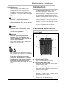
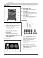
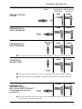
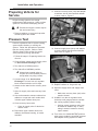
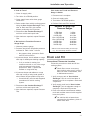
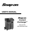
SUN
®
USER’S MANUAL
Sun Coolant
Exchange™
Drain and Fill
with Continuous Flush
Sun Coolant Exchange™
User’s Manual
Table of Contents
Safety ................................................ 2
Introduction ...................................... 5
Functional Description ..............................
Front Panel ........................................
Back Panel ........................................
Control Panel ......................................
Accessories ........................................
Control Panel Key Terms ....................
Specifications ..........................................
5
5
6
6
6
7
7
Installation and Operation .............. 7
Testing Tips ........................................ 7
Valve Position Chart ................................ 8
Preparing Vehicle for Service .................. 10
Pressure Test .......................................... 10
Drain and Fill .......................................... 11
Continuous Flush .................................... 13
Power Drain Recovery Tank .................... 14
Recycle Used Coolant from Recovery
Tank ...................................................... 14
Maintenance .................................... 14
Recovery Hose Strainer ............................
Cleaning Recovery Hose Strainer ..........
Changing Filter Cartridges on
Optional Recycler Hit ............................
Replacement Parts ................................
Optional Accessories ........................
Troubleshooting ......................................
14
15
Trademark Acknowledgements
Snap-on® is a registered trademark of Snap-on
Technologies, Inc. (USA and Canada)
EquiServ® is a registered trademark of Snap-on
Tools Company. (USA)
EquiServ® is a registered trademark of Snap-on
Technologies, Inc. (Canada)
Sun Coolant Exchange™ is a trademark of
Snap-on Technologies, Inc. (USA and Canada)
Copyright Information
Sun Coolant Exchange™ User’s Manual ©2002
Snap-on Technologies, Inc.
The information, specifications and illustrations in
this manual are based on the latest information
available at the time of printing. Snap-on
Technologies, Inc. reserves the right to make
changes at any time without notice.
15
16
16
17
Table of Illustrations
Introduction
Figure 1: Front Panel .............................. 5
Figure 2: Back Panel .............................. 6
Figure 3: Control Panel ............................6
Figure 4: Sun Coolant Exchange™
Accessories .............................................. 6
Installation and Operation
Figure 5: Recovery Hose and Adapter
Attached to Radiator .............................. 10
Figure 6: Supply Hose and Adapter
Attached to Engine ................................ 10
Table 1: Cooling System Pressure
Ranges .................................................. 11
Maintenance
Figure 7: Strainer Assembly .................. 15
1
Safety Information
Safety Information
Safety Notice
For your safety, read this manual thoroughly
before operating your Sun Coolant
Exchange™ unit.
Your Sun Coolant Exchange™ unit is
intended for use by properly trained, skilled
professional automotive technicians. The
safety messages presented below and
throughout this user's manual are reminders
to the operator to exercise care when using
this unit.
There are many variations in procedures,
techniques, tools, and parts for servicing
vehicles, as well as in the skill of the
individual doing the work. Because of the
vast number of test applications and
variations in the products that can be
serviced with this instrument, Sun® cannot
possibly anticipate or provide advice or
safety messages to cover every situation. It
is the automotive technicians responsibility
to be knowledgeable of the system that is to
be tested. It is essential to use proper
service methods and test procedures and to
perform tests in an appropriate and
acceptable manner that does not endanger
your safety, the safety of others in the work
area, the vehicle or equipment being tested.
It is assumed that the operator has a
thorough understanding of vehicle cooling
systems before using the Sun Coolant
Exchange™ unit. This understanding of
principles and operating theories is
necessary for competent, safe and accurate
use of this instrument.
Before using your Sun Coolant
Exchange™ unit, always refer to and follow
the safety messages and applicable test
procedures provided by the manufacturer of
the vehicle or equipment being tested.
Read All Instructions
Read, understand and follow all safety
messages and instructions in this manual.
Safety messages in this section of the
manual contain a signal word with a threepart message and, in some instances, an
icon.
2
The signal word indicates the level of the
hazard in a situation.
DANGER
Indicates an imminently hazardous situation
which, if not avoided, will result in death or
serious injury to the operator or bystanders.
WARNING
Indicates a potentially hazardous situation
which, if not avoided, could result in death
or serious injury to the operator or
bystanders.
CAUTION
Indicates a potentially hazardous situation
which, if not avoided, may result in
moderate or minor injury to the operator or
bystanders.
IMPORTANT
Indicates a situation which, if not avoided,
may result in damage to the equipment or
vehicle.
Safety messages in this section contain
three different type styles.
• Normal type states the hazard.
• Bold type states how to avoid the hazard.
• Italic type states the possible
consequences of not avoiding the hazard.
An icon, when present, gives a graphical
description of the potential hazard.
Safety Information
IMPORTANT SAFETY
INSTRUCTIONS
General
WARNING
Risk of fire.
• Wear safety goggles and protective
gloves, user and bystander. Everyday
eyeglasses only have impact resistant
lenses, they are NOT safety glasses.
• Do not position head directly over or in
front of carburetor or throttle body.
Engine backfire can occur when air
cleaner is out of normal position.
• Keep a dry chemical (Class B) fire
extinguisher rated for gasoline,
chemical electrical fires in the work
area.
Fire can cause death or serious injury.
WARNING
Risk of entanglement.
• Do not place test equipment or tools
on fenders or other places in engine
compartment.
• Keep yourself, clothing and tester
leads clear of moving parts such as
fan blades, pulleys, hood and doors.
• Barriers are recommended to help
identify danger zones in test area.
• Prevent personnel from walking
through immediate test area.
Contact with moving parts can cause injury.
WARNING
WARNING
Risk of expelling fuel, oil vapors, hot steam,
hot toxic exhaust gases and other debris.
• Wear safety goggles and protective
clothing, user and bystander.
• Engine systems can malfunction
expelling fuel, oil vapors, hot steam,
hot toxic exhaust gases and other
debris.
Fuel, oil vapors, hot steam, hot toxic
exhaust gases, and other debris can cause
serious injury.
WARNING
Risk of burns.
• Do not touch hot exhaust systems,
manifolds, engines, radiators, etc.
• Wear gloves when handling hot engine
components.
Hot components can cause injury.
WARNING
Risk of unexpected vehicle movement.
• Block drive wheels before performing a
test with engine running.
• Unless instructed otherwise, set
parking brake and put gear selector in
neutral for standard transmissions or
park for automatic transmissions.
• If vehicle has an automatic parking
brake release, disconnect release
mechanism for testing and reconnect
when testing is completed.
• Do not leave a running engine
unattended.
A moving vehicle can cause injury.
Risk of burns.
Do not remove radiator cap unless
engine is cold. Pressurized engine
coolant may be hot.
Burns can cause injury.
3
Safety Information
WARNING
Misdiagnosis may lead to incorrect or
improper repair and/or adjustment.
Do not rely on erratic, questionable, or
obviously erroneous test information or
results. If test information or results are
erratic, questionable, or obviously
erroneous, make sure that all
connections and data entry information
are correct and that the test procedure
was performed correctly. If test
information or results are still
suspicious, do not use them for
diagnosis. Contact Sun® customer
services.
Improper repair and/or adjustment may
cause vehicle or equipment damage or
unsafe operation.
WARNING
Using this Manual
This manual contains instructions for use
and setup of your Sun Coolant
Exchange™ unit. A table of contents and
table of illustrations are provided to make
this manual easy to use.
Some of the information shown in text or
illustrations is obtained using optional
equipment.
Conventions
This section contains a list of conventions
used in text.
Check Note
A check note provides additional information
about the subject in the preceding
paragraph.
Example:
Risk of flying particles.
• Wear safety goggles user and
bystander. Rotating engine parts can
cause flying particles.
• Make sure gauge reads zero before
connecting or disconnecting hose
connections to adapters.
• Make sure cooling system pressure
has been relieved before connecting or
disconnecting hose connections and
adapters.
• Make sure gauge reads zero before
removing supply tank cap.
Flying particles can cause eye injury.
SAVE THESE
INSTRUCTIONS
4
✓ A pulsating recovery hose is a
normal condition while draining.
Equipment Tips
Equipment tips provide information that
applies to specific equipment. Each tip is
introduced by this icon ❐ for easy
identification.
Example:
❐
When servicing coolant systems, the
coolant in the overflow bottle should
also be removed. Use the suction wand
to remove the coolant.
Safety Information / Introduction
Safety Messages
Safety messages are provided to help
prevent personal injury and equipment
damage. All safety messages are
introduced by a signal word indicating the
hazard level. The types of safety messages
are:
DANGER
Indicates an imminently hazardous
situation which, if not avoided, will result
in death or serious injury to the operator
or to bystanders.
WARNING
Indicates a potentially hazardous
situation which, if not avoided, could
result in death or serious injury to the
operator or to bystanders.
Introduction
The Sun Coolant Exchange™ unit, part
number EESE136C, is a device that
removes and refills engine coolant and also
pressure tests the cooling system. Coolant
is extracted and refilled through the upper
radiator hose connection without the vehicle
engine running. Before coolant refill, a
vacuum is applied to the cooling system to
eliminate any air in the system. This
coolant unit also has the capability to flush
the cooling system for an extended amount
of time, using water from an external
source.
Functional Description
Front Panel
CAUTION
Indicates a potentially hazardous
situation which, if not avoided, may
result in moderate or minor injury to the
operator or to bystanders.
Some safety messages also contain visual
symbols with signal words.
Example:
WARNING
Engine systems can malfunction expelling
fuel, oil vapors, hot steam, hot toxic exhaust
gases, acid, refrigerant and other debris.
Wear safety goggles and protective
gloves, user and bystander. Everyday
eyeglasses only have impact resistant
lenses, they are NOT safety glasses.
Engine systems that malfunction can cause
injury.
Figure 1: Front Panel
A — Supply Tank Fill Port
Filler neck for supply tank reservoir.
B — Supply Tank Sight Tube
Sight tube used to determine level of fresh
coolant in supply tank.
C — Recovery Tank Sight Tube
Sight tube used to determine level of used
coolant in recovery tank.
D — Control Panel
Houses air regulator valve, pressure gauge
and control valves A and B.
E — Tray
Use for tool and adapter storage.
5
Introduction
Back Panel
A — Air Pressure/Vacuum Gauge
Used to monitor pressure and vacuum
applied to cooling system.
B — Air Regulator Valve
Used to regulate air pressure applied to
cooling system.
C — Control Valve A
Switches Sun Coolant Exchange™ unit
between DRAIN, VACUUM/TEST, FLUSH,
and FILL operations.
D — Control Valve B
Switches Sun Coolant Exchange™ unit
between NORMAL and RECYCLE
operations.
Accessories
Figure 2: Back Panel
A — Supply Tank Hose (blue) and Valve
B — Recovery Tank Hose (red) and Valve
C — Recovery Hose Strainer
Strainer used to filter large contaminants
from recovered coolant.
D — Power Drain Hose and Valve
Used for draining of recovery tank.
E — Air Inlet Valve
Switches shop air supply ON or OFF.
F — Flush Water Inlet Hose and Valve
Used to connect water supply hose to Sun
Coolant Exchange™ unit.
Figure 4: Sun Coolant Exchange™ Accessories
A — Suction Wand
Control Panel
Used to extract coolant from radiator or
surge tank to lower coolant level.
B — Hose Pinch Pliers
Small, medium and large pliers. Used to
pinch-off hoses.
C — Multi-size Hoses and Adapters
Used to connect recovery (red) and supply
(blue) hoses to the vehicle cooling system.
Adapters sizes are 1-1/4, 1-3/8, 1-1/2,
1-3/4, and 28mm (1-1/8”).
D — Flush Water Drain Hose (not shown)
Use to drain water from the vehicle during
the continuous flush operation.
Figure 3: Control Panel
6
Introduction / Installation and Operation
Control Panel Key Terms
Use the following definitions for a
description of control panel figures.
Specifications
Dimensions
Height
41.5”
Width
33”
Depth
25.75”
Weight
123 lbs (tanks empty)
REGULATOR
Changes the air pressure setting higher or
lower.
Control Valve A
DRAIN
Air pressure is applied to the supply hose
(blue) to assist in cooling system draining or
to apply pressure for the pressure test.
VACUUM/TEST
The supply hose (blue) is closed to allow a
vacuum to evacuate the remainder of the
coolant in the cooling system during the
drain process, or to isolate the cooling
system during the pressure test.
FILL
New coolant from the supply tank is directed
through the supply hose to fill the cooling
system.
FLUSH
The unit is in the Continuous Flush mode.
A flush operation can be conducted with an
external water supply for an unlimited
amount of time.
Control Valve B
NORMAL
The unit is in the mode for all drain and fill
operations, including suction wand, pressure
test, and flush.
RECYCLE
The unit is in the mode for draining the
recovery tank or directing its contents
through the optional recycler kit.
Power
Compressed shop air
90 PSI Maximum Input Pressure
Operating Temperature
0° to 120°F (-17.8° to 48.9°C)
Storage Temperature
-4° to 150°F (-20° to 65.5°C)
Installation and Operation
Testing Tips
❐ When servicing coolant systems, the coolant
in the overflow bottle should also be
removed. Use the suction wand to remove
the coolant.
❐ When performing a Pressure Test, if coolant
seeps into the overflow bottle before the
system is at the pressure specified on the
radiator cap, the pressure relief valve is bad
and the radiator cap needs to be replaced.
❐ DO NOT OVER FILL THE SYSTEM.
❐ Normal expansion rate for coolant is 4-7%.
Fill overflow bottle after the engine reaches
normal operating temperature to assure
system will not be overfilled. An overfilled
system will seep any additional coolant
during normal system expansion.
❐ When looking for coolant leaks:
— Check all hose connections prior to, in
operation, and after all tests are
performed.
— Check heater core, water pump*,
thermostat housing, freeze plugs, and
radiator for any visible leaks.
* Water pumps are sometimes located
under timing belt covers.
— If leaks are evident, but no visible leaks
are found, check the internal engine.
The leak may be from a cracked head,
head gasket, intake, etc.
7
Installation and Operation
Valve Position Chart
Refer to this quick reference for correct valve positions during
operations.
Valve A
SUCTION WAND
DRAIN
EVACUATE
HOLD VACUUM
FILL
8
Supply Hose
(blue) Valve
Recovery Hose
(red) Valve
CLOSED
OPEN
OPEN
OPEN
OPEN
OPEN
OPEN
CLOSED
OPEN
CLOSED
Installation and Operation
Valve A
TOP OFF COOLING
SYSTEM
PRESSURE TEST –
APPLY PRESSURE
PRESSURE TEST –
HOLD PRESSURE
✓
OPEN
CLOSED
OPEN
CLOSED
OPEN
CLOSED
OPEN
CLOSED
Recovery tank drain hose valve must be closed during all the preceding operations.
Valve B should be in the NORMAL (up) position during all the preceding operations.
DRAINING THE
RECOVERY TANK or
RECYCLING USED COOLANT
(If equipped with optional
recycler kit.)
✓
Recovery Hose
(red) Valve
Flush water inlet hose valve must be closed during all of the preceding operations.
CONTINUOUS
WATER FLUSH
✓
✓
Supply Hose
(blue) Valve
CLOSED
CLOSED
Recovery tank drain hose valve must be open and Valve B must be in the RECYCLE
(down) position during this operation.
9
Installation and Operation
Preparing Vehicle for
Service
11. Connect recovery hose (red) and adapter
to radiator side of disconnected radiator
or hose, refer to Figure 5.
Engine cooling systems run at high
temperatures and pressures. Allow coolant
system to cool before attempting service.
✓
Pressurized engine coolant may be
hot and cause injury.
1. Remove radiator or surge tank cap after
coolant system has cooled.
Pressure Test
Perform a pressure test on vehicle cooling
system before draining or refilling the
system. Follow this procedure to pressure
test the cooling system. Refer to Valve
Position Chart in this section for proper
valve positioning during operations.
Figure 5: Recovery Hose and Adapter Attached to Radiator
12. Connect supply hose (blue) and adapter
to engine side of disconnected radiator
hose, refer to Figure 6.
1. Follow the steps in Preparing Vehicle for
Service.
2. Close all hose valves and air supply valve
on Sun Coolant Exchange™ unit.
3. Turn Valve A to DRAIN position.
4. Turn Valve B to NORMAL position.
✓
Always keep manual valve on
recycler kit in the BYPASS position,
except when recycling coolant.
5. Connect shop air to Sun Coolant
Exchange™ unit and turn air regulator
knob counterclockwise until it stops.
6. Attach suction wand to the recovery hose
(red).
7. Open air supply valve and recovery hose
valve.
8. Use suction wand to extract coolant from
radiator or surge tank until coolant level
is below upper radiator hose port.
9. Close recovery hose valve.
— Close air supply valve if desired to
reduce noise.
10. Disconnect upper radiator hose from
radiator, thermostat housing, or intake
manifold.
10
Figure 6: Supply Hose and Adapter Attached to Engine
13. Replace radiator or surge tank cap.
14. Open air supply valve and supply hose
valve.
— Make sure recovery hose (red) valve
remains closed.
15. SLOWLY turn the air regulator knob
clockwise until gauge pressure reaches
the cooling system pressure rating.
— Cooling system pressure rating can
be found on radiator cap, or verify
rating in owner’s manual or factory
repair manual.
16. Turn Valve A to VACUUM/TEST position
when gauge reads the specified pressure
and inspect cooling system for leaks.
Installation and Operation
If Leak is Found
1. Close air supply valve.
2. Turn Valve A to DRAIN position.
3. Close supply hose valve when gauge
reads zero.
4. Drain coolant from vehicle cooling system
using the Sun Coolant Exchange™ unit,
refer to Drain and Fill in this section
without performing the Fill portion.
5. Disconnect Sun Coolant Exchange™
unit from vehicle and repair leak.
6. After leaks are repaired, repeat Pressure
Test.
If No Leaks are Found but Pressure
Gauge Drops
1. Observe pressure gauge.
If No Leaks are Found and Pressure
Gauge is Stable
1. Pressure test is complete.
2. Close air supply valve.
3. Turn Valve A to DRAIN position.
4. Perform Drain and Fill if desired.
Radiator or Surge Cap
Pressure Ranges
4 PSI Cap
7 PSI Cap
10 PSI Cap
13 or 14 PSI Cap
15 or 16 PSI Cap
18 PSI Cap
20 PSI Cap
30 PSI Cap
3-5 lbs
6-8 lbs
9-11 lbs
12-16 lbs
14-18 lbs
16-20 lbs
18-22 lbs
28-30 lbs
2. Pressure should not drop below pressure
indicated in Table 1 after 1 minute.
Subtract one lb from lbs reading for used caps.
e.g.: 15 or 16 PSI Cap would be 13-18 lbs.
— No pressure drop, proceed to Drain
and Fill in this section.
Table 1: Cooling System Pressure Ranges
3. If pressure drops, check radiator or surge
tank cap for inadequate holding capacity.
— If air or coolant is venting into
overflow reservoir or out of the surge
tank at pressures below those
specified in Table 1, replace the
radiator or surge tank cap.
4. If pressure drops and radiator or surge
tank cap is okay, a leaky head gasket or
other internal engine problem may exist.
— Consult factory service and diagnosis
procedures for vehicle cooling
system.
5. Disconnect Sun Coolant Exchange™
unit from vehicle and repair leak.
6. After leaks are repaired, repeat Pressure
Test.
Drain and Fill
Conventional Thermostat Location
Follow this procedure to drain and fill the
cooling system.
✓
Check filter screen on recovery
hose (red) to make sure it is free of
debris or other contaminants, refer
to Maintenance section.
1. Verify recovery tank of Sun Coolant
Exchange™ unit is not full and there is
enough room left to complete a Drain and
Fill process.
2. Verify supply tank level of Sun Coolant
Exchange™ unit is adequate enough to
complete a Drain and Fill process.
3. Pinch off overflow hose between radiator
neck and overflow reservoir with supplied
hose pinch pliers.
✓
On vehicles with a heater hose
connected to the radiator, pinch off
heater hose also.
11
Installation and Operation
— Use two or three hose pinch pliers to
pinch off hoses connected to surge
tank, including the overflow hose
connected to the surge tank neck, if
applicable.
4. Make sure all hose valves are closed.
5. Make sure adapters and hoses are
connected to vehicle as described in
Pressure Test on page 10.
6. Turn Valve A to DRAIN position.
7. Turn Valve B to NORMAL position.
✓
Always keep manual valve on
recycler kit in the BYPASS position,
except when recycling coolant.
8. Open air supply valve.
9. Adjust air regulator to 8-12 PSI.
10. Open supply and recovery hose valves
and observe old coolant flowing through
the recovery hose into the recovery tank.
✓
A pulsating recovery hose (red) is
a normal condition while draining.
11. Turn Valve A clockwise to VACUUM/TEST
position when stream of old coolant is
replaced by the flow of air.
✓
Cooling system hoses will collapse.
12. When vacuum gauge reading reaches 1317 in. Hg., close recovery hose valve.
15. Close recovery hose valve when coolant
flow through recovery hose turns from old
to new coolant.
16. Close supply hose valve.
17. Remove recovery hose and supply hose
quick couplers from adapters.
— Open recovery hose valve for about 2
seconds to bring coolant level low
enough to remove adapters with
minimal spillage.
18. Reinstall upper radiator hose.
19. Remove radiator or surge tank cap.
20. Remove all hose pinch pliers from hoses.
21. Fill overflow reservoir or surge tank with
new coolant to proper level.
22. Top off radiator with new coolant, if
applicable.
The supply hose (blue) can be used with
the suction wand to top off the cooling
system. To fill:
— Connect suction wand to end of
supply hose (blue).
— Turn Valve A to FILL position.
— Open air supply and supply hose
valves.
23. Reinstall radiator or surge tank cap.
✓
— Gauge should not deviate from 13-17
in. Hg. If gauge reading drops, check
system for leaks.
— In some instances the vacuum gauge
reading will not reach 13-17 in. Hg.
due to the upper or lower radiator
hose collapsing. If this occurs
continue to step 13.
13. Turn Valve A clockwise to FILL position.
A rush of new coolant will pass through
the supply hose and into vehicle’s cooling
system.
14. When gauge reads 8-12 PSI, open
recovery hose valve to allow more old
coolant to flow out of vehicle cooling
system.
12
If cooling system contains a bleed
screw or cap, follow manufacturer’s
instructions to ensure the system is
properly purged of air.
24. Start vehicle engine and allow it to run
until it reaches normal operating
temperature and the thermostat has
opened.
— Verify vehicle’s heat is operating
properly while engine is running.
25. After coolant has cycled through the
engine, let the engine cool down and
recheck the freeze point of the coolant.
✓
Pressurized engine coolant may be
hot and cause injury.
Installation and Operation
On some vehicles the thermostat is located
at the point where the lower radiator hose is
connected to the engine.
4. Disconnect recovery hose (red) from
vehicle, and connect Flush Drain Hose to
vehicle at the same point. Position other
end of hose to desired container to
collect flush water.
1. These applications may require
connecting the recovery hose (red) to the
engine side and the supply hose (blue) to
the radiator side of the upper radiator
hose.
5. Connect the source of flush water to the
Flush Water Inlet Hose on the rear of the
Sun Coolant Exchange™ unit. This
connection uses a standard garden hose
fitting.
Alternate Thermostat Location
2. If insufficient coolant flow is observed in
the recovery hose (red) during drain
cycle:
— Close air supply valve,
— Wait for gauge to read zero,
— Close hose valves and disconnect
hoses from adapters,
— Reverse connection of hoses on
adapters, and
— Continue Drain and Fill process.
Continuous Flush
The Sun Coolant Exchange™ unit has the
capability to perform a continuous flush with
minimal connection changes. Follow this
procedure to perform a more thorough
cleaning than typically achieved with a
simple drain and fill operation, such as
when servicing contaminated or extremely
dirty systems, removing chemical cleaners,
etc.
1. Follow steps 1-10 of Drain and Fill on
page 11 to remove contaminated coolant
from the vehicle’s system.
✓
Properly dispose of used flush
water.
6. Open valve on Flush Water Inlet Hose.
7. Allow flush operation to proceed for as
long desired.
8. When finished flushing, close valve on
Flush Water Inlet Hose.
9. Disconnect Flush Drain Hose from
vehicle and reconnect the recovery hose
(red) at the same point.
10. Open recovery hose valve and turn Valve
A to DRAIN position to resume the drain
and fill process. Observe flush water
flowing through the recovery hose (red)
into the recovery tank.
✓
A pulsating recovery hose (red) is
a normal condition while draining.
11. Complete steps 11-25 of Drain and Fill
operation to complete the drain and fill
process.
2. Turn Valve A counterclockwise to FLUSH
position when stream of old coolant is
replaced by the flow of air.
✓
Cooling system hoses will collapse.
3. When vacuum gauge reading reaches 1317 in.Hg., close recovery hose valve.
— Gauge should not deviate from 13-17
in.Hg. If gauge reading drops, check
system for leaks.
— In some instances the vacuum gauge
reading will not reach 13-17 in.Hg.
due to the upper or lower radiator
hose collapsing. If this occurs
continue to step 4.
13
Installation and Operation / Maintenance
Power Drain Recovery
Tank
The recovery tank needs to be drained
when full. Shop air is diverted to the
recovery tank to assist the draining process.
Follow these steps to drain the recovery
tank.
1. Close all hose valves on Sun Coolant
Exchange™ unit.
5. When tank is empty, close the valve on
the recovery tank drain hose and return
the manual valve on the recycling kit to
the BYPASS position.
Maintenance
Use this chapter to maintain the Sun
Coolant Exchange™ unit.
✓
2. Turn Valve A to DRAIN position.
3. Turn Valve B to RECYCLE position.
✓
Always keep manual valve on
recycler kit in the BYPASS position,
except when recycling coolant.
4. Connect shop air to Sun Coolant
Exchange™ unit and adjust air regulator
valve to achieve 8-12 PSI.
5. Turn drain hose valve ON and drain used
coolant.
✓
Properly dispose or recycle used
coolant.
Recycle Used Coolant
from Recovery Tank
Used coolant in the recovery tank can be
filtered using the optional Drain and Fill
Add-on Recycler Option Kit (see Optional
Accessories on page 16). If the optional
recycler kit is installed, follow these steps to
recycle coolant.
1. Follow steps 1-4 in Power Drain Recovery
Tank.
2. Turn manual valve on recycler kit to
RECYCLE position.
3. Position end of drain hose to direct
filtered coolant into the supply tank or
other coolant collection container.
4. Open drain hose valve and drain filtered
coolant.
✓
14
Add proper inhibitor additives to
the filtered coolant.
Troubleshooting information and a
list of parts and accessories are
also included.
Recovery Hose Strainer
The Sun Coolant Exchange™ unit is
equipped with an inline filter/strainer on the
recovery hose (red). This reduces the
amount of debris entering the equipment.
Excess sludge, debris or chemical “stop
leak” will result in slow operation or
malfunction of the Sun Coolant
Exchange™ unit.
The recovery hose (red) strainer screen
needs to be inspected after every Drain and
FIll operation. It should be cleaned as soon
as visible sludge or debris is present on the
screen, refer to Cleaning Recovery Hose
Strainer.
✓
Failure to clean the screen will
result in debris buildup on the
screen which will allow little or no
coolant to pass through, and slow
down or stop the drain cycle from
working.
WARNING
DO NOT OPERATE THE UNIT WITH THE
STRAINER SCREEN REMOVED.
Operation of the unit without the
filter/strainer screen in place will allow
sludge, debris, or chemical “stop leak” to
enter the unit and possibly cause
clogging of the unit internally.
Maintenance
Cleaning Recovery Hose
Strainer
The recovery hose (red) strainer screen
needs to be inspected after every Drain and
FIll operation. It should be cleaned as soon
as visible sludge or debris is present on the
screen. Follow this procedure to clean the
strainer screen.
1. Unscrew strainer bowl from housing.
✓
Be careful not to lose rubber bowl
gasket.
2. Remove strainer screen and clean with
running water and/or wipe clean with a
shop towel.
✓
Be careful not to deform strainer
screen.
3. Clean rubber gasket if necessary.
4. Re-install strainer screen, rubber gasket
and strainer bowl. Strainer bowl should
be installed onto housing finger tight.
✓
Do not overtighten strainer bowl.
Changing Filter
Cartridges on Optional
Recycler Kit
Change filter elements when coolant flow
becomes restricted.
✓
See chemical manufacturers
instructions for adding conditioners
to recycled coolant.
1. Relieve pressure in Recovery Tank as
follows:
— Turn Air Inlet Valve to OFF.
— Turn Valve A to DRAIN.
— Turn Valve B to NORMAL.
— Close both vehicle hose valves.
— Place recovery hose into a suitable
container to catch fluid.
— Slowly open the recovery hose valve
to relieve pressure at the filters.
— Allow pressure to completely vent,
then close recovery hose valve.
2. Carefully remove filter housing (housing
will be full of fluid). Use the supplied
filter wrench to loosen if necessary.
3. Discard used filter cartridges. Rinse out
filter housings.
4. Clean o-ring on housing if necessary and
make sure it is properly seated in the
groove.
5. Insert the new filter cartridges, making
sure the 20 micron filter is on the left and
the 5 micron filter is on the right, when
viewed from the rear.
6. Screw filter housings onto caps and
hand-tighten. DO NOT OVERTIGHTEN.
Figure 7: Strainer Assembly
15
Maintenance
Replacement Parts
Part Number
Description
EAA0196L47AR .................... Suction Wand
Assembly
EAA0195L31AR .............. Radiator Adapter
Assembly 28mm (1-1/8”)
EAA0195L26AR .............. Radiator Adapter
Assembly 1-1/4” to 1-3/8”
EAA0195L27AR .............. Radiator Adapter
Assembly 1-1/2” to 1-3/4”
8-850 .................. Hose Pinch Pliers, Large
8-950 ................ Hose Pinch Pliers, Medium
8-1150.................. Hose Pinch Pliers, Small
5-06235A-030 .......... Rubber Coolant Hose,
1-1/8” I.D.
5-4835-030 .............. Rubber Coolant Hose,
1-1/4” I.D.
5-4935-030 .............. Rubber Coolant Hose,
1-3/8” I.D.
5-5035-030 .............. Rubber Coolant Hose,
1-1/2” I.D.
5-5135-030 .............. Rubber Coolant Hose,
1-3/4” I.D.
EAK0239L05A ................ Strainer and Filter
Bowl Kit for Recovery Hose
(Includes Gaskets)
Optional Accessories
EAK0239L01B .......... Drain and Fill Add-on
Recycler Option Kit
1-12781A ............ 20 Micron Recycler Filter
1-12881 ................ 5 Micron Recycler Filter
1W12681 ............................ Filter Housing,
O-ring, and Cap
8-750 .................................... Filter Wrench
EAK0239L02A .......... Extended Adapter Kit
(for 2”, 2-1/4”, and
2-1/2” hose I.D.)
For service or to order replacement parts
contact EquiServ® or call 1-800-225-5786.
16
Maintenance
Troubleshooting
Symptom
Possible Cause
Remedy
Machine does not work,
works very slow, or gauge
pressure does not reach
desired reading
• Low or no shop air pressure
— Check shop air
pressure (30-90 psi)
• Shop air not connected to
machine
— Connect shop air hose
to air supply valve
• Leaky hose or connection
— Check shop air and
Coolant Exchange™
hose connections and
fittings
• Supply tank fill cap off or not
tight
— Install or tighten filler
cap
• Low shop air pressure
— Check shop air
pressure (30-90 psi)
• Hose(s) not pinched off on
surge tank or overflow tank
— Check all hoses
connected to surge
tank and/or overflow
are pinched off
• Leaky hose or connection
— Check shop air, hose
connections, and
fittings
• Hose end valves not all closed
— Close all unused hose
end valves, such as
recovery tank drain
hose valve
• Recovery tank full
(Check valve on recovery tank
closed, shutting off vacuum to
recovery tank and hose)
— Drain recovery tank
(refer to Power Drain
Recovery Tank)
• Recovery and supply hose
connections reversed
— Reverse recovery and
supply hose
connections (refer to
Drain and Fill)
• Recovery hose strainer is
blocked with debris
— Clean strainer (refer to
Cleaning Recovery
Hose Strainer)
• Supply tank level too low before
starting drain and fill process
— Add coolant to supply
tank and repeat drain
and fill cycle
• Manual valve on recycler kit not
in BYPASS position
— Place valve in
BYPASS position
Gauge does not reach
desired vacuum during
evacuation cycle
Machine drains very little
or no coolant during drain
cycle
Machine does not
completely fill cooling
system with new coolant
17
Snap-on Tools Company
Limited One (1) Year Warranty
Snap-on Tools Company (the “Seller”) warrants only to the original purchaser that under normal use, care
and service, the Equipment (except as otherwise provided herein) shall be free from defects in material
and workmanship for one year from the date of original invoice. Items such as leads, probes, external
hoses, adapters and all other attachments, supplies and consumables (except as otherwise provided herein) are warranted for 90 calendar days from the date of original invoice. Filter elements are not warranted.
SELLER’S OBLIGATIONS UNDER THIS WARRANTY ARE LIMITED SOLELY TO THE REPAIR OR, AT
SELLER’S OPTION, REPLACEMENT OF EQUIPMENT OR PARTS WHICH TO SELLER’S
SATISFACTION ARE DETERMINED TO BE DEFECTIVE AND WHICH ARE NECESSARY, IN SELLER’S
JUDGEMENT, TO RETURN THIS EQUIPMENT TO GOOD OPERATING CONDITION. NO OTHER
WARRANTIES, EXPRESS OR IMPLIED OR STATUTORY, INCLUDING WITHOUT LIMITATION ANY
IMPLIED WARRANTY OF MERCHANTABILITY OR FITNESS FOR A PARTICULAR PURPOSE, SHALL
APPLY AND ALL SUCH WARRANTIES ARE HEREBY EXPRESSLY DISCLAIMED.
This Warranty does not cover (and separate charges for parts, labor and related expenses shall apply to)
any damage to, malfunctioning, inoperability or improper operation of the Equipment caused by, resulting
from or attributable to (A) abuse, misuse or tampering; (B) alteration, modification or adjustment of the
Equipment by other than Seller’s authorized representatives; (C) installation, repair or maintenance (other
than specified operator maintenance) of the Equipment or related equipment, attachments, peripherals or
optional features by other than Seller’s authorized representatives; (D) improper or negligent use,
application, operation, care, cleaning, storage or handling; (E) fire, water, wind, lightning or other natural
causes; (F) adverse environmental conditions, including, without limitation, excessive heat, moisture,
corrosive elements, dust or other air contaminants, radio frequency interference, electric power failure,
power line voltages beyond those specified for the Equipment, unusual physical, electrical or
electromagnetic stress and/or any other condition outside of Seller’s environmental specifications; (G) use
of the Equipment in combination or connection with other equipment, attachments, supplies or
consumables not manufactured or supplied by Seller; or (H) failure to comply with any applicable federal,
state or local regulation, requirement or specification governing emission analyzers and related supplies or
consumables.
Repairs or replacements qualifying under this Warranty will be performed on regular business days during
Seller’s normal working hours within a reasonable time following purchaser’s request. All requests for
Warranty service must be made during the stated Warranty period. This Warranty is nontransferable.
Snap-on Tools Company
Kenosha, Wisconsin 53141-1410
ZEESE136C rev. B
©2002 SNAP-ON TOOLS COMPANY
Printed in U.S.A.