1
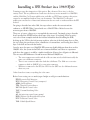
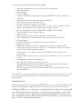
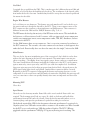
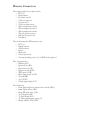
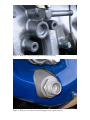
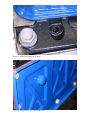
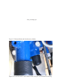
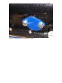
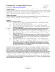
Adapting 3FE Induction to a
2F in a 1969 FJ40
by Jon M. Stewart
Installing a 3FE Stroker in a 1969 FJ40
Daunting was my first impression of this project. But, the more I dove into it, the less
anxiety I had. The two publications I used were the factory service manual for a 1989 FJ62,
and the 1988 New Car Features publication available as a PDF. In my opinion, this project
cannot be accomplished without those two documents. The 1988 New Car Features
publication contains lots of functional information that was used to understand how the EFI
worked.
I’m going to describe here what I did, the steps taken to make the conversion from
carburetor to 3FE EFI. What I started with was a 1986 2F. What I bolted on was the
necessary parts from a 1989 FJ62.
There are, of course, other ways to accomplish the same result. I’m simply going to describe
how I installed the 3FE EFI and resolved some of the issues. It’s nothing a little creativity
can’t solve. Some examples include the fuel line behind the head, disabling the EGR,
hooking up the VSV for the fuel pressure regulator, selection of the fuel pump, how to filter
the air, solving the speed sensor issue, elimination of vacuum lines, and routing those lines I
kept. I also had an issue with the brakes.
I need to note that parts on a 1988 FJ62 EFI system are slightly different than those used in
1989/90. Also, the system in the FJ80s are even more different and I have no experience
with those but suspect it would be a similar installation (I know the coil/ignitor is different).
The two major EFI differences I found between 1988 and 1989/90 are:
•
•
•
The water temperature switch and the cold start time switch, while functionally the
same, uses a different connector.
There is one connector under the dash that is different. The 1988 uses a two wire
connector, while in 1989/90 it’s a seven wire connector.
While not connected to the EFI, the VSVs for the 4WD are also different between
these two years.
Other than those items, everything else is the same.
Before I start tossing out too much jargon I might as well give some definitions.
EFI: Electronic Fuel Injection
ECU: Electronic Control Unit (computer)
AFM: Air Flow Meter
TPS: Throttle Position Sensor
ISC: Idle Speed Control valve
VSV: Vacuum Switching Valve
VCV:
AI: Air injection control (smog pump)
EGR : Exhaust Gas Recirculation system
PCV: Pollution Control Valve
VSS: Vehicle Speed Sensor
To do this conversion I harvested from a donor FJ62:
•
•
•
•
•
•
•
•
•
•
•
•
•
•
•
•
•
•
•
•
•
•
•
•
•
The head with thermostat housing, tubes, sensors, and switches.
Exhaust manifolds.
Exhaust flanges.
Ox sensor flanges.
Complete induction, including throttle body with TPS, ISC, along with all hoses,
and tubes.
AFM with air tube to throttle body and attached hoses.
The air box is optional, and I didn’t use it.
Fuel rail with injectors, regulator, and damper.
Fuel lines at the front and back of the valve cover that attach to the fuel rail at the
damper and the regulator. Don’t bend them getting the head off.
ECU from behind the glove box. 89661-60021 (89661-60020 in 1988)
Throttle pedal. I also got the hand throttle.
Throttle cable.
Main computer relay located under the airbox. 85915-60010
Circuit Open Relay located in the passenger side kick panel. 85910-14020
Coil with ignitor.
Distributor. There are no aftermarket alternatives at this time.
Engine wire harness.
Main harness that runs under the dash from the fuse block to under the hood
VSV for the fuel pressure regulator. It’s part of a 3-way block of VSVs on the driver’s
fender. I’ll discuss this in more detail later.
If installed in a smog equipped truck the AI and EGR systems will need to be
harvested too.
Heater distribution pipes that run on the passenger side of the valve cover attached
to head.
Fuel pump block off plate. I made my own.
All of the little things associated with the above.
The 1986 motor already had the 2F side cover with the indent for the large cap
distributor. This will not be provided by the FJ62 donor.
The 2F also needs to have flat-top pistions. Early dome top pistons will not work
with the 3FE head.
It’s a good idea to get as many of the hoses as possible. In some cases harvesting was easier if I
cut some hoses and replaced them later. I found that most of them are not that expensive
from the dealer.
Disabling Emissions
Since my motor went into a smog-exempt 1969 FJ40 I choose not to install the EGR and AI
systems. This significantly simplified the motor and kept the space under the hood tidy.
Disabling the EGR is one area where there are multiple solutions. Others have used threaded
caps and block off plates. My solution was to pound in expansion plugs (Figs. 1 & 2). There
were two I needed. One goes on the fitting on the exhaust manifold (.75”), and the other
goes on the plenum where the EGR valve lived (.829”/21mm). Both are a tight squeeze, but
they fit. This was a clean and cheap solution.
For the AI system the ports on the head need to be plugged. Rather than using brass NPT
plugs I choose to use the Toyota part. The 3FE head only has four cylinders attached to the
injection rail. The other two, used on 2F motors, are sealed with an allen-head plug. These
are available from Toyota, part number 90340-14001 (Fig. 3). I suspect BSPT (metric) plugs
would also work and would be cheaper than the dealer (about $2 each from McMaster-Carr).
Again, simple and clean.
Charcoal Canister
This was an interesting setup. On mini-trucks there is a vapor line from the tank that goes to
the canister. There is a second line that runs from the canister to the throttle body. On the
3FE, there is a VCV that sits between the line from the throttle body and the canister. This
was retained. I only made one minor change. One line from the VCV goes to the airbox.
Because the airbox was not used I just installed a small filter from a VSV on the port.
PCV
The 3FE uses different PCV plumbing than the 2F. The easiest solution was to keep the 3FE
connection from the PCV on the valve cover to the plenum. The PCV connects to the 2F
on the side cover. What I did was cut off the tube from the side cover and weld in a bolt
head to fill the hole. I probably could have cut it down further and made it flush with the
cover as the tube does recess a bit into the side cover. The bump looks OK (Fig. 4).
Fuel Pump and Delivery (draft)
For the 3FE EFI I needed a fuel pump that puts out 43 PSI. In the aftermarket, several 45 PSI
pumps are available. (Fig.5)
Bla, bla, bla. Still trying to figure this out.
Air Filter
At first I wanted to retain the FJ62 air box, but realized that without moving the battery it
wasn’t going to happen. Fortunately, many of the parts on the 3FE are similar to those on the
7M motor used in the Supra. I bought on Ebay an adaptor that allowed me to bolt up a cone
filter to the 3FE AFM. This was a simple solution. I am concerned about filtering and am
looking at a pre-filter to fit over the cone, and possibility a larger Amsoil cone filter which
might filter better. (Fig. 6)
The other thing I did was shorten the run from the AFM to the throttle body. The air tube
from the AFM to the throttle body consists of three pieces. Attached to the AFM is a bent
rubber hose with a fitting for the ISC. It actually contains a steel fitting to connect the larger
hose to the smaller hose running to the ISC. Attached to that is a steel pipe with a fitting for
the valve cover breather. Then between the steel pipe and the throttle body is another bent
rubber hose.
What I did was take the short metal connector for the ISC and weld it into the metal pipe so
there was a port for the breather and a port for the ISC (Fig. 8). I then bought a 3” silicone
coupling at Autozone to connect the AFM to the metal pipe. I found the silicone coupling
in the performance section at most auto-parts stores. The AFM and steel pipe are just
slightly larger than 3” so I used a heat gun to warm up the coupling so it would slip on easier.
Gas Pedal
I acquired the gas pedal from the FJ62. This is another part that’s different between 1988 and
1989/90, at least with how the hand throttle hooks up. The attachment of the throttle cable
from under the hood is the same. I modified my firewall to accept the new throttle pedal and
the mount for the cable.
Engine Wire Harness
As I said, there are two harnesses. This harness was used unmolested. I just hooked it up to
the sensors and ran it though the firewall to the ECU. There is one connector next to the
ECU connectors that connects to the main harness on 1989 harnesses. This connector is
different between the 1988 and the 1989/90 harnesses (Fig. 7a, b, c).
The EFI harness hooked up the majority of the EFI items on the motor. This included the
fuel injectors, cold start injector, both Ox sensors, cold start time switch, water temperature
switch, water temperature sensor, water temperature sender, TPS, ISC, distributor, and two
connectors for the ECU.
On the 1988 harness there are two connectors. One is a two wire connector located next to
the ECU connectors. The second is a five wire connector located next to the diagnostic box
under the hood. Functionally, these two have the same job as the single 7 wire used in 1989.
Main Harness
This was, by far, the most intimidating part of the conversion. I don’t think it can be done
without the wire diagram in the factory service manual. The main harness contains just
about everything … headlights, horn, turn signals, gauges, heater, and way too much more.
The items I needed from this harness included the connectors for the ECU, air flow meter,
ignitor, main relay, circuit open relay, and VSVs (see table for complete list). In addition
there were wires necessary for hooking up power from the fuse block, the speed sensor, the
4WD signal, brake light switch, and ground. I marked these connectors before I started.
Beginning at the ECU connector I unwrapped the harness and tracing the wires to each
component. It took several hours and I did make a few mistakes. Hopefully, this write-up will
save you some time as others can quickly identify what items are important and those that
are not.
Mounting ECU
Glove box.
Speed Sensor
I fretted over this for many months. Some folks said it wasn’t needed. Some said it was
required. The documentation I had was vague. So, while at the boneyard I pulled the
speedometer from an FJ62 and took it home. I then hooked up my multi-meter, set it to
continuity/beep, and spun the speedometer. It pulsed four times per revolution.
I had already acquired the VSS for the Autometer electronic speedometer. It consisted of a
16-pulse square wave VSS and a custom cable to connect to the transfer case. What I needed
for the ECU was a reed-switch type VSS that produced 4 pulses. The ECU VSS runs
piggyback with the speedometer VSS (Fig. 9). Again, my fretting was for nothing. The
company that provided both VSS’s and cable was Speedometer Service Co., Milwaukee, WI,
414/463-6660.
Fuel Pressure VSV
The fuel pressure VSV is part of a three-way block of VSVs. In order, from the front of the
truck, is the AI VSV, the EGR VSV, and the VSV closest to the firewall is for the fuel
pressure regulator. The EGR has its own connector, but the fuel pressure and the AI VSVs
are wired to the same connector (FJ80s use three separate connectors, the fuel pressure VSV
is brown).
What I did was cut off the connector and replace it with a Weather Pack connector, and
modified the harness to match. I then removed the VSV from the three-way mount and
made a bracket for it. It was relocated on the front side of the plenum close to the fuel
pressure regulator and the vacuum supply. (Fig. 10)
One note about the IA and EGR VSVs. Some feel that because they are controlled by the
ECU they are necessary and their absence will trigger the Check Engine Light (CEL). I’m
not convinced. These are switches, not sensors. They only receive power triggered by the
ECU and I don’t think the ECU has the ability to detect their presence, absence, or
malfunction.
Accessories
In my case I kept the 2F accessories. I also used the 2F water pump. The power steering
pump was retained on the driver side of the motor and the alternator was mounted on the
passenger side, both in the high position. To tighten the power steering belt I made an idler
pulley setup that mounted in the smog pump location.
Routing Coolent Lines
Bla, bla, bla.
Power Brakes
This was another area that caused me much grief. The induction on a 3FE takes up more
space than the 2F. I was having problems with fitting a brake booster under the hood with
the 2F and the clearance became worse with the 3FE plenum. I had already acquired a spacer
from Mark’s Off-Road to space the booster out from the clutch master, but the booster was
still in the way of the motor. The solution was to cut out the firewall with the mounts for the
brake and clutch masters and move it over three inches (Fig. 11). A section of firewall rib
was removed at the same time. I also needed to bend the pedals to the right.
The Little Stuff
There is a port on the 3FE thermostat housing, driver’s side, that isn’t used with the 2F
plumbing. I used part number 90339-16001 to block off this port (Fig. 13). There is also a
port on the 3FE heater plumbing that wasn’t used. It was blocked off using part number
90339-13009 (Fig. 13).
I went with an aftermarket temperature sensor. In hindsight I should have pulled the OEM
sensor and adapted the Autometer sensor. Instead I drilled and tapped the thermostat
housing and installed the sensor on the lower right side (Fig. 14).
When I acquired the parts from my donor FJ62 I couldn’t get to the block off plate for the
fuel pump. Using a gasket as a template I made my own out of 1/8” steel (Fig. 14). Of course
on subsequent trips I was able to acquire the factory plate.
Disclaimer
The intent of this article was to document how I installed 3FE induction on a 2F block in
my 1969 FJ40. I’ve described what I did, which may or may not work for others. Chances are
that others will find additional issues that will need to be addressed. There could also be
better solutions. In no way am I going to imply that what I did was necessarily the right or
best way. I am not a professional mechanic and my skills are very “shade tree” though not
quite “bubba.” If it’s decided to tackle this project it will be up to the installer to determine
that they have the necessary skills, knowledge, and tools to accomplish the job. Like I said,
this article is to be used in combination with the Factory Service Manual and the 1988 New
Car Features publication. The ability to read a wire diagram is required. I did not attempt to
give detailed step-by-step instructions on the installation. I put in a lot of work, research,
and spent a lot of money to make this conversion work. Why should I take out the challenge
or fun others should have?
Harness Connectors
The engine harness has connectors for:
• ECU (2)
• Main harness
• Fuel injectors (6)
• Cold start injector
• Ox sensors (2)
• Cold start time switch
• Water temperature switch
• Water temperature sensor
• Water temperature sender
• Throttle position sensor
• Idle speed control valve
• Distributor
The main harness has EFI connectors for:
• ECU (1)
• Engine harness
• Air flow meter
• Ignitor
• Main relay
• Circuit open relay
• Vacuum switching valves (3: AI, EGR, fuel regulator)
Plus, it has wires for:
• EFI Fuse (R-Y)
• Ignition Fuse (B-L)
• Speed sensor (G-B)
• Ignition switch (B-W)
• 4WD switch (Y-B)
• Brake light switch (G-W)
• Ground (BR)
• A\C (B-W)
• Check engine light (Y-G)
4th Connector:
• From: Ignition-Starter (neutral start switch) (B-R)
• From: Ignition Fuse (B-L)
• From: EFI main relay (Y-R)
• To: Tachometer (B)
• To: Fuel Pump (R-G)
• To: Water temperature gauge (G)
• Bridge: AFM to TPS (G-R)
2FE Rebuild Parts
Part
Need
Gasket, head
Gasket, intake/exhaust
Gasket, plenum
Gasket, throttle body
Gasket, ISC valve
PCV grommet
Washer, cyl head cover
Thermostat
Gasket, thermostat
Gasket, water outlet
Gasket, water outlet housing
O-ring #1, fuel injector
O-ring #2, fuel injector
Gasket, fuel pipe 2, regulator
Gasket, damper
Gasket, fuel pipe, damper
gasket, fuel pipe 3, cold start
Gasket, cold start
O-ring, distributor
Distributor cap
Distributor rotor
Spark plug wires
Gasket, exhaust pipe
Plug #1, rear head
Gasket, valve cover
Gasket, side cover
Gasket, timing cover
Gasket, front end plate
Gasket, oil pan
Gasket, water pump
Gasket, oil pump
Plug, expansion, cam
O-ring, oil cooler
Water pump, reman?
Seal, rear main
Seal, front main
Fuel pump gasket
Gasket, oil filter bracket
1
1
1
1
1
4
1
1
1
1
6
6
2
1
1
4
1
1
1
1
1
2
1
1
1
1
1
1
1
2
1
2
1
1
1
1
1
3FE
11115-61030
17172-61060
17176-61020
22271-61020
22278-42010
90480-18001
90210-13001
90916-03052
90430-43002
16341-61030
16343-61020
90301-07001
90301-19006
90430-08011
23232-41081
90430-12005
90430-08011
23293-74010
90099-14090
19101-61240
19102-61240
90919-21451
90917-06039
96411-45000
11213-61020
11496-61010
Assorted Part Numbers
•
•
•
•
•
1986 2F
EFI emblem on top of plenum: 11292-61010
Thermostat bypass port plug: 90339-16001
Rear heater port plug: 90339-13009
Air rail plugs on head: 90340-14001
OEM fuel pump block off plate (disco’d): 11495-61010
11253-60010
11328-61010
11312-61021
12151-61010
16271-60012
90430-15261
90311-48010
90301-21176
16100-61130
90311-99065
90311-45008
90923-05016
15691-61010
Figure 1. EGR port on plenum plugged with expansion plug.
Figure 2. EGR port on exhaust manifold plugged with expansion plug.
Figure 3. Allen head plugs on AI ports.
Figure 4. Plugged PCV port on 2F side cover.
Sorry, no image yet.
Figure 5. Rerouted fuel line behind head.
Figure 6. Intake from cone filter to
AFM.
7a. 5 wire connector on 1988.
7c. 7 wire connector on 1989.
7b. 2 wire connector on 1988.
Figure 8. Intake showing steel pipe with double ports, one for breather, the second for ISC.
Figure 9. Piggyback vehicle speed sensors. Top is the VSS for the Autometer speedometer.
Lower is the VSS for the ECU speed signal.
Figure 10. Fuel pressure regulator VSV mounted on plenum directly from vacuum to
regulator.
Sorry, no image yet
Figure 11. Relocated brake and clutch master cylinders.
Figure 12. Part 90339-16001 used to block off the extra port on the thermostat housing
Sorry, no image yet
Figure 13. Part 90339-13009 used to block off the extra heater port.
Figure 14. Location of aftermarket
temperature sensor.
Figure 15. Garage-made fuel pump block off plate.