1
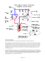
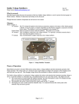
Troubleshooting Lucas Points Ignition Systems
Doug Lawson ([email protected])
Rev.02
July, 2006
What is Covered:
The following document discusses the operation of the basic “points type” ignition system. Included are steps
to troubleshoot the ignition system. This document presents a negative ground system only. Please read the
Theory of Operation section before attempting to troubleshoot your ignition system.
What is Not Covered:
Symptoms of ignition system failure are not presented. Ballasted ignition coil systems are briefly discussed
in the closing. Steps to troubleshoot the ballast ignitions are not presented here.
Glossary:
(Refer to the following schematic)
A:
B:
C:
D & E:
F:
G:
H:
Condenser. This is a capacitor wired in parallel to the points. It absorbs energy when the
points open to prevent their pitting and burning.
Points. The points act as a switch, connecting the coil’s (-) terminal to chassis ground.
Distributor Cam. This multi-lobed spline rotates at 1/2 engine speed. High spots on the cam
open and close the points
Coil. The coil operates as a transformer, boosting battery potential (on the primary or lowtension side “D”) to several thousand volts (on the secondary or high-tension side “E”).
Distributor Cap. The distributor cap serves as a distribution center. High-voltage developed
by the coil is delivered to the appropriate spark plug according to the position of the rotor “G”
inside the distributor cap.
Distributor Rotor. This is a moving contact attached to the top of the distributor cam. Highvoltage from the coil enters the center of the distributor cap and is routed along the rotor to its
tip. As the distributor cam rotates it moves the rotor inside the cap to align with contacts
inside the distributor cap.
Spark Plugs. The spark plugs are connected to the distributor cap by the spark plug wires.
High-voltage travels down these wires and passes through the center insulator of the spark
plug. Inside the combustion chamber, this energy jumps an air gap between the center
electrode and the shell of the spark plug. The spark plug shell is grounded when threaded
into the combustion chamber. High-voltage jumping this air gap produces a spark to ignite
the fuel air mixture in the combustion chamber.
Successfully troubleshooting engine problems comes with experience and familiarity with the theories of
operation for the fuel and ignition systems. Total ignition system failure results in the sudden and complete
shutdown of an engine. Poorly adjusted or worn ignition system components can result in engines that are
hard to start, misfire at speed, or suffer from poor drivability. Seemingly unrelated factors such as high
relative humidity or rain can exacerbate these problems. Fuel problems typically cause a slow and sputtering
shutdown of an engine or its inability to achieve full power or speed. Methodically testing the basic system
components while duplicating (where possible) the situations under which the problems occur will generally
result in the source of the problem being identified. There are not many parts to go wrong in a points system
so troubleshooting is a process of following the voltage through the circuit. If a spark is present and occurs at
the correct time the fuel system is suspect.
Page 1 of 7
Ignition System Schematic
Theory of Operation:
In the discussions that follow, all electrical polarity mentioned is for negative ground cars.
Points ignition systems consist of high- and low-tension circuits. The low-tension circuit operates at battery
voltage, the high-tension circuit provides the energy to produce a spark in the combustion chamber to ignite
the fuel/air mixture. The low-tension circuit includes the ignition switch, points, condenser, and coil while
the high-tension circuit includes the coil, distributor cap & rotor, spark plugs and spark plug wires. The lowand high-tension circuits meet inside the coil which acts as a transformer, stepping up battery potential to
several thousand volts.
When the ignition key is turned to the “on” or “run” position, battery voltage from the switch is supplied to
the coil’s (+) terminal. One side of the points inside the distributor are connected to the coil’s (-) terminal, the
other side is connected to chassis ground. When the points are closed (contacts touching), the points provide
a path to ground for electric current passing through the coil from the ignition switch. This current flows
through the primary or low-tension side of the coil.
Page 2 of 7
The low-tension side of the coil is composed of a small number of large diameter copper wire coils looped
around an iron core. The secondary or high-tension portion of the coil is composed of a large number of very
small copper wires wrapped around the same iron core as the primary coils. (This is analogous to a
transformer used with alternating current.)
While current is flowing through the low-tension circuit (points closed) a magnetic field is built up inside the
coil. There is NO significant voltage or current present on the high-tension circuit at this time. When the
current flowing through the low-tension circuit is broken or interrupted (points open), the magnetic field
collapses. This collapsing magnetic field produces a huge, short lived surge in voltage on the secondary or
high-tension circuit. This high-voltage exits the center terminal of the coil and travels to the distributor cap.
High-voltage can only develop if the power to the coil’s primary circuit is broken. This is the job of the
contact points (“B” in the figure above) which are opened and closed by the distributor cam (“C”) rotating at
1/2 engine speed. The points make and break the coil’s ground connection which allows the magnetic field to
grow and decay. The same decaying magnetic field that produces the spark at the spark plugs produces a
reverse voltage surge at the points. The condenser (“A”) is a capacitor wired parallel to the points. With an
inductive discharge type of ignition, which all point & coil ignitions are, the condenser serves two functions:
1) it provides a means to quickly discharge the coils magnetic field when the points open (which is essential
to generating the high spark voltage), and 2) the condenser reduces the point arcing which would otherwise
occur.
High voltage from the coil is delivered to the center contact of the distributor cap (“F”). It passes through the
cap to the center of the rotor (“G”) which is attached to the distributor cam. The distributor is designed so the
points will open each time the rotating rotor is aligned with one of the poles inside the distributor cap. This
allows the high-voltage from the coil to be routed uniquely to one spark plug at a time.
The Cycle:
With the ignition on, battery voltage is present on the coil’s (+) terminal. As the starter turns the engine, the
distributor cam begins turning. The cam opens the points causing the collapse of the magnetic field inside the
coil and a resulting voltage surge on the secondary side of the coil. The voltage surge on the secondary
windings is routed out of the coil to the center of the distributor cap, through the rotor, and to one of the poles
connected to a spark plug wire. The voltage travels to the spark plug where it produces a spark to ignite the
fuel/air mixture. The rotation of the cam continues, closing the points and re-charging the coil’s primary
windings. The next cam lobe opens the points again, repeating the process for the next cylinder.
Cautionary Notes:
Troubleshooting the ignition system must be performed with components energized and/or rotating. Keep
hair and loose clothes away from belts and pulleys. When handling high-tension wires, it is advised that they
be held with a thick, clean, dry rag to prevent possible shock.
Troubleshooting:
The steps presented below represent a process I follow when addressing an ignition problem. While this
routine works, it is not the only or necessarily the best method. As with all automotive work, exercise
common sense and work carefully. Secondary (spark) voltages routinely exceed 25,000 volts. In-spite-of
this, while the shock is painful it is usually not life threatening. Experiencing spark plug shock while working
on a running engine can lead to unforeseen consequences….
The following flowchart details steps to trace voltage and current through the ignition system. While a
volt/ohm meter is not necessary for many of these tests it is highly desirable to have one. UNDER NO
CIRCUMSTANCES should you attempt to measure the high-voltage on the secondary circuit.
If ignition failure is suspected, first inspect the obvious wear components.
Page 3 of 7
1) Examine the spark plug wires for any cracking, burning, or physical damage. ANY damage to a
spark plug wire can result in a spark shorting to ground before the voltage reaches the spark plug,
with a subsequent loss of power and rough running.
2) Examine the distributor cap for any tracks or cracks, excessive dirt or contamination. Any one of
these can short high-voltage from the coil to chassis ground or to the wrong plug wire. Any number
of rough running scenarios are possible.
3) Examine the points inside the distributor. Remove the distributor cap and use a flashlight to look at
the contact surfaces of the points. Use a small screwdriver to gently pry the points open while
looking at their surfaces. Any burning or excessive pitting indicates the need to burnish or replace the
points. Regardless, check and re-set the point gap as necessary before looking further.
Once it is felt that the mechanical components are in good order a series of electrical tests should be
performed to trace the path of current through the system. Begin with the steps in the following flowchart.
Where possible, the testing should be done under the conditions where failure occurred.
Figure 1 - Test Spark Plug With Clips.
Figure 2 - Shorting white/black wire to chassis ground.
(Note test plug and jumper wire to coil.)
Figure 3 - Checking coil primary resistance, low-tension wires
removed. (Here = 2.9 ohms)
Page 4 of 7
Figure 4 - Checking coil secondary resistance.
(Here = 9.79 k-ohms)
Test 1: Remove the ignition wire from the coil’s center terminal and hold 1/8”
from the entrance to the coil while an assistant cranks the engine.
Spark
Perform Test 7
Spark
Check cap, rotor, & points gap
No Spark
Use a jumper wire with clips to attach a test spark plug to the coil’s center
terminal. (See Figures 1 & 2)
Test 2: Remove the distributor cap, bump engine over until points are open. Turn
ignition on and watch test plug while repeatedly shorting points with a screwdriver
No Spark
Test 3: At the distributor, disconnect the white/black wire going to the coil. Turn
on the ignition and use a volt meter to check the voltage between the coil’s (+)
(white wire) terminal and chassis ground.
0v
12 v
Test 4: Turn on the ignition and repeatedly tap the white/black wire disconnected
in Test 3 to chassis ground while watching test plug.
No
Spark
Spark
Test 5: Check points. File/burnish and re-gap as necessary. Repeat Test 2
Spark
Check wiring to and from
ignition switch, check the
switch.
Turn off ignition, mark and
remove all wires from the coil.
Use a volt ohm meter to measure
the resistance of the coil’s
primary and secondary
windings. Primary should be
apx. 3 ohms, secondary should
be several thousand ohms.
Replace coil if measurements are
not correct. (See Figures 3 & 4)
Reconnect all wires and see if
engine will run.
No Spark
Won’t Run
Spark
Test 6: Remove condenser. Repeat Test 2
Test 7: Check/set ignition
timing. Check and/or replace
cap, rotor, spark plugs & plug
wires. Check fuel system.
No Spark
Examine ground connections inside distributor. See notes in following section.
Page 5 of 7
Replace condenser and repeat
Test 2
Reasons for Each Test:
Test 1. This test reveals whether or not there is spark produced by the ignition system. If there is spark it
will be important to check the timing, examine the cap, rotor, plugs and wires. If these do not reveal the
source of the problem, examine the fuel system.
Test 2. This test removes the cap, rotor, plugs and wires from the system and determines whether or not they
require attention.
Test 3. This test is performed to confirm that the coil is receiving power. If power is not on the coil’s (+)
terminal the ignition switch and its wiring should be examined.
Test 4. This test is performed to confirm that the coil can operate by itself apart from the points and
condenser. Failure to produce spark in Test 4 indicates a problem with the coil itself.
Test 5. This test is performed to confirm that the ignition points are in good condition and are properly
adjusted.
Test 6. This test is performed to confirm that the condenser is operating correctly. Failure to produce a
spark in Test 6 points towards a possible grounding problem inside the distributor or its associated wiring.
NOTE: Older points assemblies, particularly two-piece assemblies, utilize insulating washers and spacers
on the end of the point’s spring. If these are not in place and properly oriented the points will behave as if
they never open. This will prevent a spark from being produced.
Test 7. This test is performed if all other conditions indicate that the ignition system is functioning properly.
If spark is being produced correctly it must also occur at the correct time. Check and set the static ignition
timing. Failing this, the problem may lie elsewhere such as in the fuel system.
Notes on Ballast Ignitions:
There are many misconceptions about ballast ignitions and what they do. These notes are provided to
succinctly explain how they differ from the “standard” ignition systems presented above.
The ballast ignition system includes an external resistor (or resistor wire) in series with the voltage supply to
the coil’s (+) terminal. A “standard” coil will have an internal resistance close to 3 ohms on its primary
windings. The coil for a ballast ignition system will have a primary winding resistance between 1 and 2
ohms. The external ballast resistor (or resistor wire) will provide an additional 1.5 ohms of resistance.
Current flowing through the ballast resistor will create a voltage drop and thus lower the coil’s operating
voltage to something between 6- and 9-volts. Together, the ballast resistor and the internal resistance of the
coil limit the current flowing through the system.
The coil in a ballast ignition system will have a second connection on its (+) terminal. This second
connection is from the starter solenoid. During cranking the coil’s (+) terminal will receive full battery
voltage. This produces a MUCH hotter spark to help the engine start. Once the starter is released the coil
receives its power through the external resistor which drops its operating voltage.
The ballast coil can thus produce a hotter spark for starting. However, if the ballast coil is wired into the
ignition system WITHOUT the external resistor it will always operate at high voltage. The increased current
flow through the system and the higher spark voltages will cause premature failure of the points. It is
imperative therefore that the proper coil be installed in a car to maximize its ignition system.
When troubleshooting a ballasted ignition system the external resistor and its associated wiring must be added
to the components to examine.
Page 6 of 7
Determining Coil Type (Ballast vs. Standard):
It is important when buying a replacement coil that the correct type is selected for the vehicle’s ignition
system to achieve acceptable life and performance. Lucas ignition systems are often modified over the years
and determining what is required may not be as simple as referring to the owner’s or service manual.
Visual checks should be performed first. Some ballasted Lucas ignitions use a ballast resistor wire between
the ignition switch and the coil (+) terminal (frequently pink in color). It is also possible that an external
ballast resistor may be present instead of this wire. The ballast resistor will typically appear as a small
ceramic brick (with wires) mounted in the vicinity of the coil itself and connected between the ignition switch
and coil (+). Ballast ignition systems also have a wire between the coil (+) terminal and the starter solenoid.
If the car’s electrical system is totally unmolested these visual clues may be enough to identify the ignition
coil type installed/needed. However, this is often not the case.
To confirm the needed coil type it is best to make electrical measurements with a volt/ohm meter. Start by
performing the test shown previously in Figure 3 to measure the resistance across the coil’s low-tension
terminals with all the wires disconnected. Note this resistance value but do presume it correctly identifies the
coil needed. Perform the following additional test.
Re-attach the low-tension wires removed to perform the test shown in Figure 3. Connect the volt meter
between the coil’s (+) terminal and chassis ground. Temporarily fit a jumper wire between coil (-) and
chassis ground. The jumper wire will insure that current is flowing through the coil and any ballast
components during the test. It is necessary for current to be flowing to correctly measure the coil’s operating
voltage. With the meter and jumper wire connected, switch on the ignition and observe the meter. If the
meter shows battery voltage (nominally 12V), the system is non-ballasted and needs a standard ignition coil.
If the meter displays anything between 6V and 9V, a ballast-type ignition coil is required regardless of what
type of coil is currently on the vehicle. Standard ignition coils will have a primary resistance close to 3 ohms
while ballast ignition coils are typically between 1 ohms and 2 ohms.
Using a standard coil on a ballasted ignition system will result in low spark voltages potentially leading to
running problems. Using a ballast-type coil on a standard ignition system (without a ballast resistor) will
result in excessive current flowing through the ignition system. This will cause premature wear of the points
and potentially lead to reduced coil life.
Rev
02
Date
7/10/06
Changes
Changed text on the roll of the condenser on Dave Russell’s recommendation, Revised system schematic to
show A-Series firing order based on John Outhwaite’s observations, Added section on determining coil type.
Page 7 of 7