1
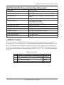
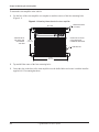
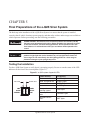
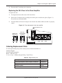
Electronic Siren System 8616033-01
Installation, Maintenance,
and Service Manual
255401A
REV. A 711
Printed in U.S.A.
blank page
Contents
Chapter 1 Safety Messages for Installers and Operators.......................................................5
Safety Messages to Installers of Federal Signal Sound/Light Systems.....................................................5
Safety Messages to Operators of Federal Signal Sound/Light Systems....................................................7
Chapter 2 An Overview of the e-Q2B 8616033-01 Siren System............................................9
LED Indicators...........................................................................................................................................9
Dimensions................................................................................................................................................9
Electrical Specifications and Operating Temperature.............................................................................. 11
e-Q2B Kit Contents................................................................................................................................. 11
Chapter 3 Wiring the e-Q2B Siren System.............................................................................12
Selecting the Mounting Location.............................................................................................................12
Reconnecting Speakers to the e-Q2B......................................................................................................13
Connecting the Control Head..................................................................................................................14
Reconnecting Power to the Model e-Q2B 8616033-01...........................................................................15
Reconnecting Power Leads to the e-Q2B 8616033-01......................................................................15
Preparing to Connect the Power Leads..............................................................................................17
Connecting the Power Leads to the Vehicle Battery..........................................................................18
Chapter 4 Mounting the Siren Amplifier.................................................................................19
Mounting the Siren Amplifier..................................................................................................................19
Chapter 5 Final Preparations of the e-Q2B Siren System.....................................................21
Testing the Installation.............................................................................................................................21
Distributing the Safety Message Card.....................................................................................................22
Applying the Siren Safety Labels in the Vehicle.....................................................................................22
Chapter 6 Safety Messages to Personnel Servicing Federal Signal Electronic Sirens.....23
Chapter 7 Servicing the e-Q2B Siren System........................................................................24
Servicing the Siren Amplifier..................................................................................................................24
Removing the Siren Amplifier...........................................................................................................24
Reinstalling the Siren Amplifier.........................................................................................................24
Replacing the 30 A Fuse in the Siren Amplifier.................................................................................25
Ordering Replacement Parts....................................................................................................................25
Getting Technical Support and Service...................................................................................................26
Returning a Product to Federal Signal.....................................................................................................26
e-Q2B 8616033-01 Siren System
3
Contents
Tables
Table 2.1 Kit contents.................................................................................................................................. 11
Table 9.1 Replacement parts.......................................................................................................................25
Figures
Figure 2.1 Model e-Q2B 8616033-01...........................................................................................................9
Figure 2.2 Model e-Q2B Series A and B......................................................................................................9
Figure 2.3 Dimensions of the siren amplifier..............................................................................................10
Figure 3.2 e-Q2B 200-watt speaker connections with two 100-watt speakers...........................................13
Figure 3.3 DB9 connection from control head to siren amplifier...............................................................14
Figure 3.4 Location of product label on Model e-Q2B Series A and B......................................................15
Figure 3.5 Order of power connections to e-Q2B 8616033-01...................................................................16
Figure 3.6 Connections for power, ground, and ignition............................................................................17
Figure 4.1 Mounting information for the siren amplifier............................................................................20
Figure 5.1 e-Q2B system diagnostic LEDs.................................................................................................21
Figure 5.2 Safety message card (left) and siren safety labels (right)..........................................................22
Figure 9.1 Fuse replacement in the siren amplifier ....................................................................................25
4
e-Q2B 8616033-02 Siren System
CHAPTER 1
Safety Messages for Installers and Operators
For your safety, read and understand this manual thoroughly before installing, operating, and servicing
the e-Q2B Siren Amplifier. The safety messages presented in this chapter and throughout the manual are
reminders to exercise extreme care at all times. In addition, read and understand the safety instructions to
installers (doc. no. 256A692), and keep it close at hand for reference.
To download copies of this manual, go to www.fedsig.com or call the Federal Signal Service Department
at 1-800-433-9132, 7 a.m. to 5 p.m., Monday through Friday (CT).
Safety Messages to Installers of Federal Signal
Sound/Light Systems
People’s lives depend on your proper installation and servicing of Federal Signal products. It is
important to read and follow all instructions shipped with this product. In addition, listed below are
some other important safety instructions and precautions you should follow:
Before Installation
Qualifications
• To properly install an electronic siren, you must have a good understanding of automotive electrical
procedures and systems, along with proficiency in the installation and service of safety warning
equipment. Always refer to the vehicle’s service manuals when performing equipment installations on
a vehicle.
Sound Hazards
• Your hearing and the hearing of others, in or close to your emergency vehicle, could be damaged
by loud sounds. This can occur from short exposures to very loud sounds, or from longer exposures
to moderately loud sounds. For hearing conservation guidance, refer to federal, state, or local
recommendations. OSHA Standard 1910.95 offers guidance on “Permissible Noise Exposure.”
• All effective sirens and horns produce loud sounds (120 dB) that may cause permanent hearing loss.
Always minimize your exposure to siren sound and wear hearing protection. Do not sound the siren
indoors or in enclosed areas where you and others will be exposed to the sound.
• Federal Signal siren amplifiers and speakers are designed to work together as a system. Combining
a siren and speaker from different manufacturers may reduce the warning effectiveness of the siren
system and may damage the components. You should verify or test your combination to make sure the
system works together properly and meets federal, state and local standards or guidelines.
e-Q2B 8616033-01 Siren System
5
Chapter 1: Safety Messages for Installers and Operators
During Installation
• Do NOT get metal shavings inside the product. Metal shavings in the product can cause the system
to fail. If drilling must be done near the unit, place an ESD approved cover over the unit to prevent
metal shavings from entering the unit. Inspect the unit after mounting to be sure there are no shavings
present in or near the unit.
• Do NOT connect this system to the vehicle battery until ALL other electrical connections are made,
mounting of all components is complete, and you have verified that no shorts exist. If wiring is shorted
to vehicle frame, high current conductors can cause hazardous sparks resulting in electrical fires or
flying molten metal.
• Be sure the siren amplifier and speaker(s) in your installation have compatible wattage ratings.
• In order for the electronic siren to function properly, the ground connection must be made to the
NEGATIVE battery terminal.
• Sound output will be severely reduced if any objects are in front of the speaker. If maximum sound
output is required for your application, you should ensure that the front of the speaker is clear of any
obstructions.
• Install the speaker(s) as far forward on the vehicle as possible, in a location which provides maximum
signaling effectiveness and minimizes the sound reaching the vehicle’s occupants. Refer to the
National Institute of Justice guide 500-00 for further information.
• Mounting the speakers behind the grille will reduce the sound output and warning effectiveness of the
siren system. Before mounting speakers behind the grille, make sure the vehicle operators are trained
and understand that this type of installation is less effective for warning others.
• Sound propagation and warning effectiveness will be severely reduced if the speaker is not facing
forward. Carefully follow the installation instructions and always install the speaker with the projector
facing forward.
• Do NOT install the speaker(s) or route the speaker wires where they may interfere with the operation
of air bag sensors.
• Installation of two speakers requires wiring speakers in phase.
• Never attempt to install aftermarket equipment, which connects to the vehicle wiring, without
reviewing a vehicle wiring diagram available from the vehicle manufacturer. Insure that your
installation will not affect vehicle operation and safety functions or circuits. Always check vehicle for
proper operation after installation.
• Do NOT install equipment or route wiring or cord in the deployment path of an air bag.
• If a vehicle seat is temporarily removed, verify with the vehicle manufacturer if the seat needs to be
recalibrated for proper air bag deployment.
• Locate the control head so the vehicle, controls, and microphone can be operated safely.
• When drilling into a vehicle structure, be sure that both sides of the surface are clear of anything that
could be damaged.
6
e-Q2B 8616033-01 Siren System
Chapter 1: Safety Messages for Installers and Operators
After Installation
• After installation, test the emergency warning system to ensure that it is operating properly.
• Test all vehicle functions, including horn operation, vehicle safety functions and vehicle light systems,
to ensure proper operation. Ensure that installation has not affected vehicle operation or changed any
vehicle safety function or circuit.
• After testing is complete, provide a copy of these instructions to the instructional staff and all
operating personnel.
• File these instructions in a safe place and refer to them when maintaining or reinstalling the product.
Failure to follow all safety precautions and instructions may result in property damage, serious
injury, or death.
RETAIN AND REFER TO THESE MESSAGES
Safety Messages to Operators of Federal Signal
Sound/Light Systems
People’s lives depend on your safe operation of Federal Signal products. It is important to read and follow
all instructions shipped with the products. In addition, listed below are some other important safety
instructions and precautions you should follow:
• Do not attempt to activate or de-activate the controls of the emergency warning system while driving
in a hazardous situation.
• Although your warning system is operating properly, it may not be completely effective. People
may not see, hear, or heed your warning signal. You must recognize this fact and continue driving
cautiously.
• Also, situations may occur which obstruct your warning signal when natural and man-made objects
are between your vehicle and others, such as raising your hood or trunk lid. If these situations occur,
be especially careful.
• All effective sirens and horns produce loud sounds that may cause, in certain situations, permanent
hearing loss. You and your passengers should consider taking appropriate safety precautions, such as
wearing hearing protection.
• In order to be an effective warning device, this product produces bright light that can be hazardous to
your eyesight when viewed at a close range. Do not stare directly into this lighting product at a close
range or permanent damage to your eyesight may occur.
• It is important that you fully understand how to safely operate this warning system before use.
• You should only operate your vehicle and its light/sound system in accordance with your
department’s Standard Operating Procedures.
e-Q2B 8616033-01 Siren System
7
Chapter 1: Safety Messages for Installers and Operators
• If a selected function does not perform properly or if any of the lamps remain illuminated when the
control is off, disconnect the power connector from the control unit and contact the nearest service
center.
• At the start of your shift, you should ensure that the entire warning light system and the siren system
is securely attached and operating properly.
• Suction cup mounting is for temporary applications only. The unit should be removed from the
window and stored securely when not in use. Temperature changes and sunlight can cause suction
cups to lose holding power. Periodically check the unit to be sure the suction cups have a firm grip
on the mounting surface. An improperly secured light could fall off of the vehicle causing injury and
damage.
• The holding power of magnetic mounting systems is dependent upon surface finish, surface flatness,
and thickness of the steel mounting surface. Therefore, to promote proper magnetic mounting:
✓ Mounting surface and magnets must be kept clean, dry, and free of foreign particles that
prevent good surface contact.
✓ Ensure that mounting surface is flat.
✓ A magnet mounting system should not be used on vehicles with vinyl tops.
✓ To prevent sliding of light assembly on mounting surface, quick acceleration and hard stops
should be avoided.
Failure to follow these precautions may result in property damage, serious injury, or death.
8
e-Q2B 8616033-01 Siren System
CHAPTER 2
An Overview of the e-Q2B 8616033-01 Siren System
Your new e-Q2B siren amplifier may look different, but it incorporates the latest solid state designs for
superior reliability and sound quality. The Model e-Q2B 8616033-01 (Figure 2.1) is a 200-watt, Class D
audio amplifier, which replaces Series A and B of the Model e-Q2B (Figure 2.2). The siren operates on a
12-volt, negative-ground electrical system. The siren circuits are protected by a replaceable 30 A fuse that
protrudes from the siren housing.
Figure 2.1 Model e-Q2B 8616033-01
Figure 2.2 Model e-Q2B Series A and B
LED Indicators
Green LEDs on the side of the siren amplifier indicate when power is supplied to the amplifier, when
output is available, and when a load is connected. Red LEDs indicate a speaker short or thermal overload.
Dimensions
See Figure 2.3 on page 10.
Height with cover
3.98 in (10.11 cm)
Width
7.66 in (19.46 cm)
Length
10.41 in (26.44 cm)
Net Weight
6.40 lb (2.91 kg)
e-Q2B 8616033-01 Siren System
9
Chapter 2: An Overview of the e-Q2B Siren System
Figure 2.3 Dimensions of the siren amplifier
TOP VIEW
7.66 in
(19.46 cm)
6.91 in
(17.55 cm)
9.28 in
(23.57 cm)
10.41 in
(26.44 cm)
SIDE VIEW
AIR VENTS ARE
LOCATED ON THIS SIDE
COOLING FAN IS LOCATED
ON THIS SIDE
3.91 in
(17.55 cm)
8.19 in
(23.57 cm)
10
e-Q2B 8616033-01 Siren System
Chapter 2: An Overview of the e-Q2B Siren System
Electrical Specifications and Operating Temperature
Input Voltage
11 Vdc to 16 Vdc
Polarity
Negative ground only
Standby Current
Less than 0.5 A
Operating Current
20 A (nominal) (13.6 V battery, 5.5-ohm load at high
power)
Frequency Range
725 to 1600 Hz
Nominal Cycle Rate
Wail: 12 cycles per minute
Yelp: 180 cycles per minute
Priority: 370 cycles per minute
Nominal Voltage Output
33 Vrms (siren tones)
Audio Response
300 Hz to 3 000 Hz ± 3 dB
Audio Power
200 W in PA Mode (typical with 1.4 V peak-to-peak input)
Harmonic Distortion
Less than 10 percent from 5 to 200 W
Input Impedance (PA)
4 000 ohms (nominal)
Siren Tone Compliances
SAE J1849 JUL89
Operating Temperature Range
–40 °C to +65 °C
e-Q2B Kit Contents
Table 2.1 lists the parts included with the e-Q2B Siren System. After unpacking the kit, examine it for
damage that may have occurred in transit. If the product has been damaged, file a claim immediately with
the carrier stating the extent of damage. Carefully check all envelopes, shipping labels, and tags before
removing or destroying them. Ensure all parts in the packing list are included in the shipment. If any parts
are missing, call Federal Signal Customer Support at 1-800-264-3578, 7 a.m. to 5 p.m., Monday through
Friday, CT.
Table 2.1 Kit contents
Qty.
Description
Part Number
1
e-Q2B Siren Amplifier, 200 W, Legacy Connection
8616033-01
1
Connector, 3-Position, Power
140535
1
Card, Safety Instructions
256B691
1
Label, Warning, Siren/Speaker
1612339
e-Q2B 8616033-01 Siren System
11
CHAPTER 3
Wiring the e-Q2B Siren System
Before permanently mounting the e-Q2B Siren System, plan all wire routings and select the mounting
locations for the siren amplifier. Also read and understand all instructions included with related equipment
before installing it.
Selecting the Mounting Location
Suggested mounting locations are under the front seat, in a vehicle compartment, or in the trunk under the
rear deck near the rear-seat speakers. After completing the wiring described in this chapter, refer to the
instructions for mounting the siren amplifier in Chapter 4 on page 19.
Air bag DEPLOYMENT—Do not install equipment or route wiring in the deployment
path of an air bag. Failure to observe this warning will reduce the effectiveness of
the air bag or potentially dislodge the equipment, causing serious injury or death.
SEAT REMOVAL PRECAUTION—If a vehicle seat is temporarily removed, verify
with the vehicle manufacturer if the seat needs to be recalibrated for proper air bag
deployment.
UNIT REQUIRES AIR FLOW—The siren amplifier is cooled by an internal fan. Do
not install it in areas where the air flow is restricted. Do not mount the unit near a
heater duct or under the hood.
UNIT IS NOT WATERPROOF—The housing of the e-Q2B siren amplifier is NOT
waterproof. The module must be mounted in a location that is sheltered from falling
rain, snow, standing water, etc.
Wiring connectors are located on the siren amplifier. Ground, ignition, and power connections are located
on the three-position, pluggable, terminal block. To maintain the reliability of the siren amplifier, do not
block the air vents or the fan (Figure 2.1 on page 9).
12
e-Q2B 8616033-01 Siren System
Chapter 3: Wiring the e-Q2B Siren System
Reconnecting Speakers to the e-Q2B
SOUND HAZARD—All effective sirens and horns produce loud sounds produce
loud sounds (120 dB) that may cause permanent hearing loss. Always minimize
your exposure to siren and horn sounds and wear hearing protection. Do not sound
the siren or horn indoors or in enclosed areas where you and others will be exposed
to the sound.
SPEAKER CONNECTIONS—For proper operation and performance, always
connect the speakers in parallel and in phase.
The Model e-Q2B 8616033-01 operates one 200-watt speaker or two 100-watt speakers with an
impedance of 11 ohms.
To connect the two 11-ohm, 100-watt speakers to the Model e-Q2B siren amplifier:
1. Reconnect the speaker output connector (Figure 3.2).
2. To prevent fretting or disconnection, tighten the two screws on the four-position speaker connector.
Figure 3.2 e-Q2B 200-watt speaker connections with two 100-watt speakers
MODEL eQ2B 8616033-01
1. LOOSEN SCREW.
2. INSERT STRIPPED
WIRE IN CONNECTOR.
3. TIGHTEN SCREW.
+ RED
+ WHT
-POWER
-OUTPUT
-LOAD
LIMITSHORTTHERMAL-
SPEAKER B
− GRN
− BLK
SPEAKER OUTPUT
B
SPEAKER A
A
TWO BP100 SPEAKERS,
11 OHM, 100 WATT EACH
B
SPEAKER B
TWO ES100 SPEAKERS,
11 OHM, 100 WATT EACH
B
SPEAKER A
A
A
FOUR-POSITION
SPEAKER CONNECTOR
P/N 140417-04
S
INSULATION STRIPPED
0.25 in (0.635 mm)
e-Q2B 8616033-01 Siren System
P
S
E
S
A
P
K
E
R
S
P
E
A
B
P
K
E
A
E
(−
R
)
A
E
K
E
(−
R
)
A
K
B
E
(+
R
)
A
(+
)
13
Chapter 3: Wiring the e-Q2B Siren System
Connecting the Control Head
To connect the control head to the siren amplifier:
1. Plug the DB9 cable connector from the control head into the legacy connector in the upper left corner
of the siren amplifier (Figure 3.3)
2. Plug the other end of the cable into the connector on the back of the control head.
3. Hand-tighten the thumb screws on the DB9 cable-connector to secure it to the legacy connector.
4. To provide strain relief, secure the cables with installer-supplied clamps and hold-downs.
Figure 3.3 DB9 connection from control head to siren amplifier
DB9 CONNECTOR
FROM CONTROL HEAD
A
LIMITSHORTTHERMAL-
30 AMP
FUSE
14
RED WHT/RED
(+BAT) (IGN)
BLK
(-BAT)
e-Q2B 8616033-01 Siren System
-POWER
-OUTPUT
-LOAD
+ RED
+ WHT
− GRN
− BLK
SPEAKER OUTPUT
Chapter 3: Wiring the e-Q2B Siren System
Reconnecting Power to the Model e-Q2B 8616033-01
BATTERY EXPLOSION—To avoid a battery explosion, always disconnect the
negative battery cable first and reconnect it last. Avoid causing a spark when
connecting near or to the battery. The gases produced by a battery can cause a
battery explosion that could result in vehicle damage and serious injury.
HIGH CURRENT ARCING—Do not connect this system to the vehicle battery until
ALL other electrical connections are made and you have verified that no shorts
exist. High current conductors can cause hazardous sparks or burning wire
resulting in electrical fires.
Taking the preparatory steps in this chapter before mounting and wiring the siren amplifier to a vehicle
will help ensure that your installation is fast, easy, and error free. You will be reusing the power and
ignition cables from your old e-Q2B siren amplifier.
To avoid damage to your new e-Q2B siren system, disconnect the siren amplifier power (+BAT) and
ground (–BAT) cables from the battery.
Reconnecting Power Leads e-Q2B 8616033-01 from the Series A
If your old e-Q2B siren amplifier is a Series A (Figure 3.4), you must cut the power leads from the
old terminal to connect them to your replacement e-Q2B as described in this section.
Figure 3.4 Location of product label on Model e-Q2B Series A and B
FEDERAL SIGNAL
CORPORATION
UNIVERSITY PARK, IL U.S.A.
SERIES:
A
MODEL:
VOLTS:
EQ2B
12 VDC
To re-terminate the power leads to the e-Q2B 8616033-01 from the Series A:
1.
To dismount the old siren amplifier, and remove and retain the hardware securing it to the
mounting location. Remove it from the vehicle.
e-Q2B 8616033-01 Siren System
15
Chapter 3: Wiring the e-Q2B Siren System
2. Press the tab on the 3-position power terminal to release it and unplug it from the siren
amplifier.
3.
Cut the three leads close to the Series A power terminals and strip 1/4 inch from the end of
each lead.
4.
Note the order of the legends below the power terminals on the e-Q2B 86166033-01:
RED (+BAT), WHT/RED (IGN), and BLK (–BAT) (Figure 3.6 on page 17).
REVERSE POLARITY/MISWIRING—Reverse polarity may damage the
siren amplifier. To avoid damage to the siren/amplifier, ensure that the
battery voltage is the same as voltage as the rating of the light and that
the correct polarity is observed.
5.
Loosen the screws on the 3-position power connector and insert the stripped ends of the leads
into the terminals in the same order as shown in the legends (Figure 3.5). Tighten the screws.
Figure 3.5 Order of power connections to e-Q2B 8616033-01
e-Q2B SERIES A
TO RELEASE CONNECTOR,
PRESS DOWN ON TAB
BLA
WH
CK
RE
T/R
D
ED
e-Q2B SERIES B or 8616033-01
BLA
CK
WH
T
RE /RED
D
TO BATTERY GROUND (−BAT)
2A
TO IGNITION
30A
TO 12 VDC (+BAT)
16
e-Q2B 8616033-01 Siren System
Chapter 3: Wiring the e-Q2B Siren System
6.
Insert the 3-position power terminal into the power connector on the e-Q2B 8616300-01
(Figure 3.6).
7.
To prevent fretting or disconnection, tighten the two side-screws on the connector.
Figure 3.6 Connections for power, ground, and ignition
1. LOOSEN SCREW.
2. INSERT STRIPPED
WIRE IN CONNECTOR.
3. TIGHTEN SCREW.
30 AMP
FUSE
RED WHT/RED BLK
(+BAT) (IGN)
(−BAT)
TO RELEASE THE CONNECTOR
FOR REMOVAL, PUSH UP
ON THE ENDS OF THE ORANGE
TABS, THEN PULL THEM FORWARD.
BLA
CK
WH
T
RE /RED
D
TO −GROUND
2A
TO IGNITION
30A
TO 12 VDC (+BAT)
Preparing to Connect the Power Leads
Before connecting the amplifier/relay module to the battery, ensure that your final installation goes
smoothly by taking these preparatory steps:
1.
Visually check all connections and wiring to ensure that all connections are correct and secure.
2.
Ensure that there are no loose strands or other bare wires that may cause a short circuit.
Also, all wires must be protected from any sharp edges that could eventually cut through the
insulation.
3.
Verify that are other electrical connections are completed and that no shorts exit.
4.
Use an ohmmeter to verify that a short circuit does not exist between the positive (+) and
negative (–) battery cable leads. Also, there must be no short circuits between the positive
wires and the vehicle chassis.
5.
Insulate spliced leads with twist-on wire connectors. Fold and seal unused leads. Use wire ties
and hold-downs for strain relief.
e-Q2B 8616033-01 Siren System
17
Chapter 3: Wiring the e-Q2B Siren System
Connecting the Power Leads to the Vehicle Battery
The installer-supplied red (positive) and black (negative ground) power leads from the siren
amplifier to the vehicle battery should be as short and direct as possible.
18
1.
Connect the 10 AWG red positive lead (+) to a positive power source capable of supplying
40 amperes. Install a user-supplied 30-ampere fuse (minimum) at the source. The e-Q2B is
internally fused at 30 amperes (Figure 9.1 on page 25).
2.
Connect the 10 AWG negative (–) black lead directly to the negative battery terminal.
3.
Connect the 12 AWG white lead with the red stripe to a switched circuit that is hot, or active,
in the ON and START position of the vehicle ignition system. Install a user-supplied 2-ampere
fuse at the source.
4.
To prevent fretting or disconnection, tighten the screws on the connector.
e-Q2B 8616033-01 Siren System
CHAPTER 4
Mounting the Siren Amplifier
The next step in the installation after wiring and connecting the e-Q2B Siren System is to permanently
mount the siren amplifier and control head in the vehicle. Verify that the mounting locations you selected
earlier are safe for installing these components. Before installing the siren amplifier and control head, note
the following precautions.
Air bag DEPLOYMENT—Do not install equipment or route wiring in the deployment
path of an air bag. Failure to observe this warning will reduce the effectiveness of
the air bag or potentially dislodge the equipment, causing serious injury or death.
SEAT REMOVAL PRECAUTION—If a vehicle seat is temporarily removed, verify
with the vehicle manufacturer if the seat needs to be recalibrated for proper air bag
deployment.
UNIT REQUIRES UNRESTRICTED AIR FLOW—The siren amplifier is cooled by an
internal fan. Do not install it in areas where the air flow is restricted. Do not mount
the unit near a heater duct or under the hood.
UNIT IS NOT WATERPROOF—The housing of the siren amplifier is NOT waterproof.
The module must be mounted in a location that is sheltered from falling rain, snow,
standing water, etc.
DRILLING PRECAUTIONS—When drilling holes, check the area you are drilling into
to be sure you do not damage vehicle components while drilling. All drilled holes
should be de-burred and all sharp edges should be smoothed. All wire routings
going through drilled holes should be protected by a grommet or convolute/split
loom tubing.
Mounting the Siren Amplifier
Installer-supplied #10-32 mounting hardware is required to mount the siren amplifier.
Tools needed:
✔ #18 tap drill for steel and iron
✔ Phillips screwdriver
✔ Pencil or felt-tip pen for marking drill locations
e-Q2B 8616033-01 Siren System
19
Chapter 4: Mounting the Siren Amplifier
To mount the siren amplifier in the vehicle:
1. Use the base of the siren amplifier as a template to mark the centers of the four mounting holes
(Figure 4.1).
Figure 4.1 Mounting information for the siren amplifier
TOP VIEW
THREE SETS OF
AIR VENTS ARE
LOCATED ON
THIS SIDE
MOUNTING SLOTS
(4 PLACES)
INSTALLER-SUPPLIED
#10-32 MOUNTING
HARDWARE REQUIRED
6.91 in
(17.55 cm)
COOLING FAN
9.28 in
(23.57 cm)
2. Tap and drill the center of the four mounting holes.
3. Center the slots in the base of the siren amplifier over the drilled holes and secure it with the installersupplied #10-32 mounting hardware.
20
e-Q2B 8616033-01 Siren System
Chapter 5
Final Preparations of the e-Q2B Siren System
The final step in the installation of the e-Q2B Siren System is to ensure that the system is installed
correctly, that all vehicle functions operate properly, and that safety stickers and messages are available to
vehicle operators. Before proceeding, note the following precautions.
SOUND HAZARD—All effective sirens and horns produce loud sounds (120 dB)
that may cause permanent hearing loss. Always minimize your exposure to sound
of the siren and horn, and wear hearing protection. Do not sound the siren and
horn indoors or in enclosed areas where you and others will be exposed to the
sound.
LIGHT HAZARD—To be an effective warning device, an emergency warning system
produces bright light that can be hazardous to your eyesight when viewed at a
close range. Do not stare directly into this lighting product at a close range or
permanent damage to your eyesight may occur.
Testing the Installation
Test the e-Q2B Siren System to verify that it is operating properly. Be sure to note the status of the LED
indicators on the front of the siren amplifier (Figure 5.1).
Figure 5.1 e-Q2B system diagnostic LEDs
RED LEDS
GREEN LEDS
System Activity
LED Activity
Power on
No LEDs light
Power and ignition on
POWER lights
OUTPUT lights
SHORT lights
Siren active
Short circuit
LIMITSHORTTHERMAL-
-POWER
-OUTPUT
-LOAD
Siren speakers are
receiving current
LOAD lights
Siren amplifier overheats
THERMAL lights
30-ampere fuse is
intact
LIMIT lights
e-Q2B 8616033-01 Siren System
21
Chapter 5: Final Siren System Preparation
In addition, test all vehicle functions, including horn operation, vehicle safety functions, and vehicle
lighting systems for proper operation. Ensure that the installation has not affected the vehicle operation
or changed any vehicle safety functions or circuits. Do not test the sound and light system of the vehicle
while driving. Operating the vehicle warning system may pose a hazard to the operator and other drivers
if the system does not function as expected. Test the vehicle only in a controlled environment. After
testing is complete, provide a copy of this manual to the instructional staff and all operating personnel.
Distributing the Safety Message Card
Give the operator of the E-Q2B System the card entitled “Safety Message to Operators of Federal Signal
Light/Sound Systems” (part no. 256B691) (Figure 5.2). The operator must read and understand the safety
instructions and keep the card in the vehicle for reference.
Applying the Siren Safety Labels in the Vehicle
The e-Q2B Siren System kit includes a sheet of two labels with siren safety messages (part no. 1612339)
(Figure 5.2). These labels must be installed in the vehicle in which the system is installed. Place these
labels in areas that are clearly visible to operators and passengers. Do not adhere the labels to locations
that would impair the driver’s ability to operate the vehicle. Never install the labels in areas where air
bags may deploy.
Figure 5.2 Safety message card (left) and siren safety labels (right)
Chapter 6
Safety Messages to Personnel Servicing Federal Signal
Electronic Sirens
The people’s lives depend on your proper servicing of Federal Signal products. It is important to read
and follow all instructions shipped with the products. |In addition, listed below are some other safety
instructions and precautions you should follow:
• Read and understand all instructions in this manual before servicing the electronic siren or control head.
• To properly service an electronic siren or control head, you must have a good understanding of
automotive electrical procedures and systems, along with proficiency in the installation and service of
safety warning equipment. Always refer to the vehicle service manuals when performing service on a
vehicle.
• Electronic repairs must be performed by a qualified and competent electronics technician.
• Your hearing and the hearing of others, in or close to your emergency vehicle, could be damaged
by loud sounds. This can occur from short exposures to very loud sounds or from longer exposures
to moderately loud sounds. For hearing conservation guidance, refer to federal, state, or local
recommendations. OSHA Standard 1910.95 offers guidance on “Permissible Noise Exposure.”
• All effective sirens and horns produce loud sounds (120 dB) that may cause permanent hearing loss.
Always minimize your exposure to siren sound and wear hearing protection. Do not sound the siren
indoors or in enclosed areas where you and others will be exposed to the sound.
• Do NOT connect this system to the positive terminal of the battery until servicing is complete and you
have verified that there are no short circuits to ground.
• For the electronic siren to function properly, the ground connection must be made to the NEGATIVE
battery terminal.
• After repair, test the electronic siren and speaker system to ensure that it is operating properly.
• Federal Signal siren amplifiers and speakers are designed to work together as a system. Combining
a siren and speaker from different manufacturers may reduce the warning effectiveness of the siren
system and may damage the components. You should verify or test your combination to make sure the
system works together properly and meets both federal, state and local standards or guidelines.
Failure to follow all safety precautions and instructions may result in property damage, serious injury,
or death.
e-Q2B 8616033-01 Siren System
23
Chapter 7
Servicing the e-Q2B Siren System
Federal Signal recommends that the e-Q2B siren amplifier and control head be returned to your local
distributor or to Federal Signal for service. External components, such as cabling and the 30-ampere fuse,
are available as replacement parts (see Table 9.1 on page 25). With the exception of the selector knob and
the PA volume knob on the control head, there are no other user-serviceable parts within the control head
or the siren amplifier. After servicing the e-Q2B Siren System, test it to ensure that it is operating properly.
See “Chapter 5 Final Preparations of the e-Q2B Siren System” on page 21 for more information.
Servicing the Siren Amplifier
Servicing the siren amplifier includes replacing damaged cables or external wiring and the 30-ampere
fuse. It also includes removing and reinstalling the siren amplifier when necessary. For information on
ordering replacement parts from Federal Signal, see page 25.
Tools needed:
✔ 16" nut driver
✔ Flat-head screwdriver
✔ Small needle-nose pliers (for fuse replacement)
Removing the Siren Amplifier
To remove the siren amplifier for service or replacement:
1.
Remove and retain the installer-supplied #10-32 hardware.
2.
Disconnect the DB9 cable and speaker leads from the siren amplifier.
3.
Loosen the two strain-relief screws securing the power connector and unplug it.
Reinstalling the Siren Amplifier
To reinstall the siren amplifier in the vehicle:
24
1.
Test the siren system to ensure that it is operating properly.
2.
Reinstall the siren amplifier with the installer-supplied #10-32 hardware.
3.
Reconnect the DB9 connector and speaker leads from the siren amplifier.
e-Q2B 8616033-01 Siren System
Chapter 7: Servicing the e-Q2B Siren System
4.
Reconnect the 3-position power connector.
Replacing the 30 A Fuse in the Siren Amplifier
To replace the fuse:
1.
Investigate and correct the cause of the fuse failure.
2.
Remove the 30-ampere fuse by pulling it out with a pair of needle-nose pliers (Figure 9.1).
Be careful not to bend the blades.
3.
Insert the blades of the new 30-ampere fuse into the fuse holder. Make sure that it is properly
seated.
Figure 9.1 Fuse replacement in the siren amplifier
GOOD FUSE:
WIRE INTACT
BAD FUSE:
WIRE BURNED
THROUGH
30
LOCATION OF FUSE
30 AMP
FUSE
RED WHT/RED BLK
(+BAT) (IGN)
(−BAT)
Ordering Replacement Parts
To order replacement parts, please contact your local dealer/distributor or:
Customer Support
Federal Signal Corporation
Phone: 1-800-264-3578
(7 a.m. to 5 p.m., Monday through Friday, Central Time)
Table 9.1 Replacement parts
Description
Part Number
e-Q2B Siren Amplifier, 200 W, Legacy Connection
8616033-01
Fuse, 30 A
148A142-08
Connector, Power
140535
Connector, Speaker
140417-04
e-Q2B 8616033-01 Siren System
25
Chapter 7: Servicing the e-Q2B Siren System
Getting Technical Support and Service
Federal Signal Corporation will service your equipment or provide technical assistance with any problems
that cannot be handled locally. Any product returned to Federal Signal for service, inspection, or repair
must be accompanied by a Return Material Authorization number. The RMA number can be obtained
from your local distributor or Federal Signal. Please provide a brief explanation of the service requested
or the nature of the malfunction. Contact your local dealer/distributor for replacement parts availability or
contact the Federal Signal Service Department (7 a.m. to 5 p.m., Monday through Friday, CT) at:
Service Department
Federal Signal Corporation
2645 Federal Signal Drive
University Park, IL 60484-3167
800-433-9132
800-343-9706 (fax)
www.fedsig.com
Returning a Product to Federal Signal
Before returning a product to Federal Signal, call 800-264-3578, 800-433-9132, or 800-824-0254 to
obtain a Returned Merchandise Authorization number (RMA number). To expedite the process please be
prepared with the following information:
• Your Federal Signal customer or account number.
• The purchase order number under which the items were purchased.
• The shipping method.
• The model or part number of the product being returned.
• The quantity of products being returned.
• Drop ship information as needed.
• Any estimate required.
When you receive your RMA Number:
• Write the RMA number on the outside of the box of returned items.
• Reference the RMA number on your paperwork inside of the box.
• Write the RMA number down, so that you can easily check on status of the returned equipment.
Send all material with the issued RMA Number to:
Federal Signal Corporation
2645 Federal Signal Drive
University Park, IL 60484-3167
Attn: Service Department
RMA: #__________
26
e-Q2B 8616033-01 Siren System
blank page
2645 Federal Signal Drive, University Park, IL 60484-3167
Tel.: (800) 264-3578 • Fax: (800) 682-8022
www.fedsig.com
© 2011 Federal Signal Corporation