1
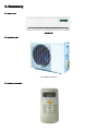
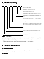
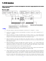
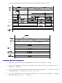
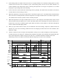
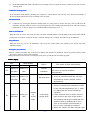
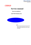
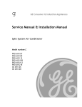
Service manual for Split Wall-Mounted Type Room air conditioner
Applied to: R410a
ACS-HR09LED R410A
NOTE:
Be sure to read the manual firstly before servicing the units。Please contacts
with your service center at any time if meet problem。
- 1 -
Contents
1、Summary…………………………………………………………………………………………………………03
2、Model explaining……………………………………………………………………………………………04
3、Installation ………………………………………………………………………………………………………05
4、Exploded view and part list………………………………………………………………………20
5、Operation principle………………………………………………………………………………………22
6、Parameter …………………………………………………………………………………………………………42
7、PCB function…………………………………………………………………………......47
8、Troubleshooting…………………………………………………………………………… 58
- 2 -
1. Summary
1.1 indoor unit
Model 81
1.2 outdoor unit
ACS-HR09LED R410A
1.3 remote controller
- 3 -
Model explaining
2、Model
c
Improve an ordinal number
Divide the body outdoors box a body code
External appearance characteristic code
Separately the body indoor machine(or whole type) style code
Separately the body pit code inside the indoor machine(or whole
ty p e)
Code of refrigerant type:no code - R 2 2 ;C-R4 0 7 c、A-R4 1 0 a
Power type:1:1 1 5 v/6 0 H z 2:2 2 0 V/6 0 H z ;3:2 2 0 -2 4 0 V/
5 0 H z ;4:240V/5 0 H z ;
Main function code: c-Cold breeze type;H-Hot pump type;A-H ot
pump the type take assistance electricity to heat;E-The electricity
heat
Capacity code: x1 0 0 0W
Structure form code
Special craft code:Q-Deal with contact quickly;S-Soft start;dOutside tube in addition to frost
The weather type code(T1 type code abridge)
"C" CHIGO brand
Model :CS-25C3A-V85AY1
T1 climate type,wall split type air conditioner, cooling capacity is 2500W , power is 220V ~
/50Hz/1PH,refrigeration is R410A,the kernel of indoor unit is fresh 98,the pattern no. is 85,first time
design, outdoor unit is 1HP of 2003 year。
Indoor unit modle is:CS-25C3A-V85A,outdoor unit model is:CS-25C3A-Y1。
3. Attention of installation
3.1 Safety Precaution
■To prevent injury to the user or other people and property damage, the following instructions must be followed.
■Incorrect operation due to ignoring instruction will cause harm or damage.
■Before service unit, be sure to read this service manual at first.
3.2 Warning
- 4 -
﹥Installation<
■Do not use a defective or underrated circuit breaker. Use this appliance on a dedicated circuit.
There is risk of fire or electric shock.
■For electrical work, contact the dealer, seller, a qualified electrician, or an Authorized service center.
Do not disassemble or repair the product, there is risk of fire or electric shock.
■Always ground the product.
There is risk of fire or electric shock.
■Install the panel and the cover of control box securely.
There is risk of fire of electric shock.
■Always install a dedicated circuit and breaker.
Improper wiring or installation may cause fore or electric shock.
■
Use the correctly rated breaker of fuse.
There is risk of fire or electric shock.
■Do not modify or extend the power cable.
There is risk of fire or electric shock.
■Do not install, remove, or reinstall the unit by yourself (customer).
There is risk of fire, electric shock, explosion, or injury.
■
Be caution when unpacking and installing the product.
Sharp edges could cause injury, be especially careful of the case edges and the fins on the condenser and
evaporator.
■
For installation, always contact the dealer or an Authorized service center.
There is risk of fire, electric shock, explosion, or injury.
■Do not install the product on a defective installation stand.
It may cause injury, accident, or damage to the product.
■Be sure the installation area does not deteriorate with age.
If the base collapses, the air conditioner could fall with it, causing property damage, product failure, and personal
injury.
■Do not let the air conditioner run for a long time when the humidity is very high and a door or a windows is
left open.
Moisture may condense and wet or damage furniture.
■Take care to ensure that power cable could not be pulled out or damaged during operation.
There is risk of fire or electric shock.
■ Do not place anything on the power cable.
There is risk of fire or electric shock.
■Do not plug or unplug the power supply plug during operation.
There is risk of fire or electric shock.
■Do not touch (operation) the product with wet hands.
There is risk of fire or electric shock.
■Do not place a heater or other appliance near the power cable.
There is risk of fire and electric shock.
■Do not allow water to run into electric parts.
It may cause fire, failure of the product, or electric shock.
■Do not store or use flammable gas or combustible near the product.
There is risk of fire or failure of product.
■ Do not use the product in a tightly closed space for a long time.
Oxygen deficiency could occur.
■When flammable gas leaks, turn off the gas and open a window for ventilation before turn the product on.
- 5 -
Do not use the telephone or turn switches on or off. There is risk of explosion or fire.
■If strange sounds, or small or smoke comes from product. Turn the breaker off or disconnect the power supply
cable.
There is risk of electric shock or fire.
■Stop operation and close the window in storm or hurricane. If possible, remove the product from the window
before the hurricane arrives.
There is risk of property damage, failure of product, or electric shock.
■Do not open the inlet grill of the product during operation. (Do not touch the electrostatic filter, if the unit is so
equipped.)
There is risk of physical injury, electric shock, or product failure.
■When the product is soaked (flooded or submerged), contact an Authorized service center.
There is risk of fire or electric shock.
■Be caution that water could not enter the product.
There is risk of fire, electric shock, or product damage.
■
Ventilate the product from time to time when operating it together with a stove, etc.
There is risk of fire or electric shock.
■Turn the main power off when cleaning or maintaining the product.
There is risk of electric shock.
■When the product is not be used for a long time, disconnect the power supply plug or turn off the breaker.
There is risk of product damage or failure, or unintended operation.
■Take care to ensure that nobody could step on or fall onto the outdoor unit.
This could result in personal injury and product damage.
﹥CAUTION<
■Always check for gas (refrigerant) leakage after installation or repair of product.
Low refrigerant levels may cause failure of product.
■Install the drain hose to ensure that water is drained away properly.
A bad connection may cause water leakage.
■
Keep level even when installing the product.
To avoid water leakage from vibration。
■Do not install the product where the noise or hot air from the outdoor unit could damage the neighborhoods.
It may cause a problem for your neighbors.
■
Use two or more people to lift and transport the product.
Avoid personal injury.
■Do not install the product where it will be exposed to sea wind (salt spray) directly.
It may cause corrosion on the product. Corrosion, particularly on the condenser and evaporator fins, could cause
product malfunction or inefficient operation.
>Operation <
■Do not expose the skin directly to cool air for long periods of time. (Do not sit in
the draft).
This could harm to your health.
■ Do not use the product for special purposes, such as preserving foods, works of art, etc. It is a consumer air
conditioner, not a precision refrigerant system.
There is risk of damage or loss of property.
■ Do not block the inlet or outlet of air flow.
It may cause product failure.
- 6 -
■
Use a soft cloth to clean. Do not use harsh detergents, solvents, etc.
There is risk of fire, electric shock, or damage to the plastic parts of the product.
■ Do not touch the metal parts of the product when removing the air filter. They are very sharp.
There is risk of personal injury.
■ Do not step on pr put anything on the product. (outdoor units)
There is risk of personal injury and failure of product.
■Always insert the filter securely. Clean the filter every two weeks or more often if necessary.
A dirty filter reduces the efficiency of the air conditioner and could cause product malfunction or damage.
■Do not insert hands or other object through air inlet or outlet while the product is operated.
There are sharp and moving parts that could cause personal injury.
■ Do not drink the water drained from the product.
It is not sanitary could cause serious health issues.
■
Use a firm stool or ladder when cleaning or maintaining the product.
Be careful and avoid personal injury.
■
Replace the all batteries in the remote control with new ones of the same type. Do not mix old and mew batteries
or different types of batteries.
There is risk of fire or explosion.
■ Do not recharge or disassemble the batteries. Do not dispose of batteries in a fire.
They may burn of explode.
■ If the liquid from the batteries gets onto your skin or clothes, wash it well with clean water. Do not use the remote
of the batteries have leaked.
The chemical in batteries could cause burns or other health hazards.
3.3 Installation details
■ Wrench torque sheet for installation
Outside diameter
Torque
mm
inch
Kg.m
φ6.35
1/4
1.8
φ9.52
3/8
4.2
φ12.7
1/2
5.5
φ15.88
5/8
6.6
φ19.05
3/4
6.6
■Connecting the cables
The power cord of connect should be selected according to the following specifications
sheet.
Grade
Unit
7K
9K
12K
18K
mm2
1.0
1.0
1.5
2.5
■ Pipe length and the elevation
Capaci
ty
Pipe size
Btu/h
GAS
24K
2.5
Standard
length
(m)
LIQUID
- 7 -
28K
2.5
Max.
Max.
Elevation
Elevation
B (m)
A (m)
Addition
al
refrigera
nt
(g/m)
9K12K
18K22K
24K28K
3/8’’
(φ9.52)
1/2’’
(φ12.7)
5/8’’
(φ15.88)
1/4’’
(φ6.35)
1/4’’
(φ6.35)
3/8’’
(φ9.52)
3.5
5
15
30
4
5
15
30
5
5
15
65
Caution: Capacity is base on standard length and maximum allowance length is base of reliability
.Oil trap should be installed per 5-7 meters.
- 8 -
Selection of installation positions for outdoor unit
�
�
�
�
�
�
�
To install the outdoor unit at the places which can stand the load of the machine weight and will
not cause big vibrations and noises;
To install the unit at the places not to be exposed to rain or direct sunshine, and the places with
good ventilation;
The noises generated from the unit will not affect the neighboring places;
Do not install the unit on non-metal frame;
Not to install the unit at the places where there might occur the generation, inflow, stay or
leakage of inflammable gases;
Pay attention to the drainage of the condensed water from the base plate during operations;
To avoid the air outlet being directly against the wind.
Detailed space requirements around the outdoor unit
- 9 -
- 10 -
- 11 -
- 12 -
- 13 -
- 14 -
- 15 -
- 16 -
- 17 -
- 18 -
*Installation Guide*
Indoor unit and outdoor unit explosion diagram and spare parts
4 、Indoor
list(see explosion diagram file)
- 19 -
5. Refrigerant cycle diagram
5.1 Cooling only
5.2 Heat pump mode
- 20 -
6. Model Parameter
Note: Net/Gross weight
( the weight will change according to technology, configuration and customer
requirements. so the data is only for reference. The actual weight comes from the product nameplate).
Model
ACS-HR09LED R410A
Rated volt and frequency
V-Hz
220-240/50
W
2780
W
860
A
3.9
w/w.
3.23
W
2780
W
770
A
3.4
w/w
3.61
Max. input consumption
W
1600
Max. current
A
8
Cooling capacity
Cooling power
Cooling
input
Cooling current
input
EER
Heating capacity
Heating power
Heating
input
Heating current
input
COP
Model
Compressor
PA108X1C-4DZDE
Type (Rotary、Piston 、scroll)
Rotary
Brand
TOSHIBA
Capacity
W
2600
Power input
W
915
LRA
A
21.7
RLA
A
4.00
Protector
Capacity
Refrigerant
oil
B160-135-241E
uF
25/370
ml
POE VG74 .350ml
Model
Fan motor
Power input
W
40
Capacity
uF
1.2
Speed RPM
Indoor
(High/Med/Low)
Indoor fan
YDK-14-4
dia.*length
H:1320±20rpm
r/min
M:1220±30rpm
L:1120±40rpm
mm
φ97*583
- 21 -
Tube pitch*
row pitch*Fin
mm
21*12.7*1.6
mm
φ7/inner groove pipe
spacing
Evaporator
Tube outside
dia.and typ
Coil length
*height*
580*167*25.4
mm
558*82*25.4
width
Airflow
m3
500
dB(A)
29-39
Dimension (L*W*H)
mm
745*250*195
Packing (L*W*H)
mm
833*330*270
Net/Gross weight
Kg
9/11
Indoor Noise Level dB
(High/Low) (actual/label)
Model
YDK-30-6
Power input
W
85
Capacity
uF
2
r/min
890
mm
φ384×136
mm
21*12.7*1.4
mm
φ7/inner groove pipe
mm
648*462*12.7
Outdoor Noise Level
dB(A)
51
Dimension (L*W*H)
mm
700*225*500
Packing (L*W*H)
mm
825*320*550
Net/Gross weight
Kg
25/29
g
R410A/560
MPa
4.2-1.2
mm
φ6.35+φ9.52×3500
Fan motor
Speed RPM
(High/Med/Low)
Outdoor
fan
dia.*length
Tube pitch*
row pitch*Fin
spacing
Condenser
Tube outside
dia.and typ
Coil length *
height *
Outdoor
width
Refrigerant type/weight
Design pressure (Hi/Low)
Refrigerant piping(Liquid
side/ Gas side/Length)
- 22 -
7. PCB function
NOTE: Ts is the set temperature, Tr is indoor room temperature, TP1 is indoor coil pipe temperature, TP2 is outdoor
coil pipe temperature.
Display panel
Cooling
●
Start up the compressor: when the room temperature is more than Ts+1℃, compressor → start-up
●
Shut down the compressor: when the room temperature is less than or equal to the set temperature Ts-1 ℃ ,
compressor → shutdown
●
When the temperature of coil pipe of the indoor units is less than or equal to 1 ℃ for one minute and the
compressor has continuous run for more than ten minutes, the compressor and outdoor blower fan shut down
through the electric control board and the indoor blower fan is running at low speed.
●
When the temperature of coil pipe of the indoor units is more than or equal to 7 ℃ and the compressor has
shutdown for more than three minutes, the compressor and outdoor blower fan start to run and the indoor blower
fan is running at set speed.
●
When the temperature of coil pipe of the indoor units is equal to or less than -10℃ for three minutes in the
compressor has continuous run for three minutes, the compressor, indoor and outdoor blower fans and swinging
wind shut down. Restart up six minutes later; if the above situations appear again within six minutes, all the
outputs are shut down through the electric control board and display failure.
●
When you press turbo button of remote, the air conditioner enter turbo running, compressor and outdoor blower
fan turn on all along, indoor blower fan run at high speed, turbo indication is light.
●
After the compressor runs five minutes, the lamp flashes 4 times per six seconds or display E4 if the temperature
of indoor coil pips is more than 25℃ in the continuous 20 minutes. The controller will automatically shut down if
the temperature of indoor coil pips is more than 25℃ in another continuous 20 minutes, that is the abnormality
protection of outdoor units and the indicator lamp keeps its former state of flashing. If the temperature of indoor
coil pips is less than 25℃ in the second 20 minutes or the compressor shuts down, the electric control board will
- 23 -
store to the normal display and the time is restarted when starting up the compressor next time.
Tr
7° C
1° C
-10° C
c
omp
r
ess
o
r
outdoor
blowerfan
door
blowerfan
Tr
c
o
m
p
r
e
s
s
o
r
d
o
o
r
b
l
o
w
e
rf
a
n
Heating (only applicable to heat pump units)
●
Start up the compressor: when the room temperature is less than Ts-1℃, compressor → start-up
●
Shut down the compressor: when the room temperature is more than or equal to the set temperature Ts+3 ℃ ,
compressor → shutdown
●
The electric heating start-up in the heating mode shall meet the following conditions: ① start up the compressor
and indoor blower fan ② none defrost ③ TP1< 49℃ ④Tr ≤20℃.
●
The electric heating shutdown in the heating mode shall meet one of the following conditions: ① shutdown
indoor blower fan ② Tr ≥ 23℃ ③ TP1≥50℃.
- 24 -
●
In the heating mode, the indoor flower fan can be set as high/ medium/ low /automatic running mode by remote
control however the anti cool air function is prior. In the heating mode, the anti cool air control function is to
control shutdown of the indoor blower fan by detecting the temperature of coil pipe of evaporator so as to attain
the purpose of preventing cold air from blowing.
●
For the waste heat emission function in the heating mode, in principle, the indoor blower fan shall be on for fifteen
seconds after the electric heating is closed.
●
When the temperature of coil pipe of indoor units is more than or equal to 56℃, the outdoor blower fan shuts down
and it enters the overload protection; when the temperature of coil pipe of indoor units is less than or equal to 52℃,
the outdoor blower fan starts up and it exit the overload protection.
●
When the temperature of coil pipe of indoor units rises to 63℃, the compressor and outdoor blower fan are closed
and two minutes later, the change valve is closed. The indoor blower fan is running at the set speed. Restart up six
minutes later; if the above situations appear again within ten minutes, all the outputs are shut down through the
electric control board and display failure.
●
When you press turbo button of remote, the air conditioner enter turbo running, compressor ,outdoor blower fan
and four-way valve turn on all along, indoor blower fan run at high speed and it must meet start condition, turbo
indication is light.
●
After the compressor runs five minutes, the lamp flashes 4 times per six seconds or display E4 if the temperature
of indoor coil pips is less than 30℃ (heating) in the continuous 20 minutes. The controller will automatically shut
down if the temperature of indoor coil pips is less than 30℃ in another continuous 20 minutes, that is the
abnormality protection of outdoor units and the indicator lamp keeps its former state of flashing.
+
3
1
over 6 MIN
COMPRESSOR
outdoor
blower fan
four-way
valve
b
l
o
w
e
rf
a
n
start-up
start-up
start-up
start-up
lower low
speed speed
start-up
start-up
2 MIN
start-up
lower low
speed speed
low
speed
- 25 -
start-up
2 MIN
start-up
Tr
36
compressor
door
blower fan
Defrost (only applicable to the heating mode)
the intelligent defrost
In the heating mode, the electric control board checks and compares the temperature of indoor room and indoor coil
pipe after the compressor works for a while; judge whether the outdoor heat exchanger part is frosted or not according to
conditions such as the change of indoor coil pipe temperature; if it is judged as frosted, it automatically enters defrosting
process. When defrosting, close the indoor and outdoor blower fan and four-way valve.
Dehumidification
Dehumidification running is to eliminate the water vapor in the air by using the cool circulating capacity, but the
dehumidification will not decrease the indoor temperature in great deal. The air conditioner automatically repeats on
and off circulation according the room temperature, which is shown in the following figure.
Tr
°C
°C
Tr≤10℃
indoor
blower fan
low speed
forbid
dehumidify
start-upshutdown start-up shutdown shutdown start-up shutdown start-up shutdown
do
or
shutdown start-up shutdown shutdown start-up shutdown start-up shutdown
blowerf
a
n start-up
shutdown
- 26 -
●
In the dehumidification mode, the indoor fan is running at the low speed for twenty seconds at first, then it selects
working mode.
Ventilation working mode
In the ventilation mode .When ventilating, the compressor, outdoor blower fan, four-way valve and electric heating are
all closed and the indoor blower fan is running at the set speed.
Automatic mode
●
Conditions for entering the automatic running mode are: After power-up for the first time, start up and select the
automatic operating mode of remote or press emergency key, the working mode depends on Tr and if the working
mode had set , it doesn’t change by Tr and the default set temperature is 25 ℃.
Time on and time off
When the time on or time off is used, the clock of remote controller shall be corresponding to the current clock and the
timing times is less than or equal to 24 hours, when the timing time is reached, unit will start-up or shutdown.
Sleep function
When the sleep key is press, air conditioner enter sleep state, indoor blower fan running at low speed, only sleep
indication display.
Emergency key function
There is a forcible execution key on the panel of indoor units and the air conditioner can run by pressing the key when
the remote control is out of work or missing.
When pressing down the forcible execution key, then power up and enter the self-check program.
Failure display
LED
code
DF
lamp display
explain
failure
explain
code
display at
flicker 1/1
defrost
on state
SEC
indication
The reason of fault and solution
Normal, the defrost state is removed, it
will return to normal condition
automatically
1、 Normal (during heating mode )
display at
flicker 1/3
off state
SEC
anti cold wind
2、It will be removed when the coil pipe
temperature sensor reaches certain
temperature.
1、Check whether the resistance of the
sensor is normal (the resistance is 5КΩ
in the normal temperature 25℃), when
it is abnormal the sensor should be
display
E2
display at
flicker 1/1
at
room temp.
off state
SEC
on/off
sensor fault
state
replaced.
2、Check whether there is short circuit or
open circuit in the wire of the sensor,
and whether the plug is connected well,
whether there is welding off or rosin
joint on the electric control board, if
there is any, it should be repaired.
3、When the 1 and 2 are both normal, then
- 27 -
the components or integrated circuit is
damaged, the electric control board
should be replaced.
1 、 Check whether the resistance of the
sensor is normal (the resistance is 5КΩ
in the normal temperature 25℃), when
it is abnormal the sensor should be
replaced.
2 、 Check whether there is short circuit or
display
E3
display at
flicker 3/5
at
off state
SEC
on/off
coil temp.
sensor fault
state
open circuit in the wire of the sensor,
and whether the plug is connected well,
whether there is welding off or rosin
joint on the electric control board, if
there is any, it should be repaired.
3、When the 1 and 2 are both normal, then
the components or integrated circuit is
damaged,
the
electric
control
board
should be replaced.
1、 Check whether the winding resistance
and operation current of the compressor
are normal.
2、Check whether the high and low pressure
is normal when the unit is running.
3 、 Check (whether the coil pipe sensor is
normal) whether the contact of the
inserter on the circuit board is well, the
coil pipe temperature sensor is fixed, the
display at
E4
on/off
state
evaporation of the indoor unit is well,
display
flicker 4/6
at off
outdoor unit
SEC
state
abnormal
the key is to check the evaporator
temperature detected by the coil pipe
temperature sensor has reached the
cooling or heating temperature.
4 、 Check whether the surface of the
condenser is too dirty, it should be
cleaned when it is too dirty.
5 、 Check whether the capacitance of the
outdoor motor and the fan is damaged,
it
should
be
replaced
when
it
is
damaged.
6 、 If the above items are normal, the
electric control board should be replaced.
1、Check whether two sets of plugs on the
outlet end of the motor have loosed
PG
E5
motor
flicker 5/7
display at
SEC
off state
display
no feedback
at off
signal of
state
indoor fan
from the socket of the electric control
board, insert it firmly when loosing.
2、Check whether the indoor motor has
damaged, the motor should be replaced
when it is damaged
- 28 -
3、 Check whether the controllable silicon
and other components on the electric
control board have damaged, replace
the controllable silicon or electric control
board when they are damaged.
1、Firstly check whether the indoor fan is
PG motor
E6
display at
off state
flicker 6/8
SEC
display
at off
state
no over zero
signal
normal.
2、Check whether the signal outputting from
the integrated chip of the electric control
board is normal, the electric control
board should be replaced when the
signal is abnormal.
1、Check whether the winding resistance
and operation current of the compressor
are normal
2、Check whether the high and low pressure
is normal when the unit is running.
3、Check whether the indoor and outdoor
wiring is right; when it is wrong, connect
them again according to the circuit
E7
display at
flicker 7/9
off state
SEC
display
at off
state
outdoor
feedback fault
diagram
4、 Check whether the contact of the
inserter on the circuit board and the
connection are well, otherwise repair.
5、Check whether the signal feedback wire
is disconnected, replace or connect the
feedback signal wire.
6、Check whether the supply power is
phase-lacking or phase opposition.
7、Check whether the AC electromagnetic
contactor is well.
1 、 Check whether the filter of the indoor
unit is dirty or blocked, and clean if it is
dirty.
2、Check whether the indoor fan is running
normally, and replace the motor if it is
E8
display at
flicker 8/10
off state
SEC
display
frost
at off
protection/over
abnormal.
3、Check whether indoor pipe temperature
state
heat protection
sensor is normal, and replace the sensor
if it is abnormal.
4 、 Check whether the system pressure is
normal,
if
abnormal,
should
check
whether there is leakage, and fill the
refrigerant again.
- 29 -
8. TROUBLE SHOOTING
Indoor Tr sensor
error
Is CN (Tr sensor connector)
connected properly?
NO
Connect CN properly.
YES
Is Tr sensor resistance value
(5KO at 2 5 ? ) normal?
NO
Replace TA sensor.
YES
Indoor P. C. board is defective.
Replace P. C. b o a rd .
Indoor T P
P11 sensor
error
Is CN (T P 1 sensor connector)
connected properly?
NO
Connect CN properly.
YES
Is T P 1 sensor resistance value
(5KO at 2 5 ? ) normal?
NO
Replace TC sensor.
YES
Indoor P. C. board is defective.
- 30 -
Replace P. C. b o a rd .
Only indoor fan motor does not operate
operate..
>
<Primary check
check>
(1) Is it possible to detect the power supply voltage (2 0 0 -2 4 0 V) between L and N on the terminal
b lo ck?
(2) Does the indoor fan motor operate in cooling operation?
Turn off power
supply once, and
turn it on again.
Does
compressor
continue to
operate?
YES
NO
Is it possible to detect AC
2 2 0 V between
p i n (h ig h /m iddle/l o w ) and
p i n (com m on) of motor
connector .
Start to operate indoor
unit in cooling
operation at airflow
level “L O W ”,wait
three minutes. .
Does indoor
fan operate?
NO
Replace main
P.C. b o ard.
YES
NO
Turn off indoor unit and rotate
cro ss-flow fan by hand when the
unit is on standby.Is it possible to
rotate cross-flow fan by hand
properly?
NO
Replace
bearing .
NO
Replace
capacitor
YES
YES
Is capacitor of indoor fan ok?
YES
Fan motor
operates
norm ally.
Replace indoor
fan motor.
- 31 -
Compressor does not operate .
Turn on power supply .
<Primary check >
(1) Is the room temperature higher than the preset temperature in cooling operation ?
(2) Is the crossover cable connected properly ?
NO
Does OPERATION
indication indicate ?
Check power supply .
YES
Does compressor delay
three minutes by
temperature changes or
others ?
NO
Is resistance value of room
sensor (T r ) and heat exchanger
sensor (T P 1) normal?
NO
Room sensor or heat
exchanger sensor is
defective .
YES
Replace room sensor
or heat exchanger
sensor.
YES
Wait three minutes
Is it possible to detect AC
2 2 0 -2 4 0 V on terminal
block or contactor of
compressor?
NO
Microcontroller is defective or
miniature relay is defective. .
Replace P .C. board .
YES
Are all of compressor
cords normal ?
NO
Rewire or replace
defective cords .
YES
Is compressor motor
winding normal?(Check
winding resistor. )
NO
Compressor is defective.
Replace compressor .
Capacitor is defective.
Replace capacitor .
Overload relay is defective.
Replace overload
relay .
Compressor is defective.
Replace compressor .
Gas shortage (G as leak)
Supply gas .
YES
Is capacitor for
compressor normal?
NO
YES
NO
Is overload relay normal?
YES
NO
Does compressor start?
YES
Does compressor stop
after a while?
YES
Is gas quantity normal?
(Check gas pressure . )
NO
YES
Compressor is defective.
YES
Replace compressor .
- 32 -
Trouble shooting
NO
Trouble
Is the unit display
normal?
YES
Check power supply mains or
interconnection wires
YES
Does outdoor unit run ?
YES
NO
Is the power
applied to the unit?
NO
Does the
compressor run
normally?
Is the power normal? check
the voltage between L&N of
terminal block
Check the
compressor ,wires
and it’s
capacitor.
NO
Check the wiring of indoor and
outdoor
YES
Press the power ON/OFF button
of wire control or remote control
Does the control
ok?
NO
YES
Does the indoor
unit run?
YES
Does the beeper
beep ?
Normal
NO
Check the failure code
according to the failure
table
YES
NO
NO
Control failure
YES
Does the control
PCB ok?
Is the display all
o ff?
YES
Check the connector on display
PCB connected to control PCB
Check the display PCB itself
- 33 -
NO
Control PCB failure
Indoor unit and outdoor unit don ’t operate
Indoor and outdoor unit
d o n ’t operate
Does the electric switch
cut off after a few
nimutes?
Does the electric switch
cut off?
YES
Is the power supply no
problem ?
YES
NO
Reconnect the wires .
NO
Is the wires of indoor
unit and outdoor unit no
problem ?
Change a good remote,
does the air conditioner
running?
Is the insulation of
indoor unit and outdoor
unit no problem ?
Press emergency key, does
the air conditioner
running?
Replace remote
control.
YES
Replace remote
receiver or display
panel.
NO
Does the fuse of indoor
PCB burn out?
YES
NO
YES
NO
YES
Rreplace the failure
componet.
Make the power
supply ok.
YES
YES
Find the reason and
replace the failure
componet.
NO
YES
Replace fuse of
indoor PCB.
NO
Is the resistance of each
main component no
problem ?
Does the transformer has
output?
NO
Replace transformer.
YES
Does the 1 2 V and 5V of
indoor PCB have ?
YES
normal
- 34 -
NO
Replace PCB .