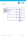
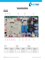
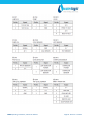
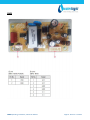
1
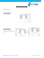
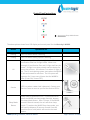
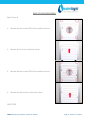
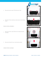
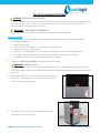
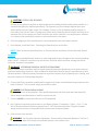
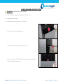
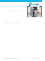
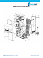
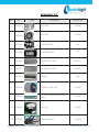
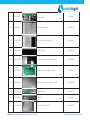
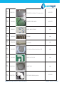
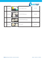
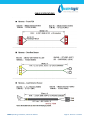
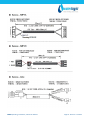
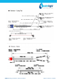
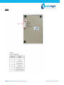
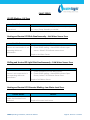
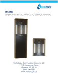
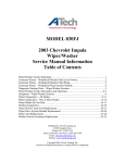
WL800 – MAX II
OPERATING, INSTALLATION, AND
SERVICE MANUAL
Waterlogic Commercial Products, LLC
11710 Stonegate Circle
Omaha, NE 68164
(800) 288-1891
www.waterlogic.us
WL800 OPERATING, INSTALLATION, AND SERVICE MANUAL
Congratulations on your choice of the Waterlogic WL800 water treatment system. The WL800 is a fully
programmable self-contained model that dispenses cold, hot, extra-hot, and premium sparkling water.
Every WL800 includes:
High Performance Multi-Stage Filtration
Recirculating Ultraviolet (UV) Purification
The Waterlogic WL800 provides exceptional quality and great tasting water with every use.
•
•
•
•
•
•
•
•
•
•
•
•
•
•
•
•
•
•
•
•
•
•
•
•
•
•
TABLE OF CONTENTS
Features and Benefits..................................................................3
Certifications ...............................................................................4
Introduction .................................................................................5
Safety Alert Symbols....................................................................5
Safety Precautions .......................................................................6
Model and Part Designations ......................................................7
Specifications...............................................................................7
Operating Instructions.................................................................8
Control Panel Instructions ...........................................................9
Hot Tank Principles of Operation ..............................................10
Flow Diagram .............................................................................11
Disassembling and Refitting Instructions ..................................12
Pre-Installation Instructions ......................................................34
Draining Instructions .................................................................37
Installation Instructions .............................................................39
Service Instructions ………………………………………… ......................41
Replacement Components ........................................................42
Hot Tank Descaling Instructions ................................................43
Drawing and Parts List ...............................................................45
Electrical Diagram ......................................................................52
Cable Specifications ...................................................................53
Circuit Diagrams ........................................................................56
PBA Location Diagrams …………………….......................................59
Fault Codes ................................................................................64
Troubleshooting ........................................................................66
Warranty ...................................................................................75
WL800 Operating, Installation, and Service Manual
Page 2 - Revision: 5-14-2015
WL800 FEATURES AND BENEFITS
Cold and Hot Water
Cold and Hot Water Selections to meet your customers demands.
High Volume Storage and Water Capacity
16 liters of Cold Water Tank Capacity and 3.5 liters of Hot Tank Capacity
Large Dispense Area
11.7 inch dispense height, ideal for filling large jogs and carafes
Child Safeguard
Hot Water safety feature to protect against accidental usage.
4-Step Filtration System
The WL800 uses a 4 stage reverse osmosis (RO) to product the best quality drinking water. It includes a
sediment filter, pre-carbon filter, reverse osmosis membrane and a post carbon filters. These filters
remove impurities and improve taste.
Energy Saving Sleep Mode
Energy saving Sleep Mode can be programmed to turn off heater after 72 hours of inactivity.
UV Sanitation
Re-circulating UV systems sanitizes the water by reducing bacterial growth giving a reassurance of fresh
clean drinking water.
WL800 Operating, Installation, and Service Manual
Page 3 - Revision: 5-14-2015
WL800 CERTIFICATIONS
Waterlogic water treatment systems have been tested, and certified to rigorous NSF and UL Standards.
We believe that performance testing and certifications validate Waterlogic as a world-leader in water
treatment systems.
WL800 Certifications Include
UL399 – Certified Drinking Water Cooler
Intertek Labs (ETL) Certified the WL800 to ANSI/UL 399 Standard for Drinking Water
Coolers.
BPA Free - Waterlogic tests for BPA and declares that all of its products are Bisphenol-A
FREE and contain no harmful BPA plastics.
Energy Star Certified
The WL800 has been tested and certified to the Energy Star, a US Environmental
Protection Agency (EPA) program that helps our customers save money and protect our
climate through superior energy efficiency.
Waterlogic is certified to ISO 9001 – Quality Management Systems (certified by
Moody International). ISO 9001 is the internationally accepted standard for
well managed organizations that have adopted the key quality management
principles to its operations to bring consistent quality products and a culture of
continuous improvement.
Safe Drinking Water Act
Waterlogic water treatment systems conform to the Safe Drinking Water Act (SWDA) “lead-free”
amendment effective January 4, 2014.
WL800 Operating, Installation, and Service Manual
Page 4 - Revision: 5-14-2015
INTRODUCTION
Carefully read and follow all instructions to ensure proper and efficient operation of your WL800.
Contact Waterlogic or an Authorized Waterlogic Dealer if you have any questions.
Waterlogic and Authorized Waterlogic Dealers employ trained service personnel who are experienced
in the installation, function and repair of Waterlogic equipment. This publication is written for use by
these qualified individuals. Waterlogic encourages users to learn about products, however, we believe
that product knowledge and service is best obtained by consulting Waterlogic or an Authorized
Waterlogic Dealer.
Waterlogic water treatment systems should be combined with selected water treatment components
to create a system specifically tailored for each application by trained and qualified personnel.
Products manufactured and marketed by Waterlogic and its affiliates are protected by patents issued or
pending in the United States and other countries.
Waterlogic reserves the right to change the specifications referred to in this literature at any time,
without prior notice. Changes or modifications not expressly approved by Waterlogic could void the
warranty and user’s authority to operate the equipment.
SAFETY ALERT SYMBOLS
Read and follow all safety information carefully. The signal words used in this manual are selected as
shown below and based on an assessment of the degree of potential injury or damage (severe or minor)
and the occurrence of injury (definitely occurs or has the potential to occur) when the warning is
ignored:
DANGER!
Indicates a situation which, when not avoided, results in death or severe injury.
WARNING!
Indicates a situation which, when not avoided, has the potential to result in death or severe
injury; and/or severe property damage.
CAUTION!
Indicates a situation which, when not avoided, results or has the potential to result in minor
injury; and/or minor property damage.
WL800 Operating, Installation, and Service Manual
Page 5 - Revision: 5-14-2015
SAFETY PRECAUTIONS
Basic safety precautions should be followed, including the following:
DANGER! If incorrectly installed, operated or maintained, this product can cause death or severe
injury. Those who install, operate, or maintain this product should be trained in its proper use, warned of
its dangers, and should read the entire manual before attempting to install, operate, or maintain this
product.
WARNING! Unit is to be used for its intended purpose as described in this manual, and untrained
individuals who use this manual assume the risk of any resulting property damage or personal injury.
WARNING! HOT WATER. Unit produces Very Hot Water up to 203oF. Water above 125oF can cause
severe burns or scalding. Keep unauthorized people and children away from the unit to avoid accidental
dispensing of hot water. Children should not use without supervision.
DANGER! ELECTRICAL SHOCK HAZARD. Always unplug from power supply prior to servicing
equipment to prevent electrical shock.
WARNING! This system to be used for water only and is not intended for use where water is
microbiologically unsafe or with water of unknown quality without adequate disinfection before or
after the system. The system is designed for the supplemental bactericidal treatment of either treated
and disinfected public drinking water, or other drinking water, which has been tested and deemed
acceptable for human consumption by the state or local health agency having jurisdiction. The system is
designed to reduce normally occurring non-pathogenic or nuisance microorganisms only. System is not
intended for treatment of contaminated water.
WARNING! Dispenser Could Tip or Fall causing serious injury. Always install unit on a firm, flat, and
level surface and secure the WL800 to the base cabinet with the screw provided to lock the components
together. Never place heavy items on top of unit and never climb, stand, or hang on unit or storage
cabinet to prevent injury and damage.
CAUTION! INDOOR USE ONLY. Do not install outdoors or where unit is in direct sunlight. Do not
install where ambient temperature goes below 50F or above 97F. Avoid high humidity and moisture.
Product life and performance will be impacted and warranty could be voided.
WL800 Operating, Installation, and Service Manual
Page 6 - Revision: 5-14-2015
MODEL/PART DESIGNATIONS
BRAND NAME
WL800
DESCRIPTION
MODEL – PART NUMBER
Waterlogic WL800 – Cold and Hot
16-MAZH2
SPECIFICATIONS
ITEM
WL800
Water Connection
¼” Quick Connect
Cold Water Temperature – Factory Set Point 41° - 5°C
Cold Water Temperature
(Adjustable) 34° - 54° F. (1.1° - 12.2°C)
Hot Water Temperature
158° - 203° F (70° - 95°C) Programmable
Recommended Service Pressure 40-60 psi (275-414 kPa) – Use Pressure Regulator
Maximum Working Pressure
60 psi (414 kPa) – Use Pressure Regulator
Environmental Temperature
35° - 100°F (2° - 37°C)
Refrigerant Gas
R134a – 2.29 oz. (65 grams) - Hi (290 psi) Low (90 psi)
R134a Pressures
High (290 psi), Low (90 psi)
SHIPPING SPECIFICATIONS
ITEM
DIMENSIONS
Width/Depth/Height
17 in. (440mm) x 20 in. (515mm) x 49.6 in. (1260mm)
Weight – Dry (w/o packaging)
Shipping Information
(length x width x height)
Shipping Weight – Dry
93 lb. (42 kg)
21.5 in. x 25 in. x 52 in.
4 units per pallet
103 lb. (46 kg)
ELECTRICAL SPECIFICATIONS
ELECTRICAL SUPPLY
15 Amp Service
COMPONENT
AMP DRAW (approximate)
Hot Tank Heater
4.45 Amps
Compressor
0.6 Amps
WL800 TOTAL
5.05 Amps
WL800 Operating, Installation, and Service Manual
+
Page 7 - Revision: 5-14-2015
OPERATING INSTRUCTIONS
Dispensing Water
Cold Water Selection
Push the cup-touch
Hot Water Selection
Press the Hot Water Safety
Button and push the cup touch
lever.
WL800 Operating, Installation, and Service Manual
Page 8 - Revision: 5-14-2015
Control Panel Instructions
Sleep Mode Button
The above picture shows front LCD display and control panel for the Waterlogic WL800 .
Button
Operational Use
Heating
LED is on when heater is working
Chilling
LED is on when cooling system is working
UV
LED is on when UV sterilization light is on. UV
sterilization filter has UV light inside. Water runs
through UV sterilization filter and UV light sterilizes the
water. UV light is on when nobody uses the device for
more than an hour. UV indicator is on when UV light is
on. The UV recirculating system starts when the WL800
is idle and unused for one hour. The UV system will
operator for 1 hour every 4 hours that the WL800 is
idle. (1 hour ON, 3 hours OFF).
Service
LED is on when a water leak is detected. Contact your
Service Center as soon as you find the Service LED on.
Sleep Mode
Button
Sleep mode is defaulted to OFF. If you would like to
place the WL800 into sleep mode manually, depress
the sleep Mode Button. After 72 hours, if the WL800
remains idle and unused, the unit will enter sleep
mode. To awaken the WL800 from sleep mode, you
will need to dispense 20 ounces of water from the
machine (hot or cold) which will start the hot tank
heater.
WL800 Operating, Installation, and Service Manual
Page 9 - Revision: 5-14-2015
HOT TANK PRINCIPLES OF OPERATION
All Waterlogic Hot Tanks have a built in Vent or
Expansion Chamber in the top of the tank except for
WL270 (GF) units.
The Vent Chamber allows for expansion of the water
when it is heated.
The chambers are separated by a welded-in tank
baffle.
Water always flows into the bottom of the tank and
out the top to the faucet.
The hot tank outlet tube has a restrictor in its base.
This ensures the reservoir is always full by allowing
more water in than out.
There is a small hole in the side of the tank outlet tube
that allows air and water to pass into the vent
chamber as it is heated.
Water in the vent chamber is suctioned back through
the outlet tube vent hole when water is dispensed.
Expansion of water as it is heated in the reservoir will
push the water out the faucet when the outlet tube
vent hole becomes plugged with debris or scale.
The small Outlet Vent Hole is susceptible to scale build
up and is a key indicator that descaling is required.
It is critical to descale the hot tank through the vent
line and outlet line on a regular basis to prevent this
problem.
Descaling through the inlet and/or outlet lines only
will not clean the vent chamber and outlet vent hole
properly.
WL800 Operating, Installation, and Service Manual
Page 10 - Revision: 5-14-2015
WL800 FLOW DIAGRAM
The WL800 is a 4-step Water Filtration system
Step 1: PLUS SENDIMENT FILTER (Part Number 16-1000). This plus sediment filter has the
functions to reduce sediment (rust, dirt, sand) from feed water and to protect membrane and
pre-carbon filter from being plugged.
Step 2: PRE-CARBON FILTER (Part Number 16-1001). This Pre-Carbon filter reduces aesthetic
chlorine, odor, volatile organic compounds (VOC’s).
Step 3: RO MEMBRANE FILTER (Part Number 16-0099). RO Membrane filter reduces water
contaminants such as pentavalent arsenic, barium, cadmium, selenium, radium 226/228,
trivalent chromium, hexavalent chromium, lead, nitrate/nitrite.
Step 4: INNO-SENSE FILTER (Part Number 16-1003). This Inno-sense filter improves taste of the
product water
WL800 Operating, Installation, and Service Manual
Page 11 - Revision: 5-14-2015
DISASSEMBLING AND REFITTING INSTRUCTIONS
Exercise Caution not to damage or deform any parts when disassembling the system.
Refit the system in the reverse order of disassembling.
Before disassembling the WL800
1. Block the main water by closing the main water supply valve.
2. Completely drain the water from the water tank.
If the water is splashed during the repair, insulation may deteriorate, resulting in danger.
3. Unplug the WL800.
4. When disassembling and refitting the unit with its side touching the ground, perform the job on a
working cloth. Without the working cloth, the product may get scratches.
Tools Needed:
•
•
•
Phillips Screwdriver
Flathead Screwdriver
Needle Nose Pliers
WL800 Operating, Installation, and Service Manual
Page 12 - Revision: 5-14-2015
REMOVING TOP COVER ASSEMBLY
1.
Remove Top cover Assembly in direction shown
2.
Remove Silicone Overheating Hose
3.
Remove the nine clips on the Cap-Main Tank Assembly
4.
Remove Cap-Main Tank Assembly in direction shown
WL800 Operating, Installation, and Service Manual
Page 13 - Revision: 5-14-2015
5.
Remove the ceramic filter in the direction shown
6.
Remove separator board in direction shown
7.
Remove Connector-Cold Water Extraction in direction
shown
WL800 Operating, Installation, and Service Manual
Page 14 - Revision: 5-14-2015
REMOVING FRONT COVER LOWER ASSEMBLY
1.
Remove Grill in direction shown
2.
Detach the Grill Tray Assembly as shown
3.
Remove the screw (THT 4X10) located on the Front Cover
Lower Assembly as shown.
4.
Press down on the Front Cover Lower Assembly and
remove in the direction shown
WL800 Operating, Installation, and Service Manual
Page 15 - Revision: 5-14-2015
REMOVING UPPER COVER LOWER ASSEMBLY
1.
Remove the two screws (THT 4X10) from the Front Cover
Upper Assembly
2.
Remove the two screws (THT 4X10) from the Front Cover
Upper Assembly
3.
Lift up the Dispensing Handles
4.
Lift the Front Cover Upper Assembly and remove in
direction shown
WL800 Operating, Installation, and Service Manual
Page 16 - Revision: 5-14-2015
5.
Remove the connector from PBA Cover Front Assembly
6.
Remove the two screws (THT 4X12) from PBA Cover Front
Assembly
7.
Remove the two screws (THT 4X8) from PBA Front
Assembly
WL800 Operating, Installation, and Service Manual
Page 17 - Revision: 5-14-2015
DISASSEMBLING FAUCET ASSEMBLY
HOT WATER FAUCET SAFETY ASSEMBLY
1.
Remove the two THT 4x10 screws from the Hot Water
Faucet Safety Assembly
2.
With a flathead screwdriver, remove the hose connected to
the Hot Water Faucet Safety Assembly
COLD WATER FAUCET ASSEMBLY
1.
Remove the two THT 4x10 screws from the Cold Water
Faucet Assembly
2.
With a flathead screwdriver, remove the hose connected to
the Cold Water Faucet Assembly
WL800 Operating, Installation, and Service Manual
Page 18 - Revision: 5-14-2015
FAUCET BRACKET
1.
Remove the four THT 4x10 screws from the Faucet Bracket
WL800 Operating, Installation, and Service Manual
Page 19 - Revision: 5-14-2015
DISASSEMBLING PBA ASSEMBLY
PBA MAIN ASSEMBLY
1.
Press down on hooks to remove the PBA Cover
2.
Remove all connectors from the PBA Assembly
3.
Remove the two screws THT 4x8 on the PBA Main Assembly
PBA SMPS
1.
Remove the three screws THT 4x8 on the PBA SMPS
WL800 Operating, Installation, and Service Manual
Page 20 - Revision: 5-14-2015
PBA Bracket
1.
Remove the two screws THT 4x10 on the PBA Bracket
Ballast
1.
Detach the connector from the Ballast
2.
Remove the two screws THT 4x8 from Ballast
WL800 Operating, Installation, and Service Manual
Page 21 - Revision: 5-14-2015
DISASSEMBLING FILTERS
FILTER
1.
Remove fittings attached to the filters with a flathead
screwdriver.
2.
Remove all Filters in direction shown.
VALVE AUTOMATION DRAIN CONTROL
1.
Remove Valve-Automation Drain Control connected to the
filter with a flathead screwdriver.
WL800 Operating, Installation, and Service Manual
Page 22 - Revision: 5-14-2015
DISASSEMBLING FILTER BRACKETS
COLD WATER CONNECTOR DRAIN ASSEMBLY
1.
Remove the Cold Water Connector Drain Cap
2.
Rotate the Cold Water Connector Drain Assembly in the
direction shown with needle nose pliers.
3.
Line up the Cold Water Connector Drain Assembly to the
groove on the Filter Bracket. Push it in the direction as
shown with needle nose pliers.
HOT WATER CONNECTOR DRAIN ASSEMBLY
1.
Remove the Hot Water Connector Drain Cap.
WL800 Operating, Installation, and Service Manual
Page 23 - Revision: 5-14-2015
2.
Rotate the Hot Water Connector Drain Assembly in the
direction shown with needle nose pliers.
3.
Line up the Hot Water Connector Drain Assembly to the
groove on the Filter Bracket. Push it in the direction as
shown with needle nose pliers.
VALVE FEED NOS
1.
Remove the connector from Valve Feed Nos
2.
Remove the fitting attached to Valve Feed Nos with a
flathead screwdriver.
WL800 Operating, Installation, and Service Manual
Page 24 - Revision: 5-14-2015
3.
Remove the single screw THT 4x8 on Valve Feed Nos.
SENSOR-E LPS ASSEMBLY
1.
Remove the fitting attached to Sensor E LPS Assembly with
a flat head screwdriver.
2.
Remove the single screw THT 4x8 on the SENSOR-E LPS
Assembly.
FILTER BRACKET
1.
Remove the four screws THT 4x10 on the Bracket Filter.
WL800 Operating, Installation, and Service Manual
Page 25 - Revision: 5-14-2015
2.
Completely remove the Bracket Filter in the direction
shown.
CLIP FILTER C2
1.
Remove the eight screws THT 4x12 on Clip Filter C2.
CAPACITOR RUNNING
1.
Remove the connector from Capacitor Running.
2.
Remove the single screw THT 4x16 on Capacitor Running.
WL800 Operating, Installation, and Service Manual
Page 26 - Revision: 5-14-2015
DISASSEMBLING MODULE ASSEMBLY BRACKETS
ULTRAVIOLET STERILIZER MODULE ASSEMBLY
1.
Remove the hose connected to the Ultraviolet Sterilizer
Module Assembly with a flathead screwdriver.
2.
Remove the Ultraviolet sterilizer in direction shown.
ULTRAVIOLET STERILIZER CLIP SUS
1.
Remove the two screws THT 4x12 on the ULTRAVIOLET
STERILIZER CLIP SUS
OVERFLOW SENSOR
1.
Remove the two rubber tubes connected to the Overflow
Sensor
WL800 Operating, Installation, and Service Manual
Page 27 - Revision: 5-14-2015
2.
Remove the two screws on the Sensor Overflow with a
Phillips screwdriver.
CTS WATER LEVEL N SENSOR
1.
Remove the clip on the CTS Water Level N Sensor with a
Flathead Screwdriver.
2.
Remove the CTS Water level N in direction shown.
CTS WATER LEVEL P SENSOR
1.
Remove the CTS Water Level P Sensor Clip with a Flathead
Screwdriver.
WL800 Operating, Installation, and Service Manual
Page 28 - Revision: 5-14-2015
2.
Remove the CTS Water Level P Sensor in direction as
shown.
COLD TEMPERATURE SENSOR ASSEMBLY
1.
Remove the two screws THT 4x10 on the Cold Temperature
Sensor Assembly
2.
Remove the Cold Temperature Assembly Sensor in
direction as shown.
STRAIGHT CONNECTOR DISASSEMBLY
1.
Remove the two screws THT 4x10 on the Straight
Connector Assembly
WL800 Operating, Installation, and Service Manual
Page 29 - Revision: 5-14-2015
FITTING
1.
Remove the fitting attached to the Main Tank Assembly
with a flathead screwdriver in direction shown.
WL800 Operating, Installation, and Service Manual
Page 30 - Revision: 5-14-2015
REAR COVER DISASSEMBLY
Rear Cover A
1.
Remove the four screws THT 4x12 on the Rear A Cover
2.
Remove Rear A Cover in direction shown
3.
Remove the four screws THT 4x12 on the Rear A Cover
4.
Remove the Rear A Cover in direction shown
AIR FILTER
WL800 Operating, Installation, and Service Manual
Page 31 - Revision: 5-14-2015
1.
Remove the two screws THT 4x10 on Air Filter
2.
Pull the Air Filter towards you and remove in the direction
shown.
REAR B COVER ASSEMBLY
1.
Remove the four screws THT 4x12 on the Rear B Cover
Assembly.
2.
Remove the Rear B Cover in the direction shown.
POWER CORD ASSEMBLY
WL800 Operating, Installation, and Service Manual
Page 32 - Revision: 5-14-2015
1.
Remove the single screw PHT 3x8 (washer) on the Power
Cord Assembly.
2.
Remove the Power Cord Assembly in direction shown.
WL800 Operating, Installation, and Service Manual
Page 33 - Revision: 5-14-2015
PRE-INSTALLATION INSTRUCTIONS
DANGER! ELECTRICAL SHOCK HAZARD.
Only qualified personnel who have read and understand this entire manual should attempt to install,
or service this unit, failure to do so could result in death or serious injury. DO NOT plug into an
electrical supply until specifically instructed.
WARNING! ALWAYS SANITIZE BEFORE USE.
Sanitize before use to eliminate any potential microbiological contaminates.
Materials Needed:
• Personal Protective Equipment. Rubber or Nitrile Safety Gloves and Protective Eyewear
• Phillips Screwdriver
• Temperature Gage
• Water Pitcher or Container to collect water from the faucet
• 5 gallon container or drain basin
• Sanitizer - Household Bleach (5.25% Sodium Hypochlorite) or Citric Acid Based Cleaner
• ¼” Plastic Tubing, at least 4 feet in length, and assorted ¼” quick connect fittings
• TDS Meter and Test Strips for measuring chlorine - Optional
1. Unpack the Waterlogic WL800 and check exterior for damage.
WARNING! WL800 IS HEAVY.
Use proper lifting aids and handling techniques to avoid injury. Use assistance as single person lift
could cause injury. Always drain before handling and transporting and handling to reduce the weight
of the unit.
2. Remove the Drip Tray. Remove screw located on the lower
front cover. Removing this screw will allow access to the
inside serviceable components
3. Press down on the Front Cover Lower Assembly and
remove in the direction shown
WL800 Operating, Installation, and Service Manual
Page 34 - Revision: 5-14-2015
Flush Filters
CAUTION! FILTER FLUSH REQUIRED.
In order for our filters to perform as represented and to provide the best quality water possible, it is
essential that filters be replaced periodically. The frequency of filter changes depends upon your
water quality and your water usage. For example, if there is a lot of sediment and/or particles in
your water, then you will have to change your filters more frequently than a location with little to no
sediment. Be sure to replace your filters whenever you notice a decline in the performance, whether
it is a drop in flow rate and/or pressure or an unusual taste in the water.
4. Flush thoroughly per filter manufacturers’ recommendation with fresh water to drain.
5. Once flushed, install the filters. Following the flow direction on the filter.
NOTE: Filters should not be flushed prior to 24 hours before installation to limit Microbial Growth.
Sanitizing
Sanitize using a household bleach solution or other approved cleaner throughout the cold and sparkling
water circuits. Follow all instructions on the sanitizer and flush with fresh water through the faucet
until odor and taste is acceptable.
WARNING! USE PROPER PERSONAL PROTECTIVE EQUIPMENT
Always ensure proper ventilation and use proper personal protective equipment such as gloves and eye
protection when using chemicals. Refer to Material Safety Data Sheet for specific requirements of each
chemical product. Take all necessary precautions to prevent sanitizer from contacting eyes, clothing, and
any other surfaces in could damage (carpets).
6. Connect 40-60 psi regulated, potable water supply to the water inlet bulkhead fitting located on the
back of the unit. Turn on water supply and check for leaks.
DANGER! ELECTRICAL SHOCK HAZARD.
Do not plug in unit unless qualified. Only qualified personnel who have read and understand this
entire manual should attempt to install or service this unit.
7. Connect WL800 to power and allow unit to fill completely.
8. Mix ½ gallon of sanitizer per directions or use Bleach Solution (1 teaspoon = 1/6 oz. = 5 ml = ½ cap
full) of household bleach (Sodium Hypochlorite 5 - 10% Concentration) with 1/2 gallon of water.
Always ensure sanitizer is compatible with stainless steel and acetal plastic.
9. Pour sanitizer into reservoir.
WARNING! Use Personal Protective Equipment. Gloves and Eye Protection Required. The first 2
or 3 gallons of water will contain concentrated sanitizer. Use extreme care!
WL800 Operating, Installation, and Service Manual
Page 35 - Revision: 5-14-2015
CAUTION! USE SANITIZER COMPATIBLE WITH STAINLESS STEEL AND ACETAL PLASTIC.
Do not allow the sanitizer solution to remain in the system for more then 10-15 minutes unless
otherwise directed by the sanitizer manufacturer.
Flushing the Sanitizer from the Machine
10. Place a pitcher, catch basin, or other container under the faucet of the WL800.
11. Flush the Cold Tank. Run several gallons of water through the faucet by dispensing cold water to
dilute and remove the sanitizer from the cold circuit. You can use chlorine test strips to evaluate the
water.
Fill the Hot Tank
12. Press the Hot Cup Touch Lever to fill the hot tank. Water will dispense from the faucet once the hot
tank is full. Flush until water is clear.
WARNING! HOT CIRCUIT IS NOT SANITIZED. WATER MUST EXCEED 171o F
Water in the hot circuit is not sanitary until the temperature over 171oF for 5 minutes.
Do Not Ingest and avoid contact until heater is turned on for at least 5 minutes.
Compressor Test
13. Heater and compressor will turn on automatically once water level has reached the full level sensor.
14. Allow unit to run for 1 hour. Check hot and cold temperatures. Cold = 41°, Hot = 187°.
15. Once the machine reaches its target temperature, the compressor and fan will shut off. Draw a
glass of cold water and verify it is has been chilled to proper temperature.
WARNING! VERY HOT WATER CAN BURN OR SCALD.
Hot water should be dispensed carefully into insulated container to avoid injury.
Drain the WL800 for Transport
16. Drain the WL800 for transportation per the Draining Instructions in this manual.
WARNING! STORE UNIT EMPTY. ALWAYS SANITIZE BEFORE REUSE.
The unit must be completely drained and sealed before storing to avoid stagnation and reduce
microbiological contamination (potential bacterial growth).
WL800 Operating, Installation, and Service Manual
Page 36 - Revision: 5-14-2015
WL800 DRAINING INSTRUCTIONS
WARNING! WL800 IS A HEAVY OBJECT.
1. Turn off water supply and disconnect from unit.
2. Unplug power supply
3. Remove drip tray and lower front panel.
Remove Grill in direction shown
Detach the Grill Tray Assembly as shown
Remove the screw (THT 4X10) located on the Front Cover
Lower Assembly as shown.
WL800 Operating, Installation, and Service Manual
Page 37 - Revision: 5-14-2015
Press down on the Front Cover Lower Assembly and
remove in the direction shown
4. Connect drain tube.
5. Replace lower front panel and drip tray.
WL800 Operating, Installation, and Service Manual
Page 38 - Revision: 5-14-2015
INSTALLATION PROCEDURES
Safety and Installation Guidelines
Ensure all Local, State, and Federal Laws and Codes including health and safety guidelines are met when
installing Waterlogic Equipment. Only qualified service technicians should attempt installation and
service of Waterlogic Equipment.
WARNING! ELECTRICAL SHOCK HAZARD. Always unplug (isolate from power supply) to prevent
electrical shock except where electrical tests are specified.
WARNING! IMPROPER SUPPLY OR CONNECTION CAN RESULT IS RISK OF SHOCK.
Connect to a 15 amp 120V 60Hz properly grounded outlet (GFI is recommended). Ensure polarity is
correct and always use a 3-prong outlet. Consult a qualified electrician if you have any questions.
WARNING! USE ONLY Waterlogic SUPPLIED POWER CORD (EL-5001-A). Locate system within 5
feet of power supply. Never use an extension cord or adapter. Do not use a damaged power cord or
plug. Keep power cord out of heavy traffic areas and away from heat sources. Do not, under any
circumstances, remove ground prong or alter the power cord. Never pull the power plug from the outlet
with a wet hand or allow the plug to get wet. Failure to use the supplied power cord will void UL
Certification and Warranty.
CAUTION! INDOOR USE ONLY. Never exposed to direct sunlight, heat sources, or ambient air
temperature above 97F (36C) or below 50F (10C). Install indoors and keep unit away from excessive
humidity. Never expose to freezing temperatures. Ensure there is adequate clearance around the unit
to allow refrigeration system condenser to dissipate heat. Warmer environments require more
clearance around the unit. Minimum clearance around all surfaces of the machine is 2-inches. Installs
where the ambient temperature exceed 80F, require a minimum of 4-inches clearance for proper heat
dissipation and efficient operation.
CAUTION! USE A WATER PRESSURE REGULATOR. Waterlogic will not be responsible for injury or
damage caused by excessive water pressure. Operating pressure must be 40 psi to 60 psi. Be aware any
of potential pressure surges caused by building/municipal pumping stations.
CAUTION! USE UV STABLIIZED SUPPLY LINES. Feed the unit with a potable ambient or cold water
supply only. Feed water over 105 F (40C) can damage the treatment components. Water block devices
and external leak detectors are strongly recommended. Locate the unit as close to the water supply and
the electrical connections as possible.
WARNING! STORE UNIT EMPTY. ALWAYS SANITIZE BEFORE USE.
The unit must be completely drained and sealed before storing to avoid stagnation and reduce
microbiological contamination (potential bacterial growth). Sanitize before use to eliminate any
potential microbiological contaminates
WL800 can be combined with RO Filtration Systems. RO will require a drain connection. Refer to all
applicable plumbing codes and standards in your area for these requirements (air gap connections and
back flow prevention may be necessary).
Pre-installation and sanitization procedures as prescribed in this manual must be performed before
installing the WL800.
WL800 Operating, Installation, and Service Manual
Page 39 - Revision: 5-14-2015
Always install indoors and place the Waterlogic WL800 on a firm, flat and stable surface.
Attach the water supply line to the 1/4” feed water inlet bulkhead fitting on the back of the unit.
Waterlogic requires the use of a water pressure regulator. Water feed pressure must be between 4060 psi. Turn on the water supply and check for leaks.
1. Connect the power cord to the back of the Waterlogic WL800 and to a 120 Volt supply.
2. Allow unit to fill.
3. Dispense Cold Water
4. Dispense Hot Water
5. Move the Waterlogic WL800 into its final operating position. Be sure that a minimum of 2”
clearance is maintained around both the sides and the back of the unit. This is important to allow
proper airflow and heat exchange of refrigeration system.
6. Level unit using the adjustable feet to level if necessary. Never install on incline.
7. Once the unit is at the target temperature(s), sample the water to ensure water meets expectations
and additional rinsing or adjustment is not required.
8. Check the unit for any leaks. External Leak Protection is always recommended.
WL800 Operating, Installation, and Service Manual
Page 40 - Revision: 5-14-2015
SERVICE REQUIREMENTS
WARNING! Read and understand the contents of this manual before attempting to service
WL800. Failure to follow the instructions in this manual could result in death, serious personal
injury, or severe property damage. Only trained and qualified technicians should attempt to
install, maintain, or service Waterlogic Equipment.
1. Visually inspect all electrical and water connections for signs of wear or damage.
DANGER! HIGH VOLTAGE ELECTRICAL HAZARD. Unplug before inspection and service.
2. Waterlogic recommends changing the UV Lamp every 12 months.
WARNING! ULTRAVIOLET RADIATION. Protect your skin and eyes against ultraviolet rays.
Never look directly at an operating UV light. Disconnect before removing UV Lamp.
CAUTION! UV LAMPS ARE HAZARDOUS. Lamps are considered Hazardous Waste and must be
disposed of accordingly. Refer to Product MSDS sheet for details.
3. The filters should be replaced every 12 months, or 2000 gallons, whichever comes first. Local water
conditions will dictate your exact filter requirements and service intervals. Flush 5 gallons of water
through the filters to rinse carbon fines. Do not rinse the filters through the unit solenoid valve(s)
and tanks if at all possible to avoid contamination.
4. Clean and sanitize external surfaces of the unit. Use soap and water or chemicals that are
compatible with ABS plastic and will not damage or degrade the product surfaces.
5. Remove and clean the Faucet. Replace as needed.
WARNING! SANITIZER MAY CONTAIN HAZARDOUS CHEMICALS. Use of proper personal
protective equipment such as rubber gloves and eye protection is required.
WL800 Operating, Installation, and Service Manual
Page 41 - Revision: 5-14-2015
REPLACEMENT COMPONENTS
Component
UV Light and Pump Assembly
Part No.
3123954
Frequency of Replacement
Every 12 months, or as required
WLUSA P/N 16-5740
Replacement parts can be obtained from Waterlogic or an Authorized Waterlogic Dealer.
See Parts Layouts, Drawings, and Lists for additional repair parts.
Hot Tank 3123938 – WLUSA P/N 16-5020 Service
Hot Tank (with controls) must be replaced at least every 5 years.
Descaling hot tank may be required on a regular basis depending
upon filtration and local water conditions. See Service Section.
NOTE:
At the end of this product’s life, ensure that it is disposed of in an environmentally friendly manner
which is fully compliant with all Federal/State/Local Requirements and Guidelines.
WL800 Operating, Installation, and Service Manual
Page 42 - Revision: 5-14-2015
DESCALING THE HOT TANK
1. The hot tank requires removal of mineral deposits (descaling) on a regular basis, depending upon
filtration and local water conditions. Descaling is an important process that removes calcium
deposits, or scale, that can build up inside a tank over time. Calcium and scale is non-toxic but left
unattended, it will hinder your unit’s performance.
Descaling should take place every 6 to 12 months to preserve the long-term health of your unit. Use
non-toxic cleaner such as ScaleKleen, DEZCAL, 20% Citric Acid Solution, or Undiluted Vinegar
Solution to remove mineral deposits as directed by the manufacturer.
WARNING! PERSONAL PROTECTIVE EQUIPMENT REQUIRED. Always ensure proper ventilation
and use rubber or nitrile gloves and eye protection when using chemicals. Refer to Material Safety
Data Sheet for specific requirements of each product.
CAUTION! STAINLESS STEEL TANK DESCALING.
The hot tank is made from stainless steel. Ensure descaling solution is compatible with stainless and
always flush the unit completely. Dispose in an environmentally safe manner.
See Hot Tank Descaling Video and training procedure located on the Partner Area of the Waterlogic
Website for more detailed instructions. www.waterlogic.us
Materials Needed:
• Personal Protective Equipment. Rubber or Nitrile Safety Gloves and Protective Eyewear
• Phillips Screwdriver
• Temperature Gauge
• Water Pitcher or Container to collect water from the faucet
• 5 gallon container or drain basin
• Citric Acid Based Cleaner
• Food Coloring
2. Mix descaler per directions and 3 drops of food coloring into the descaling cartridge.
3. Turn off Power to unit.
4. Turn off Water Supply.
5. Remove Top Cover.
WL800 Operating, Installation, and Service Manual
Page 43 - Revision: 5-14-2015
6. Remove Drip Tray and Lower Front Panel
7. Drain Unit using Supplied Drain Tube
8. Open Reservoir Cover
9. Pour Descale solution into Hot Tank using a funnel.
10. Turn on Water and Power Supplies
11. Allow unit to refill
12. Allow Descale Solution to Remain in Hot Tank for 15 minutes (length of time may vary depending on
water conditions).
13. Flush Hot Tank through Faucet
14. Replace lower front panel and drip tray.
15. Replace Reservoir Cover
16. Replace Top Cover
WARNING! HOT WATER HAZARD. Unit Produces Very Hot Water and Steam. Always use
insulated and chemically compatible containers and let unit cool down before draining the hot tank
to avoid injury.
CAUTION! REPLACE HOT TANK (HT-3021) EVERY 5 YEARS. The hot tank and it’s controls
should be replaced a minimum of every five years to ensure efficient operation.
17. Always ensure unit is performing to the customer’s satisfaction.
CAUTION! RIBBON CONNECTORS MUST BE FULLY ENGAGED. Ensure ribbon connectors are
properly engaged and fully seated in front PCB (Printed Circuit Board) to avoid
intermittent/connectivity issues any time the front hatch panel is accessed.
WARNING! REINSTALL ALL PANELS AND COVERS. Always reinstall all panels, protective covers,
and fasteners after servicing equipment. Failure to do so could result in severe personal injury
and will void the certifications and warranty of the equipment.
WL800 Operating, Installation, and Service Manual
Page 44 - Revision: 5-14-2015
WL800 EXPLODED VIEW AND PARTS LIST
WL800 Operating, Installation, and Service Manual
Page 45 - Revision: 5-14-2015
WL800 PARTS LIST
No.
P/N
Image
Description
1
3103311
CASTER-B
16-5000
2
3306158
CASTER-E
16-5005
3
3123934
FAN-UNIT ASSY
4
3122366
PUMP-BOOSTER
5
3123936
COVER-SIDE L ASSY
16-5010
6
3123937
COVER-SIDE R ASSY
16-5015
7
3101463
HANDLE
8
3123938
HEATING TANK ASSY
16-5020
9
3306113
CONNECTOR-HOT WATER DRAIN
ASSY
16-5025
10
3306116
BALLAST
16-5030
11
3123939
PBA-MAIN ASSY
16-5035
WL800 Operating, Installation, and Service Manual
WLUSA P/N
N/A
N/A
N/A
Page 46 - Revision: 5-14-2015
12
3123940
PBA-SMPS
16-5040
13
3110507
COVER-REAR A
16-5045
14
3110508
COVER-REAR B ASSY
16-5050
15
3210636
FILTER-AIR
16-5055
16
3123945
COVER-FRONT UPPER ASSY
16-5060
17
3123947
PBA-COVER FRONT ASSY
16-5065
18
3123948
COVER-FRONT LOWER ASSY
16-5070
19
3123949
TRAY ASSY
16-5075
20
3224223
GRILLE
16-5080
COVER-TOP ASSY
16-5080
21
3123950
WL800 Operating, Installation, and Service Manual
Page 47 - Revision: 5-14-2015
22
3123944
CAP-MAIN TANK ASSY
16-5090
23
3112502
CLIP-MAIN TANK SEALING
16-5095
24
3306123
SEPARATOR-BOARD
16-5100
25
3110565
SENSOR-COLD TEMPERATURE ASSY
16-5105
26
3306120
SENSOR-CTS WATER LEVEL N
16-5110
27
3306121
SENSOR-CTS WATER LEVEL P
16-5115
28
3306122
SENSOR-OVER FLOW
29
3110569
HARNESS-OVER FLOW SENSOR
ASSY
16-5120
N/A
30
3306114
FAUCET-HOT WATER SAFETY ASSY
16-5125
31
3123952
FAUCET-COLD WATER ASSY
16-5130
WL800 Operating, Installation, and Service Manual
Page 48 - Revision: 5-14-2015
32
3306115
RUBBER-FAUCET LEVER
16-5135
33
3123954
ULTRA-VIOLET STERILIZERMODULE ASSY
16-5140
34
3306125
VALVE-AUTOMATION DRAIN
CONTROL
35
3306127
CLIP-FILTER C2
16-5145
36
3103373
CONNECTOR-COLD WATER DRAIN
ASSY
16-5150
Not
shown
3105086
VALVE-FEED NOS
16-5150
Not
shown
3116166
SENSOR-E LPS ASSY
16-5155
Not
shown
3123935
SENSOR-LEAKAGE
Not
shown
3306111
BIMETAL
WL800 Operating, Installation, and Service Manual
N/A
N/A
16-5160
Page 49 - Revision: 5-14-2015
Not
shown
3306112
SENSOR-Hot Water Temperature
16-5170
Not
shown
3224211
POWER CORD ASSY
16-5175
Not
shown
3306117
SNAP RING-E-RING
N/A
Not
shown
3100029
SPRING
N/A
Not
shown
3306118
SUPPORT
N/A
Not
shown
3103235
CLIP-Ultra-Violet Sterilizer SUS
N/A
Not
shown
3123955
HOSE-UV FILTER
N/A
N/A
Not
shown
3306124
HOSE-TAP
Not
shown
3300750
FITTING-ELBOW (white)
WL800 Operating, Installation, and Service Manual
16-5185
Page 50 - Revision: 5-14-2015
Not
shown
3114063
VALVE-ELBOW CHECK
16-5185
Not
shown
3105091
FITTING-ELBOW (gray)
16-5190
Not
shown
3302908
FITTING-STRAIGHT (gray)
Not
shown
3306126
CAP-FAUCET
WL800 Operating, Installation, and Service Manual
N/A
16-5195
Page 51 - Revision: 5-14-2015
WL800 ELECTRICAL DIAGRAM
DANGER! HIGH VOLTAGE ELECTRICAL HAZARD. PCB (Printed Circuit Board) contains High
Voltage. Only trained and qualified technicians should attempt live testing.
WL800 Operating, Installation, and Service Manual
Page 52 - Revision: 5-14-2015
CABLE SPECIFICATIONS
WL800 Operating, Installation, and Service Manual
Page 53 - Revision: 5-14-2015
WL800 Operating, Installation, and Service Manual
Page 54 - Revision: 5-14-2015
WL800 Operating, Installation, and Service Manual
Page 55 - Revision: 5-14-2015
MAIN PBA
WL800 CIRCUIT DIAGRAMS
WL800 Operating, Installation, and Service Manual
Page 56 - Revision: 5-14-2015
WL800 Operating, Installation, and Service Manual
Page 57 - Revision: 5-14-2015
FRONT PBA
WL800 Operating, Installation, and Service Manual
Page 58 - Revision: 5-14-2015
PBA LOCATION DIAGRAM
MAIN PBA
WL800 Operating, Installation, and Service Manual
Page 59 - Revision: 5-14-2015
WL800 Operating, Installation, and Service Manual
Page 60 - Revision: 5-14-2015
WL800 Operating, Installation, and Service Manual
Page 61 - Revision: 5-14-2015
SMPS
WL800 Operating, Installation, and Service Manual
Page 62 - Revision: 5-14-2015
SMPS
WL800 Operating, Installation, and Service Manual
Page 63 - Revision: 5-14-2015
FAULT CODES
UV LED Blinking – UV Error
Possible Reason
UV Lamp or Pump is Not
Operational
Solution
Check Connections to UV Lamp / Pump Assembly. Replace
UV Lamp / Pump Assembly as needed.
Heating and Service LED Blink Simultaneously – Hot Water Sensor Error
Possible Reason
Sensor not connected or is not
operating within set
parameters
Solution
1. Check connection to Hot water sensor.
2. Check OHMS reading – above 900K indicates open
sensor. Below 5.2K indicates sensor short.
Replace Hot Water Sensor
Chilling and Service LED Light Blink Simultaneously – Cold Water Sensor Error
Possible Reason
Sensor is not connected or is
not operating within set
parameters
Solution
1. Check connection to Cold Water Sensor.
2. Check OHMS reading – above 690K Indicates Open
Sensor, below 7.3K indicates Sensor Short.
Replace Cold Water Sensor.
Heating and Service LED Alternate Blinking –Low Water Level Error
Possible Reason
Full level sensor has detected
water, but low level is not
detected
Solution
Check connection to low water level sensor.
Replace low water level sensor
WL800 Operating, Installation, and Service Manual
Page 64 - Revision: 5-14-2015
Chilling and Service LED Alternate Blinking – Full Water Level Error
Possible Reason
Low Level and Overflow
Sensors indicted water but full
level sensor is not detected
Solution
Check connection to low water level sensor.
Replace full water level sensor
Heating, Chilling and Service LED Sequentially Blink
Possible Reason
Overflow sensor has detected
water but neither low or full
sensors are detected
Solution
Check connections to both low and full water sensors.
Replace both Low Water and Full Water Sensors
Heating, Chilling and Service LED Blinks Simultaneously
Possible Reason
All three level sensors have
detected water
Solution
Check Feed Valve for Debris.
Clean or replace feed valve.
Service LED is On – Leak Detection Probe has detected water
Possible Reason
Dry inside of unit and leak
detector.
Solution
Check unit for leak and repair or replace faulty parts.
WL800 Operating, Installation, and Service Manual
Page 65 - Revision: 5-14-2015
TROUBLESHOOTING
POWER SUPPLY FAULT
WL800 Operating, Installation, and Service Manual
Page 66 - Revision: 5-14-2015
TROUBLESHOOTING
POWER SUPPLY FAULT - continued
WL800 Operating, Installation, and Service Manual
Page 67 - Revision: 5-14-2015
TROUBLESHOOTING
HOT WATER MALFUNCTION
WL800 Operating, Installation, and Service Manual
Page 68 - Revision: 5-14-2015
TROUBLESHOOTING
HOT WATER MALFUNCTION
WL800 Operating, Installation, and Service Manual
Page 69 - Revision: 5-14-2015
TROUBLESHOOTING
COLD WATER MALFUNCTION
WL800 Operating, Installation, and Service Manual
Page 70 - Revision: 5-14-2015
TROUBLESHOOTING
COLD WATER MALFUNCTION continued
WL800 Operating, Installation, and Service Manual
Page 71 - Revision: 5-14-2015
TROUBLESHOOTING
UV MODULE MALFUNCTION
WL800 Operating, Installation, and Service Manual
Page 72 - Revision: 5-14-2015
TROUBLESHOOTING
DISPENSING MALFUNCTION
WL800 Operating, Installation, and Service Manual
Page 73 - Revision: 5-14-2015
TROUBLESHOOTING
DISPENSING MALFUNCTION
WL800 Operating, Installation, and Service Manual
Page 74 - Revision: 5-14-2015
WATERLOGIC MANUFACTURED WATER TREATMENT SYSTEM LIMITED WARRANTY
UNITED STATES AND CANADA ONLY
Waterlogic water treatment systems are guaranteed to the original purchaser to be free of defects in
materials and workmanship for a period of three (3) years from the date of purchase, but in no event
longer than forty-eight (48) months from the date of manufacture. Waterlogic Commercial Products, LLC
(“Waterlogic”) based in the U.S.A. and its affiliated companies are not liable for any cost of removal,
installation, transportation, or any other charges which may arise in connection with a warranty claim.
This warranty does not cover damage or wear to products caused by abnormal operating conditions,
accident, abuse, misuse, unauthorized or improper alteration or repair, damage caused by or resulting
from shipping or accident, damage caused by hot water, freezing, flood, fire, or acts of God. The effects
from chlorine corrosion, scaling and normal wear are specifically excluded from this warranty. This
warranty does not cover products used outside the countries where the unit was purchased, and does not
cover products that were not installed in accordance with Waterlogic printed installation and operating
instructions obtained in training or from www.waterlogic.us. Failure to follow all instructions for operation
and maintenance voids the warranty. This warranty is not transferable.
To obtain warranty repairs or replacement, you must obtain a Return Authorization from Waterlogic. To
obtain a Return Authorization, you must submit a Return Authorization form with supporting
documentation to Waterlogic for evaluation. The form is available at www.waterlogic.us. Supporting
documentation must include, but is not limited to; proof of purchase, installation date, failure date, and
supporting installation and maintenance data. After you submit a Return Authorization form and
supporting documentation, Waterlogic will determine whether a reasonably apparent defect in materials
or workmanship covered by this limited warranty exists. If Waterlogic determines the claimed defect is
covered by this warranty, Waterlogic will, at its sole discretion, determine whether to correct the defect or
replace the unit, free of charge to you. If Waterlogic determines that the unit should be returned for
warranty service, Waterlogic will approve of return in writing and will issue a Return Authorization which
you must obtain prior to shipping the product. You are responsible for the cost of freight in to Waterlogic.
Waterlogic and its affiliated companies hereby limit the duration of any and all implied warranties to a
maximum period of three (3) years from the date of purchase including, but not limited to, the implied
warranties of merchantability and fitness for a particular purpose. Some states do not allow limitations on
how long an implied warranty lasts, so the above limitation may not apply to you. Consequential and
incidental damages are not recoverable under this warranty. Some states do not allow the exclusion or
limitation of incidental or consequential damages, so the above limitation or exclusion may not apply to
you.
This warranty gives you specific legal rights and you may also have other rights which may vary from state
to state.
New Warranty Policy issued by Waterlogic Commercial Products LLC, USA - January 10, 2014
Waterlogic Commercials Products LLC
11710 Stonegate Circle
Omaha, NE 68164
WL800 Operating, Installation, and Service Manual
Tel: (800) 288-1891
Website: waterlogic.us
Page 75 - Revision: 5-14-2015