1
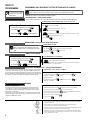
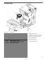
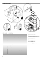
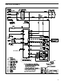
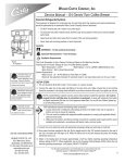
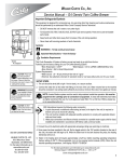
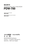
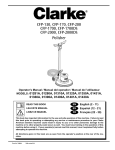
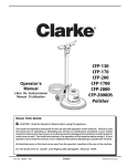
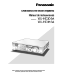
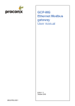
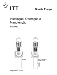
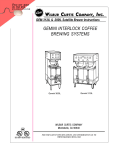
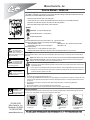
Important Safeguards Wilbur Curtis Co., Inc. Service Manual – GEM-12D This appliance is designed for commercial use. Any servicing other than cleaning and preventive maintenance should be performed by an authorized Wilbur Curtis service technician. • DO NOT immerse the unit in water or any other liquid • To reduce the risk of fire or electric shock, DO NOT open service panels. No user serviceable parts inside. • Keep hands and other items away from hot surfaces of unit during operation. • Never clean with scouring powders, bleach or harsh chemicals. Symbols WARNINGS – To help avoid personal injury Important Notes/Cautions – from the factory Sanitation Requirements Model GEM-12D CAUTION: Please use this setup procedure before attempting to use this brewer. Failure to follow the instructions can result in injury or the voiding of the warranty. IMPORTANT: Equipment to be installed to comply with applicable federal, state, or local plumbing/electrical codes having jurisdiction. Your Curtis ADS System is factory pre-set and ready to go… right from the carton. Following are the factory settings for your interlock coffee brewing systems: • Brew Temperature = 200°F • Water By-pass = ON - recommended, 36 cup brew • Brew Volume = Set to 36 cup vessel requirements. • Sleep Mode = Off System Requirements: • Water Source: 20 – 100 psi (minimum flow rate of 1 gpm) • Electrical: See attached schematic for standard model or visit www.wilburcurtis.com for your model. Setup Steps The unit should be located on a solid counter top and leveled (left to right and front to back). Connect a water line from the water filter to the brewer. NOTE: A water filtration system must be used to help maintain trouble-free operation. Air must be purged from the cartridge prior to connection to equipment. In areas with extremely hard water, we highly recommend the use of a Curtis approved water filter. For our full line of filters, please log on to www.wilburcurtis.com. NSF International requires the following water connection: 1. A quick disconnect or additional coiled tubing (at least 2x the depth of the unit) so that the machine can be moved for cleaning underneath the unit. 2. This equipment is to be installed with adequate back flow protection to comply with applicable federal, state and local codes. CAUTION: DO NOT connect this brewer to hot water. The inlet valve is not rated for hot water. WARNING: TO AVOID SCALDING, do not remove brew cone while brew light is flashing. ISO 9001:2008 Wilbur Curtis Co., Inc. Montebello, CA 90640 Tel: (323) 837-2300 www.wilburcurtis.com 3. Water pipe connections and fixtures directly connected to a potable water supply shall be sized, installed and maintained in accordance with federal, state and local codes. 1. A 3/8” NPT x 1/4” flare elbow has been supplied for water line connection. Use tubing sized sufficiently to provide a minimum of 1.0 gpm. 2. Connect the unit to an appropriate electrical power circuit. 3. Turn on the toggle (STANDBY/ON) switch behind the unit. The heating tank will start to fill. When the water level in the tank rises to the correct volume, the heating elements will energize automatically. With ADS Systems there is no danger of element burnout caused by an empty tank. 4. The heating tank will require 20 to 30 minutes to reach operating temperature (200°F) as indicated by the READY-TO- BREW indicator. 5. Prior to brewing, dispense 12 ounces of hot water through the hot water faucet. 6. Brew a cycle of at least 12 ounces, to purge the water lines of any air that may be trapped after filling. Brewing Instructions 1. Brewer should be ON (Confirm this at the rear power switch, then press the ON/OFF button). The Ready-to-Brew light should be ON. 2. Place a clean, empty satellite on the warmer deck and press the warmer switch. 3. Place a clean filter into the brew cone. 4. Pour in the correct measure of ground coffee. 5. Transfer the brew cone to the brew rails. 6. Press the Brew button. Brewing will start immediately. 1 STEPS TO PROGRAMMING PROGRAMMING ONLY REQUIRED IF FACTORY SETTINGS MUST BE CHANGED WARNING: These steps involve working with hot water. Scalding may occur if care is not taken against spilling. IMPORTANT – Before entering the program mode, allow the unit to reach brewing temperature, then press the BREW button to dispense at least 12 ounces of water to clear any air that may be trapped within the water lines. NOTE: For ALL functions you must first enter the programming mode. Brew Temperature – Factory Pre-Set to 200°F Function to set brew temperature, 170° to 204°F. Brew temperature will be indicated by READY-TO-BREW light blinking. CONFIRM/RESET BREW TEMPERATURE - Factory Preset to 200º ENTER THE PROGRAMMING MODE #1: ENTERING THE PROGRAM MODE #1 Turn OFF the power from the control panel by pressing Press and HOLD and press and RELEASE Continue HOLDING until . . starts blinking; RELEASE. Press for two seconds, then RELEASE. will start blinking. Each blink equals 2º F, starting at 170º. . To change temperature, press and HOLD . will start QUICK flashing. Each QUICK flash equals 2º F. After 204º, temperature starts over at 170º. RELEASE when the desired temperature is reached. To set and exit, press . BREW VOLUME - Factory Preset to Brewer Requirements CAUTION – Hot Water. Take precautions to place a container on the brew deck before adjusting the brew volume. An empty satellite can be used to measure the proper brew level. CHANGE BREW VOLUME ENTER THE PROGRAMMING MODE #1 Press and HOLD until hot water starts running from spray head; then RELEASE. When desired volume is reached, press To set and exit, press again to stop flow. . BREW CYCLE COUNTER TO ACCESS BREW CYCLE COUNTER ENTER THE PROGRAM MODE #2 Turn OFF the power from the Control Panel by pressing Press and HOLD Continue HOLDING and press and RELEASE until . . STOPS blinking; RELEASE. ENTER THE PROGRAMMING MODE #2: will now start a pattern of LONG and SHORT blinks. This pattern identifies the number of brew cycles. SHORT blinks indicate the brew number from one [1] to nine [9]. LONG blinks separate the 1’s, 10’s, 1,000’s and 10,000’s. SLEEP MODE (220V Models Only) – Factory Preset to Disabled This function conserves energy by automatically reducing tank temperature to 140º F when the unit sits idle for more than two hours. To recover, simply press any BREW or ON/OFF button. Once the water in the tank reaches brewing temperature, the brew cycle will automatically start. Recovery is indicated by a yellow RECOVERY light on the membrane control panel. Recovering from a SLEEP mode is faster and more efficient than heating after switching off the power. SLEEP MODE – Factory Preset to DISABLED To ENABLE Sleep Mode: UNIT MUST BE ON. Press and HOLD until SLEEP light turns ON; press Sleep Mode is now ENABLED. again. To DISABLE Sleep Mode: UNIT MUST BE ON. Press and HOLD until SLEEP light turns OFF;press Sleep Mode is now ENABLED. Setting the Temperature WARMERS Gemini warmers feature three temperature settings. Warmers are rated at 90W with High (100%); Med (60%); Low (30%). Pressing the WARMER button once will place it on High; A second time Med; Third time Low as indicated by the warmer lights. A fourth press of the warmer button turns off the warmer. When the system is turned off at the ON/OFF button, it will remember the last warmer setting. Additionally, if the warmer is off, the unit is designed to automatically turn the warmer on (Med setting) when the BREW button is pressed. To Determine Timer Setting and the Change Time: WARMER MUST BE OFF. Press and HOLD until the light comes ON and goes OFF; RELEASE. The light will start blinking. Count the blinks. Each blink = 20 minutes (maximum 200 min.). At the end of the flashing cycle, press and HOLD until the light begins QUICK flashing. The cycle will start over after 11 flashes (Note - A setting of 11 flashes is the OFF position). When you come to the desired time, RELEASE To set and exit, press By-Pass Flow Adjustment again. . . 1. Slide brew cone out to expose by-pass outlet. Place one measuring cup under the by-pass fitting and another measuring cup under the brew cone outlet. Press the LARGE brew button for 15 seconds, then press the ON/OFF button to stop the brew cycle. 2. Divide the number of ounces collected from the by-pass outlet into the total ounces collected from the spray head and by-pass. This will determine the percentage of by-pass. 3. To increase or decrease the volume of by-pass water, turn the adjustment screw on the by-pass fitting as show in the illustration (left). Turn clockwise for less water – counterclockwise for more water. 2 4. After making the adjustment, you must reprogram the brew volume to maintain the proper total amount of finished coffee brewing into the insulated server. This reprogramming is required every time you make a by-pass adjustment or when a different spray head us installed. ILLUSTRATED PARTS 1 15 14 2 11 13 10 9 16 12 4 3 5 3A 3B ITEM# PART# 1 2 3 3A 3B 4 5 5A 6 6A 7 8 9 10 11 12 12A 13 14 14A 15 15A 16 16A WC-5421 WC-3417 WC-5423 WC-5430c WC-37163d, e WC-38310 WC-970a, c WC-973d, e WC-1809 WC-2912BKb WC-3528 WC-39198 WC-8560a WC-5829 WC-1501a WC-102a, c WC-103d, e WC-39197a WC-670a, c WC-758d, e WC-847a, c WC-883d, e WC-892b WC-888b 6 6A 8 7 DESCRIPTION COVER, TOP SS GEM-12D GEM-612ILD,TL9002,312IL BREW CN, ASSY W/SPL POC BRWN STYLIZED GEMIN HOT COFF DECK, WARMER W/ASSY GEM12 312IL/612IL/12ILD/612ILD WARMER DECK, COMPLETE W/WARMER ELEMENTS GEM-12,312IL KIT, WARMER ELEMENT 100W 220V GEN USE LABEL, CAUTION HOT SURFACE GEN USE ELEMENT, WARMER ASSY 100W 120V WITH SILICONE BOOTS ELEMENT, WARMER ASSY 100W 220V FAUCET, PS/HPS SERIES HOT WTR 1/2-20 UNF AP/ALP SPOUT, HOT WATER “NO SPLASH” LEG, 4” ADJUSTABLE 3/8-16 THRD ITALIAN STYLE LABEL, BOTTOM PANEL GEM12D/612 ILD CURTIS HEATSINK, ASSY 1PH GEM612ILD GEM-12D/TL9002-10/D1000AP/T COVER, FRONT W/A GEM-12 GEM-12D/312IL/612ILD FUSE, HOLDER ASSY W/5A FUSE SWITCH, TOGGLE NON-LIT SPST 15A 125/6A 250VAC RESISTIVE SWITCH, TOGGLE NON-LIT DPST 25A 125/250VAC RESISTIVE MEMBRANE CONTRL PANEL CURTIS GEM-12D CONTROL BOARD 120V 50/60HZ GEM-12D CONTROL BOARD 220V 50/60HZ GEM12D-30 VALVE, INLET VALVE, INLET 2 GPM 240V 10W VALVE, HOT WATER 220V 17W GEM-12D VALVE, HW 120V 14W*NSI* TL9001/2/GEM-12D/600ILD/612ILD a Recommended parts to stock b Component used on earlier models of GEM12D built before 4/12, equipped with electric faucet. c Used on model GEM-12D-10. d Used on model GEM-12D-16. e Used on model GEM-12D-30. 3 ILLUSTRATED PARTS 21 B 23 32 31 20 A 18 22 34 17 26 27 19 17 18 18A 19 20 20A 21 22 23 24 25 26 26A 27 28 29 30 31 32 33 34 4 33 30 25 ITEM# PART# F 25 24 F DESCRIPTION WC-29025a WC-37122a,c WC-854d,e WC-2987 WC-37121a,c WC-853d,e WC-37132a, c WC-37357a WC-2962-101Ka WC-1438-101a WC-5231a WC-54005 WC-5432f WC-4382a WC-522a WC-906a WC-43055a WC-5527Ka WC-37008a WC-37365a WC-37266a SPRAYHEAD, PURPLE ADVANCE FLOW KIT, DUMP VALVE RIGHT VALVE, BREW DUMP RIGHT 240V 12W GEM12D/TP/TPC BYPASS ASSEMBLY, ADJUSTABLE (WC-2984,WC-2985 & WC-43011) KIT, DUMP VALVE LEFT VALVE, BREW DUMP LEFT 240V 12W GEM12D/TP/TPCELEMENT, KIT, KIT, VALVE REPAIR USE ON WC-820WDR,WC-821WDR, WC-844WDR KIT, STRAIGHT PLASTIC FITTING AND BUSHING 12MM KIT, FITTING SPRAYHEAD KYNAR SPOUT, HOT WATER “NO SPLASH” COMPOUND, SILICONE 5 OZ TANK, COMPLETE GEM-612ILD/G12D/TL9002 TANK, ASSY. COMPLETE GEM-12/ GEM-312IL GUARD, SHOCK HTNG ELMNT DOUBLE THERMOSTAT, HI LIMIT HEATER CONTROL DPST 277V 40A ELEMENT, HEATING 2KW 220V W/JAM NUTS GUARD, SHOCK RESET THERMOSTAT (WC-522) KIT, PROBE WATER LEVEL O-RING & NUT KIT, TANK LID ROUND KIT, FITTING TANK INLET KIT, FITTING TANK OVERFLOW E 28 29 a Recommended parts to stock b Component used on earlier models of GEM12D, equipped with electric faucet, built before 4/12. c Used on model GEM-12D-10. d Used on model GEM-12D-16. e Used on model GEM-12D-30. f For units with a capillary thermostat. ELECTRICAL SCHEMATIC 5 Product Warranty Information Wilbur Curtis Co., Inc. certifies that its products are free from defects in material and workmanship under normal use. The following limited warranties and conditions apply: 3 years, parts and labor, from original date of purchase on digital control boards. 2 years, part, from original date of purchase on all other electrical components, fittings and tubing. 1 year, labor, from original date of purchase on all electrical components, fittings and tubing. Additionally, Wilbur Curtis Co., Inc. warrants its grinding burrs for forty (40) months from date of purchase or 40,000 pounds of coffee, whichever comes first. Stainless steel components are warranted for two (2) years from date of purchase against leaking or pitting and replacement parts are warranted for ninety (90) days from date of purchase or for the remainder of the limited warranty period of the equipment in which the component is installed. All in-warranty service calls must have prior authorization. For authorization, call the technical support department at 1-800-995-0417. Effective date of this policy is April 1, 2003. Additional conditions may apply. Go to www.wilburcurtis.com to view the full product warranty information. CONDITIONS & EXCEPTIONS The warranty covers original equipment at time of purchase only. Wilbur Curtis Co., Inc., assumes no responsibility for substitute replacement parts installed on Curtis equipment that have not been purchased from Wilbur Curtis Co., Inc. Wilbur Curtis Co., Inc. will not accept any responsibility if the following conditions are not met. The warranty does not cover and is void under the following circumstances: 1) Improper operation of equipment: The equipment must be used for its designed and intended purpose and function. 2) Improper installation of equipment: This equipment must be installed by a professional technician and must comply with all local electrical, mechanical and plumbing codes. 3) Improper voltage: Equipment must be installed at the voltage stated on the serial plate supplied with this equipment. 4) Improper water supply: This includes, but is not limited to, excessive or low water pressure, and inadequate or fluctuating water flow rate. 5) Adjustments and cleaning: The resetting of safety thermostats and circuit breakers, programming and temperature adjustments are the responsibility of the equipment owner. The owner is responsible for proper cleaning and regular maintenance of this equipment. 6) Damaged in transit: Equipment damaged in transit is the responsibility of the freight company and a claim should be made with the carrier. 7) Abuse or neglect (including failure to periodically clean or remove lime accumulations): Manufacturer is not responsible for variation in equipment operation due to excessive lime or local water conditions. The equipment must be maintained according to the manufacturer’s recommendations. 8) Replacement of items subject to normal use and wear: This shall include, but is not limited to, light bulbs, shear disks, “0” rings, gaskets, silicone tube, canister assemblies, whipper chambers and plates, mixing bowls, agitation assemblies and whipper propellers. 9) Repairs and/or replacements are subject to our decision that the workmanship or parts were faulty and the defects showed up under normal use. All labor shall be performed during regular working hours. Overtime charges are the responsibility of the owner. Charges incurred by delays, waiting time, or operating restrictions that hinder the service technician’s ability to perform service is the responsibility of the owner of the equipment. This includes institutional and correctional facilities. Wilbur Curtis Co., Inc. will allow up to 100 miles, round trip, per in-warranty service call. RETURN MERCHANDISE AUTHORIZATION: All claims under this warranty must be submitted to the Wilbur Curtis Company Technical Support Department prior to performing any repair work or return of this equipment to the factory. All returned equipment must be repackaged properly in the original carton. No units will be accepted if they are damaged in transit due to improper packaging. NO UNITS OR PARTS WILL BE ACCEPTED WITHOUT A RETURN MERCHANDISE AUTHORIZATION (RMA). RMA NUMBER MUST BE MARKED ON THE CARTON OR SHIPPING LABEL. All in-warranty service calls must be performed by an authorized service agent. Call the Wilbur Curtis Technical Support Department to find an agent near you. ECN 16832 10/01/15 @ 13.4 rev C WILBUR CURTIS CO., INC. 6913 Acco St., Montebello, CA 90640-5403 USA | Phone: 800-421-6150 Fax: 323-837-2410 Technical Support Phone: 800-995-0417 (M-F 5:30 a.m. - 4:00 p.m. PST) Email: [email protected] | Site: www.wilburcurtis.com FOR THE LATEST SPECIFICATION INFORMATION GO TO WWW.WILBURCURTIS.COM Printed in U.S.A. 10/15 F-3191-S Rev C