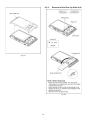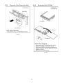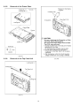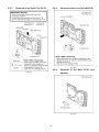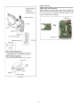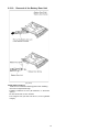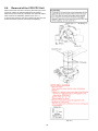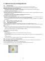
1
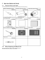
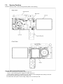
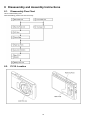
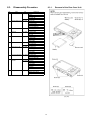
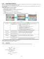
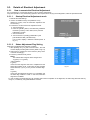
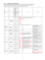
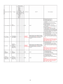
ORDER NO. DSC1302004CE
B26
Digital Camera
Model No. DMC-XS1P
DMC-XS1PC
DMC-XS1PU
DMC-XS1EB
DMC-XS1EE
DMC-XS1EF
DMC-XS1EG
DMC-XS1EP
DMC-XS1GA
DMC-XS1GC
DMC-XS1GF
DMC-XS1GK
DMC-XS1GN
DMC-XS1GT
Colour
(W)..........White Type
(K)...........Black Type
(R)...........Red Type (except PC)
(WA)........White Type (only EB/EG/EP)
(V)............Violet Type (only EB/EF/EG/EP/GC/GF/GN)
© Panasonic Corporation 2013 Unauthorized copying and distribution is a violation of law.
TABLE OF CONTENTS
PAGE
1 Safety Precautions -----------------------------------------------3
1.1. General Guidelines ----------------------------------------3
1.2. Leakage Current Cold Check ---------------------------3
1.3. Leakage Current Hot Check (See Figure. 1)--------3
1.4. How to Discharge the E.Capacitor on Flash
Top P.C.B. ----------------------------------------------------4
2 Warning --------------------------------------------------------------5
2.1. Prevention of Electrostatic Discharge (ESD)
to Electrostatically Sensitive (ES) Devices ----------5
2.2. How to Recycle the Lithium Ion Battery (U.S.
Only)-----------------------------------------------------------5
3 Service Navigation------------------------------------------------6
3.1. Introduction --------------------------------------------------6
3.2. Important Notice -------------------------------------------6
3.3. General Description About Lead Free Solder
(PbF) ----------------------------------------------------------7
3.4. How to Define the Model Suffix (NTSC or PAL
model)---------------------------------------------------------8
4 Specifications ---------------------------------------------------- 12
5 Location of Controls and Components------------------ 13
6 Service Mode ----------------------------------------------------- 15
6.1. Error Code Memory Function ------------------------- 15
7 Service Fixture & Tools --------------------------------------- 18
7.1. Service Fixture and Tools ------------------------------ 18
7.2. When Replacing the Main P.C.B. -------------------- 18
7.3. Service Position ------------------------------------------ 19
8 Disassembly and Assembly Instructions --------------- 20
8.1. Disassembly Flow Chart-------------------------------- 20
8.2. P.C.B. Location ------------------------------------------- 20
8.3. Disassembly Procedure -------------------------------- 21
8.4. Removal of the CCD FPC Unit ----------------------- 28
9 Measurements and Adjustments -------------------------- 29
9.1. Introduction ------------------------------------------------ 29
9.2. Before Disassembling the unit ------------------------ 29
9.3. Details of Electrical Adjustment----------------------- 31
9.4. After Adjustment------------------------------------------ 35
10 Maintenance ------------------------------------------------------ 36
10.1. Cleaning Lens and LCD Panel ----------------------- 36
11 Block Diagram --------------------------------------------------- 37
11.1. Overall Block Diagram ---------------------------------- 37
11.2. Flash / Top Block Diagram ----------------------------- 38
11.3. Sub Operation Block Diagram ------------------------ 38
12 Wiring Connection Diagram --------------------------------- 39
12.1. Interconnection Diagram ------------------------------- 39
PAGE
2
1 Safety Precautions
1.1.
General Guidelines
1.3.
1. IMPORTANT SAFETY NOTICE
There are special components used in this equipment
which are important for safety. These parts are marked by
2.
3.
4.
5.
1. Plug the AC cord directly into the AC outlet. Do not use
an isolation transformer for this check.
2. Connect a 1.5 kΩ, 10 W resistor, in parallel with a 0.15 μF
capacitor, between each exposed metallic part on the set
and a good earth ground, as shown in Figure. 1.
3. Use an AC voltmeter, with 1 kΩ/V or more sensitivity, to
measure the potential across the resistor.
4. Check each exposed metallic part, and measure the voltage at each point.
5. Reverse the AC plug in the AC outlet and repeat each of
the above measurements.
6. The potential at any point should not exceed 0.75 V RMS.
A leakage current tester (Simpson Model 229 or equivalent) may be used to make the hot checks, leakage current must not exceed 1/2 mA. In case a measurement is
outside of the limits specified, there is a possibility of a
shock hazard, and the equipment should be repaired and
rechecked before it is returned to the customer.
in the Schematic Diagrams, Circuit Board Layout,
Exploded Views and Replacement Parts List. It is essential that these critical parts should be replaced with manufacturer’s specified parts to prevent X-RADIATION,
shock, fire, or other hazards. Do not modify the original
design without permission of manufacturer.
An Isolation Transformer should always be used during
the servicing of AC Adaptor whose chassis is not isolated
from the AC power line. Use a transformer of adequate
power rating as this protects the technician from accidents resulting in personal injury from electrical shocks. It
will also protect AC Adaptor from being damaged by accidental shorting that may occur during servicing.
When servicing, observe the original lead dress. If a short
circuit is found, replace all parts which have been overheated or damaged by the short circuit.
After servicing, see to it that all the protective devices
such as insulation barriers, insulation papers shields are
properly installed.
After servicing, make the following leakage current
checks to prevent the customer from being exposed to
shock hazards.
1.2.
Leakage Current Hot Check
(See Figure. 1)
Leakage Current Cold Check
1. Unplug the AC cord and connect a jumper between the
two prongs on the plug.
2. Measure the resistance value, with an ohmmeter,
between the jumpered AC plug and each exposed metallic cabinet part on the equipment such as screwheads,
connectors, control shafts, etc. When the exposed metallic part has a return path to the chassis, the reading
should be between 1 MΩ and 5.2 MΩ. When the exposed
metal does not have a return path to the chassis, the
reading must be infinity.
Figure. 1
3
1.4.
How to Discharge the E.Capacitor on Flash Top P.C.B.
CAUTION:
• Be sure to discharge the E.Capacitor on Flash Top P.C.B. before disassembling.
• Be careful of the high voltage circuit on Flash Top P.C.B. when servicing.
[Discharging Procedure]
1. Put the insulation tube on the lead part of resistor (ERG5SJ102:1kΩ /5W).
(An equivalent type of resistor may be used.)
2. Put the resistor between both terminals of E.Capacitor on the Flash Top P.C.B. for approx. 5 seconds.
3. After discharging, confirm that the E.Capacitor voltage is lower than 10V by using a voltmeter.
Fig. F1
4
2 Warning
2.1.
Prevention of Electrostatic Discharge (ESD) to Electrostatically
Sensitive (ES) Devices
Some semiconductor (solid state) devices can be damaged easily by static electricity. Such components commonly are called Electrostatically Sensitive (ES) Devices.
The following techniques should be used to help reduce the incidence of component damage caused by electrostatic discharge
(ESD).
1. Immediately before handling any semiconductor component or semiconductor-equipped assembly, drain off any ESD on your
body by touching a known earth ground. Alternatively, obtain and wear a commercially available discharging ESD wrist strap,
which should be removed for potential shock reasons prior to applying power to the unit under test.
2. After removing an electrical assembly equipped with ES devices, place the assembly on a conductive surface such as aluminum foil, to prevent electrostatic charge buildup or exposure of the assembly.
3. Use only a grounded-tip soldering iron to solder or unsolder ES devices.
4. Use only an antistatic solder removal device. Some solder removal devices not classified as “antistatic (ESD protected)” can
generate electrical charge sufficient to damage ES devices.
5. Do not use freon-propelled chemicals. These can generate electrical charges sufficient to damage ES devices.
6. Do not remove a replacement ES device from its protective package until immediately before you are ready to install it. (Most
replacement ES devices are packaged with leads electrically shorted together by conductive foam, aluminum foil or comparable conductive material).
7. Immediately before removing the protective material from the leads of a replacement ES device, touch the protective material
to the chassis or circuit assembly into which the device will be installed.
CAUTION :
Be sure no power is applied to the chassis or circuit, and observe all other safety precautions.
8. Minimize bodily motions when handling unpackaged replacement ES devices. (Otherwise harmless motion such as the
brushing together of your clothes fabric or the lifting of your foot from a carpeted floor can generate static electricity (ESD) sufficient to damage an ES device).
2.2.
How to Recycle the Lithium Ion Battery (U.S. Only)
5
3 Service Navigation
3.1.
Introduction
This service manual contains technical information, which allow service personnel’s to understand and service this model.
Please place orders using the parts list and not the drawing reference numbers.
If the circuit is changed or modified, the information will be followed by service manual to be controlled with original service manual.
3.2.
3.2.1.
Important Notice
CCD FPC UNIT:
• The image sensor (CCD FPC) unit which are connected to the lens unit with 3 screws.
These screws are adjusted for the Optical tilt.
During servicing, if one of CCD FPC fixing screws are loosened, the Optical tilt adjustment must be performed.
About the Optical tilt adjustment, refer to the “9.3.2. Adjustment Specifications” for details.
3.2.2.
P.C.B.:
• In order to remove Main P.C.B., it is necessary to remove the solder (3 points) of the battery terminal.
It is judged that the analysis of the Main P.C.B. which the battery terminal separated is difficult.
So the Main P.C.B. is unit exchange.
Please fix individually about the Flash Top P.C.B..
3.2.3.
LENS UNIT:
The minimum replacement part size of the Lens part is as shown below.
When servicing, replace the following numbered replacement part size as the smallest size.
3.2.4.
About Flexible Cable and Connector
Do not touch carelessly so that the foreign body should not adhere to the terminal part of flexible cable and connector.
Wipe off with a clean cloth and the cotton bud, etc. when the terminal part is dirty.
6
3.3.
General Description About Lead Free Solder (PbF)
The lead free solder has been used in the mounting process of all electrical components on the printed circuit boards used for this
equipment in considering the globally environmental conservation.
The normal solder is the alloy of tin (Sn) and lead (Pb). On the other hand, the lead free solder is the alloy mainly consists of tin
(Sn), silver (Ag) and Copper (Cu), and the melting point of the lead free solder is higher approx.30°C (86°F) more than that of the
normal solder.
Distinction of P.C.B. Lead Free Solder being used
Service caution for repair work using Lead Free Solder (PbF)
• The lead free solder has to be used when repairing the equipment for which the lead free solder is used.
(Definition: The letter of “PbF” is printed on the P.C.B. using the lead free solder.)
• To put lead free solder, it should be well molten and mixed with the original lead free solder.
• Remove the remaining lead free solder on the P.C.B. cleanly for soldering of the new IC.
• Since the melting point of the lead free solder is higher than that of the normal lead solder, it takes the longer time to melt the
lead free solder.
• Use the soldering iron (more than 70W) equipped with the temperature control after setting the temperature at 350±30°C
(662±86°F).
Recommended Lead Free Solder (Service Parts Route.)
• The following 3 types of lead free solder are available through the service parts route.
RFKZ03D01KS-----------(0.3mm 100g Reel)
RFKZ06D01KS-----------(0.6mm 100g Reel)
RFKZ10D01KS-----------(1.0mm 100g Reel)
Note
* Ingredient: tin (Sn) 96.5%, silver (Ag) 3.0%, Copper (Cu) 0.5%, Cobalt (Co) / Germanium (Ge) 0.1 to 0.3%
7
3.4.
How to Define the Model Suffix (NTSC or PAL model)
There are seven kinds of DMC-XS1, regardless of the colours.
• a) DMC-XS1 (Japan domestic model)
• b) DMC-XS1P/PC
• c) DMC-XS1EB/EF/EG/EP
• d) DMC-XS1EE
• e) DMC-XS1GT
• f) DMC-XS1GN
• g) DMC-XS1PU/GA/GC/GF/GK
What is the difference is that the “INITIAL SETTINGS” data which is stored in Flash-ROM mounted on Main P.C.B..
3.4.1.
Defining methods:
To define the model suffix to be serviced, refer to the nameplate which is putted on the bottom side of the Unit.
NOTE:
After replacing the Main P.C.B., be sure to achieve adjustment.
The service software is available at “TSN Website”.
8
3.4.2.
INITIAL SETTINGS:
After replacing the Main P.C.B., make sure to perform the initial settings after achieving the adjustment by ordering the following
procedure in accordance with model suffix of the unit.
1. IMPORTANT NOTICE:
Before proceeding Initial settings, make sure to read the following CAUTIONS.
2. PROCEDURES:
• Precautions: Read the above “CAUTION 1” and “CAUTION 2”, carefully.
• Preparation:
- Attach the Battery.
(Since this unit has built-in memory, it can be performed without inserting memory card.)
1. Turn the Power on.
2. Press the [ MODE ] button, and select the [ NORMAL PICTURE ] mode by Cursor buttons, then press the [ MENU/SET ]
button.
3. Turn the Power off.
(If the unit is other than [ NORMAL PICTURE ] mode, it does not display the initial settings menu.)
• Step 1. The temporary cancellation of “INITIAL SETTINGS”:
Press the [ PLAYBACK ] button, “[ UP ] of Cursor button” and “[ W ] side of Zoom button” simultaneously, turn the Power on.
• Step 2. The cancellation of “INITIAL SETTINGS”:
Press the [ PLAYBACK ] button in order to enter the [ PLAYBACK ] mode.
Press the [ MENU/SET ] button and “[ LEFT ] of Cursor button” simultaneously, turn the Power off.
The LCD displays the “ ! ” mark before the unit powers down.
• Step 3. Turn the Power on:
Turn the Power on.
9
• Step 4. Display the INITIAL SETTING:
While pressing [ MENU/SET ] button and “[ RIGHT ] of Cursor button” simultaneously, turn the Power off.
The “INITIAL SETTINGS” menu is displayed.
There are two kinds of “INITIAL SETTINGS” menu form as follows:
[CASE 1. After replacing Main P.C.B.]
When Main P.C.B. has just been replaced, all of the model suffix is displayed as follows. (Five pages in total)
[CASE 2. Other than “After replacing Main P.C.B.”]
• Step 5. Choose the model suffix in “INITIAL SETTINGS”: (Refer to “CAUTION 1”)
[Caution: After replacing Main P.C.B.]
The model suffix can been chosen, JUST ONE TIME.
Once one of the model suffix have been chosen, the model suffix lists will not be displayed, thus, it can not be changed.
Therefore, select the area carefully.
Select the area with pressing “[ UP ] / [ DOWN ] of Cursor buttons”.
10
• Step 6. Set the model suffix in “INITIAL SETTINGS”:
Press the “[ RIGHT ] of Cursor buttons”.
The only set area is displayed, and then press the “[ RIGHT ] of Cursor buttons” after confirmation.
(The unit is powered off automatically.)
• Step 7. CONFIRMATION:
Confirm the display of “PLEASE SET THE CLOCK” in concerned language when the unit is turned on again.
When the unit is connected to PC with USB cable, it is detected as removable media.
(When the “GK” or “GT” model suffix is selected, the display shows “PLEASE SET THE CLOCK” in Chinese.)
1) As for your reference, major default setting condition is as shown in the following table.
• Default setting (After “INITIAL SETTINGS”)
a)
b)
c)
d)
e)
f)
g)
h)
i)
j)
k)
l)
m)
n)
o)
MODEL
DMC-XS1(Japan domestic model)
DMC-XS1P
DMC-XS1PC
DMC-XS1PU
DMC-XS1EB
DMC-XS1EE
DMC-XS1EF
DMC-XS1EG
DMC-XS1EP
DMC-XS1GA
DMC-XS1GC
DMC-XS1GF
DMC-XS1GK
DMC-XS1GN
DMC-XS1GT
VIDEO OUTPUT
NTSC
NTSC
NTSC
NTSC
PAL
PAL
PAL
PAL
PAL
PAL
PAL
PAL
PAL
PAL
NTSC
11
LANGUAGE
Japanese
English
English
Spanish
English
Russian
French
English
English
English
English
English
Chinese (simplified)
English
Chinese (traditional)
DATE
Year/Month/Date
Month/Date/Year
Month/Date/Year
Month/Date/Year
Date/Month/Year
Date/Month/Year
Date/Month/Year
Date/Month/Year
Date/Month/Year
Date/Month/Year
Date/Month/Year
Date/Month/Year
Year/Month/Date
Date/Month/Year
Year/Month/Date
REMARKS
4 Specifications
The following specification is for DMC-XS1P/DMC-FH10P.
Some specifications may differ depending on model suffix.
12
5 Location of Controls and Components
The following description is for DMC-XS1P.
Some descriptions may differ depending on model suffix.
13
14
6 Service Mode
6.1.
Error Code Memory Function
1. General description
This unit is equipped with history of error code memory function, and can be memorized 16 error codes in sequence from the
latest. When the error is occurred more than 16, the oldest error is overwritten in sequence.
The error code is not memorized when the power supply is shut down forcibly (i.e.,when the unit is powered on by the battery,
the battery is pulled out) The error code is memorized to Flash-ROM when the unit has just before powered off.
2. How to display
The error code can be displayed by ordering the following procedure:
• Preparation
- Attach the Battery.
(Since this unit has built-in memory, it can be performed without inserting memory card.)
1. Turn the Power on.
2. Press the [ MODE ] button, and select the [ NORMAL PICTURE ] mode by Cursor buttons, then press the [ MENU/SET ]
button.
3. Turn the Power off.
(If the unit is other than [ NORMAL PICTURE ] mode, it does not display the initial settings menu.)
• Step 1. The temporary cancellation of “INITIAL SETTINGS”:
Press the [ PLAYBACK ] button ,“[ UP ] of Cursor button” and “[ W ] side of Zoom button” simultaneously, turn the Power on.
• Step 2. Execute the error code display mode:
Press the [ PLAYBACK ] button in order to enter the [ PLAYBACK ] mode.
Press in order of [ PLAYBACK ] button, [ SHUTTER BUTTON ] fully, and “[ LEFT ] of Cursor button”.
Finally those states are press simultaneously.
The display is changed as shown below when the above buttons are pressed simultaneously.
Normal display → Error code display → Operation history display →Normal display →.....
Example of Error Code Display
15
Error Code List
The error code consists of 8 bits data and it shows the following information.
16
Important notice about “Error Code List”
1) About “*” indication:
The third digit from the left is different as follows.
- In case of 0 (example: 18001000)
When the third digit from the left shows “0”, this error occurred under the condition of INITIAL SETTINGS has been
completed.
It means that this error is occurred basically at user side.
- In case of 8 (example: 18801000)
When the third digit from the left shows “8”, this error occurred under the condition of INITIAL SETTINGS has been
released.
(Example; Factory assembling-line before unit shipment, Service mode etc.)
It means that this error is occurred at service side.
2) About “?” indication: (“18*0 0?01” to “18*0 0?60”):
The third digit from the right shows one of the hexadecimal (“0” to “F”) character.
• Step 3. How to exit from Error Code display mode:
Simply, turn the power off. (Since Error code display mode is executed under the condition of temporary cancellation of “INITIAL SETTINGS”, it wake up with normal condition when turn off the power.)
NOTE:
The error code can not be initialized.
17
7 Service Fixture & Tools
7.1.
Service Fixture and Tools
The following Service Fixture and tools are used for checking and servicing this unit.
7.2.
When Replacing the Main P.C.B.
After replacing the Main P.C.B., be sure to achieve adjustment.
The service software is available at “TSN Website”.
18
7.3.
Service Position
Check the Flash Top P.C.B., when servicing this DSC.(Refer to the following.)
CAUTION. (When servicing Flash Top P.C.B.)
1. Be sure to discharge the E.Capacitor on Flash Top P.C.B..
Refer to “How to Discharge the E.Capacitor on Flash Top P.C.B.”.
The E.Capacitor voltage is not lowered soon even if the AC Cord is unplugged or the battery is removed.
2. Be careful of the high voltage circuit on Flash Top P.C.B..
3. DO NOT allow other parts to touch the high voltage circuit on Flash Top P.C.B..
19
8 Disassembly and Assembly Instructions
8.1.
Disassembly Flow Chart
This is a disassembling chart.
When assembling, perform this chart conversely.
8.2.
P.C.B. Location
20
8.3.
Disassembly Procedure
No.
Item
1
Rear Case Unit
Fig
(Fig. D1)
2
(Fig. D2)
Rear Op Plate Unit (Fig. D3)
3
Front Case Unit
(Fig. D4)
4
LCD Unit
(Fig. D5)
5
Frame Plate
(Fig. D6)
6
Top Case Unit
(Fig. D7)
7
Flash Top P.C.B.
(Fig. D8)
(Fig. D9)
8
Lens Unit (W/CCD) (Fig. D10)
9
Main P.C.B.
Speaker
(Fig. D11)
(Fig. D12)
10
Battery Door Unit
(Fig. D13)
8.3.1.
Removal of the Rear Case Unit
Removal
Memory Card
Battery
2 Screws (A)
3 Screws (B)
Rear Case Unit
1 Screw (C)
1 Locking tab
2 Hooking parts
Connector (A)
Rear Op Plate Unit
1 Locking tab
Front Case Unit
2 Locking tabs
Connector (B)
LCD Unit
1 Screw (D)
1 Locking tab
1 Convex
Frame Plate
2 Locking tabs
Top Case Unit
(Discharge the E.Capacitor)
Connector (C)
1 Screw (E)
1 Locking tab
2 Convexes
Flash Top P.C.B.
Connector (D)
Connector (E)
Lens Unit (W/CCD)
Terminal Cover
3 Solders
1 Screw (F)
2 Convexes
Main P.C.B.
2 Solders
Speaker
Battery Door Shaft
Battery Door Spring
Battery Door Unit
(Fig. D1)
21
8.3.2.
Removal of the Rear Op Plate Unit
(Fig. D2)
(Fig. D3)
22
8.3.3.
Removal of the Front Case Unit
8.3.4.
Removal of the LCD Unit
(Fig. D4)
(Fig. D5)
23
8.3.5.
Removal of the Frame Plate
(Fig. D6)
8.3.6.
Removal of the Top Case Unit
(Fig. D8)
(Fig. D7)
24
8.3.7.
Removal of the Flash Top P.C.B.
8.3.8.
Removal of the Lens Unit (W/CCD)
(Fig. D10)
8.3.9.
(Fig. D9)
Removal of the Main P.C.B. and
Speaker
(Fig. D11)
25
[ When Installing ]
CATION: Before soldering the Terminal A (Connecting part
of Main P.C.B. and Frame Unit).
Before soldering the Terminal A, make sure to tighten the
“Screw (F)” first in order to eliminate the gap between Main
P.C.B. and Frame Unit. Otherwise, soldered terminal A part
may be damaged after assembling.
(Fig. D12)
26
8.3.10. Removal of the Battery Door Unit
(Fig. D13)
NOTE: (When Installing)
Make sure to confirm the following points when installing:
• The Screw is tightened enough.
• Installing conditions are fine. (No distortion, no abnormalspace.)
• No dust and/or dirt on Lens surfaces.
• LCD image is fine. (No dust and dirt on it, and no gradient
images.)
27
8.4.
Removal of the CCD FPC Unit
When remove the CCD FPC Unit once (the screw (G) is loosened even a little), the optical tilt adjustment is required.
When loosen the screw (G), necessary the optical tilt adjustment at the end of assembling. (Refer to item “9.3.2.”)
To prevent the CCD FPC Unit from catching the dust and dirt,
do not remove the CCD FPC Unit except for replacing.
(Fig. D14)
28
9 Measurements and Adjustments
9.1.
Introduction
When servicing this unit, make sure to perform the adjustments necessary based on the part(s) replaced.
Before disassembling the unit, it is recommended to back up the camera data stored in Flash-ROM as a data file.
IMPORTANT NOTICE (After replacing the Main P.C.B.)
After replacing the Main P.C.B., it is necessary to use the “DIAS” software to allow the release of adjustment flag(s).
The Adjustment software “DIAS” is available at “TSN Website”.
*DIAS (DSC Integrated Assist Software)
NOTE: (When replacing the Lens unit and CCD FPC unit)
• When the CCD FPC unit is unavoidably removed for Lens unit and CCD FPC unit replaced, an optical tilt adjustment is necessary after parts are exchanged.
• The adjustment software (DSC_Tilt) is necessary to execute an optical tilt adjustment.
• The adjustment software “DSC_Tilt” is available at “TSN Website”.
NOTE: (When replacing the Main P.C.B.)
• Number of necessary adjustment items decreases by copying the backup data to new Main P.C.B. when adjustment data in old
Main P.C.B. can be read by ROM_BACKUP “DSC→SD” in “9.2.2. Flash-ROM Data Backup”.
For more details, please refer an item “Main P.C.B. (to which the backup data was copied)” in the table of “9.3.2. Adjustment
Specifications”.
9.2.
9.2.1.
Before Disassembling the unit
Initial Setting Release
The cameras specification are initially set in accordance with model suffix (such as EB/EG/GK/GC and so on.).
Unless the initial setting is not released, an automatic alignment software in the camera is not able to be executed when the alignment is carried out.
Note:
The initial setting should be again done after completing the alignment. Otherwise, the camera may not work properly.
Therefore as a warning, the camera display a warning symbol “ ! ” on the LCD monitor every time the camera is turned off.
Refer to the procedure described in “3.4.2. INITIAL SETTINGS” for details.
[ How to Release the camera initial setting ]
Preparation:
• Attach the Battery.
(Since this unit has built-in memory, it can be performed without inserting memory card.)
1. Turn the Power on.
2. Press the [ MODE ] button, and select the [ NORMAL PICTURE ] mode by Cursor buttons, then press the [ MENU/SET ] button.
3. Turn the Power off.
(If the unit is other than [ NORMAL PICTURE ] mode, it does not display the initial settings menu.)
Step 1. The temporary cancellation of “INITIAL SETTINGS”:
Press the [ PLAYBACK ] button ,“[ UP ] of Cursor button” and “[ W ] side of Zoom button” simultaneously, turn the Power on.
Step 2. Cancellation of “INITIAL SETTINGS”:
Press the [ PLAYBACK ] button in order to enter the [ PLAYBACK ] mode.
Press the [ MENU/SET ] button and “[ LEFT ] of Cursor button” simultaneously, turn the Power off.
The LCD displays the “ ! ” mark before the unit powers down.
29
9.2.2.
Flash-ROM Data Backup
Number of necessary adjustment items decreases by copying the backup data to new Main P.C.B. when adjustment data in old
Main P.C.B. is usually read by ROM_BACKUP “DSC→SD”.
It is recommended to backup the Flash-ROM data as the way of return when trouble occurs before disassembling the unit depending on each case.
[ ROM_BACKUP (Method of Non-PC backup) ]
1. Insert the memory card into the camera.
2. Set the camera to “Temporary cancellation of the initial settings”.
3. Select the “SETUP” menu.
From the “SETUP” menu, select “ROM_BACKUP”.
NOTE:
This item is not listed on the customer's “SETUP” menu.
4. When this “ROM_BACKUP” item is selected, the following submenus are displayed.
Fig.2-1
[ DSC Integrated Assist Software (Method of Using PC) ]
Same as TATSUJIN software for previous models.
9.2.3.
Light Box
If using VFK1164TDVLB Light Box, remove the lens connection ring by loosing three hexagon screws.
Fig.2-2
30
9.3.
9.3.1.
Details of Electrical Adjustment
How to execute the Electrical Adjustment
It is not necessary to connect the camera to a PC to perform adjustments.
“Flag reset operation” and “Initial setting operation” are required when carrying out the alignment, follow the procedure below.
9.3.1.1.
Startup Electrical Adjustment mode
1. Release the initial settings.
2. Insert a recordable memory card (32MB or more).
(Without a momery card, the automatic adjustment can
not executed.)
3. Procedure to set the camera into adjustment mode:
a. Turn the Power on.
b. Press the [ MODE ] button, and select the [ NORMAL
PICTURE ] mode by Cursor button, then press the
[ MENU/SET ] button.
c. Turn the Power off.
d. Turn the Power on pressing [ MENU/SET ] and
[ MOTION PICTURE ] simultaneously.
LCD monitor displays “SERVICE MODE”.(Refer to
Fig. 3-1)
9.3.1.2.
Fig.3-1
Status Adjustment Flag Setting
Reset (Not yet adjusted) the status flag condition.
1. After pressing the “[ W ] side of Zoom button”, the LCD
monitor displays the Flag status screen (Refer to Fig.3-2)
2. Select item by pressing the Cursor buttons. (Gray cursor
is moved accordingly.)
3. Press the [ Delete/Cancel ] button.
NOTE:
The selected item's flag has been changed from
“F (green)” to “0 (yellow)”.
*Flag conditions:
F (green)
means that the alignment has been completed and the
status flag condition is set. In this case, the flag condition
Fig.3-2
should be reset, if you try to carry out the automatic alignment.
0 (yellow)
means that the alignment has been not “completed” and
the status flag condition is “reset”. In this case, automatic
alignment is available.
• In case of setting the status flag into set condition again without completion of the alignment, the status flag should be SET by
using PC, or UNDO by using ROM BACKUP function.
31
9.3.1.3.
Execute Adjustment
(In case of “OIS Adjustment”)
1. Perform step “9.3.1.1.” to “9.3.1.2.”, to reset the OIS flag
status “F” (Set) to “0” (Reset)
2. Press “[ W ] side of the Zoom button” after Flag reset.
OIS Adjustment screen is displayed on the LCD panel.
(Refer to Fig.3-3)
3. Press the [ Shutter ] button.
The adjustment will start automatically.
Fig.3-3
4. When the adjustment is completed successfully, adjustment report menu appears with Green OK on the LCD
monitor. (Refer to Fig.3-4)
Fig.3-4
9.3.1.4.
Attention point during Adjustment
1. Step “9.3.1.3.” procedure shows OIS adjustment as an
example. To perform the adjustment, refer to the “9.3.2.
Adjustment Specifications” table which shows key point
for each adjustment.
2. Do not move the light box, the camera or the chart while
adjusting. If one of these is moved accidentally, start the
adjustment again.
3. Do not press any buttons/keys until the default menu
(Refer to Fig.3-5) is displayed on the LCD monitor. Otherwise, adjustment data may not be stored properly.
4. If the adjustment is interrupted accidentally, the alignment
data may not be properly saved in the Flash-ROM.
9.3.1.5.
Fig.3-5
Finalizing the Adjustment
1. Several adjustment flags can be reset (“F” into “0”) at the same time. In this case, when the adjustment has been completed,
the screen will change showing the adjustment for the next item until all reset items are completed.
Also, when the [ Shutter ] button is pressed, the screen jump to the next adjustment item.
2. To cancel the adjustment mode while in the process of performing the adjustment, follow this procedures.
3. Operate the following, when escaping the Electrical Adjustment mode on the way.
(1) Press “[ Delete/Cancel ] button”.
(2) Press “[ RIGHT ] of Cursor button”.
NOTE:
• If adjustment is cancelled with above procedure, adjustment is not completed. Make sure to adjust it later.
• Adjustment software “DIAS” is able to control the status of the adjustment flags.
32
9.3.2.
Adjustment Specifications
The following matrix table shows the relation between the replaced part and the Necessary Adjustment.
When a part is replaced, make sure to perform the necessary adjustment(s) in the order indicated.
The table below shows all the information necessary to perform each adjustment.
33
34
9.4.
9.4.1.
After Adjustment
Initial Setting
Since the initial setting has been released to execute the built-in adjustment software, it should be set up again before shipping the
camera to the customer.
Refer to the procedure described in “3.4.2. INITIAL SETTINGS” for details.
[ IMPORTANT ]
1. The initial setting should be done again after completing the alignment. Otherwise, the camera will not work properly.
Therefore as a warning, the camera display a warning symbol “ ! ” on the LCD monitor every time the camera is turned off.
2. Confirm that status of all adjustment flag show “F”. Even if one of the adjustment flag shows “0”, initial setting programmed is
never executed.
35
10 Maintenance
10.1. Cleaning Lens and LCD Panel
Do not touch the surface of lens and LCD Panel with your hand.
When cleaning the lens, use air-Blower to blow off the dust.
When cleaning the LCD Panel, dampen the lens cleaning paper with lens cleaner, and the gently wipe the its surface.
Note:
The Lens Cleaning KIT ; VFK1900BK (Only supplied as 10 set/Box) is available as Service Aid.
36
11 Block Diagram
11.1. Overall Block Diagram
OVERALL BLOCK DIAGRAM
(25mm ~ 125mm)
CCD
1/2.33" 16.1 MEGA PIX
ZOOM
OIS UNIT
IRIS
SHUTTER
MAIN P.C.B.
CCD SIGNAL
PROCESSOR
(12MHz)
CDS, AGC,
A/D, TG,
CCD DRIVER
MEMORY
CARD
FOCUS
COLOR LCD
PANEL
2.7" PANEL
230k dots
LENS DRIVER
MICROPHONE
IC7101
GYRO
SENSOR & AMP
FLASH
SPEAKER
IC8001
IGBT DRIVER
VENUS ENGINE
CAMERA PROCESS
J-PEG COMP/EX PANDS
MEDIA I/F
USB I/F
MAIN MICROPROCESSOR
OIS CONTROL
LENS DRIVE
LCD DRIVE
MICROPHONE AMP
SPEAKER CONTROL
VIDEO OUT
REAR OPERATION UNIT
AV OUT / DIGITAL
TERMINAL
CONNECTOR I/F
BATTERY CHARGER/
USB POWER SOURCE
BATTERY
SDRAM/1G-bit
NAND FLASH ROM/1G-bit
TOP OPERATION UNIT
POWER
(POWER SUPPLY)
REGULATOR
(32.768MHz)
DMC-XS1 OVERALL BLOCK DIAGRAM
37
11.2. Flash / Top Block Diagram
11.3. Sub Operation Block Diagram
FLASH TOP BLOCK DIAGRAM
SUB OPERATION BLOCK DIAGRAM
FLASH TOP P.C.B.
CL8001
(UNREG+)
FP8001
18-21
TL8003
T8001
LAMP(+)
F8001
CL8002
3
2
5
1
SUB OPERATION P.C.B.
C8003
(For Flash
Charge)
TL8001
TRG
FLASH
UNIT
TL8002
DEL
LAMP(-)
(DEL)
FP9005
12
(TELE)
FP9005
11
(WIDE)
FP9005
10
(MOTION)
FP9005
9
(RIGHT)
FP9005
8
(UP)
FP9005
7
(DOWN)
FP9005
6
(MENU)
FP9005
5
(MODE)
FP9005
4
(LEFT)
FP9005
3
(PLAY)
FP9005
2
(GND)
FP9005
1
IC8001
(IGBT DRIVER)
TELE
10 SW
GND 1
9 TEST
CL8006
(STB CHG DET)
FP8001
13
CL8005
WIDE
DRV OUT 2
8 CS
VDD 3
7 FB
DRVIN 4
6 STAT
MOVIE
CHARGE 5
Q8001
CL8003
(STB CHG STRT)
FP8001
12
(FLASH TRG)
FP8001
14
(AF3R6V)
FP8001
16
5
CL8004
6
7
RIGHT
8
4
UP
3
CL8008
2
To MAIN P.C.B.
1
DOWN
CL8007
To MAIN P.C.B.
(D GND)
MENU
FP8001
8-11
ET8003
MODE
SLEEVE GND
(AF CATHODE)
FP8001
15
LEFT
D8101
AF ASSIST LED
PLAY
(POWER SW)
FP8001
7
(CPWR)
FP8001
1
(SHUTTER 1)
FP8001
6
2
1
4
3
S8102
POWER
FULL
5
2
1
S8101
SHUTTER SW
(SHUTTER 0)
HALF
FP8001
5
4
3
6
(RTC BAT)
FP8001
17
CL5001
(MIC P)
FP8001
4
(MIC N)
FP8001
3
M5001
B6301
Timer
Back UP
BATTERY
MICROPHONE
CL5002
DMC-XS1 SUB OPERATION BLOCK DIAGRAM
DMC-XS1 FLASH TOP BLOCK DIAGRAM
38
12 Wiring Connection Diagram
12.1. Interconnection Diagram
FLASH TOP P.C.B.
(COMPONENT SIDE)
TL8003
M5001
MICROPHONE
20
UNREG+
18
UNREG+
16
AF3R6V
14 FLASH TRG
12 STB CHG STRT
10
D GND
8
D GND
6
SHUTTER 1
4
MIC P
2
NC
: (FOIL SIDE)
FP8001
21
UNREG+
19
UNREG+
17
RTC BAT
15 AF CATHODE
13 STB CHG DET
11
D GND
9
D GND
7
POWER SW
5
SHUTTER 0
3
MIC N
1
CPWR
INTERCONNECTION DIAGRAM
TL8001
TL8002
FLASH
UNIT
TL9002
TL9003
BATTERY
FP9004
16
UNREG+
15
UNREG+
14
RTC BAT
13
AF3R6V
12 AF CATHODE
11
FLASH TRG
10 STB CHG DET
9 STB CHG STRT
8
D GND
7
D GND
6
POWER SW
5
SHUTTER 1
4
SHUTTER 0
3
MIC P
2
MIC N
1
CPWR
TL9001
MAIN P.C.B.
(COMPONENT SIDE)
FP9002
YDRSH+
SHIRIS+
IRISXDR+
XHO+
XHOYHOYHO+
GND
FMAP
FMBP
FMAN
ZM+
ZMZENC LED
FZHP VCC
FZHP ABS
2
4
6
8
10
12
14
16
18
20
22
24
26
28
30
32
34
36
YDR+
SH+
SHIRIS+
IRISXDRXHIXHI+
YHI+
YHIFMBN
FMAP
FMBP
FMAN
ZM+
ZMZENC ABS
FZHP LED
: (FOIL SIDE)
LCD UNIT
FP9003
40
38
36
34
32
30
28
26
24
22
20
18
16
14
12
10
8
6
4
2
CCD FPC
UNIT
GRB
SDA
HSYNC
DCLK
D6
D4
D2
D0
LCD DE0
VDDIO
V1
V3
VDD2
V6
VDD5
V8
VGL
FRP
VCAC
VLED+
41
39
37
35
33
31
29
27
25
23
21
19
17
15
13
11
9
7
5
3
1
VCOM
CS
SCL
VSYNC
D7
D5
D3
D1
GND
LCD DET1
DVDD
V2
V4
V5
VDD3
V7
VGH
AGND
COMDC
VCOM
VLED-
SUB
OPERATION
FPC
FP9001
1
3
5
7
9
11
13
15
17
19
21
23
25
27
29
31
33
35
37
39
41
43
45
CON CHK
V4A
V3A
V2A
V1A
VL
CCD GND
CCD OUT
RG
H2
H3
CCD GND
SUBSW1
MSUBSW
V12
V11
V9Z
V9X
V8Y
V8A
V7A
V6
CON CHK
2 CCD THERMO
V4B
4
V3B
6
V2B
8
V1B
10
VH
12
CCD
GND
14
CCD GND
16
HL
18
H1
20
H4
22
SUBSW2
24
SUB
26
MSUB
28
V11D
30
V10
32
V9Y
34
V8Z
36
V8X
38
V8B
40
V7B
42
V5
44
SPEAKER
RL6501
RL6502
FP9005
GND
1
PLAY
2
LEFT
3
MODE
4
MENU
5
6 DOWN
UP
7
RIGHT
8
9 MOTION
10 WIDE
TELE
11
DEL
12
LENS
UNIT
1
3
5
7
9
11
13
15
17
19
21
23
25
27
29
31
33
35
37
DMC-XS1 INTERCONNECTION DIAGRAM
39