1
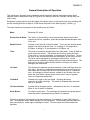
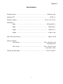
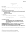
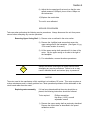
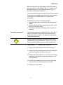
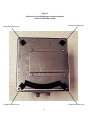
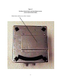
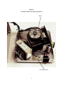
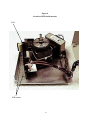
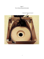
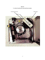
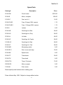
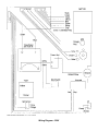
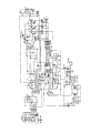
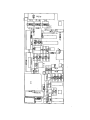
SERVICE MANUAL
for
LABNET
SPECTRAFUGE 16M
MICROCENTRIFUGE
Contents
Section 1
General Description of Operation ............................................................ 1
Specifications ........................................................................................... 2
Section 2
Warranty Information ............................................................................... 3
Section 3
Troubleshooting ....................................................................................... 4
Section 4
Service Instructions ................................................................................. 5
Maintenance ................................................................................. 5
Cleaning and lubrication
Removing the rotor
Maintaining the rotor
Rotor screw
Speed Calibration
Service Procedures ...................................................................... 7
Removing housing and lid assembly
Motor
Replacing the motor
Printed circuit board
Verifying connections
Replacing the PCB
Miscellaneous components
Timer and momentary switch
Lid latch mechanism
Braking transformer
Section 5
Illustrations ............................................................................................ 11
Section 6
Spare Parts List ..................................................................................... 19
Section 7
Schematics and Drawings ..................................................................... 20
Section 1
General Description of Operation
This centrifuge is generally used in biological and biochemical research laboratories where small
samples must be subjected to high RCF (g-force) for relatively short time intervals (usually thirty minutes or less).
Designed to accept popular micro-test tubes with captive caps in a high speed rotor, this centrifuge will
provide centrifugal forces as high as 16,000 times the power of the earth's gravity (16,000 x g)*
The major functional components of the centrifuge are as follows:
Motor
Brushless DC motor.
Printed Circuit Board
The "brain" of the centrifuge, the microprocessor based circuit board
controls the lid lock, operation, speed and acceleration/deceleration rates
of the unit.
Speed Control
Located on the left side of the front panel. Turn to set the desired speed.
Speed is set directly with this knob, i.e. a setting of 4 corresponds to
4,000rpm, a setting of 10 corresponds to 10,000rpm, etc.
Timer
This knob is located on the right side of the front panel. It acts as both an
on/off switch and a timer. The desired time is set by turning the knob.
Time is set in 1 minute increments, to a maximum of 30 minutes. Turning
the knob to the zero position starts the deceleration of the rotor to a stop.
The timer can be bypassed by pressing the quick button. A hold
position can be actuated by rotating the timer knob counterclockwise. The
knob may be turned in either direction before or during a run without
damaging the mechanism.
Lid Latch
This electronic mechanism prevents operation of the centrifuge when the
lid is open. Driven by a solenoid and controlled by the circuit board, this
latch keeps the lid locked until the rotor has almost come to a complete
stop. An emergency lid latch release, located in the left side of the unit
below the quick button, allows access to the rotor in case of a power
failure or component malfunction.
Lid Switch
Located to the right of the front panel. Pressing this button
opens the lid of the centrifuge. This switch is disabled while the centrifuge is in operation.
Lid Lock Indicator
Located above the speed control. Indicates that the unit is in operation.
When lit, the lid switch is disabled.
Quick Button
For short or quick spins. The centrifuge will operate at the preset speed
while this button is pressed and stop when it is released.
*Rotational speeds of this magnitude can be converted to "rim speeds" of nearly 300 miles per
hour. Use extreme caution when working with this equipment. The technician should inspect the
rotor periodically for visible signs of damage or stress. The rotor screw should be checked for
tightness.
1
Section 1
Specifications
Maximum speed ............................................................................................... 14,000 rpm ±5%
.
Maximum RCF .......................................................................................................... 16,000 x g
Maximum capacity ....................................................................................... 36 mL (18 x 2.0 mL)
Dimensions
Width .............................................................................................. 209.5mm/8.25 in.
Depth ................................................................................................... 226mm/8.9 in.
Height .................................................................................................. 193mm/7.6 in.
Weight ................................................................................................. 5.1kg/11.2 lbs.
Noise level (with full rotor) .................................................................................... Approx. 56 dB
Electrical Ratings
120V Version ......................................................................... 120V~, 50-60 Hz, 1.0A
Fuse 250V,2.5AT
230V Version ......................................................................... 230V~, 50-60 Hz, 0.5A
Fuse 250V, 1.25AT
Ambient operating range ............................................................................... +2.0ºC to +40.0ºC
2
Section 2
Warranty Information
Limited Warranty
This warranty is valid in U.S.A. only
Repair or Replacement
The manufacturer warrants this equipment to be free of defects in material and workmanship for a period of 12 months from the
original date of purchase. This warranty includes labor and parts, and excludes damage caused by abuse or neglect.
If defects occur during the warranty period, the manufacturer will, at its option, repair or replace the product. Proof of purchase is
required.
In-Warranty Service
We will provide warranty service if you bring to our attention, within 12 months from date of original purchase, a defect covered by the
warranty. To obtain warranty service, you must do the following:
1) Call the Customer Service number, printed below, to arrange for warranty service. The Customer Service Representative will
give you a Return Authorization Number (RAN):
Customer Service 732 417-0700
Hours of operation: 8:30 am to 5:00pm, Eastern Standard Time
Monday through Friday (excluding holidays)
2)
Shipping instructions:
Pack the unit in its original packaging or a protective carton, padded to avoid damage. UPS is the preferred shipper.
Labnet will not be responsible for damage resulting from improper packaging.
Send package postage prepaid
Include the following:
and insured to:
a) All accessories originally included, unless otherwise instructed
National Labnet Company
b) A copy of your proof of purchase
162 Fernwood Ave
c) Your name and shipping address
Edison, NJ 08837
d) Name and phone number of contact person
(no collect shipments accepted)
e) A brief written description of the problem
Exclusions and Limitations
This warranty does not cover the following:
a) Damage caused by transit or improper packaging
b) Damage caused by accident, misuse, negligence, improper installation or maintenance, improper
operation, damage resulting from dirt, water, lightening or other natural forces.
c) Damage caused by tampering, alteration or repair performed or attempted by anyone other than the
manufacturer or its authorized repair agent
d) Damage to the finish or paint
Legal Rights and Limitation of Liability
ALL WARRANTIES, INCLUDING THE IMPLIED WARRANTY OF MERCHANTABILITY AND THE IMPLIED WARRANTY OF
FITNESS FOR A PARTICULAR PURPOSE ARE LIMITED IN DURATION TO 12 MONTHS FROM THE DATE OF ORIGINAL
PURCHASE. REPAIR OR REPLACEMENT IS PROVIDED AS THE SOLE AND EXCLUSIVE REMEDY.
NATIONAL LABNET COMPANY IS NOT LIABLE FOR INCIDENTAL OR CONSEQUENTIAL DAMAGE, COMMERCIAL LOSS, OR
ANY OTHER LOSS OR DAMAGE NOT SPECIFIED IN THIS WARRANTY.
Some states do not allow limitations on the length of implied warranties, or exclusions of limitation of incidental or consequential
damages. The above limitations or exclusions may not apply to you. This warranty gives you specific rights. You may have other
rights which vary from state to state.
No individual has the authority to extend this warranty period. No individual can accept for or on behalf of the manufacturer, any other
obligation of liability in connection with the sale of this equipment.
This warranty is valid only in the United States of America and only for the original purchaser.
For out of warranty service, call our Customer Service Department for information: 732 417-0700.
3
Section 3
Troubleshooting
Problem
Possible cause
Solution
Lid will not open
(with power/rotation light on).
Rotor still turning.
Wait for rotor to stop.
Internal electrical failure.
Requires service.
No power supply.
Check plug connection on back of unit.
No power supply.
Check/replace fuse.
No power supply.
Check wall outlet.
Internal failure.
Requires service.
Debris lodged inside rotor.
Disassemble and clean out rotor.
Rotor improperly loaded.
Load symmetrically/balance tubes.
Rotor damaged.
Requires service or replacement.
Centrifuge not on firm, level surface.
Relocate to appropriate surface.
Motor damaged.
Requires service.
Lid not properly closed.
Press down firmly on front of lid.
Timer not set.
Select a timer interval.
Speed not set.
Select a speed from 1,000 to 14,000rpm.
No power supply.
Check plug connection on back of unit.
No power supply.
Check/replace fuse.
No power supply.
Check wall outlet.
Rotor screw is not tight on motor shaft.
Tighten rotor screw as firmly as possible
by hand. Then tighten an additional 1/8
turn using a wrench or other appropriate
tool. Do not exceed 1/8 turn.
Bottom shield of rotor is not properly
secured to top part of rotor.
Check and tighten the three screws on
bottom of rotor assembly.
Whistling noise (high-pitched) during
acceleration or deceleration.
Rotor cover is off and rotor is less than
1/3 full.
Add extra tubes symmetrically and/or
install rotor cover.
Power/rotation light does not illuminate.
Defective fuse.
Check/replace fuse.
Excessively noisy while rotating at
maximum speed.
Rotor is poorly balanced.
Check with a well balanced load.
Rotation is too fast.
Recalibrate speed.
Failure of electronic braking circuit.
Requires service.
Lid will not open
(with power/rotation light off).
Excessive vibration.
Rotor does not rotate.
Grinding or metallic rattle noise during
acceleration or braking.
Rotation light stays on after rotor has
stopped.
4
Section 4
Service Instructions
MAINTENANCE
Beginning after the first 300 hours of use, and periodically thereafter, a qualified electronics technician
should inspect the centrifuge.
Cleaning & Lubrication
CAUTION
Removing the rotor
The rotor, rotor chamber and centrifuge casing must be kept
clean. Using a cloth damp with water or mild detergent, the
casing and chamber should be wiped clean and kept in "likenew" condition. Clean all spills immediately, removing the
rotor for best results. No routine lubrication is necessary.
Disconnect from power source before any cleaning procedure. No flammables or solvents are to be used, especially
in the presence of electrical power or in a recently used (still
warm) centrifuge.
1) Using an adjustable or 1/4 inch wrench, loosen the rotor
screw and remove the rotor retaining screw/washer
assembly by turning it counter-clockwise.
2) Lift the rotor straight up and out of the chamber.
3) To reinstall the rotor, reverse the above procedure. Be
sure the cross pin on shaft lines up with slot on underside of rotor.
Maintaining the rotor
CAUTION
The rotor must be checked periodically (every 12 months or
more often if required) for signs of wear, damage or misuse.
Corrosive materials must be promptly cleaned and thoroughly removed. For best results, disassemble the rotor by
removing the 3 screws at the bottom and pulling the upper
and lower components apart. The rotor must be reassembled in the same orientation. The rotor can be autoclaved or wiped with radioactive decontaminant only when
disassembled. It should not be soaked in decontaminant.
When reassembling the rotor, be sure to return the upper
and lower sections to their original orientation. Misalignment
could result in a moderate imbalance and increased vibration during high and low speed operation. The three screws
must be tightened firmly.
Any cracks, deep scratches, stress marks or other damage
to the rotor should be reported immediately. Any rotor
exhibiting any of the above indicators must be removed from
service immediately. Failure to do so may result in injury.
5
Section 4
Rotor screw
The rotor screw must be kept tight enough that it cannot be
removed by hand. If it has become loose, tighten it firmly,
clockwise, by hand and subsequently torque an additional
1/8 turn using a wrench or other appropriate tool.
Speed calibration
After every 100 hours of use (or more frequently if required
by other agencies) the maximum rotor speed should be
verified using an external tachometer via the below procedure or another procedure as required by regulatory agencies. Speed calibration must be performed if the motor or
circuit board has been replaced.
Tools required:
insulated screwdriver, non-conductive
photo electric tachometer
reflective adhesive contrast dot/tape
1) Remove metal chute (4 phillips screws) from bottom of
unit. (See figure #3, pg 13.) This will expose a figure 8
shaped hole through which the speed adjust pots can
be accessed. The rear-most is the high speed adjustment pot and the front-most is the low speed adjustment pot.
2) Elevate the unit in a normal upright operating position
so that the adjusting pots can be accessed.
Speed pot access
3) Install a small dot of reflective tape near the top outer
edge of the rotor lid catch. Set the speed control on the
front panel at maximum (#14), close the lid and turn on
the unit using the timer.
4) Set up the tachometer through the clear window in the
centrifuge lid to monitor rotor speed. Adjust the high
speed pot (rear-most) so that the rotor speed measures
approximately 14,000rpm on the tachometer.
5) Run the unit at this speed for a minimum of 5 minutes.
6) Adjust the high speed pot (rear-most) so that the rotor
speed measures 14,000rpm, plus or minus 150rpm on
the tachometer.
7) Rotate front panel speed control to #1 (1,000rpm)
setting. Adjust low speed pot (front-most) so that the
rotor speed measures approximately 1,000rpm.
8) Run the unit at this speed for a minimum of 5 minutes.
6
Section 4
9) Adjust the low speed pot (front-most) so that the rotor
speed measures 1,000rpm, plus or minus 100rpm on
the tachometer.
10) Replace the metal chute
The unit is now calibrated.
SERVICE PROCEDURES
Take care when performing the following service procedures. Always disconnect the unit from power
source before attempting any service operations.
Removing Upper Casing Shell 1) Remove rotor as outlined in the rotor section.
2) Remove the 4 phillips head screws that secure the
upper casing shell to the baseplate. (See figure #1, pg
12 for exact location of screws.)
3) Lift the upper casing shell upward until it is clear of the
motor. Lay the upper casing on its side to the right of
the baseplate.
5) For reinstallation, reverse the above procedures.
CAUTION
Always disconnect centrifuge from power source before
attempting any service procedures. Failure to do so may
result in electrical shock and serious injury to personnel.
MOTOR
The motor used in the manufacture of this centrifuge is a brushless, DC motor. This motor requires no
routine maintenance and is virtually problem free. Most operational problems will be attributable to the
circuit board rather than the motor.
Replacing motor assembly
If it has been determined that the motor should be replaced, the following instructions should be followed.
Tools required:
Phillips screwdriver
Nut driver (11/32") or small
adjustable wrench
1) Remove the upper casing shell as previously described.
Remove the metal chute as described in the speed
calibration section.
7
Section 4
2) Unplug the motor connection from the PCB.
3) Loosen the ground nut and remove the motor ground
lead (figure #4, pg 14).
4) Remove the 4 motor nuts on the bottom of the baseplate (figure #5, pg 15). Remove motor assembly and 4
star washers under the isolators from unit, noting the
orientation and routing of motor and ground leads.
5) Install new motor assembly (with star washers on
isolator studs) in chassis in the same orientation as the
old motor. Attach and tighten the 4 motor nuts on the
bottom of the unit. Be sure the isolators are not twisted.
6) Plug the motor connector into the PCB and attach
ground lead under ground nut and tighten securely.
7) Make sure air channels are installed down against
foam.
8) Reinstall upper casing shell and tighten screws securely.
9) Calibrate speed as previously described on page 6.
10) After calibration, reinstall metal chute.
Speed must be recalibrated after replacing the motor.
Failure to do so may result in serious injury.
CAUTION
PRINTED CIRCUIT BOARD (PCB)
The majority of failures that cannot be attributed to the motor can be traced to printed circuit board
component failure. If the fault has been isolated to the PCB, it is recommended that a new board be
installed. For those who prefer to troubleshoot to the component level, board diagrams are provided in
Section 7.
Verifying Connections
All of the various centrifuge components are connected to
the PCB. Depending upon the nature of the fault, the
technician should verify that these connections are secure,
while the unit is disconnected from the power source.
Replacing the PCB
Tools required:
Phillips screwdriver
1) Remove the upper casing shell as previously described.
8
Section 4
2) From the bottom of the unit, remove the 2 PCB mounting screws and nuts that secure the PCB brackets to
the baseplate (see figure #6, pg 16).
3) One at a time, remove each of the 3 plug in connectors
from the old PCB and install into the same location on
the new PCB.
4) Position the new PCB so that the 2 mounting bracket
holes are aligned with the two baseplate holes and
reinstall the 2 PCB mounting screws and nuts.
5) Replace the upper casing shell as previously described.
Tighten the 4 screws securely.
6) After reassembling the unit and reinstalling the rotor, the
speed must be calibrated according to the instructions
in the "Speed Calibration" section.
CAUTION
Speed must be recalibrated after replacing the PCB. Failure to do so may result in serious injury.
MISCELLANEOUS COMPONENTS
Timer & Momentary Switch
If the unit will not rotate when the timer is turned on, press
the momentary switch. If the unit still does not rotate, the
problem is not attributable to the timer or momentary
switch. However, due to the fact that both switches are
used for identical internal switching, a quick diagnosis is
easy to perform. Any time that one of these two controls is
operational and the other is not, the latter control is either
the victim of a short circuit connection, or is defective and
should be replaced.
Lid Latch Mechanism
The lid latch is disengaged by a DC solenoid and is essential to proper operation. For safety reasons, no attempt
should be made to modify, tamper with or defeat the latch
mechanism. To actuate the lid latch release, depress the
"lid" button on the front panel. The release can only be
actuated when the lid is completely closed and latched and
the rotor is not turning. The technician should be aware of
the interaction between these components at all times
during the troubleshooting process.
In the event that the lid latch mechanism will not energize,
power to the solenoid should be verified. To access the
entire latch assembly, remove the upper casing shell as
previously described.
9
Section 4
After removing, turn the upper casing so that the inside of
the front panel is visible (figure #7, pg 17). If power to the
solenoid is present, but the solenoid does not move, it
should be checked and/or replaced.
Other potential latch faults could be the result of poor wiring
connections, poor alignment of the lid latch catch, sticking
or jamming of the lid latch strike or no contact at the
microswitch.
If necessary the lid may be opened manually:
1. Disconnect the power cord from the wall socket power
supply.
2. Remove the plastic plug, located on the left side of the
unit, below the quick button.
3. Pull the cord (attached to the plug) to open the lid lock
manually.
Stepdown Transformer
CAUTION
The stepdown transformer supplies 24 VAC to the PCB. If
power is not present, check the primary and secondary
windings for opens or shorts. To replace the transformer,
follow these instructions.
Always disconnect centrifuge from power source before
attempting any service procedures. Failure to do so may
result in electrical shock and serious injury to personnel.
Tools needed:
Phillips head screwdriver
1) Remove the outer casing as previously described.
2) Remove the two mounting screws and nuts holding the
transformer in place (see figure #8, pg 18).
3) Remove the wire connectors one at a time from the old
transformer and transfer to the same positions on the
new transformer.
4) Line the new transformer up over the mounting holes
and secure the two mounting screws and nuts.
5) Replace the outer casing.
10
Section 5
Illustrations
Figure 1
Spectrafuge 16M
Tach window
Lid
Upper
casing
Lid
switch
Timer
Quick
button
Speed control
Lid lock indicator
11
Figure 2
Position of screws holding upper casing to baseplate
(shown from bottom of unit)
Casing-baseplate screw
Casing-baseplate screw
Casing-baseplate screw
Casing-baseplate screw
12
Figure 3
Position of metal chute and attachment screws
(view from bottom of unit)
Metal chute with screws at the 4 corners
13
Figure 4
Location of motor and motor ground nut
Motor
Motor ground nut
14
Figure 5
Location of nuts holding motor in place
(bottom view of unit)
Motor nuts
15
Figure 6
Location of PCB and its mounts
PCB
PCB mounts
16
Figure 7
View of front control panel electronics
Underside of front control panel
17
Figure 8
Location of transformer and transformer mounts
Transformer mounts
Transformer
18
Section 6
Spare Parts
Catalog #
Description
Price
C0160-CB
Circuit board
$270.00
C0160-E
Motor, complete
C-0160-F
Feet, set of 4
C0160-FUSE
Fuse, 2.5amp (120V version)
1.75
C0160-FUSE1
Fuse, 1.25amp (230V version)
1.75
C0160-I
Isolator
3.00
C0160-LB
Centrifuge lid, Blue
80.00
C0160-LG
Centrifuge lid, Grey
80.00
C0160-LL
Lid latch
48.00
C0160-LP
Centrifuge lid, Purple
80.00
C-0160-LR
Centrifuge lid, Red
80.00
C0160-LT
Centrifuge lid, Teal
80.00
C0160-MS
Momentary switch
C0160-RC1
Rotor cover and clasp
C0160-SK
Speed knob
6.00
C0160-TF
Transformer
50.00
C0160-TK
Timer knob
6.00
C0230-T30
Timer, 30 minute
C02300-P2
Motor crosspin
3.00
C1236-M
Rotor screw
3.00
295.00
12.00
Please specify serial number when ordering parts.
Prices effective May 1999. Subject to change without notice.
19
6.00
30.00
73.00
Section 7
Schematics and drawings
This page intentionally left blank
20
Wiring Diagram - 120V
Wiring Diagram - 230V
Control Board Reference
Reference
C1, C9, C19, C20
C2, C4, C6, C7, C8, C10, C18
C3, C14, C16, C17
C5
C11
C12
C13
C15
C21
CAP1, CAP2
CLIM1
CR1, CR2, CR3
CR4
CR5, CR6, CR7, CR8, CR9, CR10, CR11, CR12, CR13
D1
F1
IEC INPUT CONN1
L1
LED1
LID SAFTY SW1
LID SW1
MOTOR1, PANEL1, POWER1
PULSE1
Q1
Q2, Q3, Q4, Q5, Q6, Q10
Q7
Q8, Q9
R1, R19, R29
R2
R3, R4, R9, R11
R5
R6
R7, R26, R28
R8
R10
R12
R13
R14, R24
R15
R16, R17
R18
R20, R30
R21
R22
R23
R25
R27
R31
R32
R33
RP1
RP2
RP3
RP4
Part
NIC NRSA 100 M 35V 5X11 TR
NIC NCMA10 Z5U 103 M 100 TR
NIC NCMA30 Z5U 105 M 50 TR
NIC NCMA20 Z5U 104 M 50 TR
NIC NRSA 222 50V 18X36 TR
NIC NRSA 101 50V 8X11.5 TR
NIC NRSA 330 35V 5X11 TR
CAP NOT NEEDED
NIC NRM 105 K 100
EXT
MELEXIS US5881UA NONLATCHED HALL SENSOR
P6KE15CA
1N5240B
DIODE UF4002
GBPC2501W
REAR PANEL FUSE 2 AMP
REAR PANEL LINE CONN.
5 TURNS ON TORROID
FRONT PANEL LED
LID SAFTY SW.
FRONT PANEL LID OPEN SW.
MOLEX 26-48-1086
FRONT PANEL PULSE SW.
2N7000
IRFZ46n
TECOR S2015L
IRFZ34N
4.7K 1/4W 5%
470 OHM 1/4W 5%
10K 1/4W 5%
390 OHM 1/4W 5%
47K 1/4W 5%
100K 1/4W 5%
1MEG 1/4W 5%
2.2 MEG 1/4W 5%
39K 1/4W 5%
NOT USED
1.5K 1/4W 5%
1K 1/4W 5%
3006P-102 BOURNS
180K 1/4W 5%
3.3K 1/4W 5%
2K 1/4W 5%
200 OHM 1/4W 5%
820 OHM 1/4W 5%
1 OHM 10W 5%
68K 1/4W 5%
82 OHM 1/4W 5%
82 OHM 1/4W 5%
130 OHM 1W
BUSSBOURNS 4605-101-102
BOURNS 4604-101-103
BOURNS 4606-102-681
BOURNS 4604-101-272
Control Board Reference - continued
Reference
SAFTY1
SOLENOID1
SPEED1
T1
TIMER1
U1
U2
U3
U4
U5
U6
U7
U8
U9
WH1, WH2, WH3, WH4
Part
HEADER 4 PIN NOT USED
LID OPEN SOLENOID 24 VAC
FRONT PANEL POT 100K
TRANSFORMER
FRONT PANEL TIMER SW.
ATF16V8BQL-25PC
LM7815T
LM339CN
LM7805T
ULN2003N
LM555CN
MOC3010
MAX954EPA
CD4093BCN
PAD