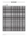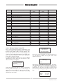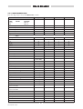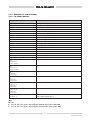
1
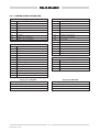
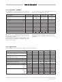
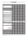
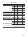
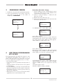
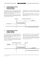
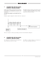
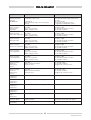
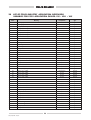
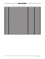
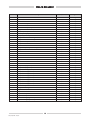
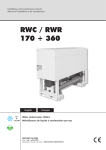
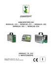
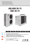
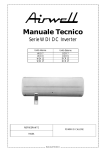
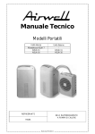
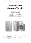
Chiller unit
VLS-VLH-VLC
R 410 A
VLS-VLH-VLC CHILLER - 4 COMPRESSORS
1
GENERAL INFORMATION
1.1
INTRODUCTION
2.1
2.1.1 GENERAL INFORMATION
The figure shows the terminal with the front door open.
It is provided with a LCD 4 lines x 20 columns, keyboard and microprocessor-controlled LED's, so as to
allow the programming of the control parameters (setpoint, differential bands, alarm thresholds) and the
main operations to be carried out by the user.
This document contains the information and the operating instructions for VLS-VLH-VLC 4 compressors & electronic control.
This information is for the after-sales service and the
production operators, for the end-of-line testing.
1.2
MAIN CHARACTERISTICS
– Microprocessor control
– User-friendly keyboard
– Proportional and integral control of the return water
temperature (RWT)
– Hysteresis control of the leaving water temperature
(LWT)
– Access code to enter the Manufacturer's Level
– Access code to enter the Assistance Level
– Alarm buzzer and LED
– Backlighted LCD
– Closed-loop condensing pressure control
– Pump-Down logic (start-stop)
– Rotation of the compressor operation
– Oil return function
– Night mode (or Low Noise) control
– Counting of the pump/compressors' hours of operation
– Display of discharge pressure values
– History of stored alarms (option)
– Programming of different setpoints with 4 ranges of
time/setpoint.
The following accessories can be also connected:
– Real Time Clock Memory Card: alarm history and
programming of different setpoints with ranges of
time
– Serial Communication RS485 Card; to connect the
Chiller Control to a BMS network
– Remote Display Terminal
– Wire Remote Control
– Phase monitor kit
2
KEYBOARD & DISPLAY TERMINAL
2.1.2 TERMINAL & KEY BOARD DESCRIPTION
The terminal makes it possible to carry out the following
operations:
– the initial configuration of the machine
– the change of all the main operating parameters
– the display of the detected alarms and their acoustic
signalling by a “buzzer”
– the display of all the measured quantities
The terminal and the card are connected by a 6-way
phone cable.
The connection of the terminal to the basic card is not
essential for the normal operation of the controller.
CONTROL OF VLS-VLH-VLC
WITH 4 COMPRESSORS
THE CHILLER CONTROL SYSTEM
The VLS-VLH machines with 4 scroll compressors are
provided with a microprocessor card which is fully programmed by default for the control of a chiller of cold
only type with 2 circuits, 2 compressors per circuit, a
high-pressure transducer per circuit. The control system
consists of:
2
VLS/VLH/VLC 10/06
2.2
Access to the “display mask” of the machine
status.
DISPLAY
Utente
Costruttore
Manutenzione
In/Out
Setpoint
Versione
Fasce orarie
Esc key: allows you to move from one mask to
another.
The display is an LCD 4 lines x 20 columns. The quantities and the information about the operation of the unit
are alternated in the form of subsequent screens,
named.
Alarm key: used to display the alarms, to reset
them in manual
Press it one to display the mask of the activated alarm, press it again to reset the alarm
signal.
+
+
x
Home
Prg-Esc keys: Pressing these keys at the
same time,allows you to turn the unit
on/off.
+
Up-Down keys: allows you to set the
control parameters' values and to move
from one mask to another (not backlighted).
2.3
Riga0
Riga1
Riga2
Riga3
+
KEYBOARD
2.3.1 ARROWS KEY - UP/DOWN/ENTER
If the cursor is in the top left-hand corner (Home), press
the UP/DOWN keys to access the subsequent masks
associated to the selected branch. If a mask includes
some value setting fields and you press the ENTER key,
the cursor will reach these fields.
Once you have reached the quantity setting field, you
can modify any value (within the expected limits) by
pressing the UP/DOWN keys.
After you have selected the desired value, press the
ENTER key again to store it.
Enter key: used to move the cursor inside the
masks and to save the values of the set parameters.
Alarm-Enter keys:Press these keys at the
same time to enter the "storical alarm“
after 1’ come back at status machine
menu’.
3
VLS/VLH/VLC 10/06
2.3.2 ALARMS
Code
AL00
Alarm unit description
Automatic alarm
Comp
Status
on
Ventil.
Status
on
Pump
Status
on
Aut/Man
Reset
Aut
Delay
Notes
0
AL01
Efficiency alarm CPS
Off
Off
Off
Man
30 sec
AL02
Flow meter alarm
Off
Off
Off
Man
Parameter
AL03
Sys 1 High pressure “manual reset”
Off Sys 1
Run
Run
Man
No
AL04
Sys 2 High pressure “manual reset”
Off Sys 2
Run
Run
Man
No
AL07
Failure of sensor B3 Sys 1 DP1
Run
Max
Run
Auto
10 sec
AL08
Failure of sensor B4 Sys 2 DP2
Run
Max
Run
Auto
10 sec
AL09
Failure of sensor B5 Tair
Run
Max
Run
Auto
10 sec
AL10
Failure of sensor B6 T LAN
Off
Off
Run
Auto
10 sec
AL11
Failure of sensor B7 Tin
Off
Off
Run
Auto
10 sec
AL.12
Failure of sensor B8 Tout
Off
Off
Run
Auto
10 sec
AL13
Failure of sensor B1 Tcoil1
Run
Run
Run
Auto
10 sec
defrost
every 40’
AL14
Failure of sensor B2 Tcoil2
Run
Run
Run
Auto
10 sec
defrost
every 40’
AL15
Failure of sensor B3 TANDEM 1
Run
Max
Run
Auto
10 sec
AL16
Failure of sensor B4 TANDEM 2
Run
Max
Run
Auto
10 sec
AL17
Maintenance of compressor 1
Run
Run
Run
Man
No
AL18
Maintenance of compressor 2
Run
Run
Run
Man
No
AL19
Maintenance of compressor 3
Run
Run
Run
Man
No
AL20
Maintenance of compressor 4
Run
Run
Run
Man
No
AL21
Pump maintenance alarm
Off
Off
Off
Man
No
AL22
Failure of clock card
Run
Run
Run
Man
No
AL23
Thermal switch, compressor 1
Off Comp. 1
Run
Run
Man
No
AL23A
Thermal switch, compressor 1
Off Comp. 1
Run
Run
Auto
1 time auto VLS
3 time auto VLH
AL24
Thermal switch, compressor 2
Off Comp. 2
Run
Run
Man
No
AL24A
Thermal switch, compressor 2
Off Comp. 2
Run
Run
Auto
1 time auto VLS
3 time auto VLH
AL25
Thermal switch, compressor 3
Off Comp. 3
Run
Run
Man
No
AL25A
Thermal switch, compressor 3
Off Comp. 3
Run
Run
Auto
1 time auto VLS
3 time auto VLH
AL26
Thermal switch, compressor 4
Off Comp. 4
Run
Run
Man
No
AL26A
Thermal switch, compressor 4
Off Comp. 4
Run
Run
Auto
1 time auto VLS
3 time auto VLH
AL27
Sys 1 Low pressure
Off Sys 1
Run
Run
Man
Parameter
AL27A
Sys 1 Low pressure
Off Sys 1
Run
Run
Auto
3 time auto
AL28
Sys 2 Low pressure
Off Sys 2
Run
Run
Man
Parameter
AL28A
Sys 2 Low pressure
Off Sys 2
Run
Run
Auto
3 time auto
AL29
Thermal switch, fans
Off
Off
Run
Man
No
AL29A
Thermal switch, fans A
Off
Off
Run
Auto
1 time auto
AL30
Sys 1 Antifreeze alarm
Off Sys 1
Off
Run
Man
No
AL30A
Sys 1 Antifreeze alarm
Off Sys 1
Off
Run
Auto
1 time auto
AL32
Espansion off line
Run
Run
Run
Auto
No
AL33
Eprom failure
Off
Off
Off
Man
No
4
VLS/VLH/VLC 10/06
Code
Alarm driver description
CIRC 1 - EEV 1
Status
CIRC 2 - EEV 2
Status
Notes
AL34
Eprom failure driver 1
Off
Run
Man
AL35
Eprom failure driver 2
Run
Off
Man
AL36
Cable motor EVV driver 1
Off
On
Man
AL37
Cable motor EVV driver 2
On
Off
Man
AL38
Timeout MOP driver 1
0%
–
Auto
AL39
Timeout MOP driver 2
–
0%
Auto
AL40
Timeout LOP driver 1
100%
–
Auto
AL41
Timeout LOP driver 2
–
100%
Auto
AL42
Low SH driver 1
Run
Run
Auto
AL43
Low SH driver 2
Run
Run
Auto
AL44
Valve open driver 1
Off
Run
Auto
AL45
Valve open driver 2
Run
Off
Auto
AL46
High SH driver 1
Run
Run
Auto
AL47
High SH driver 2
Run
Run
Auto
AL48
Sensor 1 driver 1
Off
Run
Auto
AL49
Sensor 1 driver 2
Run
Off
Auto
AL50
Sensor 2 driver 1
Off
Run
Auto
AL51
Sensor 2 driver 2
Run
Off
Auto
AL52
Sensor 3 driver 1
Off
Run
Auto
AL53
Sensor 3 driver 2
Run
Off
Auto
AL54
GaAhead driver 1
Run
Run
Auto
AL55
GaAhead driver 2
Run
Run
Auto
AL56
Lan driver 1 disconnected
Off
Run
Auto
AL57
Lan driver 2 disconnected
Run
Off
Auto
AL58
Auto set up driver 1
Off
Run
Auto
AL59
Auto set up driver 2
Run
Off
Auto
2.3.3 Advanced alarm history file
DISPLAY LOG DATA
Which memory?
This is a special function that can be enabled by using
a memory expansion board and from a list of variables
that has been loaded together with the software. This
function will enable the user to record and display some
readouts of pre-established parameters at regular intervals or to download the file on a Pc and to display the
history file in the Excel format.
To display the advanced history file, press the Alarm
and Enter keys at the same time until the mask of the
advanced history file appears.
EXPANSION MEMORY
Here below select the Log file you wish to display since
you can have more than one Log file on the same
expansion memory.
DISPLAY LOG DAT
Which Log?
Log01.
>SYSTEM INFORMATION
LOG DATA
OTHER INFORMATION
–
After having selected the Log file you wish, the following mask will require you to select the record you wish
to display. The latest record will be displayed by
default, but you can select an earlier record by using
the arrow keys and by pressing the Enter key to confirm.
Select the Log Data item and press Enter to confirm. The
following mask will require you to select the type of
memory you wish to access, i.e. the internal one or the
additional one. The additional memory is selected by
default. Then press Enter.
3 06-06-06
UP
:
DOWN
:
ENTER
:
15:50:16
next record
prev. record
view data
5
VLS/VLH/VLC 10/06
2.3.4 MAINTENANCE LEVEL
Press the “Prg” key to access the Maintenance” masks:
Parameter
Type
Min. Value
Max. Value
Default
T in
°C
-3
3
0
T out
°C
-3
3
0
T P Lan
°C
-3
3
0
T coil 1
°C
-3
3
0
T coil 2
°C
-3
3
0
DP 1
bar
-3
3
0
DP 2
bar
-3
3
0
T.tandem Sys 1
°C
-3
3
0
T.tandem Sys 2
°C
-3
3
0
N (Hours
(010x1000)
0
100
10
Pump
flag
N=NO
Y=YES
N
Compressors
flag
N=NO
Y=YES
N
EEV Modality
flag
AUTO
MAN
AUTO
Step
flag
0
2625
EEV position
flag
0
2625
EEV Modality
flag
AUTO
MAN
Step
flag
0
2625
EEV position
flag
0
2625
S1
bar
-3
3
0
S3
°C
-3
3
0
S1
bar
-3
3
0
S3
°C
-3
3
0
AL 000
Setpoint
RWT
N° 0000
h 00:00
00/00/00
00,0 °C
00,0 °C
SYS 1 – comp. 1.
000000 h
SYS 1 – comp. 2.
000000 h
SYS 2 – comp. 1.
000000 h
SYS 2 – comp. 2.
000000 h
Pump
000000 h
Insert the password
0000
Offset probe
Maintenance
Alarm threshold
Reset hours
Disabile compressors
Driver 1 Manual manAge
Driver 2 Manual manAge
AUTO
Driver 1 status
Nessuna anomalia
Driver 2 status
Nessuna anomalia
Offset probe driver 1
Offset probe driver 2
6
VLS/VLH/VLC 10/06
2.3.5 PRINTING KEY (NO AVAILABLE)
2.3.6 I/O (INPUT/OUTPUT)
Acronym
Description
Tin
Entering water temperature
Tout
Leaving water temperature
TPLAN
Water temperature plant (Option)
Tair
External air temperature
Tcoil #1
Sensor coil SYS 1 (only HP)
Tcoil #2
Sensor coil SYS 2 (only HP)
DP minore (see note)
DP #1
Sys 1: discharge pressure transducer
DP #2
Sys 2: discharge pressure transducer
INVERTER FAN %
% FAN SPEED
TEMPERATURE TANDEM SYS #1
Discharge temp tandem sys1
TEMPERATURE TANDEM SYS #2
Discharge temp tandem sys2
DIGITAL INPUT
Input del pCO1
DIGITAL INPUT EXPANSION
Input expansion
DIGITAL OUPUT
ANALOG OUTPUT
FAN INVERTER
0-10V to the FSC
Threshold alarm high SH
Driver 1 Cool
EEV
Valve position
Power required
EEV circuit 1 Status
Driver 2 Cool
EEV
Valve position
Power required
EEV circuit 2 Status
Driver 1
SH
Evap.temp
Suction temp.
Circuit 1 SH value
Driver 2
SH
Evap.temp
Suction temp.
Circuit 2 SH value
Driver 1
Evap.pressure
Evap.temp
Suction temp.
Drive value circuit 1
Driver 2
Evap.pressure
Evap.temp
Suction temp.
Drive value circuit 2
Ver. Driver 1
SOFT WARE VERSION EEV 1
Ver. Driver 2
SOFT WARE VERSION EEV 2
(Note)
DP roule
IF Tair < 0 °C the fan speed % depend by the minimum value between DP1- DP2
IF Tair > 0 °C the fan speed % depend by the maximum value between DP1- DP2
7
VLS/VLH/VLC 10/06
2.3.7 ANALOG/DIGITAL DESCRIPTION
Analog input pCO1
Digital input pCO1
n°
Description
n°
Description
B1
Low pressure transducer #1
ID1
Remote On/Off
B2
Low pressure transducer #2
ID2
Cool/Heat
B3
High pressure transducer #1
ID3
Fan thermal
B4
High pressure transducer #2
ID4
Compressor thermal #1
B5
Air temperature
ID5
Compressor thermal #2
B6
T pLAN
ID6
Compressor thermal #3
B7
Water inlet temperature
ID7
Compressor thermal #4
B8
Outlet water temperature
ID8
Flow switch
ID9
Step 1
ID10
Step 2
Description
ID11
Step 3
NO1
Compressor #1 circuit #1
ID12
Step 4
NO2
Compressor #2 circuit #1
ID13H
High pressure switch # 1 (230V)
NO3
Solenoid liquid valve circuit #1
ID14H
High pressure switch # 2 (230V)
NO4
Compressor #1 circuit #2
NO5
Compressor #2 circuit #2
NO6
Solenoid liquid valve circuit #2
n°
Description
NO7
Antifreezing heater
Y1
Inverter fan
NO8
Reversing valve
Y2
NO9
Fan step 1
Y3
NO10
Fan step 2
Y4
NO11
Pump
NO12
Alarm circuit # 1
NO13
Alarm circuit # 2
Digital output pCO1
n°
Analog output pCO1
Analog input t LAN pCOE
Digital input PCOE t LAN
B1
Defrost temperature #1
ID1
High temperature tandem. 1
B2
Defrost temperature #2
ID2
High temperature tandem. 2
B3
Tandem 1 discharge temperature (150 °C)
ID3
Second Set – Point selection
B4
Tandem 2 discharge temperature (150 °C)
ID4
8
VLS/VLH/VLC 10/06
2.3.8 USER LEVEL - SETPOINT
Press the PRG key to enter the Setpoint level, which can
are listed below, together with the limit values and the
User parameters
be accessed by the user. The parameters that can be set
default values (standard factory set-up).
Control mode
Min. Value
Max. Value
Default
Sys #1
–
OFF
ON
OFF
Sys #2
–
OFF
ON
OFF
Unit managment
Cooling
Heating
Cooling Setpoint
Return
mCS+2
20
Outlet
mCS
20
8
Heating Setpoint
Return
20
MHS-5
40
Outlet
20
MHS
40
Glycole Setpoint
Return
–15
20
10
Outlet
–15
20
8
Proportional Band
Return
1
10
5
Neutral Band
Outlet
Language selection
1
—
ITA
Where mCS = min. cold limit for the setpoint (see At this
level you can select the language of opera-tion Service
level) (English or Italian).
French, German and Spanish are Where MHS = max.
heat limit for the setpoint (see available with other
eproms. Service level)
ENG
10
6
GER
SPA
2
FRA
ITA
When the machine is turned on, every single circuit is
activated through the SYSTEM # ON/OFF parameters
(SET key).
2.3.9 SERVICE LEVEL
Press the “Prg” key (correct password 1234) to access the Service Level:
Parameters
Type
Min. Value
Max. Value
Default
Min. time stop compressor
Sec
10
600
90
Min.running time compressor
Sec
10
180
90
Time betw. On same compr.
Sec
10
999
450
Loading time Between comp.
Sec
10
999
20
LWT Unloading time compressor
Sec
10
999
20
ChillerNet
Flag
N=NO
Y=YES
N
Water temperature control mode
Flag
RWT - P
RWT P+I
LWT
RWT P
RWT P+I
Sec
0
999
600
LWT Stop Comp
Cooling
°C
-20
+20
4,5
Heating
°C
+20
+60
55
Heat set. comp.
Flag
N=NO
Y=YES
N
Set point
°C
-999,9
999,9
5.0
Diff.
°C
-999,9
999,9
10.0
Max.
°C
-999,9
999,9
5.0
9
VLS/VLH/VLC 10/06
Parameters
Cool set.comp.
Type
Min. Value
Max. Value
Default
Flag
N=NO
Y=YES
N
Set point
°C
-999,9
999,9
24.0
Diff.
°C
-999,9
999,9
10.0
°C
-999,9
999,9
2.0
Auto restart
Max.
Flag
N=NO
Y=YES
N
Glycole
Flag
N=NO
Y=YES
N
Enable rotation
Flag
N=NO
Y=YES
YES
Clock 32 Kbyte
Flag
N=NO
Y=YES
N
Pump management
Remote logic
Stand-by
Delay stop
Flag
N=NO
Y=YES
N
hour
1
24
12h
Sec
0
60
20
Flowswitch/Interbloc delay time alarm
running
Sec
0
99
1
Start-up
Sec
0
99
10
Sec
0
99
40
Sec
0
10
2
Limit
°C
-15
10
4
Diff.
°C
0
99
2
Setpoint
°C
-15
10
5
Diff.
Low pressure
Delay time
Fan termal relè alarm
Delay time
Antifreeze
Antifreeze heater
°C
0
99
2
Condensation
type control
(note 2)
Flag
STEP
FSC
STD: STEP
LAK: FSC
Delay start fans
Sec
-10
10
0
°C
-20
0
-10
Setpoint (with odd fans)
°C
-20
0
-20
Diff.
°C
0
99
45
HP1
bar
16
28
34
LP1
bar
10
16
21
DPSET (only if FSC)
bar
10
24
28
LS (low speed) only if STEP
Setpoint (with peer fans)
LS (low speed) only if STEP
MINDP (only if FSC)
bar
1
25
18
MIN Speed (only if FSC)
Vdc
0
10
0
MAX Speed (only if FSC)
Vdc
0
10
10
Condensation
MDP
bar
18
28
37
High
bar
18
28
40
Fan step heating
with odd fans Low
°C
0
99
15
with peer fans Low
°C
0
99
20
High
°C
0
99
30
10
VLS/VLH/VLC 10/06
Parameters
Type
Min. Value
Max. Value
Default
Start
bar
-20
20
5,5
Stop
°C
-20
20
10
Defrost mangement
Start time
Min
0
99
40
Max time
Min
1
10
5
Off tandem
Sec
N=NO
Y=YES
N
Enable
Flag
N=NO
Y=YES
Y-VLS
N-VLH
Max time
Sec
5
90
10
Pump down
Min.cooling setpoint (mCS)
°C
5
12
6
Max. heating setpoint (MHS)
°C
30
55
45
Efficiency value
bar
0.0
3.0
0
Serial Card
Flag
N=NO
Y=YES
N
On/off remote enabled
Flag
N=NO
Y=YES
N
Cool/heat remote enabled
Flag
N=NO
Y=YES
N
Night mode
Flag
N=NO
Y=YES
N
DPOFFSET
bar
0
8
2
Cool mode
TMAX
°C
-20
50
30
DELTA-V
Volt
0.0
5.0
5
T MIN
°C
-20
30
-2
DELTA V
Volt
0
5
5
Set point
°C
- 20 °C
99,9
- 20°C
Diff.
°C
0
99,9
0,5
Min.T air
°C
- 20 °C
99,9
00.0
0
1
0,5
0
1
0,4
Heat mode
Min.twin air temp.
Set point
Low pressure alarme managment
Eph
LOL
Press key ENTER for reset history
Press the ENTER key to erase the alarm history memory
Press the key ENTER for default values
Press the ENTER key to go back default value
Warning: Carry out this operation whenever the eprom is changed
Insert the new service password
1234
Note 2: Set this parameter to FSC only if the speed controller is available, otherwise set it to STEP.
11
VLS/VLH/VLC 10/06
2.3.10 MANUFACTURER LEVEL
Press the “Prg” key (correct password 4939) to access the Manufacturer Level:
The parameters are available only in Italian.
User parameters
Type
Min. Value
Max. Value
Default
Enter password
Manifactured
Exact password
0000
0
9999
4939
Unit
Flag
VLS: Chiller
VLH: Heat pump
VLC: Condensing unit
Chiller
Heat pump
Condensing unit
Number of compressor per
circuit LWT sensor Log
N°
1
2
2
Driver number
N°
1
2
2
Flag
N=NO
Y=YES
Expansion enable
Y=YES
Enable sensor
B1:N B2:N B3:Y
B4:Y B5:Y B6:N
B7:Y B8:Y
Expansion Enable sensor
B1:Y B2:Y
B3:N B4:N
Sensor air
NTC-pt 1000-PTC NTC
Sensor water in
NTC-pt 1000-PTC NTC
Sensor water out
NTC-pt 1000-PTC NTC
Sensor defrost 1-2
NTC-pt 1000-PTC NTC
Analog inputs
Range
0-5 V
High pressure DP
Start 0 Bar
End 45 Bar
Liquid solenoid valve
Flag
N=NO
Y=YES
N
Cycle rev. valve
Flag
NA
NC
NA
LP 1 alarm
N°
0
99
3
LP 2 alarm
N°
0
99
3
Term.comp 1
N°
0
99
1 VLS-VLC 3 VLH
Term.comp 2
N°
0
99
1 VLS-VLC 3 VLH
Term.comp 3
N°
0
99
1 VLS-VLC 3 VLH
Term.comp 4
N°
0
99
1 VLS-VLC 3 VLH
Term.fan
N°
0
99
1
Antifreezing
N°
0
99
0
T air range Transduce type
°C
0
diff
0
Hour autoreset numbers
Klixon reset tandem discharge time
SYS 1
min
0
99
3‘
SYS 2
min
0
99
3‘
threshold
°C
0
99
25
diff
°C
0
99
1
Gas Type R410c
Only Cooling version
Max TIN
Push the ENTER key
to the driver configuration
Push the ENTER key
to initialize the unit
Warning
Carry out this operation whenever download new software
Set the new manufacturer’s password…….
0000
12
VLS/VLH/VLC 10/06
DRIVER CONFIGURATION EXPANSION VALVE
Configuration type
Type
Type
EVD
Min. Value
EVD 400 PLAN
Sensor type EVD
Type valve 2625 step
Max. Value
Default
EVD 400 TLAN
400 TLAN
Sheat NTC – P (RAZ)
NTC>S3 P (RAZ)
>S1
PT 1000-P
NTC-NTC
Sheat NTC –P (RAZ)
ALCO EX 5
ALCO EX 6
VLS 504 TO 704
ALCO EX 7
Danfoss ETS 25 AST-g
ALCO EX8
SPORLAN 0.5-20 TONS
SPORLAN 25-30 TONS
SPORLAN 50-250 TONS
CAREL EV2 **P
VLS 804 TO 1204
CAREL EV2 **A
Danfoss ETS 50 AST-g
DANFOSS ETS 25 AST-g
DANFOSS ETS 50 AST-g
DANFOSS ETS 100 AST-g
Refrigerant
R 22
R 744
R 717
R 600
R 290
R 507c
R 410 a
R 407 c
R 404 a
R 134 a
R 410 a
Conf. valve
Step min
0
8100
0
Step max
0
8100
0
Step closure
0
8100
0
Extra open
Y
Y
N
Extra closing
Y
Y
N
Conf. valve
Conf. valve
Amp
mov.
mA
0
1000
0
Amp
stop
mA
0
1000
0
Frequence
HZ
32
501
32
Duty cycle
%
0
100
0
0
2625
0
%
0
100
0
Min
Bar
-9,9
99,9
0
Max
Bar
0
99,9
15
Low SH
sec
0
3600
0
High SH
min
0
500
0
LOP
sec
0
3600
0
MOP
sec
0
3600
0
Sensor
sec
0
999
10
Conf. valve
Step in stand by EEV
EEV position
Limit sensor S1
Delay alarms
13
VLS/VLH/VLC 10/06
DRIVER CONFIGURATION EXPANSION VALVE
Configuration type
Type
Min. Value
Max. Value
Default
CH-Proportional
°C
2
50
10 ETS 25
25 ETS 50
CH Integral time
sec
0
999
30 ETS 25
60 ETS 50
CH SH set
°C
CH Low SH
°C
-4
21
2
HP % open EEV
%
0
100
60%
HP-Proportional
°C
0
99,9
20 ETS 25
10 ETS 50
HP integral time
sec
0
999
70 ETS 25
90 ETS 50
HP - set SH
°C
2
50
5,5
HP low SH
°C
-4
21
4,5
DF % open EEV
%
0
100
60%
0
99,9
20
0
999
60
5
DF-Proportional
DF integral time
sec
DF - set SH
°C
2
50
5
DF - low SH
°C
-4
21
3
SH dead band
°C
0
9,9
0,3
Derivation time
sec
0
99,9
20
Low SH integral time
sec
0
30
1
LOP integral time
sec
0
25,5
0
MOP integral time
sec
0
25,5
10
LOP integral time
sec
0
500
60
Y
N
Y
Proportional dynamic control
Blockage control EEV
sec
0
999
0
High condensation temperature alarm
°C
0
99,9
0
Integration time temperature condensation
sec
0
25,5
0
Start Open percentage
%
0
100
60%
Unit compressor
Capacity
Scroll Screw
Scroll
N0/steeps
NO/STEEPS
Evaporator type
Cooling
exchanger/pipes
Heat pump
exchanger/pipes
Minimum saturation temperature
Cooling
°C
-50
90
-10
Heating
°C
-50
90
-25
Defrost
°C
-50
90
-25
°C
-50
90
15
Maximum saturation temperature
Cooling
Heating
°C
-50
90
15
Defrost
°C
-50
90
10
Threshold alarm high SH
°C
0
100
30
14
VLS/VLH/VLC 10/06
3
CONDENSING VERSION
Procedure after Pico1 change
1. Check if address board is already fitted on pCO
board, if not add it (look at “clock” labelled socket
on pCO) and set only dip1 to ON.
2. Check if terminal display is addressed with
(dip1,2,3,4 = ON).
3. Replace the eprom with a new one.
4. Power on the control pressing in the same time both
arrow keys and enter until.
1. Disables the Tin and Tout B7 and B8 water probes
2. Access the manufacturer menu 4939, in the following mask set up the type of unit: Chiller Heatpump CONDENSING
Chiller Unit ....................
Number compressors
per circuit ....................2
Number driver
2
Display address
Setting......................: 32
I/O Board address:--
Use ARROWS and to set the address at 00.
Display address
Setting......................: 00
I/O Board address:--
CONDENSING Unit .......
Number compressors
per circuit ....................2
Number driver
2
Power off the machine.
Press the keys Alarm and arrow up at the same time
and hold them down. Power on the machine. Hold the
keys down until the pCO1 addressing mask appears.
Set the address to a value from 1 to 8.
pLAN address:
1
UP:
increase
DOWN:
decrease
ENTER:
save & exit
4
Power off the machine.
Repeat the procedure intended to address the terminal
by assigning 32 as an address. Press Enter. Type the
pCO1 address you have just set and press Enter.
COPY FROM A PROGRAMMING
KEY TO PCO1
Terminal config
The programming key will enable the operator to copy
an application programme from a pCO1 or to a
pCO1, with all the values setup at the time of copying.
To copy an application programme from or to a key.
– Disconnect the machine
– Connect the pCO1 key with the board by means of
a jack
– Supply the machine and wait for the arrow symbols
to stop blinking
– Press the MODE key on the key to decide whether the
application programme must be copied on the pCO1
board (arrow up on) or on the key (arrow down on)
and press the START key
– Wait for the process to come to an end, which will be
signalled by a 2-second intermittent sound.
Press ENTER
to continue
In the following mask, please confirm address 32 once
again and define it as PR. In the other fields set NONE
and press ENTER until you are required to save the
setup.
Select YES and press Enter.
Check the addresses and press ENTER:
P:01
Trm1
Trm2
Trm3
ADR
32
None
None
Priv/Shared
Pr
--- Ok? Yes
15
VLS/VLH/VLC 10/06
5
COMPRESSORS LEAVING
LIQUID CONTROL
(COOLING MODE)
If Leaving Control mode is selected, the leaving mixed
water temperature LWT will be controlled between the
setpoint and the setpoint + Neutral Band. The SetPoint
High Limit is the Setpoint plus the Neutral Band. The
SetPoint Low Limit is the Setpoint.
If the mixed leaving water temperature LWT is above
the SetPoint High Limit, the compressors will be energized one by one separated by the Time between Start
and Start different compressors.
6
If the LWT falls below the SetPoint High Limit and greater than the SetPoint Low Limit, temp is in the Neutral
Band. No actions is occurring. No load and no unloading.
If the LWT falls below the SetPoint one compressor is
switched off. Until the LWT is below the Setpoint, compressors are unloaded according to the Unload time
parameter value.
COMPRESSORS LEAVING
LIQUID CONTROL
(HEATING MODE)
If Leaving Control mode is selected, the leaving mixed
water temperature LWT will be controlled between the
setpoint and the setpoint - Neutral Band. The SetPoint
High Limit is the Setpoint. The SetPoint Low Limit is the
Setpoint – Neutral Band.
If the mixed leaving water temperature LWT is below the
SetPoint Low Limit, the compressors will be energized
one by one separated by the Time between Start and
Start different compressors.
If the LWT is between the SetPoint Low Limit and the
SetPoint High Limit, temp is in the Neutral Band. No
actions is occurring. No load and no unloading.
If the LWT is above the SetPoint High Limit one compressor is switched off. Until the LWT is above the Setpoint
High Limit, compressors are unloaded according to the
Unload time parameter value.
16
VLS/VLH/VLC 10/06
7
COMPRESSORS RETURN LIQUID
CONTROL (COOLING MODE)
If Return Control Mode is selected, the return water temperature RWT is controlled between the Setpoint and
the Setpoint + Proportional Band. We call this zone: the
Loading Zone.
All stages, 2 or 4 compressors, are placed in the proportional band, dividing it in the number of the compressors.
If the RWT is above the Sepoint, control starts to load
each stages. The higher is the RWT, the more compressors will be loaded, according to the compressor activity logic, timer and rules described.
Example: regulation diagram for machines with max. 4 compressors:
All the unit compressors will be proportionally positioned in the band called Loading Zone.
8
COMPRESSORS RETURN LIQUID
CONTROL (HEATING MODE)
The compressors are loaded in the same proportional
way used in Return Control in Cooling.
The difference is that the loading zone is between Set
Point – Proportional Band and Set Point.
17
VLS/VLH/VLC 10/06
9
CONDENSER FAN CONTROL
(IN COOLING MODE WITH FAN
SPEED CONTROL)
Parameter used: Minimum Fan Speed, Max Fan Speed,
Discharge Pressure Set (DPSET), Max Discharge
Pressure, MINDP, Condensation type Control (STEP or
FSC).
Control uses one digital output to power on one fans
relay and an analogue output 0-10Vdc to drive a Fan
Speed Controller (FSC). The fans try to maintain a constant condenser pressure equal to the programmed set
point by varying fan speed.
As soon as the first compressor starts, the fan relay will
turn on, and it will stay on until the all compressors turn
off. For the first 10 seconds the fans will begin at an output level proportional to the ambient temperature. The
hotter it is out, the faster the fans will start. Below is a
chart showing the correlation.
Table 1 – Startup Fan Values
ning at lower capacity as long as neither pressure
exceeds the maximum discharge pressure.
Once on, the fan speed is recalculated every second
according to the below basic rules:
There is one high pressure transducer each system. If only
one compressor is running, the fans control to its discharge pressure. If two compressors are running, the fans
control the pressure of the 1st system started, or the one
which is running at 100% capacity if the other one is run-
If DPSET-1 < DP < DPSET+1 then no change in AO
If (DPSET+1 < DP < DPSET+2) AND (DP IS NOT DECREASING) then AO = AO + 1%
If (DP > DPSET + 2) AND (DP IS NOT DECREASING) then AO = AO + 5%
If (DPSET-2 < DP < DPSET-1) AND (DP IS NOT INCREASING) then AO = AO -1%
If (DPSET-2 < DP < 10.5) AND (DP IS NOT INCREASING) then AO = AO -2%
If (DP < MINDP) then AO = AO - 2%
To check if DP is increasing or decreasing, value DDP = ± 0.2 bar/sec is used.
18
VLS/VLH/VLC 10/06
10
CONDENSER FAN CONTROL
(COOLING MODE) IN STEP
The fan step control is managed by the parameters LP1-HP1-LS-Diff
The fans start under sensor air (B4) control OAT
During the fans running :
If DP>HP1 one step is load independent by OAT value
If DP<LP1 unloaded the step
DP is the leader between the two transducers
LS
DIFF
HP1
LP1
-
Default
Default
Default
Default
=
=
=
=
Peer fans -10°C Odd fans -20°C
Peer/Odd 45°C
21 bar (R410C) 14 bar (R134A)
13 bar (R410C) 7 bar (R134A)
19
VLS/VLH/VLC 10/06
11
CONSENSER FAN CONTROL IN
HEATING MODE WITH FSC
Two parameters used: Low Air Temp Heating and High
Air Temp Heating.
If the Tair probe is installed, fan control in heat pump
mode is always based on ambient temperature and not
pressure. At unit startup, the fans will run for 3 seconds
at max speed before the compressor starts.
After startup, the fans will run according to the following
rule:
If Tair < Low Air Temp Heating then AO = Max Fan Speed
If Low Air Temp Cooling < Tair < High Air Temp Cooling then AO from Max to Min
with linear progression
If Tair > High Air Temp Heating then AO = Min Fan Speed
If Air Temp Probe (B4) isn’t installed, the Analogue
Output is forced to the 10 Vdc value. The Fan relay is
energized whenever at least one compressor is running.
If High pressure transducer are installed, during the
defrost cycle, the fans will turn on at 20 Bar and run at
50%. AO = 5 Vdc. The fans will stay on until the higher
discharge pressure drops to 15 Bar, and then they will
turn off.
20
VLS/VLH/VLC 10/06
12
CONDENSER FAN CONTROL
(HEATING MODE) IN STEP
LOW – Default = Odd fans 15°C Peer fans 20°C
HIGH – Default = Peer/Odd fans 30°C
21
VLS/VLH/VLC 10/06
13
NIGHT MANAGEMENT
(OR LOW NOISE OPTION)
The parameter is defined at the Service level: “Night
Mode”. If set to SI, the DPSET is modified as follows:
DPSET night = DPSET+DPOFFSET from PM hours to AM
hours
Where: DPOFFSET = parameter in bars at Service Level.
It is the correction of the pressure target of the condensation control with speed controller.
PM and AM = parameters that can be set with a mask
with the CLOCK key, if enabled:
PM = night mode start
AM = night mode end
MAX FAN SPEED IN COOLING IN NIGHT MODE:
MaxFanSpeed is no longer a fixed parameter, but is a
function of B4, air temperature
The analogue output value AO, is always between the
Min Fan Speed and the Max Fan Speed. Whenever one
of the two high pressure measures by the transducer rea-
14
ches the MDP Value, soon the fan must run at max speed,
until that high pressure value falls again to the 90% of the
Max High Pressure Value.
COMPRESSORS CAPACITY
CONTROL
Parameters used: Disch Pressure Limit, (HI) Max Disch
Pressure. (MDP)
If high pressure transducer are installed and if the unit is
a 4 compressors unit, the compressors capacity control is
active.
If, at any time while the system is full loaded (2 comps
running), the high pressure value reaches the setted Disch
Pressure Limit default value 26 bar, the last system compressor loaded is soon unloaded.
Second compressor of the system will be allowed to run
only when System High Pressure value falls below the
Max Discharge Pressure default value 24 bar.
22
VLS/VLH/VLC 10/06
15
OIL RECOVERY FUNCTION
If one of the tandem (System1-2) running at 50% (only
one compressor running) more than 40’ the control will
force the tandem at 100% for 5 minuts.
If the air inlet temperature is < of the minimum tandem temperature
In COOLING mode the two circuit run with all the compressors for 30’,
after one compressor for circuit will be stop for 3’, passed 3’ the two compressors
will be restart
In HEATING mode the two circuit run with all the compressors for 30’, after one
compressor for circuit will be stop for 3’, passed 3’ the two compressors will be
restart
If the air inlet temperature is > of the minimum tandem temperature
In COOLING/HEATING the two circuit with all the compressors uninterruptedly
16
PUMP CONTROL
Parameters used in Pump management mask: Remote
logic, Stand-by, Delay Stop.
Pump always starts 30 seconds before the first compressor is loaded and stops always a parameter Pump Delay
Time value in seconds after the unit is stopped locally or
by remote start/stop digital input.
17
If the parameter “Pump Remote Logic” is in YES, if the
unit is stopped by the remote Start/Stop digital input, the
pump continues to run. It only stops if the unit is locally
stopped by panel.
PUMP-DOWN LOGIC –
LIQUID LINE EEV CONTROL
Pump Down during start-up of the first compressor of
each system and during stop of the last compressor of
each system.
Parameters used: Pump-Down Max Time, Pump-Down
Enable, Liquid Line Solenoid Valve Enable. All the following logic is valid only if Liquid Line Valve are selected as present in Factory Level, and if Pump-Down is enable in Service Level.
23
VLS/VLH/VLC 10/06
18
DEFROST CYCLE
(HEAT PUMPS ONLY)
Defrosting of a circuit with time/temperature control:
Parameters used: Defrost start Evap press; Defrost stop
temp, defrost Delay time, defrost Max time, Reversing Off
Time. Moreover cycle reversion during normal operation
(changing from summer to winter mode or back) always
follow compressors switch off.
If one of the two Evap press sensor values fall below the
Defrost start Evap press, a timer starts. The timer is increased while the EP value is under the Defrost start value.
When the timer (t1 + t2 + t3 + …) reaches the defrost
start time value, the defrost cycle starts for both system.
During defrost cycle, fans are stopped, all compressors
run (if one or more are in off, they must be powered),
reverse valve is powered.
During defrost Tcoil increases. There are two coils temp
sensor, one each coil. When one of the coil reaches a setted limit then this tandem is part loaded to 50% but unit
is still in defrost. When also second coil temp reaches the
limit, then defrost cycle ends.
During defrost cycle, if the discharge pressure in one of
the two systems, reaches an high dangerous value, fans
must run at max speed. So, if discharge pressure transducer are attached, if one of the two high pressure values reaches the Max Discharge Pressure value (see MDP)
the fans contactor is energized and the analogue output
is forced to 5Vdc.
Defrost cycle stops when both the Tcoil values rises up to
the Defrost Stop Temp value, anyway if the Defrost Max
Time has elapsed.
When defrost cycle is ended, the reverse valve is unpowered and fans are powered again, according to fans
rule logic.
The following table details possible unit faults, their probable cause and suggested remedies, for any other
problems not immediately recognisable and/or technical assistance, call an authorised Technical Service
Center.
24
VLS/VLH/VLC 10/06
19
VLS-VLH-VLC TROUBLE SHOOTING
The following table details possible unit faults, their probable cause and suggested remedies, for any other problems not
immediately recognisable and/or technical assistance, call an authorised Technical Service Center.
Faulty
Probable cause
Remedy
AL01
Efficiency alarm CPS
Gas circuit empty
Wrong compressors rotation
To charge the circuit
To check the electrical connection
AL30
Antifreezing
MANUAL RESET
Low water flow
Wrong pump
Water filter dirty
Dirty exchanger
High circuit pressure drop
To
To
To
To
To
check the pump
check the pump size
clean the filter
clean the exchanger
check the plant pressure drop
AL30a
Antifreezing
Only with
“AUTO RESET”
Low water flow
Wrong pump
Water filter dirty
Dirty exchanger
High circuit pressure drop
To
To
To
To
To
check the pump
check the pump size
clean the filter
clean the exchanger
check the plant pressure drop
AL02
Flow meter
Water pump stop
Water pump blocked
Pump thermal contact open
Flow switch blocked
To check the pump
To release the pump
To reset the thermal contact and to check
the scale
To release the flow switch
AL27
Sys 1
Low pressure
MANUAL RESET
Espansion valve broken
Gas circuit empty
Gas leak
High temperature water inlet
Solenoid valve not open
Solenoid valve not open
To
To
To
To
To
To
replace the espansion valve
charge the circuit
find and repair the leak
check the plant thermal load
check the electrical connection
check Pump Down setting
AL27a
Sys 1
Low pressure
Only with
“AUTO RESET”
Espansion valve broken
Gas circuit empty
Gas leak
High temperature water inlet
Solenoid valve not open
To
To
To
To
To
replace the espansion valve
charge the circuit
find and repair the leak
check the plant thermal load
check the electrical connection
AL28
Sys 2
Low pressure
MANUAL RESET
Espansion valve broken
Gas circuit empty
Gas leak
High temperature water inlet
Solenoid valve not open
Solenoid valve not open
To
To
To
To
To
To
replace the espansion valve
charge the circuit
find and repair the leak
check the plant thermal load
check the electrical connection
check Pump Down setting
AL28a
Sys 2
Low pressure
Only with
“AUTO RESET”
Espansion valve broken
Gas circuit empty
Gas leak
High temperature water inlet
Solenoid valve not open
Solenoid valve not open
To
To
To
To
To
To
replace the espansion valve
charge the circuit
find and repair the leak
check the plant thermal load
check the electrical connection
check Pump Down setting
AL02
Sys 1
High pressure
MANUAL RESET
COOL
Fan stop
Low ventilation
Fan thermal contact open
High gas charge
Coil dirty
Coil obstruct
Faulty high pressure transducer
To
To
To
To
To
To
To
check the fan
check the fan speed
reset the contact
check the gas charge
clean the coil
check the installation position
replace the transducer
HEAT
Low water flow
Wrong pump
Dirty filter
Dirty exchanger
High circuit pressure drop
To
To
To
To
To
check the pump
check the pump size
clean the filter
clean the exchanger
check the plant pressure drop
25
VLS/VLH/VLC 10/06
Faulty
Probable cause
Remedy
AL03
Sys 2
High pressure
MANUAL RESET
COOL
Fan stop
Low ventilation
Fan thermal contact open
High gas charge
Coil dirty
Coil obstruct
Faulty high pressure transducer
To
To
To
To
To
To
To
check the fan
check the fan speed
reset the contact
check the gas charge
clean the coil
check the installation position
replace the transducer
HEAT
Low water flow
Wrong pump
Dirty filter
Dirty exchanger
High circuit pressure drop
To
To
To
To
To
check the pump
check the pump size
clean the filter
clean the exchanger
check the plant pressure drop
AL23
Thermal switch
compressor 1
MANUAL RESET
Motor compressor faulty
Compressor thermal contact open
Wrong charge
Wrong electrical cable connection & phase
missing
To check the compressor motor
To reset the thermal contact
To check the gas charge
To check the electrical connection,
to tighten the terminal block screws
AL23a
Thermal switch
compressor 1
Only with
“AUTO RESET”
Motor compressor faulty
Compressor thermal contact open
Wrong charge
Wrong electrical cable connection & phase
missing
To check the compressor motor
To reset the thermal contact
To check the gas charge
To check the electrical connection,
to tighten the terminal block screws
AL24
Thermal switch
compressor 2
MANUAL RESET
Motor compressor faulty
Compressor thermal contact open
Wrong charge
Wrong electrical cable connection & phase
missing
To check the compressor motor
To reset the thermal contact
To check the gas charge
To check the electrical connection,
to tighten the terminal block screws
AL24a
Thermal switch
compressor 2
Only with
“AUTO RESET”
Motor compressor faulty
Compressor thermal contact open
Wrong charge
Wrong electrical cable connection & phase
missing
To check the compressor motor
To reset the thermal contact
To check the gas charge
To check the electrical connection,
to tighten the terminal block screws
AL25
Thermal switch
compressor 3
MANUAL RESET
Motor compressor faulty
Compressor thermal contact open
Wrong charge
Wrong electrical cable connection & phase
missing
To check the compressor motor
To reset the thermal contact
To check the gas charge
To check the electrical connection,
to tighten the terminal block screws
AL25a
Thermal switch
compressor 3
Only with
“AUTO RESET”
Motor compressor faulty
Compressor thermal contact open
Wrong charge
Wrong electrical cable connection & phase
missing
To check the compressor motor
To reset the thermal contact
To check the gas charge
To check the electrical connection,
to tighten the terminal block screws
AL26
Thermal switch
compressor 4
MANUAL RESET
Motor compressor faulty
Compressor thermal contact open
Wrong charge
Wrong electrical cable connection & phase
missing
To check the compressor motor
To reset the thermal contact
To check the gas charge
To check the electrical connection,
to tighten the terminal block screws
AL26a
Thermal switch
compressor 4
Only with
“AUTO RESET”
Motor compressor faulty
Compressor thermal contact open
Wrong charge
Wrong electrical cable connection & phase
missing
To check the compressor motor
To reset the thermal contact
To check the gas charge
To check the electrical connection,
to tighten the terminal block screws
AL29
Thermal switch fans
MANUAL RESET
Fan stop
Fan thermal contact open
To check the motor
To reset the thermal contact and to check
the scale
To release the fan
To check the electrical connection,
to tighten the terminal block screws
Fan blocked
Wrong electrical cable connection & phase
missing
26
VLS/VLH/VLC 10/06
Faulty
Probable cause
Remedy
AL29a
Thermal switch fans
Only with
“AUTO RESET”
Fan stop
Fan thermal contact open
Fan blocked
Wrong electrical cable connection & phase
missing
To check the motor
To reset the thermal contact and to check
the scale
To release the fan
To check the electrical connection,
to tighten the terminal block screws
AL11
Failure sensor B7
Entering water
temperature
Faulty sensor
Cut cable
Sensor not connected
Water inside the sensor
To
To
To
To
replace the sensor
replace cable
check the electrical connection
check the insulation
AL12
Failure sensor B8
Outlet water temperature
Faulty sensor
Cut cable
Sensor not connected
Water inside the sensor
To
To
To
To
replace the sensor
replace cable
check the electrical connection
check the insulation
AL10
Failure sensor B6
temperature LAN
Faulty sensor
Cut cable
Sensor not connected
Water inside the sensor
To
To
To
To
replace the sensor
replace cable
check the electrical connection
check the insulation
AL09
Failure sensor B5
Outdoor air temperature
Faulty sensor
Cut cable
Sensor not connected
Water inside the sensor
To
To
To
To
replace the sensor
replace cable
check the electrical connection
check the insulation
AL13
Failure sensor B1
Coil 1 temperature
Faulty sensor
Cut cable
Sensor not connected
Water inside the sensor
To
To
To
To
replace the sensor
replace cable
check the electrical connection
check the insulation
AL14
Failure sensor B2
Coil 2 temperature
Faulty sensor
Cut cable
Sensor not connected
Water inside the sensor
To
To
To
To
replace the sensor
replace cable
check the electrical connection
check the insulation
AL07
Failure sensor B3
Transducer
High pressure
Circuit 1
High pressure transducer damaged
Cut cable
Water inside the transducer
Connector loose
To
To
To
To
replace the transducer
check the cable
check the insulation
tighten the connector screws
AL08
Failure sensor B4
Transducer
High pressure
Circuit 2
High pressure transducer damaged
Cut cable
Water inside the transducer
Connector loose
To
To
To
To
replace the transducer
check the cable
check the insulation
tighten the connector screws
AL17
Compressor 1
Maintenance
Exceeded hours of operation compressor 1
To do maintenance
AL18
Compressor 2
Maintenance
Exceeded hours of operation compressor 2
To do maintenance
AL19
Compressor 3
Maintenance
Exceeded hours of operation compressor 3
To do maintenance
AL20
Compressor 4
Maintenance
Exceeded hours of operation compressor 4
To do maintenance
AL21
Pump
Maintenance
Exceeded hours of operation pump
To do maintenance
Espansion faulty
To replace the clock
To insert the clock card in the support
Eprom faulty
To replace the program
AL32
Espansion off line
AL33
Eprom failure
27
VLS/VLH/VLC 10/06
20
LIST OF ITELCO-INDUSTRY APPLICATION SUPERVISOR
VARIABLES FOR PCO1 APPLICATION CHILLER: VLS – VLH – VLC
Index
Meaning
Read/Write
Type
Read
Digital
1
Heating operation
2
Cooling operation
Read
Digital
3
Compressor #1 sys #1
Read
Digital
4
Compressor #2 sys #1
Read
Digital
5
Solenoide valve sys #1
Read
Digital
6
Compressor #1 sys #2
Read
Digital
7
Compressor #2 sys #2
Read
Digital
8
Solenoide valve sys #2
Read
Digital
9
Fan
Read
Digital
10
Heater
Read
Digital
11
4 - way valve
Read
Digital
12
Alarm sys #1
Read
Digital
13
Alarm sys #2
Read
Digital
14
Pump
Read
Digital
15
RWT/LWT Control temperature
Read/Write
Digital
16
Automatic restart
Read/Write
Digital
17
Glicole enable
Read/Write
Digital
18
Compressors rotation enable
Read/Write
Digital
19
Remote enable pump
Read/Write
Digital
20
Pump down enable
Read/Write
Digital
21
Daily zone enable
Read/Write
Digital
22
Sys #1disable
Read/Write
Digital
23
Sys #2 disable
Read/Write
Digital
24
Chiller/heatpump enable
Read/Write
Digital
25
Sensor B1 enable
Read/Write
Digital
26
Sensor B2 enable
Read
Digital
27
Sensor B3 enable
Read
Digital
28
Sensor B4 enable
Read
Digital
29
Sensor B5 enable
Read
Digital
30
Sensor B6 enable
Read
Digital
31
Sensor B7 enable
Read/Write
Digital
32
Sensor B8 enable
Read/Write
Digital
33
Unit on
Read
Digital
34
On/Off by supervisor
Read/Write
Digital
35
Compressor #1 disable
Read/Write
Digital
36
Compressor #2 disable
Read/Write
Digital
37
Compressor #3 disable
Read/Write
Digital
38
Compressor #4 disable
Read/Write
Digital
39
Alarm eff
Read
Digital
40
Antifreezing circuit #1
Read
Digital
41
Antifreezing circuit #2
Read
Digital
42
Low pressure circuit #1
Read
Digital
43
Low pressure circuit #2
Read
Digital
28
VLS/VLH/VLC 10/06
Index
Meaning
Read/Write
Type
44
High pressure circuit #1
Read
Digital
45
High pressure circuit #2
Read
Digital
46
Thermal compressor #1
Read
Digital
47
Thermal compressor #2
Read
Digital
48
Thermal compressor #3
Read
Digital
49
Thermal compressor #4
Read
Digital
50
Fan thermal
Read
Digital
51
Faulty probe B1
Read
Digital
52
Faulty probe B2
Read
Digital
53
Faulty probe B3
Read
Digital
54
Faulty probe B4
Read
Digital
55
Faulty probe B5
Read
Digital
56
Faulty probe B6
Read
Digital
57
Faulty probe B7
Read
Digital
58
Faulty probe B8
Read
Digital
59
Compressor Maintenance #1
Read
Digital
60
Compressor Maintenance #2
Read
Digital
61
Compressor Maintenance #3
Read
Digital
62
Compressor Maintenance #4
Read
Digital
63
Flow switch alarm
64
Remote on/off enable
65
Fan 2 speed
66
Fan inverter enable
67
Night mode enable
Read/Write
Digital
Read
Digital
Read/Write
Digital
Read
Digital
Read/Write
Digital
68
Chillernet enable
Read/Write
Digital
69
Heat/Cool selection
Read/Write
Digital
29
VLS/VLH/VLC 10/06
Index
Meaning
Read/Write
Type
1
Sys #1 state
Read
Integer
2
Sys #2 state
Read
Integer
3
Machine state
Read
Integer
4
Minimum time stop
Read
Integer
5
Minimum time start
Read
Integer
6
Minimum time stop compressor
Read/Write
Integer
7
Delay time between the compressors
Read/Write
Integer
8
(LWT) Stop compressor
Read/Write
Integer
9
Stand-by time pump
Read/Write
Integer
10
Pump delay time stop
Read/Write
Integer
11
Delay time flow switch running
Read/Write
Integer
12
Delay time flow switch Start/up
Read/Write
Integer
13
Delay alarm low pressure
Read/Write
Integer
14
Delay time start defrost
Read/Write
Integer
15
Max time defrost
Read/Write
Integer
16
Delay time stop compressor during defrost
Read/Write
Integer
17
Pump-down maximum time
Read/Write
Integer
18
Time zone hour #1
Read/Write
Integer
19
Time zone hour #2
Read/Write
Integer
20
Time zone hour #3
Read/Write
Integer
21
Time zone minute #1
Read/Write
Integer
22
Time zone minute #2
Read/Write
Integer
23
Time zone minute #3
Read/Write
Integer
25
Pump hours (segment 1)
Read/Write
Integer
26
Pump hours (segment 2)
Read/Write
Integer
27
Compressor #1 (segment 1)
Read/Write
Integer
28
Compressor #1 (segment 2)
Read/Write
Integer
29
Compressor #2 (segment 1)
Read/Write
Integer
30
Compressor #2 (segment 2)
Read/Write
Integer
31
Compressor #3 (segment 1)
Read/Write
Integer
32
Compressor #3 (segment 2)
Read/Write
Integer
33
Compressor #4 (segment 1)
Read/Write
Integer
34
Compressor #4 (segment 2)
Read/Write
Integer
35
Fan start delay
Read/Write
Integer
36
Integration time regulation P+I
Read/Write
Integer
37
Night mode hour start
Read/Write
Integer
38
Night mode minute start
Read/Write
Integer
39
Night mode stop hour
Read/Write
Integer
40
Night mode stop minute
Read/Write
Integer
41
DELTA-V cooling (night mode)
Read/Write
Integer
42
DELTA-V heating (night mode)
Read/Write
Integer
24
30
VLS/VLH/VLC 10/06
Index
Meaning
Read/Write
Type
1
Water inlet temperature RWT
Read
Analog
2
Outlet water temperature circuit #1 (LWT)
Read
Analog
3
Outlet water temperature circuit #2 (LWT)
Read
Analog
4
Outdoor air temperature (OAT)
Read
Analog
5
Defrost temperature/Low pressure transducer circuit #1
Read
Analog
6
Defrost temperature/Low pressure transducer circuit #2
Read
Analog
7
High pressure transducer circuit #1
Read
Analog
8
High pressure transducer circuit #2
Read
Analog
9
Regulated temperature
Read
Analog
Read
Analog
Read/Write
Analog
10
Inverter speed
11
Soglia freddo stop compressore LWT
12
Soglia caldo stop compressore LWT
Read/Write
Analog
13
Antifreezing set point
Read/Write
Analog
14
Antifreezing differential
Read/Write
Analog
15
Antifreezing electric heater set point
Read/Write
Analog
16
Antifreezing electric heater differential
Read/Write
Analog
Analog
17
Inverter set point
Read/Write
Analog
18
Inverter minimum speed
Read/Write
Analog
19
Inverter maximum speed
Read/Write
Analog
20
Compressor maximum capacity
Read/Write
Analog
21
Compressor minimum capacity
Read/Write
Analog
22
High temperature heat
Read/Write
Analog
23
Low temperature heat
Read/Write
Analog
24
Defrost start set point
Read/Write
Analog
25
Defrost stop set point
Read/Write
Analog
26
Cooling set point limit
Read/Write
Analog
27
Coolind set point maximum
Read/Write
Analog
28
Efficiency value
Read/Write
Analog
29
Cooling set point RWT time zone #1
Read/Write
Analog
30
Cooling set point RWT time zone #2
Read/Write
Analog
31
Cooling set point RWT time zone #3
Read/Write
Analog
32
Cooling set point RWT time zone #4
Read/Write
Analog
33
Heat set point RWT time zone #1
Read/Write
Analog
34
Heat set point RWT time zone #2
Read/Write
Analog
35
Heat set point RWT time zone #3
Read/Write
Analog
36
Heat set point RWT time zone #4
Read/Write
Analog
37
Cooling set point LWT time zone #1
Read/Write
Analog
38
Cooling set point LWT time zone #2
Read/Write
Analog
39
Cooling set point LWT time zone #3
Read/Write
Analog
40
Cooling set point LWT time zone #4
Read/Write
Analog
41
Heat set point LWT time zone #1
Read/Write
Analog
42
Heat set point LWT time zone #2
Read/Write
Analog
43
Heat set point LWT time zone #3
Read/Write
Analog
44
Heat set point LWT time zone #4
Read/Write
Analog
45
Glicole Set point RWT time zone #1
Read/Write
Analog
31
VLS/VLH/VLC 10/06
Index
Meaning
Read/Write
Type
46
Glicole Set point RWT time zone #2
Read/Write
Analog
47
Glicole Set point RWT time zone #3
Read/Write
Analog
48
Glicole Set point RWT time zone #4
Read/Write
Analog
49
Glicole Set point LWT time zone #1
Read/Write
Analog
50
Glicole Set point LWT time zone #2
Read/Write
Analog
51
Glicole Set point LWT time zone #3
Read/Write
Analog
52
Glicole Set point LWT time zone #4
Read/Write
Analog
53
Cooling set point RWT
Read/Write
Analog
54
Cooling set point LWT
Read/Write
Analog
55
Heat set point RWT
Read/Write
Analog
56
Heat set point LWT
Read/Write
Analog
57
Glicole Set point RWT
Read/Write
Analog
58
Glicole Set point LWT
Read/Write
Analog
59
Band
Read/Write
Analog
60
Dead band
Read/Write
Analog
61
Setpoint low speed
Read/Write
Analog
62
Differential low speed
Read/Write
Analog
63
MINDP (night mode)
Read/Write
Analog
64
DPOFFSET (night mode)
Read/Write
Analog
65
TMAX (night mode)
Read/Write
Analog
66
TMIN (night mode)
Read/Write
Analog
67
Set point minimum air temperature tandem
Read/Write
Analog
68
Differential minimum air temperature tandem
Read/Write
Analog
32
VLS/VLH/VLC 10/06