1
-KV>YYVqPY\<:7q
+:-,K]ON-KVSL\K^SYX?^SVS^c
?]O\]7KX_KV
©2000 DH Instruments, Inc.
CalTool™ for RPM3™ User’s Manual
2SQRZ\O]]_\OVS[_SN]KXNQK]O]K\OZY^OX^SKVVcRKdK\NY_]/XO\Qc]^Y\ONSX^RO]OVS[_SN]KXNQK]O]MKX
LO \OVOK]ON _XObZOM^ONVc KXN aS^R Ob^\OWO PY\MO 2SQR Z\O]]_\O ]c]^OW] ]RY_VN LO K]]OWLVON KXN
YZO\K^ONYXVcLcZO\]YXXOVaRYRK`OLOOXSX]^\_M^ONSXZ\YZO\]KPO^cZ\KM^SMO]
© 1998, 1999, 2000 DH Instruments, Inc. All rights reserved.
Information in this document is subject to change without notice. No part of this document may be reproduced or
transmitted in any form or by any means, electronic or mechanical, for any purpose, without the express written
permission of DH Instruments, Inc. 4765 East Beautiful Lane Phoenix AZ 85044-5318 USA.
DH Instruments makes sincere efforts to ensure accuracy and quality of its published materials; however, no
warranty, expressed or implied, is provided. DH Instruments disclaims any responsibility or liability for any direct or
indirect damages resulting from the use of the information in this manual or products described in it. Mention of any
product does not constitute an endorsement by DH Instruments of that product. This manual was originally
composed in English and was subsequently translated into other languages. The fidelity of the translation cannot
be guaranteed. In case of conflict between the English version and other language versions, the English
version predominates.
DH Instruments, DH, DHI, PPC, PPC2+, RPM3, and CalTool are trademarks, registered and otherwise.
Document No. 550106b-03
001114
Printed in the USA.
©2000 DH Instruments, Inc.
CalTool™ for RPM3™ User’s Manual
>+,6/90-98>/8>=
TABLE OF CONTENTS ................................................................................ i
TABLES ................................................................................................... iii
FIGURES ................................................................................................. iii
ABOUT THIS MANUAL .............................................................................. iv
1 . I N T R O D U C T I O N .................................................................................... 1
1.1
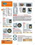
PRODUCT OVERVIEW............................................................................................................................. 1
2 . G E T T I N G S T A R T E D ............................................................................... 3
2.1
2.2
2.3
OVERVIEW ............................................................................................................................................... 3
SYSTEM REQUIREMENTS ...................................................................................................................... 3
INSTALLING CALTOOL FOR RPM3........................................................................................................ 3
2.3.1
2.3.2
2.3.3
2.3.4
2.3.5
WINDOWS 3.1X USERS................................................................................................................................ 3
WINDOWS 95 ................................................................................................................................................ 4
INSTALLATION FILES .................................................................................................................................. 4
RUNNING THE PROGRAM ........................................................................................................................... 5
OPERATING PRINCIPLES............................................................................................................................ 5
3 . M A I N P R O G R A M F O R M ......................................................................... 7
3.1
3.2
OVERVIEW ............................................................................................................................................... 7
CURRENT SETUP FOLDER..................................................................................................................... 7
3.2.1
3.2.2
3.2.3
3.3
RPM3 INFORMATION ................................................................................................................................... 8
REFERENCE INFORMATION ....................................................................................................................... 8
TEST INFORMATION .................................................................................................................................... 8
TEST DISPLAY TAB................................................................................................................................. 9
3.3.1
3.3.2
3.3.3
DATA GRID ................................................................................................................................................... 9
DATA GRAPH................................................................................................................................................ 9
PANEL DISPLAY......................................................................................................................................... 10
4 . M A I N F O R M M E N U O P T I O N S ............................................................... 11
4.1
RUN MENU ............................................................................................................................................. 11
4.1.1
4.1.2
4.1.3
4.1.4
4.2
SETUP MENU ......................................................................................................................................... 21
4.2.1
4.2.2
4.2.3
4.3
RUN TEST ................................................................................................................................................... 11
4.1.1.1 TEST SETUP ............................................................................................................................... 12
4.1.1.2 DATA ACQUISITION.................................................................................................................... 14
4.1.1.3 DATA VERIFICATION.................................................................................................................. 16
4.1.1.4 SAVING TEST DATA ................................................................................................................... 17
4.1.1.5 DATA MANIPULATION ................................................................................................................ 17
MANUAL ENTRY TEST............................................................................................................................... 18
4.1.2.1 MANUAL TEST SETUP ............................................................................................................... 18
4.1.2.2 MANUAL TEST, DATA ENTRY.................................................................................................... 19
REMOTE COMMUNICATIONS.................................................................................................................... 20
EXIT ............................................................................................................................................................. 20
COMMUNICATIONS .................................................................................................................................... 21
4.2.1.1 RS-232 ......................................................................................................................................... 21
4.2.1.2 IEEE-488...................................................................................................................................... 22
READ RPM3 ................................................................................................................................................ 22
SETUP REFERENCE .................................................................................................................................. 22
TEST FILE MENU ................................................................................................................................... 23
Page i
©2000 DH Instruments, Inc.
CalTool™ for RPM3™ User’s Manual
4.3.1
4.3.2
4.3.3
4.4
DATA MANIPULATION MENU ............................................................................................................... 26
4.4.1
4.4.2
4.4.3
4.5
SELECT TEST FILE .................................................................................................................................... 23
EDIT/CREATE TEST ................................................................................................................................... 23
4.3.2.1 AUTO FILL SETUP ...................................................................................................................... 23
4.3.2.2 DEFINING TEST POINTS............................................................................................................ 24
4.3.2.3 TEST CRITERIA .......................................................................................................................... 24
4.3.2.4 DEFAULT.TST FILE..................................................................................................................... 25
DELETE TEST FILE .................................................................................................................................... 25
VIEW CALIBRATION COEFFICIENTS........................................................................................................ 26
4.4.1.1 PRINT .......................................................................................................................................... 26
4.4.1.2 RE-LOAD RPM3 .......................................................................................................................... 27
4.4.1.3 EXIT ............................................................................................................................................. 27
OPEN CURRENT DATA FILE ..................................................................................................................... 27
OPEN SAVED DATA FILE .......................................................................................................................... 27
ABORT .................................................................................................................................................... 27
5 . D A T A M A N I P U L A T O R .......................................................................... 29
5.1
5.2
OVERVIEW ............................................................................................................................................. 29
DISPLAY INFORMATION ....................................................................................................................... 29
5.2.1
5.2.2
5.2.3
5.2.4
5.3
TEST INFORMATION .................................................................................................................................. 29
REFERENCE INFORMATION ..................................................................................................................... 30
DATA GRAPH.............................................................................................................................................. 30
RPM3 INFORMATION ................................................................................................................................. 30
MENU OPTIONS ..................................................................................................................................... 30
5.3.1
5.3.2
5.3.3
FILE MENU .................................................................................................................................................. 30
5.3.1.1 OPEN DATA FILE ........................................................................................................................ 30
5.3.1.2 VIEW CURRENT REPORT .......................................................................................................... 30
5.3.1.3 VIEW SAVED REPORT ............................................................................................................... 31
5.3.1.4 SAVE REPORT............................................................................................................................ 31
5.3.1.5 PRINT CURRENT REPORT ........................................................................................................ 31
5.3.1.6 PRINT SAVED REPORT.............................................................................................................. 32
5.3.1.7 EXIT ............................................................................................................................................. 32
CALIBRATION MENU ................................................................................................................................. 32
5.3.2.1 ACTIVATE CALIBRATION ...........................................................................................................32
5.3.2.2 COPY CALIBRATION TO ............................................................................................................32
5.3.2.3 RESTORE.................................................................................................................................... 33
5.3.2.4 VIEW CALIBRATION COEFFICIENTS ........................................................................................ 33
OPTIONS ..................................................................................................................................................... 33
5.3.3.1 INCLUDE GRAPH IN REPORT.................................................................................................... 33
6 . C A L C U L A T I O N S .................................................................................. 35
6.1
6.2
OVERVIEW ............................................................................................................................................. 35
DETERMINING FACTORY PRESSURE................................................................................................. 36
6.2.1
6.2.2
6.3
DETERMINING PA/PM ........................................................................................................................... 37
6.3.1
6.3.2
6.4
6.5
ABSOLUTE RPTS IN ABSOLUTE MEASUREMENT MODE AND GAUGE RPTS ..................................... 36
ABSOLUTE RPT IN GAUGE MEASUREMENT MODE ............................................................................... 36
ABSOLUTE RPT IN ABSOLUTE MEASUREMENT MODE ........................................................................ 37
ABSOLUTE RPT IN GAUGE MEASUREMENT MODE AND GAUGE RPTS .............................................. 37
ZNATERR, ZOFFSET MODIFICATIONS................................................................................................ 38
DETERMINING AS LEFT DATA............................................................................................................. 38
©2000 DH Instruments, Inc.
Page ii
CalTool™ for RPM3™ User’s Manual
>+,6/=
Table 1.
Installation Files..........................................................................................................................4
031?</=
Figure 1.
Figure 2.
Figure 3.
Figure 4.
Figure 5.
Figure 6.
Figure 7.
Figure 8.
Figure 9.
Figure 10.
Figure 11.
Figure 12.
Figure 13.
Figure 14.
Figure 15.
Figure 16.
Figure 17.
Main Form: Current Setup Folder .............................................................................................7
Main Form: Test Display Tab ....................................................................................................9
Choose Pressure Units Screen................................................................................................12
Enter RPM3 Information Screen ..............................................................................................13
Select Range to Calibrate Screen............................................................................................13
Pop-up Panel Screen ...............................................................................................................14
Enter Reference Pressure Screen ...........................................................................................15
Enter Test Data (kPa) Screen ..................................................................................................17
Enter the Calibration Coefficients Screen ................................................................................19
Remote Communications Screen ............................................................................................20
Serial Communications Setup Screen......................................................................................21
Setup IEEE Interface Screen ...................................................................................................22
Pressure Reference Information ..............................................................................................22
Test File Editor .........................................................................................................................25
Calibration Information of RPM3 SN: 107 ...............................................................................26
Data Manipulator Screen .........................................................................................................29
Data Manipulator: Calibration Report Screen .........................................................................31
Page iii
©2000 DH Instruments, Inc.
CalTool™ for RPM3™ User’s Manual
+,9?>>23=7+8?+6
Manual Conventions
-+?>398S]_]ONSXWKX_KV^YSNOX^SPc_]O\aK\XSXQ]KXNMK_^SYX]
89>/ S] _]ON SX ^RO WKX_KV ^Y SNOX^SPc YZO\K^SXQ KXN KZZVSMK^SYX] KN`SMO KXN
KNNS^SYXKVObZVKXK^SYX]
[ ] indicates direct function keys (e.g., [RANGE]).
< > indicates screen displays (e.g., <1yes>).
©2000 DH Instruments, Inc
Page iv
.
CalTool™ for RPM3™ User’s Manual
38><9.?->398
352'8&729(59,(:
CalTool for RPM3 is intended to provide assistance in the calibration of RPM3 reference
pressure monitor. CalTool steps the operator through the calibration process, gathers data, calculates
optimum calibration adjustment coefficients, writes new coefficients to RPM3 and generates
calibration reports.
,OPY\O _]SXQ -KV>YYV \OKN KXN ^RY\Y_QRVc PKWSVSK\SdO cY_\]OVP aS^R ^RO <:7 9ZO\K^SYX KXN
7KSX^OXKXMO7KX_KV-+63,<+>39890</0/</8-/><+8=.?-/<=
Page 1
©2000 DH Instruments, Inc.
CalTool™ for RPM3™ User’s Manual
89>/=
©2000 DH Instruments, Inc.
Page 2
CalTool™ for RPM3™ User’s Manual
1/>>381=>+<>/.
29(59,(:
This section explains how to install CalTool for RPM3 on your computer and provides an overview
of the startup procedures.
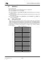
6<67(05(48,5(0(176
CalTool for RPM3 requires the following minimum PC configuration. If your PC does NOT meet these
minimum requirements, the software will NOT run as designed.
•
Windows 3.1x or Windows 95
•
20 MHz 100 % IBM compatible 386 processor
•
4 Mbytes of RAM
•
4 Mbytes of free hard disk space
,167$//,1*&$/722/)25530
:,1'2:6;86(56
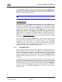
å Start Microsoft Windows.
Insert the CalTool for RPM3 Installation disk #1 in your floppy drive.
ê From Program Manager, select the File menu and choose <Run>.
In the Run dialog box, type a:\setup or b:\setup, depending on which drive you placed the
installation disk in.
The setup program will step through the installation process prompting you for entry of the
desired information.
ñ To run CalTool for RPM3, double click the RPM3 CalTool icon in the DHI program group.
Page 3
©2000 DH Instruments, Inc.
CalTool™ for RPM3™ User’s Manual
:,1'2:6
å Start Windows 95.
Insert the CalTool for RPM3 Installation disk #1 in your floppy drive.
ê Press the [Start] button then select <Run>.
In the Run dialog box, type a:\setup or b:\setup, depending which drive you placed the
installation disk in.
The setup program will step through the installation process prompting you for entry of the
desired information.
ñ To run CalTool for RPM3, press the [Start] Button, select <Programs>, select <DHI> and
click on the CalTool icon.
,167$//$7,21),/(6
Some users require knowledge of all files that are copied to their PC to avoid conflicts
between different versions of the same file. For this reason, a list of installation files is in
Table 1. The majority of users will have little use for this information. The program executable
and default configuration and test files are always copied to the directory selected in the
Setup process. All Windows based library files are copied to your computer’s Windows
system directory.
Table 1. Installation Files
FILE
CT_RPM3.exe
CT_RPM3.cfg
Default.Tst
GRID.VBX
CMDIALOG.VBX
GRAPH.VBX
MSCOMM.VBX
THREED.VBX
TX4VBB.VBX
TABPRO11.VBX
IMPPRO11.VBX
VTSS.VBX
FM.DLL
TX_BMP.FLT
TX_RTF.DLL
TX_TIFF.FLT
TX_WMF.FLT
TXTOOLS.DLL
TXB.DLL
VBRUN300.DLL
VTSSDLL.DLL
GSWDLL.DLL
GSW.EXE
WNDTOOLS.DLL
IC.INI
IC.DLL
©2000 DH Instruments, Inc
DATE
Changes with version
Changes with version
Changes with version
1994/3/25
1993/4/28
1993/4/28
1993/4/28
1996/8/24
1995/3/15
1995/9/8
1994/9/16
1995/2/8
1995/3/15
1995/3/15
1995/3/15
1995/3/15
1995/3/15
1995/3/15
1995/3/15
1993/5/12
1995/2/8
1993/4/28
1993/4/28
1995/3/15
1995/3/15
1995/3/15
Page 4
.
CalTool™ for RPM3™ User’s Manual
5811,1*7+(352*5$0
Before running CalTool, establish a remote connection with the host PC by connecting your
PC to the RPM3 using a standard RS-232 cable and connecting one of the PC’s
communications ports to the RPM3’s Com1.
CEC and National Instruments IEEE-488 cards are also supported by CalTool for remote
operation using the RPM3’s IEEE-488 interface. IEEE-488 users should connect a GPIB
cable to the IEEE-488 port on the RPM3 and to the desired IEEE card in the host PC.
See the RPM3 Operation and Maintenance Manual (Remote) for additional information on
RPM3 communication interfaces and settings.
Once you have set up the interface between the RPM3 and your PC you are ready to run
the program. Double click the CalTool Icon in the RPM3 CalTool program group or select the
CalTool Icon from the Windows 95 Start - Programs menu.
When CalTool for RPM3 first loads, it attempts to use the communication settings that were in
use when the program was last run or the default communications settings (from the
CT_RPM3.cfg configuration file).
If communications are correctly established, all
communications-based menu options are enabled and the RPM3 information is loaded
and displayed. Otherwise, the menu options will remain disabled until communications are
properly established.
23(5$7,1*35,1&,3/(6
CalTool for RPM3 is an application designed to provide assistance in the calibration of RPM3
reference pressure monitors. It contains all of the necessary tools to simplify and enhance the
efficient performance of valid calibrations on the unit.
All tests are separated into two phases.
•
Data acquisition
•
Data manipulation
The data acquisition phase is the process of obtaining test data that is later manipulated to
obtain new calibration coefficients. Data can be obtained by either running a test through the
Run Test menu option, which steps through points in a test file or by entering each test point
manually using the Manual Entry Test option. All test information is written to a comma
delimited data file that can be imported into other applications for further analysis.
In the data manipulation phase of a test, you can view the calculated calibration coefficients
(PA/PM) for the RPM3 test range and the predicted as left data. The new calibration
coefficients can be activated to any range equal to or less than the range tested on the
same RPT. After the calibration is activated, a report including a graph can be created to
document the calibration.
Page 5
©2000 DH Instruments, Inc.
CalTool™ for RPM3™ User’s Manual
89>/=
©2000 DH Instruments, Inc.
Page 6
CalTool™ for RPM3™ User’s Manual
7+38:<91<+709<7
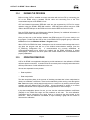
29(59,(:
The main program form contains all of the necessary display information and menu options to set up
and calibrate all ranges of the RPM3. There are two folders on this form.
•
One folder containing the current setup information
•
One folder containing the current test data display
The following sections contain information on the contents and purpose of the two folders followed by
itemized information on the menu options. Following the description of each menu option, are forms
and other visual information associated with that option.
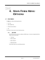
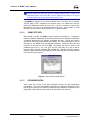
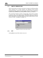
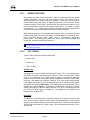
&855(176(783)2/'(5 The current setup folder displays the currently selected RPM3, pressure reference and test
file information.
Figure 1. Main Form: Current Setup Folder
Page 7
©2000 DH Instruments, Inc.
CalTool™ for RPM3™ User’s Manual
530,1)250$7,21
The top left quadrant of the current setup folder contains all of the relevant RPM3 information
for running a test. Once communication is established with the RPM3, this data is read and
displayed automatically. This data is only updated when communications are first established
(e.g., a double click is made anywhere on the display), or when <Read RPM3> is selected
from the Setup menu. Each of the fields are read-only so NO edits or selections can be made
by choosing any particular field (see Section 4.2.2).
5()(5(1&(,1)250$7,21
The top right quadrant of the current setup folder contains information on the device that will
be used to supply reference pressure to the RPM3 in the calibration process.
At startup, the last <Pressure Reference Model> and <Identification Used> displays in the
corresponding field. Double clicking any area within the pressure reference frame is a
shortcut to choosing the <Setup Reference> menu option which gives you the ability to edit
reference information (see Section 4.2.3).
7(67,1)250$7,21
The bottom right quadrant of the current setup folder contains test information.
Test Information refers to the definition of the calibration test routine that will be run.
The test points from the currently selected test file display in this section. At startup, the last
test used prior to the closing of the program should display in these fields. If an error occurs in
the process of loading the previous test file, NO test information displays. Any time a new test
is selected or edited it displays in this area the number and value of all test data points in the
list box. Test points can be viewed by scrolling down in the list box. Test units can either be
in % FS of the current DUT range or in RPM3 supported pressure units. The stability criterion
is also based on a % FS value of each range. Dwell time is the only range independent value
that can be entered in a test file. Double click any test information field as a shortcut to the
<Select Test> menu option or right click any field as a shortcut to all <Test File>
menu options.
©2000 DH Instruments, Inc.
Page 8
CalTool™ for RPM3™ User’s Manual
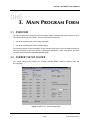
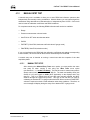
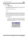
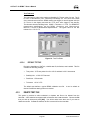
7 ( 6 7 ' , 6 3 / $ < 7 $ % While running a test, the test display tab should be the main focus of attention. All relevant test
information displays for the range under calibration. The current range, test progress, operator and
starting date and time also display.
Figure 2. Main Form: Test Display Tab
'$7$*5,'
The data grid displays the RPM3 and reference pressures and the % FS error for each
test point. This is the only data that displays during the data acquisition phase of the test.
Only the current test data displays at any given time during a test. To view old data, one of
the data manipulation options should be used to view the corresponding data file
(see Section 5). After the test is complete, the data will remain on the form for view
purposes only. The data is NOT erased until the next test is setup.
'$7$*5$3+
The graph provides a real time plot of all data up to the current point of the range being tested.
The % FS error (difference between RPM3 pressure and reference pressure) is plotted.
NO data is plotted until at least two test points are taken. For this reason, the graph is blank
at the beginning of a test.
Page 9
©2000 DH Instruments, Inc.
CalTool™ for RPM3™ User’s Manual
3$1(/',63/$<
Above the graph is a real time display of RPM3 pressure, atmospheric pressure, ready status,
and the current rate of change of pressure. This information only displays after a test
is started. The ready status will turn GREEN when the pressure meets the stability criteria as
specified in the test file. Otherwise, the ready status is RED.
©2000 DH Instruments, Inc.
Page 10
CalTool™ for RPM3™ User’s Manual
7+3809<77/8?
9:>398=
5810(18
The RUN menu offers the following selections:
•
Run Test
•
Manual Data Entry
•
Remote Communications
•
Exit
The function of each choice is in the following sections.
5817(67
RUN TEST should be selected to calibrate an RPM3 range. All tests, including Manual Entry
Tests, have four main areas:
•
Test Setup
•
Data Acquisition
•
Data Verification
•
Data Manipulation
Each of these steps are in the following sections.
Page 11
©2000 DH Instruments, Inc.
CalTool™ for RPM3™ User’s Manual
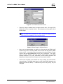
7(676(783
TEST SETUP is valid for both run test and manual entry test options
(see Section 4.1.2). The process is the same. You may use current valid settings or
the software can allow the reference and test to be selected as part of the
setup procedure. It all depends on your responses to the setup prompts. Following is
a list of steps that are followed as part of the test setup.
+Xc^SWOcY_Z\O]]E/=-GY\MRYY]OE-+8-/6GPY\KXYZ^SYX^RO]O^_ZZ\YMON_\OS]
KLY\^ONK]aOVVK]^RO^O]^
• Verify pressure reference
• Verify test file
• Determine test units
When the selected test file contains test points in % FS, you must select the pressure
units to use for the test. Select the units and the corresponding measurement
mode from the Test Units form and press [OK]. Press the [↓] to scroll through the
units list. The RPM3 will change to the selected units so make sure that your
Reference device is in the same units.
Figure 3. Choose Pressure Units Screen
•
©2000 DH Instruments, Inc.
Manual entry tests require the user to enter the desired test tolerance. The RPM3
information is also required if there is NOT a remote RPM3 or the test data does
NOT correspond to the current remote unit. The RPM3 setup form is used to
facilitate the input of the RPM3 information. Information pertaining to the model
and software version fields can be obtained by pressing and holding the [ESC]
key on the RPM3 front panel. The model, which represents the internal RPTs of
the RPM3, displays first followed by the RPM3 software version on the bottom
half of the display. Select the desired test range and corresponding full scale
value and measurement mode.
Page 12
CalTool™ for RPM3™ User’s Manual
Figure 4. Enter RPM3 Information Screen
•
Select the range to calibrate from the range selection form. All ranges of the
RPM3 will list in the drop down list box. Press the [↓] to scroll through the list of
RPM3 ranges.
9XVc YXO \KXQO MKX LO MKVSL\K^ON K^ K ^SWO =OVOM^ ^RO \KXQO cY_ aS]R ^Y
MKVSL\K^OKXNZ\O]]E/8>/<GY\]OVOM^^ROE95GL_^^YX
Figure 5. Select Range to Calibrate Screen
•
Next, you are asked whether you wish to run the test with the RPM3 AutoZ
function ON or OFF. Selecting <Yes> will turn AutoZ ON and selecting <No>
will turn it OFF. Your selection should correspond to how the RPM3 is normally
used so that the as received data from the test is meaningful. The current
state of AutoZ displays with this prompt when there is an RPM3
remotely connected. For more information, see the RPM3 Operation and
Maintenance Manual, AutoZ and Principle, As Received/As Left Data.
•
CalTool sets the RPM3 to the desired test range, stability test, measurement
units and mode. The RPM3 Head value is set to 0 (see RPM3 Operation and
Maintenance Manual, HEAD). If a Manual Entry test is being set up, this part
is skipped.
Page 13
©2000 DH Instruments, Inc.
CalTool™ for RPM3™ User’s Manual
•
Enter your name when prompted to enter the operator name.
•
Finally you are prompted to <Run the Test>. Press [OK] when ready.
Make sure that the supply pressure is below the upper limit of the test range
then press [OK]. This will deactivate SDS for the RPT that is being calibrated
(see RPM3 Operation and Maintenance Manual, SDS Self Defense Systems).
Invalid Test Setup
During the setup process certain combinations of test ranges, test files and
measurement units and mode are invalid. When this occurs, an error message
displays and the test setup is aborted. The following conditions lead to an invalid
test setup:
•
Gauge RPM3 RPT (Reference Pressure Transducer) and
measurement mode. Gauge RPTs can only be run in gauge mode.
•
A manual entry test is being set up with an absolute RPT in gauge measurement
mode and AutoZ is turned ON. A calibration in this mode requires knowledge of
real time pressure offset values to achieve a valid calibration. For this reason,
manually entering the RPM3 and Reference pressures would lead to an
invalid calibration.
•
Pressure values in the test file exceed the selected RPT range.
absolute
'$7$$&48,6,7,21
Data acquisition is the process of acquiring test data from both the RPM3 and
pressure reference. During this phase of the test, the RPM3 pressure is updated
continuously in the pressure display area above the graph.
For each point there is a process of:
å Setting the pressure as specified by the test file and dwelling for the test
dwell time
Entering the reference pressure
ê Logging the RPM3 pressure
At each step, you are prompted by a pop-up panel that appears in the upper left-hand
corner of the test display folder.
Figure 6. Pop-up Panel Screen
©2000 DH Instruments, Inc.
Page 14
CalTool™ for RPM3™ User’s Manual
The [Back] button on the panel should be used to repeat steps that
occurred incorrectly. For instance, you entered the wrong reference pressure.
On the first point of a test, the [Back] button is disabled. Beyond the first point,
choosing [Back] will take you to the previous step up to the setting of the previous
test pressure On the last test point, a message box displays asking to repeat the
last step. Selecting <Yes> is identical to pressing the [Back] button.
Setting Test Pressure
As mentioned above, you will be prompted by a pop-up panel to set each pressure of
the test. If the test file has % FS test points, they are converted to the test pressure
units in the correct percentage of the RPM3 pressure range before being displayed on
the panel. While the panel displays, you should set the test pressure to the displayed
pressure within reasonable limits (see RPM3 Operation and Maintenance Manual,
Equipment Required).
Once the reference pressure has been set, press [OK] to start the dwell count down.
Press [Back] to go the previous step in the data acquisition phase of the test. In this
case, pressing [Back] will take you to Step 3. Take RPM3 reading.
Whenever the [OK] button is pressed, the panel hides and the dwell count
down begins. Every second is updated on the status bar until <0> displays.
Meanwhile, the RPM3 pressure is still constantly updated in the test display.
During the dwell, NO pressure adjustments should be made. This time should be
used to allow the pressure and system to stabilize (two to three minutes dwell time
is recommended). At the end of the dwell, a check of the stability is made. If the
pressure is unstable, a warning message displays. This is just a warning to avoid
taking data when the pressure stability is outside of the stability limit.
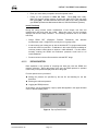
Enter Reference Pressure
After the dwell countdown and stability check are complete, the pop-up panel will
prompt you to enter the reference pressure. The expected reference pressure value
is the nominal test point value of the test file in the current test units. This number will
display in the entry field. Enter the actual reference pressure and press [OK].
Press [Back] if you want to reset the RPM3 pressure.
Figure 7. Enter Reference Pressure Screen
Page 15
©2000 DH Instruments, Inc.
CalTool™ for RPM3™ User’s Manual
If it is impractical to enter the actual reference pressure values the nominal values
which prompt automatically at each test point can be entered. The actual reference
pressures can be entered after running the test during the data verification phase.
However, this field cannot be left blank.
3PXYWSXKV\OPO\OXMOZ\O]]_\O`KV_O]K\OOX^O\ONaRSVO\_XXSXQ^RO^O]^^ROQ\KZRKXN
0=O\\Y\^YNS]ZVKcaSVVPYVVYaKVYXQaS^R^RO^O]^L_^aSVV89>LOKMM_\K^O
Take RPM3 Pressure
Following the entry of the reference pressure the pop-up panel again displays but this
time it prompts you to press [OK] to log the RPM3 pressure. The reference pressure
displays in a non-editable field so you can confirm that it was entered correctly.
To change the reference pressure pressing [Back] will go to the previous step and
allow the edit of the reference pressure. Clicking [OK] will log the current RPM3
pressure and update the main data grid and graph with this value and the
corresponding % FS error. <T> appears with the % FS error display to flag out of
tolerance values. An s appears if the RPM3 pressure was unstable (outside of the
stability limit) at the time of the reading. Return to Setting Test Pressure
Section 4.1.1.2, Setting Test Pressure. The three step process repeats until all test
points are completed.
Any time the next test file point is exactly the same as the current test point, the data
of the point taken is automatically copied to the next point. This is to assure proper
weighting of the end point in a typical ascending and descending
calibration sequence. This does NOT mean that a test full of identical points will just
log data for the first point. The software only checks the first point from current test
point to copy data to. So identical data is logged in pairs.
'$7$9(5,),&$7,21
After the final test point is taken the data verification form displays allowing the
reference pressure values to be edited. The RPM3 model, serial number, test units
and test range display at the top of the form followed by all of the data taken during
the test. This final edit is available for users who can NOT enter actual reference
pressures during the test and must enter them now. The [Clear Display] button is
disabled because this erases all test data. This button is only used for manual
entry tests.
Only existing reference pressure values can be edited. NO new test points can be
added and NO existing test points can be deleted. Edit reference pressure values by
selecting the desired row and editing the displayed value. Make sure to enter the
reference pressure value in the current test units. After the edit, press [ENTER] and
the % FS error is recalculated based on the entered reference pressure. If undesired
edits were made, click the [Restore Data] button to refresh the display with the
original test data.
©2000 DH Instruments, Inc.
Page 16
CalTool™ for RPM3™ User’s Manual
<O]^Y\O _ZNK^O] KVV NK^K 89> T_]^ ^RO M_\\OX^Vc ]OVOM^ON PSOVN 3P ^RO\O S] KX
_XObZOM^ON Z\YLVOW SX ^RO ^O]^ NK^K MVSMU ^RO E<OZOK^ >O]^G L_^^YX ^Y \O\_X ^RO
OX^S\O^O]^aS^RY_^QYSXQ^R\Y_QR^RO>O]^=O^_ZZ\YMO]]
If [CANCEL] is pressed on the data verification form, the entire test is aborted.
The test data is NOT completely lost because there is a default test data file
(named CT_RPM3.dat) created for every test. This file is created to preserve test
information in the event of an accidental abort or an error. Any text editor or word
processor can be used to view the contents of CT_RPM3 if desired.
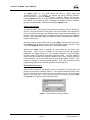
6$9,1*7(67'$7$
After all data is verified, click [OK] to save the data to a test data file. The data file
makes it possible to manipulate the test data to determine new calibration coefficients.
A standard Windows file box appears to facilitate this step. CalTool will create a
directory named by the serial number of the RPM3. It is a good procedure to save all
data files for any RPM3 in the corresponding directory. Determine the name and
extension of the data file and click [OK]. By default, the data file name is the
calibrated range (H1, L1, etc.), the year, and the Julian Day (0 to 365 or 366 for
leap year) with a .dat file extension (RR_YYDDD.dat). After the data file is properly
saved, the Data Manipulator form displays with all of the calibration information stored
in the data file (see Section 5).
Figure 8. Enter Test Data (kPa) Screen
'$7$0$1,38/$7,21
After a data file is saved in the data verification process, the data manipulation
form displays. This form automatically calculates new calibration coefficients for the
test range and gives you the option to activate the new calibration coefficients to any
ranges that are less than the test range on the same RPT (see Section 5).
Page 17
©2000 DH Instruments, Inc.
CalTool™ for RPM3™ User’s Manual
0$18$/(175<7(67
A manual entry test is available to allow you to enter RPM3 and reference pressure data
independently from actually running a calibration. With this feature, you can input and perform
calculations using data that were collected earlier or independently from CalTool. CalTool will
need to know the calibration coefficients and RPM3 conditions.
For complete manual entry, the following RPM3 information will need to be available:
•
Range
•
Pressure measurement units and mode
•
AutoZ ON or OFF when test data was taken
•
PA/PM
•
ZOFFSET (if AutoZ ON, both start and finish values if gauge mode)
•
ZNATERR (if AutoZ ON, absolute mode)
If you are interfaced to the RPM3 with the calibration coefficients and settings corresponding
to the test data, CalTool will read all these values automatically from the RPM3.
A manual entry test is identical to running a normal test with the exception of the data
acquisition phase.
0$18$/7(676(783
After choosing the <Manual Entry Test> menu option, you must perform the same
test setup as when running a test using the <Run Test> menu option
(see Section 4.1.1.1, Invalid Test Setup). The test file name for manual entry tests is
always manual entry data since there is NO file. The dwell and stability times (see
Section 4.3.2.3) are logged as <N/A> (NOT Applicable) on the displays and in the
data file. This is to indicate that the test data was manually entered and NOT
obtained through the regular test process. This type of test can NOT be used for
calibrating an absolute RPT in gauge mode with AutoZ ON as real time ATMOFFSET
values are required to obtain a valid calibration under these conditions. Therefore, an
error message will display during the setup of an absolute RPT in gauge mode.
©2000 DH Instruments, Inc.
Page 18
CalTool™ for RPM3™ User’s Manual
0$18$/7(67'$7$(175<
After the test setup is complete, the Data Verification form immediately displays with
NO data. Enter the reference and RPM3 pressure readings in the current
measurement units (displayed at the top of the form). The % FS error value is
automatically calculated after data has been entered into the other columns in the
same row. Place data in consecutive rows because the first blank row marks the end
of the data when the data file is being created. This nulls all data entered after the
blank row. The <Repeat Test> and <Restore Data> options that display at the end
of a test run using the Run Test option are NOT available. However, the
[Clear Display] button is available allowing you to clear all data entered, NOT just the
currently selected field. Use the [BACKSPACE] key to clear an individual cell.
0Y\ `KVSN MKVSL\K^SYX MYOPPSMSOX^] ^Y LO MKVM_VK^ON MKVSL\K^SYX NK^K ZYSX^] SX QK_QO
WOK]_\OWOX^WYNOW_]^]^K\^KXNOXNaS^RdO\Y
Clicking [OK] has the same effect as described in Section 4.1.1.4. It triggers the
saving of a data file and displays the Data Manipulator form (see Section 5).
Clicking [CANCEL] aborts the test in the same manner as in a automated test,
however there is NO default data file to fall back on. All test information is lost after
[CANCEL] is pressed.
After [OK] is pressed and before the data file can be created, the calibration
coefficients must be entered. For Absolute RPT gauge mode calibrations and gauge
RPT calibrations with AutoZ ON, you must also enter separate Starting and Ending
ZOFFSET values in Pascal (Pa) units. This is because ZOFFSET can change over
the course of a test. For all other test configurations, the Ending value of ZOFFSET
displays as <N/A> and only the Starting ZOFFSET value is required.
Figure 9. Enter the Calibration Coefficients Screen
Page 19
©2000 DH Instruments, Inc.
CalTool™ for RPM3™ User’s Manual
5(027(&20081,&$7,216
Remote communications can be used to send discrete commands to the RPM3 using RPM3
remote commands (see the RPM3 Operations and Maintenance Manual, Remote
Operation Descriptions). Any data that is typed into the Command window is transmitted to
the RPM3 after the [Send] button is clicked or [Enter] is pressed. The commands can be
entered manually or selected from the drop down list box of commands previously sent.
After a command is transmitted, a maximum 10 second delay is used to wait for a response.
If a response is NOT received within this interval, <Device Error> displays in the Reply field.
Otherwise, the response of the RPM3 will display. In the event of a Device Error, make sure
that the RPM3 and PC are connected and that the interface settings match the current
settings of the RPM3. Click [Exit] or press [Esc] to exit.
Figure 10. Remote Communications Screen
(;,7
Selecting [Exit] causes the RPM3 calibration utility to exit.
©2000 DH Instruments, Inc.
Page 20
CalTool™ for RPM3™ User’s Manual
6(7830(18
&20081,&$7,216
If communications are NOT automatically established when the program first loads,
all communications-based menu options are disabled. Use this option to determine the
correct interface and enable all menu options.
The Communications menu contains two sub-menus:
•
RS-232
•
IEEE
Choose the option that corresponds to the type of remote interface that you intend to use to
communicate with the RPM3 from a host PC. When valid communications are established,
the RPM3 data is loaded into memory and displayed on the current setup folder of the
main form. Then all communications-based menu options are enabled. Before choosing
either option, make sure the PC and RPM3 are properly connected and that the RPM3 power
is ON. For additional information on interfacing RPM3, see the RPM3 Operation and
Maintenance Manual, Remote.
56
To use RS-232 communications, choose the PC’s Com Port, Baud Rate, Parity, Data
Bits and Stop bits from the RS-232 Setup Form that correspond to the setting of the
RPM3 Com1 port. To change a setting, press the corresponding [↓] and click the
desired value. After all selections are complete, click [OK]. Pressing [CANCEL]
aborts the operation and closes the form.
Figure 11. Serial Communications Setup Screen
Page 21
©2000 DH Instruments, Inc.
CalTool™ for RPM3™ User’s Manual
,(((
Only CEC and National Instruments IEEE-488 controller cards are supported
by CalTool. Choose the desired controller card and make sure the card and DUT
address fields are set to the correct value and click [OK]. If a communication link is
established, all settings are updated as previously described. Pressing [Cancel]
aborts the form.
Figure 12. Setup IEEE Interface Screen
5($'530
The <Read RPM3> menu option should be used to re-load all RPM3 information into memory
and display it on the main form. This option should be used if changes are made to any
calibration coefficient value after the program has already loaded the RPM3 data, or if a new
RPM3 has been connected. Other than the menu option, users may double click any of the
RPM3 display fields on the Current Setup folder of the main form to perform the same task.
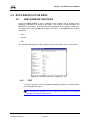
6(7835()(5(1&(
The Reference Setup form is provided to define the instrument that will be used to supply
reference pressure values in the calibration. This information will be saved in the test data file.
Selecting the <Setup Reference> menu choice displays the Reference Setup Form. Fill in
the Model and Identification fields for the applicable reference and press [OK]. In most cases,
the Identification field should contain the serial number of the pressure reference used as well
as any other M&TE information for that particular standard.
,Y^R PSOVN] RK`O MRK\KM^O\ VSWS^] +P^O\ MRK\KM^O\] K\O OX^O\ON KVV XYXNOVO^O Y\
LKMU]ZKMO MRK\KM^O\] K\O USVVON.Y_LVOMVSMUSXQKXcYP^RO<OPO\OXMO=O^_ZSXPY\WK^SYXYX
^RO-_\\OX^=O^_ZNS]ZVKcPYVNO\YP^ROWKSXPY\WS]K]RY\^M_^^Y^RS]WOX_YZ^SYX
Figure 13. Pressure Reference Information
©2000 DH Instruments, Inc.
Page 22
CalTool™ for RPM3™ User’s Manual
7(67),/(0(18
The Test File menu is provided to allow selecting, creating and editing of the test files that define the
calibration sequence and conditions.
Clicking any test display field with the right mouse button is a short cut to this menu. The options in
this menu allow the user to select, edit, create, and destroy test files.
6(/(&77(67),/(
Use this selection to choose a test file. Once selected, a standard file box displays listing the
test files available in the test directory. Choose the desired test file and click [OK]. If the test
file is valid, it is loaded into memory and displayed on the main form’s Current Setup folder in
the test information area. Double click any Test Information field as a short cut to selecting a
test file.
(',7&5($7(7(67
This action displays the test file editor loaded with any current test information. The test editor
is used to create a file that defines a test sequence and corresponding criteria to be used
during a test. The test editor is divided into three sections:
•
Auto Fill Setup
•
Test Point Data
•
Test Criteria
After all of the necessary test settings are determined, press the [Save] button to save the
test file. Determine the path and file name of the test file in the file box that displays then
press [OK]. It is good practice to save all test files to the test directory. However, it is
NOT required. The default extension to all test files is .tst. The test editor will close and all of
the test settings will display in the test information fields of the main form.
$872),//6(783
The auto fill setup is a shortcut tool for quickly defining a set of test points that are
evenly incremented. Starting pressure defines the starting test point and ending
pressure defines the last test point. The step value determines the step increment
between the starting and ending pressures. Test points will be defined incrementing
by the step value from the starting pressure to the ending pressure and back to the
starting pressure. The ending pressure is always repeated. If the values are such
that the range from starting to ending pressures is NOT an even multiple of the
step value, the last step value will be adjusted to end exactly on the ending pressure.
Test point values defined by the auto fill setup are copied into the test point fields
when auto fill is pressed. All test points can be cleared by choosing the
[Clear] button. The user is allowed to modify points created by an auto fill.
+_^YPSVVO\K]O]KVVM_\\OX^^O]^ZYSX^]LOPY\OPSVVSXQ
Page 23
©2000 DH Instruments, Inc.
CalTool™ for RPM3™ User’s Manual
'(),1,1*7(6732,176
Only positive test point values are allowed. Make sure that test points are always
entered sequentially. Do NOT skip fields between points. Test points must be
specified in either % Full Scale (% FS) or in pressure. % FS points are in % FS of the
current RPM3 range being tested. A single properly setup % FS test can be used to
calibrate all ranges of any RPM3. Pressure units and measurement mode for % FS
tests are determined during the test setup process after a test option is chosen
(see Section 4.1.1.1). When pressure points are entered, the pressure measurement
units and mode must be determined from the list box below the option.
When defining test points, it is preferable that the points step in consistent increments
throughout the span of the current test range in first ascending then descending order.
Every ascending pressure point should have a corresponding descending
pressure point. This will properly balance the data for the linear regression that
occurs after all data is acquired (see Section 6).
0Y\KVVMKVSL\K^SYX]ZO\PY\WONSXQK_QOWOK]_\OWOX^WYNO^RO^O]^]O[_OXMOW_]^
]^K\^KXNOXNK^dO\Y
7(67&5,7(5,$
The test criteria include the following three fields:
•
Stability Test
•
Dwell Time
•
Test Tolerance
Stability Test
The stability test uses the RPM3 Ready<*>/NOT Ready (<↑> or <↓>) determination
(see RPM3 Operation and Maintenance Manual, Pressure Ready<*>/NOT Ready
(<↑> or <↓>) Indication) as a simple means of helping to assure that calibration
measurements are made only when the pressure applied to the RPM3 is stable within
a set limit. The stability test is defined in terms of % FS of the current range/second.
If the stability test is NOT met, the stability indicator LED by the measured pressure
will be RED and indicates NOT Ready. If the stability test is met, the indicator LED is
GREEN and indicates Ready. If the stability test was NOT met when the RPM3
reading was logged, an <s> will appear after the % FS error in the display and with
the % FS error value logged in the data file. The stability test value (SS) has the
following limits: 0.0005< SS < 1.
Dwell Time
The dwell time is the delay after a reference pressure is set before the data for that
point can be recorded. Dwell time helps assure that full stabilization of the pressure
system occurs at each calibration point before data is taken. Dwell time is specified in
seconds and must be within 0 < Dwell < 600s. The recommended dwell time is 120 to
180 seconds.
©2000 DH Instruments, Inc.
Page 24
CalTool™ for RPM3™ User’s Manual
Test Tolerance
The test tolerance value is the maximum allowable % FS error value of a test. The %
FS error is calculated as (Test - Reference)/Test Range FS. If the error was outside
of the test tolerance when the RPM3 reading was logged, a <t> will appear after the
% FS error in the display and with the % FS error value logged in the data file.
The tolerance has the following limits: 0.0005 < Tolerance < 1 % FS. For RPM3 RPT
measurement specifications, see the RPM3 O per ation and Maintenance
Manual, Pr essur e Measurement Specifications. The typical value for the test
tolerance is ± 0.01 % FS.
Figure 14. Test File Editor
'()$8/7767),/(
During the installation of CalTool, a default test file, default.tst, was installed. This file
contains the following settings:
•
Test points: % FS test points from 0 to 100 % and back in 20 % increments
•
Stability limit: ± 0.001 % FS/second
•
Dwell time: 150 seconds
•
Tolerance: ± 0.01 % FS
The default test defines a typical RPM3 calibration test file.
desired if a different testing scheme is desired.
It can be edited as
'(/(7(7(67),/(
This option is provided to allow undesired or obsolete test files to be deleted from the
hard disk. A file selection box appears with all test files with a .tst extension. Choose the file
that you wish to delete and press [OK]. You will be asked more than once if you want to
delete the test file. If <Yes> is selected, the file is removed from the hard disk.
Page 25
©2000 DH Instruments, Inc.
CalTool™ for RPM3™ User’s Manual
'$7$0$1,38/$7,210(18
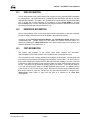
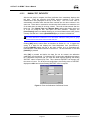
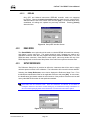
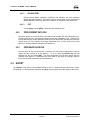
9,(:&$/,%5$7,21&2()),&,(176
Choose this Menu Option to view a snapshot of the complete set of currently active
calibration coefficients for all ranges of the RPM3. This includes: PA/PM, ZOFFSET, and
ZNATERR for each range. All of this information is displayed on the coefficient viewer form.
The options menu is the only Main menu option on this form. In the Options menu are three
sub-menus:
•
Print
•
Re-load
•
Exit
The information displayed can only be viewed and cannot be saved to a file or to the RPM3.
Figure 15. Calibration Information of RPM3 SN: 107
35,17
To print the contents of the view calibration coefficients display to the default printer
select the Print menu option.
3P K XOa Z\SX^O\ S] ]OVOM^ON SX ^RO Z\SX^ NSKVYQ LYb ^RS] Z\SX^O\ S] K_^YWK^SMKVVc
MRKXQON^Y^RONOPK_V^]c]^OWZ\SX^O\
©2000 DH Instruments, Inc.
Page 26
CalTool™ for RPM3™ User’s Manual
5(/2$'530
Reload rereads RPM3 calibration coefficients and refreshes the view calibration
display with that information. This function can be used to obtain current coefficients if
RPM3 calibration coefficients have been changed, for example by front panel entry.
(;,7
Choose [Exit] or press [ESC] to close the view calibration form.
23(1&855(17'$7$),/(
This option allows the current data file to be opened and viewed in the data manipulator form.
The last valid data file is automatically loaded into the data manipulator form. Valid log files
include data files just created, data files resulting from an aborted test and data files previously
viewed using one of the options on the data manipulator form. If there is NO current valid
data file, a message displays stating this (see Section 5).
23(16$9(''$7$),/(
Use this option to view an old data file. At times a user may want to regenerate a report or
simply view the contents of an old data file. To do so, select the desired file from the
displayed file box and press [OK]. The data manipulator form will then display with the
contents of the data file. Functionally, this menu option is the same as opening a data file
from within the data manipulator form (see Section 5).
$%2 57 The <Abort> menu option is only displayed when a test is in progress and all other menu options
are disabled. It is the equivalent of pressing the [Esc] key which gives users the option to abort a test.
Page 27
©2000 DH Instruments, Inc.
CalTool™ for RPM3™ User’s Manual
89>/=
©2000 DH Instruments, Inc.
Page 28
CalTool™ for RPM3™ User’s Manual
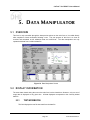
.+>+7+83:?6+>9<
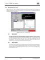
29(59,(:
This form is only accessible through the data preview options on the main form or it is called directly
after completion of data verification following a test. The sole purpose of this form is to view as
received and calculated as left calibration data and coefficients. The data manipulator can only
operated with data from a valid test data file.
Figure 16. Data Manipulator Screen
',63/$<,1)250$7,21
The same data viewed during the test on the main form is also viewed here. However, only one set of
range data is displayed at any given time. All data displayed corresponds to the currently loaded
data file.
7(67,1)250$7,21
This field displays the test file data read from the data file.
Page 29
©2000 DH Instruments, Inc.
CalTool™ for RPM3™ User’s Manual
5()(5(1&(,1)250$7,21
Reference model and identification are also read directly from the data file and displayed on
the form. In many cases the identification string will exceed the length of the display field and
scroll out of view of the user. The information is still there, it just is NOT visible. When reports
are created, the entire identification string will be displayed.
'$7$*5$3+
The graph displays % FS errors for both As Received and Calculated As Left RPM3
readings versus reference pressures in current pressure units. If the user clicks the graph,
it is automatically maximized until it is clicked again or the user presses escape.
530,1)250$7,21
The same RPM3 information is available in the data manipulator form as on the main form.
The major difference is that the display is for the current range only. The first row of the
imprint displays the as received calibration coefficients and the second the new calculated
calibration coefficients.
0(18237,216
),/(0(18
23(1'$7$),/(
Opening a data file gives the user the ability to load any number of existing test
data files. The files can be viewed or used to generate reports. If the data file is valid,
all data is loaded into the display. If an RPM3 is currently remotely connected and its
serial number is the same as the serial number of the data file RPM3, the Calibration
menu is enabled. Otherwise the Menu is disabled to prevent calibration data of one
RPM3 from being saved to another.
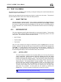
9,(:&855(175(3257
The objective of the report function is to provide a convenient standard report format.
To create your own customized report either open the comma delimited data file and
manipulate it in another program such as Excel, Lotus, etc. or copy the report into a
word processor by cutting and pasting.
When selected, the standard report displays. The report can be edited in any way
desired and saved by using the <Save Report> option. This is NOT a true
report editor, so many typical word processor features are unavailable. To export the
report into a true word processor, select the entire document by clicking the
beginning of the document and holding the mouse button down, then drag it to the
end of the report. Press [Ctrl] + [C] to copy the information to the Windows clipboard.
Paste the information into the desired word processor document. To close the report,
press [Esc] or choose <Return to Data View> which is in place of the
<View Current Report> menu option while the report is visible.
©2000 DH Instruments, Inc.
Page 30
CalTool™ for RPM3™ User’s Manual
Figure 17. Data Manipulator: Calibration Report Screen
9,(:6$9('5(3257
Only reports created by using the <Save Report> option can be viewed. Choose the
desired report from the file box and press [OK]. The report will display in the same
fashion as the previous option.
6$9(5(3257
This choice allows the user to save the report. If edits were made to the report, this
option must be selected while the report is visible for the edits to be saved. When the
report is NOT visible, the default report is always saved. The default name of a report
is the same as the current data file except the file extension is .rpt. Determine the
path and filename of the report on the displayed file box and press [OK] to activate
the save.
35,17&855(175(3257
Select <Print Current Report> to print the default report. If edits were made to
the report, this option must be selected while the report is visible to print the edits.
Otherwise, only the standard report generated from the data file is printed.
3P K XOa Z\SX^O\ S] ]OVOM^ON SX ^RO Z\SX^ NSKVYQ LYb ^RS] Z\SX^O\ S] K_^YWK^SMKVVc
MRKXQON^Y^RONOPK_V^]c]^OWZ\SX^O\>RS]S]^ROMK]OPY\KVVZ\SX^SXQYZ^SYX]aS^RSX
^ROZ\YQ\KW
Page 31
©2000 DH Instruments, Inc.
CalTool™ for RPM3™ User’s Manual
35,176$9('5(3257
Choose the report to print from a standard Windows file box. If the file is a valid report
saved using the <Save Report> option, it is sent to the default Windows printer.
(;,7
Pressing [Exit] closes the data manipulator form and returns control to the main form
of the program. If calibration coefficients are activated to the RPM3, the main form
will re-load RPM3 information and display the current information.
&$/,%5$7,210(18
All items in the calibration menu are unavailable unless there is an RPM3 remotely connected
to the host PC and the data file contains data that corresponds to that RPM3.
$&7,9$7(&$/,%5$7,21
<Activate Calibration> writes the calculated calibration coefficients (PA, PM, and
ZNaterr) and the new calibration date to the RPM3 for the test range. The calibration
date always uses the year month day format (YYYYMMDD). Zoffset is set to zero
after all calibrations except an absolute calibration in gauge mode, this Zoffset value is
NOT modified. A check mark <√> will appear next to any calibration that was
successfully activated. If an error occurs during the activation process, the original
calibration data is restored automatically.
&23<&$/,%5$7,2172
This menu choice is provided to allow the calibration coefficients of a range to be
applied to lower ranges. This is used if one does NOT want to calibrate all the ranges
of an RPT but would like to be sure that they are consistent with each other.
Calibrations can only be copied to lower ranges and NOT to higher ranges because of
the risk of out of tolerance results by extrapolation in the part of a range that is greater
than the calibrated range.
Use <COPY CALIBRATION TO> to apply the current calibration coefficients of a
higher range to lower ranges on the same RPT. If the test range was the lowest
range of an RPT, none will display because there are NO other ranges to apply the
calibration to. Otherwise the other possible ranges are listed. When the desired
range is selected, the current calibration coefficients and date are written to
that range. A check mark <√> will appear next to any calibration that was
successfully activated.
©2000 DH Instruments, Inc.
Page 32
CalTool™ for RPM3™ User’s Manual
5(6725(
<Restore> allows the old RPM3 calibration coefficients to be restored after new
calibration coefficients have been activated so long as the current data file
remains open.
Restore is available after a calibration is activated to the RPM3. Choose <Restore>
when you wish to undo any calibration that was activated. The RPM3 calibration
coefficients are restored back to the values that were replaced when the new
calibration was activated. They are NOT restored to the values recorded in the
data file. Only calibrations activated during the current run of a data file can
be restored. Each time a new data file is opened, the restore option is disabled until a
new calibration is activated. So if a calibration is activated in one data file it cannot be
restored while another data file is open.
9,(:&$/,%5$7,21&2()),&,(176
This option is equivalent to the view calibration coefficients form on the Main menu
(see Section 4.4.1).
237,216
,1&/8'(*5$3+,15(3257
If you want your report to include the graph of the as received and as left errors, make
sure that there is a check mark <√> next to this option. Click on the option to add or
remove the check mark <√>.
Page 33
©2000 DH Instruments, Inc.
CalTool™ for RPM3™ User’s Manual
89>/=
©2000 DH Instruments, Inc.
Page 34
CalTool™ for RPM3™ User’s Manual
-+6-?6+>398=
29(59,(:
This section describes the mathematical manipulation used by CalTool to determine new calibration
coefficients and calculate as left data. The coefficients used include: PA (Pressure Adder),
PM (Pressure Multiplier), ZOFFSET, ZNATERR and ATMOFFSET. All of these values are always
recorded and displayed in Pascal (Pa) pressure units but applied mathematically in the current
measurement units. For more information on these coefficients, see the RPM3 Operation and
Maintenance Manual, CALIBRATION OF REFERENCE PRESSURE TRANSDUCERS, AutoZ.
New calibration coefficients and as left data are determined as described in the following sections.
Data used for calculations is read directly from the selected data file. All data acquired during tests is
simply written to this file without any manipulation regardless of the type of test run. During any
calibration of an absolute RPT in gauge mode, the values of ZOFFSET and ATMOFFSET are also
recorded for every As Received pressure point if AutoZ is ON (see the RPM3 Operation and
Maintenance Manual, AutoZ, PRINCIPLE, Gauge Mode with an Absolute RPT, Dynamic
Compensation for Atmospheric Pressure).
The first step in manipulating any set of calibration coefficients is to determine the RPM3
“factory pressure” for each calibration point (see Section 6.2). The factory pressures are then
regressed against the reference pressures to obtain new PA/PM values (see Section 6.3).
Next, the AutoZ values are modified depending upon the RPT type and measurement mode
(see Section 6.4). Finally, the new PA/PM values are re-applied to the factory pressure to determine
calculated as left pressure and error values.
Page 35
©2000 DH Instruments, Inc.
CalTool™ for RPM3™ User’s Manual
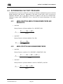
'(7(50,1,1*)$&725<35(6685(
The RPM3 factory pressure is obtained by removing all calibration coefficients from the as received
RPM3 pressures in the data file. Depending on the state of AutoZ (ON or OFF) at the time of
calibration, ZOFFSET may or may NOT be removed. In addition, in the case of an absolute RPT
calibrated in gauge mode, ATMOFFSET may or may NOT be removed depending on the state
of AutoZ.
•
$%62/87(5376,1$%62/87(0($685(0(1702'($1'
*$8*(5376
AutoZ ON
Factory Pressure = (Pressure AsRecd - PA + ZOFFSET) / PM
Pfactory =
•
Pasreceived − PAuser + dPoffset
PMuser
AutoZ OFF
Factory Pressure = (Pressure AsRecd - PA) / PM
Pfactory =
•
Pasreceived − PAuser
PMuser
$%62/87(537,1*$8*(0($685(0(1702'(
AutoZ ON
Factory Pressure = (As Recd - PA + ZOFFSET + ATMOFFSET) / PM
Pfactory =
•
PAsreceived − PAuser + dPoffset + dPAtmOffset
PMuser
AutoZ OFF
Factory Pressure = (Pressure AsRecd - User PA + ZOFFSET) / User PM
Pfactory =
©2000 DH Instruments, Inc.
Pasreceived − PAuser + dPoffset
PMuser
Page 36
CalTool™ for RPM3™ User’s Manual
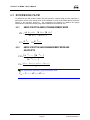
'(7(50,1,1*3$30
To determine the new pressure adder (PA) and pressure multiplier (PM) a linear regression is
performed to arrive at the lowest value of the residuals of errors of the RPM3 factory pressures
relative to the reference pressures. The regressions are different for absolute and gauge
measurement modes because the gauge mode calibrations are biased at zero.
$%62/87(537,1$%62/87(0($685(0(1702'(
PM
=
n∑ PFactoryi PStdi −
PA = ∑
n∑ P
2
Factoryi
PStdi
n
− PM
(∑ P )(∑ P )
− (∑ P
)
Factoryi
Stdi
2
Factoryi
∑P
Factoryi
n
$%62/87(537,1*$8*(0($685(0(1702'($1'
*$8*(5376
PM =
PA =
(∑
P F a c to r y i
(∑
)(∑
PF a c to r y i
)
PS t d i
)
2
( Pstd (1) − Pfactory(1)) + ( Pstd ( n ) − Pfactory( n ))
2
0Y\KL]YV_^O<:>]MKVSL\K^ONSXQK_QOWOK]_\OWOX^WYNO$
PStd
= Preference + dPoffset + dPATMOffset Page 37
©2000 DH Instruments, Inc.
CalTool™ for RPM3™ User’s Manual
=1$7(55=2))6(702',),&$7,216
When new calibration coefficients are activated to the RPM3:
•
For absolute RPTs calibrated in absolute mode, ZOFFSET is set to zero.
•
For gauge RPTs ZOFFSET is set to zero.
•
For absolute RPTs calibrated in gauge mode ZOFFSET is unaffected.
•
For absolute RPTs calibrated in absolute mode, ZNATERR is determined by the predicted
difference between the test and reference at 101.325 kPa.
•
For absolute RPTs calibrated in gauge mode ZNATERR is set to 0.0.
•
ATMOFFSET is unaffected by the calibration process.
'(7(50,1,1*$6/()7'$7$
+L]YV_^O<:>]MKVSL\K^ONSXQK_QOWOK]_\OWOX^WYNOaS^RQK_QO\OPO\OXMOZ\O]]_\O]MKXXY^LO_]ON
PY\KMM_\K^OKL]YV_^OWOK]_\OWOX^]KXN^ROMKVSL\K^SYXaSVV89>cSOVNKMM_\K^OKL]YV_^OK]VOP^NK^K
To determine as left data, the new PA/PM values (Section 6) are applied to the factory pressures to
arrive at the as left pressures. The reference pressures are the same as the as received
reference pressures.
©2000 DH Instruments, Inc.
Page 38