1
xx
ZZZ
TDS5000B Series
Digital Phosphor Oscilloscope
Read This First
www.tektronix.com
*P061433105*
061-4331-05
Copyright © Tektronix. All rights reserved. Licensed software products are owned by Tektronix or its subsidiaries
or suppliers, and are protected by national copyright laws and international treaty provisions.
Tektronix products are covered by U.S. and foreign patents, issued and pending. Information in this publication
supersedes that in all previously published material. Specifications and price change privileges reserved.
TEKTRONIX and TEK are registered trademarks of Tektronix, Inc.
Contacting Tektronix
Tektronix, Inc.
14200 SW Karl Braun Drive
P.O. Box 500
Beaverton, OR 97077
USA
For product information, sales, service, and technical support:
In North America, call 1-800-833-9200.
Worldwide, visit www.tektronix.com to find contacts in your area.
Table of Contents
General Safety Summary ..........................................................................................
Compliance Information ...........................................................................................
EMC Compliance..............................................................................................
Safety Compliance.............................................................................................
Environmental Considerations ...............................................................................
Preface ...............................................................................................................
Quick Start User Manual Information............................................................................
Getting Started .................................................................................................
Operating Requirements ......................................................................................
Powering On the Instrument.................................................................................
Powering Off the Instrument ................................................................................
Removing the Power .........................................................................................
Using Your Instrument .......................................................................................
Standard Accessories .........................................................................................
Service Manual Information......................................................................................
Options.........................................................................................................
Side and Rear Panels .........................................................................................
Cleaning .......................................................................................................
PC Interface Board and Motherboard Cable Connections ...............................................
039-0185-xx Service Information...........................................................................
Replaceable Parts .............................................................................................
Specification and Performance Verification ....................................................................
TDS5000B Read This First
1
2
2
4
6
7
8
8
8
10
10
11
11
11
12
12
12
14
15
17
28
31
i
Table of Contents
ii
TDS5000B Read This First
General Safety Summary
Review the following safety precautions to avoid injury and prevent damage to
this product or any products connected to it.
To avoid potential hazards, use this product only as specified.
To Avoid Fire or Personal
Injury
Use Proper Power Cord. Use only the power cord specified for this product and
certified for the country of use.
Connect and Disconnect Properly. Do not connect or disconnect probes or test
leads while they are connected to a voltage source.
Ground the Product. This product is grounded through the grounding conductor
of the power cord. To avoid electric shock, the grounding conductor must be
connected to earth ground. Before making connections to the input or output
terminals of the product, ensure that the product is properly grounded.
Observe All Terminal Ratings. To avoid fire or shock hazard, observe all ratings
and markings on the product. Consult the product manual for further ratings
information before making connections to the product.
The inputs are not rated for connection to mains or Category II, III, or IV circuits.
Connect the probe reference lead to earth ground only.
Do Not Operate Without Covers. Do not operate this product with covers or
panels removed.
Avoid Exposed Circuitry. Do not touch exposed connections and components
when power is present.
Do Not Operate With Suspected Failures. If you suspect that there is damage to
this product, have it inspected by qualified service personnel.
Do Not Operate in Wet/Damp Conditions.
Do Not Operate in an Explosive Atmosphere.
Keep Product Surfaces Clean and Dry.
Provide Proper Ventilation. Refer to the manual’s installation instructions for
details on installing the product so it has proper ventilation.
Terms in this Manual
These terms may appear in this manual:
WARNING. Warning statements identify conditions or practices that could result
in injury or loss of life.
TDS5000B Read This First
1
Compliance Information
CAUTION. Caution statements identify conditions or practices that could result in
damage to this product or other property.
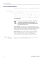
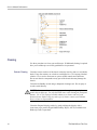
Symbols and Terms on the
Product
These terms may appear on the product:
DANGER indicates an injury hazard immediately accessible as you read
the marking.
WARNING indicates an injury hazard not immediately accessible as you
read the marking.
CAUTION indicates a hazard to property including the product.
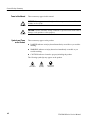
The following symbol(s) may appear on the product:
Compliance Information
This section lists the EMC (electromagnetic compliance), safety, and
environmental standards with which the instrument complies. This EMC section
replaces the Certifications and Compliances section in Table 1–11, of the
TDS5000B Series Technical Reference manual (071-1420-xx).
EMC Compliance
EC Declaration of
Conformity – EMC
Meets intent of Directive 2004/108/EC for Electromagnetic Compatibility.
Compliance was demonstrated to the following specifications as listed in the
Official Journal of the European Communities:
EN 61326-1:2006, EN 61326-2-1:2006. EMC requirements for electrical equipment
for measurement, control, and laboratory use. 1 2 3 4
CISPR 11:2003. Radiated and conducted emissions, Group 1, Class A
IEC 61000-4-2:2001. Electrostatic discharge immunity
IEC 61000-4-3:2002. RF electromagnetic field immunity 5
IEC 61000-4-4:2004. Electrical fast transient/burst immunity
IEC 61000-4-5:2001. Power line surge immunity
IEC 61000-4-6:2003. Conducted RF immunity 5
IEC 61000-4-11:2004. Voltage dips and interruptions immunity 6
2
TDS5000B Read This First
Compliance Information
EN 61000-3-2:2006. AC power line harmonic emissions
EN 61000-3-3:1995. Voltage changes, fluctuations, and flicker
European Contact.
Tektronix UK, Ltd.
Western Peninsula
Western Road
Bracknell, RG12 1RF
United Kingdom
Australia / New Zealand
Declaration of
Conformity – EMC
TDS5000B Read This First
1
This product is intended for use in nonresidential areas only. Use in residential areas may cause electromagnetic
interference.
2
Emissions which exceed the levels required by this standard may occur when this equipment is connected to a
test object.
3
To ensure compliance with the EMC standards listed here, high quality shielded interface cables should be used.
4
Instrument rebooting may be experienced where the EUT takes longer than 10 seconds to recover from IEC
61000-4-11 transient immunity test.
5
Under these conditions, the specifications are amended as follows: 1 mV/division to 1 V/division: < 0.2 division
waveform displacement or < 0.4 division increase in peak -to peak noise for (IEC 61000-4-3 and IEC 61000-4-6
tests)
6
Performance Criterion C applied at the 70%/25 cycle Voltage-Dip and the 0%/250 cycle Voltage-Interruption test
levels (IEC 61000-4-11).
Complies with the EMC provision of the Radiocommunications Act per the
following standard, in accordance with ACMA:
CISPR 11:2003. Radiated and Conducted Emissions, Group 1, Class A, in
accordance with EN 61326-1:2006 and EN 61326-2-1:2006.
3
Compliance Information
Safety Compliance
EC Declaration of
Conformity – Low Voltage
Compliance was demonstrated to the following specification as listed in the
Official Journal of the European Communities:
Low Voltage Directive 2006/95/EC.
EN 61010-1: 2001. Safety requirements for electrical equipment for
measurement control and laboratory use.
U.S. Nationally Recognized
Testing Laboratory Listing
UL 61010B-1. Standard for electrical measuring and test equipment.
Canadian Certification
CAN/CSA-C22.2 No. 61010.1-97. Safety requirements for electrical
equipment for measurement, control, and laboratory use. Part 1.
Additional Compliances
IEC 61010-1: 2001. Safety requirements for electrical equipment for
measurement, control, and laboratory use.
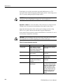
Equipment Type
Safety Class
Pollution Degree
Description
Test and measuring equipment.
Class 1 – grounded product.
A measure of the contaminants that could occur in the environment around
and within a product. Typically the internal environment inside a product is
considered to be the same as the external. Products should be used only in the
environment for which they are rated.
Pollution Degree 2. Normally only dry, nonconductive pollution occurs.
Occasionally a temporary conductivity that is caused by condensation must
be expected. This location is a typical office/home environment. Temporary
condensation occurs only when the product is out of service.
Pollution Degree
4
Pollution Degree 2 (as defined in IEC 61010-1). Note: Rated for indoor use only.
TDS5000B Read This First
Compliance Information
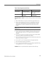
Installation (Overvoltage)
Category Descriptions
Terminals on this product may have different installation (overvoltage) category
designations. The installation categories are:
Measurement Category IV. For measurements performed at the source of
low-voltage installation.
Measurement Category III. For measurements performed in the building
installation.
Measurement Category II. For measurements performed on circuits directly
connected to the low-voltage installation.
Measurement Category I. For measurements performed on circuits not
directly connected to MAINS.
Overvoltage Category
TDS5000B Read This First
Overvoltage Category II (as defined in IEC 61010-1)
5
Compliance Information
Environmental Considerations
This section provides information about the environmental impact of the product.
Product End-of-Life
Handling
Observe the following guidelines when recycling an instrument or component:
Equipment Recycling. Production of this equipment required the extraction and
use of natural resources. The equipment may contain substances that could be
harmful to the environment or human health if improperly handled at the product’s
end of life. In order to avoid release of such substances into the environment and
to reduce the use of natural resources, we encourage you to recycle this product
in an appropriate system that will ensure that most of the materials are reused or
recycled appropriately.
This symbol indicates that this product complies with the applicable European
Union requirements according to Directives 2002/96/EC and 2006/66/EC
on waste electrical and electronic equipment (WEEE) and batteries. For
information about recycling options, check the Support/Service section of the
Tektronix Web site (www.tektronix.com).
Mercury Notification. This product uses an LCD backlight lamp that contains
mercury. Disposal may be regulated due to environmental considerations. Please
contact your local authorities or, within the United States, refer to the E-cycling
Central Web page (www.eiae.org) for disposal or recycling information.
Perchlorate Materials. This product contains one or more type CR lithium
batteries. According to the state of California, CR lithium batteries are
classified as perchlorate materials and require special handling. See
www.dtsc.ca.gov/hazardouswaste/perchlorate for additional information.
Restriction of Hazardous
Substances
6
This product has been classified as Monitoring and Control equipment, and is
outside the scope of the 2002/95/EC RoHS Directive.
TDS5000B Read This First
Preface
Preface
The following information affects the TDS5000B Series Quick Start User manual
and the TDS5000B Series Service manual.
TDS5000B Read This First
7
Quick Start User Manual Information
Quick Start User Manual Information
Getting Started
Use the following information to replace or clarify information contained in your
instrument quick start user manual documentation.
Operating Requirements
Place the bottom feet of the instrument on a cart or bench and observe the
following clearance requirements:
Top, Rear, Front, and Right Side: 0 in (0 mm)
Left Side: 3 in (76 mm)
Bottom: 0.75 in (19 mm) minimum or 0 in (0 mm) standing on feet, flip
stand down
CAUTION. To ensure proper cooling, keep the bottom and sides of the instrument
clear of obstructions.
8
TDS5000B Read This First
Quick Start User Manual Information
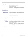
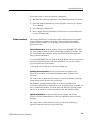
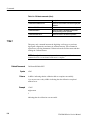
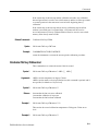
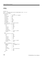
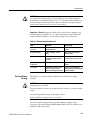
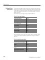
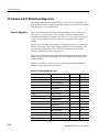
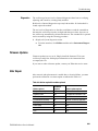
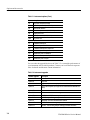
Environmental Requirements
Characteristic
Description
Humidity, operating
20% to 80% relative humidity with a maximum
wet bulb temperature of +29 °C (+84.2 °F) at
or below +45 °C (+113 °F) noncondensing.
Upper limit derated to 30% relative humidity
at +45 °C (+113 °F)
Altitude, operating
9,842 ft. (3,000 m)
Temperature, ambient operating
+5 °C to +45 °C (+41 °F to +113 °F)
Maximum voltage
TDS5000B Read This First
1 MΩ input impedance
150 VRMS CAT I, and ≤400 peak
For steady-state sinusoidal waveforms,
derate at 20 dB/decade above 200 kHz to
9 VRMS at ≥3 MHz
50 Ω input impedance
<1 Vrms for settings below 100 mV/div
<5 Vrms for 100 mV/div settings and above
9
Quick Start User Manual Information
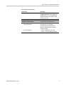
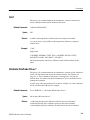
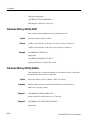
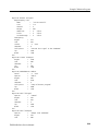
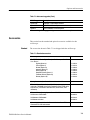
Powering On the Instrument
Power Supply Requirements
Source voltage and frequency
Power consumption
100-240 VRMS ±10%, 47-63 Hz, or
115 VRMS ±10%, 360-440 Hz
<220 watts
WARNING. To avoid fire or shock hazard that could result in injury or loss of life,
observe all ratings and markings on the product. Consult the product manual for
further ratings information before making connections to the product.
Powering Off the Instrument
10
TDS5000B Read This First
Quick Start User Manual Information
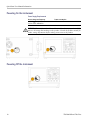
Removing the Power
Using Your Instrument
Documentation for your instrument is found by selecting Help >
Documentation....
Before using your instrument, read the following information in the quick start
user manual:
Safety Summary
Creating an Emergency Startup Disk
Getting Acquainted with Your Instrument
Standard Accessories
The standard accessories list in the TDS5000B Series Quick Start User manual
(071-1355-XX) has been upgraded to include the following discs:
TDS5000B Series Operating System Restore disc (SN B040000 and above)
063-4160-xx.
TDS5000B Series Operating System Restore disc (SN B030000 to B039999)
063-3985-xx.
TDS5000B Series Operating System Restore disc (SN B020000 to SN
B029999) 063-3759-xx
TDS5000B Series Operating System Restore disc (SN B010100 to SN
B019999) 063-3693-xx
NOTE. Only serial numbers below B060100 include a floppy disc.
TDS5000B Read This First
11
Service Manual Information
Service Manual Information
Use the following information to replace or clarify information contained in
your TDS5000B Series Digital Phosphor Oscilloscopes (071-1362-XX) service
manual. This service manual is on the Tektronix Web site.
Options
The TDS5054B and TDS5104B instruments have been upgraded to include the
following options: Option 18 (Touch Screen) and Option 3M (16 M points record
length).
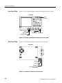
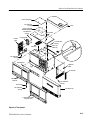
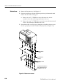
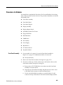
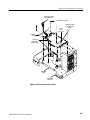
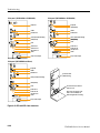
Side and Rear Panels
The following side-panel illustrations (in the Theory of Operation section) have
been upgraded to include the latest component locations and are for reference
only. Use the instructions in the TDS5000B Series Quick Start User manual
(071-1355-XX) to connect your instrument.
12
TDS5000B Read This First
Service Manual Information
TDS5000B Read This First
13
Service Manual Information
Cleaning
Use these procedures to clean your oscilloscope. If additional cleaning is required
have your oscilloscope serviced by qualified service personnel.
Exterior Cleaning
Clean the exterior surfaces of the chassis with a dry lint-free cloth or a soft-bristle
brush. If any dirt remains, use a cloth or swab dipped in a 75% isopropyl alcohol
solution. Use a swab to clean narrow spaces around controls and connectors.
Do not use abrasive compounds on any part of the chassis that may damage the
chassis.
Clean the On/Standby switch using a dampened cleaning towel. Do not spray or
wet the switch directly.
CAUTION. Do not use chemical cleaning agents that might damage the plastics
used in this oscilloscope. Use only deionized water when cleaning the front-panel
buttons. Use a 75% isopropyl alcohol solution as a cleaner and rinse with
deionized water. Before using any other type of cleaner, contact your Tektronix
Service Center or representative.
Clean the flat panel display surface by gently rubbing the display with a
clean-room wipe (such as Wypall Medium Duty Wipes, #05701, available from
Kimberly-Clark Corporation).
14
TDS5000B Read This First
Service Manual Information
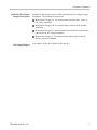
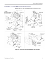
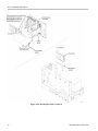
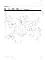
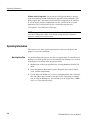
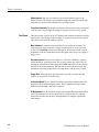
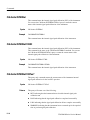
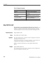
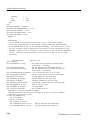
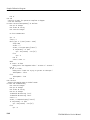
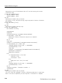
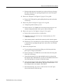
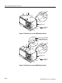
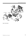
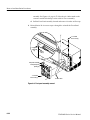
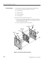
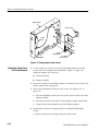
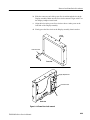
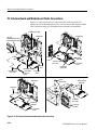
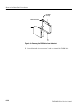
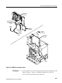
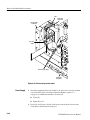
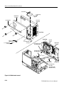
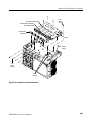
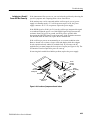
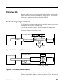
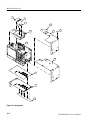
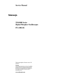
PC Interface Board and Motherboard Cable Connections
Replace Figures 6-17 and 6–18 in the Removal and Installation Procedures).
Figure 6-17: PC Interface board and motherboard cable connections
TDS5000B Read This First
15
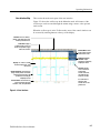
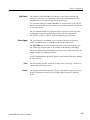
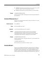
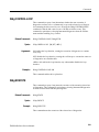
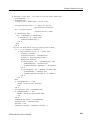
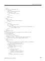
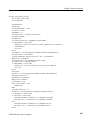
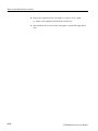
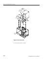
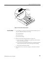
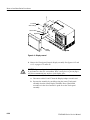
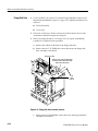
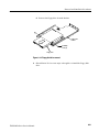
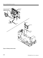
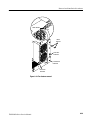
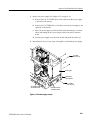
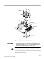
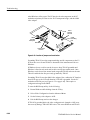
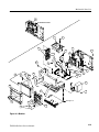
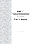
Service Manual Information
Figure 6-18: Desktop hard drive removal
16
TDS5000B Read This First
Service Manual Information
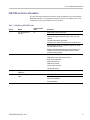
039-0185-xx Service Information
Use the following information when servicing instruments with serial numbers
B040000 and above or instruments using the 039-0185-xx Mother board. This
information is only for qualified service personnel.
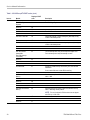
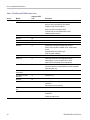
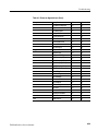
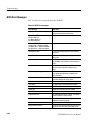
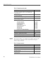
Table 1: 039-0185-xx μATX POST codes
Item no.
Module
1
Turn Off Chipset and
CPU test
Displayed POST
code
Description
C0
OEM Specific-Cache control cache
Processor Status (1FLAGS) Verification
Tests the following processor status flags: Carry, zero, sign,
overflow.
The BIOS sets each flag and verifies.
The flags are set, then turns each flag off and verifies if it is off.
Read/Write/Verify all the CPU registers except SS, SP, and BP
with data pattern FF and 00.
RAM must be periodically refreshed to keep the memory from
decaying. This function ensures that the memory refresh
function is working properly.
2
Memory Presence
C1
First block memory detect
OEM Specific-Test to size on-board memory
Early chip set initialization
Memory presence test
OEM chip set routines
Clear low 64K of memory
Test first 64K memory
3
Early Memory
Initialization
C2
OEM Specific-Board Initialization
4
Extend Memory DRAM
select
C3
OEM Specific-Turn on extended memory
TDS5000B Read This First
Initialization
Cyrix CPU initialization
Cache initialization
17
Service Manual Information
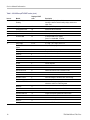
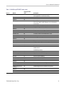
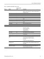
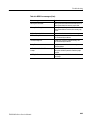
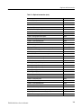
Table 1: 039-0185-xx μATX POST codes, (cont.)
Displayed POST
code
Item no.
Module
5
Special Display
Handling
6
Early Shadow
C5
OEM specific-Early shadow enable for fast boot
7
Cache presence test
C6
External cache size detection
8
CMOS Check
CF
CMOS checkup
9
Spurious
B0
If interrupt occurs in protected mode.
10
Unclaimed NMI
B1
If unmasked NMI occurs, display
Press F1 to disable NMI, F2 reboot.
11
Program Chip Set
BF
To program chipset from defaults values
12
Setup Pages
E1–EF
E1- Page 1, E2 - Page 2, and so on
Force load Default to
chipset
1
Chipset defaults program
Reserved
2
Early Super IO Init
3
Reserved
4
Blank video
5
Reserved
6
Init KBC
7
Keyboard controller init
KB test
8
Test the keyboard
Reserved
9
Mouse Init
A
Initialize the mouse
Onboard Audio init
B
Initialize the onboard audio controller if it exits
Reserved
C
Reserved
D
CheckSum Check
E
Reserved
F
Auto detect EEPROM
10
Reserved
11
CMOS Check
12
Reserved
13
Chipset Default load
14
18
C4
Reserved
15
Clock Init
16
Reserved
17
Identify the CPU
18
Description
OEM Specific-Display/Video Switch
Handling so that the Switch Handling display switch errors
never occur
Early Initialize of the super IO
Reset the Video controller
Check the integrity of the ROM, BIOS, and message
Check the Flash type and copy flash
write/erase routines to 0F000h segments
Check CMOS circuitry and reset CMOS
Program the chipset registers with CMOS values
Init onboard clock generator
Check the CPU ID and init L1/L2 cache
TDS5000B Read This First
Service Manual Information
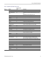
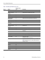
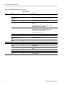
Table 1: 039-0185-xx μATX POST codes, (cont.)
Item no.
Module
Displayed POST
code
12
Reserved
19
Reserved
1A
Setup Interrupt Vector
Table
1B
Reserved
1C
Early PM Init
1D
Reserved
1E
Re-initial KB
1F
Reserved
20
HPM init
21
Reserved
22
Test CMOS Interface
and Battery Status
23
Reserved
24
Reserved
25
Reserved
26
KBC final Init
27
Reserved
28
Initialize Video Interface
29
Reserved
2A
Description
Initialize first 120 interrupt vectors with SPURIOUS_INT_HDLR
and
initialize INT 00h-1Fh according to INT_TBL
First step initialize if single CPU onboard
Re-init KB
If support HPM, HPM get initialized here
Verifies CMOS is working correctly and detects bad battery.
If failed, load CMOS defaults and load into chipset
Final Initial KBC and setup BIOS data area
Read CMOS location 14h to find out type of video in use.
Detect and Initialize Video Adapter.
Reserved
2B
Reserved
2C
Video memory test
2D
Test video memory, write sign-on message to screen.
Setup shadow RAM - Enable shadow according to Setup.
Reserved
2E
Setup shadow RAM - Enable shadow according to Setup.
Reserved
2F
Reserved
30
Reserved
31
Reserved
32
PS2 Mouse setup
33
Reserved
34
Test DMA Controller 0
35
Reserved
36
Test DMA Controller 1
37
TDS5000B Read This First
Setup PS2 Mouse and reset KB
Test DMA channel 0
Test DMA channel 1
19
Service Manual Information
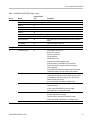
Table 1: 039-0185-xx μATX POST codes, (cont.)
Item no.
Module
Displayed POST
code
12
Reserved
38
Test DMA Page
Registers
39
Reserved
3A
Reserved
3B
Test Timer Counter 2
3C
Reserved
3D
Test 8259-1 Mask Bits
3E
Reserved
3F
Test 8259-2 Mask Bits
40
Reserved
41
Reserved
42
Test Stuck 8259’s
Interrupt Bits
Test 8259 Interrupt
Functionality
43
Reserved
44
Reserved
45
Reserved
46
Set EISA Mode
47
Reserved
48
Size Base and Extended
Memory
49
Reserved
4A
Reserved
4B
Reserved
4C
Reserved
4D
Test Base and Extended
Memory
4E
Description
Test DMA Page Registers.
Test 8254 Timer 0 Counter 2.
Verify 8259 Channel 1 masked interrupts by alternately turning
off and on the interrupt lines.
Verify 8259 Channel 2 masked interrupts by alternately turning
off and on the interrupt lines.
Turn off interrupts then verify no interrupt mask register is on.
Force an interrupt and verify the interrupt occurred.
If EISA non-volatile memory checksum is good, execute EISA
initialization.
If not, execute ISA tests an clear EISA mode flag.
Size base memory from 256 K to 640 K and extended memory
above 1 MB.
Test base memory from 256K to 640K and extended memory
above 1 MB using various patterns.
NOTE. This test is skipped in EISA mode and can be skipped
with ESC key in ISA mode.
20
Reserved
4F
USB init
50
Reserved
51
Initialize USB controller
TDS5000B Read This First
Service Manual Information
Table 1: 039-0185-xx μATX POST codes, (cont.)
Item no.
Module
Displayed POST
code
12
Memory Test
52
Reserved
53
Reserved
54
CPU display
55
Reserved
56
PnP Init
57
Reserved
58
Setup Virus Protect
59
Reserved
5A
Awdflash Load
5B
Reserved
5C
Onboard I/O Init
5D
Reserved
5E
Reserved
5F
Setup enable
60
Reserved
61
Reserved
62
Initialize & Install Mouse
63
Reserved
64
PS2 Mouse special
65
Reserved
66
ACPI init
67
Reserved
68
Setup Cache Controller
69
Reserved
6A
Setup Entering
6B
Reserved
6C
Initialize Floppy Drive &
Controller
6D
Reserved
6E
FDD install
6F
Reserved
70
TDS5000B Read This First
Description
Test all memory of memory above 1 MB using Virtual 8086
mode, page mode, and clear the memory
Detect CPU speed and display
CPU vendor specific version string and turn on all necessary
CPU features
Display PnP logo and PnP early init
Setup virus protect according to Setup
If required, will auto load Awdflash.exe in POST
Initializing onboard super IO
Display setup message and enable setup functions
Detect if mouse is present
initialize mouse
install interrupt vectors
Special treatment to PS2 Mouse port
ACPI sub-system initializing
Initialize cache controller
Enter setup check and auto-configuration check up
Initialize floppy disk drive controller and any drives.
Install FDD and setup BIOS data area parameters
21
Service Manual Information
Table 1: 039-0185-xx μATX POST codes, (cont.)
Item no.
Module
Displayed POST
code
12
Reserved
71
Reserved
72
Initialize Hard Drive &
Controller
73
Reserved
74
Install HDD
75
Reserved
76
Detect & Initialize
Serial/Parallel
77
Reserved
78
Reserved
79
Detect & Initialize Math
Coprocessor
7A
Reserved
7B
HDD Check for Write
protection
7C
Reserved
7D
Reserved
7E
POST error check
7F
Reserved
80
Description
Initialize hard drive controller and any drives.
IDE device detection and install
Initialize any serial and parallel ports (also game port)
Initialize math coprocessor
HDD check out
Check POST error and display them and ask for user
intervention
Reserved
81
Security Check
82
Ask password security (optional)
Write CMOS
83
Write all CMOS values back to RAM and clear screen
Pre-boot Enable
84
Enable parity checker
Enable NMI, enable cache before boot.
Initialize Option ROMs
85
Initialize any option ROMs present from C8000h to EFFFFh.
NOTE. When FSCAN option is enabled, ROMs initialize from
C8000h to F7FFFh.
22
Reserved
86
Reserved
87
Reserved
88
Reserved
89
Reserved
8A
Reserved
8B
Reserved
8C
TDS5000B Read This First
Service Manual Information
Table 1: 039-0185-xx μATX POST codes, (cont.)
Item no.
Module
Displayed POST
code
12
Reserved
8D
Reserved
8E
Reserved
8F
Reserved
90
Reserved
91
Reserved
92
Boot Medium detection
93
Read and store boot partition head and
Final Init
94
Final init for last micro details before boot
Special KBC patch
95
Set system speed for boot Setup NumLock status according to
Setup
Boot Attempt
96
Set low stack Boot via INT 19h.
Boot
FF
Description
Quick POST Codes
13
Init onboard device
65
Early Initialized the super IO
Reset Video controller
Keyboard controller init
Test the Keyboard
Initialized the mouse
Onboard audio controller initialize if exist
Check the integrity of the ROM, BIOS, and message
Check Flash type and copy flash write/erase routines to
0F000h segments
Check CMOS Circuitry and reset CMOS Program the chipset
registers with CMOS values Init onboard clock generator
Early System setup
66
Check the CPU ID and init L1/L2 cache
Initialize first 120 interrupt vectors with SPURIOUS_INT_HDLR
and initialize INT 00h-1Fh according to INT_TBL First step
initialize if single CPU onboard.
Re-init KB If support HPM, HPM get initialized here
KBC and CMOS Init
67
Verifies CMOS is working correctly
detects bad battery
If failed, load CMOS defaults and load into chipset
Final Initial KBC and setup BIOS data area.
Video Init
68
Read CMOS location 14h to find out type of video in use.
Detect and Initialize Video Adapter.
Test video memory, write sign-on message to screen.
Setup shadow RAM - Enable shadow according to Setup.
8259 Init
69
Init 8259 channel 1 and mask IRQ 9
TDS5000B Read This First
23
Service Manual Information
Table 1: 039-0185-xx μATX POST codes, (cont.)
Item no.
Module
Displayed POST
code
Description
13
Memory test
6A
Quick Memory Test
CPU Detect and IO init
6B
Detect CPU speed and display CPU vendor specific version
string and turn on all necessary CPU features
Display PnP logo and PnP early init
Setup virus protect according to Setup.
If required, will auto load Awdflash.exe in POST
Initializing onboard super IO
Reserved
6C
Reserved
6D
Reserved
6E
Reserved
6F
Setup Init
70
Display setup message and enable setup functions
Detect if mouse is present, initialize mouse, install interrupt
vectors
Special treatment to PS2 Mouse port
ACPI sub-system initializing
Setup Cache Controller
71
Initialize cache controller
Install FDD
72
Enter setup check and auto-configuration check up
Initialize floppy disk drive controller and any drives
Install FDD and setup BIOS data area parameters
Install HDD
73
Initialize hard drive controller and any drives
IDE device detection and install Initialize any serial and parallel
ports (also game port)
Detect & Initialize Math
Coprocessor
74
Initialize math coprocessor
HDD Check for Write
protection
75
HDD check out
Reserved
76
Display POST error
77
Check POST error and display them and ask for user
intervention
Ask password security (optional)
CMOS and Option ROM
Init
78
Write all CMOS values back to RAM and clear screen
Enable parity checker
Enable NMI
Enable cache before boot.
24
TDS5000B Read This First
Service Manual Information
Table 1: 039-0185-xx μATX POST codes, (cont.)
Item no.
Module
Displayed POST
code
13
Description
Initialize any option ROMs present from C8000h to EFFFFh
NOTE. When FSCAN option is enabled, ROMs initialize from
C8000h to F7FFFh.
Reserved
79
Reserved
7A
Reserved
7B
Reserved
7C
Boot Medium detection
7D
Read and store boot partition head and cylinders values in
RAM
Final Init
7E
Final init for last micro details before boot
Special KBC patch
7F
Set system speed for boot Setup NumLock status according to
Setup
Boot Attempt
80
Set low stack Boot via INT 19h
Boot
FF
S4 POST Codes
14
Early Chipset Init
5A
Early Initialized the super IO
Reset Video controller
Keyboard controller init
Test the Keyboard
Initialized the mouse
Cmos Check
5B
Check CMOS Circuitry and reset CMOS
Chipset default Prog
5C
Program the chipset registers with CMOS values. Init onboard
clock generator
Identify the CPU
5D
Check the CPU ID and init L1/L2 cache
Setup Interrupt Vector
Table
5E
Initialize first 120 interrupt vectors with SPURIOUS_INT_HDLR
and INT 00h-1Fh according to INT_TBL
First step initialize if single CPU Onboard
Re-init KB
If support HPM, HPM get initialized here.
Test CMOS Interface
and Battery status
5F
Verifies CMOS is working correctly
detects bad battery. If failed, load CMOS defaults and load
into chipset
KBC final Init
60
Final Initial KBC and setup BIOS data area
Initialize Video Interface
61
Read CMOS location 14h to find out type of video in use
Detect and Initialize Video Adapter
TDS5000B Read This First
25
Service Manual Information
Table 1: 039-0185-xx μATX POST codes, (cont.)
Item no.
Module
Displayed POST
code
14
Video memory test
62
Test video memory, write sign-on message to screen
Setup shadow RAM - Enable shadow according to Setup
Setup PS2 mouse and
test DMA
63
Setup PS2 Mouse and reset KB Test DMA channel 0
Test 8259
64
Test 8259 channel 1 and mask IRQ 9
Init Boot Device
65
Detect if mouse is present, initialize mouse, install interrupt
vectors
Special treatment to PS2 Mouse port ACPI sub-system
initializing Initialize cache controller
Install Boot Devices
66
Enter setup check and auto-configuration check up
Initialize floppy disk drive controller and any drives
Install FDD and setup BIOS data area
Parameters Initialize hard drive
Cache Init
67
Cache init and USB init
PM init
68
PM initialization
PM final Init and issue
SMI
69
Final init Before resume
Full on
FF
Description
BootBlock POST Codes
15
26
Base memory test
1
Clear base memory area (0000:0000–9000:ffffh)
KB init
5
Initialized KBC
Install interrupt vectors
12
Install int. vector (0-77) and initialized 00-1fh to their proper
place
Init Video
0D
Video initializing
Init FDD
41
Scan floppy and media capacity for onboard super IO
Boot
FF
Load boot sector
TDS5000B Read This First
Service Manual Information
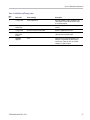
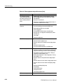
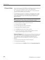
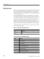
Table 2: 039-0185-xx μATX beep codes
Item
no.
Beep code
Error message
Description
1
1 long, 2 short
Video adapter error
Bad video adapter or a bad connection to the
video adapter. Ensure that the monitor cable
is connected properly.
2
Repeating
endless loop
Memory error
Check for improperly seated or missing
memory.
3
1 long, 3 short
No video card or bad video RAM
Reseat or replace the video card.
4
High frequency
beeps while
running
Overheated CPU
Check the CPU fan for proper operation and
check the case for proper air flow.
5
Repeating
High/Low
CPU
Either the CPU is not seated properly or it is
damaged. The problem can also be due to
excess heat. Check the CPU fan or BIOS
settings for proper fan speed.
TDS5000B Read This First
27
Service Manual Information
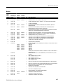
Replaceable Parts
Use the following information to replace or clarify parts list information in the
service manual.
External parts
Fig. &
index
number
Tektronix
part
number
Serial no.
effective
10-1-(not
shown)
101-0158-xx
B030000
Fig. &
index
number
Tektronix
part
number
Serial no.
effective
10-2-10
441-2226-xx
Serial no.
discont’d
Qty
Name & description
1
TRIM RING; FR110,PC/ABS
Serial no.
discont’d
Qty
Name & description
B010100
B019999
1
CHASSIS ASSY;FOR ASHLAND MOTHER BOARD,0.050 AL
W/BRACKETS & HARDWARE
441-2376-xx
B020000
B029999
1
CHASSIS ASSY;FOR LACROSSE MOTHER BOARD,0.050 AL
W/BRACKETS & HARDWARE
441-2491-xx
B030000
B039999
1
CHASSIS ASSY;FOR TAPPEN MOTHER BOARD,0.050 AL
W/BRACKETS & HARDWARE
441-2557-xx
B040000
1
CHASSIS ASSY;FOR ADVANTECH MOTHER BOARD,0.050 AL
W/BRACKETS & HARDWARE
Fig. &
index
number
Tektronix
part
number
Serial no.
effective
Serial no.
discont’d
Qty
Name & description
10-3-5
039-0154-xx
B010100
B019999
1
MOTHER BOARD ASSY;PENTIUM 4/CELERON BD, UATX,ASHLAND
2.1,W/O PROCESSOR,D845GVAD2L
039-0159-xx
B020000
B029999
1
MOTHER BOARD ASSY;PENTIUM 4/CELERON BD, UATX,LA
CROSSE,W/O PROCESSOR,BLKD865GLCLK INTEL P/N,SAFETY
CONTROLLED
039-0173-xx
B030000
B039999
1
MOTHER BOARD ASSY;PENTIUM 4, UATX,TAPPEN
BD,GIG E, PROCESSOR LGA775,DDR2 667MHZ,TOTAL 4
GIG,BLKD945GTPLKR,SAFETY CONTROLLED
039-0185-xx
B040000
1
MOTHER BOARD ASSY;ADVANTECH MICROATX, LGA 775
CORE 2 DUO, DDR2, PCI-E X1, SINGLE GBE LAN; ADVANTECH
AIMB-562VG-00A1E WITH ADD2 DISABLE AND BIOS 562X126N.BIN
SAFETY CONTROLLED
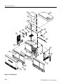
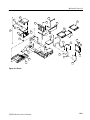
Inner Panels
Modules
28
TDS5000B Read This First
Service Manual Information
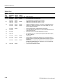
External parts
Fig. &
index
number
Tektronix
part
number
10-4-1
119-7524-xx
4b
174-5639-xx
B040000+
-5
119-6833-xx
B010100
Serial no.
effective
Serial no.
discont’d
B060099
Qty
Name & description
1
DISK DRIVE,HARD; 160GB, 3.5 INCH, 7200 RPM, SATA II 3.0 GB/S
INTERFACE;,SAFETY CONTROLLED
1
CABLE ASSY MOLEX TO SATA POWER ADAPTER
1
DISK DRIVE; USB FLOPPY,3.5 INCH;1.44MB,0.5 INCH,TWO
SIDED,DOUBLE DENSITY,SAFETY CONTROLLED
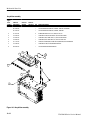
Table 10–4 Drives
TDS5000B Read This First
29
Service Manual Information
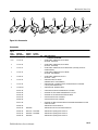
Accessories
Fig. &
index
number
Tektronix
part
number
Serial no.
effective
Serial no.
discont’d
Qty
Name & description
10-6-
063-3693-xx
B010100
B019999
1
TDS5000B SERIES OPERATING SYSTEM RESTORE CD
063-3759-xx
B020000
B029999
1
TDS5000B SERIES OPERATING SYSTEM RESTORE CD
063-3985-xx
B030000
B039999
1
TDS5000B SERIES OPERATING SYSTEM RESTORE CD
020-2969-xx
B040000
1
TDS5000B SERIES OPERATING SYSTEM RESTORE CD KIT
30
TDS5000B Read This First
Specification and Performance Verification
Specification and Performance Verification
Check the TDS5000B Series Digital Phosphor Oscilloscopes Specifications and
Performance Verification (071-1420-XX) manual on the Tektronix Web site for
the latest updates and a complete list of instrument specifications. The Web
site address is located on the copyright page at the front of this Read This First
document.
TDS5000B Read This First
31
Service Manual
TDS5000B Series
Digital Phosphor Oscilloscopes
071-1362-02
Revision A
This document applies to firmware version 1.00
and above.
Warning
The servicing instructions are for use by qualified
personnel only. To avoid personal injury, do not
perform any servicing unless you are qualified to
do so. Refer to all safety summaries prior to
performing service.
www.tektronix.com
Copyright © Tektronix. All rights reserved. Licensed software products are owned by Tektronix or its subsidiaries or
suppliers, and are protected by national copyright laws and international treaty provisions.
Tektronix products are covered by U.S. and foreign patents, issued and pending. Information in this publication supercedes
that in all previously published material. Specifications and price change privileges reserved.
TEKTRONIX and TEK are registered trademarks of Tektronix, Inc.
Contacting Tektronix
Tektronix, Inc.
14200 SW Karl Braun Drive
P.O. Box 500
Beaverton, OR 97077
USA
For product information, sales, service, and technical support:
H In North America, call 1-800-833-9200.
H Worldwide, visit www.tektronix.com to find contacts in your area.
Warranty 2
Tektronix warrants that this product will be free from defects in materials and workmanship for a period of one (1)
year from the date of shipment. If any such product proves defective during this warranty period, Tektronix, at its
option, either will repair the defective product without charge for parts and labor, or will provide a replacement in
exchange for the defective product. Parts, modules and replacement products used by Tektronix for warranty work
may be new or reconditioned to like new performance. All replaced parts, modules and products become the
property of Tektronix.
In order to obtain service under this warranty, Customer must notify Tektronix of the defect before the expiration
of the warranty period and make suitable arrangements for the performance of service. Customer shall be
responsible for packaging and shipping the defective product to the service center designated by Tektronix, with
shipping charges prepaid. Tektronix shall pay for the return of the product to Customer if the shipment is to a
location within the country in which the Tektronix service center is located. Customer shall be responsible for
paying all shipping charges, duties, taxes, and any other charges for products returned to any other locations.
This warranty shall not apply to any defect, failure or damage caused by improper use or improper or inadequate
maintenance and care. Tektronix shall not be obligated to furnish service under this warranty a) to repair damage
resulting from attempts by personnel other than Tektronix representatives to install, repair or service the product;
b) to repair damage resulting from improper use or connection to incompatible equipment; c) to repair any
damage or malfunction caused by the use of non-Tektronix supplies; or d) to service a product that has been
modified or integrated with other products when the effect of such modification or integration increases the time
or difficulty of servicing the product.
THIS WARRANTY IS GIVEN BY TEKTRONIX WITH RESPECT TO THE PRODUCT IN LIEU OF ANY
OTHER WARRANTIES, EXPRESS OR IMPLIED. TEKTRONIX AND ITS VENDORS DISCLAIM ANY
IMPLIED WARRANTIES OF MERCHANTABILITY OR FITNESS FOR A PARTICULAR PURPOSE.
TEKTRONIX’ RESPONSIBILITY TO REPAIR OR REPLACE DEFECTIVE PRODUCTS IS THE SOLE AND
EXCLUSIVE REMEDY PROVIDED TO THE CUSTOMER FOR BREACH OF THIS WARRANTY.
TEKTRONIX AND ITS VENDORS WILL NOT BE LIABLE FOR ANY INDIRECT, SPECIAL, INCIDENTAL,
OR CONSEQUENTIAL DAMAGES IRRESPECTIVE OF WHETHER TEKTRONIX OR THE VENDOR HAS
ADVANCE NOTICE OF THE POSSIBILITY OF SUCH DAMAGES.
Table of Contents
General Safety Summary . . . . . . . . . . . . . . . . . . . . . . . . . . . . . . . . . . .
Service Safety Summary . . . . . . . . . . . . . . . . . . . . . . . . . . . . . . . . . . . .
Environmental Considerations . . . . . . . . . . . . . . . . . . . . . . . . . . . . . . .
Preface . . . . . . . . . . . . . . . . . . . . . . . . . . . . . . . . . . . . . . . . . . . . . . . . . . .
vii
ix
xi
xiii
Manual Structure . . . . . . . . . . . . . . . . . . . . . . . . . . . . . . . . . . . . . . . . . . . . . . . .
Manual Conventions . . . . . . . . . . . . . . . . . . . . . . . . . . . . . . . . . . . . . . . . . . . . . .
Related Documentation . . . . . . . . . . . . . . . . . . . . . . . . . . . . . . . . . . . . . . . . . . .
xiii
xiii
xiv
Installation . . . . . . . . . . . . . . . . . . . . . . . . . . . . . . . . . . . . . . . . . . . . . . . . . . . . .
Before You Start . . . . . . . . . . . . . . . . . . . . . . . . . . . . . . . . . . . . . . . . . . . . .
Environmental Considerations . . . . . . . . . . . . . . . . . . . . . . . . . . . . . . . . . .
Connect the Peripherals . . . . . . . . . . . . . . . . . . . . . . . . . . . . . . . . . . . . . . . .
Power On the Instrument . . . . . . . . . . . . . . . . . . . . . . . . . . . . . . . . . . . . . . .
Powering Off the Oscilloscope . . . . . . . . . . . . . . . . . . . . . . . . . . . . . . . . . .
Create an Emergency Startup Disk . . . . . . . . . . . . . . . . . . . . . . . . . . . . . . .
Software Installation . . . . . . . . . . . . . . . . . . . . . . . . . . . . . . . . . . . . . . . . . .
Operating Information . . . . . . . . . . . . . . . . . . . . . . . . . . . . . . . . . . . . . . . . . . . .
Back Up User Files . . . . . . . . . . . . . . . . . . . . . . . . . . . . . . . . . . . . . . . . . . .
User Interface Map . . . . . . . . . . . . . . . . . . . . . . . . . . . . . . . . . . . . . . . . . . .
Front Panel I/O Map . . . . . . . . . . . . . . . . . . . . . . . . . . . . . . . . . . . . . . . . . .
Rear Panel I/O Map . . . . . . . . . . . . . . . . . . . . . . . . . . . . . . . . . . . . . . . . . . .
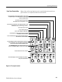
Front Panel Controls Map . . . . . . . . . . . . . . . . . . . . . . . . . . . . . . . . . . . . . .
Instrument Diagnostics . . . . . . . . . . . . . . . . . . . . . . . . . . . . . . . . . . . . . . . .
Signal Path Compensation . . . . . . . . . . . . . . . . . . . . . . . . . . . . . . . . . . . . .
Using the Online Help . . . . . . . . . . . . . . . . . . . . . . . . . . . . . . . . . . . . . . . . .
2-- 1
2-- 1
2-- 1
2-- 2
2-- 4
2-- 4
2-- 4
2-- 5
2-- 6
2-- 6
2-- 7
2-- 8
2-- 8
2-- 9
2-- 10
2-- 10
2-- 11
Logic Conventions . . . . . . . . . . . . . . . . . . . . . . . . . . . . . . . . . . . . . . . . . . . . . . .
Module Overviews . . . . . . . . . . . . . . . . . . . . . . . . . . . . . . . . . . . . . . . . . . . . . . .
3-- 1
3-- 1
Specifications
Operating Information
Theory of Operation
TDS5000B Series Service Manual
i
Table of Contents
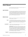
General . . . . . . . . . . . . . . . . . . . . . . . . . . . . . . . . . . . . . . . . . . . . . . . . . . . .
Input Signal Path . . . . . . . . . . . . . . . . . . . . . . . . . . . . . . . . . . . . . . . . . . . . .
Display Panel . . . . . . . . . . . . . . . . . . . . . . . . . . . . . . . . . . . . . . . . . . . . . . . .
Front Panel . . . . . . . . . . . . . . . . . . . . . . . . . . . . . . . . . . . . . . . . . . . . . . . . . .
Side Panels . . . . . . . . . . . . . . . . . . . . . . . . . . . . . . . . . . . . . . . . . . . . . . . . . .
Power Supply . . . . . . . . . . . . . . . . . . . . . . . . . . . . . . . . . . . . . . . . . . . . . . . .
Fans . . . . . . . . . . . . . . . . . . . . . . . . . . . . . . . . . . . . . . . . . . . . . . . . . . . . . . .
Printer . . . . . . . . . . . . . . . . . . . . . . . . . . . . . . . . . . . . . . . . . . . . . . . . . . . . .
3-- 1
3-- 1
3-- 1
3-- 2
3-- 3
3-- 3
3-- 3
3-- 3
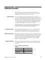
Calibration Interval . . . . . . . . . . . . . . . . . . . . . . . . . . . . . . . . . . . . . . . . . . .
Calibration Environment . . . . . . . . . . . . . . . . . . . . . . . . . . . . . . . . . . . . . . .
Calibration Dependencies . . . . . . . . . . . . . . . . . . . . . . . . . . . . . . . . . . . . . .
Calibration After Repair . . . . . . . . . . . . . . . . . . . . . . . . . . . . . . . . . . . . . . .
Required Equipment . . . . . . . . . . . . . . . . . . . . . . . . . . . . . . . . . . . . . . . . . .
Overview of the Procedure . . . . . . . . . . . . . . . . . . . . . . . . . . . . . . . . . . . . . . . . .
Instrumentation Setup . . . . . . . . . . . . . . . . . . . . . . . . . . . . . . . . . . . . . . . . . . . . .
Calibration Program Installation and Execution . . . . . . . . . . . . . . . . . . . . . . . .
Calibration Program Operation . . . . . . . . . . . . . . . . . . . . . . . . . . . . . . . . . . . . .
5-- 1
5-- 1
5-- 1
5-- 1
5-- 2
5-- 3
5-- 3
5-- 5
5-- 5
Commands . . . . . . . . . . . . . . . . . . . . . . . . . . . . . . . . . . . . . . . . . . . . . . .
5--7
Calibration Command Group . . . . . . . . . . . . . . . . . . . . . . . . . . . . . . . . . . . . . . .
Diagnostics Command Group . . . . . . . . . . . . . . . . . . . . . . . . . . . . . . . . . . . . . .
5-- 7
5-- 19
Sample Calibration Program . . . . . . . . . . . . . . . . . . . . . . . . . . . . . . . .
5--37
Overview . . . . . . . . . . . . . . . . . . . . . . . . . . . . . . . . . . . . . . . . . . . . . . . . . . . . . . .
Listing . . . . . . . . . . . . . . . . . . . . . . . . . . . . . . . . . . . . . . . . . . . . . . . . . . . . . . . . .
5-- 37
5-- 38
Preventing ESD . . . . . . . . . . . . . . . . . . . . . . . . . . . . . . . . . . . . . . . . . . . . . . . . .
Inspection and Cleaning . . . . . . . . . . . . . . . . . . . . . . . . . . . . . . . . . . . . . . . . . . .
General Care . . . . . . . . . . . . . . . . . . . . . . . . . . . . . . . . . . . . . . . . . . . . . . . .
Interior Cleaning . . . . . . . . . . . . . . . . . . . . . . . . . . . . . . . . . . . . . . . . . . . . .
Exterior Cleaning . . . . . . . . . . . . . . . . . . . . . . . . . . . . . . . . . . . . . . . . . . . .
6-- 1
6-- 2
6-- 2
6-- 2
6-- 2
Removal and Installation Procedures . . . . . . . . . . . . . . . . . . . . . . . . .
6--7
Preparation . . . . . . . . . . . . . . . . . . . . . . . . . . . . . . . . . . . . . . . . . . . . . . . . . . . . .
Procedures for External Modules . . . . . . . . . . . . . . . . . . . . . . . . . . . . . . . . . . . .
Procedures for Modules . . . . . . . . . . . . . . . . . . . . . . . . . . . . . . . . . . . . . . . . . . .
PC Interface Board and Motherboard Cable Connections . . . . . . . . . . . . . . . . .
6-- 7
6-- 9
6-- 21
6-- 32
Troubleshooting . . . . . . . . . . . . . . . . . . . . . . . . . . . . . . . . . . . . . . . . . . .
6--51
Service Level . . . . . . . . . . . . . . . . . . . . . . . . . . . . . . . . . . . . . . . . . . . . . . . . . . .
Check for Common Problems . . . . . . . . . . . . . . . . . . . . . . . . . . . . . . . . . . . . . .
Equipment Required . . . . . . . . . . . . . . . . . . . . . . . . . . . . . . . . . . . . . . . . . . . . . .
Fault Isolation Procedure . . . . . . . . . . . . . . . . . . . . . . . . . . . . . . . . . . . . . . . . . .
PC Interface and PC Motherboard Diagnostics . . . . . . . . . . . . . . . . . . . . . . . . .
Firmware Updates . . . . . . . . . . . . . . . . . . . . . . . . . . . . . . . . . . . . . . . . . . . . . . . .
After Repair . . . . . . . . . . . . . . . . . . . . . . . . . . . . . . . . . . . . . . . . . . . . . . . . . . . .
BIOS Error Messages . . . . . . . . . . . . . . . . . . . . . . . . . . . . . . . . . . . . . . . . . . . . .
BIOS Beep Codes . . . . . . . . . . . . . . . . . . . . . . . . . . . . . . . . . . . . . . . . . . . . . . . .
PC Interface LEDs . . . . . . . . . . . . . . . . . . . . . . . . . . . . . . . . . . . . . . . . . . . . . . .
6-- 51
6-- 51
6-- 53
6-- 53
6-- 58
6-- 61
6-- 61
6-- 62
6-- 64
6-- 65
Performance Verification
Calibration Procedure
Maintenance
ii
TDS5000B Series Service Manual
Table of Contents
Troubleshooting Using Reset Circuits . . . . . . . . . . . . . . . . . . . . . . . . . . . . . . . .
Installing the PC Motherboard Serial Number . . . . . . . . . . . . . . . . . . . . . . . . . .
Update/Restore the PC Motherboard CMOS . . . . . . . . . . . . . . . . . . . . . . . . . . .
Installing an Authorization Key . . . . . . . . . . . . . . . . . . . . . . . . . . . . . . . . . . . . .
Hard Disk Drive Maintenance . . . . . . . . . . . . . . . . . . . . . . . . . . . . . . . . . . . . . .
6-- 65
6-- 69
6-- 69
6-- 70
6-- 70
Repackaging Instructions . . . . . . . . . . . . . . . . . . . . . . . . . . . . . . . . . . .
6--71
Packaging . . . . . . . . . . . . . . . . . . . . . . . . . . . . . . . . . . . . . . . . . . . . . . . . . . . . . .
Shipping to the Service Center . . . . . . . . . . . . . . . . . . . . . . . . . . . . . . . . . . . . . .
6-- 71
6-- 71
Options and Accessories
Options . . . . . . . . . . . . . . . . . . . . . . . . . . . . . . . . . . . . . . . . . . . . . . . . . . . . . . . .
Accessories . . . . . . . . . . . . . . . . . . . . . . . . . . . . . . . . . . . . . . . . . . . . . . . . . . . . .
7-- 1
7-- 3
Symbols . . . . . . . . . . . . . . . . . . . . . . . . . . . . . . . . . . . . . . . . . . . . . . . . . . . . . . .
9-- 1
Parts Ordering Information . . . . . . . . . . . . . . . . . . . . . . . . . . . . . . . . . . . . . . . . .
Using the Replaceable Mechanical Parts List . . . . . . . . . . . . . . . . . . . . . . . . . .
10-- 1
10-- 1
Electrical Parts List
Diagrams
Mechanical Parts List
TDS5000B Series Service Manual
iii
Table of Contents
List of Figures
iv
Figure 2--1: Locations of peripheral connectors on the side panel . .
Figure 2--2: On/Standby switch location . . . . . . . . . . . . . . . . . . . . . . .
Figure 2--3: User interface . . . . . . . . . . . . . . . . . . . . . . . . . . . . . . . . . . .
Figure 2--4: Locations of input/output connectors on the front panel
Figure 2--5: Locations of connectors on the rear panel . . . . . . . . . . .
Figure 2--6: Front panel controls . . . . . . . . . . . . . . . . . . . . . . . . . . . . .
2--3
2--4
2--7
2--8
2--8
2--9
Figure 5--1: Calibration setup . . . . . . . . . . . . . . . . . . . . . . . . . . . . . . . .
5--3
Figure 6--1: Knob removal . . . . . . . . . . . . . . . . . . . . . . . . . . . . . . . . . .
Figure 6--2: Trim removal . . . . . . . . . . . . . . . . . . . . . . . . . . . . . . . . . . .
Figure 6--3: Bottom cover removal . . . . . . . . . . . . . . . . . . . . . . . . . . . .
Figure 6--4: Right-side cover removal (SN B030000 and above) . . . .
Figure 6--5: Right-side cover removal (SN B029999 and below) . . . .
Figure 6--6: Printer frame removal . . . . . . . . . . . . . . . . . . . . . . . . . . .
Figure 6--7: Internal modules . . . . . . . . . . . . . . . . . . . . . . . . . . . . . . . .
Figure 6--8: Front panel assembly removal . . . . . . . . . . . . . . . . . . . . .
Figure 6--9: J1 flex cable connector removal . . . . . . . . . . . . . . . . . . . .
Figure 6--10: Front panel board and keyboard removal . . . . . . . . . .
Figure 6--11: Display removal . . . . . . . . . . . . . . . . . . . . . . . . . . . . . . . .
Figure 6--12: Touch panel and Display assembly removal . . . . . . . . .
Figure 6--13: Display adapter board removal . . . . . . . . . . . . . . . . . . .
Figure 6--14: Power flex circuit removal . . . . . . . . . . . . . . . . . . . . . . .
Figure 6--15: Floppy disk drive assembly removal . . . . . . . . . . . . . . .
Figure 6--16: Floppy disk drive removal . . . . . . . . . . . . . . . . . . . . . . .
Figure 6--17: PC Interface board and motherboard cable
connections . . . . . . . . . . . . . . . . . . . . . . . . . . . . . . . . . . . . . . . . . . . .
Figure 6--18: Desktop hard drive removal . . . . . . . . . . . . . . . . . . . . . .
Figure 6--19: Removing the CDRW drive from the bracket . . . . . . .
Figure 6--20: CDRW drive assembly removal . . . . . . . . . . . . . . . . . . .
Figure 6--21: Fan fastener removal . . . . . . . . . . . . . . . . . . . . . . . . . . .
Figure 6--22: Disconnecting the fan cables . . . . . . . . . . . . . . . . . . . . .
Figure 6--23: Power supply removal . . . . . . . . . . . . . . . . . . . . . . . . . . .
Figure 6--24: Motherboard removal . . . . . . . . . . . . . . . . . . . . . . . . . . .
Figure 6--25: Heatsink fan and microprocessor removal . . . . . . . . .
Figure 6--26: PC interface board removal . . . . . . . . . . . . . . . . . . . . . .
6--10
6--13
6--14
6--16
6--16
6--18
6--19
6--22
6--23
6--24
6--26
6--27
6--28
6--29
6--30
6--31
6--32
6--34
6--36
6--37
6--39
6--40
6--41
6--44
6--45
6--47
TDS5000B Series Service Manual
Table of Contents
Figure 6--27: Acquisition circuit board removal . . . . . . . . . . . . . . . . .
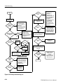
Figure 6--28: Primary troubleshooting tree . . . . . . . . . . . . . . . . . . . . .
Figure 6--29: Location of jumpers and reset button . . . . . . . . . . . . . .
Figure 6--30: The PCI busses (SN B030000 and above) . . . . . . . . . . .
Figure 6--31: The PCI busses (SN B029999 and below) . . . . . . . . . . .
Figure 6--32: Location of jumpers and reset button . . . . . . . . . . . . . .
Figure 6--33: PCI and AGP video connectors . . . . . . . . . . . . . . . . . . .
6--49
6--54
6--55
6--65
6--65
6--66
6--68
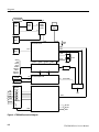
Figure 9--1: TDS5000B series block diagram . . . . . . . . . . . . . . . . . . .
9--2
Figure 10--1: External parts . . . . . . . . . . . . . . . . . . . . . . . . . . . . . . . . .
Figure 10--2: Inner panels . . . . . . . . . . . . . . . . . . . . . . . . . . . . . . . . . . .
Figure 10--3: Modules . . . . . . . . . . . . . . . . . . . . . . . . . . . . . . . . . . . . . .
Figure 10--4: Drives . . . . . . . . . . . . . . . . . . . . . . . . . . . . . . . . . . . . . . . .
Figure 10--5: Acquisition assembly . . . . . . . . . . . . . . . . . . . . . . . . . . . .
Figure 10--6: Accessories . . . . . . . . . . . . . . . . . . . . . . . . . . . . . . . . . . . .
10--4
10--6
10--9
10--11
10--12
10--13
TDS5000B Series Service Manual
v
Table of Contents
List of Tables
vi
Table 2--1: Additional accessory connection information . . . . . . . . .
2--2
Table 5--1: Calibration required for module replaced . . . . . . . . . . .
Table 5--2: Required equipment and materials . . . . . . . . . . . . . . . . .
Table 5--3: GPIB devices required by test program . . . . . . . . . . . . .
Table 5--4: CALibrate commands . . . . . . . . . . . . . . . . . . . . . . . . . . . .
Table 5--5: DIAgnostic Commands . . . . . . . . . . . . . . . . . . . . . . . . . . . .
5--1
5--2
5--5
5--7
5--19
Table 6--1: External inspection check list . . . . . . . . . . . . . . . . . . . . . .
Table 6--2: Internal inspection check list . . . . . . . . . . . . . . . . . . . . . .
Table 6--3: Tools required for module removal . . . . . . . . . . . . . . . . .
Table 6--4: Failure symptoms and possible causes . . . . . . . . . . . . . . .
Table 6--5: Power supply voltages . . . . . . . . . . . . . . . . . . . . . . . . . . . .
Table 6--6: Acquisition board voltages . . . . . . . . . . . . . . . . . . . . . . . .
Table 6--7: Power-on diagnostic tests . . . . . . . . . . . . . . . . . . . . . . . . .
Table 6--8: Action required for module replaced . . . . . . . . . . . . . . . .
Table 6--9: BIOS Error messages . . . . . . . . . . . . . . . . . . . . . . . . . . . .
Table 6--10: Beep codes (SNB030000 and above) . . . . . . . . . . . . . . . .
Table 6--11: Beep codes (SN B010100 to B029999) . . . . . . . . . . . . . .
6--3
6--4
6--8
6--51
6--56
6--56
6--58
6--61
6--62
6--64
6--64
Table 7--1: Instrument options . . . . . . . . . . . . . . . . . . . . . . . . . . . . . . .
Table 7--2: Instrument upgrades . . . . . . . . . . . . . . . . . . . . . . . . . . . . .
Table 7--3: Standard accessories . . . . . . . . . . . . . . . . . . . . . . . . . . . . .
Table 7--4: Optional accessories . . . . . . . . . . . . . . . . . . . . . . . . . . . . . .
7--1
7--2
7--3
7--4
TDS5000B Series Service Manual
General Safety Summary
Review the following safety precautions to avoid injury and prevent damage to
this product or any products connected to it.
To avoid potential hazards, use this product only as specified.
Only qualified personnel should perform service procedures.
While using this product, you may need to access other parts of a larger system.
Read the safety sections of the other component manuals for warnings and
cautions related to operating the system.
To Avoid Fire or
Personal Injury
Use Proper Power Cord. Use only the power cord specified for this product and
certified for the country of use.
Connect and Disconnect Properly. Do not connect or disconnect probes or test
leads while they are connected to a voltage source.
Ground the Product. This product is grounded through the grounding conductor
of the power cord. To avoid electric shock, the grounding conductor must be
connected to earth ground. Before making connections to the input or output
terminals of the product, ensure that the product is properly grounded.
Observe All Terminal Ratings. To avoid fire or shock hazard, observe all ratings
and markings on the product. Consult the product manual for further ratings
information before making connections to the product.
Power Disconnect. The power cord disconnects the product from the power
source. Do not block the power cord; it must remain accessible to the user at all
times.
Do Not Operate Without Covers. Do not operate this product with covers or panels
removed.
Do Not Operate With Suspected Failures. If you suspect there is damage to this
product, have it inspected by qualified service personnel.
Avoid Exposed Circuitry. Do not touch exposed connections and components
when power is present.
Use Proper Fuse. Use only the fuse type and rating specified for this product.
Do Not Operate in Wet/Damp Conditions.
Do Not Operate in an Explosive Atmosphere.
Keep Product Surfaces Clean and Dry.
Provide Proper Ventilation. Refer to the manual’s installation instructions for
details on installing the product so it has proper ventilation.
TDS5000B Series Service Manual
vii
General Safety Summary
Terms in this Manual
These terms may appear in this manual:
WARNING. Warning statements identify conditions or practices that could result
in injury or loss of life.
CAUTION. Caution statements identify conditions or practices that could result in
damage to this product or other property.
Symbols and Terms
on the Product
These terms may appear on the product:
H
DANGER indicates an injury hazard immediately accessible as you read the
marking.
H
WARNING indicates an injury hazard not immediately accessible as you
read the marking.
H
CAUTION indicates a hazard to property including the product.
The following symbol(s) may appear on the product:
CAUTION
Refer to Manual
viii
WARNING
High Voltage
Protective Ground
(Earth) Terminal
TDS5000B Series Service Manual
Service Safety Summary
Only qualified personnel should perform service procedures. Read this Service
Safety Summary and the General Safety Summary before performing any service
procedures.
Do Not Service Alone. Do not perform internal service or adjustments of this
product unless another person capable of rendering first aid and resuscitation is
present.
Disconnect Power. To avoid electric shock, switch off the instrument power, then
disconnect the power cord from the mains power.
Use Care When Servicing With Power On. Dangerous voltages or currents may
exist in this product. Disconnect power, remove battery (if applicable), and
disconnect test leads before removing protective panels, soldering, or replacing
components.
To avoid electric shock, do not touch exposed connections.
TDS5000B Series Service Manual
ix
Service Safety Summary
x
TDS5000B Series Service Manual
Environmental Considerations
This section provides information about the environmental impact of the
product.
Product End-of-Life
Handling
Observe the following guidelines when recycling an instrument or component:
Equipment Recycling. Production of this equipment required the extraction and
use of natural resources. The equipment may contain substances that could be
harmful to the environment or human health if improperly handled at the
product’s end of life. In order to avoid release of such substances into the
environment and to reduce the use of natural resources, we encourage you to
recycle this product in an appropriate system that will ensure that most of the
materials are reused or recycled appropriately.
The symbol shown to the left indicates that this product
complies with the European Union’s requirements
according to Directive 2002/96/EC on waste electrical and
electronic equipment (WEEE). For information about
recycling options, check the Support/Service section of the
Tektronix Web site (www.tektronix.com).
Mercury Notification. This product uses an LCD backlight lamp that contains
mercury. Disposal may be regulated due to environmental considerations. Please
contact your local authorities or, within the United States, the Electronics
Industries Alliance (www.eiae.org) for disposal or recycling information.
Restriction of Hazardous
Substances
This product has been classified as Monitoring and Control equipment, and is
outside the scope of the 2002/95/EC RoHS Directive. This product is known to
contain lead, cadmium, mercury, and hexavalent chromium.
TDS5000B Series Service Manual
xi
Environmental Considerations
xii
TDS5000B Series Service Manual
Preface
This manual contains service information for TDS5000B Series Digital
Phosphor Oscilloscopes. Read this preface to learn how this manual is structured, the conventions it uses, and where to find additional supplemental
information related to servicing this product.
You should also read the General and Service safety summaries before servicing
the product.
Manual Structure
This manual is divided into chapters, which are made up of related subordinate
topics. These topics can be cross referenced as sections.
Be sure to read the introductions to all procedures. These introductions provide
important information needed to do the service correctly, safely, and efficiently.
Manual Conventions
This manual uses certain conventions that you should become familiar with
before attempting service.
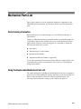
Modules
Throughout this manual, any replaceable component, assembly, or part is
referred to by the term module. A module is composed of electrical and
mechanical assemblies, circuit cards, interconnecting cables, and user-accessible
controls.
Replaceable Parts
This manual refers to any field-replaceable assembly or mechanical part
specifically by its name or generically as a replaceable part. In general, a
replaceable part is any circuit board or assembly, such as the hard disk drive, or a
mechanical part, such as the I/O port connectors, that is listed in the replaceable
parts list of Chapter 10.
Safety
Symbols and terms related to safety appear in the Service Safety Summary found
at the beginning of this manual.
TDS5000B Series Service Manual
xiii
Preface
Related Documentation
TDS5000B Series Digital Phosphor Oscilloscopes ship with the following
additional manuals and CD-ROMs:
xiv
H
TDS5000B Series Digital Phosphor Oscilloscopes Quick Start User Manual
H
Getting Started with OpenChoice Solutions Manual with CD
H
TDS5000B Series Product Software CD. Includes: application, online help,
TDS5000B Series Programmer Online Guide (GPIB online help and PDF),
Performance Verification PDF, release notes, VISA information.
H
TDS5000B Series Elo Touchscreen Switcher Software CD. Refer to the
instructions in the CD booklet that came with the Touch Screen Switcher
Tool CD.
H
TDS5000B Series Operating System Restore CD
H
Optional Applications Software for Windows-Based Oscilloscopes
TDS5000B Series Service Manual
Specifications
Specifications
The specifications for this instrument are now available on the TDS5000B Series
Product Software CD-ROM that shipped with your product.
Look for the TDS5000B Series Digital Phosphor Oscilloscopes Specifications
and Performance Verification Technical Reference PDF, available on this disk.
TDS5000B Series Service Manual
1- 1
Specifications
1- 2
TDS5000B Series Service Manual
Operating Information
Operating Information
This chapter covers installation information and basic operation instructions.
Installation
The basic operating software is already installed on the hard disk. Refer to
Software Installation on page 2--5 for instructions on reinstalling the software.
NOTE. To avoid rebuilding your hard disk, be sure to create an emergency
startup disk. You will need this disk if you ever have to reinstall the Windows
operating system. Refer to Create an Emergency Startup Disk on page 2--4.
Before You Start
Environmental
Considerations
Verify that all parts and accessories for the oscilloscope are available. Use the
graphical packing list that came with the oscilloscope to determine the necessary
parts and accessories. You should also verify that the following items are
available:
H
The correct power cords
H
The product-software CD set that includes installation copies of the software
installed on the oscilloscope
H
All the accessories necessary to operate the oscilloscope
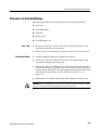
The oscilloscope is designed to operate on a bench or on a cart in the normal
position (on the bottom feet). For proper cooling, at least three inches (7.62 cm)
of clearance is required on the left side of the oscilloscope. If you operate the
oscilloscope while it is resting on the rear feet, make sure that you properly route
any cables coming out of the rear of the oscilloscope to avoid damaging them.
CAUTION. To prevent overheating the oscilloscope, keep the bottom and sides of
the oscilloscope clear of obstructions to ensure proper cooling.
TDS5000B Series Service Manual
2- 1
Operating Information
NOTE. The Power Source and Environmental specifications tables list the
operating requirements for the oscilloscope. Power source, temperature,
humidity, and altitude are listed.
These tables are part of the TDS5000B Series Digital Phosphor Oscilloscopes
Specifications and Performance Verification Technical Reference PDF, available
on the TDS5000B Series Product Software CD-ROM (Tektronix part number
063-3692-xx).
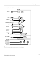
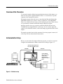
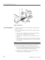
Connect the Peripherals
The peripheral connections are the same as those you would make on a personal
computer. The connection points are shown in Figure 2--1 on page 2--3. See
Table 2--1 for additional connection information.
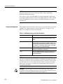
Table 2- 1: Additional accessory connection information
Item
Description
Monitor
If you use a non-standard monitor, you may need to change the
the display settings to achieve the proper resolution for your
monitor.
External Printer
Connect the printer to the EPP (enhanced parallel port)
connector directly. If your printer has a DB-25 connector, use
the adapter cable that came with your printer to connect to the
EPP connector. For information on printer usage, see Printing
Waveforms in your user oscilloscope manual.
Rackmount
Refer to the TDS5000B Rackmount Installation Instructions for
information on installing the rackmount kit.
Other
Refer to the Application release notes on your product CD set
for possible additional accessory installation information not
covered in this manual.
NOTE. We recommend that you plug USB devices directly into the USB connectors on the oscilloscope chassis for improved reliability rather than connecting
the devices serially in a chain. If your mouse locks up, disconnect and reconnect
the USB connector to restore normal operation. If the oscilloscope front panel
and/or touch screen do not respond, press the On/Standby switch for at least
5 seconds to cycle power.
WARNING. To prevent injury to yourself or the oscilloscope, power off the
oscilloscope. before installing accessories (such as the mouse and keyboard) to
connectors. See Powering Off the Oscilloscope on page 2--4.
2- 2
TDS5000B Series Service Manual
Operating Information
Description
Icon/Label
Locations
Side panel
Keyboard
COM 1
Parallel Port
Video (Extended
Desktop)
LAN
USB (Mouse)
Microphone in
Audio line out
Audio line in
GPIB
Scope VGA Output
Rear panel
Trigger signal
output (AUX OUT)
Timebase reference
input (EXT REF)
CH 3 signal output
(SIGNAL OUT)
Figure 2- 1: Locations of peripheral connectors on the side panel
TDS5000B Series Service Manual
2- 3
Operating Information
Power On the Instrument
Follow these steps to power on the instrument.
CAUTION. To prevent damage to the oscilloscope, connect the keyboard, mouse,
and other accessories before applying power to the product.
1. Connect the power cord.
2. If you have an external monitor, connect the power cord and power on the
monitor.
3. Press the On/Standby switch to power on the instrument (see Figure 2--2 for
the switch location).
4. Wait for the boot routine and low-level self test to complete.
Switch
Figure 2- 2: On/Standby switch location
Powering Off the
Oscilloscope
The oscilloscope has a built-in soft power-off function that safely powers off the
oscilloscope when you press the On/Standby switch.
To completely remove power to the instrument, press the On/Standby switch,
and then remove the power cord from the rear panel.
Create an Emergency
Startup Disk
Now that you have completed the basic installation process, you should create an
emergency startup disk that you can use to restart your instrument in case of a
major hardware or software failure. You should create this disk, and then store it
in a safe place.
CAUTION. To prevent rebuilding the entire instrument hard disk, create an
emergency startup disk and store it in a safe place. This disk may allow you to
recover your Windows installation.
The emergency startup disk contains basic files to restart your instrument. It also
contains files to check and format the hard disk.
2- 4
TDS5000B Series Service Manual
Operating Information
Follow these steps to create the emergency startup disk:
1. Minimize the oscilloscope application: select Minimize from the File menu.
2. Select the Windows Start button, point to Programs >Accessories > System
Tools > Backup.
3. Select Emergency Repair Disk.
4. Insert a floppy disk into the disk drive and follow the on-screen instructions
to create the startup disk.
Software Installation
This section describes how to install the system software found on the productsoftware CD that accompanies this product. The instrument ships with the
product software installed, so only perform these procedures if reinstallation
becomes necessary.
Software Release Notes. Read the software release notes README.TXT ASCII
file on the product-software CD before performing installation procedures. This
file contains additional installation and operation information that supercedes
other product documentation.
To view the README.TXT file, open the Notepad Windows accessory and open
the file on the product-software CD. After installation, you can also read the
copy from a directory on the product:
C:\Program Files\Tektronix\TekScope\readme.txt
Operating System Restoration. Use the procedure that accompanies your
Operating System Restore CD should reinstalling system software become
necessary.
The compact disc contains the files necessary to restore the Windows operating
system and necessary drivers for the oscilloscope.
The Windows operating system and drivers are factory installed on the
oscilloscope hard disk. The compact disc serves as a backup in the event that you
have to rebuild the hard drive. You must restore the Windows operating system
before you can install the oscilloscope firmware and other product software.
Application Installation. Use the procedures that accompany your Product
Software CD should reinstalling the oscilloscope application software become
necessary.
The compact disc contains the files necessary to restore the oscilloscope
application and other software for the oscilloscope.
TDS5000B Series Service Manual
2- 5
Operating Information
Software Lock for Upgrades. You can use the LockUpgrades utility to prevent
users from installing unauthorized firmware upgrades on the instrument. This
utility requires that a user enter a password before an upgrade can be installed.
To use the utility, run the LockUpgrades.exe file, and follow the on-screen
instructions. The LockUpgrades.exe file is in the following directory:
C:\Program Files\Tektronix\TekScope
NOTE. Using the Operating System Restore CD to reinstall the operating system
resets the LockUpgrades utility to the default setting and allows firmware
upgrades without password protection.
Operating Information
This section covers basic operation information so that you can operate and
prepare to service the instrument.
Back Up User Files
You should always back up your user files on a regular basis. Use the Microsoft
Backup tool to back up files stored on the hard disk. The Backup tool is located
in the System Tools folder in the Accessories folder.
1. Minimize the oscilloscope application by selecting Minimize from the File
menu.
2. Select the Windows Start button, point to Programs, Accessories, System
Tools, and then click Backup.
3. Use the Microsoft Backup tool to select your backup media and to select the
files and folders that you want to back up. Use the online help for information on using the Backup tool. You can back up to the floppy drive, CDRW
drive, or to your network storage.
2- 6
TDS5000B Series Service Manual
Operating Information
User Interface Map
This section shows the main parts of the user interface.
Figure 2--3 shows the oscilloscope in the Menu bar mode. All features of the
oscilloscope can be accessed through the menus using a mouse or the optional
touch screen.
When the oscilloscope is in the Toolbar mode, most of the control windows can
be accessed by touching buttons at the top of the display.
Menu Bar: Access to data I/O,
printing, online help system, and
oscilloscope functions here
Status Bar: Display of
acquisition status, mode, and
number of acquisitions; trigger
status; date; and time
Buttons/Menu. Click to
toggle between tool-bar
and menu-bar modes
Display: Live, reference, & math
waveforms display here, along
with cursors
Waveform Handle: Click and drag to
change vertical position of waveform.
Click the handle and change the
position and scale using the
multipurpose knobs
Controls Status: Quick reference to
vertical, horizontal, and trigger
selections, scale, and parameters
Multipurpose Knob
Readouts. Adjust
parameters controlled by
multipurpose knobs
Readouts: Display
cursor readouts and
measurement
readouts in this area,
selectable from the
menu bar or toolbar
If a control menu is
displayed, these
readouts move to the
graticule area
Figure 2- 3: User interface
TDS5000B Series Service Manual
2- 7
Operating Information
Front Panel I/O Map
Figure 2--4 shows the input/output connectors and floppy disk drive location.
Front panel
Floppy
disk drive
Auxiliary
trigger input
Channel inputs Ground terminal
Probe comp output
Figure 2- 4: Locations of input/output connectors on the front panel
Rear Panel I/O Map
Figure 2--5 shows the input/output connectors on the rear panel.
Rear panel
EXT REF
AUX OUT
SIGNAL OUT
scale and offset controlled
by CH3 controls
Figure 2- 5: Locations of connectors on the rear panel
2- 8
TDS5000B Series Service Manual
Operating Information
Front Panel Controls Map
Many of the oscilloscope functions can be controlled directly from the front
panel controls or in conjunction with the screen interface.
Use these buttons to start and stop acquisition or start a single
acquisition sequence. The ARM, READY, and TRIG’D lights
show the acquisition status.
Turn knob to adjust waveform intensity.
Press button to turn Fast Acquisition on or off.
Use these knobs and buttons to set the trigger parameters. Push
ADVANCED to display additional trigger functions.
Press to turn cursors on or off.
Press to make a hard copy.
Press to return settings to default values.
Horizontally scale, position, delay, and set record length
(resolution) of selected waveform.
Press to automatically set up the vertical, horizontal, and trigger
controls based on selected channels.
Turn the multipurpose knobs to adjust parameters selected from
the screen interface. Press a Fine button to toggle between
normal and fine adjustment with its multipurpose knob.
Press MultiView Zoom to add a magnified graticule to the
display. Press HORIZ or VERT to select the axis to magnify.
Press to turn the touch screen on and off.
Turn channel displays on and off. Vertically scale, position, or
change the input termination.
Figure 2- 6: Front panel controls
TDS5000B Series Service Manual
2- 9
Operating Information
Instrument Diagnostics
Do the following steps to verify the instrument passes the internal diagnostics.
1. Display the diagnostics menu:
H
If the oscilloscope is in toolbar mode, click the MENU button to put the
oscilloscope into the menu bar mode.
H
Select Instrument Diagnostics . . . from the Utility menu.
2. Run the diagnostics.
H
First disconnect any input signals from all four channels.
H
Click the Run button in the diagnostics control window.
3. Wait for the diagnostics to complete.
The internal diagnostics do an exhaustive verification of proper
oscilloscope function. This verification may take several minutes to
complete. When the verification is finished, the resulting status appears
in the diagnostics control window.
4. Verify that no failures are found. If any failures occur, use the “DIAG:RESULTS:VERBOSE?” query for details on the errors.
Signal Path Compensation
Run the Signal Path Compensation.
NOTE. The oscilloscope must be warmed up to operating temperature. Signal
Path Compensation is not valid until the oscilloscope Calibration Status reaches
Temp status.
1. Select Instrument Calibration . . . from the Utility menu.
2. Verify that the instrument has had a twenty-minute warm-up before
continuing.
3. Click the Calibrate button to start the routine.
4. Wait for the test to complete (the test may take several minutes to complete).
5. Verify that the word Pass appears under the Status label in the control
window.
2- 10
TDS5000B Series Service Manual
Operating Information
Using the Online Help
The user manual represents only part of the assistance available to you — the
online help system, integrated as part of the oscilloscope user interface, provides
quick-to-access support for operating this oscilloscope.
Two types of online help are available, the oscilloscope online help and the
GPIB online programmer’s help. The oscilloscope online help provides
information on all of the oscilloscope controls and procedures for doing typical
tasks. The GPIB online programmer’s help is normally installed on a remote PC
and provides information for controlling the oscilloscope via the GPIB. This
section mainly discusses the online help for the oscilloscope.
Accessing Help in the Toolbar Mode. When the oscilloscope is in the toolbar
mode, click the Help button in the upper right corner of the screen to display
help on whatever control window is displayed. From within the Help window,
you can access other help through tabs, links, or buttons. You can also click the
Help Topics button to display the standard Windows Contents, Index, and Find
tabs.
Accessing Help in the Menu Bar Mode. When the oscilloscope is in the menu bar
mode, you can access the help system from the drop-down help menu. Select
Help on Window to display help on the current control window. Select Contents
and Index to display the standard Windows Contents, Index, and Find tabs. You
can also select other topics from the Help menu such as information on Technical
Support or product specifications.
Moving the Help Topics to View the Oscilloscope Display. You may temporarily
move any displayed help out of the way while you change control window
settings. Click the Minimize button in the help window to shrink the help
window to a button that displays in the upper right corner of the display (with
the label Restore Help). Click the Restore Help button to restore the help
window to its normal size.
TDS5000B Series Service Manual
2- 11
Operating Information
2- 12
TDS5000B Series Service Manual
Theory of Operation
Theory of Operation
This section describes the electrical operation of the oscilloscope. Figure 9--1 on
page 9--2 shows the module interconnections.
Logic Conventions
The oscilloscope contains many digital logic circuits. This manual refers to these
circuits with standard logic symbols and terms. Unless otherwise stated, all logic
functions are described using the positive-logic convention: the more positive of
the two logic levels is the high (1) state, and the more negative level is the low
(0) state. Signal states may also be described as “true” meaning their active state
or “false” meaning their nonactive state. The specific voltages that constitute a
high or low state vary among the electronic devices.
Module Overviews
Module overviews describe the basic operation of each functional circuit block
as shown in Figure 9--1 on page 9--2.
General
Input Signal Path
A PC motherboard and microprocessor system controls the oscilloscope. The
oscilloscope features a VGA resolution flat-panel display, an optional transparent
touch screen, and a front-panel with direct access to commonly used oscilloscope
functions. You can also use the oscilloscope with a mouse pointing device or
keyboard.
A signal enters the oscilloscope through a direct coaxial connection to the input
connector, or a probe connected to the front panel.
Acquisition Board. The acquisition board conditions the input signals, samples
them, converts them to digital signals, and controls the acquisition process under
direction of the processor system. The acquisition system includes the multisource trigger, acquisition timebase, and acquisition-mode generation and control
circuitry. The acquisition board is located in the bottom compartment of the
oscilloscope. Two or four vertical channels are accommodated. All channels
feature a Tekprobe Level 2 interface for additional front-end signal conditioning
functions like high input-impedance real-time probes.
Display Panel
Waveforms and menus are displayed on a 10.4 inch, color, active-matrix LCD
(liquid crystal display) with an optional integral touch panel.
TDS5000B Series Service Manual
3- 1
Theory of Operation
Display System. Text and waveforms are processed by different parts of the
display circuitry. The display system (display adapter board and inverter board)
sends the text and waveform information to the display panel.
Touch Panel (Optional). The display board sends information from the touch panel
to the processor. Any changes in settings are reported to the processor system.
Front Panel
The software that operates on the PC motherboard reads the front-panel switches
and encoders. Any changes in their settings are reported to the processor system.
The software also turns the LEDs on and off.
Menu Switches. Front-panel menu switches are also read by the software. The
touch screen processor sends any changes in menu selections to the processor
system. The ON/STBY switch passes through the PC Interface board to the PC
motherboard. The PC motherboard creates the signal sent to the power supply to
toggle power.
Processor System. The processor system is a collection of hardware, software,
and the Windows operating system. The processor system provides a CPU for
performing calculations on data, floppy and CDRW disk drives for data storage,
and I/O for interacting with data. The disk drives, the PC interface board, the
motherboard, and any peripherals are all components of the processor system.
Floppy Drive. The floppy drive provides access to stored waveform data and
software to customize your oscilloscope.
PC Interface Board. The PC Interface board provides a data path between to the
Acquisition board and the display system. The PC Interface board provides a
GPIB interface through a side panel connector.
PC Motherboard. The PC motherboard provides standard Windows functionality
and I/O port interfaces to the rear panel. The PC motherboard also reads the
front-panel switches and encoders and implements any changes requested by
their settings.
3- 2
TDS5000B Series Service Manual
Theory of Operation
Side Panels
The hard drive and CD-ROM provide access to stored waveform data and
software to customize your oscilloscope with your measurement needs. The
GPIB port allows for external control of the oscilloscope.
You can make hardcopies on the GPIB, RS-232, and Centronics ports. The PC
Interface board includes a VGA connector for an external monitor to display the
oscilloscope screen.
The PC motherboard has two USB ports and one serial port on the side panel.
A microphone input and earphone output exist on the PC motherboard.
The Ethernet connector is RJ-45. Keyboard and mouse are both PS/2.
Power Supply
The power supply is a switching power converter with active power factor
control. It supplies power to all of the circuitry in the oscilloscope.
The ON/STBY switch, located on the front panel, controls all of the power to
the oscilloscope except for part of the circuitry in the standby power supply.
The power supply sends a Good signal to the processor system when the power
supply voltages are within specifications.
Power is distributed through the PC Interface board and the Disk Drive Adapter
board connectors.
Fans
The fan assembly provides forced air cooling for the oscilloscope. The fans are
controlled by the microprocessor.
Printer
The optional internal thermal printer allows for quick hard copies of the screen
display. The printer receives power and USB signals from the PC Interface
board.
TDS5000B Series Service Manual
3- 3
Theory of Operation
3- 4
TDS5000B Series Service Manual
Performance Verification
Performance Verification
The performance verification procedures for this instrument are now available on
the TDS5000B Series Product Software CD-ROM (Tektronix part number
063-3692-xx) that shipped with your product.
Look for the TDS5000B Series Digital Phosphor Oscilloscopes Specifications
and Performance Verification Technical Reference PDF, available on this disk.
TDS5000B Series Service Manual
4- 1
Performance Verification
4- 2
TDS5000B Series Service Manual
Calibration Procedure
Calibration Procedure
This chapter describes a sample automatic calibration procedure for your
oscilloscope. The purpose of this procedure is to make internal configuration
adjustments in the oscilloscope to help ensure its accuracy.
Calibration Interval
The voltage and timing references inside the oscilloscope are very stable
over time and should not need routine calibration/adjustment. Before performing
the procedures in this chapter, first verify that the oscilloscope does not meet
specifications. Refer to Performance Tests for a procedure to verify the specifications. These tests are part of the TDS5000B Series Digital Phosphor Oscilloscopes Specifications and Performance Verification Technical Reference PDF,
available on the TDS5000B Series Product Software CD-ROM.
If periodic calibration is one of your requirements, a general rule is to verify
performance and perform calibration (only if needed) every 2000 hours of
operation or once a year if the oscilloscope is used infrequently.
Calibration Environment
Calibration Dependencies
Calibration After Repair
The oscilloscope must be calibrated in a 20 °C to 30 °C ambient temperature
environment. The oscilloscope and signal source must warm up at least
20 minutes in this environment before you begin the calibration procedure.
Some calibration tests may be dependent upon others. The automatic calibration
procedure performs the tests in an appropriate sequence to eliminate dependency
problems. Always execute the complete automatic calibration procedure. The
total time to execute the procedure is approximately 45 minutes (depending
somewhat on the processor speed of the controller and the type of GPIB
controller — USB is much slower).
After removal and replacement of a module due to electrical failure, you may
need to perform the calibration procedure, depending on the module replaced.
See Table 5--1.
Table 5- 1: Calibration required for module
replaced
Module replaced
Calibration required
Front panel assembly
No
Acquisition board
Yes
Processor board
Yes
TDS5000B Series Service Manual
5- 1
Calibration Procedure
Table 5- 1: Calibration required for module
replaced (Cont.)
Required Equipment
Module replaced
Calibration required
Micro ATX processor assembly
No
Display panel or display
system
No
Power supply
No
Interconnect boards
No
Fans
No
The sample calibration procedure requires the specific test equipment and
materials listed in Table 5--2.
Table 5- 2: Required equipment and materials
Category
Specific equipment required
Quantity
Signal source
Wavetek 9500 Oscilloscope Calibrator, with Option 100
(high-stability time base)
1 ea
Wavetek 9520 or 9530 Standard Output Module
4 ea
PC-compatible computer with National Instruments
GPIB Controller card and National Instruments NI-488.2
for Windows software, running Windows 95 or later.
1 ea
Instrument
controller
The PC must support Visual Basic win32 applications
and be able to provide a TekVisa supported GPIB
connection to the Wavetek 9500 as well as to the
TDS5000B oscilloscope
Test software
GPIB cables
5- 2
Calibration software such as the sample Visual Basic 6
program listed later in this chapter
1 ea
TekVisa drivers. These are available on the TDS5000B
Application CD
1 ea
GPIB cable, 1 m minimum length, Tektronix part number 2 ea
002-0991-01 or similar
TDS5000B Series Service Manual
Calibration Procedure
Overview of the Procedure
To execute the sample calibration program listed at the end of this chapter, you
must have the specific equipment listed in Table 5--2. You must use a separate
computer as the instrument controller.
The sample program allows the user to control both the Wavetek 9500 and the
TDS5000B oscilloscope to achieve “Factory Calibration” of the TDS5000B.
There is no validation of the accuracy of the calibration preformed. That is, there
is no performance validation within this sample calibration program.
After the controller is set up, you need to install the TekVisa drivers from a
CD-ROM that was shipped with the oscilloscope. You also need to input and
compile your calibration software, such as the sample program listed later in this
chapter.
The sample procedure listed is fully automated. Once the program is started, all
of the steps will run without manual intervention.
Instrumentation Setup
Before you can execute the sample calibration program, you need to set up and
configure the instrumentation. Make connections according to Figure 5--1.
GPIB cables daisy-chained onto
the oscilloscope GPIB connector
GPIB cable
GPIB cable
Oscilloscope
Controller
Connect Wavetek
9520 or 9530 output
modules to the
oscilloscope CH 1
through CH 4 inputs as
shown
Wavetek 9500
Figure 5- 1: Calibration setup
TDS5000B Series Service Manual
5- 3
Calibration Procedure
Once the connections have been made, follow these steps:
NOTE. If you have just completed the performance verification procedure, you
can skip all the following steps in this setup procedure.
1. Power on the instruments: Turn power on for the controller, oscilloscope,
and signal source. The oscilloscope and the signal source must warm up for
20 minutes before you can begin to execute the test. However, while you are
waiting you can continue with the next steps in this procedure.
2. Ensure that the Wavetek output modules are aligned in time with each other.
To do this, perform the Wavetek 95000 precision alignment 9500 channel
outputs, zero skew operation. Refer to the Wavetek 9500 documentation for
information about doing this procedure.
3. Check the Wavetek 9500 GPIB address: Refer to the Wavetek 9500
documentation for information about setting the GPIB address. If the address
is set to 0 or 1, change it to an address between 2 and 30 (inclusive). Make a
note of the address setting for use later in this procedure.
4. Set the GPIB address of the oscilloscope.
a. If the oscilloscope powered on in the toolbar mode (the default mode),
click the Menu button (upper right corner of the display) to put the
oscilloscope in menu-bar mode. In menu-bar mode, you should then see
a PC-style menu bar across the top of the display.
b. Pull down the Utility menu and then select GPIB Configuration . . . .
This command will display the GPIB Configuration control window.
c. In the GPIB Configuration control window, click the Talk/Listen button
to select Talk/Listen mode.
d. Click the Address readout and then click the up and down arrows or the
upper multipurpose knob to set the GPIB address to 1.
e. Click the Close button to close the control window.
5. Configure the PC controller: Use the GPIB software and hardware on the
controller as necessary to make the following settings:
a. Set the controller GPIB address to 0.
b. Define GPIB devices and their addresses for compatibility with the test
program as shown in Table 5--3.
5- 4
TDS5000B Series Service Manual
Calibration Procedure
Table 5- 3: GPIB devices required by test
program
Device name
GPIB address
<controller>
0
DUT1
1
Calibration Program Installation and Execution
Follow these steps to install the calibration program on the instrument controller.
1. Locate the test program: Locate your calibration program. You can adapt the
sample program listed later in this chapter. Put the program in an appropriate
location such a folder labelled c:\programfiles\tds5000b.
2. Once the instrumentation is connected and configured, allow it to warm up
for at least 20 minutes.
3. Start the program 1: Select Run. . . in the Start menu and then enter
c:\programfiles\tds5000b\calibrate.exe (or other appropriate designation
for the disk drive, path and program name used if it is not c:\programfiles\tds5000b\calibrate.exe). (Some PCs and controllers require quotes
around the path.)
4. Start the program 2: Alternatively, open the directory used and then locate
the your calibration program. This is the file you will double click to execute
the calibration procedure.
5. For the sample program, program execution is a matter of pressing the “start
calibration” button.
Calibration Program Operation
The sample calibration application has two buttons. One starts the calibration
process, and one exits the application.
There are two text output windows. The first supports a scrolling step/status list.
The second has an update of the current status including a display of a simple
progress bar during the calibration.
Press the “Start Calibration” button: After pressing this button, all buttons
become inactive until calibration is complete.
The application checks GPIB communication with the TDS5000B oscilloscope
and the Wavetek 9500 to insure that it can control these devices and reports in
TDS5000B Series Service Manual
5- 5
Calibration Procedure
the output window the response of these devices. As each step is performed, the
output window will have test signal requirements display and, after the
TDS5000B has completed that calibration step, the results will be displayed.
That is a scrolling history window and the results from the complete calibration
can be reviewed.
The status window will display a rough progress bar during calibration. Some
calibration steps can take more than 11 minutes and the status window is only
updated between steps, so be patient.
Locate your calibration program. You can adapt the sample program listed on
page 5--37. Put the program in an appropriate location such as a folder labeled
c:\programfiles\tds5000b.
5- 6
TDS5000B Series Service Manual
Commands
This section supports the GPIB commands with command definitions, syntax,
return messages, and examples. The commands are divided into two groups -CALibrate and DIAGnostic.
Calibration Command Group
The calibration commands provide information about the current state of
calibration. Table 5--4 lists the CALibrate commands, and descriptions and
examples follow the table.
Table 5- 4: CALibrate commands
Command
Description
*CAL?
Instructs the instrument to perform self-calibration
CAL?
Returns the internal and factory calibration status
and the calibration due date
CALibrate:CALProbe:CH<x>?
Instructs the instrument to perform a probe
calibration
CALibrate:FACtory
Start the factory calibration
CALibrate:FACtory:ABOrt
Stop the factory calibration without changing the cal
file
CALibrate:FACtory:CONTInue
Do the next step in the calibration procedure
CALibrate:FACtory:NOTify:DUE?
Return whether the factory calibration is due
CALibrate:FACtory:NOTify:HOURs
Set or return the number of hours until the user is
notified that the instrument is due for factory
calibration
CALibrate:FACtory:NOTify:YEARs
Set or return the number of years until the user is
notified that the instrument is due for factory
calibration
CALibrate:FACtory:PREVious
Backup to the previous step/group but don’t go until
a CONTINUE command is sent
CALibrate:FACtory:STARt
Start the factory calibration
CALibrate:FACtory:STATus?
Return the factory calibration status
CALibrate:FACtory:STEPSTATus?
Return the status of the current calibration step
CALibrate:FACtory:STEPSTIMulus?
Return the required stimulus for this calibration step
CALibrate:INTERNal
Starts the internal signal path calibration
CALibrate:INTERNal:STARt
Starts the internal signal path calibration
TDS5000B Series Service Manual
5- 7
Commands
Table 5- 4: CALibrate commands (Cont.)
Command
Description
CALibrate:INTERNal:STATus?
Returns the current status of the internal signal path
calibration
CALibrate:PROBEstate:CH<x>
Returns the calibration status of the attached probe
CALibrate:RESults?
Returns the status of all calibration subsystems
without performing an SPC operation
CALibrate:RESults SPC?
Returns the results of the last SPC operation
*CAL?
This query-only command instructs the digitizing oscilloscope to perform a
signal path compensation and return its calibration status. This command is
equivalent to selecting Instrument Calibration from the Utilities menu and then
clicking the Calibrate button.
NOTE. The self-calibration can take several minutes to respond. No other
commands will be executed until calibration is complete.
Related Commands
Syntax
Returns
CALibrate:RESults:SPC?
*CAL?
0 <NR1> indicating that the calibration did not complete successfully
1 (or any non-zero value) <NR1> indicating that the calibration completed
without errors
Example
*CAL?
might return
1
indicating that the calibration was successful.
5- 8
TDS5000B Series Service Manual
Commands
CAL?
This query-only command instructs the instrument to return the internal and
factory calibration status and the calibration due status.
Related Commands
Syntax
Returns
CALibrate:RESults:SPC?
CAL?
0 <NR1> indicating that the calibration did not complete successfully
1 (or any non-zero value) <NR1> indicating that the calibration completed
without errors
Example
*CAL?
might return
*CALIBRATE:INTERNAL:STATUS PASS;:CALIBRATE:FACTORY:STATUS
PASS;NOTIFY:HOURS 2000;YEARS 1.0E0;DUE 0
indicating the internal and factory calibration status and the calibration due
status.
CALibrate:CALProbe:CH<x>?
This query-only command instructs the instrument to perform a probe calibration
for the selected channel and returns the calibration status. The Channel <x>
range is 1--4. This command is equivalent to selecting Probe Cal from the
Vertical menu. You must warm up the instrument for at least 20 minutes before
running this command.
A probe query takes approximately 30 seconds to complete. No other commands
will be executed until calibration is complete.
Related Commands
Syntax
Returns
CH<x>:PROBECal?, CALibrate:PRObestate:CH<x>?
CALibrate:CALProbe:CH<x>?
--1 indicating that the probe calibration failed for the selected channel
0 indicating that the probe calibration passed for the selected channel
1 indicating that the probe calibration is initialized for the selected channel
TDS5000B Series Service Manual
5- 9
Commands
Examples
CALibrate:CALProbe:CH2?
might return
:CALIBRATE:CALPROBE:CH2 0
indicating that the probe calibration passed for Channel 2.
CALibrate:FACtory
This command starts the factory calibration. This command functions the same
as the CALibrate:FACtory:STARt command.
Syntax
Example
CALibrate:FACtory
CALIBRATE:FACTORY
starts the factory calibration
CALibrate:FACtory:ABOrt
This command stops the factory calibration, resets to the initialization state, and
exits without changing the calibration data.
Related Commands
Syntax
Example
CALibrate:FACtory:STARt
CALibrate:FACtory:ABOrt
CALIBRATE:FACTORY:ABORT
stops the factory calibration
CALibrate:FACtory:CONTInue
This command does the next step in the calibration procedure. The calibration
step number is increased on successful completion of this step. If the calibration
step fails, the step number is not increased. You can use CALibrate:FACtory:CONTinue, to repeat a factory calibration step that failed.
Follow this command with CALibrate:FACtory:STEPstatus? to determine
execution status.
5- 10
TDS5000B Series Service Manual
Commands
If the current step is the last step and the calibration succeeds, new calibration
data and pass status is saved to non-volatile memory and the oscilloscope returns
to normal operation in the same state it was in before beginning factory
calibration.
If the current step is the last step and any factory calibration step has failed,
without a successful pass for repeated steps, a fail status will be saved to
non-volatile memory. Factory calibration data will not be saved to non-volatile
memory if the factory status is FAIL.
Related Commands
Syntax
Example
CALibrate:FACtory:STARt
CALibrate:FACtory:CONTinue
CALIBRATE:FACTORY:CONTINUE
causes the instrument to execute the next step in the calibration procedure.
CALibrate:FACtory:FANcontrol
This command sets or returns the status of the fan control.
Syntax 1
Arguments
CALibrate:FACtory:FANcontrol <NR3> [, <NR3>]
<NR3> sets the temperature in degrees Celsius
<NR3> sets the mean sea level specified in feet; this command is optional and if
not specified, it defaults to 0.0 (sea level)
Syntax 2
CALibrate:FACtory:FANcontrol?
Returns
0 means that the fan was never calibrated
1 means that calibration is in process
2 means that the fan has been calibrated
Example 1
CALibrate:FACtory:FANcontrol 20
This sets the fan control calibration temperature to 20 degrees Celsius at sea
level.
Example 2
CALibrate:FACtory:FANcontrol?
TDS5000B Series Service Manual
5- 11
Commands
This query might return
:CALIBRATE:FACTORY:FANCONTROL 1
indicating that calibration is in process.
CALibrate:FACtory:NOTify:DUE?
This command returns whether the factory calibration is due.
Syntax
Returns
CALibrate:FACtory:NOTify:DUE?
0 <NR1> means that the oscilloscope is not due for factory calibration.
1 <NR1> means that the oscilloscope is due for factory calibration.
Example
CALIBRATE:NOTIFY:DUE?
might return
:CALIBRATE:FACTORY:NOTIFY:DUE 0
signifying that factory calibration is not due.
CALibrate:FACtory:NOTify:HOURs
This command sets or returns the number of hours until the user is notified that
the instrument is due for factory calibration.
Syntax
Argument
CALibrate:FACtory:NOTify:HOURs {INFInite|<NR1>}
INFInite means whatever the specified maximum is for the instrument.
<NR1> set to an integer value.
Example 1
CALIBRATE:NOTIFY:HOURS 1500
sets the calibration notification time to 1,500 hours.
Example 2
CALIBRATE:FACTORY:NOTIFY:HOURS?
might return
5- 12
TDS5000B Series Service Manual
Commands
:CALIBRATE:FACTORY:NOTIFY:HOURS 2000
signifying that the calibration due notifier will be displayed 2000 hours after the
last calibration.
CALibrate:FACtory:NOTify:YEARs
This command sets or returns the number of years until the user is notified that
the instrument is due for factory calibration.
Syntax
Argument
CALibrate:FACtory:NOTify:YEARs {INFInite|<NR3>}
INFInite means whatever the specified maximum is for the instrument.
<NR1> set to a floating point value.
Example 1
CALIBRATE:FACTORY:NOTIFY:HOURS 1.5e0
sets the calibration notification time to 1.5 years.
Example 2
CALIBRATE:FACTORY:NOTIFY:HOURS?
might return
:CALIBRATE:FACTORY:NOTIFY:HOURS 1.5e0
signifying that the calibration due notifier will be displayed 1.5 years after the
last calibration.
CALibrate:FACtory:PREVious
This command backs up the calibration steps one step so that the next CALibrate:FACtory:CONTInue command will repeat the factory calibration step that
just finished. Repeated CALibrate:FACtory:PREVious commands can back up as
many calibration steps as desired, at least until step one is reached. The
appropriate notifier, with signal source information, is displayed after the factory
calibration step is adjusted.
Syntax
Example
CALibrate:FACtory:PREVious
CALIBRATE:FACTORY:PREVIOUS
backs up the calibration steps one step.
TDS5000B Series Service Manual
5- 13
Commands
CALibrate:FACtory:STARt
This command starts the factory calibration. The factory calibration process
consists of a series of steps. Do not send any other commands that change the
state of the oscilloscope until the calibration process is complete.
Related Commands
Syntax
Example
CALibrate:FACtory:ABOrt
CALibrate:FACtory:STARt
CALIBRATE:FACTORY:START
starts the factory calibration.
CALibrate:FACtory:STATus?
This command returns the factory calibration status.
Syntax
Returns
CALibrate:FACtory:STATus?
FAIL if the factory calibration failed
PASS if the factory calibration passed
UNCAL if the factory calibration has not been run
Example
CALIBRATE:FACTORY:STATUS
might return
:CALIBRATE:FACTORY:STATUS PASS
indicating the factory calibration passed
CALibrate:FACtory:STEPSTATus
This command returns the status of the current calibration step.
It returns pass during oscilloscope power on without regard to actual calibration
status. It returns pass or fail for the factory calibration step that most recently
executed when factory calibration is in progress. Use this query to synchronize
programmed factory calibration steps.
5- 14
TDS5000B Series Service Manual
Commands
Syntax
Returns
CALibrate:FACtory:STEPSTATus
FAIL if the factory calibration failed
PASS if the factory calibration passed
Example
CALIBRATE:FACTORY:STEPSTATUS
might return
:CALIBRATE:FACTORY:STEPSTATUS FAIL
indicating the last oscilloscope calibration step did not pass
CALibrate:FACtory:STEPSTIMulus
This command returns the required stimulus for this calibration.
Syntax
Returns
CALibrate:FACtory:STEPSTIMulus
Using the format: <Volts>, <Freq>, <Chan>, <Term>, <Token>
Volts <NR3> is a floating point number representing DC volts if the value for
<Freq> is 0 or representing Vpeak-to-peak if the value for <Freq> is non-zero.
Freq <NR1> is the frequency in Hz of the applied waveform.
NOTE. This command typically returns the frequency of the signal in hertz.
However, if it returns a frequency value of “4” then that means apply the deskew
function of the Wavetek 9500 calibrator to all input channels. If it returns a “0”
then apply a DC voltage.
Chan <NR1> stands for the channel.
Term <NR1> stands for the ohms of termination. For example,
8.0E--03, 0, 1, 50, C01
means apply 800 mV DC to Channel 1 with 50 ohm termination. If the query is
sent before FACTORY CAL has been initialized, the returned string will be:
0.0, 0, 0, 0, END
Token is a unique string identifying the step to be done next.
TDS5000B Series Service Manual
5- 15
Commands
CALibrate:INTERNal
This command starts the internal signal path calibration (SPC) of the instrument.
You can use the CALibrate:INTERNal:STATus? query to return the current
status of the internal signal path calibration of the instrument.
Syntax
Example
CALibrate:INTERNal
CALIBRATE:INTERNal
This command starts the internal signal path calibration of the instrument.
CALibrate:INTERNal:STARt
This command starts the internal signal path calibration (SPC) of the instrument.
This command is the same as the CALibrate:INTERNal command. You can use
the CALibrate:INTERNal:STATus? query to return the current status of the
internal signal path calibration of the instrument.
Syntax
Example
CALibrate:INTERNal:STARt
CALIBRATE:INTERNal:STARt
This command starts the internal signal path calibration of the instrument.
CALibrate:INTERNal:STATus?
This query-only command returns the current status of the instrument internal
signal path calibration for the last SPC operation.
Syntax
Returns
5- 16
CALibrate:INTERNal:STATus?
This query will return one of the following:
H
INIT indicating that the instrument has not had the internal signal path
calibration run
H
PASS indicating that the signal path calibration completed successfully
H
FAIL indicating that the signal path calibration did not complete successfully
H
WARMUP indicating that the instrument has not warmed up for the required
time to perform signal path calibration
TDS5000B Series Service Manual
Commands
Example
H
TEMPDRIFT indicating that the instrument has not reached a state of stable
temperature adequate for performing signal path calibration
H
RUNNING indicating that the signal path calibration is currently running
CALIBRATE:INTERNal:STATus?
This query might return INIT, indicating that the internal signal path calibration
has not been run.
CALibrate:PRObestate:CH<x>?
This query-only command returns the status of the probe calibration for a probe
attached to a given channel.
Related Commands
Syntax
Arguments
CH<x>:PROBECal?
CALibrate:PROBEstate:CH<x>?
<x> is the channel number the probe is attached to
Returns
--1 indicating that the probe calibration failed for the selected channel
0 indicating that the probe calibration passed for the selected channel
1 indicating that the probe calibration is initialized for the selected channel
2 indicating that probe calibration is running for the selected channel
Example
CALIBRATE:PROBESTATE:CH1?
This query returns the status of the probe calibration for a probe attached to CH1.
A query might return
:CALIBRATE:PROBESTATE:CH1 0
indicating that the probe calibration for channel 1 passed.
CALibrate:RESults?
This query-only command returns the status of internal and factory calibration
without performing calibration operations. The returned results do not include
the calibration status of attached probes. The CALibration:RESults? query is
intended to support GO/NoGO testing of the instrument calibration readiness: all
returned results should indicate PASS status if the instrument is fit for duty. It is
TDS5000B Series Service Manual
5- 17
Commands
quite common, however, to use uncalibrated probes (particularly when the
instrument inputs are connected into a test system with coax cables).
This command is equivalent to selecting Instrument Calibration from the
Utilities menu, and then viewing the contents of the Status field.
Syntax
Example
CALibrate:RESults?
CALIBRATE:RESULTS?
This query returns the status of all the calibration subsystems. It might return:
:CALIBRATE:RESULTS:SPC PASS;FACTORY PASS;FACTORY:VOLTAGE
PASS;FREQUENCY PASS;TRIGGER PASS
CALibrate:RESults:SPC?
This query-only command returns the results of the last SPC operation: either
PASS or FAIL.
Related Commands
Syntax
Example
*CAL?
CALibrate:RESults:SPC?
CALIBRATE:RESULTS:SPC?
Returns the results of the last SPC operation.
CALibrate:TEMPerature?
The query returns the air temperature inside the case in degrees Celsius.
Syntax
CALibrate:TEMPerature?
Example
CALIBRATE:TEMPerature?
This query might return
:CALIBRATE:TEMPERATURE 20
indicating that the air temperature inside the case is 20 degrees Celsius.
5- 18
TDS5000B Series Service Manual
Commands
Diagnostics Command Group
The diagnostic commands control the selection and execution of diagnostic tests.
Table 5--5 lists the DIAgnostic commands. Descriptions and examples follow the
table.
Table 5- 5: DIAgnostic Commands
Command
Description
DIAg:CONTROL:HALT
Enables or disables halting on first diagnostic failure
DIAg:CONTROL:LOOP
Enables or disables looping of diagnostics
DIAg:EXECUTE
Executes currently selected set of diagnostics
DIAg:ITEM?
Returns all data associated with a selected menu
item
DIAg:ITEM:FAILURES?
Returns the total number of failures that occurred
DIAg:ITEM:NAMe?
Returns the name of the selected menu item
DIAg:ITEM:RESULT?
Returns the result of the last test executed on this
item
DIAg:ITEM:SUBITEMS?
Returns the number of subitems associated with
this item
DIAg:LEVEL
Sets the current level of diagnostic test hierarchy
DIAg:LOOPS?
Returns the number of times the diagnostics were
completed during the last execution
DIAg:NAMe?
Returns the subsystem name, area and test name
of the current diagnostic test
DIAg:NAMe:AREA?
Returns the selected area of the current diagnostic
test
DIAg:NAMe:SUBSYS?
Returns the subsystem of the current diagnostic test
DIAg:NAMe:TEST?
Returns the name of the current diagnostic test
DIAg:NUMITEMS?
Returns the number of items on the currently
selected level of test hierarchy
DIAg:RESults?
Returns a brief pass or fail status of the last test
execution
DIAg:RESults:VERBose?
Returns a more explanatory message about the
results of the last diagnostic execution
DIAg:SELect:ALL
Selects all available diagnostics
DIAg:SELect:AREA
Selects one of the available diagnostic areas
DIAg:SELect:LAST
Sets the last item of a group of items from the same
level of test hierarchy
DIAg:SELect:SUBSYS
Selects one of the available diagnostic subsystems
DIAg:SELect:TEST
Selects one of the available diagnostic tests
DIAg:STATE
Sets the instrument operating state
TDS5000B Series Service Manual
5- 19
Commands
Table 5- 5: DIAgnostic Commands
Command
Description
DIAg:STOP
Terminates the execution of diagnostics
TEST
Selects and executes any item at any level of the
test hierarchy
TEST:RESults?
Returns a brief pass or fail status of the last test
execution
TEST:RESults:VERBose?
Returns a more explanatory message about the
results of the last test execution
TEST:STOP
Terminates the execution of the test
DIAg:CONTROL:HALT
This command (no query form) determines whether the next execution of
diagnostics will stop on the first diagnostic failure that occurs or will execute the
selected set of diagnostic functions. This command is equivalent to selecting
Instrument Diagnostics from the Utilities menu and then enabling Halt on Fail.
Related Commands
Syntax
Arguments
DIAg:CONTROL:LOOP
DIAg:CONTROL:HALT (ON|OFF|<NR1>)
ON enables the halt function, causing the execution of diagnostics to halt at the
first diagnostic failure that occurs.
OFF disables the halt function, allowing the instrument to execute the entire set
of diagnostics before halting, even if a diagnostic failure occurs.
<NR1> A 0 enables the halt function; any other number disables the halt
function.
Example
DIAg:CONTROL:HALT ON
This command enables the halt function, causing the execution of diagnostics to
halt at the first diagnostic failure that occurs.
5- 20
TDS5000B Series Service Manual
Commands
DIAg:CONTROL:LOOP
This command (no query form) determines whether the next execution of
diagnostics executes once or continuously loops on the selected set of diagnostics (assuming the halt control is set to off using the DIAg:CONTROL:HALT
command or that the halt control is set to ON but no failures occur). This
command is equivalent to selecting Instrument Diagnostics from the Utilities
menu and then enabling Loop Control.
Related Commands
Syntax
Arguments
DIAg:CONTROL:HALT, DIAg:STOP
DIAg:CONTROL:LOOP (ON|OFF|<NR1>)
ON enables the loop function, causing the execution of diagnostics to continuously loop.
OFF disables the loop function, causing the oscilloscope to execute the entire set
of diagnostics once and then halt.
<NR1>--A 0 enables the loop function; any other number disables the loop
function.
Examples
DIAg:CONTROL:LOOP ON
This command enables the loop function.
DIAg:EXECUTE
This command (no query form) starts the execution of the currently selected set
of diagnostics. This command is equivalent to selecting Instrument Diagnostics
from the Utilities menu and then pressing Run.
Related Commands
Syntax
Example
DIAg:STATE
DIAg:EXECUTE
DIAg:EXECUTE
This command starts the execution of the selected set of diagnostics.
TDS5000B Series Service Manual
5- 21
Commands
DIAg:ITEM?
This query-only command returns all the data associated with a particular menu
item. This command is equivalent to selecting Instrument Diagnostics from the
Utilities menu and then reviewing the diagnostics settings.
This query can be issued while diagnostics are still in progress.
Related Commands
Syntax
Arguments
Example
DIAg:ITEM:FAILURES?, DIAg:ITEM:NAME?, DIAg:ITEM:RESULT?,
DIAg:ITEM:SUBITEMS?
DIAg:ITEM? <NR1>
<NR1> sets the index item about which data will be returned, which ranges from
0 through 15.
DIAg:ITEM? 2
This query might return:
:DIAG:ITEM 2,”Acquisition”,”Pass”,0,8
This indicates that the acquisition test passed and that there were 0 failures of the
8 subitems for that test.
DIAg:ITEM:FAILURES?
This query-only command returns the total number of failures. This command is
equivalent to selecting Instrument Diagnostics from the Utilities menu and then
reviewing the Diagnostic Status.
This query can be issued while diagnostics are still in progress.
Related Commands
Syntax
Arguments
5- 22
DIAg:ITEM?, DIAg:ITEM:NAME?, DIAg:ITEM:RESULT?, DIAg:ITEM:SUBITEMS?
DIAg:ITEM:FAILURES? <NR1>
<NR1> sets the index item about which data will be returned, which ranges from
0 through 15.
TDS5000B Series Service Manual
Commands
Example
DIAg:ITEM:FAILURES? 2
This query might return
:DIAG:ITEM:FAILURES 2,0
This indicates there were 0 failures for item 2.
DIAg:ITEM:NAMe?
This query-only command returns the name of the selected menu item. This
command is equivalent to selecting Instrument Diagnostics from the Utilities
menu and then reviewing the Subsystem, Area and Test settings.
This query can be issued while diagnostics are still in progress.
Related Commands
Syntax
Arguments
Example
DIAg:ITEM?, DIAg:ITEM:FAILURES?, DIAg:ITEM:RESULT?,
DIAg:ITEM:SUBITEMS?
DIAg:ITEM:NAMe? <NR1>
<NR1> sets the index item about which data will be returned, which ranges from
0 through 15.
DIAg:ITEM:NAMe? 2
This query might return
:DIAG:ITEM:NAME 2,“Acquisition”
This indicates that the selected menu item (2) is Acquisition.
DIAg:ITEM:RESULT?
This query-only command returns the result from the last execution of the item.
This command is equivalent to selecting Instrument Diagnostics from the
Utilities menu and then reviewing the Diagnostic Status.
This query can be issued while diagnostics are still in progress.
Related Commands
DIAg:ITEM?, DIAg:ITEM:NAMe?, DIAg:ITEM:FAILURES?,
DIAg:ITEM:SUBITEMS?
TDS5000B Series Service Manual
5- 23
Commands
Syntax
Arguments
Example 1
DIAg:ITEM:RESULT? <NR1>
<NR1> sets the index item about which data will be returned, which ranges from
0 through 15.
DIAg:ITEM:RESULT? 2
This query might return
:DIAG:ITEM:RESULT 2,“Pass”
indicating that the item passed during the last execution.
Example 2
DIAg:ITEM:RESULT? 2
This query might return
:DIAG:ITEM:RESULT 2,“Fail”
indicating that the item failed during the last execution.
Example 3
DIAg:ITEM:RESULT? 2
This query might return
:DIAG:ITEM:RESULT 2,“”
indicating that the item was not run.
DIAg:ITEM:SUBITEMS?
This query-only command returns the number of sub-items associated with the
item. This command is equivalent to selecting Instrument Diagnostics from the
Utilities menu, choosing the Subsystem, Area or Test setting, and then reviewing
the resulting sub-items.
This query can be issued while diagnostics are still in progress.
Related Commands
Syntax
5- 24
DIAg:ITEM?, DIAg:ITEM:NAMe?, DIAg:ITEM:FAILURES?,
DIAg:ITEM:RESULT?
DIAg:ITEM:SUBITEMS? <NR1>
TDS5000B Series Service Manual
Commands
Arguments
Example
<NR1> sets the index item about which data will be returned, which ranges from
0 through 15.
DIAg:ITEM:SUBITEMS? 2
This query might return
:DIAG:ITEM:SUBITEMS 2,8
This indicates that there are 8 sub-items associated with the selected item (2).
DIAg:LEVEL
This command sets or returns the currently selected level of diagnostic test
hierarchy. This command is equivalent to selecting Instrument Diagnostics from
the Utilities menu and then reviewing the Diagnostic Status.
Syntax 1
DIAg:LEVEL (SUBSYS|AREA|TEST)
Syntax 2
DIAg:LEVEL?
This query form of the command can be issued while diagnostics are still in
progress.
Arguments
SUBSYS sets diagnostic testing to the subsystem level.
AREA sets diagnostic testing to the area level.
TEST sets diagnostic testing to the test level.
Example 1
DIAg:LEVEL AREA
sets the diagnostic testing to the area level.
Example 2
DIAg:LEVEL?
This query might return
:DIAG:LEVEL SUBSYS
indicating that the current level of diagnostic test hierarchy is Subsys.
TDS5000B Series Service Manual
5- 25
Commands
DIAg:LOOPS?
This query-only command returns the number of times that the selected
diagnostics set was completed during the last diagnostic execution. This
command is equivalent to selecting Instrument Diagnostics from the Utilities
menu and then reviewing the Elapsed Count.
This command can be issued while diagnostics are still in progress.
Syntax
Example
DIAg:LOOPS?
DIAg:LOOPS?
This query might return
:DIAG:LOOPS 5
indicating that the selected set of diagnostics was completed 5 times during the
last diagnostic execution.
DIAg:NAMe?
This query-only command returns the names of the subsystem, area and test of
the current diagnostic test.
This query can be issued while diagnostics are still in progress.
Related Commands
Syntax
Example
DIAg:NAMe:AREA?, DIAg:NAMe:SUBSYS?, DIAg:NAMe:TEST?
DIAg:NAMe?
DIAg:NAMe:?
This query might return
:DIAG:NAME:SUBSYS “Processor”;AREA “Memory”;TEST “DRAMWalk1 ”
This indicates the subsystem name, area name, and test name of the currently
selected diagnostic test.
5- 26
TDS5000B Series Service Manual
Commands
DIAg:NAMe:AREA?
This query-only command returns the selected area of the current diagnostic test.
There are three levels of diagnostic test hierarchy: subsystem, area and test. This
command is equivalent to selecting Instrument Diagnostics from the Utilities
menu, and then reviewing the Diagnostic Status.
This query can be issued while diagnostics are still in progress.
Related Commands
Syntax
Example
DIAg:NAMe?, DIAg:NAMe:SUBSYS?, DIAg:NAMe:TEST?
DIAg:NAMe:AREA?
DIAg:NAMe:AREA?
This query might return
:DIAG:NAME:AREA “Memory”
indicating the selected area name of the currently selected diagnostic test.
DIAg:NAMe:SUBSYS?
This query-only command returns the subsystem of the current diagnostic test.
This command is equivalent to selecting Instrument Diagnostics from the
Utilities menu, and then reviewing the Diagnostic Status.
This query can be issued while diagnostics are still in progress.
Related Commands
Syntax
Example
DIAg:NAMe?, DIAg:NAMe:AREA?, DIAg:NAMe:TEST?
DIAg:NAMe:SUBSYS?
DIAg:NAMe:SUBSYS?
This query might return
:DIAG:NAME:SUBSYS “Acquisition”
indicating the subsystem name of the current diagnostic test.
TDS5000B Series Service Manual
5- 27
Commands
DIAg:NAMe:TEST?
This query-only command returns the name of the current diagnostic test. This
command is equivalent to selecting Instrument Diagnostics from the Utilities
menu, and then reviewing the Diagnostic Status.
This query can be issued while diagnostics are still in progress.
Related Commands
Syntax
Example
DIAg:NAMe?, DIAg:NAMe:AREA?, DIAg:NAMe:SUBSYS?
DIAg:NAMe:TEST?
DIAg:NAMe:TEST?
This query might return
:DIAG:NAME:TEST “diagDataFormatConf”
indicating the test name of the current diagnostic test.
DIAg:NUMITEMS?
This query-only command returns the number of items on the currently selected
level of test hierarchy, which ranges from 1 through 15. This command is
equivalent to selecting Instrument Diagnostics from the Utilities menu, and then
reviewing the Diagnostic Status.
This query can be issued while diagnostics are still in progress.
Syntax
Example
DIAg:NUMITEMS?
DIAg:NUMITEMS?
This query might return
:DIAG:NUMITEMS 7
indicating the number of items on the currently selected level of test hierarchy.
5- 28
TDS5000B Series Service Manual
Commands
DIAg:RESults?
This query-only command returns an abbreviated status about the results of the
last diagnostic (or test) execution. For a more explanatory status message, use
the DIAg:RESults:VERBose query. This command is equivalent to selecting
Instrument Diagnostics from the Utilities menu, and then reviewing the
Diagnostic Status.
This query can be issued while diagnostics are still in progress.
Related Commands
DIAg:RESults:VERBose?
Syntax
DIAg:RESults?
Example 1
DIAg:RESults?
This query might return
:DIAG:RESULTS “135”
indicating the specific failure code of the first test failure that occurred.
Example 2
DIAG:RESults?
This query might return
:DIAG:RESULTS “Pass”
indicating the specific failure code of the first test failure that occurred.
Example 3
DIAG:RESults?
This query might return
:DIAg:RESults “*****”
indicating the diagnostic test was not run.
DIAg:RESults:VERBose?
This query-only command returns a more explanatory message about the results
of the last diagnostic (or test) execution that the DIAg:RESults? query. This
command is equivalent to selecting Instrument Diagnostics from the Utilities
menu, and then reviewing the Diagnostic Status.
This query can be issued while diagnostics are still in progress.
TDS5000B Series Service Manual
5- 29
Commands
Related Commands
DIAg:RESults?
Syntax
DIAg:RESults:VERBose?
Example
DIAg:RESults:VERBose?
This query might return
:DIAG:RESULTS:VERBOSE “DIAG ABORTED, ERROR 15 in A2D-Dmux 1
interconnects”
DIAg:SELect:ALL
This command (no query form) selects all available diagnostics. This command
is equivalent to selecting Instrument Diagnostics from the Utilities menu, and
then choosing ALL from the Subsystem, Area and Test pull-down lists.
Related Commands
Syntax
Example
DIAg:NAMe:AREA?, DIAg:NAMe:SUBSYS?, DIAg:NAMe:TEST?,
DIAg:EXECUTE
DIAg:SELect:ALL ALL
DIAg:SELect:ALL ALL
This command selects all available diagnostics.
DIAg:SELect:AREA
This command (no query form) selects one of the available areas. This command
is equivalent to selecting Instrument Diagnostics from the Utilities menu, and
then choosing an Area from the pull-down lists.
NOTE. This command should only be executed if DIAg:LEVEL is set to AREA.
Related Commands
Syntax
5- 30
DIAg:SELect:SUBSYS?, DIAg:SELect:TEST?, DIAg:SELect:LAST
DIAg:SELect:AREA <NR1>
TDS5000B Series Service Manual
Commands
Arguments
Example
<NR1> selects an area by number, which can range from 0 (zero selects all)
through 15 (as specified by DIAg:NUMITEMS).
DIAg:SELect:AREA 1
This command selects Area 1 as the area to be diagnosed.
DIAg:SELect:LAST
This command (no query form) selects one or more diagnostic menu items to be
executed via the DIAg:EXECUTE command. If you specify DIAg:LEVEL:SUBSYS, then menu items come from this diagnostic level and are limited to the
value returned by the DIAg:NUMITEMS? query. For example, specifying
DIAg:SELECT:SUBSYS 2 and DIAg:NUMITEMS 5 indicates that diagnostics
will start from subsystem 2 and that you can specify a range from 2 through 5 for
DIAg:SELect:LAST.
If you enter:
DIAg:SELect:LAST 2, only subsystem 2 will be executed.
DIAG:SELect:LAST 4, subsystems 2 through 4 will be executed.
Related Commands
Syntax
Arguments
Example
DIAg:EXECUTE, DIAg:LEVEL, DIAg:NAMe:AREA?, DIAg:NAMe:SUBSYS?, DIAg:NAMe:TEST?, DIAg:NUMITEMS?, DIAg:SELect:SUBSYS
DIAg:SELect:LAST <NR1>
<NR1> selects an integer that identifies the number of the last item that will be
executed when the DIAg:EXECUTE command is run.
DIAg:SELect:LAST 2
specifies that (based on the previous example, only subsystem 2 will be
executed.
DIAg:SELect:SUBSYS
This command (no query form) selects one of the available subsystems. This
command is equivalent to selecting Instrument Diagnostics from the Utilities
menu and then choosing a Subsystem from the drop-down list.
TDS5000B Series Service Manual
5- 31
Commands
NOTE. This command should be executed only if DIAg:LEVEL is currently set to
SUBSYS.
Related Commands
Syntax
Arguments
Example
DIAg:SELect:AREA, DIAg:SELect:TEST, DIAg:SELect:LAST
DIAg:SELect:SUBSYS <NR1>
<NR1> selects a subsystem by number, which can range from 0 (zero selects
ALL) through 15 (as specified by Diag:NUMITEMS).
DIAg:SELect:SUBSYS
selects Subsystem 1 as the subsystem to be diagnosed.
DIAg:SELect:TEST
This command (no query form) selects one of the available tests. This command
is equivalent to selecting Instrument Diagnostics from the Utilities menu and
then choosing a Test from the drop down list.
NOTE. This command should be executed only if DIAg:LEVEL is currently set to
TEST.
Related Commands
Syntax
Arguments
Example
DIAg:SELect:AREA, DIAg:SELect:SUBSYS, DIAg:SELect:LAST
DIAg:SELect:TEST <NR1>
<NR1> selects a test by number, which can range from 0 (zero selects ALL)
through 15 (as specified by DIAg:NUMITEMS).
DIAg:SELect:TEST 1
selects Test 1 as the test to be executed.
5- 32
TDS5000B Series Service Manual
Commands
DIAg:STATE
This command (no query form) changes the oscilloscope operating state.
Depending on the argument, diagnostics capabilities are either turned on or off.
This command is equivalent to opening the DIAg:STATE dialog (ON) or closing
it (OFF).
Related Commands
Syntax
Arguments
TEST:STOP
DIAg:STATE {ON|OFF}
ON puts the instrument into the state in which diagnostics can be run. This
argument is used automatically if either DIAg:EXECUTE or DIAg:TEST
commands are executed.
OFF disables diagnostics capabilities and returns the oscilloscope to a normal
operating state.
Example
DIAg:STATE OFF
turns off diagnostics capabilities and returns the instrument to a normal operating
state.
DIAg:STOP
This command (no query form) causes diagnostics (or test) execution to
terminate at the end of the next low-level test. This command is equivalent to
selecting Instrument Diagnostics from the Utilities menu and then clicking
Abort.
Related Commands
Syntax
Example
TEST:STOP
DIAg:STOP
DIAg:STOP
terminates diagnostics (or test) execution at the end of the next low-level test.
TDS5000B Series Service Manual
5- 33
Commands
TEST
This command (no query form) provides the ability to select and execute an item
at any level of the test hierarchy (Test, Area or Subsystem). This command is
equivalent to selecting Instrument Diagnostics from the Utilities menu, choosing
a test and then pressing Run.
NOTE. Turning off both DIAg:CONTROL:HALT and DIAg:CONTROL:LOOP
before executing the TEST command is recommended.
Syntax
Arguments
Example 1
TEST <NR3>
<NR3> sets the test ID, which ranges from 0 through 3 characters. If no test ID
is specified, all available diagnostics are executed.
TEST ”1”
executes all Acquisition tests (Subsystem: Acquisition)
Example 2
TEST ”11”
executes all Acquisition Memory tests (Subsystem: Acquisition, Area:Memory)
Example 3
TEST ”113”
executes a specific Acquisition Memory test (Subsystem: Acquisition, Area:
Memory, Test: Address Lines).
TEST:RESults?
This query-only command returns an abbreviated status about the results of the
last TEST execution. This command is equivalent to selecting Instrument
Diagnostics from the Utilities menu and then reviewing the Diagnostic Status.
Related Commands
5- 34
TEST, TEST:RESults:VERBose?
Syntax
TEST:RESults?
Example 1
TEST:RESults?
TDS5000B Series Service Manual
Commands
might return
:TEST:RESULTS ”135”
indicating the specific failure code of the first test failure.
Example 2
TEST:RESults?
might return
:TEST:RESULTS ”PASS”
indicating the previously executed test passed
Example 3
TEST:RESults?
might return
:TEST:RESULTS ”*****”
indicating the test was not run.
TEST:RESults:VERBose?
This query-only command returns a more explanatory message about the results
of the last TEST execution than the TEST:RESults query.
Related Commands
TEST, TEST:RESults?
Syntax
TEST:RESults:VERBose?
Example
TEST:RESults:VERBose?
might return
:TEST:RESULTS:VERBOSE DIAG ABORTED, ERROR 15 in A2D-Dmux 1
interconnects”
TDS5000B Series Service Manual
5- 35
Commands
TEST:STOP
This command (no query form) causes test (or diagnostics) execution to
terminate at the end of the next low-level test. This command is equivalent to
selecting Instrument Diagnostics from the Utilities menu and then clicking
Abort.
Related Commands
Syntax
Example
5- 36
DIAg:STOP
TEST:STOP
TEST:STOP
TDS5000B Series Service Manual
Sample Calibration Program
This section includes a listing of a sample calibration program. It is written in
Microsoft Visual Basic 6.
Tektronix provides this listing as is with no warranties of any kind, specifically
excluding warranties of merchantability and fitness for a particular purpose.
Tektronix, Inc. assumes no liability of any kind for your use of this software.
Overview
Find and initialize TDS5000B instrument
Find and initialize CALIBRATOR instrument
Wait required warmup time
Setup SRQ TDS5000B: OPC
Sent TDS5000B: CALibrate:FACtory:STARt
While ( CalibratorArgs = Query TDS5000B: :CALibrate:FACtory:STEPSTIMulus? .ne.
”0.0,0,0,0,END” )
Do
{
Program Calibrator(CAlibratorArgs)
Send TDS5000B: :CALibrate:FACtory Continue
Wait SRQ TDS5000B
if ( (No SRQ) .or. (Query TDS5000B: :CALibrate:FACtory:STEPSTAtus? .ne. PASS) )
{
Send TDS5000B: CALibrate:FACtory ABOrt
Abort Calibration Procedure
}
}
if (Query TDS5000B: :CALibrate:FACtory:STATus? .ne. PASS)
{
Notify operator of FAILURE
}
else
{
Notify operator of SUCCESS
}
TDS5000B Series Service Manual
5- 37
Sample Calibration Program
Listing
VERSION 5.00
Object = ”{DFEB0DA3-D648-11D4-9C5F-EA48B7E9393D}#1.0#0”; ”tvc.ocx”
Begin VB.Form frmMain
AutoRedraw
= -1 ’True
Caption
=
”Calibrator for TDS5000B”
ClientHeight
=
4884
ClientLeft
=
48
ClientTop
=
324
ClientWidth
=
8184
LinkTopic
=
”Form1”
ScaleHeight
=
4884
ScaleWidth
=
8184
StartUpPosition =
3 ’Windows Default
Begin TVCLib.Tvc TvcWaveTek
Left
=
3600
Top
=
2760
_Version
=
65536
_ExtentX
=
847
_ExtentY
=
847
_StockProps
=
0
VisaDescriptor =
”GPIB0::1::INSTR”
Timeout
=
10000
End
Begin TVCLib.Tvc TvcScope
Left
=
2400
Top
=
2760
_Version
=
65536
_ExtentX
=
847
_ExtentY
=
847
_StockProps
=
0
VisaDescriptor =
”GPIB0::1::INSTR”
Timeout
=
10000
End
Begin VB.CommandButton cmdPlay
Caption
=
”Start Calibration”
Enabled
=
0
’False
Height
=
492
Left
=
600
TabIndex
=
5
ToolTipText
=
”Start Calibration”
Top
=
4080
Width
=
1572
End
5- 38
TDS5000B Series Service Manual
Sample Calibration Program
Begin VB.TextBox txtSignal
BeginProperty Font
Name
=
”Lucida Console”
Size
=
7.8
Charset
=
0
Weight
=
400
Underline
=
0
’False
Italic
=
0
’False
Strikethrough
=
0
’False
EndProperty
Height
=
372
Left
=
600
Locked
= -1 ’True
TabIndex
=
4
ToolTipText
=
”Provide this signal to the TDS5000B”
Top
=
3360
Width
=
7092
End
Begin VB.ListBox lstOutput
Height
=
2160
Left
=
480
TabIndex
=
1
Top
=
480
Width
=
7212
End
Begin VB.CommandButton cmdExit
Cancel
= -1 ’True
Caption
=
”E&xit”
Height
=
492
Left
=
6120
TabIndex
=
0
ToolTipText
=
”Stop calibrator program”
Top
=
4080
Width
=
1572
End
Begin VB.Label lblSignal
Caption
=
”Status”
Height
=
252
Left
=
600
TabIndex
=
3
Top
=
3000
Width
=
1572
End
Begin VB.Label lblOutput
Caption
=
”Output from TDS5000B”
Height
=
252
Left
=
480
TDS5000B Series Service Manual
5- 39
Sample Calibration Program
TabIndex
Top
Width
End
=
=
=
2
120
2052
End
Attribute VB_Name = ”frmMain”
Attribute VB_GlobalNameSpace = False
Attribute VB_Creatable = False
Attribute VB_PredeclaredId = True
Attribute VB_Exposed = False
’ $Header: $
’
’ DESCRIPTION:
’ The Calibrator is an application that runs on a PC. The PC must support
’ visual basic win32 application and provide a TekVisa supported GPIB connection
’ to the WaveTek 9500 as well as the TDS5000B instrument. The Calibrator will allow
’ the user to control both of these devices to achieve ”Factory Calibration” of the
’ TDS5000B. There will be no validation of the accuracy of the calibration preformed
’ (no PV). The GPIB interface hardware in the PC has to be able to act as a GPIB
’ controller.
’
’
’
Original Author:
Tektronix, Inc.
Option Explicit
Dim strEndOfCal As String
’ The token string produced by tekScope when
’ calibration is finished
Dim devFound As Boolean
’ Has the GPIB devices been found before?
Dim calInitDone As Boolean
’ Has the tekScope been told that we are going
’ to do factory calibration?
Dim calPassedLastStep As Boolean ’ use to allow one retry on a cal step
Dim srcGrounded As Boolean
’ tracks if the WaveTek is set in Ground mode
Dim reqVolts As Double
’ voltage needed for the next step
Dim reqChannel As Integer
’ channel needed for the next step
Dim reqFreq As Double
’ frequency needed for the next step
Dim reqTermination As Double
’ termination in Ohms needed for the next step
Dim reqStepName As String
’ name of the next step
Dim stepNumber As Integer
’ cal step number
Dim calFailed As Boolean
’ did calibration fail?
’ Subroutine to scan for the devices needed.
’ tekScope and waveTek devices should be found or we won’t be able to complete
’ calibration of the oscilloscope.
Private Sub findDevices()
Dim i As Integer
Dim dev As Variant
Dim strResult As String
Dim strGPIBtekscope As String
’ name of tekScope GPIB connection
Dim strGPIBwavetek As String
’ name of WaveTek GPIB connection
5- 40
TDS5000B Series Service Manual
Sample Calibration Program
If devFound = False Then ’ only need to find the device names once.
strGPIBwavetek = ””
strGPIBtekscope = ””
txtSignal.Text = ”Please wait: Initializing”
TvcScope.SearchCriterion = 0 ’ search all devices
’ get detected VISA devices
dev = TvcScope.FindList
’ populate devices listbox
If IsArray(dev) Then
For i = LBound(dev) To UBound(dev)
If Left(dev(i), 4) = ”GPIB” Then
lstOutput.AddItem dev(i)
End If
Next
End If
’ Set to first GPIB device since no internal device found
For i = 0 To lstOutput.ListCount - 1
If Left(lstOutput.List(i), 4) = ”GPIB” Then
lstOutput.ListIndex = i
TvcScope.Descriptor = lstOutput.Text
strResult = TvcScope.Query(”*IDN?”)
Debug.Print strResult
If Left(strResult, 14) = ”TEKTRONIX,TDS5” Then
strGPIBtekscope = lstOutput.Text
lstOutput.AddItem ”tekScope is ” & strResult
End If
If Left(strResult, 16) = ”Wavetek Ltd,9500” Then
strGPIBwavetek = lstOutput.Text
lstOutput.AddItem ”Wavetek is ” & strResult
End If
End If
Next
If strGPIBtekscope = ”” Then
MsgBox ”failed to find TekScope”
End
End If
TvcScope.Descriptor = strGPIBtekscope
If strGPIBwavetek = ”” Then
MsgBox ”failed to find WaveTek 9500”
End
End If
TvcWaveTek.Descriptor = strGPIBwavetek
txtSignal.Text = ”TekScope Ready”
devFound = True
lstOutput.ListIndex = lstOutput.ListCount - 1
TDS5000B Series Service Manual
5- 41
Sample Calibration Program
End If
End Sub
’ Function to wait for Operation Complete to happen
’ from the tekScope.
Private Function tekScopeOPC() As Boolean
Dim opc As Integer
Dim strOPC As String
Dim count As Integer
On Error Resume Next
opc = 0
count = 0
While (opc <> 1) And (count < 1000)
Sleep 1000
strOPC = ””
strOPC = TvcScope.Query(”*OPC?”)
If Len(strOPC) > 0 Then
opc = Asc(strOPC) - Asc(”0”)
Else
opc = 0
End If
count = count + 1
Wend
If count > 10 Then
Debug.Print ”OPC happened after ” & count & ” seconds.”
End If
If opc <> 1 Then
Debug.Print ”Timed out trying to get OPC on tekScope.”
tekScopeOPC = False
Else
tekScopeOPC = True
End If
End Function
’ Resets the WaveTek 9500 to default mode.
Private Sub resetWaveTek()
Dim count As Integer
Dim opc As Integer
Dim strOPC As String
Dim esr As Integer
TvcWaveTek.WriteString ”*CLS”
TvcWaveTek.WriteString ”*RST”
count = 0
strOPC = TvcWaveTek.Query(”*OPC?”)
If Len(strOPC) > 0 Then
opc = Asc(strOPC) - Asc(”0”)
Else
opc = 0
5- 42
TDS5000B Series Service Manual
Sample Calibration Program
End If
While (opc <> 1) And (count < 20)
Sleep 1000
strOPC = TvcWaveTek.Query(”*OPC?”)
If Len(strOPC) > 0 Then
opc = Asc(strOPC) - Asc(”0”)
Else
opc = 0
End If
count = count + 1
Wend
If opc <> 1 Then
Debug.Print ”Unable to reset calibrator.”
Exit Sub
Else
Sleep 1000
esr = TvcWaveTek.Query(”*ESR?”)
If esr <> 0 Then
Debug.Print ”Non-zero event status after *RST from waveTek 9500. ” & _
”*ESR? returned: ” & esr
End If
End If
srcGrounded = False
End Sub
’ Sets the WaveTek 9500 signal to the needed value for the next cal step
Private Sub setWaveTek()
Dim strCommand As String
TvcWaveTek.WriteString ”OUTPUT OFF”
If reqVolts > 2.9 Then
’ make sure we won’t get an overload error
TvcWaveTek.WriteString ”ROUTE:SIGNAL:IMPEDANCE 1000000”
End If
Select Case reqFreq
Case 0
Debug.Print ”use ” & reqVolts & ” DC signal on channel ” & reqChannel & _
” term: ” & reqTermination & ” ohms”
TvcWaveTek.WriteString ”SOUR:FUNC:SHAPE DC”
If reqVolts = 0 Then
strCommand = ”SOUR:PAR:DC:GROUND ON”
srcGrounded = True
Else
If srcGrounded = True Then
srcGrounded = False
strCommand = ”SOUR:PAR:DC:GROUND OFF”
TvcWaveTek.WriteString strCommand
End If
strCommand = ”SOUR:VOLTAGE ” & reqVolts
TDS5000B Series Service Manual
5- 43
Sample Calibration Program
End If
TvcWaveTek.WriteString strCommand
strCommand = ”ROUTE:SIGNAL:PATH CH” & reqChannel
TvcWaveTek.WriteString strCommand
strCommand = ”ROUTE:SIGNAL:IMPEDANCE ” & reqTermination
TvcWaveTek.WriteString strCommand
Case 4
Debug.Print ”use deskew signal”
TvcWaveTek.WriteString ”SOUR:FUNC:SHAPE SKEW”
TvcWaveTek.WriteString ”SOUR:PAR:SKEW:ALIG PREC”
TvcWaveTek.WriteString ”SOUR:FREQ:FIX 1000000”
TvcWaveTek.WriteString ”ROUT:SIGN:SKEW CH1, ON”
TvcWaveTek.WriteString ”ROUT:SIGN:SKEW CH2, ON”
TvcWaveTek.WriteString ”ROUT:SIGN:SKEW CH3, ON”
TvcWaveTek.WriteString ”ROUT:SIGN:SKEW CH4, ON”
TvcWaveTek.WriteString ”ROUT:SIGN:SKEW CH5, ON”
Case Else
Debug.Print ”use AC signal”
TvcWaveTek.WriteString ”SOUR:FUNC:SHAPE SIN”
strCommand = ”SOURCE:FREQ ” & reqFreq
TvcWaveTek.WriteString strCommand
strCommand = ”SOUR:VOLT ” & reqVolts
TvcWaveTek.WriteString strCommand
strCommand = ”ROUTE:SIGNAL:PATH CH” & reqChannel
TvcWaveTek.WriteString strCommand
strCommand = ”ROUTE:SIGNAL:IMPEDANCE ” & reqTermination
TvcWaveTek.WriteString strCommand
End Select
TvcWaveTek.WriteString ”OUTPUT ON”
Sleep 1000
End Sub
’ Subroutine parses the information from the TDS5000B as to the required signal
’ for the next calibration step.
Private Sub updateSignal(strRequired As String)
Dim strSignal() As String
Dim strMessage As String
Dim stepStrLen As Integer
Dim stepStr As String
’ text progress bar
If strRequired = strEndOfCal Then
lstOutput.AddItem ”Calibration complete”
calInitDone = False
Exit Sub
End If
strSignal = Split(strRequired, ”,”)
reqVolts = Mid(strSignal(0), 2)
reqFreq = strSignal(1)
5- 44
TDS5000B Series Service Manual
Sample Calibration Program
reqChannel = strSignal(2)
reqTermination = strSignal(3)
reqStepName = strSignal(4)
strMessage = reqVolts & ” volts ”
If reqFreq = 0 Then
strMessage = strMessage & ” DC ”
Else
strMessage = strMessage & reqFreq & ” AC ”
End If
strMessage = strMessage & ”channel ” & reqChannel & ” ”
If reqTermination = 1000000 Then
strMessage = strMessage & ”1 Meg Ohms”
Else
strMessage = strMessage & reqTermination & ” Ohms”
End If
stepStrLen = 2
stepStr = ”[]”
If Left(reqStepName, 3) = ”S01” Then
stepStrLen = 24
stepStr = ”[
long operation
]”
End If
If Left(reqStepName, 3) = ”D01” Then
stepStrLen = 10
stepStr = ”[
wait
]”
End If
txtSignal.Text = ”[” & String(stepNumber, ”+”) & stepStr & String(110 - (stepNumber + stepStrLen), ”.”) & ”]”
txtSignal.Refresh
stepNumber = stepNumber + 1
If Left(reqStepName, 3) = ”S01” Then
stepNumber = stepNumber + 23
End If
If Left(reqStepName, 3) = ”D01” Then
stepNumber = stepNumber + 9
End If
lstOutput.AddItem ”Provide the following signal: ” & strMessage
lstOutput.ListIndex = lstOutput.ListCount - 1
lstOutput.Refresh
End Sub
’ Subroutine turns on the correct buttons for the current mode of operation at
’ the end of the calibration step.
Private Sub turnOnButtons()
cmdPlay.Enabled = True
cmdExit.Enabled = True
End Sub
TDS5000B Series Service Manual
5- 45
Sample Calibration Program
’ Subroutine to turn off the buttons that will not work during the current
’ calibration step.
Private Sub turnOffButtons()
cmdPlay.Enabled = False
cmdExit.Enabled = False
End Sub
’ Subroutine to handle the Exit button.
’ This button is only available during single step mode or before calibration
’ has started.
Private Sub cmdExit_Click()
End
End Sub
’ Subroutine to handle the Next step.
Private Sub cmdNextStep()
Dim strResult As String
turnOffButtons
setWaveTek
TvcScope.WriteString ”:CALIBRATE:FACTORY CONTINUE”
If tekScopeOPC = False Then
Debug.Print ”factory calibration step did not complete”
Exit Sub
End If
Sleep 1000
strResult = TvcScope.Query(”:CALIBRATE:FACTORY:STEPSTATUS?”)
If Left(strResult, 4) = ”PASS” Then
lstOutput.AddItem ”Passed step ” + reqStepName
calPassedLastStep = True
Sleep 1000
strResult = TvcScope.Query(”CALIBRATE:FACTORY:STEPSTIMULUS?”)
updateSignal (strResult)
Debug.Print strResult
Else
If calPassedLastStep = False Then
calFailed = True
calInitDone = False
Else
Debug.Print ”Will retry last step”
End If
lstOutput.AddItem ”Failed step ” + reqStepName
calPassedLastStep = False
End If
lstOutput.ListIndex = lstOutput.ListCount - 1
turnOnButtons
End Sub
’ Subroutine to handle the Play button.
’ This will place the TDS5000B in factory calibration mode and if single step
’ mode is not active repeatedly do next step until calibration is complete.
5- 46
TDS5000B Series Service Manual
Sample Calibration Program
Private Sub cmdPlay_Click()
Dim strResult As String
Dim str20Blanks
’
turnOffButtons
findDevices
calPassedLastStep = True
calFailed = False
stepNumber = 0
txtSignal.Text = ”Starting Calibration”
txtSignal.Refresh
resetWaveTek
TvcScope.WriteString ”:CALIBRATE:FACTORY ABORT”
If tekScopeOPC = False Then
Debug.Print ”factory calibration abort command did not complete”
turnOnButtons
Exit Sub
End If
strEndOfCal = TvcScope.Query(”CALIBRATE:FACTORY:STEPSTIMULUS?”)
txtSignal.Text = strEndOfCal
lstOutput.AddItem ”Ending string will be ” & strEndOfCal
Debug.Print strEndOfCal
TvcScope.WriteString ”CALIBRATE:FACTORY START”
txtSignal.Text = ”TekScope Reset”
If tekScopeOPC = False Then
Debug.Print ”factory calibration start did not complete”
Exit Sub
End If
Sleep 1000
strResult = TvcScope.Query(”CALIBRATE:FACTORY:STEPSTIMULUS?”)
txtSignal.FontSize = 5
updateSignal (strResult)
Debug.Print strResult
calInitDone = True
While calInitDone = True
cmdNextStep
Wend
txtSignal.FontSize = 8
strResult = TvcScope.Query(”:CALIBRATE:FACTORY:STATUS?”)
If strResult = ”PASS” Then
If calFailed = False Then
lstOutput.AddItem ”Calibration of TDS5000B succeeded”
txtSignal.Text = ”Calibration of TDS5000B succeeded”
Else
lstOutput.AddItem ”Calibration of TDS5000B failed”
txtSignal.Text = ”Calibration of TDS5000B failed”
End If
TDS5000B Series Service Manual
5- 47
Sample Calibration Program
turnOnButtons
End Sub
Private Sub Form_Activate()
txtSignal.Text = ”Calibrator is Ready”
turnOnButtons
End Sub
Private Sub Form_Load()
devFound = False
calInitDone = False
End Sub
5- 48
TDS5000B Series Service Manual
Maintenance
Maintenance
This section contains the information needed to do periodic and corrective
maintenance on the oscilloscope. The following subsections are included:
H
Preventing ESD — General information on preventing damage by electrostatic discharge.
H
Inspection and Cleaning — Information and procedures for inspecting the
oscilloscope and cleaning its external and internal modules.
H
Removal and Installation Procedures — Procedures for the removal of
defective modules and replacement of new or repaired modules. Also
included is a procedure for disassembly of the oscilloscope for cleaning.
H
Troubleshooting — Information for isolating and troubleshooting failed
modules. Included are instructions for operating the oscilloscope diagnostic
routines and troubleshooting trees. Most of the trees make use of the internal
diagnostic routines to speed fault isolation to a module.
H
Repackaging Instructions — Information on returning an oscilloscope for
service.
Preventing ESD
Before servicing this product, read the Safety Summary and Introduction at the
front of the manual and the ESD information below.
CAUTION. To prevent damaging from static discharge to the semiconductor
components in this oscilloscope, read the following steps.
When performing any service which requires internal access to the oscilloscope,
adhere to the following precautions to avoid damaging internal modules and their
components due to electrostatic discharge (ESD).
1. Minimize handling of static-sensitive circuit boards and components.
2. Transport and store static-sensitive modules in their static protected
containers or on a metal rail. Label any package that contains static-sensitive
boards.
3. Discharge the static voltage from your body by wearing a grounded antistatic
wrist strap while handling these modules. Do service of static-sensitive
modules only at a static-free work station.
TDS5000B Series Service Manual
6- 1
Maintenance
4. Nothing capable of generating or holding a static charge should be allowed
on the work station surface.
5. Handle circuit boards by the edges when possible.
6. Do not slide the circuit boards over any surface.
7. Avoid handling circuit boards in areas that have a floor or work-surface
covering capable of generating a static charge.
Inspection and Cleaning
Inspection and Cleaning describes how to inspect for dirt and damage. It also
describes how to clean the exterior and interior of the oscilloscope. Inspection
and cleaning are done as preventive maintenance. Preventive maintenance, when
done regularly, may prevent oscilloscope malfunction and enhance its reliability.
Preventive maintenance consists of visually inspecting and cleaning the
oscilloscope and using general care when operating it.
How often to do maintenance depends on the severity of the environment in
which the oscilloscope is used. A proper time to perform preventive maintenance
is just before oscilloscope adjustment.
General Care
Interior Cleaning
The cabinet helps keep dust out of the oscilloscope and should normally be in
place when operating the oscilloscope.
Use a dry, low-velocity stream of air to clean the interior of the chassis. Use a
soft-bristle, non-static-producing brush for cleaning around components. If you
must use a liquid for minor interior cleaning, use a 75% isopropyl alcohol
solution and rinse with deionized water.
WARNING. To prevent harm to yourself, power off the instrument and disconnect
it from line voltage before performing any of the following procedures.
Exterior Cleaning
Clean the exterior surfaces of the chassis with a dry lint-free cloth or a softbristle brush. If any dirt remains, use a cloth or swab dipped in a 75% isopropyl
alcohol solution. Use a swab to clean narrow spaces around controls and
connectors. Do not use abrasive compounds on any part of the chassis that may
damage the chassis.
Clean the On/Standby switch using a dampened cleaning towel. Do not spray or
wet the switch directly.
6- 2
TDS5000B Series Service Manual
Maintenance
CAUTION. To prevent damage to the plastics used in this oscilloscope,avoid the
use of chemical cleaning agents. Use only deionized water when cleaning the
menu buttons or front-panel buttons. Use a 75% isopropyl alcohol solution as a
cleaner and rinse with deionized water. Before using any other type of cleaner,
consult your Tektronix Service Center or representative.
Inspection — Exterior. Inspect the outside of the oscilloscope for damage, wear,
and missing parts, using Table 6--1 as a guide. Immediately repair defects that
could cause personal injury or lead to further damage to the oscilloscope.
Table 6- 1: External inspection check list
Flat Panel Display
Cleaning
Item
Inspect for
Repair action
Cabinet, front panel,
and cover
Cracks, scratches, deformations,
damaged hardware
Repair or replace defective
module
Front-panel knobs
Missing, damaged, or loose
knobs
Repair or replace missing or
defective knobs
Connectors
Broken shells, cracked insulation, Repair or replace defective
and deformed contacts. Dirt in
modules. Clear or wash out dirt
connectors
Carrying handle, and
cabinet feet
Correct operation
Accessories
Missing items or parts of items,
Repair or replace damaged or
bent pins, broken or frayed
missing items, frayed cables, and
cables, and damaged connectors defective modules
Repair or replace defective
module
The display is a soft plastic display and must be treated with care during
cleaning.
CAUTION. To avoid damage to the flat panel display, do not use improper
cleaning agents or methods.
Avoid using abrasive cleaners or commercial glass cleaners to clean the display
surface.
Avoid spraying liquids directly on the display surface.
Avoid scrubbing the display with excessive force.
Clean the flat panel display surface by gently rubbing the display with a
clean-room wipe (such as Wypall Medium Duty Wipes, #05701, available from
Kimberly-Clark Corporation).
TDS5000B Series Service Manual
6- 3
Maintenance
If the display is very dirty, moisten the wipe with distilled water or a 75%
isopropyl alcohol solution and gently rub the display surface. Avoid using excess
force or you may damage the plastic display surface.
CAUTION. To prevent getting moisture inside the oscilloscope during external
cleaning, use only enough liquid to dampen the cloth or applicator.
Inspection — Interior. To access the inside of the oscilloscope for inspection and
cleaning, refer to the Removal and Installation Procedures in this section.
Inspect the internal portions of the oscilloscope for damage and wear, using
Table 6--2 as a guide. Defects found should be repaired immediately.
If any circuit board is repaired or replaced, check Table 6--2 in Section 5 to see if
it is necessary to adjust the oscilloscope.
CAUTION. To prevent damage from electrical arcing, ensure that circuit boards
and components are dry before applying power to the oscilloscope.
Table 6- 2: Internal inspection check list
6- 4
Item
Inspect for
Repair action
Circuit boards
Loose, broken, or corroded
Remove and replace damaged
solder connections. Burned
circuit board.
circuit boards. Burned, broken, or
cracked circuit-run plating.
Resistors
Burned, cracked, broken, blistered condition.
Remove and replace damaged
circuit board.
Solder connections
Cold solder or rosin joints.
Resolder joint and clean with
isopropyl alcohol.
Capacitors
Damaged or leaking cases.
Corroded solder on leads or
terminals.
Remove and replace damaged
circuit board.
Semiconductors
Loosely inserted in sockets.
Distorted pins.
Firmly seat loose semiconductors. Remove devices that have
distorted pins. Carefully straighten pins (as required to fit the
socket), using long-nose pliers,
and reinsert firmly. Ensure that
straightening action does not
crack pins, causing them to
break off.
TDS5000B Series Service Manual
Maintenance
Table 6- 2: Internal inspection check list (Cont.)
Item
Inspect for
Repair action
Wiring and cables
Loose plugs or connectors.
Burned, broken, or frayed wiring.
Firmly seat connectors. Repair or
replace modules with defective
wires or cables.
Chassis
Dents, deformations, and damaged hardware.
Straighten, repair, or replace
defective hardware.
Cleaning Procedure — Interior. To clean the oscilloscope interior, do the following
steps:
1. Blow off dust with dry, low-pressure, deionized air (approximately 9 psi).
2. Remove any remaining dust with a lint-free cloth dampened in isopropyl
alcohol (75% solution) and rinse with warm deionized water. (A cottontipped applicator is useful for cleaning in narrow spaces and on circuit
boards.)
STOP. If, after doing steps 1 and 2, a module is clean upon inspection, skip the
remaining steps.
3. If steps 1 and 2 do not remove all the dust or dirt, the oscilloscope may be
spray washed using a solution of 75% isopropyl alcohol by doing steps 4
through 8.
4. Gain access to the parts to be cleaned by removing easily accessible shields
and panels (see Removal and Installation Procedures).
5. Spray wash dirty parts with the isopropyl alcohol and wait 60 seconds for the
majority of the alcohol to evaporate.
6. Use hot (120 _F to 140 _F) deionized water to thoroughly rinse them.
7. Dry all parts with low-pressure, deionized air.
8. Dry all components and assemblies in an oven or drying compartment using
low-temperature (125 _F to 150 _F) circulating air.
Lubrication. There is no periodic lubrication required for this oscilloscope.
TDS5000B Series Service Manual
6- 5
Maintenance
6- 6
TDS5000B Series Service Manual
Removal and Installation Procedures
This subsection contains procedures for removal and installation of all mechanical and electrical modules.
Preparation
WARNING. To prevent possible injury to service personnel or damage to the
oscilloscope components, read the Safety Summary found at the beginning of this
manual, Installation in Section 2, and Preventing ESD in this section before
starting any procedure in this manual.
This subsection contains the following items:
H
This preparatory information that you need to properly do the procedures that
follow.
H
List of tools required to remove and disassemble all modules.
H
Procedures for removal and reinstallation of the electrical and mechanical
modules.
H
A disassembly procedure for removal of all the major modules from the
oscilloscope at one time and for reassembly of those modules into the
oscilloscope. Instructions for doing the actual cleaning are found under
Inspection and Cleaning at the beginning of this section.
WARNING. To prevent serious injury or death to your self,disconnect the power
cord from the line voltage source before doing any procedure in this subsection.
NOTE. Read Equipment Required for a list of the tools needed to remove and
install modules in this oscilloscope. See Table 6-- 3, page 6-- 8.
Read the cleaning procedure before disassembling the oscilloscope for cleaning.
TDS5000B Series Service Manual
6-- 7
Removal and Installation Procedures
Equipment Required. Most modules in the TDS5000B Digital Oscilloscope can be
removed with a screwdriver handle mounted with a size T-15, TORX screwdriver
tip. Use this tool whenever a procedure step instructs you to remove or install a
screw unless a different size screwdriver is specified in that step. All equipment
required to remove and reinstall each module is listed in the first step of the
procedure.
Table 6-- 3: Tools required for module removal
Item
no.
Name
Description
General tool
number
1
Screwdriver handle
Accepts TORX-driver bits
620-440
2
T-10 TORX tip
Used for removing the electrical or
optical module chassis. TORX-driver
bit for T-10 size screw heads
640-235
3
T-15 TORX tip
Used for removing most oscilloscope 640-247
screws. TORX-driver bit for T-15 size
screw heads
4
1/ inch flat-bladed screw8
Screwdriver for unlocking cable
connectors
Standard tool
driver
6-- 8
5
#0 Phillips screwdriver
Screwdriver for removing small
Phillips screws, CD, floppy & hard
drive
Standard tool
6
Angle-Tip Tweezers
Used to remove front panel knobs
Standard tool
7
3/ inch open-end wrench
16
Used to remove the rear panel nut
posts
Standard tool
8
5/ inch open-end wrench
16
Used to remove the rear panel nut
posts
Standard tool
9
MA-800G Soldering Aid
Used to remove the front panel trim
Standard tool
TDS5000B Series Service Manual
Removal and Installation Procedures
Procedures for External Modules
The following procedures are found here and are listed in order presented.
Line cord
H
Line Cord
H
Front Panel Knobs
H
Trim (all)
H
Bottom cover
H
Left and Right covers
1. Orient the oscilloscope: Set the oscilloscope so the bottom is down on the
work surface and the back is facing you.
2. Remove the line cord: Pull the line cord away from the AC power connector.
Front-Panel Knobs
1. Assemble equipment and locate modules to be removed:
2. Orient the oscilloscope: Set the oscilloscope so the bottom is down on the
work surface and the front is facing you.
3. Remove the knob(s): Grasp the knob you want to remove and pull it straight
out from the front panel 1/4 inch to create some clearance between the base of
the knob and the front panel. Insert the angled-tip tweezers between the knob
and front panel and use them to remove the knob. See Figure 6--1 on
page 6--10.
4. Reinstallation: To reinstall, align knob to shaft and push it in until it snaps.
CAUTION. To prevent damage to the encoders located on the circuit board, apply
pressure to the encoders while pushing the knob on the shaft.
TDS5000B Series Service Manual
6-- 9
Removal and Installation Procedures
Figure 6-- 1: Knob removal
Trim and Carrying Handle
1. Locate module to be removed: Locate the Trim in the locator diagram. See
Figure 6--2, page 6--13.
2. Remove the carrying handle and the left side panel: Use Figure 6--2, page
6--13 as a guide.
a. Remove the two T-15 TORX drive screws that secure the handle to the
oscilloscope. Remove the handle from the oscilloscope.
b. Remove the two T-15 TORX drive screws from the bottom of the left
side panel.
c. Slide the left side panel towards the rear of the oscilloscope allowing the
tabs to clear the cover openings, then pull out to remove the panel from
the oscilloscope.
NOTE. For many service operations you do not need to remove the left panel.
3. Remove the right side panel: Use Figure 6--2, page 6--13 as a guide.
a. Remove the CDRW Drive trim by inserting a flat blade screwdriver in
the bottom slot of the CDRW trim and gently prying the trim piece out of
the side panel. Pull the trim up and out from the oscilloscope.
b. Remove the two T-15 TORX drive screws from the bottom of the
oscilloscope that secure the right side panel.
6-- 10
TDS5000B Series Service Manual
Removal and Installation Procedures
c. Slide the right side panel towards the rear of the oscilloscope allowing
the tabs to clear the cover openings, then pull out to remove the panel
from the oscilloscope.
4. Remove the VGA panel: Use Figure 6--2, page 6--13 as a guide.
a. Remove the VGA panel by gently pulling the trim up and out from the
oscilloscope.
5. Remove the pouch: Use Figure 6--2, page 6--13 as a guide
a. Unsnap the pouch from the top cover.
b. Remove the two T-15 TORX drive screws that secure the power cord
retainers and pouch bracket at the top rear of the oscilloscope.
6. Remove the top cover: Use Figure 6--2, page 6--13 as a guide.
a. Remove the accessory tray door or printer door.
b. If installed, remove the accessory tray or internal printer (two T-15
TORX drive screws) .
c. If the internal printer is installed, disconnect the cable from the printer.
d. Slide the top cover towards the rear of the oscilloscope allowing the tabs
to clear the cover openings, then pull out to remove the cover from the
oscilloscope.
7. Remove the front panel trim:
a. To prevent the power button from falling out of the front panel trim,
place a piece of tape over the button.
b. Remove the three T-15 TORX drive screws that secure the front panel
trim to the oscilloscope.
c. Grasp the trim ring by its top edge and pull toward you to detach the
three plastic snaps. (Alternatively, you can use a flat-bladed solder aid or
other small prying tool to help you detach the snaps.)
d. Grasp the trim ring by its side edges and slide it back and forth to release
the snap in the middle of the trim ring. The snap is at the bottom “T” of
the front panel above the channel 1 and 2 BNCs.
e. Pull off the trim ring. As you do so, take care not to lose the 3 pem
inserts in the bottom of the trim ring.
TDS5000B Series Service Manual
6-- 11
Removal and Installation Procedures
8. Remove the acquisition trim: Use Figure 6--2, page 6--13 as a guide.
a. Remove the acquisition trim from the oscilloscope.
9. Reinstallation: Do in reverse steps 2 through 4 to reinstall the appropriate
trim.
6-- 12
TDS5000B Series Service Manual
Removal and Installation Procedures
Accessory tray door
T-15 TORX drive
screw (2)
Accessory tray (SN
B029999 and below)
T-15 TORX drive
screw (2)
Left side
panel
Pouch
Top cover trim
Carrying handle
T-15 TORX drive
screw (2)
VGA panel
Power cord
retainer (2)
T-15 TORX drive
screw (2)
Acquisition trim
Right side
panel
CD-drive trim
Standard front
panel trim
T-15 TORX drive
screw (2)
Pem inset (3)
T-15 TORX drive
screw (3)
Front panel cover
Front hard drive option
front panel cover
Figure 6-- 2: Trim removal
TDS5000B Series Service Manual
6-- 13
Removal and Installation Procedures
Bottom Covers
1. Remove the bottom covers: See Figure 6--3.
2. Orient the oscilloscope: Set the oscilloscope so the top is down on the work
surface and the bottom is facing you.
a. Remove the two T-15 TORX drive screws that secure the bottom
cosmetic cover to the oscilloscope, and remove the cover.
b. Remove the seven T-15 TORX drive screws that secure the bottom metal
cover to the oscilloscope, and remove the cover.
3. Reinstallation: Do in reverse steps a through b to reinstall the bottom covers.
Be sure to properly locate the 5 black screws (if present; see Figure 6--3).
Bottom metal
cover
T-15 TORX drive
screw (4)
Bottom cosmetic
cover
T-15 Black oxide TORX drive
screws (5). Note: Be sure to
reinstall these screws here.
Figure 6-- 3: Bottom cover removal
6-- 14
TDS5000B Series Service Manual
Removal and Installation Procedures
Right Side Cover
1. Remove the right side cover: See Figure 6--4.
H
Trim (all)
H
Bottom cover
2. Orient the oscilloscope: Set the oscilloscope so the rear is on the work
surface and the front of the oscilloscope is facing you.
NOTE. All mounting screw holes are indicated by a star etched around the
mounting hole. Be sure to properly locate these screws to reinstall the right side
cover.
a. Remove the fifteen T-15 TORX drive screws that secure the right-side
cover to the top and right sides of the chassis.
b. Remove the right-side cover.
CAUTION. To prevent damage to the oscilloscope internal cabling, take care not
to bind or snag the covers on this cabling as you remove or install the components.
CAUTION. To prevent damage to instruments for SN B029999 and below, be sure
to properly locate the shorter screw to reinstall the right-side cover.
3. Reinstallation: Do in reverse steps a through b to reinstall the right-side
cover. Be sure to properly locate the shorter screw (if present; see Figure 6--5).
NOTE. If you do not have an internal printer or accessory tray installed in your
oscilloscope, skip the Printer Frame procedure on page 6-- 17.
TDS5000B Series Service Manual
6-- 15
Removal and Installation Procedures
Tab
Right side cover
T-15 TORX drive
screws (15)
Figure 6-- 4: Right-side cover removal (SN B030000 and above)
Note: Be sure to reinstall the
shorter screw here--do not
use another (longer) screw.
Tab
Right side cover
T-15 TORXdrive
screws (15)
Figure 6-- 5: Right-side cover removal (SN B029999 and below)
6-- 16
TDS5000B Series Service Manual
Removal and Installation Procedures
Printer Frame
(SN B029999 and below)
1. Remove the printer frame if installed: See Figure 6--6.
H
CD-Rom Trim
H
Right-side panel
H
Printer or accessory tray
H
Top cover trim
H
Top two rear feet
H
Pouch
H
Right-side cover
2. Orient the oscilloscope: Set the oscilloscope so the rear is on the work
surface and the front of the oscilloscope is facing you.
a. Remove the four T-15 TORX drive screws that secure the printer frame
to the chassis.
b. Remove the two T-15 TORX drive screws that secure the cable restraint
to the printer frame.
c. Remove the printer frame from the chassis.
CAUTION. Take care not to bind or snag the covers on the oscilloscope internal
cabling as you remove or install components.
3. Reinstallation: Do in reverse steps a through c to reinstall the cabinet covers.
TDS5000B Series Service Manual
6-- 17
Removal and Installation Procedures
T-15 TORX
drive screw (2)
T-15
TORX
drive
screw (4)
Cable
restraint
Right side
cover
Printer
frame
Printer
cable
Figure 6-- 6: Printer frame removal
4. Reverse the procedure to reinstall.
6-- 18
TDS5000B Series Service Manual
Removal and Installation Procedures
Hard disk
drive
PC interface
board
Fans
Floppy disk
drive
Motherboard
Display adapter board
Front panel
keypad
Power supply assembly
CDRW-drive
interconnect board
Front
panel
board
Acquisition
board
CDRW-drive
Power flex
circuit
Front panel
assembly
Display module
assembly
Front hard
disk drive
option
Figure 6-- 7: Internal modules
TDS5000B Series Service Manual
6-- 19
Removal and Installation Procedures
6-- 20
TDS5000B Series Service Manual
Removal and Installation Procedures
Procedures for Modules
You should have completed the Procedures For External Modules before doing
many of the procedures in this collection. The procedures found here are listed in
disassembly order:
Front Panel Assembly
H
Front Panel assembly
H
Front Panel Board
H
Front Panel Keypad
H
Display assembly
H
Display Adapter Board
H
On/Standby Switch Flex Circuit
H
Floppy Disk Drive
H
Hard Disk Drive
H
CDRW Drive
H
Fan assembly
H
Power Supply
H
Motherboard
H
PC Interface Board
H
Acquisition Board
1. Locate module to be removed: Locate the Front Panel assembly in
Figure 6--8, on page 6--22. Additional modules to be removed:
H
Trim (Front-Panel)
2. Remove the Front Panel assembly: See Figure 6--8, page 6--22.
3. Orient the oscilloscope: Set the oscilloscope so the bottom is down on the
work surface and the front panel is facing you.
a. Remove the six T-15 TORX drive screws that secure the Front Panel
assembly to the front chassis.
b. Grasp the top of Front Panel assembly and pull forward to allow access
to the ribbon-cable connector on the Front-Panel Board.
c. Use the 1@8 inch flat-bladed screwdriver to carefully lift the J1 cable
connector lock up to disconnect J1 flex cable from the display module
TDS5000B Series Service Manual
6-- 21
Removal and Installation Procedures
assembly. See Figure 6--9, page 6--23. Note the pin 1 index mark on the
connector and the black stripe on the cable for later reassembly.
d. Pull the Front Panel assembly forward and remove from the oscilloscope.
4. Reinstallation: Do in reverse steps a through d to reinstall the Front Panel
assembly.
T--15 TORX
drive screw (4)
Floppy disk
support tab
(2)
Chassis
slot (2)
Front panel assembly
Front panel square
opening (2)
T--15 TORX
drive screw (6)
J1 ribbon cable
Figure 6-- 8: Front panel assembly removal
6-- 22
TDS5000B Series Service Manual
Removal and Installation Procedures
Black stripe
toward connector
Screwdriver
Figure 6-- 9: J1 flex cable connector removal
Front Panel Board
1. Locate module to be removed: Locate the Front Panel assembly Figure 6--8,
page 6--22. Additional modules to be removed:
H
Front Panel Knobs
H
Trim (front panel)
H
Front Panel assembly
2. Remove the Front Panel board: See Figure 6--10, page 6--24.
a. Remove the eight T-15 TORX drive screws that secure the Front Panel
board to the Front Panel assembly.
b. Pry the board up off the alignment studs. Place a flat-bladed screwdriver
in the pry-point access holes to pry the board up from the assembly.
c. Remove the board from the assembly.
3. Reinstallation: Do in reverse steps a through c to reinstall the Front Panel
board.
TDS5000B Series Service Manual
6-- 23
Removal and Installation Procedures
Front Panel Keypad
1. Locate module to be removed: Locate the Front Panel assembly in Figure 6--8, on page 6--22. Additional modules to be removed:
H
Front Panel Knobs
H
Trim (front panel)
H
Front Panel assembly
H
Front Panel Board
2. Remove the Front Panel keypad: See Figure 6--10.
a. Pull on each of the keypad support guides to separate the keypad from
the Front Panel board. Use a pair of tweezers or equivalent tool to pull
the twelve keypad support guides.
b. Remove the keypad from the Front Panel board.
Front panel board
T-15 TORX
screw (8)
Keypad support
guide (12)
Keypad
Alignment
stud
Pry point
access hole
Pry point access hole
Figure 6-- 10: Front panel board and keyboard removal
6-- 24
TDS5000B Series Service Manual
Removal and Installation Procedures
CAUTION. When removing or installing the keypad, make sure you do not touch
the switch contacts with your fingers. The oils in your fingers will degrade or
damage the switch contacts. To help prevent damage to the keypad use cotton
gloves when removing or installing the keyboard pad.
3. Reinstallation: Do in reverse step 2 to reinstall the keypad, front panel board,
and the front panel assembly. Then see the following instructions:
a. Make sure the keypad is aligned properly on the Front Panel board.
b. Make sure the ribbon cable is routed correctly when installing the Front
Panel into the chassis.
c. Insert the two floppy disk support tabs into the front panel square
openings. Both left front panel tabs must go into the chassis slots. See
Figure 6--8, page 6--22.
Display Assembly
1. Locate module to be removed: Locate the Display assembly, Figure 6--11,
page 6--26. Additional modules to be removed:
H
Trim (front panel & top)
2. Orient the oscilloscope: Set the oscilloscope so the bottom is down on the
work surface and the front panel is facing you.
CAUTION. To avoid damage to the front panel Standby/On switch assembly, do
not set the Display module assembly on a work surface. Sliding the oscilloscope
over the edge of the work surface could break off the On/Standby switch
assembly.
3. Remove the Display assembly: See Figure 6--11, page 6--26.
a. Remove the four T-15 TORX drive screws that secure the display
assembly to the chassis.
b. Grasp the display assembly at the finger reliefs located at the top-right
and bottom-left corners of the display assembly and pull forward far
enough to allow access to the flex cable connector.
c. Disconnect J5 flex cable from the display assembly. Remove the display
module assembly from the oscilloscope. See Figure 6--11, page 6--26.
TDS5000B Series Service Manual
6-- 25
Removal and Installation Procedures
T-15 TORX
drive screw (4)
Finger relief
J5 Flex cable
Finger relief
Display
assembly
Finger relief
Figure 6-- 11: Display removal
4. Remove the Touch panel from the Display assembly: See figures 6--12 and
6--13, on pages 6--27 and 6--28.
CAUTION. To prevent degradation of the display sharpness, this procedure must
be performed in a dust free environment. Wear cotton gloves to prevent finger
oils from contaminating any surfaces of the display glass.
a. Disconnect cables J1 and J7 from the Display Adapter circuit board.
b. Separate the assembly by carefully prying the (outer) Touch panel
assembly from the (inner) Display assembly. Insert a flat-bladed
screwdriver in the access notches to push out on the Touch panel
assembly.
6-- 26
TDS5000B Series Service Manual
Removal and Installation Procedures
Access notches
(top and bottom)
LCD module
Touch panel
Figure 6-- 12: Touch panel and Display assembly removal
5. Reinstallation: Do in reverse steps 1 through 5 to reinstall the Display
assembly.
Display Adapter Board
1. Locate module to be removed: Locate the display adapter board in the locator
diagram Internal Modules, Figure 6--7, on page 6--19. Additional modules to
be Removed:
H
Trim (front panel & top)
H
Display assembly
2. Remove the Display Adapter Board: See Figure 6--13, pages 6--28.
a. Disconnect cables J1, J6, J5, and J7 from the Display Adapter board.
b. Slide the connector clip, if present, off of J4.
c. Disconnect cable J4 from the Display Adapter board.
d. Remove the three T-15 TORX drive screws that secure the Display
Adapter circuit board to the Display assembly. Remove the Display
Adapter from the assembly.
3. Reinstallation: Do in reverse steps a through d to reinstall the board.
TDS5000B Series Service Manual
6-- 27
Removal and Installation Procedures
Display module
Connector clip
J6
Inverter
board
J4
J1
J7
Display
adapter board
Back view
J5
T--15 TORX
drive screw (3)
Figure 6-- 13: Display adapter board removal
On/Standby Switch Power
Flex Circuit Removal
1. Locate module to be removed: Locate the On/Standby Switch power flex
circuit in the locator diagram Internal Modules, Figure 6--7, page 6--19.
Additional modules to be removed:
H
Trim (front panel)
H
Display assembly
2. Orient the assembly: Set the display adapter so the back is down on the work
surface and the front is facing you.
3. Remove the On/Standby Switch power flex circuit: See Figure 6--14, on
page 6--29.
a. Peel the On/Standby switch power flex circuit away from the front of the
display assembly.
b. Disconnect the flex circuit from J7 on the Display Adapter circuit board.
c. Grasp the flex circuit and pull it out of the Display assembly.
4. Reinstallation: Do the following procedure to reinstall the On/Standby
Switch.
a. Remove the protective backing on the power flex circuit.
6-- 28
TDS5000B Series Service Manual
Removal and Installation Procedures
b. Slide the connector end of the power flex circuit through the slot in the
Display assembly. Make sure the flex circuit connector aligns with J7 on
the Display Adapter circuit board.
c. Align the holes in the power flex circuit to the two index posts on the
front side of the Display assembly.
d. Firmly press the flex circuit to the Display assembly chassis surface.
Display
assembly
Power flex circuit
Front view
Display adapter board
Power flex circuit
J7
Back view
Figure 6-- 14: Power flex circuit removal
TDS5000B Series Service Manual
6-- 29
Removal and Installation Procedures
Floppy Disk Drive
1. Locate modules to be removed: Locate the Floppy Disk Drive in the locator
diagram Internal Modules, Figure 6--7, page 6--19. Additional modules to be
removed:
H
Trim (front panel)
H
Cover (top)
2. Orient the oscilloscope: Set the oscilloscope so the bottom is down on the
work surface and the front panel is facing you.
3. Remove the floppy disk drive: Use Figure 6--15 as a guide. A #0 Phillips
screwdriver is required for this procedure.
a. Remove the cable from the back of the floppy disk drive.
b. Remove the two T-15 TORX drive screws that secure the floppy disk
drive assembly to the chassis.
Floppy drive cable
After the screws remove pull the floppy
assembly forward 0.500 in then lift up
away from the back panel.
T-15
TORX
screw (4)
Figure 6-- 15: Floppy disk drive assembly removal
c. Remove the two small Phillips screws that secure the floppy disk drive
assembly to the bracket.
6-- 30
TDS5000B Series Service Manual
Removal and Installation Procedures
d. Remove the floppy drive from the bracket.
Floppy drive
bracket
#0 Phillips
screw (2)
Floppy drive
Figure 6-- 16: Floppy disk drive removal
4. Reinstallation: Do in reverse steps a through d to reinstall the floppy disk
drive.
TDS5000B Series Service Manual
6-- 31
Removal and Installation Procedures
PC Interface Board and Motherboard Cable Connections
Figure 6--17 shows the location of cables and cable connectors for the PC
interface board and the motherboard. Pay close attention to this diagram and the
cable connections when you disassemble and reassemble the instrument.
CDRW and HD cables
Motherboard
Motherboard
HD cable
(SN B029999 and below)
(SN B030000 and above)
Hard drive
GPIB
J1600
J1070
J520/ATX
USB cable
J1060
J1401/CPU
power cable
PC interface
board
CDRW
drive
J510/CDRW drive
power cable
J510/CDRW drive
power cable
From power
supply
J1040/Power
supply cable
PC interface
board
Inverter
adapter cable
Motherboard
J510/Front panel
PWR cable
J3
Floppy disk
drive
J2
J1000/Dual
USB cable
J1010/Front
panel cable
Front panel
assembly
PC interface
board
Figure 6-- 17: PC Interface board and motherboard cable connections
6-- 32
TDS5000B Series Service Manual
Removal and Installation Procedures
Hard Disk Drive
1. Locate module to be removed: Locate the Hard Disk Drive assembly in the
locator diagram Internal Modules, Figure 6--7, page 6--19. Note the location
of cables and cable connectors see Figure 6--17 on page 6--32. Additional
modules to be removed:
H
Trim (all except front panel and acquisition)
H
Right side cover
H
Printer frame (SN B029999 and Below)
CAUTION. To prevent permanent damage to the hard disk drive, do not remove
the hard drive when the oscilloscope is powered on.
Always power off the oscilloscope before removing the hard disk drive.
2. Orient the oscilloscope: Set the oscilloscope so the bottom is down on the
work surface and the right side panel is facing you.
3. Remove the Hard Disk Drive assembly: See Figure 6--18, on page 6--34.
a. Verify that the oscilloscope is powered off.
b. Remove the 2 T-15 TORX screws that secure the Hard Disk Drive
assembly to the chassis.
c. Pull the Hard Disk Drive assembly away from the chassis far enough to
access the cables.
d. Disconnect the 2 cables from the Hard Disk Drive assembly. See Figure
6--18 on page 6--34.
e. Remove the 2 T-15 TORX drive screws that secure the hard drive
bracket to the the hard drive.
4. Reinstallation: Do in reverse steps a through e to reinstall the hard disk drive.
TDS5000B Series Service Manual
6-- 33
Removal and Installation Procedures
Motherboard
assembly
Disconnect from the hard drive
(SN B029999 and below)
(SN B030000 and above)
Hard drive
To
CDRW
drive
Disconnect from
the hard drive
Screw (2)
From power
supply
Hard drive
Hard drive
bracket
Figure 6-- 18: Desktop hard drive removal
6-- 34
TDS5000B Series Service Manual
Removal and Installation Procedures
CDRW Disk Drive
1. Locate module to be removed: Locate the CDRW assembly in the locator
diagram Internal Modules, Figure 6--7, on page 6--19. Note the location of
cables and cable connectors see Figure 6--17 on page 6--32. Additional
modules to be removed:
H
Trim (all except front panel and acquisition)
H
Right side cover
H
Printer frame (SN B029999 and below)
H
Floppy disk drive
2. Orient the oscilloscope: Set the oscilloscope so the bottom is down on the
work surface and the right side panel is facing you.
3. Remove the CDRW Disk Drive assembly: See Figure 6--20, on page 6--37.
a. Verify that the oscilloscope is powered off.
b. Remove the T-15 TORX drive screw that secures the CDRW Disk Drive
assembly to the chassis.
c. Pull the CDRW Disk Drive assembly away from the chassis far enough
to disconnect the cables See Figure 6--20.
4. Remove the CDRW Drive from the assembly: See Figure 6--19 .
a. Remove the four Phillips screws that secure the drive to the bracket.
b. Gently pull the drive away from the connector and remove the drive
from the bracket.
TDS5000B Series Service Manual
6-- 35
Removal and Installation Procedures
#0 Phillips
screw (4)
CDRW drive bracket
CDRW drive
Figure 6-- 19: Removing the CDRW drive from the bracket
5. Reinstallation: Do in reverse steps 3 and 4 to reinstall the CDRW drive.
6-- 36
TDS5000B Series Service Manual
Removal and Installation Procedures
Motherboard
assembly
Disconnect from
the CDRW drive
assembly
To hard
drive
CDRW drive
assembly
Disconnect from
the CDRW drive
assembly
T-15 TORX
drive screw (1)
From power
supply
CDRW drive
assembly
Tab (2)
Figure 6-- 20: CDRW drive assembly removal
Fan Removal
1. Locate module to be removed: Locate the fans in the locator diagram Internal
Modules, Figure 6--7, page 6--19. Additional modules to be removed:
H
TDS5000B Series Service Manual
Trim (all except front panel and acquisition)
6-- 37
Removal and Installation Procedures
2. Orient the oscilloscope: Set the oscilloscope so the bottom is down on the
work surface and the left side is facing you.
3. Remove the fans: See Figure 6--21,on page 6--39.
a. Remove the four plastic fasteners that secure each of the fans to the
chassis. See Figure 6--21.
NOTE. A wire cutter can help you remove each fastener. First, use the cutter to
pry up and retract the fastener head. Then use it to remove the fastener body.
Be careful to only pry with the wire cutters and NOT to cut!
b. Lift the fan cable up and out from the cable clamp.
NOTE. Needle-nose pliers can serve as an effective tool to remove the cable
clamp if you use it to carefully squeeze the clamp’s top and bottom latches.
c. Disconnect the fan cable from the PC interface board. See Figure 6--22
on page 6--40.
d. Lift the fan assembly up and out from the chassis.
4. Reinstallation: Do in reverse steps a through d to reinstall the fan assembly.
CAUTION. Take care when handling the fans; the fan blades are brittle and can be
easily damaged.
6-- 38
TDS5000B Series Service Manual
Removal and Installation Procedures
Plastic fastener
Plastic
fasteners
Front of the
instrument
Left side of the
instrument
Back of the
instrument
Figure 6-- 21: Fan fastener removal
TDS5000B Series Service Manual
6-- 39
Removal and Installation Procedures
Fans
Back of the
instrument
Left side of the
instrument
Fan cable
holder
Disconnect fan cables
Front of the
instrument
Figure 6-- 22: Disconnecting the fan cables
Power Supply
1. Assemble equipment and locate modules to be removed: Locate the modules
to be removed in the locator diagram Internal Modules, Figure 6--7,
on page 6--19. Additional modules to be removed:
H
Trim (all)
H
Right side cover
2. Orient the oscilloscope: Set the oscilloscope so the bottom is down on the
work surface and the back is facing you.
6-- 40
TDS5000B Series Service Manual
Removal and Installation Procedures
3. Remove the power supply: See Figure 6--23, on page 6--41.
a. Remove the four T-15 TORX drive screws that secure the power supply
to the back of the chassis.
b. Remove the T-15 TORX drive screw that secures the power supply to the
right side of the chassis.
c. Move the power supply towards the back of the instrument to access the
cables and unplug the two power supply cables from the PC interface
board.
d. Lift the power supply away from the chassis and guide the cables out.
4. Reinstallation: Do in reverse steps a through d to reinstall the power supply.
T-15 TORX
drive screw (4)
Power supply
Right side of
the instrument
T-15 TORX
drive screw (1)
Disconnect from the
PC interface board
Disconnect from the
PC interface board
Figure 6-- 23: Power supply removal
TDS5000B Series Service Manual
6-- 41
Removal and Installation Procedures
Motherboard
1. Locate module to be removed: Locate the motherboard in the locator diagram
Internal Modules, Figure 6--7, on page 6--19. Note the location of cables and
cable connectors see Figure 6--17 on page 6--32. Additional modules to be
removed:
H
Trim (all)
H
Bottom cover
H
Left and Right covers
H
Power Supply
2. Orient the oscilloscope: Set the oscilloscope so the bottom is down on the
work surface and the top panel is facing you.
3. Remove the motherboard assembly: See Figure 6--24, on page 6--44.
NOTE. The motherboard and rear chassis is removed as one assembly.
a. Remove the four T-15 TORX drive screws that secure the power cord
retainers, the pouch bracket, and motherboard assembly to the side of the
chassis.
b. Remove the two bottom feet from the chassis of the motherboard
assembly.
NOTE. You only need to separately remove the two bottom feet if you plan to
replace the sheet metal and reuse the feet. Also, if you do plan to replace the
sheet metal, then remember that it has stickers with important information on it
such as the serial #, option label and safety data.
c. Remove the two jack screws that secure the VGA connector to the
bracket.
d. Disconnect the three cables from the motherboard assembly.
e. Disconnect the GPIB cable from the PC interface board.
f.
Carefully lift the assembly out of the chassis.
4. Orient the motherboard assembly: Set the motherboard assembly so the
bottom is down on the work surface and the connector panel is facing you.
5. Remove the motherboard from the rear chassis:
a. Remove the six jack screws that secure the motherboard connectors to
the connector panel of the rear chassis.
6-- 42
TDS5000B Series Service Manual
Removal and Installation Procedures
b. Remove the six T-15 TORX drive screws that secure the motherboard to
the rear chassis.
c. Carefully lift the motherboard out of the rear chassis.
6. Reinstallation: Do in reverse steps 3 through 5 to reinstall the motherboard
assembly.
Heatsink Fan and Microprocessor. Locate module to be removed: Locate the
heatsink fan in the locator diagram Internal Modules, Figure 6--24, on page 6--44.
Note the location of cables and cable connectors, see Figure 6--17 on page 6--32.
Additional modules to be removed:
H
Trim (all)
H
Bottom cover
H
Left and Right covers
H
Power supply
H
Motherboard
1. Disconnect the J1F1 power cable from the motherboard. See Figure 6--25 on
page 6--45.
2. Remove the four heatsink retaining screws that secure the fan, heatsink, and
mounting bracket to the motherboard assembly.
3. Raise the locking lever, open the cover, and remove the microprocessor.
4. Reinstallation: Do in reverse steps 1 through 3 to reinstall the heatsink fan
and microprocessor.
TDS5000B Series Service Manual
6-- 43
Removal and Installation Procedures
VGA bracket
Jack screw (2)
Motherboard
assembly
Pouch bracket
Front of the
instrument
Rear View
Front View
Power cord
retainer (4)
T-15 TORX drive
screw (4)
T-15 TORX drive
screw (9)
Heatsink
and fan
Motherboard
assembly
Disconnect from the
PC interface board
Disconnect from
the motherboard
T-15 TORX
drive screw (6)
Motherboard
Disconnect from
the mother
(not supported SN
B030000 & above)
Figure 6-- 24: Motherboard removal
6-- 44
TDS5000B Series Service Manual
Removal and Installation Procedures
Heatsink retaining
screws (4)
Fan and heatsink
Microprocessor
Cover
Locking lever
J1F1 power cable
Motherboard
Locking lever
securing pin
Mounting bracket
Figure 6-- 25: Heatsink fan and microprocessor removal
PC Interface Board
1. Locate module to be removed: Locate the PC interface board in the locator
diagram Internal Modules, Figure 6--7, on page 6--19. Note the location of
cables and cable connectors see Figure 6--17 on page 6--32.
CAUTION. Before installing the PC interface board, fully install the acquisition
board. Doing this helps ensure correct alignment of the 125-pin connector
between the acquisition board and the PC interface board.
Additional modules to be removed:
TDS5000B Series Service Manual
6-- 45
Removal and Installation Procedures
H
Trim (all)
H
Right-side cover
H
Hard drive assembly
H
Floppy disk drive
H
CDRW drive assembly
H
Power supply
H
Motherboard assembly
2. Orient the oscilloscope: Set the oscilloscope so the bottom is down on the
work surface and the top panel is facing you.
3. Remove the PC interface board: See Figure 6--26 on page 6--47.
a. Disconnect the two cables from the PC interface board.
b. Remove the six T-15 TORX drive screws that secure the PC interface
board to the chassis.
CAUTION. Do not remove the screw next to J1800 (See Figure 6-- 26 on page
6-- 47). The screw secures an indexing pin used to align the J1800 connectors
together.
c. Grasp the PC interface board near J1800 (see Figure 6--26) and carefully
pull the board up to disconnect J1800. Once you have cleared the
connector, remove the board from the chassis.
4. Reinstallation:
a. When installing the PC interface board, set the board in place and align
the J1800 halves using the guide pin. Gently press the board into place to
seat the connector between the PC interface board and the acquisition
board.
b. Install the six T-15 TORX drive screws that secure the PC interface
board to the chassis.
c. Connect the two cables to the PC interface board.
6-- 46
TDS5000B Series Service Manual
Removal and Installation Procedures
Disconnect from the
PC interface board
T-15 TORX drive screw (6)
Do not
remove
this screw!
Guide pin (located
on the back of the
board)
Interface
board
Disconnect
from the PC
interface board
Acquisition
board
Back of the
instrument
Figure 6-- 26: PC interface board removal
TDS5000B Series Service Manual
6-- 47
Removal and Installation Procedures
Acquisition Board
1. Locate module to be removed: Locate the Acquisition board in the locator
diagram, Figure 6--7, on page 6--19. Additional modules to be removed:
H
Trim (all)
H
Bottom cover
2. Orient the oscilloscope: Set the oscilloscope so the top is down on the work
surface and the bottom is facing up.
3. Remove the Acquisition board: See Figure 6--27, page 6--49.
a. Remove the seven T-15 TORX drive screws that secure the bottom panel
to the chassis.
b. Disconnect the three coaxial cables from the Acquisition board.
c. Disconnect the ribbon cable from the Acquisition board.
d. Remove the six T-15 TORX drive screws that secure the board to the
chassis.
e. Remove the six T--15 TORX drive screws that secure the board to the
front panel.
f.
Grasp the Acquisition board on the edge near J1800 (see Figure 6--27)
and carefully pull the board up to disconnect J1800. Once you have
cleared the connector, remove the board from the chassis.
4. Reinstallation:
a. When installing the Acquisition board, set the board in place and align
the J1800 halves using the guide pin. Gently press the board into place to
seat the connector between the PC interface board and the Acquisition
board.
b. Install the six T-15 TORX drive screws that secure the Acquisition board
to the front panel.
c. Install the six T-15 TORX drive screws that secure the Acquisition board
to the chassis.
d. Connect the three coaxial cables to the Acquisition board.
6-- 48
TDS5000B Series Service Manual
Removal and Installation Procedures
Acquisition circuit board
Disconnect ribbon cable from
the acquisition board
T--15
TORX
screw (6)
Probe interface
circuit board
J1800
Coaxial
cable (1)
T--15
TORX
screw (6)
Coaxial
cable (2)
Figure 6-- 27: Acquisition circuit board removal
TDS5000B Series Service Manual
6-- 49
Removal and Installation Procedures
6-- 50
TDS5000B Series Service Manual
Troubleshooting
WARNING. Before performing this or any other procedure in this manual, read
the General Safety Summary and Service Safety Summary found at the
beginning of this manual.
To prevent possible injury to service personnel or damage to electrical components, please read Preventing ESD on page 6-- 1.
This section contains information and procedures designed to help you isolate
faults to a module.
This section assumes that service personnel have the prerequisite skills required
to work on this oscilloscope, including PC troubleshooting and Windows 2000
skills. Details of PC and Windows 2000 operation and service are not in this
manual.
For assistance, contact your local Tektronix Service Center.
Service Level
This subsection contains information and procedures designed to help you isolate
faulty modules in the oscilloscope. If a module needs to be replaced, follow the
Removal and Installation Procedures located in this section.
Check for Common Problems
Use Table 6--4 to quickly isolate possible failures. The table lists problems and
possible causes. The list is not exhaustive, but it may help you eliminate a
problem that is quick to fix, such as a blown fuse or loose cable.
Table 6-- 4: Failure symptoms and possible causes
Symptom
Possible cause(s)
Oscilloscope will not power on
H Power cord not plugged in
H Faulty power supply
Front panel light comes on
(oscilloscope powers on), but
one or more fans will not
operate
TDS5000B Series Service Manual
H Faulty fan cable
H Defective fan assembly
H Faulty power supply
6-- 51
Troubleshooting
Table 6-- 4: Failure symptoms and possible causes (Cont.)
Symptom
Possible cause(s)
PC motherboard appears
“dead”; power light comes on,
but monitor screen(s) is (are)
blank, oscilloscope emits no
beeps
H DIMM memory module incorrectly installed or missing.
Missing DIMMs will cause a POST fault and PC motherboard will beep
Hard disk drive related
symptoms
H Defective hard disk drive
H Defective PC motherboard
H Hold down on-standby button on the PC Interface board , if
system boots, replace the power supply
H Incorrect hard disk type selected in the BIOS setup
H Replaceable hard disk drive not installed
H Power supply failure
H Corrupted BIOS module firmware, reinstall firmware
H Hard disk drive not configured as bootable (slave) master
hard disk drive
H Loose cable
H Faulty PC motherboard
CD-ROM related symptoms
H Defective CD-ROM
H Defective disk drive adapter board
H Defective cable from PC Interface board to display adapter
board
H Defective PC Interface board
H Incorrect CD-ROM configuration in the BIOS setup
Flat panel display blank
H Display selection jumper set incorrectly on front panel board
(there are no jumpers on the board when the oscilloscope is
shipped from the factory; this is the correct default setting)
H Video adapter set to AGP (connect monitor to VGA port,
enter BIOS, set Video Adapter = PCI)
H BIOS setting not Advance > Video Configuration > Primary
Video Adapter = PCI
H Defective cable from front panel board to display adapter
board
H Defective cable from inverter board to display adapter board
H Defective cable from inverter board to backlighting display
lamp
H Defective backlighting display lamp
H Faulty display
H Faulty controller board
H Faulty inverter board
H Faulty display adapter board
BIOS error messages
6-- 52
H Refer to the BIOS error message table on page 6--62
TDS5000B Series Service Manual
Troubleshooting
Equipment Required
You will need a digital multimeter to take measurements and to check power
supply voltages, as described on page 6--56.
Testing might also be required to correct some faults. Under those circumstances,
you will need the test equipment listed in the Specifications and Performance
Verification Technical Reference (Tektronix part number 071-- 1420-- xx). See
www.tektronix.com for the latest version of this manual.
Fault Isolation Procedure
Follow the primary troubleshooting tree in Figure 6--28 on page 6--54 for fault
isolation. This tree calls for you to run the diagnostics programs, and check for
BIOS errors.
TDS5000B Series Service Manual
6-- 53
Troubleshooting
Start
Windows
boots?
No
Yes
Turn on power
Possible cause:
1 Oscilloscope power
cord is not plugged in
2 Failed fuse
3 Do Isolating to a Board
If Power Will Not Come
Up on page 6--55
No
Oscilloscope
powers on
(fans run)?
Yes
Yes
Oscilloscope appears
“dead” (dead screen,
no beeps)?
Run PC diagnostic software
(see PC diagnostic software
on page 6--60)
Yes
Beeps
No
Passes all
tests?
Possible cause:
1 DIMMs incorrectly
installed or missing
2 Defective PC motherboard
3 Check beep codes on
page 6--64
No
Yes
1 See If the Oscilloscope
Will Not Boot on
page 6--57.
2 See Booting Into
Windows on page 6--57.
3 Boot to Safe Mode and
restore the registry.
4 Consult the
troubleshooting section
of your Microsoft
Windows manual
5 See Troubleshooting
Using Reset Circuits on
page 6--65.
Note: It is normal for PC
diagnostic software to
report an audio failure.
Repair/replace failed part
identified by PC diagnostic
software and run PC
diagnostic software again.
Run oscilloscope diagnostics (see
page 6--60 for instructions)
No
Flat-panel
display OK?
No
No
Install VGA
monitor
Passes all
tests?
No
Acquisition board
defective
VGA OK.
Yes
Yes
Yes
Yes
Move monitor
to SVGA port.
VGA OK.
If the oscilloscope Application is not
already running, start it from the
Start menu.
No
Bad PC Interface, Display
Adapter, or Inverter board.
Loose connections
BIOS setting, bad PC
Interface Riser board
Oscilloscope
Application
starts?
Bad PC Interface board
External
monitor
blank, if
present?
Yes
No
BIOS error
message?
Yes
Possible cause:
1 Monitor cable defective or not
connected to oscilloscope
2 External monitor controls
turned down
3 Defective monitor
No
Reinstall oscilloscope
software (see user
manual)
Do If the Oscilloscope
Application Does Not
Work on page 6--57
Yes
Done
See BIOS error
code, Table 6--9
on page 6--62
No
Figure 6-- 28: Primary troubleshooting tree
6-- 54
TDS5000B Series Service Manual
Troubleshooting
Isolating to a Board if
Power Will Not Come Up
If the instrument will not power on, you can isolate the problem by observing the
specific symptoms and comparing them to those listed below.
If the mains power cord is connected and the oscilloscope is not on, (power
supply is in standby mode), +5 V will be present on pin 9 of P1, the power
supply connector. If +5 V is not present, replace the power supply.
If the PSON signal on J1100, pin 2 is low, the oscilloscope interprets this signal
as an indication that the power is on. If the PSON signal is high, measure the
resistance from J510, pin 50 to ground, and J520, pin 6 to ground, while
depressing the ON/STBY button on the front panel. If the resistance measures
less than 500 ohms in either test, replace the PC motherboard.
If the oscilloscope powers on momentarily, an over current condition exists.
Remove boards one at a time to locate a fault (the display, disk drive adapter
board, acquisition board, and the PC motherboard). If you remove the PC
motherboard, you must jumper the forced power-on pins (see Figure 6--29). The
PC Interface board is required for power to come up.
If removing the boards did not find the problem, replace the power supply.
TP1103
TP1102
CR710
PAI load
error LED
CR700
PAI loading
LED
CR520
Hard disk
activity LED
Reset button
JP1100 Forced
Power on
Figure 6-- 29: Location of jumpers and reset button
TDS5000B Series Service Manual
6-- 55
Troubleshooting
Checking the Power
Supply Voltages
To check the power supply voltages, power on the oscilloscope and connect the
reference lead of a digital voltmeter to chassis ground. Measure the power supply
voltages with the voltmeter and compare each reading to the values listed in the
tables. If the voltages are within about 5% of the nominal voltages, your power
supply is functional.
The pins that carry power supply voltages are listed in Table 6--5.
Table 6-- 5: Power supply voltages
Power supply cable/pin #
Voltage
P1, Pins 1, 2, 12, 13 (orange)
+3.3 V
P1, Pins 4, 6, 21, 22, 23 (red)
+5.1 V
P1, Pin 8 (grey)
+5.1 V
P1, Pin 9 (violet, +5VSB)
+5.1 V
P1, Pins 10, 11 (yellow)
+11.6 V
P1, Pin 14 (blue)
--11.8 V
P2/P3, Pin 1 (yellow)
+11.6 V
P2/P3, Pin 4 (red)
+5.1 V
P13, Pin 2 (green)
+2.7 V
P13, Pin 3 (orange)
+3.3 V
P13, Pin 5 to Pin 10 (blue, tan)
+7 mV rms
After you check the voltages on the power supply connector, check the voltages
on the acquisition board, at J1800. The pins that carry voltages are listed in
Table 6--6.
Table 6-- 6: Acquisition board voltages
6-- 56
J1800 pin number
Voltage
Pins A1, A4, A8, A12, A16, A20, A24, A25
+3.3 V
Pin B23
+11.6 V
Pin B25
--11.8 V
Pins C20, C21, C22, C23, C24, C25
+5.1 V
Pin E12
+16.3 V
Pins E13, E14, E15, E16, E17, E18
+5.5 V
Pins E19, E20, E21, E22, E23, E24
--5.4 V
Pin E25
--16.4 V
TDS5000B Series Service Manual
Troubleshooting
If the Oscilloscope Will
Not Boot
If there is a display on the VGA port, but not on the LCD, replace the display
assembly (LCD, lamps, and cable).
If the display adapter is bad, the BIOS should report it using beep codes (see
Table 6--11, on page 6--64).
If nothing is displayed, is the display turned on? At boot time and while using an
external monitor connected to the PC motherboard external video port, press F2
to enter the BIOS setup. The Advanced Video Configuration menu lets you select
PCI (LCD) or AGP (the PC motherboard port on the upper-side panel). The
lower VGA port on the side panel is the PCI video port (driven by the same
video controller as the LCD).
Booting Into Windows
If the oscilloscope will not boot, press F8 to enter the start up menu, and boot to
the command prompt. If you can boot to the command prompt, use the MSDOS
Edit program to edit the autoexec.bat file to run the CMOS restore utility (see
Update/Restore the PC Motherboard CMOS on page 6--69).
If booting starts, finds the hard disk, but hangs at the Windows splash screen:
1. Select the AGP video port using the setup menu.
2. Disconnect the PC motherboard from the PC Interface board.
3. If the system boots (It will only boot to Windows; the oscilloscope application will not run) to the external PC motherboard video port, replace the PC
Interface board.
If the Oscilloscope
Application Does Not
Work
If the oscilloscope boots into Windows, but the oscilloscope application does not
work (the DPO Man graphic is displayed), check the following:
1. The application software.
2. The Acquisition board.
3. The PC Interface board.
4. Did someone exit the application using the Task Manager and then try to
reenter the application without rebooting?
5. If the relays click, the acquisition is running.
6. Check the desktop properties (right click on the desktop and select Properties). On the Settings tab, 16 bit is required. Video merge will not work with
other settings. If you change the setting, reboot.
7. On the Settings tab of the desktop properties, select Advanced and then the
Performance tab. Hardware Acceleration must be set to Full for video merge
to work. If you change the setting, reboot.
TDS5000B Series Service Manual
6-- 57
Troubleshooting
PC Interface and PC Motherboard Diagnostics
The primary diagnostics for the oscilloscope are the power-on diagnostics, the
PC diagnostic software, and the oscilloscope diagnostics. Procedures for running
these diagnostics are described below.
Power-On Diagnostics
The power-on diagnostics check the basic functionality of the oscilloscope at
every power on. If any failures occur at power on, the screen displays the
calibration and diagnostics property page. Table 6--7 lists a subset of the power
on tests. Use the results of the tests to help you isolate problems to system
modules.
The power on tests ensure that hardware is installed and can be accessed by the
software. The tests provide limited diagnostic information, but do not provide
any performance information. The oscilloscope diagnostics provide more
extensive tests than the power-on diagnostics.
The power on tests check the generic hardware including the keyboard, mouse,
memory, CPU, and associated peripherals. The interrupt lines and trigger lines
are also checked.
If there are no failures, you can view the results of the tests in the Instrument
Diagnostics page under the Utilities menu.
Table 6-- 7: Power-on diagnostic tests
Component
Group & test
Power on
Extended
Processor
Memory DRAM Walk1
n
n
Memory DRAM Cell
n
n
Memory DRAM March
n
n
Memory NVRAM
n
PCI Bus Scan
n
Registers PAI
n
n
Display
Registers Display
n
n
Acquisition
Registers DAC
n
n
Registers Demux
n
n
Registers Preamp
n
n
Registers PLL
n
n
Registers ADC
n
n
Memory MemData
n
n
Memory MemAddr
n
n
Memory DataFormat
n
n
Memory MemSpeed
6-- 58
n
TDS5000B Series Service Manual
Troubleshooting
Table 6-- 7: Power-on diagnostic tests (Cont.)
Component
Trigger
Misc
TDS5000B Series Service Manual
Group & test
Power on
Extended
Acq Modes SubSample
n
n
Acq Modes PeakDetect
n
n
Acq Modes HiRes
n
n
Interrupt Bit Tests
n
n
HF Step PhaseCal
n
Demuxes InstaVuXY
n
Vertical 50OhmOvld
n
n
Vertical ADC Connects
n
n
PLL Clock Freq
n
n
Registers GTL
n
n
Registers HITL
n
n
Registers ExtTvTrg
n
n
TrgLvlComp LogicComp1
n
n
TrgLvlComp LogicComp2
n
n
TrgLvlComp LogicComp3
n
n
TrgLvlComp LogicComp4
n
n
GTL TICounters
n
n
GTL GTLBigCntrs
n
n
HITL Ch1Edge
n
n
HITL AfterDBE
n
n
HITL AfterDBT
n
n
HITL Slewrate
n
n
HITL LineTrig
n
n
HITL HITL
n
n
Extended Glitch
n
n
Extended PulseWidth
n
n
Nibble Bus
n
n
GPIB Interface
n
n
6-- 59
Troubleshooting
PC Diagnostic Software
If the oscilloscope passes all the BIOS tests and Windows boots, the primary tree
calls for you to run PC diagnostic software (such as QAPlus/Win).
Use a comprehensive diagnostic software application to check and verify the
operation of the PC hardware in the oscilloscope.
To run the diagnostic software, you must have a working keyboard (a working
mouse or other pointing device is optional) and have the Windows operating
system running. Repair or replace any failed component identified by the
diagnostic software.
NOTE. To run PC diagnostic software, you must have either a working keyboard
or a working mouse (or other pointing device) and Windows running.
To run the PC diagnostic software, do the following steps:
1. From the File menu select Exit.
2. Exit all other applications and exit all windows.
3. Install and start the PC diagnostic software.
4. Click OK and select the tests you want to perform.
5. To restore the oscilloscope to normal operating condition, reboot the
oscilloscope after the diagnostic tests are complete.
Oscilloscope Diagnostics. If the oscilloscope passes all the tests, the primary tree
calls for you to run the oscilloscope Diagnostics. The oscilloscope Diagnostics
are a comprehensive software test that checks the functionality of the
oscilloscope. If the oscilloscope Diagnostics test fails, the oscilloscope is
defective.
To run the oscilloscope Diagnostics, do the following steps:
1. Turn off all other applications.
2. From the menu bar, click Utilities and then select Instrument Diagnostics.
6-- 60
TDS5000B Series Service Manual
Troubleshooting
Diagnostics
The oscilloscope has two levels of internal diagnostics that focus on verifying,
adjusting, and if need be, isolating faulty modules.
Both levels of internal diagnostics report any bad modules. If a bad module is
found, replace the module.
The two levels of diagnostics are the short confidence set and the extended set
that tests the oscilloscope circuitry in depth and takes more time. At power on,
the oscilloscope automatically executes the short set. The extended set is optional
and is executed by using the following procedure:
1. Display the System diagnostics menu:
a. From the menu bar, click Utilities and then select Instrument Diagnostics.
Firmware Updates
Firmware updates are easy to do. Simply install the firmware CD in your
oscilloscope and follow the displayed instructions or the instructions that
accompany the CD.
If you want to order a firmware update, contact your Tektronix service center.
After Repair
After removal and replacement of a module due to electrical failure, you must
perform the calibration or software update as indicated in Table 6--8.
Table 6-- 8: Action required for module replaced
Module replaced
Calibration
required
Software update required
Front panel assembly
No
None
Acquisition board
Yes
Boot ROM and authorization code
PC Interface board
No
Boot ROM and authorization code
PC motherboard assembly
No
Windows, oscilloscope application
Display panel or display system
No
None
Power supply
No
None
Interconnect boards
No
None
Fans
No
None
TDS5000B Series Service Manual
6-- 61
Troubleshooting
BIOS Error Messages
Table 6--9 lists error messages displayed by the BIOS.
Table 6-- 9: BIOS Error messages
6-- 62
Error message
Explanation
GA20 Error
An error occurred with Gate-A20 when switching to
protected mode during the memory test.
Pri Master HDD Error
Pri Slave HDD Error
Sec Master HDD Error
Sec Slave HDD Error
Could not read sector from corresponding drive.
Pri Master Drive -- ATAPI Incompatible
Pri Slave Drive -- ATAPI Incompatible
Sec Master Drive -- ATAPI Incompatible
Sec Slave Drive -- ATAPI Incompatible
Could not read sector from corresponding drive.
Cache Memory Bad
An error occurred while testing L2 cache. Memory
may be bad.
CMOS Battery Low
The battery may be losing power. Replace the
battery soon.
CMOS Display Type Wrong
The display type is different than what has been
stored in CMOS. Check Setup to make sure type is
correct.
CMOS Check Sum Bad
The CMOS checksum is incorrect. CMOS memory
may have been corrupted. Run Setup to reset
values.
CMOS Settings Wrong
CMOS values are not the same as the last boot.
These values have either been corrupted or the
battery has failed.
CMOS Date/Time Not Set
The time and/or date values stored in CMOS are
invalid. Run Setup to set correct values.
DMA Error
Error during read/write test of DMA controller.
HDC Failure
Error while trying to access hard disk controller.
Checking NVRAM...
NVRAM is being checked to see if it is valid.
Update OK!
NVRAM was invalid and has been updated.
Update Failed
NVRAM was invalid but was unable to be updated.
Keyboard is locked
The system keyboard lock is engaged. The system
must be unlocked to continue to boot.
Keyboard Error
Error in the keyboard connection. Make sure
keyboard is connected properly.
KB/Interface Error
Keyboard interface test failed.
Memory Size Decreased
Memory size has decreased since the last boot. If no
memory was removed, then memory may be bad.
TDS5000B Series Service Manual
Troubleshooting
Table 6-- 9: BIOS Error messages (Cont.)
Error message
Explanation
Memory Size Increased
Memory size has increased since the last boot. If no
memory was added, then memory may be bad.
Memory Size Changed
Memory size has changed since the last boot. If no
memory was added or removed, then memory may
be bad.
No Boot Device Available
System did not find a boot device.
Off Board Parity Error
A parity error occurred on an off-board card. This
error is followed by an address.
On Board Parity Error
A parity error occurred in onboard memory. This
error is followed by an address.
Parity Error
A parity error occurred in onboard memory at an
unknown address.
NVRAM/CMOS/PASSWORD cleared by
Jumper
NVRAM, CMOS, and passwords have been cleared.
The system should be powered off and the jumper
removed.
<CTRL_N> Pressed
CMOS is ignored and NVRAM is cleared. User must
enter Setup.
TDS5000B Series Service Manual
6-- 63
Troubleshooting
BIOS Beep Codes
When an error occurs during the power on self test (POST), the BIOS displays an
error message describing the problem. The BIOS also issues a beep code (one
long tone followed by two short tones) during POST if the video configuration
fails (a faulty video card or no card installed) or if an external ROM module does
not properly checksum to zero.
An external ROM module (for example, a video BIOS) can also issue audible
errors, usually consisting of one long tone followed by a series of short tones. For
more information on the beep codes, check the documentation for the device.
There are several POST routines that issue a POST terminal error and shut down
the system if they fail. Before shutting down the system, the terminal-error
handler issues a beep code (see Table 6--11) signifying the test point error, writes
the error to I/O port 80h, attempts to initialize the video, and writes the error in
the upper left corner of the screen (using both monochrome and color adapters).
If the POST completes normally, the BIOS issues one short beep before passing
control to the operating system.
Table 6-- 10: Beep codes ( SN B030000 and above)
Beeps
Description
3 long
Memory error
4 alternating (high-lowhigh-low)
Thermal warning
Table 6-- 11: Beep codes ( SN B029999 and below)
6-- 64
Beeps
Description
1
Refresh failure
2
Parity cannot be reset
3
First 64 K memory failure
4
Timer not operational
5
Not used
6
8042 Gate A20 cannot be toggled
7
Exception interrupt error
8
Display memory R/W error
9
Not used
10
CMOS shutdown register test error
11
Invalid BIOS (for example, POST module not found, etc.)
TDS5000B Series Service Manual
Troubleshooting
PC Interface LEDs
When the oscilloscope is powered on, the PAI Loading and the Load Error LEDs
(CR700 and CR710) will turn on momentarily, and then turn off. The hard disk
activity can be monitored by observing the status of CR520.
Troubleshooting Using Reset Circuits
The PC Interface board uses a combination of removable jumpers and test points
to manipulate circuit reset for troubleshooting.
There are two PCI busses on the PC Interface board; the PC motherboard
primary PCI bus, and the L2 PCI bus. A hardware fault on any of these busses
can prevent Windows from starting properly.
PC Interface Board
Transparent Bridge
PCI Bus
GPIB
69000 Video
PC Motherboard
Bus 2
I/O Processor
PAI
J1020
PA Bus
Figure 6-- 30: The PCI busses (SN B030000 and above)
PC Interface Board
GPIB
PC Motherboard
Transparent Bridge
PCI Bus
Bus 2
I/O Processor
J200
PAI
69000 Video Adapter
J1020
PA Bus
Figure 6-- 31: The PCI busses (SN B029999 and below)
By grounding test points TP1102 or TP1103 (see Figure 6--32) you can selectively remove components from the PC motherboard primary PCI bus. This is useful
TDS5000B Series Service Manual
6-- 65
Troubleshooting
when Windows will not start. The PC Interface board components on the PC
motherboard primary PCI bus are the 21152 transparent bridge, and the 69000
video adapter.
TP1103
TP1102
CR710
PAI load
error LED
CR700
PAI loading
LED
CR520
Hard disk
activity LED
Reset button
JP1100 Forced
Power on
Figure 6-- 32: Location of jumpers and reset button
Grounding TP1103 forces the transparent bridge and all components on the L2
PCI bus into reset. Ground TP1103 to determine if the instrument will boot to
Windows.
If Windows forces a safe boot mode, be sure to keep TP1103 grounded until
Windows is fixed in safe mode and can be booted up into normal mode. Once
Windows can be booted into normal mode, unground TP1103 and reset the unit.
This will enable the bus line previously grounded by TP1103.
Grounding TP1102 resets the 69000 video adapter. Note, neither the PC Interface
board VGA port or the LCD will function if TP1102 is grounded. Use the PC
motherboard SVGA port (see Figure 6--33 on page 6--68). This requires a
configuration change in the BIOS.
To enter the BIOS setup utility, do the following:
1. Restart Windows while holding down the F2 key.
2. Select Video Configuration from the Advanced Menu.
3. Set the Primary video adapter to AGP.
4. Exit the BIOS setup and save the changes.
If TP1102 is grounded before the video configuration is changed to AGP, reset
the screen by hitting CTRL-ALT-DEL twice. This resets Windows and TP1102.
6-- 66
TDS5000B Series Service Manual
Troubleshooting
5. When you are done troubleshooting, change the BIOS setting back to PCI.
NOTE. The 69000 video adapter located on the Tektronix PC Interface board is
the primary video adapter. A second video adapter is located on the PC
motherboard. The PC motherboard has an AGP video adapter and the 69000 is a
PCI bus video adapter. The 69000 is made the primary video adapter because it
can drive LCD panels. Tektronix forces the 69000 to be the primary video
adapter via BIOS setting Advance→ Video Configuration→ Primary Video
Adapter = PCI.
TDS5000B Series Service Manual
6-- 67
Troubleshooting
Side panel (SN B010100 to SN B019999)
Side panel (SN B020000 to SN B029999)
Keyboard
Keyboard
USB (Mouse)
COM 1
COM 1
Parallel Port
Parallel Port
Video (Extended Desktop)
Video (Extended Desktop)
USB (Mouse)
USB (Mouse)
LAN
LAN
Audio line in
Audio line in
Audio line out
Microphone in
GPIB
Audio line out
Microphone in
GPIB
Scope VGA Output
Scope VGA Output
Side panel (SN B030000 and Above)
Keyboard
COM 1
Parallel Port
Video (Extended Desktop)
PC SVGA Video
(Windows Only)
USB (Mouse)
LAN
Audio line in
Audio line out
Microphone in
GPIB
PCI Video from PC Interface.
Same as LCD
Note: Video can only be used
after a reset is initiated, not
while the application is running
Scope VGA Output
Figure 6-- 33: PCI and AGP video connectors
6-- 68
TDS5000B Series Service Manual
Troubleshooting
Installing the PC Motherboard Serial Number
To install a serial number into the oscilloscope do the following steps:
1. Connect a PC with a GPIB interface to the GPIB interface of the
oscilloscope.
WARNING. Make sure the unique identifier does not end in all zeros before
generating or setting the key.
2. Use the following command to install the serial number (the actual serial
number should be in single quotes):
:HWAccountant:SERIAL ’serialNumber’
3. After sending this command, reboot the instrument. After rebooting, a valid
unique ID (UID) is available.
Update/Restore the PC Motherboard CMOS
If the CMOS parameters become corrupted, restore the CMOS memory using the
following procedure:
CAUTION. Only install CMOS parameters from Tektronix. CMOS parameters
from other manufacturers may make your oscilloscope inoperable.
1. Edit the autoexec.bat file.
2. Remove comments CMOS restore parameters.
3. Boot the instrument.
4. Reedit the autoexec.bat file to re-comment the CMOS restore parameters.
If you cannot restore the CMOS memory, replace the battery.
TDS5000B Series Service Manual
6-- 69
Troubleshooting
Installing an Authorization Key
If you replace your PC Interface board or add a new option, you must install a
new authorization key, using the following procedure:
1. From the oscilloscope menu bar, click the Utilities menu, select Option
Installation, and then click Continue.
2. Enter the new key using an attached keyboard.
3. Click Continue.
Hard Disk Drive Maintenance
Use the same procedures to maintain the oscilloscope hard disk drive that you
use to maintain a hard disk drive in a personal computer.
Using ScanDisk, attempt to fix the disk without destroying data on the disk. To
use ScanDisk, perform the following steps:
1. Power on the oscilloscope and run ScanDisk. Set ScanDisk to perform a
thorough surface scan and to automatically fix errors.
H
Using Microsoft Windows 2000 select Start\Programs\Accessories\System Tools\ScanDisk
H
Using Microsoft MSDOS: enter SCANDISK drive: /SURFACE
/AUTOFIX
2. If ScanDisk will not repair the disk, format the hard disk drive using the File
Utilities Format command. Format will destroy all data currently on the disk.
3. If reformatting the hard disk and reloading the software will not repair the
disk, install a new hard disk drive.
6-- 70
TDS5000B Series Service Manual
Repackaging Instructions
This section contains the information needed to repackage the oscilloscope for
shipment or storage.
Packaging
When repacking the oscilloscope for shipment, use the original packaging. If the
packaging is unavailable or unfit for use, contact your local Tektronix representative to obtain new packaging.
Seal the shipping carton with an industrial stapler or strapping tape.
Shipping to the Service Center
Contact the Service Center to get an RMA (return material authorization)
number, and any return or shipping information you may need.
If the oscilloscope is being shipped to a Tektronix Service Center, enclose the
following information:
H
The RMA number.
H
The owner’s address.
H
Name and phone number of a contact person.
H
Type and serial number of the oscilloscope.
H
Reason for returning.
H
A complete description of the service required.
Mark the address of the Tektronix Service Center and the return address on the
shipping carton in two prominent locations.
TDS5000B Series Service Manual
6- 71
Repackaging Instructions
6- 72
TDS5000B Series Service Manual
Options and Accessories
Options and Accessories
This section lists the standard and optional accessories available for the
TDS5000B Series oscilloscopes, as well as the product options.
Options
You can order the options shown in Table 7--1 with the oscilloscope.
Table 7- 1: Instrument options
Hardware options
18
Touch-screen interface
1P
Built-- in thermal printer (option not available for
instruments SN B030000 & above)
FHD
Front panel removable hard drive
SM
Serial communications mask testing
Acquisition memory options
3M
16M/8M/4M on 1/2/4 channels
Mounting options
1K
K420 oscilloscope cart with mouse accessory tray
1R
Rackmount kit
Software options
DVD
TDSDVD—Optical storage analysis software
J2
TDSDDM2—Disk drive measurements software
J3E
TDSJIT3E—Jitter and timing analysis software
essentials
JT3
TDSJIT3—Jitter & timing analysis with Rj/Dj and
BER estimation
PW3
TDSPWR3—Power measurement software
USB
TDSUSBS—USB2.0 compliance test software only
CP2
TDSCPM2—ANSI/ITU telecom pulse compliance
software
ET3
TDSET3—Ethernet compliance test software
Power cord options
A0
North American
A1
Universal European power cord (220 V, 50 Hz)
TDS5000B Series Service Manual
7- 1
Options and Accessories
Table 7- 1: Instrument options (Cont.)
Power cord options
A2
UK power cord (240 V, 50 Hz)
A3
Australia power cord (240 V, 50 Hz)
A4
240 V North America
A5
Switzerland power cord (220 V, 50 Hz)
A6
Japan power cord
A10
China power cord (240 V, 50 Hz)
A99
No power cord
Service options
D1
Calibration data report
C3
Additional 2 years of calibration
D3
Calibration data report for Option C3
R3
Additional 2 years of repair
C5
Additional 4 years of calibration
D5
Calibration data report for Option C5
R5
Additional 4 years of repair
You can order the upgrade kits shown in Table 7--2 to extend the performance of
your instrument after its initial purchase. Contact your local Tektronix representative for details and the most current information.
Table 7- 2: Instrument upgrades
7- 2
TDS5UP upgrade*
Description
Option 18
Touch-screen interface
Option 1K
Scope cart
Option M03
Upgrade acquisition memory depth from standard to option 3M
Option 1P
Built-- in thermal printer (not supported for instruments SN B030000 and
above)
Option 1R
Rackmount kit
Option SM
Serial communications mask testing
Option CP2
TDSCPM2—ANSI/ITU telecom pulse compliance software
Option DVD
TDSDVD—Optical storage analysis software
Option J2
TDSDDM2—Disk drive measurements software
Option J3E
TDSJIT3E—Jitter and timing analysis software essentials
Option JT3
TDSJIT3—Jitter & timing analysis with Rj/Dj and BER estimation
TDS5000B Series Service Manual
Options and Accessories
Table 7- 2: Instrument upgrades (Cont.)
TDS5UP upgrade*
Description
Option PW3
TDSPWR3—Power analysis software
Option USB
TDSUSBS—USB2.0 compliance test software only
Option IF
Service installation of selected options
*When ordering a TDS5Up upgrade kit, you must order at least one option.
Accessories
This section lists the standard and optional accessories available for this
oscilloscope.
Standard
The accessories shown in Table 7--3 are shipped with the oscilloscope.
Table 7- 3: Standard accessories
Accessory
Part number
The TDS5000B Series Digital Phosphor Oscilloscopes Quick Start
User Manual
English (Option L0)
French (Option L1)
German (Option L3)
Japanese (Option L5)
Korean (Option L9)
Simplified Chinese (Option L7)
Traditional Chinese (Option L8)
Russian (Option L10)
071-1355-xx
071-1357-xx
071-1358-xx
071-1356-xx
071-1359-xx
071-1360-xx
071-1361-xx
071-1404-xx
Getting Started with OpenChoice Solutions Manual with CD
020-2513-xx
TDS5000B Series Product Software CD-- ROM (includes application,
online help, TDS5000B Series Online Programmer Guide (GPIB online
help and PDF), Performance Verification PDF, release notes, VISA
information)
063-3692-xx
TDS5000B Series Operating System Restore CD-- ROM
SN B010100 to SN B019999
063-3693-xx
SN B020000 to SN B029999
063-3739-xx
SN B030000 and above
063-3985-xx
Optional Applications Software for Tektronix Windows--Based TDS
Instruments CD-- ROM and manuals
020-2450-xx
TDS5000B Series Service Manual
7- 3
Options and Accessories
Table 7- 3: Standard accessories (cont.)
Accessory
Part number
The TDS5000B Series Digital Phosphor Oscilloscopes Specifications
and Performance Verification (a PDF file on the TDS5000B series
Product Software CD )
071-1420-xx
The TDS5000B Programmer Online Guide (files on the TDS5000B
series Product Software CD)
——
The TDS5000B Online Help (part of the application software)
——
Calibration Certificate documenting NIST traceability, Z540-1 compliance, and ISO9001 registration
——
Power Cord
North America (Option A0)
Universal Euro (Option A1)
United Kingdom (Option A2)
Australia (Option A3)
240V North America (Option A4)
Switzerland (Option A5)
Japan (Option A6)
China (Option A10)
No power cord or AC adapter (Option A99)
Optional
161-0104-00
161-0104-06
161-0104-07
161-0104-05
161-0104-08
161-0167-00
161-A005-00
161-0306-00
——
Mouse
119-6936-00
Front cover
200-4651-00
One 500 MHz, 10x passive probe per channel
P5050
Snap-on Accessory Pouch
016-1935-xx
30 day evaluation copy of LabVIEW
020-2476-xx
The accessories in Table 7--4 are orderable for use with the oscilloscope at the
time this manual was published. Consult a current Tektronix catalog for
additions, changes, and details.
Table 7- 4: Optional accessories
Accessory
TDS5000B Series Digital Phosphor Oscilloscopes Service Manual
Part number
071-1362-xx
Keyboard
118-9402-xx
Transit case
016-1937-xx
Thermal printer paper (one roll)—not supported for instruments
SN B030000 and above
016-1897-xx
Probe calibration, compensation, and deskew adapter (requires a sepa- 067-0405-02
rate pulse generator)
7- 4
TDS5000B Series Service Manual
Options and Accessories
Table 7- 4: Optional accessories (cont.)
Accessory
Part number
Video display clamp
013-0278-00
Power deskew fixture
067-1478-00
Extra front removable hard drive
065-0692-xx
P5050 500 MHz 10x passive probe
P5050
P6101B 15 MHz 1X passive probe
P6101B
P6158 20x low-capacitance probe
P6158
P6247 1 GHz differential probe
P6247
P6243 1 GHz high speed active probe
P6243
P6245 1.5 GHz high speed active probe
P6245
P6248 1.7 GHz differential probe
P6248
P6246 400 MHz differential probe
P6246
TCP202 current probe
TCP202
TCPA300, TCPA400 series current measurement systems
TCPA300/TCPA400
CT1, CT2, and CT-6 high speed AC current probe
CT-1/CT-2/CT-6
CT4 AC current probe 20 kA
CT-4
AM5030S DC/AC current measurement system
AM5030S
P6021 AC current measurement probe
P6021
P6022 AC current measurement probe
P6022
AMT75 1 GHz 75 Ω adapter
AMT75
P5200 high voltage differential probe
P5200
P5205 high voltage differential probe
P5205
P5210 high voltage differential probe
P5210
P5100 high voltage probe
P5100
P6015A high voltage probe
P6015A
P6158 3 GHz, 20X low C probe
P6158
P6243 1 GHz active probe
P6243
P6245 1.5 GHz active probe
P6245
P6247 1 GHz differential probe
P6247
P6248 1.5 GHz differential probe
P6248
P6246 400 MHz differential probe
P6246
ADA400A differential preamplifier
ADA400A
P6701B optical/electrical converter (multimode)
P6701B
P6703B optical/electrical converter (single mode)
P6703B
AFTDS differential signal adapter
AFTDS
TDS5000B Series Service Manual
7- 5
Options and Accessories
7- 6
TDS5000B Series Service Manual
Electrical Parts List
Electrical Parts List
The modules in this instrument are made up of mechanical and electrical
subparts. All replaceable modules are listed in Section 10, Mechanical Parts
List.
Refer to this section for a list of the replaceable parts.
TDS5000B Series Service Manual
8- 1
Electrical Parts List
8- 2
TDS5000B Series Service Manual
Diagrams
Diagrams
This section describes the electrical operation of the TDS5000B Digital
Oscilloscope using the major circuit blocks. Figure 9--1 on page 9--2 shows the
oscilloscope module interconnections.
Symbols
Graphic symbols and class designation letters are based on ANSI Standard
Y32.2--1975. Abbreviations are based on ANSI Y1.1--1972.
Logic symbology is based on ANSI/IEEE Std 91-1984 in terms of positive logic.
Logic symbols depict the logic function performed and can differ from the
manufacturer’s data.
The tilde (~) preceding a signal name indicates that the signal performs its
intended function when in the low state.
Other standards used in the preparation of diagrams by Tektronix, Inc. are:
H
Tektronix Standard 062--2476 Symbols and Practices for Schematic Drafting
H
ANSI Y14.159--1971 Interconnection Diagrams
H
ANSI Y32.16--1975 Reference Designations for Electronic Equipment
H
MIL--HDBK--63038--1A Military Standard Technical Manual Writing
Handbook
TDS5000B Series Service Manual
9- 1
Diagrams
ON/STANDBY
J7
LCD
display
Inverter
board
Display
adapter
board
J6
Thermal
printer
J4
J1
Touch
panel
J5
J510
J1090
GPIB
VGA
PC Interface board
Front
panel
J1020
J1030
J1031
J1010
J1060
Fans
J1070
SVGA
USB
Sound
Serial
Parallel
Ethernet
Mouse
Keyboard
CPU Fan
CD ROM
Floppy drive
J200
J520
J1000
J1040
J1044
PC motherboard
Hard drive
P2
P6
P3
Disk drive adapter board
P1
P4
(P2 on cable)
Power supply
Ch1
Ch2
Ch3
Ch4
Aux In
Probe
Interface
board
Acquisition board
Line
J1800
Probe Comp
J100
J1500
Aux Out
Sig Out
Ref In
Figure 9- 1: TDS5000B series block diagram
9- 2
TDS5000B Series Service Manual
Mechanical Parts List
Mechanical Parts List
This section contains a list of the replaceable mechanical components for the
TDS5000B Series instruments. Use this list to identify and order replacement
parts.
Parts Ordering Information
Replacement parts are available through your local Tektronix field office or
representative.
Changes to Tektronix products are sometimes made to accommodate improved
components as they become available and to give you the benefit of the latest
improvements. Therefore, when ordering parts, it is important to include the
following information in your order:
H
Part number
H
Instrument type or model number
H
Instrument serial number
H
Instrument modification number, if applicable
If you order a part that has been replaced with a different or improved part, your
local Tektronix field office or representative will contact you concerning any
change in part number.
Using the Replaceable Mechanical Parts List
The tabular information in the Replaceable Mechanical Parts List is arranged for
quick retrieval. Understanding the structure and features of the list will help you
find all of the information you need for ordering replacement parts. The
following table describes the content of each column in the parts list.
TDS5000B Series Service Manual
10- 1
Mechanical Parts List
Parts list column descriptions
Column
Column name
Description
1
Figure & index number
Items in this section are referenced by figure and index numbers to the exploded view
illustrations that follow.
2
Tektronix part number
Use this part number when ordering replacement parts from Tektronix.
3 and 4
Serial number
Column three indicates the serial number at which the part was first effective. Column four
indicates the serial number at which the part was discontinued. No entry indicates the part is
good for all serial numbers.
5
Qty
This indicates the quantity of parts used.
6
Name & description
An item name is separated from the description by a colon (:). Because of space limitations, an
item name may sometimes appear as incomplete. Use the U.S. Federal Catalog handbook
H6-1 for further item name identification.
10- 2
Abbreviations
Abbreviations conform to American National Standard ANSI Y1.1--1972.
Chassis Parts
Chassis-mounted parts and cable assemblies are located at the end of the
Replaceable Electrical Parts List.
TDS5000B Series Service Manual
Mechanical Parts List
External Parts
Fig. &
index
number
Tektronix part
number
10-- 1-- 1
-2
Serial no.
effective
Serial no.
discont’d
Qty
Name & description
200-- 4669-- XX
1
DOOR:ACCESSORY TRAY,0.050 AL
200-- 4668-- XX
1
CABINET,TOP:PRINTER TRAY,0.050 AL, Opt. 1P
1
TRAY,:ACCESSORY
436-- 0408-- XX
B010100
B029999
-3
016-- 1935-- XX
1
POUCH; ACCESSORIES,BLACK,SNAP-- ON
-4
200-- 4832-- XX
1
TOP:PLASTIC
-5
355-- 0303-- XX
2
MARKER,IDENT; LABEL,PRINT UNIT ID,BLACK
-6
211-- 0722-- XX
2
SCREW,MACHINE; 6-- 32 X 0.250,PNH,STL,CDPL,T-- 15 TORX DR
-7
348-- 1685-- XX
4
FOOT:REAR,PC/ABS
-8
407-- 4961-- XX
1
BRACKET; MOUNTING,POUCH,0.050 AL
-9
200-- 4639-- XX
1
COVER,SIDE:RIGHT,FR110
1
COVER:CDROM,PC/ABS
8
SCREW,MACHINE:6-- 32 X 0.312 L,PNH,STL CAD,T15
- 10
200-- 4652-- XX
- 11
211-- 1050-- XX
- 12
333-- 4388-- XX
1
PANEL ASSEMBLY:FRONT,LOWER,2 CH
333-- 4363-- XX
1
PANEL ASSEMBLY:FRONT,LOWER,4 CH
- 13
B010100
B029999
101-- 0158-- XX
1
TRIM RING:FR110 (PC/ABS)
101-- 0163-- XX
1
TRIM RING; FR110,PC/ABS,OPTION FHD
- 14
--- ---- --
1
PEM
- 15
200-- 4651-- XX
1
COVER,FRONT:PC/ABS ALLOY BAYBLEND,FR110,TEK BLUE
- 16
260-- 2746-- XX
1
SWITCH,KEYPAD:ELASTOMERIC,ON/STANBY,PUSHBUTTON
- 17
200-- 4640-- XX
1
COVER,SIDE:LEFT,FR110
- 18
367-- 0528-- XX
1
HANDLE,CARRYING:DUAL DUROMETER MOLDED,POLYPROPYLENE,VINYL GRIP
SECTION,
- 19
407-- 4838-- XX
1
BRACKET:HANDLE BASE,PC/ABS ALLOY,BAYER BAYBLEND FR-- 110,TEK BLUE
- 20
212-- 0213-- XX
1
SCREW,MACHINE:8-- 32 X 0.75 L,PNH,STL, BLACK OXIDE PL,TORX
- 21
200-- 4667-- XX
1
COVER:VGA PANEL,PC/ABS ALLOY,BAYER,BAYBLEND FR,TEK BLUE
- 22
214-- 5003-- XX
1
FASTENER,LATCHG:PUSH LOCK,1V60-- 3-- 9-- 999-- 9
- 23
211-- 0738-- XX
2
SCREW,MACHINE:6-- 32 X 0.625,PNH,STL BLK ZI,TORX
B010100
B029999
TDS5000B Series Service Manual
10- 3
Mechanical Parts List
1
3
23
2
22
20
4
19
18
21
6
5
17
7
8
11
9
16
10
12
13
11
14
15
11
Figure 10- 1: External parts
10- 4
TDS5000B Series Service Manual
Mechanical Parts List
Inner Panels
Fig. &
index
number
Tektronix part
number
10-- 2-- 1
407-- 4822-- XX
-2
Serial no.
effective
Serial no.
discont’d
211-- 1050-- XX
B010100
B029999
-3
344-- 0591-- XX
B010100
B029999
-4
200-- 4865-- XX
B010100
B029999
-5
211-- 0747-- XX
-6
- 6a
390-- 1217-- XX
200-- 5037-- XX
-7
-8
Qty
Name & description
1
BRACKET:VGA
8
SCREW,MACHINE:6-- 32 X 0.312 L,PNH,STL CAD,T15
1
CLIP,CABLE:0.050 AL,
1
COVER,TOP:PRINTER TRAY,0.050 AL
1
SCREW,MACHINE; 6-- 32 X 0.188,PNH,STL,CDPL,T-- 15 TORX DR
1
CABINET,TOP:0.05 ALUMINUM
COVER,TOP; 0.05 ALUMINUM
211-- 1164-- XX
6
SCREW,MACHINE:6-- 32 X 0.25 L,PNH,T15,BLACK OXIDE
200-- 4641-- XX
1
COVER:BOTTOM,AL
-9
200-- 4661-- XX
1
COVER:BOTTOM,COSMETIC,0.040 AL,W/BLACK VINYL ONE SIDE
10
441-- 2226-- XX
441-- 2376-- XX
441-- 2491-- XX
1
1
CHASSIS ASSY; FOR ASHLAND MOTHER BOARD,0.050 AL W/BRACKETS & HARDWARE
CHASSIS ASSY; FOR LACROSSE MOTHER BOARD,0.050 AL W/BRACKETS & HARDWARE
CHASSIS ASSY; FOR TAPPEN MOTHER BOARD,0.050 AL W/BRACKETS & HARDWARE
B010100
B030000
B010100
B020000
B030000
B029999
B019999
B029999
TDS5000B Series Service Manual
10- 5
Mechanical Parts List
1
2
3
2
5
7
4
2
6
10
6a
8
9
7
Figure 10- 2: Inner panels
10- 6
TDS5000B Series Service Manual
Mechanical Parts List
Modules
Fig. &
index
number
Tektronix part
number
10-- 3-- 1
650-- 4317-- XX
-2
211-- 0738-- XX
-3
174-- 4427-- XX
-4
174-- 4514-- XX
-5
039-- 0154-- XX
B010100
B019999
039-- 0159-- XX
B020000
B029999
039-- 0173-- XX
B030000
-6
156-- 9442-- XX
167-- 0428-- XX
B010100
B030000
-7
211-- 1050-- XX
-8
174-- 4894-- XX
174-- 4865-- XX
174-- 5351-- XX
-9
174-- 4807-- XX
Serial no.
effective
Serial no.
discont’d
B010100
B029999
Qty
Name & description
1
PRINTER,THERMAL:TDS5000 SERIES PRINTER
2
SCREW,MACHINE:6-- 32 X 0.625,PNH,STL BLK ZI,TORX
1
CA ASSY, SP:DESCRETE,CPD,20, 18 AWG, 8.0L, 2 X 10,RCPT,STR,2X10 BOTH ENDS
1
CA ASSY,SP:GPIB,RIBBON
1
MOTHER BOARD ASSY;PENTIUM 4/CELERON BD,UATX,ASHLAND 2.1,W/O PROCESSOR,D845GVAD2L
1
MOTHER BOARD ASSY;PENTIUM 4/CELERON BD,UATX,LA CROSSE,W/O PROCESSOR,BLKD865GLCLK INTEL P/N,SAFETY CONTROLLED
1
MOTHER BOARD ASSY;PENTIUM 4,UATX,TAPPEN BD,GIG E, PROCSSOR LGA775,DDR2
667MHZ,TOTAL 4 GIG;BLKD945GTPLKR,SAFETY CONTROLLED
B029999
1
1
IC,MEMORY; 64M X 64,512M, 266MHZ,CL=2.5,PC2100; MT16VDDT6464A,DIMM184
IC,MEMORY; 64M X 64,512 MB DDR2,1.8V, 3-- 3-- 3;MT16HTF6464AY-- 40E,DIMM240,DS1
B010100
B029999
16
SCREW,MACHINE:6-- 32 X 0.312 L,PNH,STL CAD,T15
B010100
B020000
B030000
B019999
B029999
1
CABLE ASSY; 4 PIN P4 POWER,9.5 L,MOTHER BOARD TO INTERFACE BOARD
CABLE ASSY; 4 PIN P4 POWER,9.5 L,MOTHER BOARD TO INTERFACE BOARD
CABLE ASSY; 4 PIN P4 POWER,12 L,MOTHER BOARD TO INTERFACE BOARD
1
CA ASSY; ATX USB, PLUS MISC. TO DISPLAY
- 10
671-- 5737-- XX
1
CIRCUIT BD ASSY; PC INTERFACE
- 11
119-- 6480-- XX
1
POWER SUPPLY:300W,AC-- DC,STANDARD,ATX PC SUPPLY,90-- 132 180-- 264VAC 50-- 60 HZ
IN,+3.3V 16A +5V 26
TDS5032B
TDS5032B
TDS5034B
TDS5052B
TDS5054B
TDS5104B
B010000
B010000
B010000
B010000
B010000
B010000
B010004
B010005
B010020
B010005
B010029
B010152
All military and commercial products released with 119-- 6969-- xx, ecept for a limited number of
products listed above .
POWER SUPPLY; 300W, AC-- DC, ATX POWER SUPPLY, 100-- 240 VAC 50-- 60 HZ, 115 VAC
400 HZ IN,
119-- 6969-- XX
- 12
614-- 1023-- XX
1
PANEL ASSEMBLY:FRONT,4 CH-- NO TS
614-- 1024-- XX
1
PANEL ASSEMBLY:FRONT,2 CH
614-- 1025-- XX
1
PANEL ASSEMBLY:FRONT,2 CH-- NO TS
614-- 1026-- XX
1
PANEL ASSEMBLY:FRONT
- 13
366-- 0837-- XX
7
KNOB,CAP; 0.650 D,SOFT FEEL COATING,PC/ABS BAYBLEND,FR110,TEK SILVER GRAY
- 14
366-- 0836-- XX
7
KNOB,CAP; 0.425 DIA,SOFT FEEL COATING,PC/ABS,BAYBLEND,FR110,TEK SILVER GRAY
- 15
366-- 0835-- XX
1
KNOB,EPS; PUSH BUTTON ENCODER,SOFT FEEL COATING,PC/ABS BAYBLEND,FR110,TEK SILVER GRAY
- 16
174-- 4321-- XX
1
CABLE ASSY:FLAT FLEX,26POS,10.4L,FRONT PANEL
- 17
259-- 0155-- XX
1
FLEX CIRCUIT; POWER SWITCH,W/LED
- 18
650-- 4633-- XX
1
MODULE ASSEMBLY; TOUCH PANEL;TDS5000B SERIES
- 19
650-- 4586-- XX
B010100
1
COMPONENT KIT:DISPLAY MODULE ONLY
650-- 4999-- XX
B030000
1
COMPONENT KIT:DISPLAY MODULE ONLY
1
CLAMP,CABLE; PC/ABS ALLOY,SILVER GREY
- 20
B0299999
343-- 1676-- XX
TDS5000B Series Service Manual
10- 7
Mechanical Parts List
Modules (Cont.)
Fig. &
index
number
Tektronix part
number
Serial no.
effective
Serial no.
discont’d
671-- 5279-- XX
671-- 5244-- XX
671-- 6299-- XX
B010100
B030000
B029999
- 22
119-- 6260-- XX
119-- 6806-- XX
B010100
B020000
- 23
174-- 3618-- XX
- 21
Qty
Name & description
1
CKT BD SUBASSY:DISPLAY INTERFACE ONLY
CKT BD SUBASSY:DISPLAY INTERFACE ONLY
CKT BD SUBASSY;DISPLAY ,INTERFACE, TOUCH SCREEN
B019999
1
1
POWER SUPPLY:INVERTER BOARD,FOR NEC 10.4 IN LCD
POWER SUPPLY;INVERTER BOARD,FOR NEC 10.4 IN LCD
B010100
B019999
1
CABLE ASSY SP:RIBBON,CPR,28 AWG,9.5 L,1X5,0.049CTR, LZ SERIES,MOLEX 50058 S
174-- 5278-- XX
B020000
B029999
1
CABLE ASSY SP; RIBBON,;CPR,28 AWG,9.5 L,1X5,0.049CTR,LZ SERIES JAE X 1X5 TO
1X8,0.049CTR,MOLEX 50058 SERIES
174-- 4794-- XX
B030000
1
CA ASSY; DISPLAY ADAPTER TO INVERTOR,SAFETY CONTROLLED
- 24
174-- 4892-- XX
1
CA ASSY,SP; RIBBON,IDC,50,28 AWG,13.0L,2 X 25,0.039 CTR BOX MTE 30 GOLD X 2 X 25
0.039 CTR BOX MTE 30 GOLD
- 25
210-- 0164-- XX
8
RIVET,SOLID:0.163 OD X 0.415 L,PANEL RANGE HEAD STYLE,NYLON
- 26
119-- 6441-- XX
2
FAN,TUBEAXIAL:12VDC,0.15A,1.8W,48CFM,2450RPM,30DBA,92MM X 92MM X 26MM, W/
7IN LEADS & CONNECTO
- 27
174-- 4531-- XX
B010100
B029999
1
CABLE:PRINTER
- 28
214-- 5119-- XX
B010100
B019999
1
214-- 5064-- XX
B020000
B029999
HEAT SINK,SEMIC; IC,PROCESSOR;ALUMINUM WITH 12V FAN FOR INTEL PENTIUM 4
PROCESSOR,FOR LGA775 PACKAGE USE;COOLER MASTER S3N-- 9IWLS-- 06-- GP,SAFETY
CONTROLLED
HEAT SINK,SEMIC; IC,PROCESSOR;ALUMINUM WITH 12V FAN FOR INTEL PENTIUM 4
PROCESSOR,W/ THERMAL CONDUCTIVITY GREASE,0.42 DEG C/W;COOLER MASTER
E2U-- N73EC-- 03,SAFETY CONTROLLED
119-- 7333-- XX
B030000
1
P4 LGA775 FAN-- SINK-- BRACKET FROM AVC.
- 29
10- 8
TDS5000B Series Service Manual
Mechanical Parts List
28
SN B029999 and Below
1
2
26
5
7
3
29
4
25
27
8
6
19
20
21
9
23
22
10
24
7
11
18
16
7
15
17
See Fig 10-- 5
14
6
13
12
Figure 10- 3: Modules
TDS5000B Series Service Manual
10- 9
Mechanical Parts List
Drives
Fig. &
index
number
Tektronix
part number
10-- 4-- 1
Serial no.
effective
Serial no.
discont’d
Qty
Name & description
119-- 6873-- XX
1
DISK DRIVE; WINCHESTER,3.5 IN,80GB,180GXP FAMILY,IDE,SINGLE PLATTER
UDMA100,7200RPM;07N9685,SAFETY CONTROLLED
-2
174- 0747- XX
4
SCREW,MACHINE; 6- 32 X 0.188,PNH,STL,CDPL,T - 15 TORX DR
-3
407- 4951- XX
1
BRKT,MOUNTING; HARD DISK DRIVE,.050 ALUM
-4
4a
174-- 4671-- XX
174-- 5273-- XX
2
2
CA ASSY,SP; ULTRA DMA/ATA HARD DISK DRIVE,IDE,18.0 L
CA ASSY; HARD DISK DATA CABLE, SATA, STRAIGHT, 0.5M LONG
-5
119- 6833- XX
1
DISK DRIVE; USB FLOPPY,3.5 INCH;1.44MB,0.5 INCH,TWO SIDED,DOUBLE DENSITY
-6
6a
407-- 4706-- XX
407-- 5236-- XX
1
1
BRACKET:FLOPPY DRIVE,6.064 X 5.075,ALUMINUM
BRACKET ASSY; FLOPPY DRIVE,GAL-- XC STEEL;TDS5034B
-7
211- 1079- XX
2
SCREW,MACH INE:2.6 X 0.45 MM,3.0L,PNH,STL,PHILLIPS
-8
174- 4808- XX
1
CA ASSY; USB 2.0,DUAL HEAD,16.0 L
-9
174- 4881- XX
1
CABLE ASSY; 4 PIN P4 POWER,7.5 L,MOTHER BOARD TO INTERFACE
- 10
211-- 1050-- XX
2
SCREW,MACHINE:6-- 32 X 0.312 L,PNH,STL CAD,T15
- 11
211- 1081- XX
1
SCREW,MACHINE; M3 X 0.5 X 3.5MM,FLAT WAFER HD W/SERRATIONS STRESS
RELIEVED,PHL,0.0002 STL ZI PLT
- 12
407- 4964- XX
1
BRACKET ASSY; CD - RW DISK DRIVE,0.050 AL
- 13
119- 6839- XX
1
DISK DRIVE; OPTICAL,CD - RW,5.25
SLIM,IDE,24X,24X,10X,650/700MB,110MS;CD-- W224E-- A93
- 14
103- 0443- XX
1
ADAPTER; FOR CD - ROM DRIVE,SLIMLINE,IDE INTERFACE CONNECTOR,FOX CONN
HL149207 OR EQUILIADAPTER; FOR CD-- ROM DRIVE,SLIMLINE,IDE INTERFACE
CONNECTOR,FOX CONN HL149207 OR
- 15
174- 4671- XX
1
CA ASSY,SP; ULTRA DMA/ATA HARD DISK DRIVE,IDE,18.0 L
- 16
441- 2350- XX
1
BRACKET; REMOVABLE HD BOTTOM; GAL- XC; STEEL
- 17
679- 5705- XX
1
IDE1 ADAPTER BOARD
- 18
065-- 0740-- XX
065-- 0764-- XX
1
MASTER DRIVE ASSEMBLY KIT; REMOVEABLE HARD DISK DRIVE
DRIVE ASSEMBLY; REMOVEABLE HARD DISK DRIVE
- 19
211- 1081- XX
1
SCREW,MACHINE; M3 X 0.5 X 3.5MM,FLAT WAFER HD W/S ERRATIONS STRESS
RELIEVED,PHL,0.0002 STL ZI PLT
- 20
407- 4944- XX
1
BRACKET; REMOVABLE HD BOTTOM; GAL- XC; STEEL
- 21
119- 6832- XX
1
DISK DRIVE; WINCHESTER,2.5 IN,40 GB, IDE/ATAPI-- 6,4200 RPM,9.5MM,SINGLE PLATER
B010100
B030000
B010100
B030000
B010100
B010100
B030000
B029999
B029999
B029999
B029999
- 22
211- 1177- XX
2
SCREW, THUMB, CAPTIVE; 6- 32X.750 STAINLESS STEEL
- 23
200- 4848- XX
1
COVER; FHD,REMOVEABLE
- 24
407- 4945- XX
1
BRKT SUPPORT,REMOVABLE HD: TOP,GAL- XC;STEEL
- 25
679-- 5654-- XX
1
HDD ADAPTER; PTTHON
10- 10
B010100
B029999
TDS5000B Series Service Manual
Mechanical Parts List
24
4a
23
1
22
6
2
4
21
6a
18
25
20
3
7
5
19
10
8
9
11
15
10
12
14
16
17
13
Figure 10- 4: Drives
TDS5000B Series Service Manual
10- 11
Mechanical Parts List
Acquisition assembly
Fig. &
index
number
Tektronix
part number
10-- 5-- 1
Serial no.
effective
Serial no.
discont’d
Qty
Name & description
671-- 5738-- XX
1
CKT BD SUBASSY:ACQUISITION, TDS5104
671-- 5739-- XX
1
CKT BD SUBASSY:ACQUISITION, TDS5054, TDS5034B, TDS5054BE
671-- 5740-- XX
1
CKT BD SUBASSY:ACQUISITION, TDS5052, TDS5032B
-2
211-- 1050-- XX
6
SCREW,MACHINE:6-- 32 X 0.312 L,PNH,STL CAD,T15
-3
174-- 2729-- XX
1
CABLE ASSY:COAX,RFP,50 OHM,5.5 L,PELTOLA BOTH ENDS
-4
174-- 2637-- XX
1
CABLE ASSY:,RF,50 OHM COAX,7.0 L,,PELTOLA BOTH ENDS
-5
175-- 8029-- XX
1
CABLE ASSY,RF:50 OHM COAX,12.0 L,PELTOLA X PELTOLA
-6
131-- 1315-- XX
3
CONN,RF JACK:BNC/PNL,50 OHM PELTOLA/REAR PNL, WITH HARDWARE
-7
174-- 4483-- XX
1
CABLE ASSY:FLEX,20 COND,PROBE INTERFACE
-8
679-- 5209-- XX
1
CKT BD SUBASSY:PROBE INTERFACE
2
1
3
4
8
5
6
7
2
Figure 10- 5: Acquisition assembly
10- 12
TDS5000B Series Service Manual
Mechanical Parts List
2
1
4
3
5
6
7
8
Figure 10- 6: Accessories
Accessories
Fig. &
index
number
Tektronix
part number
Serial no.
effective
Serial no.
discont’d
Qty
Name & description
STANDARD ACCESSORIES
10-- 6-- 1
161-- 0104-- 05
1
CA ASSY,PWR:3,1.0MM SQ,250V/10A,2.5 METER,
(OPTION A3 - AUSTRALIA)
-2
161-- 0104-- 06
1
CA ASSY,PWR:3,1.0MM SQ,250V/10A,2.5 METER,
(OPTION A1 - EUROPEAN)
-3
161-- 0104-- 07
1
CA ASSY,PWR:3,1.0MM SQ,240V/10A,2.5 METER,FUSED, (13A FUSE) (OPTION A2 UNITED KINGDOM)
-4
161-- 0167-- 00
1
CA ASSY,PWR:3,0.75MM SQ,250V/10A,2.5 METER,
(OPTION A5 - SWITZERLAND)
-5
161-- 0306-- 00
1
CA ASSY,PWR:3,1.0MM SQ,250V/10A,2.5 M
(OPTION AC - CHINA)
-6
161-- 0104-- 00
1
CABLE ASSY,PWER,:3,18 AWG,92 L
(STANDARD CABLE - NORTH AMERICA)
-7
161-- 0104-- 08
1
CABLE ASSY,PWR; 3,18 AWG,250/10A,98.0 L,RTANG,IEC320,RCPT X STR,NEMA
6-- 15P,US, (NORTH AMERICA 240V)
-8
161-- A005-- XX
1
CABLE ASSY,PWR; JAPANESE T MARK,
200-- 4651-- XX
1
COVER,FRONT; PC/ABS ALLOY BAYBLEND,FR110,TEK BLUE
020-- 2434-- XX
1
ACCESSORY KIT; DUAL JEWEL CASE,W/BLANK CD-- R,CD-- RW
020-- 2450-- XX
1
ACCESSORY KIT; OPTIONAL APPLICATIONS SOFTWARE
020-- 2476-- XX
1
30 DAY EVALUATION COPY OF LABVIEW
063-- 3609-- XX
30 DAY EVALUATION COPY OF MATLAB
020-- 2513-- XX
1
063-- 3692-- XX
ACCESSORY KIT; BASIC CONCEPTS MANUAL & SOFTWARE DEVELOPMENT KIT; OPEN
CHOICE SOLUTIONS
TDS5000B Series Product Software CD
063-- 4049-- XX
SN B030000
TDS5000B Series Elo Touchscreen Switcher Software CD
063-- 3693-- XX
SN B010100
SN B019999
TDS5000B Series Operating System Restore CD
063-- 3759-- XX
SN B020000
SN B029999
TDS5000B Series Operating System Restore CD
063-- 3985-- XX
SN B030000
TDS5000B Series Service Manual
TDS5000B Series Operating System Restore CD
10- 13
Mechanical Parts List
Accessories (Cont.)
Fig. &
index
number
Tektronix
part number
Serial no.
effective
Serial no.
discont’d
Qty
Name & description
071-- 1355-- XX
1
MANUAL,TECH;QUICK START REFERENCE,ENGLISH,TDS5000B SERIES
071-- 1356-- XX
1
MANUAL,TECH;QUICK START REFERENCE,JAPANESE,TDS5000B SERIES
071-- 1357-- XX
1
MANUAL,TECH;QUICK START REFERENCE,FRENCH,TDS5000B SERIES
071-- 1358-- XX
1
MANUAL,TECH;QUICK START REFERENCE,GERMAN,TDS5000B SERIES
071-- 1359-- XX
1
MANUAL,TECH;QUICK START REFERENCE,KOREAN,TDS5000B SERIES
071-- 1360-- XX
1
MANUAL,TECH;QUICK START REFERENCE,SIMPLIFIED CHINESE,TDS5000B SERIES
071-- 1361-- XX
1
MANUAL,TECH;QUICK START REFERENCE,TRADITIONAL CHINESE,TDS5000B SERIES
071-- 1401-- XX
1
MANUAL,TECH;QUICK START REFERENCE,RUSSIAN,TDS5000B SERIES
119-- 6936-- XX
1
POINTER ASSY,MOUSE; USB,WHITE,OPTICAL THREE BUTTON WHEELED,W/USB TO
PS2 ADAPTER,ABS
OPTIONAL ACCESSORIES
10- 14
118-- 9402-- XX
1
KEYBOARD ASSY; 83 KEY NOTEBOOK KEYBOARD,IBM AT OR PS/2 COMPATIBLE,GRAY
071-- 1362-- XX
1
MANUAL,TECH:SERVICE TDS5000B
016-- 1946-- XX
1
Kit:RACKMOUNT (OPTION 1R)
655-- 4920-- XX
1
MODULAR KIT:PRINTER,STAND ALONE
TDS5000B Series Service Manual