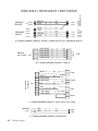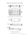
1
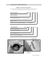
TRA INING GU ID E Splendide ® T E C H N I C A L E D U C AT I O N GROUP PRESENTS WD2100XC / XCP (Splendide 2100XC) WDC7100XCP (Splendide 7100XC) Front-Loading Automatic Washer-Dryer Training Guide Part No. TRAINMANXC Contact Info Product Specifications & Warranty Info Westland Sales, Splendide Tech Dept. 1-800-356-0766 EXT. 5 (503-655-2563) Technical Assistance & Parts Ordering Westland Sales, Splendide Tech Dept. 1-800-356-0766 EXT. 5 (503-655-2563) Literature Orders Westland Sales, Splendide Tech Dept. 1-800-356-0766 EXT. 5 (503-655-2563) Corporate Headquarters 15650 SE 102nd Ave. (PO BOX 427) Clackamas, OR 97015 Telephone: 800-356-0766 (503-655-2563) Service Fax: (503) 722-9202 Service E-mail: [email protected] w w w.splendide.com/suppor t.htm Introduction Westland Sales assumes no responsibility for repairs on Splendide products by anyone other than Authorized Splendide Service Technicians. Warranty repairs must be pre-approved by Splendide. Contact Westland Sales, before servicing any Splendide appliance. This Training Guide for the “Splendide Front-Loading Automatic Washer-Dryer,” (Part No. TRAINMANXC), provides the service technician with information on the installation and service of Splendide washerdryer models WD2100XC and WDC7100XC. It is to be used as a supplemental training aid for service technicians. For more information on the washer-dryer, refer to the “Use and Care Guide” provided with the appliance. Training Guide Goals The goal of this Training Guide is to provide information that will enable the service technician to properly diagnose malfunctions and repair the Splendide Front-Loading Automatic Washer-Dryer. The objectives of this Training Guide are for the service technician to: • understand and follow proper safety precautions, • effectively troubleshoot and diagnose malfunctions, • successfully perform necessary repairs, and • help the technician to quickly return the washer-dryer to its proper operational status Splendide ® © Copyright 2004, Westland Sales, Clackamas, OR 97015 i ii Contents 1. General Information 1 Model / Serial Number Designators Warranty Guide Washer-Dryer Specifications IMPORTANT General Safety Information 2. Installation Information 5 Installation Requirements Installation Instructions 3. Theory of Operation 1 2 3 4 5 9 13 Introduction to the Models Water System Wash/Dry System Door Lock / Switch Assembly Suspension System Customer Interface / Cycle Selection System Automatic Routines 4. Accessing the Components 13 13 15 17 17 18 24 27 Component Locations Top Panel / Control Panel Knobs Control Panel Board / Control Panel Door / Door Switch / Porthole Diaphragm Detergent Dispenser Assembly / Water Valves Pressure Switch Fan Motor / NTC Sensor / Heater Coil Removing the Heater Coil Lower Panel / Drain Pump / Pump Filter To Clean Out the Large Item Filter Back Panel / Main Motor / Module Board Shock Absorbers 27 28 29 30 31 32 33 34 35 36 37 38 (Continued on the next page) iii 5. Component Testing Procedures 39 Connector Locations on the Module Board Introduction / Instructions 1. Door Switch Test 2. Power “in” from the Surge Protector Test 3. Pressure Switch Test 4. Heating Element Test 5. Main Motor Test (Includes Running the Main Motor with AC Voltage) 6. Fan Motor / Water Pump Test 7. Water Valve / Wash NTC Test 8. Control Panel Board Test 9. Dry NTC Sensor Test 6. Diagnosis & Troubleshooting 50 Introduction Explanation of Fault Codes Fault Code / Testing Procedure Chart Problem / Testing Procedure Chart 7. Tech Tips 50 51 52 54 56 Manually Unlocking the Door Performing a Dryer Airflow & Heat Test Winterization Instructions / Optional RV Winterization Verifying Normal Operation 8. Wiring Diagrams 39 40 41 42 43 44 45 46 47 48 49 59-61 iv 56 56 57 58 General Information Model / Serial No. Designators Use these numbers to obtain the Warranty status as well as a history of repairs and service calls for the washer-dryer. To speed the repair process, ALWAYS have the Model and Serial No. ready when you call Westland Sales. Model Number WD C 7100XC p PRODUCT GROUP WD = Washer-Dryer PRODUCT IDENTIFICATION C = Condenser Drying System (Ventless model) PRODUCT CODE PRODUCT COLOR Arctic White if not noted (P = Platinum) Serial Number 7 S/N 07 14 3277 YEAR OF MANUFACTURE MONTH OF MANUFACTURE DAY OF MANUFACTURE PRODUCT SEQUENCE NUMBER Model Number Serial Number General Information 1 Warranty Guide* Refer to this page for a brief summary of the Product Warranties available by Splendide. Wty Length Splendide Will Pay For Splendide WILL NOT Pay For MFR 1-YEAR Replacement parts ONLY. A. Repairs when the washer-dryer is used in other than normal, single-family use. From Date of Purchase B. Pickup and delivery. The washer-dryer is designed to be repaired on-site. C. Removal/replacement of washer-dryer from built-in or cabinet installations. LIMITED 1-YEAR** For 1 year from the date of purchase WHEN product From Date of is registered. Limited replacement parts and repair Purchase D. Damage to the washer-dryer caused by labor costs. accident, alterations, misuse, abuse, fire, flood, (Not available for some models) acts of God, or use of products not approved by Splendide. LIMITED 2-YEAR** From Date of Purchase For two years from the date of purchase WHEN extended Protection Plan is purchased. Limited replacement parts and repair labor costs. (Not available for some models) LIMITED 5-YEAR ** From Date of Purchase E. Repairs to parts or systems resulting from unauthorized modifications made to the washer-dryer. F. Replacement parts or repair labor costs not pre-approved by Splendide and/or provided by an unauthorized service company. For five years from the date of purchase WHEN extended Protection Plan is purchased. G. Service calls to correct the installation of the washer or to instruct you how to use it. H. Plastic parts and cosmetic pieces.* (Not available for some models) *IMPORTANT! This chart should be used ONLY as a guide and DOES NOT supersede the Warranty Statement. For complete information, refer to the Warranty Statement that came with the appliance. ** Coverage starts 60 days after warranty registration or warranty registration with full payment is received by Westland Sales. 2 General Information Washer-Dryer Specifications The following is a list of product specifications for the Splendide Models covered in this Training Guide. Model Number COLOR DRYER TYPE ELECTRICAL REQ. Max. Current Rated Current Voltage Frequency Heating Power GALLONS WATER PER ‘Regular Cotton Heavy Duty’ cycle* MAX. LOAD CAPACITY Wash Dry MAX. SPIN SPEED Height Width Depth WEIGHT PROGRAMS Wash Dry WASH TEMP OPTIONS SPECIAL WASH OPTIONS WD2100XC / WD2100XCP WDC7100XCP White Vented Platinum Ventless 11A 15 A 120V 60Hz 1300W 7.5 Gal. 11A 15 A 120V 60Hz 1300W 7.5 Gal. 15 lb. 11 lb. 1200 RPM 33 1/4” 23 1/2” 22 3/16” 148 lb. 15 lb. 11 lb. 1200 RPM 33 1/4” 23 1/2” 22 3/16” 148 lb. 9 Cycles 3 Cycles 7 4 buttons 9 Cycles 3 Cycles 7 4 buttons *Avg. wash water use is 7.5-16 gal/wash load. Water usage varies depending on load size and fabric type. NOTE: WDC7100XC has a condenser (ventless) drying system. This condenser drying system uses 2.5 gallons of cold water per hour during the dry cycle. General Information 3 IMPORTANT General Safety Information Your safety is important. Read this section before you continue. Important safety messages can be found in this manual and on the appliance. Always read and obey all safety messages. ! This is a safety alert symbol. This symbol alerts you to potential hazards that can kill or hurt you and others. All safety messages will follow the safety alert symbol and the word “WARNING.” ! WARNING ELECTRICAL SHOCK HAZARD Plug washer-dryer into a grounded 3 prong outlet. Do not remove ground prong. Do not use adapter. The safety messages will tell you what the potential hazard is, tell you how to reduce the chance of injury, and tell you what can happen if the instructions are not followed. Do not use an extension cord. Failure to follow these instructions can result in death, fire, or electrical shock. ! WARNING ELECTRICAL SHOCK HAZARD Disconnect power before servicing. Replace all panels before operating. Failure to do so can result in death or electrical shock. ! WARNING EXCESSIVE WEIGHT HAZARD Use two or more people to move and install the washer-dryer. Failure to do so can result in back or other injury 4 General Information Electrostatic Discharge (ESD) Sensitive Electronics ESD problems are present everywhere. ESD may damage or weaken the electronic control assembly. The new control assembly may appear to work well after repair is finished, but failure may occur at a later date due to ESD stress. • Use an antistatic wrist strap. Connect the wrist strap to a green ground connection point or unpainted metal in the appliance; or touch your finger repeatedly to a green ground connection point or unpainted metal in the appliance. • Avoid touching electronic parts or terminal contacts. Handle the Module Board by the plastic housing ONLY. Installation Information Installation Requirements Check these location, plumbing and electrical installation requirements for a proper washer-dryer installation. Electrical • • • Machine Voltage/Amperage - 120V, 60 Hz, 1300 W, 10.5 Amp. Connection - 3-prong plug with 6’ cord is provided with the machine. Circuit/Protector - 3-wire single phase, 120V, 60 Hz, AC, on a separate 15 Amp circuit. Location • This machine may be installed free standing as well as in a recessed area, closet, or alcove • Minimum Installation Spacing - 0” on sides and 1” in front and back. NOTE: Additional installation spacing needs to be considered for easy installation, servicing, and compliance with state and federal codes. • Floor - Must support at least 280 lbs. and be a solid, level surface. DO NOT install on carpet. • RV/Marine Installations - When locating the appliance in a towable trailer or watercraft, position the machine over the axles or mid-ship where movement is at a minimum. Block the machine to prevent extreme movement. • Exhaust Requirements (WD2100XC Model ONLY) - Rigid or flexible metallic duct required. Ducting should be as short and straight as possible. DO NOT exhaust dryer into a chimney, furnace, cold air duct, attic crawl space, or another duct used for venting. If a cabinet door is installed, a minimum of 8 sq. in. should be provided for make up air. Louvered doors with equivalent air openings are acceptable. Allow clearances behind door(s) to avoid rubbing between back of cabinet door(s) and front of unit control panel. Additional clearances for wall, door and floor moldings may be required. If you have... You’ll need... no access to Hot/ Cold water hookups Splendide Faucet Adapter Kit, or equivalent. to install a dryer vent and ducting in your RV or boat Splendide Vent Kit, or equivalent. concerns about the appliance shifting in your RV or boat Splendide SecureFit bracket kit, or equivalent. water damage concerns Splendide Drain-A-Way Pan, or equivalent. to make a 90” duct turn in less than 4.5” Splendide 90˚ offset elbow, or equivalent. Drainage • Standpipe Diameter/Capacity - Needs a 1 ¼” minimum diameter standpipe with a minimum carry-away capacity of 7 gallons per minute. • Top of Standpipe - Must be between 25” and 34” high from the bottom of the machine. • Outlet End of Drain Hose (provided with the unit) - Must be at least 20” above the bottom of the washer-dryer. An air break must be available at the standpipe to avoid siphoning. No more than 6” of the drain hose should be inserted into the drain pipe to prevent siphoning. Installation Information 5 Washer-Dryer Dimensions Undercounter Install Requirements The dimensions shown are for the minimum spacing allowed. IN CM IN CM 0 in. (0 cm) IN CM 33-1/4 in. (84.5 cm) 0 in. (0 cm) 23-1/2 in. (59.7 cm) 0 in. (0 cm) IN CM Recessed Area/Closet Install Requirements The dimensions shown are for the minimum spacing allowed. IN CM IN IN CM CM Additional spacing should be considered for: • Ease of installation and servicing. • Additional clearances might be required for wall, door and floor moldings. • If cabinet door is installed, a minimum of 8 sq. in. should be provided for make up air. Louvered doors with equivalent air openings are acceptable. 6 Installation Information Drain System Requirements Sink Drain W/ "Y" Branch Tailpiece The washer-dryer can be installed using the standpipe drain system, floor drain system or the sink drain system. To prevent siphoning, the outlet end of the drain hose MUST always be 20” (50.8 cm) above the base of the machine. Not more than 6” (15.24 cm) of the drain hose should be inserted into the drain pipe. Floor Standpipe Wall Standpipe Laundry Sink Drain 25" (62 cm) min. with an air break Cable tie "Y" Tail Piece B 20" (51.8 cm) min. 34" (86 cm) max. Standpipe A This connection MUST be before drain trap and at least 20" (50.8 cm) above the floor where washer will be installed. Fig. 7 Floor Standpipe w/ "Y" Branch Tail Piece A & B = 25" (62 cm) min. / 34" (86 cm) max. The standpipe drain requires a minimum diameter standpipe of 1-1/4” (3.2 cm). The minimum carry-away capacity can be no less than 7 gal (26.5 L) per minute. The top of the standpipe must be at least 25 in. (62 cm) high and no higher than 34” (86 cm) from the bottom of the washer. The floor drain system requires a siphon break that may be purchased separately. Optional • The Splendide Faucet Adapter Kit, Part No. 154187104A • Supplies water from the faucet and discharges water directly into the sink. • Designed for installations where washer-dryer hookups are not available. Faucet Adapter Kit, Part No. 154187104A (Continued on the next page) The sink drain system connected to a garbage disposer requires a “Y” connector (sold separately. U-Clamp 6" max. Standpipe 25" (62 cm) min. 34" (86 cm) max. 20" (50 cm) min. with an air break Installation Information 7 Electrical Requirements ! WARNING GROUNDING INSTRUCTIONS This appliance must be grounded. In the event of a malfunction, or breakdown, grounding will reduce the risk of electric shock by providing a path of least resistance for electric current. This appliance is equipped with a cord having an equipment grounding conductor and grounding plug. The plug must be plugged into an appropriate outlet that is properly installed and grounded in accordance with all local codes and ordinances. DO NOT modify the plug provided with the appliance. If it will not fit the outlet, have the proper outlet installed by a qualified electrician. WARNING: Improper connection of the equipmentgrounding conductor can result in a risk of electric shock. Check with a qualified electrician or serviceman if you are in doubt as to whether the appliance is properly grounded. 8 Installation Information ELECTRICAL SHOCK HAZARD Plug washer-dryer into a grounded 3 prong outlet. Do not remove ground prong. Do not use adapter. Do not use an extension cord. Failure to follow these instructions can result in death, fire, or electrical shock. • A 120-volt, 60-Hz., AC-only, 15 or 20-amp, fused electrical supply is required. Time-delay fuse or circuit breaker is recommended. It is recommended that a separate circuit serving only this appliance be provided. • This washer-dryer is equipped with a power supply cord having a 3-prong ground plug. • To minimize possible shock hazard, the cord must be plugged into a mating, 3-prong, ground-type outlet, grounded in accordance with local codes and ordinances. If a mating outlet is not available, it is the personal responsibility and obligation of the customer to have the properly grounded outlet installed by a qualified electrician. • If codes permit and a separate ground wire is used, it is recommended that a qualified electrician determine that the ground path is adequate. • Do not ground to a gas pipe. • Check with a qualified electrician if you are not sure the washer is properly grounded. • DO NOT use an extension cord. • Do not have a fuse in the neutral or ground circuit. • DO NOT install or store this appliance where it will be exposed to weather or in an area where gasoline or other flammables are stored. Installation Instructions Follow these instructions in order to prevent installation errors and to assure proper washer-dryer operation. Unpacking the washer-dryer • • Carefully remove the packing materials with care not to damage the drain hose and power cord that are shipped installed on the machine. Check that the machine is intact. Report any damage immediately. Position the washer-dryer near the desired installation position. Connecting the water inlets If the water pipes you will be connecting to are new or unused, run the water until clear to remove any debris that could clog the water valve screens or valves before connecting the machine. NOTE: Supply shut-off valves should be easily accessible. IMPORTANT: Water pressure MUST range within the values indicated on the “Technical Data” chart WARNING: Plastic bags, styrofoam, nails and other packaging parts are not children’s toys and can be potentially dangerous. Destroy the carton and plastic bags after the • washer-dryer has been unpacked. Removing the transit screws • For transportation, the inside of the machine is supported by screws, rubber grommets and spacers on the back panel. Before using the washer-dryer, these items MUST be removed. IMPORTANT: Transit screws and spacers must be removed before operating the machine to allow proper operation of the machine and to prevent damage to the appliance. • • After positioning the washer-dryer near the installation location, remove the four screws (Fig.1), with the rubber grommets and plastic spacers that are attached to them. Use the plastic plugs (provided in the accessories bag) to fill in the holes. • Included in the accessories supplied with your machine are 2 inlet hoses with 4 rubber washers pre installed. Check that the rubber washers are installed in the ends of the inlet hoses to make a water tight seal at each connection point. Connect the straight ends of the water inlet hoses to the supply taps that have ¾” BSP thread (standard hose bib). Connect the 90º angled ends (20 mm thread) of these hoses to the inlet valves on the back of the machine (Fig. 2). NOTE: Water Inlet valves are color coded: Red (Hot) & White (Cold). IMPORTANT: Do not use excessive force. Damage to the couplings can result. The couplings should be tightened by hand; a tool should only be used if a leak occurs. IMPORTANT: Retain the transit screws, spacers and rubber tubes. These items should be reinstalled to prevent damage if or when you transport the machine in the future. Installation Information 9 Connecting the drain hose It is possible for the water to be discharged into a sink, standpipe or drainpipe, but an air break must be available at a minimum 20” height to prevent the machine from siphoning (Fig. 6). the floor to a separate trap. The trap must be vented to prevent siphoning. To provide proper venting, install an Air Gap Kit (available at most hardware stores). 4) To the faucet using a Faucet Adapter Kit (available separately). IMPORTANT: Make sure that the drain hose is not kinked and that water flow is not restricted. • • Standpipe Drain System - Installations require a minimum 1 ¼” (3.2 cm) diameter standpipe with a minimum carry away capacity of 7 gallons (26 liters) per minute. Wall or Floor Standpipe Drain System - The top of the standpipe must be between 25” (62 cm) - 34” (86 cm) from the bottom of the washer (Fig. 4). Sink Drainpipe System - Entry into the sink drain system must be above the trap (Fig. 5). When routing the drain hose through cabinets or walls, use a protective material such as electrical or duct tape to cover sharp edges that could damage the drain hose. Use a suitable clamp to secure the drain hose to the “Y” branch or the disposer (Fig. 7). With a sink drainpipe system, you may connect directly: 1) to a disposer by following the manufacturers attachment method. 2) directly to a “Y” branch tail piece (available at most hardware stores). 3) Through 10 Installation Information • Use a U-Clamp (provided in your accessories packet) or suitable item to secure the outlet end of the drain hose (pre-installed on the back of your machine). Insert the outlet end of the drain hose into the standpipe, wall or floor drain (Fig. 6). NOTE: The outlet end of the drain hose MUST be at least 20” (50 cm) above the base of the machine. No more than 6” of the drain hose should be inserted into the drain pipe to prevent siphoning. Use a strap, cable tie, or similar item to hold the hose or the U-Clamp in place. Installing the exhaust ducting (WD2100XC Model ONLY) IMPORTANT: This Leveling the washer-dryer (All Models) • appliance should NOT be exhausted into a chimney, wall, ceiling, or any concealed space of a building. Only rigid or flexible metallic ducting should be • used. • • • • • Rigid or flex metal/metallic ducting should be used. Exhaust ducts should be as short and straight as possible. NOTE: Long exhaust ducting can extend drying time, collect lint and may affect drying performance. The exhaust duct must end with an approved exhaust vent hood with swing out damper(s) or tailpiece with louvers. Check that all ducting is clean and lint free. Use duct tape or screw clamps to secure all joints. Use duct tape or screw clamps to secure the duct to the round flange vent located on the back of the machine (Fig. 8). • To access the front leveling legs, tilt the machine backwards, leaning it against a wall or other stable structure. Adjust the legs up or down (Fig. 9) to ensure the washer is resting solid and does not rock side-to-side or front-to-back when the machine is upright. Check that the angle of inclination, measured according to the work top, does not exceed 2°. IMPORTANT: The machine must rest solid on a sturdy floor for optimum performance and minimum vibration. WD2100XC WARNING! -To reduce the risk of fire, this appliance must be exhausted to the outdoors. Rigid or flexible metallic duct required. Ducting must be as short and straight as possible. Do not exhaust dryer into a chimney, furnace, cold air duct, attic crawl space, or another duct used for venting. If a cabinet door is installed, a min. opening of 8 sq. in. should be provided for make up air. Louvered doors with equivalent air openings are acceptable. Allow clearances behind door(s) to avoid rubbing between back of cabinet door(s) and front control panel. Additional clearances for all, door and floor molding may be required. Installation Information 11 Completing the installation • • • • • • • • Check the electrical requirements. Be sure that you have the correct electrical supply and the recommended grounding method. Check that the shipping brackets have been removed. Check that the water faucets are ON. Check for leaks around faucets and inlet hoses. Plug washer into a grounded 3-prong outlet. Slide the washer-dryer to it’s final location and confirm that it’s level. When installing this appliance in an RV or marine vessel, you should block in the unit to prevent it from shifting or tipping. A SecureFit Bracket Kit is available from Splendide to keep the unit from shifting front-to-back or side-toside. Test and clean the washer. Run a test load with no laundry. Testing and cleaning the washer, • Press the ON-OFF button to turn the washer ON • Pour 1 to 2 TBSP of powder detergent into the detergent dispenser compartment ‘2’ • Select wash program ‘2’. • Make sure the DRY TIME knob is in the ‘OFF’ position. • Then press START. Allow the washer to complete the wash cycle. 12 Theory of Operation Introduction The Splendide Front-Loading Washer-Dryer models present many new features and characteristics that are different from previous models. In addition to the introduction of electronic controls, the washerdryer contains a number of unique operating features designed to offer extremely high water and energy conservation while increasing fabric cleaning results. Water System The water system consists of the hot and cold water inlet valves and the dispenser distribution system along with a traditional pressure switch. Water Inlet Valves The hot and cold water inlet valves are located at the back, top-left of the washer. These valves receive a control signal from the Module Board to manage the temperature of incoming water. The temperatures are determined by the specific wash temperature selected. (See chart on next page) Dispenser Distribution System All wash and rinse water is introduced into the drum through a Dispenser Distribution System that diverts the incoming water to one or more of the follow water inlet modes: Detergent Dispensing, Bleach Dispensing, Fabric Softener Dispensing. The dispenser drawer has three separate compartments (plus one removable bin) for adding laundry products to the wash load. These compartments are: 1. Prewash Detergent (w/removable Bleach Bin) 2. Main Wash Detergent 3. Fabric Softener Compartment All of the water flows through the dispenser assembly. Laundry products are diluted and dispensed automatically at the proper time during the wash cycle. Refer to “Use and Care Guide” that came with the appliance for proper use of laundry aids. Theory of Operation 13 Pressure Switch The pressure switch is located in the top, right-front corner of the washer. This switch senses the water level in the drum. The control signal from the pressure switch is sent to the Module Board and is used to determine the amount of water introduced into the drum during the wash cycle. Pressure Switch WASH TEMP Knob Position Wash Temp.* HOT (Red) 140°F / 60° C 131°F / 55° C 122°F / 50° C 104°F / 40° C 95°F / 35° C 86°F / 30° C FROM COLD VALVE ONLY FROM COLD VALVE ONLY WARM (Grey) COLD (Blue) 1:30 3 o’clock 4:30 6 o’clock 7:30 9 o’clock 10:30 12 o’clock *NOTE: Actual wash water temperatures may vary depending on the temperature set at the water heater. Rinse temperatures are ALWAYS COLD. 14 Theory of Operation Wash/Dry System The Wash/Dry System consists of the Module Board, the Main Motor, the Pump Motor and the Dryer Heating Element. Module Board The Module Board is located at the bottom, right-rear corner of the washer-dryer. If diagnostic tests indicate that the module board is defective, the entire module board must be replaced. The module board receives input from the Control Panel/LED assembly and directly controls the dispenser, drain pump, water inlet valves, door locking and unlocking, fan motor and heating element relay. The module board monitors the pressure switch, and door lock switches. Main Motor The main motor is located at the bottom, rear of the washer and is an infinite speed, 3 phase brushless motor that operates at various speeds and directions based on input voltages from the module board. (Continued on the next page) Theory of Operation 15 Pump Motor A separate pump/pump motor is used to drain the drum (Fig. 3-1).The pump motor is 120 VAC and is attached directly to the pump. The pump has a filter located at the bottom-front that allows for the removal of large objects like keys and coins that may have passed from the basket. (Fig. 3-2) Large Object Filter Drain Pump Dryer Heating Element The Dryer Heating Element is located in the heater duct assembly on the top-right of the drum. The Module Board provides power to the element in the dry cycle. During the dry cycle: • Vented model (WD2100XC) take air from the surrounding room, heat it, tumble it through the clothes, and then exhaust it to the outside through a vent. • Ventless model (WDC7100XC) require 2.5 gallons of cold water per hour during the dry cycle. (See below.) Dryer Heating Element How Does Ventless Drying Work? 1. As damp laundry tumbles, the inner drum is heated. Heat draws the moisture out of the laundry in the form of STEAM. 2. Cold water cools the OUTER TUB. The cold surface attracts the warm, saturated air. STEAM passes through the holes in the INNER DRUM to reach the OUTER TUB. 3. When the STEAM hits the cooled surface of the OUTER TUB, it’s condensed back into water. The water is then pumped out the drain. Process repeats until clothes are dry. NOTE: Do not attempt to dry less than 2.2 lbs of laundry during the Cotton Heavy Duty Dry cycle. 16 Theory of Operation Door Lock/Switch Assembly The Door Lock/Switch Assembly is located on the right side of the door opening. The assembly contains a solinoid operated latching mechanism that will electrically lock the door during a wash or dry cycle. Door Lock/Switch Assembly Suspension System The drum assembly is held in position with two shock absorbers attached to the bottom sides of the tub assembly. In addition, the drum is suspended from the top frame of the washer with three springs attached to the sides of the case. Stability for this suspension system is provided by two concrete counter weights. One is located at the top and one at the bottom-front of the outer drum. Springs Top Counter Weight Bottom/Front Counter Weight Shock Absorbers Theory of Operation 17 Customer Interface / Cycle Selection System The Customer Interface / Cycle Selection System consists of the Control Panel/LED Assembly along with the program timer, option buttons, and Wash Temperature and Dry Time Selectors. Control Panel/LED Assembly The Control Panel/LED Assembly (Fig. 3-3) is removed as a single assembly and is connected to the Module Board by 5 connection points to the wiring harness. The assembly contains all the buttons, LED’s and switches for the user to operate the washer-dryer. This interfaces what the consumer commands to the Module Board. 18 Theory of Operation Description of Control Panel Buttons, Knobs & LED’s ON/OFF Button- Use the ON/OFF Button to turn machine power ON or OFF START Button- Use this button to START a cycle (press once) or RESET the controls (press and hold for 5 seconds). For more information, see “Resetting the Controls” on page 20. Option Buttons START/RESET Button Door Lock LED ON/OFF Button Cycle Status LED’s Dry Time Selector Wash Temp. Selector Cycle Selector Option Buttons - Use these buttons to modify the wash cycle (see “Description of Option Buttons”) Door Lock Light - This light indicates when the door is locked (LIT SOLID) and when it can be safely opened (BLINKING). Water Temperature Selector - Choose a water temperature by turning the knob to the desired selection. Refer to the garment label and choose the warmest water safe for the fabric. Choose a slightly lower temperature to get the same wash results while saving energy. NOTE: Rinse is always COLD. Dry Time Selector - Choose a dry time by turning the knob to the desired selection. Choose OFF up to MAX LOAD (180 minutes). ‘Very Dry’ and ‘Less Dry’ auto dry cycles are available on the WDC7100XC model ONLY. This DRY TIME knob does not move during the dry cycle. Cycle Selector - Choose a wash cycle or dry cycle by turning the knob to the desired cycle. Each cycle is designed for different types of fabric and soil levels. Theory of Operation 19 Resetting the Controls Clearing the controls - Pushing and HOLDING the START button for 5 seconds will cancel the current program and allow you to set a new one. Cancelling a cycle in progress and setting a new cycle - Use the START button to cancel a program in progress and start a new cycle: 1. press and HOLD the START button for 5 seconds, 2. select a new cycle, then 3. press the START button and the new cycle will begin. Description of Cyle Selector Options Rinse - Use a Rinse cycle to get a rinse and spin only. A Rinse is useful for loads that need rinsing only or for adding fabric softener to a load Spin - Use the Spin cycle to spin a wet load of laundry at 1200rpm Drain - Use the Drain cycle to drain the washer-dryer Description of Option Buttons You can customize the wash by adding an OPTION or combination of options to your cycle selection. You can add or change the options after starting a cycle anytime before the option begins. (See “Preset Wash/Dry Cycles Chart”) Extra Rinse - Pressing this button will add an extra rinse cycle Low Spin - Pressing this button will reduce the spin speed to 600 rpm Low Heat - Pressing this button will reduce the heat temperature during dry Pre-Wash - Pressing this button will add an extra fill at the beginning of the cycle 20 Theory of Operation Description of Preset Wash Cycles Cotton Heavy Duty Wash - Use the Cotton Heavy Duty cycles to wash loads of sturdy, colorfast fabrics and normally to heavily soiled garments. These cycles combine fast speed tumbling and an extra high spin speed (1200 RPM) to shorten dry times. • • • • SUPER - Use this cycle to wash exceptionally soiled cotton garments. HEAVY - Use this cycle to wash heavily soiled garments. REGULAR - Use this cycle to wash normally soiled garments. EXPRESS - Use this cycle to wash smaller loads of lightly soiled garments in less time. Permanent Press Wash - Use the Permanent Press cycles to wash loads of no-iron fabrics such as sport shirts, blouses, casual business clothes, permanent press blends, linens, and other synthetic fabrics. These cycles combine medium speed tumbling and a high-speed spin (1000 RPM) for reduced wrinkling of synthetic fabrics. • • • • HEAVY - Use this cycle to wash heavily soiled synthetic fabric garments. REGULAR - Use this cycle to wash normally to heavily soiled garments. GENTLE - Use this cycle to wash lightly soiled garments. EXPRESS - Use this cycle to wash smaller loads of lightly soiled garments in less time. Delicates Wash - Use the Delicates Cycles to wash sheer fabrics, silk, wool, lingerie and other hand washable items. These cycles combine variable speed tumbling and a low spin speed (800 RPM for WOOL) or Drain ONLY (SILK) for gentle fabric care. (Check the label instructions to make sure that the garment is washable.) • SILK - Use this cycle to wash silk items, lingerie, and other particularly delicate fabrics. • WOOL - Use this cycle to clean washable woolen garments and other hand washables. How to Set a ‘Wash ONLY’ Cycle: 1. Press the ON/OFF Button to turn the machine power ON (If necessary, press and HOLD the START button to clear the previous cycle) 2. Use the Cycle Selector to select a wash cycle 3. Set the Dry Time knob in the ‘OFF’ position 4. Press the START Button. The wash cycle will begin. Theory of Operation 21 Description of Preset Dry Cycles Cotton Dry - Use this high heat cycle to dry sturdy, colorfast fabrics like towels socks and jeans. There’s a high spin at the beginning of this cycle to remove more water from fabrics. Synthetics Dry - Use this medium heat cycle to dry certain blouses and casual business clothes. Wool Dry - Use this high heat dry cycle to dry wool items ONLY. Cotton Heavy Duty Dry Wool Dry Synthetics Dry How to Set a ‘Wash-to-Dry’ cycle 1. Press the ON/OFF Button to turn the machine power ON (If necessary, press and HOLD the START button to clear the previous cycle) 2. Use the Cycle Selector to select a wash cycle 3. Use the Dry Time knob to select the duration of the dry cycle 4. Press the START Button. When the wash cycle is finished, the appropriate dry cycle will begin automatically How to Set a ‘Dry ONLY’ cycle 1. Press the ON/OFF Button to turn the machine power ON (If necessary, press and HOLD the START button to clear the previous cycle) 2. Select a Dry Cycle using the Cycle Selector (13, 10, or 5) 3. Use the Dry Time knob to select the duration of the dry cycle 4. Press the START Button. The dry cycle will begin 22 Theory of Operation Preset Wash/Dry Cycles Chart*** Program Knob Type of fabric Degree of soil Cycle Name No. Detergent Pre Wash * Wash Fabric Softener Bleach • • • • • Special Programs Cycle Length Low Heat Extra Rinse Low Spin 96 min. Cycle Description Cotton Heavy Duty Cycles Heavy cotton fabrics: i.e. sheets, socks, towels, jeans, underwear, sweatshirts, etc. Exceptionally Soiled 1 Super Heavily Soiled 2 Heavy • Soiled 3 Regular • • • Lightly Soiled 4 Express • • • - 5 Dry 6 Heavy NOTE: A spin cycle is carried out at the beginning of this dry cycle Low Heat Pre Wash Extra Rinse Low Spin 77 min. Low Heat Low Spin 20 to 180 min. Low Heat Pre Wash Extra Rinse 66 min. 77 min. Wash cycle, rinse cycles, intermediate and final spin cycles. (1200 RPM High Spin) 63 min. Spin cycle, timed drying (High Heat) Permanent Press Cycles Heavily Soiled Synthetic, light cotton and more delicate fabrics: i.e. button-ups, khakis, rayon shirts, etc. • • • Soiled 7 Regular • • • Lightly Soiled 8 Light • • • Lightly Soiled 9 Express • • - 10 Dry 11 Silk Low Heat Pre Wash Extra Rinse Low Spin 59 min. 53 min. Wash cycle, rinse cycles, intermediate and final spin cycles. (1000 RPM High Spin) Low Heat Low Spin 33 min. Low Heat 20 o 180 min. Timed drying (Medium Heat) • Low Heat Pre Wash Extra Rinse 30 min. Wash cycle, rinse cycles, anticrease or Drain ONLY. (NO Spin) • Low Heat Extra Rinse Low Spin 65 min. Wash cycle, rinse cycles, anticrease or spin cycles. (800 RPM High Spin) To prevent wrinkles, cycles 11 and 12 will end with the laundry left to soak and the ‘Rinse’ LED flashing. To finish the cycle, press the START button Low Heat 20 to 180 min. Timed drying (High Heat) Rinse NOTE: When used, fabric softener is automatically dispensed during the last rinse of each cycle. Low Heat Extra Rinse 35 min. Rinse cycles, intermediate and final spin cycles Spin NOTE: High spin speed varies depending on the cycle you choose. Low Spin 16 min. Draining and final spin cycle Drain Drains any water from the drum - 1 to 4 min. Drain ONLY. NO spin cycle. - Delicates Cycles** Silk and particularly delicate fabrics Wool and Hand Wash fabrics Delicate and lighter fabrics prone to wrinkling Soiled Soiled 12 Wool - 13 Dry** • • • • • About Rinse, Spin and Drain * Above cycle lengths may vary according to water pressure, load size and fabric type. ** Silk cycle cannot be set to go from ‘wash-to-dry’ automatically. NOTE: Some options cannot be added to some cycles. ***Above cycle times will vary according to water pressure, load size and fabric type. Theory of Operation 23 Automatic Routines The following are routines that the washer-dryer will follow out automatically during all of the wash, spin, rinse and dry cycles. Door Locking / Unlocking Routines Door Locking Summary - The Door Locking Routine will only start if the door is securely closed and the Door Switch contact is CLOSED. 1. The Door Switch is energized whenever a cycle is started. 2. During the next few seconds, the contacts on the door switch are checked by the Module Board. The Status/Door Lock light will go SOLID and the cycle will begin. Door Unlocking Summary - Unlocking will occur ONLY under these conditions: 1. The Main Motor speed equals “0” 2. The water level in the drum does not exceed the door seal 3. The cycle is finished 4. The cycle has been interrupted by following the ‘Add-An-Item’ instructions below ‘Add-An-Item’ CHILD DOOR LOCK NOTE: The ‘Add-An-Item’ feature is not available whenever it is unsafe to open the door (i.e. during high spins, if water level is to high, etc.) 24 Theory of Operation • Press the ON/OFF button; Resume Unlock This washer-dryer is equipped with a Child Door Lock. For your child’s safety, the door stays locked for the duration of the WASH and DRY cycles. However, the ‘Add-An-Item’ feature allows you to unlock the door when needed. You will hear 2 ‘clicks’ when the door unlocks. It is now safe to open the door. • Close the door; • press the ON/OFF button to resume the cycle. IMPORTANT: Never attempt to open the door when the Door Lock LED (D) is LIT SOLID. Wash Quality Routines Drain and Spin Routines - During the Drain and Spin cycles, the water level is checked continuously. Normal Drain and Spin will occur until the Pressure Switch senses no water or foam (suds) in the drum. Foam Detection and Elimination Routine - Excessive foam can make clothes appear dingy and is usually caused by the use of too much detergent, or the wrong kind of detergent. If the Pressure Switch senses the presence of foam during the Drain or Spin Routine, the Module Board will stop the main motor and the basket will stop spinning. The Drain Pump will turn OFF and the drum will fill with water. Once the tub is filled, the basket will rest for several minutes in an attempt to eliminate the foam before resuming the original cycle. This process will repeat until no foam is detected. Impulse Spin Technology (IST) - During the Spin cycle the drum will rotate at varying speeds before reaching high spin (instead of a constant pace). This routine optimizes rinse efficiency and drying uniformity - clothing comes out with less creasing and wrinkling. Automatic Balance Routine Automatic Balance Routine Summary - An unbalanced load can cause excessive noise and vibration. The Automatic Balance Routine occurs during the distribution ramp (while the basket spin is accelerating from 40 to 600 rpm). At 600 rpm the motor is decelerated and the rate of deceleration is monitored by the Module Board. The motor is then ramped up to 600 rpm and shut off. The rate of deceleration is monitored again and compared to the first deceleration rate. Based on this comparison, the Module Board can determine whether an unbalanced condition exists or not. • If the Module Board does not sense an unbalanced condition, the ramp will continue. • If the Module Board senses an unbalance condition, the Main Motor will rotate slowly back and forth for the remainder of the cycle. Theory of Operation 25 NOTES: 26 Accessing the Components Component Locations Follow the instructions in this section to gain access the following components. *#4",/#+ $29%26%.4(/3% 7$8# &!.-/4/2 #/5.4%2 7%)'(4 (%!4%2#/), !.$(/53).' (DRY NTC) $%4%2'%.4 $)30%.3%2 02%3352% 37)4#( $25- #/.42/, 0!.%, "/!2$ #/.42/, 0!.%, (/4 7!4%2 6!,6% #/,$ 7!4%2 6!,6% 0/7%2 #/2$ $//2 37)4#( $29%2 6%.4 7$XC 3(/#+3 0/24(/,% $)!0(2!'- $2)6% "%,4 $2!).05-0 !33%-",9 -/$5,% "/!2$ $2!).(/3% -!).-/4/2 Accessing the Components 27 Required Tools To access components in this washer-dryer, you’ll need Metric and Standard sockets of various sizes, Torx-15, 25 Drivers, a Flat Head screwdriver, and a Phillips Head screwdriver. Top Panel / Control Panel Components Access to the Control Panel requires that the top of the washer be removed. Removing the Washer-Dryer Top Removing the Knobs Two Phillips Head screws secure the main top at the back of the washer-dryer (Fig. 4-1). Remove these screws and lift straight up on the rear of the main top. Remove the knob by pulling straight out. If you need to use pliers, make sure to use a shop rag as a buffer, so the knob does not get damaged. 28 Accessing the Components Removing the Control Panel Board Removing the Control Panel 1. Remove the wire connector from the panel board (Fig. 4-2). 2. Remove the two Phillips screws that secure the panel board to the control panel (Fig. 4-2). 3. Gently lift up on tabs on the back of the control panel board (Fig. 4-2) and push in the tabs on the selector knob shafts (Fig. 4-3) and pull out panel board using care not to break the tabs. 1. Remove the three Phillips Head Screws (Fig. 4-4) located behind the Dispenser Drawer 2. Remove the two Philips Head Screws located on the top corners of the Control Panel (Fig. 4-5) and then lift the entire panel straight off. Wire Harness Connector TABS SCREWS SCREWS TABS Fig. 4-4 Fig. 4-2 Cycle Selector Knob Tabs TABS SCREWS Fig. 4-5 Fig. 4-3 Accessing the Components 29 Door / Door Switch / Porthole Diaphragm Open the Door to access the Door, Door Switch and Porthole Diaphragm. Removing the Door panel. (See “Removing the Porthole Diaphragm” to remove the entire diaphragm.) The door switch is secured to the washer front panel with two, size 15 Torx screws. (Fig. 4-9) Once these screws are removed, the door switch will remain in place until it is lifted slightly and pulled back from the washer panel. Then, remove the wire plug from the door switch. Remove the two, size 15 Torx screws that secure the door to the door hinge. (Fig. 4-6) SCREWS Door Switch Removing the Door Switch If the top cannot be removed, access to the door switch requires that the porthole diaphragm be eased back from the front of the washer. To do this, locate the retainer spring and use a small tool to grab the hoop in the spring. (Fig. 4-7) Pull the retainer forward and then off the perimeter of the diaphragm. Removing the Porthole Diaphragm The porthole diaphragm can be completely removed from the outer rim of the tub assembly. Locate and remove the large sprig that holds the porthole to the drum (Fig. 4-10). Pull the diaphragm off the drum and out of the machine. Note: The Heater Housing and Coil enter the boot at the 1 o’clock position. Use care not to damage the diaphragm. Ease the edge of the diaphragm off of the lip of the washer front near the door switch. (Fig. 4-8) Remove enough of the diaphragm to gain access to the door switch behind the washer dryer front Fig. 4-10 30 Accessing the Components Detergent Dispenser Assembly / Water Valves Access to the Detergent Dispenser and Water Valves requires that the top of the washer be removed. Loop Removing the Dispenser Assembly Begin by removing the top, then use two hands to pull the dispenser drawer completely out of the housing. (Below) Disconnect the dispenser hose from the detergent dispenser assembly by pulling the loop on the hose off to the side of the assembly. (Fig. 4-13) Once that is removed, the hose can be pulled straight off. Now you can lift the detergent dispenser assembly out. IMPORTANT! Remove the three Phillips Head screws securing the front of the detergent dispenser assembly to the front of the Control Panel. (Fig. 4-11) Remove the two screws securing the detergent dispenser assembly to the dispenser valves. (Fig. 4-12) Disconnect the two wires from the hot valve. Be sure to reattach the hose correctly, or it will vibrate off of the bottom of the housing and the unit will leak water. Removing the Water Valves SCREWS When the Detergent Dispenser Assembly is removed, the water valves will be exposed. Make sure the water valve seals are correctly installed on the water valves before re-assembly. (Fig. 4-14) Remove the two screws that secure the valves to the back of the machine. (Fig. 4-15, next page) Accessing the Components 31 IMPORTANT! It’s very important to note the orientation of the wiring on the valves for re-installation. If the wiring is switched the water temperatures will be incorrect, and on condenser machines, the dry cycle will not operate correctly. Pressure Switch The Pressure Switch is located on the top-right, front corner of the machine. The pressure switch can be accessed once the top is removed. Removing the Pressure Switch Using pliers, squeeze the clamp to disconnect the black hose from the bottom of the pressure switch. (Fig. 4-16) Be careful not to pull up on the hose too much, or it may become disconnected from the bottom of the drum. Next, squeeze the tabs (Fig. 4-16) to remove the wiring harness connectors from the pressure switch. Be sure to check the wire connector for a tight connection after re-installation. Gently wiggle the switch back and forth while pulling out to remove the switch from the cabinet (Fig. 4-17). Fig. 4-17 32 Accessing the Components Fan Motor, NTC Sensor and Heater Coil The Fan Motor, NTC Sensor, Heater Coil and Housing sit on the drum and are located on the top, right side of the machine. It can be accessed once the top is removed. Removing the Fan Motor Disconnect the two wires that are attached to the fan motor and the ground wire attached to the housing (Fig. 4-18). Next, remove the seven, size 15 torx head screws that secure the two halves of the heater housing. Lift the top of the housing straight off and turn it over. Wires Remove the 10mm nut with LEFT-HANDED threads (Below) that secures the impeller to the motor shaft. Lift the impeller straight off the fan motor shaft. You may need to use a punch. NOTE: Make sure the impeller does not touch the gasket when re-installed. If the gasket is damaged it will need to be replaced. Nut Fig. 4-19 NTC Sensor Removing the NTC Sensor Lift the NTC Sensor from the heater housing (Fig. 4-18). Remove the Wire Harness Connector from the sensor. NOTE: When reinstalling the sensor, make sure the plastic housing is lined up with the duct assembly. Accessing the Components 33 Removing the Heater Coil Remove the two wires from the heater coil and lift the heater coil out of the heater housing. Fig. 4-20 Heater Coil 34 Accessing the Components Lower Panel / Drain Pump / Pump Filter The Drain Pump is located at the lower, right-corner of the machine. You’ll need to remove the Lower Panel to access the Drain Pump and Pump Filter. Removing the Lower Panel Removing the Drain Pump Gently ease down the top of the panel with a flat blade screwdriver or plastic putty knife. With the Lower Panel removed and any residual water drained from the unit, gently tip the washer onto its’ left side. Remove the panel by lifting slightly and pulling forward. (Below) Remove the 4 screws that secure the sheet metal cover to the bottom of the washer. (Below) Remove the metal cover. Remove the two screws that secure the pump to the cabinet. (Fig. 4-23) Rotate the pump clockwise from inside the unit and then pull to remove it from the cabinet. (Continued on the next page) Accessing the Components 35 Before you disconnect the hoses, note their orientation and place a towel under them to catch any water left inside. Unclamp the hoses from the drain pump and remove the pump assembly. (Fig. 4-24) To Clean Out the Large Item Filter To clean out the Large Item Filter, turn the large knob counterclockwise and pull it out. (Below) Place a small pan or towel under the pump prior to removing the large item filter. There WILL be water in the pump housing. 36 Accessing the Components Back Panel / Main Motor / Module Board The Main Motor and Module Board can be accessed once the back panel has been removed. Removing the Back Panel Removing the Module Board Remove the 7 Phillips screws that secure the panel to the back of the cabinet. (Below) Now lift the panel off. Remove the two, size 15 Torx Head screws that secure the Module Board to the case (below). Gently tip the unit on it’s left side (looking from the back). Next, take the wires out of the retainers on the Module Board Housing (Fig. 4-26). Note all wire connections, then remove the wire connectors from the module board and lift the board out of the unit. Removing the Main Motor After removing the back panel, remove the Drive Belt. Next, remove the two 13mm mounting bolts that secure the motor to the tub. (Fig. 4-25) Slide the motor out of the unit. Wire Retainers Bolts Fig. 4-26 IMPORTANT! When re-installing the Main Motor, it’s very important to make sure that it’s properly re-seated and aligned, with the hangers lined up with the back side of the motor. Accessing the Components 37 Shock Absorbers The Shock Absorbers can be accessed once the bottom panel has been removed. Removing the Bottom Panel Removing the Shock Absorbers The tub is held in position by two shock absorbers. To access the Shock Absorbers, First, place the washer-dryer on its left side. Remove the bolts that secure the shock absorbers to the tub using a 12mm, 15mm or 13mm socket (depending on serial number). Remove the 4 screws that secure the sheet metal cover to the bottom of the washer. (Below) Now, remove the metal cover. Remove the plastic plugs that secure the shock absorbers to the bottom of the case using needle nose pliers. (Fig. 4-27) Bolts Plastic Plugs Fig. 4-27 38 Accessing the Components Component Testing Procedures Connector Locations on the Module Board The following tests are performed by taking ohm readings on the Module Board connections listed below. The Module Board can be accessed once the back panel has been removed. See “Component Access Locations.” 1 2 3 4 1 2 3 4 5 6 7 8 9 5 6 7 8 9 COMPONENT Pressure Switch CONNECTOR J3 FAULT CODES* F04, F05, F07, F08, F10, F15 Heating Eement J2 F14, F15 Door Switch J4 F17 Power in from Surge Protector J1 N/A Main Motor and Waer Pump J9 F01, F02, F11 Dry NTC Sensor / Condenser Valve ** J10 F13, F14 Fan Motor J16 N/A Water Valves/Wash NTC J8 F03 Control Panel Board J11 F12 * For more information about how to read Fault Codes and what they mean, see the “Fault Code Chart” ** Condenser Valve ONLY on WDC7100XC (Continued on the next page) Component Testing Procedures 39 ! WARNING ELECTRICAL SHOCK HAZARD Disconnect power before servicing. Replace all panels before operating. Failure to do so can result in death or electrical shock. Introduction Before testing the components, ALWAYS: • Make sure that the power cord is firmly plugged into a live circuit with the proper voltage. • Check for a blown household fuse or circuit breaker that has tripped. • Make sure that the dryer vent is properly installed and clear of lint obstructions. (WD2100XC Only.) When testing, follow these instructions: • Resistance tests MUST be made with the power cord unplugged from the outlet, and the wire connector removed from the Module Board. • All tests should be made with a VOM (volt ohmmeter) or DVM (digital volt ohmmeter) having a sensitivity of 20,000 ohms-per-volt DC or greater. • BEFORE replacing any component, ALWAYS check for wire connectors that are not pressed tightly into their terminals. Tests MUST be made with ALL connectors attached. Look for broken or loose wires, failed terminals, or wires that are not pressed into their connectors far enough. Your Test Results If the readings you obtain with the following tests match the specified range, the tested component is operating correctly. If the readings you obtain are not in the specified range, call Splendide Service at 1-800-356-0766 (503-655-2563) ext. 5 for further assistance. Have the Model and Serial Number of your machine ready when you call. 40 Component Testing Procedures 1. Door Switch Testing Door Switch Test Points are located on the connector on the Module Board and on the Door Switch (See “Connector Locations on the Module Board”) 321 J4 on Module Board 3 4 5 Door Switch Fault Codes: F17 Door Switch to J4 Door Switch to J4 Door Switch to J4 Test Points Reading 3 to 3 4 to 2 5 to 1 0 ohms 0 ohms 0 ohms Component Testing Procedures 41 2. Power “in” from the Surge Protector Test Surge Protector Test Points are located on both the Surge Protector and on the J1 Connector. The Surge protector is connected to the Module Board (See “Connector Locations on the Module Board”). The J1 Connector is on the Module Board (See “Connector Locations on the Module Board”) J1 on Module Board 1 2 12 Surge Protector Fault Codes: N/A Surge Protector to J1 Surge Protector to J1 42 Component Testing Procedures Test Points Reading 1 to 1 2 to 2 0 ohms 1.0 ohms 3. Pressure Switch Test Pressure Switch Test Points are located on both the J3 Connector and on the Pressure Switch. The J3 Connector is on the Module Board (See “Connector Locations on the Module Board”). The Pressure Switch can be accessed once the top is removed (See “Component Access Locations”) J3 on the Module Board 1 34 Fault Codes: F04, F05, F07, F08, F10, F15 Water Level Empty Water Level Full Water Level Overfull J3 to Switch J3 to Switch J3 to Switch Test Points Reading 11 to 12 11 to 14 11 to 16 0 ohms 0 ohms 0 ohms Test Points Reading 1 to 16 3 to 14 4 to 12 0 ohms 0 ohms 0 ohms Component Testing Procedures 43 4. Heating Element Test Heating Element Test Points are located on the J2 Connector on the Module Board (See “Connector Locations on the Module Board”) J2 on the Module Board 12 Fault Codes: F17 J2 Connector 44 Component Testing Procedures Test Points Reading 1 to 2 11 ohms 5. Main Motor and Water Pump Test Main Motor Test Points are located on the J9 Connector on the Module Board (See “Connector Locations on the Module Board”). J9 on the Module Board 9 8 7 6 5 4 3 2 1 Fault Codes: F11 Pump Test Points Reading 8 to 9 22.5 ohms Test Points Reading 7 to 6 5 to 4 5 to 3 3 to 4 1 to 2 0 ohms 9.9 ohms 9.9 ohms 9.9 ohms 180 ohms Fault Codes: F01, F02 Motor Protector Stator Stator Stator Tachometer Running the Main Motor with AC Voltage Test: Connect AC cord to pins 5 and 3 (motor should run), then 5 and 4 (motor should run), then 3 and 4 (motor should run). If the motor does not run on any combination, then the motor is bad. NOTE: You may need to start the motor by turning the pulley with your hand. Component Testing Procedures 45 6. Fan Motor Test / Water Valve for WDC7100XC Test Fan Motor Test Points are located on the J16 connector on the Module Board (See “Connector Locations on the Module Board”) J16 on the Module Board AB 1 2 Fault Codes: N/A J16 Connector (Fan Motor) Condenser Valve* * Condenser Valve ONLY on WDC7100XC 46 Component Testing Procedures Test Points Reading 1 to 2 A to B 10 ohms 1000 ohms 7. Water Valve Test / Wash NTC Test Water Valve Test Points are located on the J8 Connector on the Module Board (See “Connector Locations on the Module Board”) J8 on Module Board 1 3 4 6 7 9 11 12 Fault Codes: F3 (Wash NTC) Cold Valve Cold Softener Hot Valve Wash NTC Condenser Valve* Test see page 46 Test Points Reading 1 to 3 4 to 6 7 to 9 11 to 12 1,000 ohms 1,000 ohms 1,000 ohms 20,000 ohms * Condenser Valve ONLY on WDC7100XC Component Testing Procedures 47 8. Control Panel Board Test Control Panel Board test points are located on the control panel board and the J11 connector o the Module Board (See “Connector Locations on the Module Board”) J11 on Module Board 54321 J11 on Module Board 5 4 3 2 1 Fault Codes: F12 J11 to Control Panel Board J11 to Control Panel Board J11 to Control Panel Board J11 to Control Panel Board J11 to Control Panel Board 48 Component Testing Procedures Test Points Reading 1 to 5 2 to 4 3 to 3 4 to 2 5 to 1 0 ohms 0 ohms 0 ohms 0 ohms 0 ohms 9. Dry NTC Sensor Test NTC Sensor Test Points are locted on the J10 Connector on the Module Board J10 on the Module Board 45 Fault Codes: F13 J10 Connector Test Points Reading 4 to 5 27K@65˚F Component Testing Procedures 49 Diagnosis & Troubleshooting Introduction This section includes an Explanation of the Fault Codes for models WD2100XC and WDC7100XC as well as a Fault Code/Testing Procedure Chart and a Problem/Testing Procedure Chart. Time-Saving Tech Tips are included at the end of the chapter. Contact Westland Sales for a complete list of Service Bulletins and updates for these models. Option Button LED’s 1 2 3 4 Door Lock LED Cycle Status LED A Control Panel Fault Code Display, Fig. 6-1 50 Diagnosis & Troubleshooting Explanation of Fault Codes These appliances incorporate an onboard diagnostic system to help you troubleshoot any problems that you may encounter. (See Chart on next page.) When the machine is in the Fault Mode, • The DOOR LOCK LED will flash quickly (frequency > 1 Hz, flashes more than one time per second) • An LED or combination of LED’s will light on the Control Panel (see Fig. 6-1 on opposite page). After identifying the Fault Code, see chart on next page for further testing procedure(s). LED ON LED OFF LED COMBINATION FAULT CAUSES CODE LED A F01 F02 F03 F04 F05 Motor triac short-circuit F06 F07 F08 F09 Selector code not found F10 F11 F12 No signal of simultaneous empty and full F13 Drying NTC sensor open / short circuited. Fan motor blocked F14 F15 F16 F17 F18 No absorbtion of drying heater LED 1 LED 2 LED 3 LED 4 Motor blocked, tacho open / short-circuited Wash NTC sensor open / short-circuited Empty + pressure switch overflow simultaneously Empty pressure switch not reached Drain pump blocked No absorbtion of wash heater Contact NA/NC of the wash heater relay welded Setup file error (EEPROM not Programmed or damaged) Drain pump not supplied No communication between Control Panel Board and Main Board Contact of drying heater relay welded Drum lock (top-loading only) Door lock not supplied / open Error in communication between Micro Processor and DSP (Digital Signal Processor) Diagnosis & Troubleshooting 51 Fault Code / Testing Procedure Chart See “Explanation of the Fault Codes” on the previous page to determine the Fault Code that the washer-dryer is displaying. Then, follow the recommended DISPLAY testing procedure to troubleshoot the problem. Call Westland Sales if the machine continues displaying the Fault Code. Fault Code Explanation / Recommended Testing Procedure F01 Short-circuited Motor TRIAC on Module Board • Verify Drive Motor connections and wiring. See “Component Testing”. • Open the door of the washer-dryer and verify the drum spins freely and is not hitting anything. F02 Blocked Motor/Tachometer Open/Short-Circuited • Verify Drive Motor connections and wiring. See “Component Testing”. • Verify motor operation. Refer to “Test Running the Main Motor with AC Voltage” pg 47. • Open the door of the washer-dryer and verify the drum spins freely and is not hitting anything. F03 Wash NTC Sensor Open/Short-Circuit • Verify NTC Connections and wiring. See “Component Testing”. F04 Both Empty and Over Flow Signals Present • Verify Pressure Switch connections and wiring. See “Component Testing”. F05 Blocked Pump/Pressure Switch Stuck on Empty • Check Pump Pre-Chamber for blockage. See “Component Access”. • Verify pump connector and wiring. See “Component Testing”. • Verify Pressure Switch connections and wiring. See “Component Testing”. F06 Selector Binary Code Not Found • Verify Program Selector connections and wiring, See “Component Testing”. F07 Not Applicable F08 Not Applicable 52 Diagnosis & Troubleshooting Fault Code Explanation / Recommended Testing Procedure F09 File Set-Up Error (Unverifiable Fault) F10 Missing or Conflicting Pressure Switch Signal • Verify Pressure Switch connections and wiring. See “Component Testing”. F11 Drain Pump Power Supply Failure • Verify Drain Pump connections and wiring, See “Component Testing”. F12 Communication Failure • Verify Module Board connections and wiring. See “Component Testing”. F13 Dry NTC Sensor Open/Shorted Circuit • Verify NTC Sensor connections and wiring. See “Component Testing”. • Verify the fan motor is not stuck, obstructed, or open. See “Component Access”. F14 Dryer Element on, Pressure Switch Sensing Water in Drum • Verify pressure switch connector and wiring. See “Component Testing”. F15 Dry Heating Element Relay Malfunction • Verify Heating Element connections and wiring. See “Component Testing”. F16 F17 Not Applicable F18 Door Lock not Supplied • Verify Door Switch connections and wiring. See “Component Testing”. Error in Communication betweeen microprocessor and DSP • Replace Module Board. Diagnosis & Troubleshooting 53 Problem / Testing Procedure Chart DISPLAY Follow these steps in the order they are listed to effectively troubleshoot the problem. Call Westland Sales if the problem continues after you have completed the recommended tests. Problem Testing Procedure WON’T POWER UP 1. Check the line voltage for blown fuses. 2. Check for voltage going to the Module Board. 3. Before continuing, unplug the unit. 4. Check continuity of line cord and line filter. 5. Remove the washer-dryer back and check wire harness connections to the Module Board. 6. Check for correct wiring at the surge protector. WON’T START CYCLE 1. Open and close the door. 2. Verify there is water entering the Hot and Cold Valves. 3. Check the Door Switch using the Component Testing procedure. 4. If door is locked, select “Drain” on the Cycle Selector to drain the drum. 5. Remove the washer-dryer top and check the wire harness connections. WON’T DISPENSE LAUNDRY AIDS 1. Verify the unit is level. 2. Verify the Dispenser Drawer is not clogged with detergent. 3. Check water connections to the unit. Check for plugged water valve screen. 4. Remove the top and check water connections within the unit. WON’T FILL 1. 2. 3. 4. CYCLE SELECTOR ROTATES ON IT’S OWN OVERFILLS 1. Move the Cycle Selector knob to any position except a ‘Reset’ and the washer will return to the original cycle. 2. Check to see if the unit is displaying Fault Code (See “Explanation of the Fault Codes”) 54 Check installation. Check inlet valves. Check water connections to the unit. Check for plugged water valve screen. Remove the top and check water connections within the unit. 1. Verify the unit is level. 2. Check Pump Drain system - this could indicate a failure to drain. 3. Check Operating Pressure Switch. 4. Check Pressure Switch hose for holes, cut marks. 6. Check the Module Board. Diagnosis & Troubleshooting Problem Possible Cause / Recommended Testing DRUM WON’T ROTATE 1. Remove the washer-dryer back and check the Drive Belt. 2. Check the Main Motor. 3. Check the Wire Harness connections. WON’T DRAIN 1. Remove the washer-dryer back and check the Drain Pump 2. Check that the Drain Hose and Large Item Filter is clear of foreign objects. 3. Check the Module Board. MACHINE VIBRATES 1. Verify the Transit Screws/Spacers have been removed. 2. Check the Installation. 3. Check the Leveling Feet. 4. Check for a weak floor. DO NOT install on carpet. NOTE: Some vibration is normal. INCORRECT WATER TEMPERATURE 1. Check that the Inlet Hoses are connected properly. 2. Remove the washer-dryer top and check the wiring to the Dry Time and Water Temperature Selectors to make sure they aren’t reversed. WON’T DRY 1. Check the dry cycle and load size. If testing with the drum empty, use Permanent Press Dry ONLY. 3. Verify that the Fan Motor is rotating. If it is, go to Step 4. If not, try rotating it by hand. If you can’t rotate it by hand, check for 110V AC across the two wires. If voltage is present, but the fan will not rotate, the Fan Motor will need to be replaced. 4. Perform a “Dryer Airflow and Heat Test” (See pg. 56) Diagnosis & Troubleshooting 55 Te c h T i p s Manually Unlocking the Door 1. Unplug the power cord from the outlet. 2. Remove the Lower Panel. 3. Unclip the Door Switch Release Cable from the cabinet of the unit. 4. While puling downward on the Door Switch Release Cable, open the door with the door handle. If you still cannot open the door, Contact Splendide Technical Service. Door Switch Cable Performing a Dryer Airflow & Heat Test 1. Open the door. 2. Set the Cycle Selector to any ‘DRY’ cycle. 3. Set the Dry Time knob to ‘40’ minutes. 4. Push the ‘ON/OFF’ button IN. 5. Activate the Door Switch by inserting a screwdriver tip about 1/4” into the door hook entry hole. 6. Using the screwdriver, move the white-colored slide mechanism to the. Right until it stops. HOLD the mechanism in place while holding the START button IN until the dryer turns on. (Approx. 10 seconds) 7. Place your hand inside the Porthole Diaphragm at the 1 o’clock position to feel for heat and airflow. The airflow should be similar to a hand-held hair dryer on LOW and it should start heating up within 20 seconds. NOTE: If either the heat or airflow are not present, see “Problem/Testing Procedure Chart” for further troubleshooting help. 8. Release the Door Switch by pressing and holding the START button. If you test a model WD2100XC and the Airflow and Heat Test results are normal but the problem persists, check the dryer exhaust system for obstructions: • With the dryer ON, check the airflow exiting from the vent located on the outside wall and clear any obstructions. • Disconnect the flex/metal dryer ducting from the back of the machine. With the dryer ON, check the airflow exiting from the back of the machine and clear any obstructions. -- End -- 56 Tech Tips SPECIAL WINTERIZATION INSTRUCTIONS FOR RV/MARINE INSTALLATIONS: With washer-dryer power OFF, pour ½ quart of RV-type antifreeze into washer drum; 2. Close door. Advance Cycle Selector to ‘Spin’; 3. Press ON/OFF button, then press START. let the washerdryer run for 1 to 2 minutes; 4. Press ON/OFF button to turn power OFF. 5. Unplug washer-dryer from electrical outlet (or disconnect power); 6. Turn water supply faucets OFF. Disconnect inlet hoses from faucets; 7. Drain remaining water from the hoses. FINISHED. WINTERIZE 1. To use washer-dryer again, 1. Reconnect water inlet hoses to corresponding HOT/COLD faucets. Turn faucets ON. NOTE: Check water inlet hoses and pump periodically (see Users Guide); 2. Plug washer-dryer into appropriate electrical outlet (see Users Guide) - OR reconnect power supply; 3. With washer-dryer power OFF, pour 1/2 TBSP. of powder detergent (or liquid equiv.) into compartment ‘2’ inside Dispenser Drawer; 4. Advance Cycle Selector to position ‘9’; 5. Press ON/OFF button, then press START. 6. Allow machine to run through the complete cycle to clean out any remaining antifreeze. FINISHED. END END WINTERIZE To winterize washer-dryer, Optional Winterization Instructions END W i n te r i z a O p ti on If you’re currently pumping antifreeze through your fresh water system, you can follow these steps to winterize your washer-dryer: 1. With machine power OFF, turn WASH TEMP knob to ‘HOT’; 2. Advance Cycle Selector to position ‘3’; 3. Press ON/OFF button, then press START. Let machine fill until the drum turns (could take up to 1 to 2 minutes); 4. Press ON/OFF button to turn power OFF; 5. Advance Cycle Selector to ‘Spin’; 6. Press ON/OFF button, then press START. 7. After letting antifreeze drain completely from drum, press the ON/OFF button to turn power OFF. FINISHED. TO USE YOUR WASHER-DRYER AGAIN, SEE INSTRUCTIONS ABOVE Tech Tips 57 Verifying Normal Operation DISPLAY Follow these steps in the order they are listed to test the washer-dryer for normal operation. We recommend that you ALWAYS perform this test as the last step of your repair. It takes approximately 8 min. to complete. Introduction The following instructions explain how to test the washer-dryer to make sure everything’s working properly. Keep in mind, this appliance operates differently than some of the previous Splendide models you may be familiar with. It’s important to note the following differences: • The timer WILL NOT advance like a traditional, mechanical timer. It only sends a signal to the control board. • All of the timing is controlled by a microprocessor on the board, so the Dry Time knob WILL NOT move, or “count down” the time. Before beginning the test, remove all items from the drum and close the door. Step You Select 1 Press ‘ON/OFF’ button 2 Press and HOLD ‘START’ button for 5 seconds Set DRY TIME knob to ‘40’ Set CYCLE SELECTOR to ‘4’ Press ‘START’ Button 3 Correct Washer-Dryer Response Components Checked Power to unit will turn ON Control Panel Board, Module Board Controls will clear. All LED’s will turn ON then OFF, then the DOOR LOCK LED will blink LED’s Fill by water inlet valves. Two-way basket rotation. Inlet Valves, Door Lock System, Main Motor 4 Cancel the cycle by PRESSING and HOLDING the ‘START’ button for 5 seconds 5 Set CYCLE SELECTOR to ‘Spin’ Press ‘START’ Button 6 Cancel the cycle by PRESSING and HOLDING the ‘START’ button for 5 seconds 7 Set CYCLE SELECTOR to ‘5’ Press ‘START’ Button 8 Cancel the cycle by PRESSING and HOLDING the ‘START’ button for 5 seconds 9 Press ‘ON/OFF’ button Drain Pump turns ON. Basket rotates and ramps up. Fan turns ON. Two-way basket rotation. Power to unit will turn OFF -- End -- 58 Tech Tips Drain Pump, Main Motor. Fan Motor. 1 RX 2 GND 11 4 J5 16A 3 22 3 2 C 4 BP1 6 5 COMUNE R A D TF 1 2 OVERFLOWW 1 2 2 1 2 J16 11 Lav. * DRYER FAN MOTOR J2 12 1 2 1 3 1 9 A J8 EVA 1 6 3 4 4 J10 RTN 3 5 2 1 EVW Condenser Valve 7 2 1 EVPW (WDC7100XCP ONLY) B 2 1 EVC ELECTROVALVES EVH 3 1 1 Asc. J15 2 1 RTN_IP 9 2 1 8 7 2 1 5 J13 EMI 5 2 J9 3 1 J14 4 4 1 2 3 1 4 2 J12 J11 Test Vcc GND SCL SDA 5 1 6 3 2 T 4 7 5 3 WASH MOTOR MODULE DISPLAY 6 CLEANING PUMP 4 1200W 115v DRYER HEATING ELEMENT 6 7 SIGNAL J3 3 4 4 3 DOOR BLOCK 2 3 J4 16A J1 2 3 2 4 1 1 2 10A 3 2 1 3 4 N 10A F 1 8A VUOTO 12A PIENO N 1A 8A 14 EVP F 16A 16A 10w 1 8A 10w BM SUPPRESSOR FILTER 12 48w 10w 3 EVL 1 EVA 1A 16 GND VNR 11 SCL PRESSURE SWITCH SDA N Vcc L 5 J7 1 Wiring Diagrams WD2100XC / WD2100XCP / WD7100XCP j15 5 Wiring Diagrams 59 J1 BROWN BLUE CN3 CN1 3-P11 PRESSURE 4-P16 2-P14 SWITCH 1-P12 14 X 1000 16 X 1000 BLUE 16 X 550 RED 18 X 1250 BROWN 16 BLUE 16 X 1250 X 1250 FA4 FA1 1-J3 3-J3 4-J3 MODULE BOARD MODULE BOARD SURGE PROTECTOR WD2100XC / WD2100XCP / WD7100XCP A = WIRING ASSEMBLY MODULE - BOARD - SURGE PROTECTOR - PRESSURE SWITCH 2J11 MODULE RST 2,5 EDG 3J11 J11 4J11 5J11 24 24 X X 1400 1400 24 24 X X 1400 1400 24 X 1400 5J15 4J15 3J15 2J15 Comunic. LIGHT BLUE LIGHT BLUE LIGHT BLUE LIGHT BLUE LIGHT BLUE 1J11 1J15 B1 = WIRING ASSEMBLY MODULE - DISPLAY 1J8 3J8 MODULE RST 2,5 EDG 4J8 WHITE 24 X WHITE 24 X LIGHT BLUE LIGHT BLUE J8 6J8 7J8 9J8 11J8 12J8 3 1390 1390 24 X 1390 24 X 1390 3 EVPW 1 RED 24 X 1390 RED 24 X 1390 LIGHT BLUE LIGHT BLUE EVW 1 3 24 X 24 720 X 720 EVH 1 3 NtcW 1 C = WIRING ASSEMBLY MODULE - EVW - EVPW - EVH - NtcW MODULE J16 -1-2- RED RED 18 X 950 18 X 950 G = WIRING ASSEMBLY MODULE - DRY MOTOR 60 Wiring Diagrams DM DM J15 WD2100XC / WD2100XCP / WD7100XCP DIC4 DIC3 DIC2 BROWN WHITE 14 X 1640 14 X 1640 RED 18 X 1640 1J4 2J4 MODULE 3J4 WASH MOTOR D1 = WIRING ASSEMBLY MODULE - DOOR INTERLOCK -7- RED 18 X 570 -6- RED 18 X 570 -5- BLACK 18 X 570 -4- BLACK 18 X 570 -3- BLACK BLACK 18 18 X X 570 570 BLACK 18 X 570 RED 18 X 510 RED 18 X 510 -2- DP -1- 1J9 2J9 3J9 4J9 5J9 6J9 7J9 8J9 9J9 J9 MODULE RST 5 EDG L = WIRING ASSEMBLY MODULE - DRAIN PUMPE - WASH MOTO TG2 TG6 Y/G 16 X 1360 Y/G 16 X 500 TM TS Y = WIRING ASSEMBLY EARTH MACHINE MODULE 1J2 J2 2J2 BLUE BLUE 16 X 960 16 X 960 DH H = WIRING ASSEMBLY MODULE - DRY HEATER MODULE J10 1J11 2J11 3J11 4J11 5J11 LIGHT BLUE 24 X 1300 LIGHT BLUE 24 X 1300 3 NTC AS 1 COMPLESSIVO P = NTC ASCIUGATURA P = WIRING ASSEMBLY MODULE - NTC DRY Wiring Diagrams 61 Splendide® © Copyright 2007, Westland Sales, Clackamas, OR 97015