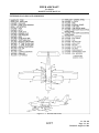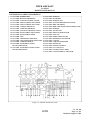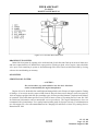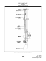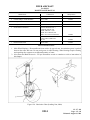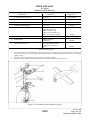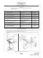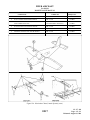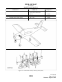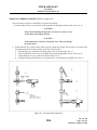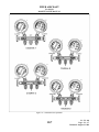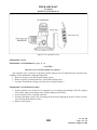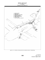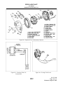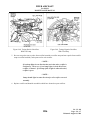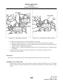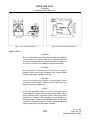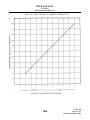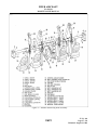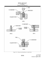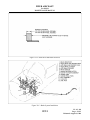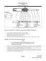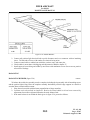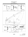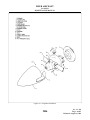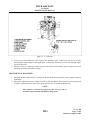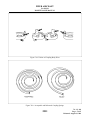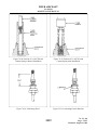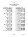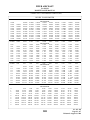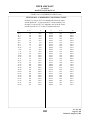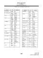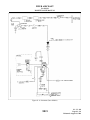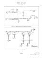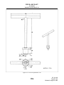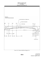
1
DAKOTA
MAINTENANCE MANUAL
CARD 1 OF 3
PA-28-236 DAKOTA
PIPER AIRCRAFT CORPORATION
(PART NUMBER, 761 681 )
1A1
PIPER AIRCRAFT
PA-28-236
MAINTENANCE MANUAL
INTRODUCTION
This Piper Aircraft maintenance manual is prepared in accordance with the General Av i a t i o n
Manufacturers Association format.
1A2
Introduction
Page - 1
Reissued: August 1, 1986
PIPER AIRCRAFT
PA-28-236
MAINTENANCE MANUAL
VENDOR PUBLICATIONS
—WARNING—
When servicing or inspecting vendor equipment installed in Piper
aircraft, it is the user’s responsibility to refer to the applicable
vendor publication.
ENGINE:
Overhaul Manual =
AVCO LYCOMING - OVERHAUL MANUAL
DIRECT DRIVE ENGINE - P/N 60294-7
Avco Lycoming Division
Williamsport, Pa. 17701
Parts Catalog =
AVCO LYCOMING - P/N PC-415
Avco Lycoming Division
Williamsport, Pa. 17701
Operators Handbook = AVCO LYCOMING O-540, IO-540 and
HIO-540 SERIES AIRCRAFT ENGINES
P/N 60297-l0
Avco Lycoming Division
Williamsport, Pa. 1770l
PROPELLER:
Overhaul Instructions = HARTZELL COMPACT CONSTANT SPEED
and FEATHERING PROPELLER - P/N 117-D
Hartzell Propeller Inc.
Piqua, Ohio 45356
MAGNETOS:
Installation, Operation
and Maintenance
Instructions =
BENDIX ELECTRICAL COMPONENTS
DIVISION
Sidney, New York l3838
S-200 Series
Magnetos =
L-526-3 Installation and Maintenance Instructions
L-527-4 Overhaul Instructions
L-528-7 Service Parts List
S-20 Series
Magnetos =
L-205-l0 Overhaul Instructions
L-223-15 Service Parts List
AUTOFLIGHT:
Operational Service
Manual =
CENTURY 21, EDO-AIRE MITCHELL
Box 610, Mineral Wells, Texas 76067
1A3
Introduction
Page - 2
Reissued: August 1, 1986
PIPER AIRCRAFT
PA-28-236
MAINTENANCE MANUAL
PIPER PUBLICATIONS
COMMUNICATIONS:
Removal, Installation
and Maintenance
Instructions =
Radio Service and
Maintenance Manual =
REPAIRS:
A.B.S. Thermoplastic
Landing Gear Wheel
and Strut Fairing
Repair Instructions =
PARTS CATALOG =
PA-28-236
76l 502 AutoControl III B Service Manual
76l 48l AutoFlite II Service Manual
753 771 Pitch Trim Service Manual
761 685 Avionics Wiring Diagram Service Manual
(1978)
76l 713 Avionics Wiring Diagram Service Manual
Vol. I and Vol. II (l979)
76l 708V A.B.S. Thermoplastic Landing Gear
Wheel and Strut Fairing Repair Instruction Manual
761 680
PERIODIC INSPECTION
REPORT FORM =
PA-28-236
230 8l1
PROGRAMMED
INSPECTION MANUAL =
PA-28-236/ 201T
76l 734
1A4
Introduction
Page - 3
Reissued: August 1, 1986
PIPER AIRCRAFT
PA-28-236
MAINTENANCE MANUAL
AEROFICHE EXPLANATION AND REVISION STATUS
The maintenance manual information incorporated in this set of Aerofiche cards has been arranged in
accordance with general specifications for Aerofiche adopted by the General Aviation Manufacturer’s
Association. The information in this Aerofiche maintenance manual is kept current by revisions distributed
periodically. These revisions supersede all previous revisions and are complete Aerofiche card replacements
and supersede Aerofiche cards of the same number in the set.
Identification of revised material:
Revised text and illustrations are indicated by a black vertical line along the left-hand margin opposite
revised or added material. Revision lines indicate only current revisions with changes and additions to existing
text and illustrations. Changes in capitalization, spelling, punctuation, indexing, the physical location of the
material or complete page additions are not identified by revision lines.
A reference and record of the material revised is included in each chapter’s Table of Contents/ Effectivity.
The codes used in the effectivity columns of each chapter are defined as follows:
TABLE OF CONTENTS/EFFECTIVITY CODES
Original Issue:
None
First Revision:
Revision Identification, (1R Month-Year)
Second Revision: Revision Identification, (2R Month-Year)
All subsequent revisions will follow with consecutive revision numbers
such as 3R, 4R, etc., along with the appropriate month-year.
Added Subject:
Revision Identification, (A Month-Year)
Deleted Subject: Revision Identification, (D Month-Year)
1A5
Introduction
Page - 4
Reissued: August 1, 1986
PIPER AIRCRAFT
PA-28-236
MAINTENANCE MANUAL
The information in this Aerofiche maintenance manual was reissued August l, l986. This edition
supersedes all preceding revisions and is a complete Aerofiche card replacement. Revisions to this
maintenance manual 761 681 are as follows:
PN/Effectivity
Publication Date
761 68l (PR860801)
761 681 (IR870223)
761 681 (IR950215)*
Aerofiche Card Effectivity
March 16, 1987*
March 16, 1987
February 15, 1995
All
1
1 and 2
*INTERIM REVISION
Chapters 5, 6, and 27 of Card 1, and Chapter 51 of Card 2 have
been revised. There are no other changes included in this interim
change revision. Please discard your current cards 1 and 2, and
replace them with the revised ones. DO NOT DISCARD CARD 3.
The date on Aerofiche cards must not be earlier than the date noted for the respective card effectivity.
Consult the latest Aerofiche card in this series for current Aerofiche card effectivity.
SERIAL NUMBER INFORMATION
PA-28-236, DAKOTA- l979
Serial Numbers 28-7911001 to 28-7911395 inclusive.
PA-28-236, DAKOTA- l980
Serial Numbers 28-8011001 to 28-8011161 inclusive.
PA-28-236, DAKOTA- 1981
Serial Numbers 28-8111001 to 28-8111105 inclusive.
PA-28-236, DAKOTA- l982
Serial Numbers 28-82l1001 to 28-8211060 inclusive.
PA-28-236, DAKOTA- 1983
Serial Numbers 28-8311001 to 28-8311025 inclusive.
PA-28-236, DAKOTA- l984
Serial Numbers 28-84l1001 to 28-8411031 inclusive.
PA-28-236, DAKOTA- 1985
Serial Numbers 28-8511001 to 28-8511020 inclusive.
PA-28-236, DAKOTA- 1986
Serial Numbers 28-8611001 to 28-8611008 inclusive.
Serial Numbers 2811001 and up*.
*New method of assigning serial numbers used.
1A6
Introduction
Page - 5
Interim Revision: February 15, 1995
PIPER AIRCRAFT
PA-28-236
MAINTENANCE MANUAL
GAMA SYSTEM/CHAPTER INDEX GUIDE
SYST
CHAP
SUB-SYST
SECTION TITLE
AEROFICHE
GRID NO.
4
AIRWORTHINESS LIMITATIONS
1A17
5
TIME LIMITS/MAINT CHECKS
1A21
6
DIMENSIONS AND AREAS
1B12
7
LIFTING AND SHORING
1B20
8
LEVELING AND WEIGHING
1C1
9
TOWING AND TAXIING
1C6
10
PARKING AND MOORING
1C10
11
REQUIRED PLACARDS
1C14
12
SERVICING
1C19
20
STANDARD PRACT - AIRFRAME
1EI
21
ENVIRONMENTAL SYSTEMS
1F12
22
AUTOFLIGHT
1H8
23
COMMUNICATIONS
1H12
24
ELECTRICAL POWER
1H21
25
EQUIPMENT/FURNISHINGS
1J17
27
FLIGHT CONTROLS
1J21
28
FUEL
2A17
32
LANDING GEAR
2B10
33
LIGHTS
2C20
34
NAVIGATION & PITOT/STATIC
2D7
37
VACUUM
2E1
39
ELECTRIC/ELECTRONIC PANELS AND
MULTIPURPOSE PARTS
2E16
1A7
Introduction
Page - 6
Reissued: August 1, 1986
PIPER AIRCRAFT
PA-28-236
MAINTENANCE MANUAL
GAMA SYSTEM/CHAPTER INDEX GUIDE (cont)
SYST
CHAP
SUB-SYST
SECTION TITLE
AEROFICHE
GRID NO.
51
STRUCTURES
2E19
52
DOORS
2F13
55
STABILIZERS
2F21
56
WINDOWS
2G7
57
WINGS
2G12
61
PROPELLER
2H2
70
STANDARD PRACTICES - ENGINE
2H10
71
POWERPLANT
2H14
73
ENGINE FUEL SYSTEM
2I10
74
IGNITION
2I18
77
ENGINE INDICATING
2K2
78
EXHAUST
2K10
79
OIL
2K14
80
STARTING
2K19
91
CHARTS/WIRING DIAGRAMS
3A17
95
SPECIAL PURPOSE EQUIPMENT
3D1
1A8
Introduction
Page - 7
Interim Revision: February 15, 1995
PIPER AIRCRAFT
PA-28-236
MAINTENANCE MANUAL
LIST OF ILLUSTRATIONS
FIGURE NO.
SUBJECT
GRID NO.
6-1.
6-2.
6-3.
7-1.
8-1.
8-2.
8-3.
11-1.
12-1.
12-2.
12-3.
12-4.
12-5.
12-6.
Three View
Station References
Access Plates and Panels
Jacking Arrangement
Weighing Airplane
Leveling Longitudinally
Leveling Laterally
Placards and Decals
Fuel Filter Bowl and Screen
Servicing Points
Main Gear Oleo Struts (Cut-away View)
Lubrication Chart (Landing Gear, Main)
Lubrication Chart (Landing Gear, Nose)
Lubrication Chart (Control System)
12-7.
12-8.
Lubrication Chart (Cabin Door, Baggage Door and Seat)
Lubrication Chart (Power Plant, Propeller and Control
Pivot Points)
Lubrication Chart (Air Conditioning Condenser)
Torque Wrench Extension
Correct Method of Installing Rod End Bearings
Cherrylock Rivet Removal
Hose/Line Markings
Flareless Tube fittings
Cabin Heater, Defroster and Fresh Air System
Air Conditioning System Installation (Typical)
Service Valves
Test Gauge and Manifold Set
Manifold Set Operation
Leak Test Hookup
Evacuation Hookup
Charging Stand
Charging Hookup
Compressor and Fabricated Oil Dipstick
Compressor and Alternator Belt Installation
Magnetic Clutch
Condenser Air Scoop Installation
Expansion Valve
12-9.
20-1.
20-2.
20-3.
20-4.
20-5.
21-1.
21-2.
21-3.
21-4.
21-5.
21-6.
21-7.
21-8.
21-9.
21-10.
21-11.
21-12.
21-13.
21-14.
1A9
1B17
1B18
1B19
1B23
1C4
1C5
1C5
1C17
1C22
1D2
1D6
1D14
1D15
1D16 thru
1D19
1D20
1D21
1D22
1E5
1E5
1E6
1E8
1E9
1F16
1F24
1G5
1G6
1G7
1G8
1G10
1G12
1G14
1G17
1G18
1G21
1G24
1H1
Introduction
Page - 8
Reissued: August 1, 1986
PIPER AIRCRAFT
PA-28-236
MAINTENANCE MANUAL
LIST OF ILLUSTRATIONS
FIGURE NO.
21-15.
21-16.
23-1.
23-2.
23-3.
23-4.
23-5.
24-1.
24-2.
24-3.
24-4.
24-5.
24-6.
24-7.
24-8.
24-9.
24-10.
24 11.
24-12.
24-13.
24-14.
24-15.
24-16.
24-17.
24-18.
24-19.
24-20.
24-21 .
24-22.
24-23.
24-24.
24-25.
24-26.
24-27.
24-28.
24-29.
24-30.
24-31.
24-32.
24-33.
SUBJECT
Components Installation
Overhead Vent System (Not Available with
Air Conditioning)
Avionics Master and Emergency Switch Circuit
Communications Components ELT Schematic
Emergency Locator Transmitter Schematic (Narco)
ELT Portable Folding Antenna (Narco)
ELT Using Fixed Aircraft Antenna (Narco)
Lamp-Bank Load
Exploded View of Alternator (Chrysler)
Checking Field Coil Current Draw
Testing Field Circuit
Testing Positive Rectifiers
Testing Negative Rectifiers
Rectifier End Shield and Stator Assembly
Testing Positive Rectifiers With Test Lamp
Testing Negative Rectifiers With Test Lamp
Rectifier and Heatsink Assembly Removal
Rectifier End Shield Assembly
Testing Stator
Removal of Pulley
Removal of Bearing
Removal of Rectifier End Shield Bearing
Testing Rotor for Ground
Testing Rotor for Opens or Shorts
Installation of Grease Retainer
Installation of Rectifier End Shield Bearing
Installation of Drive End Shield Bearing
Installation of Pulley
Installation of Insulators
Installation of Positive Rectifier Assembly
Installation of Capacitor
Installation of Battery Output Insulator
Installation of Negative Rectifier Assembly
Installation of Stator
Exploded View of Alternator (Prestolite)
Removal of Slip Ring End Bearing
Removal of Rectifier
Removal of Drive End Head
Removal of End Head Bearing
Testing Rotor for Ground
1A10
GRID NO.
1H3
1H5
1H14
1H16
1H16
1H18
1H18
1I10
1I12
1I12
1I12
1I14
1I14
1I14
1I16
1I16
1I17
1I17
1I18
1I18
1I19
1I19
1I20
1I20
1I21
1I21
1I21
1I21
1I23
1I23
1I23
1I23
1J1
1J1
1J3
1J4
1J4
1J4
1J4
1J5
Introduction
Page - 9
Reissued: August 1, 1986
PIPER AIRCRAFT
PA-28-236
MAINTENANCE MANUAL
LIST OF ILLUSTRATIONS (cont)
FIGURE NO.
24-34.
24-35.
24-36.
24-37.
24-38.
24-39.
24-40.
24-41.
25-1.
27-1.
27-2.
27-3.
27-4.
27-5.
27-6.
27-7.
27-8.
27-9.
27-10.
27-11.
27-12.
27-13.
27-14.
27-15.
27-16.
27-17.
27-18.
27-19.
27-20.
27-21.
27-22.
28-1.
28-2.
28-3.
28-4.
28-5.
28-6
32-1.
32-2.
32-3.
32-1.
32-5.
32-6.
SUBJECT
Testing Rotor for Shorts
Installation of Bearing
Installation of Rectifier
Terminal Assembly
Slip Ring End Bearing Assembly
Testing Alternator
Brush Installation
Internal Wiring Diagram
Seat Back Lock
Rod End Installation Method
Control Column Assembly
Aileron Controls (Typical)
Aileron Rigging
Bellcrank Rigging Tool
Aileron Rigging Tool
Rudder and Steering Pedal Assembly
Rudder Controls
Rudder Rigging Tool
Clamping Rudder Pedals
Rudder Rigging
Rudder Travel Adjustments
Rudder Trim Control
Stabilator Controls
Stabilator and Stabilator Trim Travel Adjustments
Stabilator Rigging Tool
Methods of Securing Trim Cables
Stabilator Trim Control
Flap Controls
Flap Step Adjustment
Flap Rigging Tool
Flap Rigging
Fuel System Diagram
Locking Fuel Cap Assembly
Fuel Filter Bowl and Screen
Plunger Fuel Pump
Tolerances, Union Nut and Tubing Nut
Fuel Gauge
Main Gear Oleo Strut Assembly
Main Gear Installation
Nose Gear Oleo Strut Assembly
Nose Gear Installation
Clamping Rudder Pedals in Neutral Position
Rudder Pedals at Neutral Angle
1A11
GRID NO.
1J5
1J7
1J7
1J7
1J8
1J8
1J9
1J9
1J19
1K7
1K9
1K12
1K16
1K16
1K17
1K19
1K21
1K22
1K22
1K22
1L2
1L2
1L4
1L5
1L5
1L8
1L9
1L13
1L15
1L15
1L18
2A20
2A24
2B2
2B2
2B6
2B9
2B17
2B19
2B21
2C1
2C3
2C3
Introduction
Page - 10
Reissued: August 1, 1986
PIPER AIRCRAFT
PA-28-236
MAINTENANCE MANUAL
LIST OF ILLUSTRATIONS (cont.)
FIGURE NO.
32-7.
32-8.
32-9.
32-10.
32-11.
32-12.
32-13.
32-14.
32-15.
32-16.
32-17.
33-1.
34-1.
37-1.
51-1.
51-1a.
51-2.
51-3.
51-4.
51-5.
51-6.
51-7.
51-8.
51-9.
52-1.
55-1.
55-2.
55-3.
55-4.
56-1.
56-2.
57-1.
57-2.
57-3.
61-1.
61-2.
61-3.
61-4.
71-1.
71-2.
71-3.
71-4.
71-5.
71-6 .
73-1.
SUBJECT
GRID NO.
Main Wheel Assembly
Nose Wheel Assembly
Standard Brake Assembly (Cleveland 30-55)
Heavy Duty Brake Assembly (Cleveland 30-65)
Removal and Installation of Anchor Bolts
Brake Disc Minimum Thickness
Brake System Installation
Brake Master Cylinder (Hand/Parking Brake)
Toe Brake Installation
Brake Cylinder 10-30 (Toe Brake)
Brake Cylinder 17000 (Toe Brake)
Strobe Light Connections
Pitot/Static System
Auxiliary Vacuum Pump Installation
Skin Materials and Thickness
Baggage Compartment Inspection Holes Cutout Details
Surface Scratches, Abrasions or Ground-in-Dirt
Deep Scratches, Shallow Nicks and Small Holes
Mixing of Epoxy Patching Compound
Welding Repair Method
Repairing of Cracks
Various Repairs
Repair of Stress Lines
Repair of Impacted Damage
Door Snubber Installation
Empennage Group Installation
Methods of Securing Control Cables
Stabilator Balance
Rudder Balance
Windshield Installation (Typical)
Side Window Installation, Single Pane (Typical)
Wing Installation
Aileron and Flap Installation
Aileron Balance Configuration
Typical Nicks and Removal Method
Propeller Installation
Propeller Governor
Adjustment of Propeller Control
Engine Installation (PA-28-236)
Engine Mount Assembly
Cowling Installation (PA-28-236)
Carburetor Ice Detection System
Carburetor Ice Detector Probe Installation
Rear View of Carburetor Airbox
Carburetor
1A12
2C4
2C6
2C8
2C9
2C10
2C11
2C11
2C13
2C15
2C16
2C16
2D4
2D11
2E12
2E23
2F1
2F5
2F6
2F6
2F8
2F8
2F9
2F11
2F11
2F19
2G1
2G2
2G2
2G5
2G10
2G11
2G15
2G20
2G24
2H4
2H6
2H8
2H8
2I1
2I2
2I3
2I5
2I7
2I9
2I13
Introduction
Page - 11
Interim Revision: February 15, 1995
PIPER AIRCRAFT
PA-28-236
MAINTENANCE MANUAL
LIST OF ILLUSTRATIONS (cont)
FIGURE NO.
73-2.
73-3.
74-1.
74-2.
74-3.
74-4.
74-5.
74-6.
74-7.
74-8.
74-9.
74-10.
74-11.
74-12.
74-13.
74-14.
74-15.
74-16.
74-17.
74-18.
74-19.
74-20.
74-21.
74-22.
74-23.
74-24.
74-25.
74-26.
74-27.
74-28.
74-29.
74-30.
74-31.
74-32.
74-33
78-1.
80-1.
80-2.
80-3.
80-4.
80-5.
80-6.
SUBJECT
Engine Primer
Adjustment of Engine Controls
Height of Spring in Distributor Block Tower
Contact Points
Engine Timing Marks
Timing Light Connected to Magneto
Timing Marks on Magneto Rotor
Painted Tooth Centered in Timing Window
Timing Mark on Rotor Aligned with Pointer
Timing Light Connected to Magneto and Breakers
Cam End View of Magneto
Removing Impulse Coupling
Checking Flyweight to Stop Pin Clearance
Stop Pin Installation Dimension
Checking Flyweight Axial Wear with Drill Shank
Checking Flyweight Radial Wear with Gauge
Points of Coupling Body Wear
Acceptable and Deformed Coupling Springs
Checking Impulse Coupling for Magnetization
Orientation of Spring in Coupling Body
Lifting Inner End of Spring
Checking Harness Lead Continuity
Checking Harness Lead Insulation Resistance
Modified Pliers
Removing Spring From Lead Assembly
Assembly Tool
Using Assembly Tool
Ferrule Positioned Under Braid
Ferrule Seating Tool
Position of 11-8627 Kit and Contact Spring at Start
of Installation
Position of 11-8627 Kit and Contact Spring After
Installation
Lubricating Sleeve
Lubricating Ferrule Shoulder
Removing Spark Plug Frozen to Bushing
Ignition Switch Wire Positions
Exhaust System Inspection Points
Exploded View of Gear Reduction Starting Motor
Turning Starting Motor Commutator
Testing Motor Armature for Shorts
Testing Motor Fields for Grounds
No-Load Test Hookup
Stall-Torque Hookup
1A13
GRID NO.
2I14
2I16
2I24
2I24
2J2
2J2
2J4
2J4
2J4
2J5
2J7
2J9
2J9
2J9
2J10
2J10
2J11
2J11
2J13
2J13
2J13
2J15
2J15
2J15
2J15
2J17
2J17
2J18
2J18
2J19
2J19
2J19
2J19
2J21
2J24
2K12
2K24
2L2
2L2
2L2
2L4
2L4
Introduction
Page - 12
Reissued: August 1, 1986
PIPER AIRCRAFT
PA-28-236
MAINTENANCE MANUAL
LIST OF ILLUSTRATIONS (cont)
FIGURE NO.
95-1.
95-2.
95-3.
95-4.
95-5.
95-6.
95-7.
95-8.
95-9.
95-10.
95-11.
95-12.
95-13.
SUBJECT
Tire Balancer Fixture
Control Surface Balancing Tool
Orifice Replacement Tool
Fabricated Tool for Baggage Door Lock
Retainer Ring Tool
Fabricated Aileron Bellcrank Rigging Tool
Fabricated Rudder Rigging Tool
Fabricated Aileron and Flap Rigging Tool
Fabricated Stabilator Rigging Tool
Charging Stand
York Compressor and Fabricated Oil Dipstick
Ignition Harness Ferrule Seating Tool
Assembly Tool for Ignition Harness Insulating
Sleeve Installation
GRID NO.
3D4
3D5
3D6
3D7
3D7
3D8
3D8
3D9
3D10
3D11
3D11
3D12
3D12
—NOTE—
Refer to Grid No. 3B15 for Electrical Schematic Index.
1A14
Introduction
Page - 13
Reissued: August 1, 1986
PIPER AIRCRAFT
PA-28-236
MAINTENANCE MANUAL
LIST OF CHARTS
CHART NO.
601
1201
1202
2001
2002
2003
2101
2102
2103
2104
2105
2106
2107
2401
2402
2403
2404
2405
2406
2701
2702
2801
2802
3201
3202
3301
3401
3402
3403
3404
3701
5101
6101
7101
7301
7401
7402
7701
7702
7703
7704
SUBJECT
GRID NO.
Leading Particulars and Principal Dimensions
Thread Lubricants
Type of Lubricants
Thread Lubricants
Maximum Distance Between Supports For Fluid Tubing
Types of Metal Corrosion
Troubleshooting (Air Conditioner)
Troubleshooting (Air Conditioning System)
Temperature Pressure
Aluminum Tubing Torque
System Vacuum
Compressor Oil Charge
Blower System Wire Color Codes
Troubleshooting (Alternator)
Troubleshooting (Battery)
Alternator Specifications
Alternator Belt Tension
Hydrometer Reading and Battery Charge Percent
Electrical System Component Loads
Troubleshooting (Surface Controls)
Cable Tension Vs. Ambient Temperature
Troubleshooting (Fuel System)
Transmitter/Fuel Gauge Tolerances
Troubleshooting (Landing Gear)
Nose Gear Alignment Tolerances
Troubleshooting (Electrical System)
Troubleshooting (Rate of Climb Indicator)
Troubleshooting (Altimeter)
Troubleshooting (Airspeed Tubes and Indicator)
Troubleshooting (Magnetic Compass)
Troubleshooting (Vacuum System)
List of Materials (Thermoplastic Repair)
Propeller Torque Limits
Troubleshooting (Engine)
Troubleshooting (Fuel Pressure Gauge)
Troubleshooting (Magneto)
Coupling Torques
Troubleshooting (Manifold Pressure Indicator)
Troubleshooting (Tachometer)
Troubleshooting (Engine Oil Pressure Gauge)
Troubleshooting (Oil Temperature Indicators)
1A15
1B15
1D11
1D12
1E10
1E10
1E15
1F18
1F20
1G2
1G4
1G10
1G17
1H6
1I1
1I6
1J10
1J11
1J13
1J16
1K1
1K6
2A21
2B9
2B14
2C2
2C23
2D12
2D14
2D15
2D19
2E3
2F4
2H7
2H17
2I17
2I22
2J20
2K4
2K5
2K6
2K7
Introduction
Page - 14
Interim Revision: February 15, 1995
PIPER AIRCRAFT
PA-28-236
MAINTENANCE MANUAL
LIST OF CHARTS (cont)
CHART NO.
7705
7706
800l
8002
9101
9102
9103
9104
9105
9106
9107
SUBJECT
Troubleshooting (Exhaust Gas Temperature Gauge)
(Alcor) .
Troubleshooting (Cylinder Head Temperature Gauge)
Troubleshooting (Starter)
Starting Motor Specifications
Flare Fitting Torques
Recommended Nut Torques
Conversion Tables
Decimal Equivalents of Drill Sizes
List of Consumable Materials
Electrical Wire Coding
Electrical Symbols
1A16
GRID NO.
2K8
2K9
2K22
2L6
3A19
3A20
3A23
3B4
3B5
3B13
3B14
Introduction
Page - 15
Reissued: August 1, 1986
CHAPTER
AIRWORTHINESS
LIMITATIONS
1A17
PIPER AIRCRAFT
PA-28-236
MAINTENANCE MANUAL
CHAPTER 4 - AIRWORTHINESS LIMITATIONS
TABLE OF CONTENTS/EFFECTIVITY
CHAPTER
SECTION
SUBJECT
4-00-00
4-00-00
SUBJECT
AIRWORTHINESS LIMITATIONS
General
1A18
GRID
NO.
EFFECTIVITY
1A20
1A20
4 - Cont./Effec.
Page - 1
Reissued: August 1, 1986
PIPER AIRCRAFT
PA-28-236
MAINTENANCE MANUAL
THIS PAGE INTENTIONALLY LEFT BLANK
1A19
PIPER AIRCRAFT
PA-28-236
MAINTENANCE MANUAL
AIR WORTHINESS LIMITATIONS
GENERAL
Airworthiness limitations are FAA approved and specify inspections and maintenance required under Parts
43 and 9l of Federal Aviation Regulations.
Limitations relating to fatigue life of the airplane and its components are as follows:
l. Safe life of airframe structure will be released when information becomes available.
2. Safe life limit of propeller blades is unlimited. (Refer to latest revision of Hartzell Service Letter No.
6l for l500 hour overhaul.)
—NOTE—
Refer to the Limitations in the Pilot’s Operating Handbook and
FAA Approved Airplane Flight Manual for a detail of flight
limitations. Mandatory replacement times and inspection
intervals of life limited parts are contained in chapter 5 of this
manual.
—END—
1A20
4-00-00
Page - 4-01
Reissued: August 1, 1986
CHAPTER
TIME LIMITS/MAINT CHECKS
1A21
PIPER AIRCRAFT
PA-28-236
MAINTENANCE MANUAL
CHAPTER 5 - TIME LIMITS/MAINTENANCE CHECKS
TABLE OF CONTENTS/EFFECTIVITY
CHAPTER
SECTION
SUBJECT
SUBJECT
GRID
NO.
5-00-00
GENERAL
1 A24
5-10-00
5-11-00
5-12-00
5-13-00
TIME LIMITS
Inspection Requirements
Preflight Checks
Overlimits Inspection
1A24
1A24
1A24
1A24
5-20-00
5-21-00
5-22-00
SCHEDULED MAINTENANCE
Periodic Inspections
Programmed Inspection
1B1
1B1
1B11
5-50-00
5-51-00
UNSCHEDULED MAINTENANCE CHECKS
Special Inspections as Required, Upon Condition
1B11
1B11
1A22
EFFECTIVITY
5 - Cont./Effec.
Page - 1
Reissued: August 1, 1986
PIPER AIRCRAFT
PA-28-236
MAINTENANCE MANUAL
THIS PAGE INTENTIONALLY LEFT BLANK
1A23
PIPER AIRCRAFT
PA-28-236
MAINTENANCE MANUAL
GENERAL
This chapter provides instructions for conducting inspections. These inspections are described in
Inspection Requirements and Preflight Checks. Repair or replacement instructions for components found to be
unserviceable at inspection are found in the section covering the applicable aircraft system.
—WARNING—
When working on engines ground magneto primary circuits
before performing any operation.
TIME LIMITS
INSPECTION REQUIREMENTS
Required inspection procedures are listed in Periodic Inspections. Inspection procedures are broken down
into eight major groups. These are: Propeller, Engine, Cabin, Fuselage and Empennage, Wing, Landing Gear,
Operational Inspection and General. The first column in each group lists the inspection or procedure to be
performed. The second column is divided into four columns indicating the required inspection intervals of 50
hours, 100 hours, 500 hours, and 1000 hours. Each inspection or operation is required at each inspection
interval as indicated by a circle (O). If an item is not entirely accessible or must be removed, refer to the
applicable section of this manual for instructions on removal of the item. When performing inspections, use
form P/N 230 8ll furnished by Piper factory service department; available through Piper dealers or distributors.
Refer to latest Piper Parts Price List Aerofiche for current revision date.
PREFLIGHT CHECKS
—CAUTION—
In addition to inspection intervals required in Periodic
Inspections, preflight checks must be performed as described in
the following paragraph.
The airplane must be given a thorough preflight check. The pilot or mechanic must include the preflight
check as a normal procedure necessary for aircraft safe operation. Refer to the Pilot’s Operating Handbook for
a checklist.
.
OVERLIMITS INSPECTION
If the airplane has been operated so that any of its components have exceeded their maximum operational
limits, check with appropriate manufacturer.
1A24
5 - 13 - 00
Page - 5-01
Reissued: August 1, 1986
PIPER AIRCRAFT
PA-28-236
MAINTENANCE MANUAL
SCHEDULED MAINTENANCE
PERIODIC INSPECTIONS
—NOTE—
Perform all inspections or operations at each inspection interval as
indicated by a circle (O).
Inspection Time (HRS)
Nature of Inspection
50
100
500
1000
O
O
O
O
O
O
O
O
O
O
O
O
O
O
O
O
O
O
O
O
O
O
O
O
O
O
O
O
O
O
O
O
O
O
O
O
O
O
O
O
O
O
O
O
O
O
O
O
O
O
O
O
O
O
A. PROPELLER GROUP
l.
2.
3.
4.
5.
6.
7.
8.
9.
l0.
Inspect spinner and back plate.................................................................................
Inspect blades for nicks and cracks .........................................................................
Inspect for grease and oil leaks................................................................................
Lubricate propeller. (Refer to chapter l2.)...............................................................
Inspect spinner mounting brackets ..........................................................................
Inspect propeller mounting bolts and safety. (Check torque if safety is
broken.)....................................................................................................................
Inspect hub parts for cracks and corrosion..............................................................
Rotate blades of constant speed propeller and check for tightness in hub
pilot tube..................................................................................................................
Remove constant speed propeller; remove sludge from propeller and
crankshaft.................................................................................................................
Inspect complete propeller and spinner assembly for security, chafing,
cracks, deterioration, wear, and correct installation. ...............................................
B. ENGINE GROUP
WARNING:
NOTE:
l.
2.
3.
4.
5.
6.
Ground magneto primary circuit before working on
engine.
Read Notes 4 and l9 prior to completing this inspection group.
Remove engine cowl and inspect for damage .........................................................
Clean and check cowling for cracks, distortion, and loose or missing
fasteners...................................................................................................................
Drain oil sump. (See Note 5 )..................................................................................
Clean suction oil strainer at oil change. (Check strainer for foreign particles.)......
Clean pressure oil strainer or change full-flow (cartridge type) oil filter element.
(Check strainer or element for foreign particles.)....................................................
Inspect oil temperature sender unit for leaks and security ......................................
1B1
O
5-21-00
Page -5-02
Reissued: August 1, 1986
PIPER AIRCRAFT
PA-28-236
MAINTENANCE MANUAL
PERIODIC INSPECTIONS (cont)
—NOTE—
Perform all inspections or operations at each inspection interval as
indicated by a circle (O).
Nature of Inspection
B. ENGINE GROUP (cont)
7. Inspect oil lines and fitting for leaks, security, chafing, dents, and cracks.
(See Note 7.)............................................................................................................
8. Clean and inspect oil radiator cooling fins..............................................................
9. Remove and flush oil radiator .................................................................................
10. Fill engine with oil per lubrication chart. (Refer to chapter l2.)..............................
CAUTION:
Do not contaminate the vacuum pump with cleaning
fluid. (Ref: Latest revision of Lycoming Service
Instruction No. l22l.)
11. Clean engine ............................................................................................................
12. Inspect condition of spark plugs. (Clean and adjust gap as required, adjust
per latest revision of Lycoming Service Instruction No. 1042.)..............................
(See Note 14.) .........................................................................................................
NOTE:
If fouling of spark plugs has been apparent, rotate
bottom plugs and upper plugs.
13. Inspect spark plug cable leads and ceramics for corrosion and deposits.................
14. Check cylinder compression. (Ref: Latest revision of AC 43.l3-l.)........................
15. Inspect cylinders for cracked or broken fins............................................................
16 Inspect rocker box covers for evidence of oil leaks. If found, replace
gasket; tighten cover screws to a torque of 50 inch-pounds. (See Note 12.)...........
NOTE:
Lycoming requires a valve inspection be made after
every 400 hours of operation. (See Note l l.)
17. Inspect ignition harness and insulators for high tension leakage and continuity ....
18. Inspect magneto points for condition and proper clearance....................................
19. Inspect magneto for oil leakage ..............................................................................
20. Inspect breaker felts for proper lubrication .............................................................
21. Inspect distributor block for cracks, burned areas, corrosion, and
height of contact springs .........................................................................................
22. Check magnetos to engine timing ...........................................................................
23. Overhaul or replace magnetos. (See Note 6.)
24. Remove air filter and tap gently to remove dirt particles. (Replace as
required.)..................................................................................................................
25. Drain carburetor and clean inlet line fuel strainer...................................................
26. Inspect condition of carburetor heat air-door and box. (See Note l3.) ...................
27. Inspect vent lines for evidence of fuel or oil seepage..............................................
28. Inspect intake seals for leaks and clamps for tightness ...........................................
29. Inspect all air inlet duct hoses. (Replace as required.) ............................................
1B2
Inspection Time (HRS)
50
100
500
1000
O
O
O
O
O
O
O
O
O
O
O
O
O
O
O
O
O
O
O
O
O
O
O
O
O
O
O
O
O
O
O
O
O
O
O
O
O
O
O
O
O
O
O
O
O
O
O
O
O
O
O
O
O
O
O
O
O
O
O
O
O
O
O
O
O
O
O
O
O
O
O
O
O
5 - 21 - 00
Page -5 - 03
Reissued: August 1, 1986
PIPER AIRCRAFT
PA-28-236
MAINTENANCE MANUAL
PERIODIC INSPECTIONS (cont)
—NOTE—
Perform oll inspections or operations at each inspection interval as
indicated by a circle (O).
Nature of Inspection
B.
30.
31.
32.
33.
34.
35.
36.
37.
38.
39.
40.
41.
42.
43.
44.
45.
46.
47.
48.
49.
50.
51.
52.
53.
54.
55.
56.
ENGlNE GROUP (cont)
Inspect condition of flexible fuel lines ...................................................................
Replace flexible fuel lines. (See Note 6.)................................................................
Inspect fuel system for leaks....................................................................................
Clean screens in electric fuel pump(s) and check operation (engine and
electric)....................................................................................................................
Remove and clean fuel filter bowl and screen. (Clean at least every 90
days.)........................................................................................................................
Inspect vacuum pump and lines...............................................................................
Overhaul or replace vacuum pump. (See Note 6.)...................................................
Inspect throttle, carburetor heat, mixture and propeller governor controls
for security, travel, and operating conditions...........................................................
Inspect exhaust stacks, connections, and gaskets. (Refer to chapter 78.)
(Replace gaskets as required.) .................................................................................
Inspect muffler, heat exchange and baffles. (Refer to chapter 78.).........................
Check recommended time for replacement of muffler per chapter 78....................
Inspect breather tube for obstructions and security.................................................
Inspect crankcase for cracks, leaks, and security of seam bolts..............................
Inspect engine mounts for cracks and loose mountings ..........................................
Inspect all engine baffles .........................................................................................
Inspect all wiring connected to engine or accessories.............................................
Inspect rubber engine mount bushings for deterioration. (Replace as
required.)..................................................................................................................
Inspect fire wall seals ..............................................................................................
Inspect condition and tension of alternator drive belt. (Refer to chapter 2l.)..........
Lubricate alternator and compressor idler pulleys (if installed)
per lubrication chart.................................................................................................
Inspect condition of alternator and starter...............................................................
Inspect security of alternator mounting ..................................................................
Check air conditioning compressor oil level (See Note 8)
Inspect condition of compressor belt and tension. (Refer to chapter 2l.)................
Inspect compressor clutch security and wiring. (See Note 9.) ................................
Inspect security of compressor mounting ...............................................................
Check fluid in brake reservoir. (Fill as required.)....................................................
1B3
Inspection Time (HRS)
50
100
500
1000
O
O
O
O
O
O
O
O
O
O
O
O
O
O
O
O
O
O
O
O
O
O
O
O
O
O
O
O
O
O
O
O
O
O
O
O
O
O
O
O
O
O
O
O
O
O
O
O
O
O
O
O
O
O
O
O
O
O
O
O
O
O
O
O
O
O
O
O
O
O
O
O
O
O
O
O
O
5 - 21 - 00
Page -5 - 04
Reissued: August 1, 1986
PIPER AIRCRAFT
PA-28-236
MAINTENANCE MANUAL
PERIODIC INSPECTIONS (cont)
—NOTE—
Perform all inspections or operations at each inspection interval as
indicated by a circle (O).
Inspection Time (HRS)
Nature of Inspection
B. ENGINE GROUP (cont)
57. Lubricate all controls. (Refer to chapter l2.)............................................................
58. Reinstall engine cowl...............................................................................................
50
100
500
1000
O
O
O
O
O
O
O
O
O
O
O
O
O
O
O
O
O
O
O
O
O
O
O
O
O
O
O
O
O
O
O
O
O
O
O
O
O
O
O
O
O
O
O
O
O
O
O
O
O
O
O
O
O
O
O
O
O
O
O
O
O
C. CABIN GROUP
1.
2.
3.
4.
5.
6.
7.
8.
9.
10.
11.
12.
13.
14.
15.
16.
17.
18.
Inspect cabin entrance door and windows for damage and operation.....................
Inspect upholstery for tears......................................................................................
Inspect seats, seat belts, security brackets, and bolts...............................................
Check trim operation ...............................................................................................
Check rudder pedals ................................................................................................
Inspect parking brake and brake handle for operation and cylinder
leaks.........................................................................................................................
Inspect control wheels, column, pulleys, and cables...............................................
Inspect flap control cable attachment bolt (See latest revision of Piper Service
Bulletin 965)............................................................................................................
Inspect landing, navigation, cabin, and instrument lights .......................................
Inspect instruments, lines and attachments..............................................................
Inspect gyro operated instruments and electric turn and bank. (Overhaul
or replace as required.) ............................................................................................
Clean or replace vacuum regulator filter.................................................................
Inspect altimeter. (Calibrate altimeter system in accordance with
FAR 9l.170 if appropriate.)......................................................................................
Check operation of fuel selector valve ....................................................................
Inspect condition of heater controls and ducts ........................................................
Inspect condition and operation of air vents............................................................
Inspect condition of air conditioning ducts .............................................................
Remove and clean air conditioning evaporator filter ..............................................
1B4
O
5 - 21 - 00
Page 5 - 05
Interim Revision: February 15, 1995
PIPER AIRCRAFT
PA-28-236
MAINTENANCE MANUAL
PERIODIC INSPECTIONS (cont)
—NOTE—
Perform all inspections or operations at each inspection interval as
indicated by a circle (O).
Inspection Time (HRS)
Nature of Inspection
50
D. FUSELAGE AND EMPENNAGE GROUP
l.
2.
3.
4.
5.
6.
7.
8.
9.
l0.
l l.
l2.
l3.
l4.
l5.
l6.
17.
18.
19.
20.
21.
22.
23.
23a.
24.
25.
26.
27.
28.
29.
30.
Remove inspection plates and panels (See Note 21.)..............................................
Inspect baggage door, latch, and hinges..................................................................
Inspect battery, box, and cables. Check at least every 30 days. Flush box
as required and fill battery per instructions on box .................................................
Inspect electronic installation..................................................................................
Inspect bulkheads and stringers for damage............................................................
Inspect antenna mounts and electric wiring.............................................................
Inspect air conditioning system for freon leaks.......................................................
Inspect freon level in sight gauge of receiver-dehydrator. (Refer to chapter 2l.)....
Inspect air conditioning condenser air scoop rigging .............................................
Inspect fuel lines, valves, and gauges for damage and operation............................
Clean screens in fuel pumps ...................................................................................
Remove, drain, and clean fuel strainer bowl and screen. Drain and clean
at least every 90 days...............................................................................................
Inspect security of all lines......................................................................................
Inspect vertical fin and rudder surfaces for damage................................................
Inspect rudder hinges, horn, and attachments for damage and operation................
Inspect rudder control stop to insure stop has not loosened
and locknut is tight...................................................................................................
Inspect vertical fin attachments...............................................................................
Inspect rudder hinge bolts for excess wear. (Replace as required.).........................
Inspect stabilator surfaces for damage.....................................................................
Inspect stabilator, tab hinges, horn, and attachments for damage and operation.....
Inspect stabilator attachments. (See latest revision of Piper Service
Bulletin 856)............................................................................................................
Inspect stabilator and tab hinge bolts and bearings for excess wear.
(Replace as required.)..............................................................................................
Inspect stabilator control stop. Ensure stop has not loosened and jam nut is tight..
Inspect stabilator trim mechanism...........................................................................
Inspect fuselage wing attach fittings for corrosion, general condition and security.
(See latest revision of Piper Service Bulletin 977.).................................................
Inspect cables, aileron, rudder, stabilator, stabilator trim, turnbuckles, guides,
and pulleys for safety, damage, and operation (See Note 22)..................................
Inspect all cable tensions (use tensiometer). (See Note l7.)....................................
Clean and lubricate stabilator trim drum screw.......................................................
Clean and lubricate all exterior needle bearings......................................................
Lubricate per lubrication chart. (Refer to chapter l2.).............................................
Inspect anti-collision light for security and operation.............................................
1B5
O
O
O
O
O
100
500
1000
O
O
O
O
O
O
O
O
O
O
O
O
O
O
O
O
O
O
O
O
O
O
O
O
O
O
O
O
O
O
O
O
O
O
O
O
O
O
O
O
O
O
O
O
O
O
O
O
O
O
O
O
O
O
O
O
O
O
O
O
O
O
O
O
O
O
O
O
O
O
O
O
O
O
O
O
O
O
O
O
O
O
O
O
O
O
O
O
O
O
5 - 21 - 00
Page 5 - 06
Interim Revision: February 15, 1995
PIPER AIRCRAFT
PA-28-236
MAINTENANCE MANUAL
PERIODIC INSPECTIONS (cont)
—NOTE—
Perform all inspections or operations at each inspection interval as
indicated by a circle (O).
Inspection Time (HRS)
Nature of Inspection
50
D. FUSELAGE AND EMPENNAGE GROUP (cont)
31. Inspect security of Autopilot bridle cable clamps. (See Note 10.)..........................
32. Inspect all control cables, air ducts, electrical leads, lines, radio antenna
leads, and attaching parts for security, routing, chafing, deterioration,
wear, and correct installation...................................................................................
33. Inspect elt installation, condition of battery, and antenna. (See latest
revision of Piper Service Letter No. 820.)...............................................................
34. Reinstall inspection plates and panels .....................................................................
E. WING GROUP
l.
Remove inspection plates and fairings....................................................................
2. Inspect surfaces and tips for damage, loose rivets, and condition of
walkway...................................................................................................................
3. Inspect aileron hinges and attachments ..................................................................
4. Inspect aileron control stops to insure stop has not loosened and locknut
is tight ......................................................................................................................
5. Inspect aileron cables, pulleys, and bellcranks for damage and operation..............
6. Inspect flaps and attachments for damage and operation .......................................
7. Inspect condition of bolts used with hinges. (Replace as required.) .......................
8. Lubricate per lubrication chart. (Refer to chapter l2.) ............................................
9. Inspect forward and aft wing attach fittings for corrosion, general condition and
security. (See latest revision of Piper Service Bulletin 977.)...................................
9a. Inspect wing attachment bolts and brackets ............................................................
10. Inspect fuel tanks and lines for leaks and water. (See Note l6.) .............................
11. Fuel tanks marked for capacity ...............................................................................
12. Fuel tanks marked for minimum octane rating........................................................
13. Inspect fuel cell vents. (See Note l5.) .....................................................................
14. Inspect all control cables, air ducts, electrical leads, lines, and attaching
parts for security, routing, chafing, deterioration, wear, and correct
installation ...............................................................................................................
15. Reinstall inspection plates and fairings ...................................................................
F. LANDING GEAR GROUP
1. Inspect oleo struts for proper extension. (Check fuid level as required.) ...............
2. Inspect nose gear steering control and travel...........................................................
3. Inspect wheels for alignment ..................................................................................
4. Put airplane on jacks ...............................................................................................
5. Inspect tires for cuts, uneven or excessive wear, and slippage ...............................
1B6
O
O
100
500
1000
O
O
O
O
O
O
O
O
O
O
O
O
O
O
O
O
O
O
O
O
O
O
O
O
O
O
O
O
O
O
O
O
O
O
O
O
O
O
O
O
O
O
O
O
O
O
O
O
O
O
O
O
O
O
O
O
O
O
O
O
O
O
O
O
O
O
O
O
O
O
O
O
O
O
O
5 - 21 - 00
Page 5 - 07
Interim Revision: February 15, 1995
PIPER AIRCRAFT
PA-28-236
MAINTENANCE MANUAL
PERIODIC INSPECTIONS (cont)
—NOTE—
Perform all inspections or operations at each inspection intcrval as
indicated by a circle (O).
Nature of Inspection
F.
6.
7.
8.
9.
10.
11.
12.
13.
14.
15.
LANDING GEAR GROUP (cont)
Remove wheels. Clean, check, and repack bearings ...............................................
Inspect wheels for cracks, corrosion, and broken bolts...........................................
Check tire pressure. .................................................................................................
Inspect brake lining and disc for condition and wear..............................................
Inspect brake backing plates for condition and wear...............................................
Inspect brake lines ...................................................................................................
Inspect shimmy dampener.......................................................................................
Inspect gear forks for damage..................................................................................
Inspect oleo struts for fluid leaks and scoring.........................................................
Inspect gear struts, attachments, torque links, and bolts for condition
and security..............................................................................................................
16. Inspect all hydraulic lines, electrical leads, and attaching parts for security,
routing, chafing, deterioration, wear, and correct installation ................................
17. Lubricate per lubrication chaft. (Refer to chapter l2.).............................................
18. Remove airplane from jacks ...................................................................................
G. OPERATIONAL INSPECTION
1. Check fuel pump and fuel tank selector...................................................................
2. Check fuel quantity, pressure, and flow readings ...................................................
3. Check oil pressure and temperature ........................................................................
4. Check alternator output............................................................................................
5. Check manifold pressure .........................................................................................
6. Check carburetor heat .............................................................................................
7. Check parking brake................................................................................................
8. Check operation of auxiliary vacuum pump system. (If installed.)
(See Note 20.)..........................................................................................................
1B7
Inspection Time (HRS)
50
100
500
1000
O
O
O
O
O
O
O
O
O
O
O
O
O
O
O
O
O
O
O
O
O
O
O
O
O
O
O
O
O
O
O
O
O
O
O
O
O
O
O
O
O
O
O
O
O
O
O
O
O
O
O
O
O
O
O
O
O
O
O
O
O
O
O
O
O
O
O
O
O
O
O
O
5 - 21 - 00
Page -5 - 08
Reissued: August 1, 1986
PIPER AIRCRAFT
PA-28-236
MAINTENANCE MANUAL
PERIODIC INSPECTIONS (cont)
—NOTE—
Perform all inspections or operations at each inspection interval as
indicated by a circle (O).
Nature of Inspection
Inspection Time (HRS)
50
100
500
1000
OPERATIONAL INSPECTION (cont)
Check vacuum gauge...............................................................................................
Check gyros for noise and roughness......................................................................
Check cabin heater operation...................................................................................
Check magneto switch operation.............................................................................
Check magneto rpm variation..................................................................................
Check throttle and mixture operation......................................................................
Check propeller smoothness....................................................................................
Check propeller governor action .............................................................................
Check engine idle ....................................................................................................
Check electronic equipment operation ....................................................................
Check air conditioner compressor clutch operation ................................................
Check air conditioner condenser scoop operation...................................................
Check operation of autopilot and automatic trim. (See Note 18.)...........................
O
O
O
O
O
O
O
O
O
O
O
O
O
O
O
O
O
O
O
O
O
O
O
O
O
O
O
O
O
O
O
O
O
O
O
O
O
O
O
O
O
O
O
O
O
O
O
O
O
O
O
O
H. GENERAL
1. Aircraft conforms to FAA specification..................................................................
2. All FAA airworthiness directives complied with ....................................................
3. All manufacturers service bulletins and letters complied with................................
4. Check for proper flight manual................................................................................
5. Aircraft papers in proper order................................................................................
O
O
O
O
O
O
O
O
O
O
O
O
O
O
O
O
O
O
O
O
G.
9.
10.
11.
12.
13.
14.
15.
16.
17.
18.
19.
20.
21.
1B8
5 - 21 - 00
Page -5 - 09
Reissued: August 1, 1986
PIPER AIRCRAFT
PA-28-236
MAINTENANCE MANUAL
PERIODIC INS7PECTIONS (cont)
NOTES:
1. All inspections or operations are required at each inspection interval as indicated by a (O). Both annual
and l00 hour inspections are complete airplane inspections, and are identical in scope. The 500 and
100 hour inspections are extensions of the annual or l00 hour inspection, but require a more detailed
examination of the airplane, and overhaul or replacement of some major components. Inspections must
be accomplished by persons authorized by the FAA.
2. Piper service bulletins are of special importance and must be complied with promptly.
3. Piper service letters are product improvements and service hints pertaining to servicing. Service letters
should be given careful attention.
4. Power plant inspections are based on the engine manufacturers operators manual.
5. Intervals between oil changes can be increased as much as 100% provided the full flow cartridge type
oil filter element is replaced each 50 hours of operation and the specified octane fuel is used. If fuel
other than specified octane rating for the power plant is used, refer to latest revision of Lycoming
Service Letter No. Ll85 for additional information and recommended service procedures.
6. For engine overhaul, refer to the latest revision of Lycoming Service Letter No. 20l.
7. Replace flexible oil lines as required per latest revision of Lycoming Service Bulletin No. 240.
8. Do not check compressor oil level unless a freon leak has occurred.
9. Clean any traces of oil from clutch surface.
10. Check security and condition of autopilot servo bridle cables, clamps, and shear pin in accordance
with the latest revision of Piper Service Letter No. 695.
11. Remove the rocker box covers after every 400 hours of engine operation, and check for freedom of
valve rockers when valves are closed. Check for evidence of abnormal wear or broken parts in the area
of the valve tips, valve keeper, springs, and spring seat. If any indications are found, the cylinder and
all components must be removed (including the piston and connecting rod assembly). Inspect for
further damage. Replace any parts that do not conform to limits shown in the latest revision for
Lycoming Service Table of Limits No. SSPl776.
12. Check cylinders for evidence of excessive heat. This condition is indicative of internal damage to the
cylinder. If found, determine and correct its cause before the aircraft is returned to service.
Heavy discoloration and appearance of seepage at the cylinder head and barrel attachment area
is usually due to emission of thread lubricant used during assembly, or by slight gas leakage which
stops after the cylinder has been in service for awhile. This condition is neither harmful nor
detrimental to engine performance and operation. If proven that leakage exceeds these conditions,
replace the cylinder.
13. Check throttle body attaching screws for tightness. The correct torque for these screws is 40 to 50
inch-pounds.
14. When using alternate fuels, refer to latest revision of Lycoming Service Letter No. L185 for additional
information and recommended service procedures.
15. Replace fuel tank vent line flexible connections as required. Time in service must not exceed 1000
hours.
1B9
5 - 21 - 00
Page - 5 - 10
Reissued: August 1, 1986
PIPER AIRCRAFT
PA-28-236
MAINTENANCE MANUAL
PERIODIC INSPECTIONS (cont)
NOTES (cont):
16. Replace flexible fuel tank supply hose at time of engine overhaul.
17. Maintain cable tensions specified in chapter 27.
18. Refer to list of vendor and Piper publications in the front of the maintenance manual for appropriate
subject manual part number.
19. Refer to Lycoming Service Bulletin 469.
20. The airborne auxiliary vacuum pump/motor (4A3-1) must be removed from service at 500 hours
operating time as indicated on the elapsed time indicator, or at l0 years of installed time in the aircraft,
whichever comes first.
—NOTE—
100 Hour/Annual Inspection Report printed copies are available
through Piper service sales - under Piper part number 230 811.
refer to latest revision of Piper Parts Price List Aerofiche (last
card in set) for latest revision to this report.
21. If not already installed, add access panels per instructions in Chapter 51. See latest revision of Piper
Service Bulletin 977.
22. Special care should be taken to inspect stabilator control cables beneath aft baggage compartment
floor. Add access panels per instructions in Chapter 51 to ease this inspection.
1B10
5 - 21 - 00
Page 5 - 11
Interim Revision: February 15, 1995
PIPER AIRCRAFT
PA-28-236
MAINTENANCE MANUAL
PROGRAMMED INSPECTION
The programmed inspection permits best aircraft utilization by scheduling inspections through use of
planned inspection schedules. This programmed inspection schedule is available in manual form from Piper
service sales under Piper part number 76l 734.
UNSCHEDULED MAINTENANCE CHECKS
SPECIAL INSPECTIONS AS REQUlRED (ON CONDITION)
Special inspections supplement scheduled inspections as outlined in periodic inspections, to include
inspections required at intervals not compatible with airframe operating time or inspection intervals. These
include:
l. Inspections required because of special conditions or incidents that are required to ensure further safe
flight.
2. Hard or Overweight Landing. This inspection must be performed after rough landing or after landing
while aircraft is known to exceed design landing weight. Check following areas and items:
a. Wings - for wrinkled skins and loose or missing rivets.
b. Fuel leaks around fuel tanks.
c. Wing spar webs, bulkheads, wing and fuselage stringers, and skins for any signs of overstress or
damage.
d. An alignment check to clarify any doubt of damage.
3. Severe Turbulence Inspection. Check same items and locations as for Hard or Overweight Landings as
well as the following:
a. Top and bottom fuselage skins for loose or missing rivets and wrinkled skins.
b. Empennage skins and attachments.
4. Engine overspeed, sudden stoppage, loss of oil, overtemperature, and lightning strike.
Check with Avco Lycoming for necessary corrective action.
—END—
1B11
5 - 51 - 00
Page - 5 - 12
Reissued: August 1, 1986
CHAPTER
DIMENSIONS AND AREAS
1B12
PIPER AIRCRAFT
PA-28-236
MAINTENANCE MANUAL
CHAPTER 6 - DIMENSIONS AND AREAS
TABLE OF CONTENTS/EFFECTIVITY
CHAPTER
SECTION
SUBJECT
SUBJECT
GRID
NO.
6-10-00
DIMENSIONS
1B15
6-20-00
STATION REFERENCE LINES
1B18
6-30-00
ACCESS AND INSPECTION PROVISIONS
1B19
1B13
EFFECTIVITY
6 - Cont./Effec.
Page - 1
Reissued: August 1, 1986
PIPER AIRCRAFT
PA-28-236
MAINTENANCE MANUAL
THIS PAGE INTENTIONALLY LEFT BLANK
1B14
PIPER AIRCRAFT
PA-28-236
MAINTENANCE MANUAL
DIMENSIONS
Airplane dimensions and specifications are shown in figure 6-1 and listed in chart 601.
CHART 601. LEADING PARTICULARS AND PRINCIPAL DIMENSIONS
MODEL
PA-28-236
ENGINE
Manufacturer
Model
Rated horsepower at propeller rpm
Oil sump capacity
Fuel, aviation grade, minimum
Magneto, Bendix
Magneto timing
Approved spark plugs
Avco-Lycoming
0-540-J3A5D
235 hp/2400 rpm
l2 U.S. qts.
l00/ 130
D6LN-203l, 303l, 3000
23° btc
Refer to the latest issue of Avco
Lycoming Service Instructions
No. 1042
0.017 to 0.021
1-4-5-2-3-6
MA4-5
MZ4206
ALY-64221
Spark plug gap
Firing order
Carburetor, Marvel-Schebler
Starter, Prestolite, l2 Volt
Alternator, Prestolite (60 Amp)
36566242
41118103
Alternator, Chrysler (60 Amp)
Alternator, Chrysler (60 Amp)
PROPELLER (CONSTANT SPEED)
Manufacturer
Hub, model
Blade, model
Diameter max./min.
Governor control
Governor model
Hartzell
HC-F2YR-l( )
F8468A-4R
80.0 In.
Hartzell
F-4-2l( )
1Airconditioned aircraft
2Non-Airconditioned aircraft s/n: 28-7911001 to 28-7911087
3Non-Airconditioned aircraft s/n: 28-7911088 and up
1B15
6 - 10 - 00
Page - 6 - 01
Reissued: August 1, 1986
PIPER AIRCRAFT
PA-28-236
MAINTENANCE MANUAL
CHART 601. LEADING PARTICULARS AND PRINCIPAL DIMENSIONS (CONT)
FUEL SYSTEM
CAPACITY
Left wing tank
Right wing tank
Total
Total unusable
38.5 gal.
38.5 gal.
77 gal.
5 gal.
LANDING GEAR
Type
Shock strut type
Wheel tread
Wheel base
Turning radius, nose wheel
Nose wheel travel
Wheel, nose
Fixed
Combination air-oil
10.0 Ft.
6 Ft. 6.06 Inches
l3 Ft.
30° +/- l° left & right
McCauley D30665 or Cleveland
40-56, 6:00x6
Cleveland 40-86B, 6:00 x 6
Cleveland 40-90A, 6:00 x 6
Cleveland 30-55, single disc,
single piston
Cleveland 30-65, single disc,
double piston
6:00 x 6, 6 ply rating
6:00 x 6, 6 ply rating
6:00 x 6, 8 ply rating
28-30 psi
35-40 psi
35-40 psi
Wheel, main
Wheel, main, heavy duty
Brake type, standard
Brake type, heavy duty
Tires, nose
Tires, main
Tires, main, heavy duty
Tire pressure, nose
Tire pressure, main
Tire pressure, main, heavy duty
1B16
6 - 10 - 00
Page - 6 - 02
Reissued: August 1, 1986
PIPER AIRCRAFT
PA-28-236
MAINTENANCE MANUAL
Figure 6-l. Three View
1B17
6 - 10 - 00
Page - 6 - 03
Reissued: August 1, 1986
PIPER AIRCRAFT
PA-28-236
MAINTENANCE MANUAL
STATION REFERENCE LINES
To facilitate location of various components which require maintenance and servicing, a method utilizing
fuselage station (F. S.), wing station or buttock line (BL), and water line (WL) is frequently used in this
manual. (Refer to figure 6-2.) Fuselage stations, buttock lines, and water lines are reference points measured in
inches in a vertical or horizontal direction from a given reference line. Fuselage station 0 is 78.4 inches
forward of wing leading edge or 44.5 inches forward of lower edge of firewall. Station 0 BL of wing and
stabilator is centerline of airplane. Station 0 WL of fuselage, vertical stabilizer, and rudder is 20.5 inches below
the cabin floor as measured at rear wing spar with airplane level. The reference datum is located 78.4 inches
forward of wing leading edge at the intersection of the straight and tapered section.
Figure 6-2. Station Reference Lines
1B18
6 - 20 - 00
Page - 6 - 04
Reissued: August 1, 1986
PIPER AIRCRAFT
PA-28-236
MAINTENANCE MANUAL
ACCESS AND INSPECTION PROVISIONS
—CAUTION—
Before entering aft section of fuselage, be sure airplane is
supported at tail skid.
Airplane access and inspection panels are shown in figure 6-3. All access plates and panels are secured by
either metal fasteners or screws. To enter aft section of fuselage, open baggage compartment door and remove
access panel.
Figure 6-3. Access Plates and Panels
1B19
6 - 30 - 00
Page 6 - 05
Interim Revision: February 15, 1995
CHAPTER
LIFTING AND SHORING
1B20
PIPER AIRCRAFT
PA-28-236
MAINTENANCE MANUAL
CHAPTER 7 - LIFTING AND SHORING
TABLE OF CONTENTS/EFFECTIVITY
CHAPTER
SECTION
SUBJECT
7-l0-00
SUBJECT
JACKING
GRID
NO.
EFFECTIVITY
lB23
1B21
7 - Cont./Effec.
Page - 1
Reissued: August 1, 1986
PIPER AIRCRAFT
PA-28-236
MAINTENANCE MANUAL
THIS PAGE INTENTIONALLY LEFT BLANK
1B22
PIPER AIRCRAFT
PA-28-236
MAINTENANCE MANUAL
Figure 7-l. Jacking Arrangement
JACKING
Jacking airplane is necessary to service landing gear and to perform other service operations.
Proceed as follows:
—CAUTION—
Be sure to apply sufficient tail support ballast to prevent airplane
from tipping forward.
1. Place jacks under jack pads on front wing spar. (Refer to figure 7-1.)
2. Attach tail support to tail skid. Place approximately 250 pounds ballast on base of tail support to hold
tail down.
3. Raise jacks until all three wheels are off ground.
—END—
1B23
7 - 10 - 00
Page - 7 - 01
Reissued: August 1, 1986
PIPER AIRCRAFT
PA-28-236
MAINTENANCE MANUAL
THIS PAGE INTENTIONALLY LEFT BLANK
1B24
CHAPTER
LEVELING AND WEIGHING
1C1
PIPER AIRCRAFT
PA-28-236
MAINTENANCE MANUAL
CHAPTER 8 - LEVELING AND WEIGHING
TABLE OF CONTENTS/EFFECTIVITY
CHAPTER
SECTION
SUBJECT
SUBJECT
NO
8-l0-00
LEVELING
lC4
8-20-00
WEIGHING
lC4
1C2
EFFECTIVITY
8 - Cont./Effec.
Page - 1
Reissued: August 1, 1986
PIPER AIRCRAFT
PA-28-236
MAINTENANCE MANUAL
THIS PAGE INTENTIONALLY LEFT BLANK
1C3
PIPER AIRCRAFT
PA-28-236
MAINTENANCE MANUAL
LEVELING
To level the airplane for purposes of weighing or rigging, proceed as follows:
l. To longitudinally level airplane. Partially withdraw two leveling screws immediately below the left
front side window. (Refer to figure 8-2.) Place level on screw heads and adjust jacks until level is
centered. If airplane is either on scales or on noor, block main gear oleos to full extension. Deflate
nose wheel until propcr position is reached.
2. To laterally level airplane. Place level across spar box assembly located under rear seat. (Refer to
figure 8-3.) Raise or lower one wing tip by deflating appropriate tire on high side of airplane or adjust
either jack until bubble of level is centered.
WEIGHING (figure 8-1)
Weigh airplane as follows:
1. Position scale and ramp in front of each wheel.
2. Secure scales from rolling forward and tow airplane up onto scales.
3. Remove ramp so as not to interfere with scales.
4. If airplane is to be weighed for weight and balance computations, level airplane per Leveling.
Figure 8-l. Weighing Airplane
1C4
8 - 20 - 00
Page - 8 - 01
Reissued: August 1, 1986
PIPER AIRCRAFT
PA-28-236
MAINTENANCE MANUAL
Figure 8-2. Leveling Longitudinally
Figure 8-3. Leveling laterally
END
THIS SPACE INTENTIONALLY LEFT BLANK
1C5
8 - 20 - 00
Page - 8 - 02
Reissued: August 1, 1986
CHAPTER
TOWING AND TAXIING
1C6
PIPER AIRCRAFT
PA-28-236
MAINTENANCE MANUAL
CHAPTER 9 - TOWING AND TAXIING
TABLE OF CONTENTS/EFFECTIVITY
CHAPTER
SECTION
SUBJECT
SUBJECT
GRID
NO.
9-10-00
TOWING
1C9
9-20-00
TAXIING
IC9
1C7
EFFECTIVITY
9 - Cont./Effec.
Page - 1
Reissued: August 1, 1986
PIPER AIRCRAFT
PA-28-236
MAINTENANCE MANUAL
THIS PAGE INTENTIONALLY LEFT BLANK
1C8
9 - Cont./Effec.
Page - 1
Reissued: August 1, 1986
PIPER AIRCRAFT
PA-28-236
MAINTENANCE MANUAL
TOWING
—CAUTION—
Do not turn nose gear in either direction beyond its steering
radius limits This will result in damage to nose gear and steering
mechanism.
—CAUTION—
Do not tow airplane with control locks installed
—CAUTION—
When moving airplane forward by hand, avoid pushing on
trailing edge of control surfaces. This will cause control surface
contour to change resulting in an out-of-trim condition.
Move airplane using a nose wheel steering bar or power equipment that will not damage or cause excess
strain.
TAXIING
Before taxiing airplane, ground personnel must be checked out by a qualified pilot or other responsible
person. Engine starting and shutdown procedures must also be covered. Ensure that propeller back blast and
taxi areas are clear. Apply power to start taxi roll and perform the following checks:
l. Taxi forward a few feet and apply brakes to determine their effectiveness.
2. Taxi with propeller set in low pitch, high rpm setting.
3. While taxiing, make slight turns to check effectiveness of steering.
4. Observe wing clearances when taxiing near buildings or other stationary objects. If possible, station a
guide outside airplane to observe.
5. Avoid holes and ruts when taxiing on uneven ground.
6. Do not operate engine at high rpm when running up or taxiing over loose ground, stones, gravel, or
any material that may damage propeller blades.
—END—
1C9
9 - 20 - 00
Page - 9 - 01
Reissued: August 1, 1986
CHAPTER
PARKING AND MOORING
1C10
PIPER AIRCRAFT
PA-28-236
MAINTENANCE MANUAL
CHAPTER 10 - PARKING AND MOORING
TABLE OF CONTENTS/EFFECTIVITY
CHAPTER
SECTION
SUBJECT
SUBJECT
GRID
NO.
10-10-00
PARKING
1C13
10-20-00
MOORING
1C13
1C11
EFFECTIVITY
10 - Cont./Effec.
Page - 1
Reissued: August 1, 1986
PIPER AIRCRAFT
PA-28-236
MAINTENANCE MANUAL
THIS PAGE INTENTIONALLY LEFT BLANK
1C12
PIPER AIRCRAFT
PA-28-236
MAINTENANCE MANUAL
PARKING
—CAUTION—
Be careful when setting brakes. Accumulated moisture may
freeze brakes that are overheated or exposed to cold weather.
When parking airplane, ensure it is sufficiently protected against adverse weather conditions and presents
no danger to other aircraft. When parking airplane for any length of time, it should be moored. To park
airplane, proceed as follows:
l. Head airplane into wind.
2. Set parking brake by pulling back brake lever and depressing knob attached to left side of handle, then
release handle. To release parking brake, pull back on brake lever to disengage catch mechanism.
Allow handle to swing forward.
3. Lock aileron and stabilator with front seat belt.
MOORING
—CAUTION—
Additional preparations for high winds include using tie-down
ropes from the landing gear forks, and securing the rudder.
—CAUTION—
Use square or bowline knots. Do not use slip knots.
Moor airplane to ensure immovability, protection, and security. Moor airplane as follows:
l. Head airplane into wind.
2. Block wheels.
3. Lock aileron and stabilator controls with front seat belt or control surface blocks.
4. Secure tie-down ropes to wing tie-down rings and tail skid at approximately 45 degree angles. When
using rope constructed of non-synthetic material, leave sufficient slack to avoid damage to airplane
when ropes contract due to moisture.
5. Install pitot tube cover, if available. Cover Kit 760 297 is available from Piper dealers.
—END—
1C13
10 - 20 - 00
Page - 10 - 01
Reissued: August 1, 1986
CHAPTER
REQUIRED PLACARDS
1C14
PIPER AIRCRAFT
PA-28-236
MAINTENANCE MANUAL
CHAPTER 11- REQUIRED PLACARDS
TABLE OF CONTENTS/EFFECTIVITY
CHAPTER
SECTION
SUBJECT
SUBJECT
GRID
NO.
11-20-00
EXTERIOR PLACARDS AND MARKINGS
1C17
11-30-00
INTERIOR PLACARDS AND MARKINGS
1C18
1C15
EFFECTIVITY
11 - Cont./Effec.
Page - 1
Reissued: August 1, 1986
PIPER AIRCRAFT
PA-28-236
MAINTENANCE MANUAL
THIS PAGE INTENTIONALLY LEFT BLANK
1C16
PIPER AIRCRAFT
PA-28-236
MAINTENANCE MANUAL
EXTERIOR PLACARDS AND MARKINGS
Figure 11 - l. Placards and Decals
1C17
11 - 20 - 00
Page - 11 - 01
Reissued: August 1, 1986
PIPER AIRCRAFT
PA-28-236
MAINTENANCE MANUAL
INTERIOR PLACARDS AND MARKINGS
13. PLACARD - RUDDER TRIM
21. PLACARD - HEATER AND DEFROST
22. PLACARD - CLIMATE CONTROL CENTER
23. PLACARD - CIRCUIT PROTECTOR, LOWER
24. PLACARD - CIRCUIT PROTECTOR, UPPER
25. PLACARD - LANDING CHECKLIST
26. PLACARD - TAKE-OFF CHECKLIST
27. PLACARD - ANNUNCIATOR, PRESS TO TEST
28. PLACARD - MANEUVERING LIMITATIONS
29. PLACARD - MANEUVERING SPEED
30. PLACARD - FUEL
31. PLACARD - CROSSWIND COMPONENT
32. PLACARD - AIR CONDITIONING DOOR LIGHT
34. PLACARD - CAR8URETOR HEAT
40. PLACARD -.INSTRUMENT LIGHTS,
BLACK BACKGROUND
41. PLACARD - INSTRUMENT LIGHTS, PANEL,
BLACK BACKGROUND
43. PLACARD - WARNING
44. PLACARD - PITCH TRIM
45. PLACARD - WARNING, ELT
46. PLACARD - ALTITUDE REPORTER INSTALLED
47. PLACARD - MIKE AND PHONE
48. PLACARD - MIKE JACK (WITH CONSOLE MIKE, JACK)
54. PLACARD - WARNING
55. PLACARD - AUTOFLITE ll
56. PLACARD - OMNI COUPLER SWITCH
57. PLACARD - VENT FAN
58. PLACARD - RADIO POWER ON-OFF
59. PLACARD - EMERGENCY BUS SWITCH
61. PLACARD - CAUTION
63. PLACARD - CARB. ICE DEFROSTER
64. PLACARD - SENSITIVITY
65. PLACARD - ENGINE CONTROLS
74. PLACARD - NAV 1 OFF NAV 2
75. PLACARD - ON-OFF (TOGGLE TRIM)
76. PLACARD - CAUTION (REDUCE AMP LOAD)
Figure l l-l. Placards and Decals (cont)
1C18
11 - 30 - 00
Page - 11 - 02
Reissued: August 1, 1986
CHAPTER
SERVICING
1C19
PIPER AIRCRAFT
PA-28-236
MAINTENANCE MANUAL
CHAPTER 12 - SERVICING
TABLE OF CONTENTS/EFFECTIVITY
CHAPTER
SECTION
SUBJECT
SUBJECT
GRID
NO.
12-00-00
12-11-00
12-11-00
12-11-00
12-11-00
12-12-00
12-12-00
12-12-00
12-12-00
12-12-00
12-12-00
12-12-00
GENERAL
Fuel System
Filling Fuel Tanks
Draining Moisture From Fuel System
Draining Fuel System
Oil System
Servicing Oil System
Draining Oil Sump
Filling Oil Sump
Oil Screen (Suction)
Recommendations for Changing Oil
Oil Filter (Full Flow)
1C21
1C21
1C21
1C21
1C22
1C22
1C22
1C23
1C23
1C23
1C23
1C24
12-20-00
12-2l-00
12-2l-00
12-22-00
12-22-00
12-22-00
12-22-00
12-22-00
12-22-00
12-23-00
12-23-00
12-23-00
12-23-00
12-24-00
12-24-00
12-25-00
12-25-00
12-25-00
12-25-00
12-26-00
12-26-00
12-26-00
12-27-00
12-27-00
12-27-00
12-27-00
12-27-00
SCHEDULED SERVICING
Fuel System
Servicing Fuel System
Landing Gear
Servicing Landing Gear
Servicing Oleo Struts
Filling Nose Gear Oleo Strut
Filling Main Gear Oleo Strut
Inflating Oleo Struts
Brake System
Servicing Brake System
Filling Brake Cylinder Reservoir
Draining Brake System
Tires
Servicing Tires
Power Plant
Servicing Power Plant
Engine Air Filter
Servicing Propeller
Servicing Electrical System
Battery
Battery Box Corrosion Prevention
Lubrication
Lubrication Instructions
Application of Oil
Application of Grease
Lubrication Chart
1C24
1C24
1C24
1D1
1D1
1D3
1D3
1D4
1D7
1D7
1D7
1C7
1C7
1D7
1D7
1D8
1D8
1D8
1D8
1D9
1D9
1D9
1D9
1D9
1D10
1D10
1D10
1C20
EFFECTIVITY
12 - Cont./Effec.
Page - 1
Reissued: August 1, 1986
PIPER AIRCRAFT
PA-28-236
MAINTENANCE MANUAL
GENERAL
This chapter contains routine handling and servicing procedure. Frequent reference to this chapter will
provide information such as location of various components, ground handling procedures, routine service
procedures, and lubrication. When any system or component requires service other than routine procedures,
refer to appropriate section for that component.
FUEL SYSTEM
FILLING FUEL TANKS
—CAUTION—
Observe all safety precautions for handing gasoline.
Fill fuel tanks through filler necks located on forward slope of each wing. Each wing tank holds 38.5 U.S.
gallons. Fill tanks with the type fuel specified on placard adjacent to filler neck.
DRAINING MOISTURE FROM FUEL SYSTEM
—CAUTION—
Be careful when draining any amount of fuel to ensure no fire
hazard exists before starting engine.
The fuel system must be drained daily before first flight and after refueling to avoid accumulation of water
and sediment. Each fuel tank is equipped with a quick drain located at lower inboard rear corner of the tank.
The fuel strainer with a quick drain valve (refer to figure l2-l) is located on lower left side of the fire wall.
Drain fuel tanks and strainer as follows:
l. Drain each tank through its individual quick drain. Make sure enough fuel has been drained to ensure
all water and sediment are removed.
2. Place a container under fuel strainer drain. Drain fuel strainer by opening quick drain on strainer.
3. Examine contents of container placed under fuel strainer drain for water and sediment. Dispose of
contents.
1C21
12 - 11 - 00
Page - 12 - 01
Reissued: August 1, 1986
PIPER AIRCRAFT
PA-28-236
MAINTENANCE MANUAL
Figure l2-l. Fuel Filter Bowl and Screen
DRAINING FUEL SYSTEM
Drain fuel from system by opening valve at inboard end of each fuel tank. Push up on arms of drain valve
and turn counterclockwise to hold drain in open position. Flush type drain valves require a pin to hold the
valve open. Fuel remaining in system is drained through filter bowl. Drain an individual tank by closing
selector valve and draining as necessary.
OIL SYSTEM
SERVICING OIL SYSTEM
—CAUTION—
Do not introduce any trade additive into the basic lubricant
unless recommended by the engine manufacturer.
Engine oil level is checked before each flight and changed after each 50 hours of engine operation. During
oil change, oil screen(s) must be removed and cleaned. Intervals between oil changes can be increased by
100% on engines equipped with full flow (cartridge type) oil filters provided element is replaced each 50 hours
of operation. If fuel other than specified is used, refer to latest revision of Lycoming Service Letter No. Ll85
for additional information and recommended service procedures. The engine manufacturer does not
recommend oils by brand names. Use a quality brand aviation grade oil of proper viscosity. For information on
use of detergent oil, refer to Recommendations for Changing Oil and latest revision of Lycoming Service
Instruction No. l0l4.
1C22
12 - 12 - 00
Page - 12 - 02
Reissued: August 1, 1986
PIPER AIRCRAFT
PA-28-236
MAINTENANCE MANUAL
DRAINING OIL SUMP
—NOTE—
Engine should be warm to ensure proper oil draining.
Drain oil as follows:
l. Remove engine cowl.
2. Open oil drain valve located on underside of engine by pushing arms of drain up and turning
counterclockwise. This will hold drain in open position.
3. Drain oil into suitable container and dispose.
FILLING OIL SUMP
Fill oil sump with oil to mark on engine dipstick. The quantity of oil required for the engine is found in
chapter 6. The specified grade of oil is found in chart 1202, Type of Lubricants, or on the engine oil filler
access door. To service engine with oil, open quick release access door on top of cowl and remove oil filler cap
with dipstick.
OIL SCREEN (Suction)
The oil suction screen, located on bottom aft end of engine sump is installed horizontally. To remove,
proceed as follows:
1. Cut safety wire and remove hex head plug.
2. Clean screen at each oil change to remove any accumulation of sludge and check for metal filings or
chips. If metal particles are found in screen, the engine must be examined for internal damage.
3. After cleaning and inspection, to eliminate possible damage, place screen inside recess in hex head
plug.
4. Insert the screen into housing.
5. When certain that screen is properly seated, tighten and safety plug with MS-20995-C4l safety wire.
RECOMMENDATIONS FOR CHANGING OIL (Refer to latest revision of Lycoming Service Instruction
No. l0l4 and Lycoming Service Letter No. Ll85.)
—CAUTION—
Do not add ashless dispersant oil to mineral oil or switch to
dispersant oil Dispersant oil will loosen sludge deposits and can
plug screens and lubrication parts in the engine and cause
failure or serious damage.
In engines that have been operating on straight mineral oil for several hundred hours, a change to ashless
dispersant oil must be made with caution. The cleaning action of some ashless dispersant oils will tend to
loosen sludge deposits and cause plugged oil passages. When an engine has been operating on straight mineral
oil and is known to be in excessively dirty condition, switch to ashless dispersant oil should be deferred until
after engine is overhauled..
1C23
12 - 12 - 00
Page - 12 - 03
Reissued: August 1, 1986
PIPER AIRCRAFT
PA-28-236
MAINTENANCE MANUAL
OIL FILTER (Full Flow)
l. Replace oil filter after each 50 hours of engine operation. Remove safety wire from bolthead at
end of filter housing. Loosen bolt and remove filter assembly from adapter.
2. Remove filter element for inspection before discarding filter, using a Champion cutter tool CT470,
available from Champion Spark Plug Co., Toledo, OH 43601. Examine maternal trapped in filter
element for evidence of engine damage, such as chips or particles from bearings. Evidence of
internal damage found in filter element justifies further investigation to determine cause.
3. Install new filter. Tighten to a torque of l8 to 20 foot-pounds. Attach safety wire to bolt through
loops on side of housing to drilled head of thermostatic valve. Be sure safety wire is replaced at
both attaching bolthead and thermostatic oil cooler bypass valve. Use MS-20995-C4l safety wire.
SCHEDULED SERVICING
FUEL SYSTEM
SERVICING FUEL SYSTEM
—CAUTION—
Assure that additive is directed into flowing fuel stream. Additive
flow must start after and stop before fuel flow. Do not permit
concentrated additive to come in contact with aircraft painted
surfaces or interior surfaces of fuel tanks.
—CAUTION—
Some fuels have anti-icing additives pre-blended No further
blending should be performed on these fuels.
—CAUTION—
Fuel additives cannot be used as a substitute for preflight
draining of fuel system drains.
1. Clean fuel screens or filters at intervals of 50 hours or 90 days, whichever comes first. Fuel filter
unit screens and bowl are located on left side panel next to pilot seat. Screen of electric fuel pump
is located on firewall (left side). Clean screen located in inlet side of carburetor.
2. Disconnect fuel line at carburetor to flush fuel tanks and selector valve.
3. Select a fuel tank. Turn ON electric fuel pump and flush fuel through system until there is no dirt
and foreign matter in fuel valve or tank.
—NOTE—
Agitation of fuel within the tank will help pick up and remove
any dirt.
4. Repeat this procedure for each tank.
5. Clean all filters when all tanks are flushed.
—NOTE—
The PA -28-236 aircraft is approved for operation with an antiicing fuel additive. The anti-icing additive must meet
specification MIL-I27686, must be uniformly blended with fuel
while refueling, must not exceed 0.15% by volume of refueled
quantity, and to ensure its effectiveness must be blended at not
less than 0.10% by volumn (one and one-half liquid ozs. per ten
gallon of fuel). A blender supplied by the additive manufacturer
should be used. Except for the information contained in this
section, the manufacturers mixing or blending instructions must
be carefully followed.
1C24
12 - 21 - 00
Page - 12 - 04
Reissued: August 1, 1986
PIPER AIRCRAFT
PA-28-236
MAINTENANCE MANUAL
LANDING GEAR
SERVICING LANDING GEAR
The landing gear consists of tires, brakes, oleo strut assemblies and on some models wheel fairings. These
are inspected for proper gear extension, scored piston tubes, hydraulic fluid leakage, security, condition of all
connection points, and fairings for cracks. Cheek brake linings for wear and frayed edges, and brake discs for
scoring. Replace as necessary. Minor servicing is described in this chapter. For detailed service and overhaul
instructions refer to chapter 32.
THIS SPACE INTENTIONALLY LEFT BLANK
1D1
12 - 22 - 00
Page - 12 - 05
Reissued: August 1, 1986
PIPER AIRCRAFT
PA-28-236
MAINTENANCE MANUAL
Figure l2-2. Servicing Points
1D2
12 - 22 - 00
Page - 12 - 05
Reissued: August 1, 1986
PIPER AIRCRAFT
PA-28-236
MAINTENANCE MANUAL
SERVICING OLEO STRUTS
Air-oil struts are incorporated in each landing gear oleo to absorb shock resulting from landing.
—CAUTION—
Do not exceed these tube exposures.
Approximately 3.25 +/- 0.25 inches of piston tube on nose gear and 4.5 +/- 0.50 inches of piston tube on
main gear must be exposed to ensure proper oleo action.
—WARNING—
Do not release air by removing strut valve core or filler plug.
Depress valve core pin until strut chamber pressure has
diminished.
—CAUTION—
Dirt and foreign particles form around filler plugs of landing
gear struts, therefore, before attempting to remove these plugs,
tops of struts should be cleaned with compressed air and a dry
solvent.
Take piston tube measurements with airplane setting on a level surface under normal static load (empty
weight of airplane plus full fuel and oil). If strut has less tube exposed than prescribed, determine whether it
needs air or oil.
1. Raise airplane on jacks.
2. With strut extended, remove cap from air valve at top of housing. Depress valve core to allow air to
escape from strut piston until fully compressed.
3. Allow foam from air-oil mixture to settle and determine if oil is visible up to bottom of filler plug hole.
a. If oil is visible at bottom of hole, check valve and add air as described in Inflating Oleo Struts.
b. If fluid is below bottom of filler plug hole, check oleo for leaks, etc.
c. Add oil as described in Filling Nose Gear Oleo Strut for nose gear or Filling Main Gear Oleo Strut
for main gear.
—NOTE—
For repair procedures of landing gear and oleo struts, refer to
chapter 32.
FILLING NOSE GEAR OLEO STRUT
Fill nose gear oleo strut with hydraulic fluid (MIL-H-5606) as follows:
1. Jack airplane until nose wheel is completely clear of ground. (Refer to chapter 7.)
2. Place a pan under gear to catch spillage.
3. Remove engine cowl if not previously accomplished. Remove cap from air valve and depress
valve core to relieve air from strut housing chamber.
1D3
12 - 22 - 00
Page - 12 - 07
Reissued: August 1, 1986
PIPER AIRCRAFT
PA-28-236
MAINTENANCE MANUAL
4. There are two methods used to fill the strut chamber. These are as follows:
a. Method I.
(1) Remove valve core from filler plug at top of strut housing. Allow plug to remain installed.
(2) Attach one end of clear plastic hose to valve stem of filler plug and submerge other end in a
container of hydraulic fluid. Check that end of hose on valve stem is tight and fluid container
is approximately equal in height to top of strut housing.
(3) Fully compress and extend strut, drawing fluid from fluid container and expelling air from
strut chamber.
(4) When air bubbles cease to flow through hose, compress strut fully and remove hose from
valve stem.
(5) With strut compressed, remove filler plug to determine that fluid level is visible up to bottom
of filler plug hole.
(6) Install core in filler plug and apply thread lubricant (Parker #6PB) to threads of filler plug.
Install plug in top of strut housing. Tighten plug to a torque of 350 to 400 inch-pounds.
b. Method II.
(1) Remove filler plug from top of strut housing.
(2) Raise strut piston until fully compressed.
(3) Pour fluid from a clean container through filler opening until it reaches bottom of filler plug
hole.
(4) Install filler plug finger tight. Extend and compress strut two or three time to remove any air
that may be trapped in housing.
(5) Remove filler plug. Raise strut to full compression and fill with fluid if needed.
(6) Apply thread lubricant (Parker #6PB) to threads of filler plug. Reinstall filler plug and tighten
to a torque of 350 to 400 inch-pounds.
5. With airplane raised, compress and extend gear strut several times to ensure that strut moves freely.
—NOTE—
The weight of gear fork and wheel should extend strut.
6. Clean off overflow of fluid. Inflate strut as described in Inflating Oleo Struts.
7. Check that fluid is not leaking from around strut piston at bottom of housing.
FILLING MAIN GEAR OLEO STRUT
Fill main gear oleo strut with MIL-H-5606 fluid as follows:
1. Raise airplane on jacks until landing gear torque link assembly has almost reached its full travel.
(Refer to chapter 7.)
2. Place a pan under gear to catch spillage.
3. Remove cap on top of wing if not previously accomplished to gain access to top of strut housing.
Remove cap from air valve and depress valve core to relieve air from strut housing chamber.
1D4
12 - 22 - 00
Page - 12 - 08
Reissued: August 1, 1986
PIPER AIRCRAFT
PA-28-236
MAINTENANCE MANUAL
—CAUTION—
With torque links disconnected, piston tube is free to slide from
strut housing.
4. Remove any one of three torque link bolts. Again raise airplane until a minimum of ten inches (do not
exceed twelve inches of tube exposure) of strut tube is exposed with wheel remaining on ground. Fluid
will flow from middle chamber to bottom chamber of strut housing, ensuring that bottom chamber is
filled with fluid.
5. Fill main gear housing by either of two methods as follows:
a. Method I.
(l) Remove valve core from filler plug at top of strut housing. Allow plug to remain installed.
(2) Attach one end of clear plastic hose to valve stem of filler plug and submerge other end in
container of hydraulic fluid.
(3) Fully compress and extend (l0 +2 -0 inches of strut tube exposure) strut drawing fluid from
strut chambers. Watch fluid pass through plastic hose. Stop procedure when strut is full and no
air is present in chambers. The strut must be extended to ten inches to allow fluid to enter
bottom chamber of strut housing.
(4) When air bubbles cease to flow through hose, compress strut fully and remove hose from
valve stem.
(5) With strut fully compressed, remove filler plug to determine that fluid level is visible up to
bottom of filler plug hole.
(6) Reinstall core in filler plug and apply thread lubricant (Parker #6PB) to threads of filler plug.
Install plug in top of strut housing. Tighten plug to a torque of 350 to 400 inch-pounds.
b. Method II.
(l) Remove filler plug from top of strut housing.
(2) Raise strut to full compression.
(3) Pour fluid from clean container through filler opening until it is visible at top of strut chamber.
If housing has been completely emptied, allow sufficient time for fluid to drain through orifice
from upper chamber into middle chamber.
(4) Lower gear until wheel touches ground (10 +2 -0 inches of strut exposure). Fully compress
and extend strut three or four times to remove any air that may be trapped and to allow fluid to
enter bottom chamber of housing.
(5) Raise strut to full compression. If needed, fill with fluid to bottom of filler plug.
(6) Apply thread lubricant (Parker #6PB) to threads of filler plug. Reinstall filler plug and tighten
to a torque of 350 to 400 inch-pounds.
6. Replace torque link bolt. Tighten bolt tight enough to allow no side play in connection.
7. With airplane raised, retract and extend gear strut several times to ensure that strut moves freely.
—NOTE—
The weight of gear fork and wheel should extend strut.
8. Clean off overflow of fluid and inflate strut as described in Inflating Oleo Struts.
9. Check that fluid is not leaking around strut piston at bottom of housing.
1D5
12 - 22 - 00
Page - 12 - 09
Reissued: August 1, 1986
PIPER AIRCRAFT
PA-28-236
MAINTENANCE MANUAL
Figure 12-3. Main Gear Oleo Struts (Cut-away View)
1D6
12 - 22 - 00
Page - 12 - 10
Reissued: August 1, 1986
PIPER AIRCRAFT
PA-28-236
MAINTENANCE MANUAL
INFLATING OLEO STRUTS
Prior to engine operation, air or nitrogen pressure in each landing gear assembly must be adjusted to either
applicable pressure or visible piston extension (pressure servicing method is preferred).
l. Ensure oleo strut has sufficient fluid and torque link is properly connected.
2. Attach strut pump to air valve and inflate oleo strut.
a. Inflate strut until correct length of piston is exposed with normal static load.
b. If pressure servicing method is used, pistons must be fully extended.
(l) Inflate struts to 250 +/- 25 psi.
(2) Rock airplane several times to ensure gear settles back to correct strut position.
(3) Check for valve core leakage before capping valve.
BRAKE SYSTEM
SERVICING BRAKE SYSTEM
The brake system incorporates a hydraulic fluid reservoir through which brake system is periodically
serviced. Fluid is drawn from the reservoir by brake cylinders to maintain the volume of fluid required for
maximum braking efficiency. Spongy brake pedal action is often an indication that brake fluid reservoir level
is low. Instructions for filling reservoir are given in Filling Brake Cylinder Reservoir. For repairs to any brake
system component or system bleed procedures, refer to chapter 32.
FILLING BRAKE CYLINDER RESERVOIR
Fill brake cylinder reservoir to level marked on reservoir, with MIL-H-5606 fluid:
l. Locate reservoir on left side of firewall in engine compartment.
2. Check reservoir at every 50 hour inspection and replenish as necessary.
—NOTE—
No adjustment of brakes is necessary.
3. Check brakes periodically per instructions in chapter 32.
DRAINING BRAKE SYSTEM
Drain brake system as follows:
1. Connect hose to bleeder fitting on bottom of cylinder. Place other end of line in suitable container.
2. Open bleeder. Slowly pump hand brake lever and desired brake pedal until fluid ceases to flow.
3. Clean brake system by flushing with denatured alcohol.
TIRES
SERVICING TIRES
Maintain tires at pressure specified in chapter 6.
l. Check tire pressure.
2. Examine tires for wear, cuts, bruises, and slippage on wheel.
3. Tire, tube, and wheel must be properly balanced when installed and index mark on tire must align with
index mark on tube.
1D7
12 - 24 - 00
Page - 12 - 11
Reissued: August 1, 1986
PIPER AIRCRAFT
PA-28-236
MAINTENANCE MANUAL
POWER PLANT
SERVICING POWER PLANT
Check engine compartment regularly for oil and fuel leaks, chafing of lines, loose wires, and tightness of
parts. For engine compartment cleaning, refer to chapter 20.
ENGINE AIR FILTER
—CAUTION—
Do not use solvents or gasoline to clean air filter.
l.
Removing Engine Air Filter
a. Remove front cowl scoop.
b. Unfasten quarter-turn fastener securing filter.
2. Cleaning Engine Air Filter
Check induction air filter during each preflight inspection. Clean or replace if dirty.
Replace filter after one year, ten cleanings, or 500 flight hours, whichever comes first. To clean filter:
a. Blow compressed air through filter in opposite direction of normal airflow to remove light dust
contaminants. Air pressure must be less than l00 psi. Keep nozzle at least one inch from filter to
prevent damage.
b. If filter is excessively dirty, flush filter with running water (less than 40 psi) and soak in a solution
of Donaldson D-1400 compound and water. Rinse until clear water comes through filter.
—CAUTION—
Do not use a light bulb to dry filter.
c. Dry filter thoroughly before inspection. Mechanical dryers may be used provided heated air is
circulated and maintained below l80° F.
d. Inspect filter medium for holes or tears and ensure frame provides a good air seal. Replace filter if
defects are found.
3. Installation of Engine Air Filter Install filter in reverse order of removal.
SERVICING PROPELLER
Clean and inspect spinner, backplate, and propeller surfaces regularly for nicks, scratches, corrosion, and
cracks. Remove minor nicks and scratches per instructions in chapter 6l. When necessary, paint the face of
each blade with a flat paint to retard glare. Wipe surfaces with a light oil or wax to prevent corrosion.
Inspect constant speed propellers for grease or oil leakage and freedom of rotation on hub pilot tube.
Check freedom of rotation by rocking blade back and forth through the slight freedom allowed by the pitch
change mechanism. Lubricate the propeller at 100 hour intervals in accordance with the lubrication chart.
Additional service information is found in chapter 6l.
1D8
12 - 25 - 00
Page - 12 - 12
Reissued: August 1, 1986
PIPER AIRCRAFT
PA-28-236
MAINTENANCE MANUAL
SERVICING ELECTRICAL SYSTEM
Electrical system servicing involves adding distilled water to battery to maintain correct electrolyte level,
checking cable connections, and checking for any spilled electrolyte that could lead to corrosion. Check
security of all electrical connections as well as operation of all lights, general condition of generator or
alternator and starter. Inspect electrical wires for chafing and bare wires. For detailed information on this
system, refer to chapter 24.
BATTERY
BATTERY BOX CORROSION PREVENTION
Check battery for spilled electrolyte or corrosion at each 50 hour inspection or every 30 days, whichever
comes first. If corrosion is found, remove, clean, and install battery and box as follows:
l. Remove box drain cap from underside of fuselage and drain off any electrolyte that overflowed into
box. (On aircraft s/n 8611005 and up, no cap is installed.)
—CAUTION—
Do not allow soda solution to enter battery.
2. Neutralize corrosion effects by applying a solution of baking soda and water mixed to a consistency of
thin cream. Apply this mixture until all bubbling action has ceased.
3. Rinse battery and box with clean water and dry.
4. Place cap over battery box drain.
5. Install battery. (Refer to chapter 24 for additional service information.)
LUBRICATION
LUBRICATION INSTRUCTIONS
Periodic application of recommended lubricants to bearing surfaces, as detailed in the following
paragraphs, will ensure maximum efficiency of all moving parts. Lubrication instruction regarding locations,
time intervals, and type of lubricants used is found in lubrication chart. To ensure best possible results from
application of lubricants, observe precautions as follows:
l. Use recommended lubricants. Where general purpose lubricating oil is specified, but unavailable, use
clean engine oil as a substitute.
2. Check components to be lubricated for evidence of excessive wear and replace as necessary.
3. Remove all excess lubricant from components to prevent collection of dirt and sand capable of causing
excessive wear or damage to bearing surfaces.
1D9
12 - 27 - 00
Page - 12 - 13
Reissued: August 1, 1986
PIPER AIRCRAFT
PA-28-236
MAINTENANCE MANUAL
APPLICATION OF OIL
Observe the following precautions whenever specific instructions for lubrication of mechanisms is not
available:
l. Apply oil sparingly. Do not use more than required to coat bearing surfaces.
2. Control cables are sufficiently coated by manufacturer, additional protection is unnecessary.
—CAUTION—
Be careful not to add too much oil. Excess oil will be thrown off
during operation and can cause pitting and burning of magneto
points.
3. Squeeze magneto cam follower felts at regular inspection periods. If oil appears on fingers, do not add
oil. If felt is dry, moisten with light oil.
APPLICATION OF GREASE
—CAUTION—
Be very careful when greasing the constant speed propeller hub.
Too much pressure can blow clamp gaskets.
Be careful when lubricating bearings and bearing surfaces with a grease gun. Ensure that gun is filled with
new, clean grease of the grade specified for application before applying lubricant to fittings.
l. Apply lubricant sparingly and wipe off any excess when a reservoir is not provided around a bearing.
2. Remove wheel bearings from wheel hub and clean thoroughly with a suitable solvent. Be sure
lubricant enters space between rollers in retainer ring when repacking with grease. Do not pack grease
into wheel hub.
3. When greasing the constant speed propeller hub, remove one grease fitting and apply grease to other
fitting until fresh grease appears at hole of removed fitting.
LUBRICATION CHART
Each airplane part to be lubricated, as depicted on the lubrication chart, is indicated by a frequency symbol
which shows time intervals between lubrications. Application symbols with frequency symbols show how
lubrication is applied. A parts nomenclature key, identifies part to be lubricated. Within frequency symbol is a
code letter which identifies type of lubricant to be used and a special instructions number which gives
instruction for lubricating a particular component.
1D10
12 - 27 - 00
Page - 12 - 15
Reissued: August 1, 1986
PIPER AIRCRAFT
PA-28-236
MAINTENANCE MANUAL
CHART 1201. THREAD LUBRICANTS
TYPE OF LINE
TYPE OF LUBRICANT
CAUTION—
Lubricant engine fittings only with the fluid contained in the particular lines.
Brakes
MIL-H-5606
Freon
TT-A-580 or MIL-T-5544, anti-seize compound
Fuel
MIL-T-5544, anti-seize, graphite petrolatum
Landing Gear (Air Valve)
6PB Parker
Oil
MIL-G-6032, lubricating grease
(gasoline and oil resistant)
Pitot and Static
TT-A-580 (JAN-A-669), anti-seize compound
(white lead base)
1D11
12 - 27 - 00
Page - 12 - 15
Reissued: August 1, 1986
PIPER AIRCRAFT
PA-28-236
MAINTENANCE MANUAL
CHART 1202. TYPE OF LUBRICANTS
LUBRICANT
SPECIFICATION
LUBRICATING OIL, GENERAL PURPOSE, LOW
TEMPERATURE
PREFERRED PRODUCT
AND VENDOR
MIL-L-71170
LUBRICATING OIL AIRCRAFT RECIPROCATING
ENGINE (PISTON) GRADE AS SPECIFIED
SAE 60 ABOVE 80° F AIR TEMP.
SAE 50 ABOVE 60° F AIR TEMP.
SAE 40 30° TO 90° F AIR TEMP.
SAE 30 0° TO 70°3 AIR TEMP.
SAE 20 BELOW 10° F AIR TEMP.
Mil-L-6082
(MINERAL
GRADE)
LUBRICATING OIL, AIRCRAFT RECIPROCATING
ENGINE (PISTON) GRADE AS SPECIFIED
SAE 15w 50 OR SAE 20w 50 ALL TEMP.
SAE 60 ABOVE 80° F AIR TEMP.
SAE 40 OR SAE 50 ABOVE 60° AIR TEMP.
SAE 40 30° F TO 90° F AIR TEMP.
SAE 30, SAE 40 OR SAE 20~ 40 0’ TO 70’ F AIR
TEMP.
SAE 20w 50, OR SAE 15— 50 0° TO 90°F AIR TEMP.
SAE 30, OR SAE 20w 30 BELOW 0°F AIR TEMP.
MIL-L-22851
(ASHLESS
DISPERSANT
GRADE)
HYDRAULIC FLUID PETROLEUM BASE
MIL-H-5606
GREASE, AIRCRAFT AND INSTRUMENT, GEAR
AND ACTUATOR SCREW
MIL-G-23827
GREASE, AIRCRAFT HIGH TEMPERATURE
TEXACO MARFAK ALL
PURPOSE GREASE,
MOBIL GREASE 77
(OR MOBILUX EP2),
SHELL ALVANIA EP
GREASE 2
PARKER O-RING LUBRICANT
AERO LUBRIPLATE OR
AERO SHELL GREASE ~7, MAG #l
FISKE BROS.
REFINING CO.
FLUOROCARBON RELEASE AGENT DRY
LUBRICANT
MS-122
GREASE- LUBRICATION GENERAL
PURPOSE AIRCRAFT
MIL-G-7711
SILICONE, COMPOUND
MIL-C-21567
1D12
12 - 27 - 00
Page - 12 - 16
Reissued: August 1, 1986
PIPER AIRCRAFT
PA-28-236
MAINTENANCE MANUAL
CHART 1202. TYPE OF LUBRICANTS (cont.)
LUBRICANT
SPECIFICATION
GREASE, AIRCRAFT WIDE-TEMPERATURE
MIL-G-81322
PREFERRED PRODUCT
AND VENDOR
MOBIL GREASE 28
AEROSHELL GREASE
22
ROYCO 22S
—CAUTIONS—
1.
2.
3.
4.
DO NOT USE HYDRAULIC FLUID WITH A CASTOR OIL OR ESTER BASE.
DO NOT OVERLUBRICATE COCKPIT CONTROLS.
DO NOT APPLY LUBRICANT TO RUBBER PARTS.
DO NOT LUBRICATE CABLES; THIS CAUSES SLIPPAGE.
SPECIAL INSTRUCTIONS
1.
2.
BEARINGS AND BUSHINGS - CLEAN EXTERIOR WITH A DRY TYPE SOLVENT BEFORE
LUBRICATING.
LUBRICATION POINTS - WIPE ALL LUBRICATION POINTS CLEAN OF OLD GREASE, OIL DIRT,
ETC., BEFORE LUBRICATING.
—NOTES—
1.
SEE THE LATEST REVISION OF LYCOMING SERVICE INSTRUCTIONS NO. 1014 FOR USE OF
DETERGENT OIL.
1D13
12 - 27 - 00
Page - 12 - 17
Reissued: August 1, 1986
PIPER AIRCRAFT
PA-28-236
MAINTENANCE MANUAL
COMPONENT
LUBRICANT
FREQUENCY
1.
OLEO STRUT FILLER POINT
MlL H 5606 2
AS REQUIRED
2.
UPPER TORQUE LINK BEARING
MIL-G-23827
100 HRS
3.
TORQUE LINK BUSHING
MIL-G-23827
100 HRS
4.
TORQUE LINK CONNECTING BUSHING
MIL-G-23827
100 HRS
5.
MAIN WHEEL BEARING
TEXACO MARFAK ALL1
PURPOSE GREASE OR
MOBIL GREASE 77 (OR
MOBIL EF12 GREASE) OR
SHELL ALVANIA EP GREASE 2
100 HRS
FLUOROCARBON RELEASE
AGENT DRY LUBRICANT
MS-122
100 HRS
MIL-H-5606 2
100 HRS
6.
7.
EXPOSED OLEO STRUT
BRAKE RESERVOIR
SPECIAL INSTRUCTIONS
1. Main Wheel Bearings - Disassemble and clean with a dry type solvent. Ascertain that grease is packed
between the roller and cone. Do not pack grease in wheel housing. Wheel bearings require cleaning
and repacking after exposure to an abnormal quantity of water.
2. Oleo Struts and Brake Reservoir - Fill per instructions on unit or container or refer to instructions in
this chapter.
Figure 12-4. Lubrication Chart (Landing Gear, Main)
1D14
12 - 27 - 00
Page - 12 - 18
Reissued: August 1, 1986
PIPER AIRCRAFT
PA-28-236
MAINTENANCE MANUAL
COMPONENT
LUBRICANT
FREQUENCY
1.
OLEO STRUT FILLER POINT
MIL-H-6606 2
2.
STEERING BELLCRANK PIVOT POINT
MIL-G-7711
100 HRS
3.
SHIMMY DAMPENER PIVOT POINT
MIL-L-7711
100 HRS
4.
TORQUE LINK ASSEMBLY
MIL-L-7870
100 HRS
5.
NOSE WHEEL BEARING
TEXACO MARFAX ALL
PURPOSE GREASE OR
MOBIL GREASE 77 (OR
MOBILUX EP2 GREASE) OR
SHELL ALVANIA EP GREASE 2
100 HR
6.
NOSE GEAR STEERING ROD END BEARINGS MIL-G-7711
7.
BUNGEE SEAL
8.
EXPOSED OLEO STRUT
AS REQUIRED
100 HRS
PARKER O-RING 3
LUBRICANT
100 HRS
FLUOROCARBON RELEASE
AGENT DRY LU8RICANT
MS-122
100 HRS
SPECIAL INSTRUCTIONS
1.
2.
3.
Nose Wheel Bearings - Disassemble and clean with a dry type solvent. Ascertain that grease is packed between the roller and
cone. Do not pack grease in wheel housing. Wheel bearings require cleaning and repacking after exposure to an abnormal
quantity of water.
Oleo Struts - Fill per instructions on unit or refer to instructions in this chapter.
Bungee - Lubricate springs if Bungee is disassembled. (Use Lubriplate #907 or Aero Shell Grease #7.)
Figure l2-5. Lubrication Chart (Landing Gear, Nose)
1D15
12 - 27 - 00
Page - 12 - 19
Reissued: August 1, 1986
PIPER AIRCRAFT
PA-28-236
MAINTENANCE MANUAL
—CAUTION—
Do not lubricate control wheel shaft or bushing. Clean only using alcohol or
other suitable solvent.
COMPONENT
LUBRICANT
FREQUENCY
1.
AILERON HINGE PINS
MIL-L-7870
100 HRS
2.
FLAP HINGE BEARINGS
MIL-L-7870
100 HRS
3.
STABILATOR HINGE PINS
MIL-L-7870
100 HRS
4.
RUDDER HINGE BEARINGS
MIL-L-7870
100 HRS
5.
CONTROL CABLE PULLEYS
MIL-L-7870
100 HRS
6.
TRIM CONTROL WHEEL OR OVERHEAD
CRANK
AERO LUBRIPLATE FISKE BROS.
OR AERO SHELL GREASE #7
100 HRS
7. O-RING, CONTROL SHAFT BUSHING
PARKER O-RING 2
LUBRICANT
AS REQUIRED
8.
TEE BAR PIVOT POINT
MIL-L-7870
100 HRS
9.
CONTROL COLUMN CHAIN
MIL-L-7870
500 HRS
10. CONTROL COLUMN FLEX.
JOINTS AND SPROCKET
MIL-L-7870
100 HRS
11. STABILATOR CONTROL
MIL-L-7870
100 HRS
SPECIAL INSTRUCTIONS
1.
2.
Aileron hinges with Teflon sleeves should not be lubricated. Aileron hinges without Teflon sleeves should first
be cleaned with a dry type solvent then lubricated with MIL-L-7870.
Disassemble O-ring retainer plates from instrument panel: lubricate O-ring and reassemble (on 1.125 inch dia.
shaft only).
Figure l2-6. Lubrication Chart (Control System)
1D16
12 - 27 - 00
Page - 12 - 20
Reissued: August 1, 1986
PIPER AIRCRAFT
PA-28-236
MAINTENANCE MANUAL
COMPONENT
LUBRICANT
FREQUENCY
1.
FLAP TORQUE TUBE BEARING BLOCKS
MIL-L-7870
100 HRS
2.
FLAP CONTROL ROD END BEARINGS
MIL-L-7870
100 HRS
3.
FLAP HANDLE PIVOT POINT, LOCK MECHANISM
AND TURNBUCKLE END
AERO LUBRIPLATE FISKE BROS.
OF AERO SHELL GREASE #7
100 HRS
4.
FLAP RETURN AND TENSION CHAINS
MIL-L-7870
500 HRS
5.
AILERON BELLCRANK PIVOT POINTS
MIL-L-7870
100 HRS
6.
AILERON CONTROL ROD END BEARINGS
MIL-L-7870
100 HRS
7.
AILERON BELLCRANK CABLE ENDS
MIL-L-7870
100 HRS
Figure l2-6. Lubrication Chart (Control System) (cont.)
1D17
12 - 27 - 00
Page - 12 - 21
Reissued: August 1, 1986
PIPER AIRCRAFT
PA-28-236
MAINTENANCE MANUAL
COMPONENT
1.
LUBRICANT
RUDDER TUBE BEARING BLOCKS
FREQUENCY
FLUOROCARBON RELEASE
AGENT DRY LUBRICANT
MS-122
100 HRS
2.
TOE BRAKE CYLINDER ATTACHMENTS
MIL-L-7870
100 HRS
3.
RUDDER TUBE CONNECTIONS
MIL-L-7870
100 HRS
4.
BRAKE ROD ENDS
MIL-L-7870
100 HRS
Figure 12-6. Lubrication Chart (Control System) (cont.)
1D18
12 - 28 - 00
Page - 12 - 22
Reissued: August 1, 1986
PIPER AIRCRAFT
PA-28-236
MAINTENANCE MANUAL
COMPONENT
LUBRICANT
FREQUENCY
1.
RUDDER ARM CABLE ENDS
MIL-L-7870
100 HRS
2.
STABILATOR TRIM SCREW
AERO LUBRIPLATE OR MAG #1.
FISKE BROS. REFINING CO.
OR AERO SHELL GREASE #7
100 HRS
3.
STABILATOR SCREW/TAB LINKS
MIL-L-7870
100 HRS
4.
STABILATOR HINGE POINTS
MIL-L-7870
100 HRS
5.
RUDDER TRIM ASSEMBLY
AERO LUBRIPLATE FISKE BROS.
OR AERO SHELL GREASE #7
100 HRS
Figure l2-6. Lubrication Chart (Control System (cont.)
1D19
12 - 27 - 00
Page - 12 - 23
Reissued: August 1, 1986
PIPER AIRCRAFT
PA-28-236
MAINTENANCE MANUAL
COMPONENT
LUBRICANT
FREQUENCY
1.
DOOR HINGES
MIL-L-7870
100 HRS
2.
DOOR SEALS
FLUOROCARBON RELEASE
AGENT DRY LUBRICANT
MS-122
50 HRS
AERO LUBRIPLATE FISKE BROS.
OR AERO SHELL GREASE #7
500 HRS
AERO LUBRIPLATE OR MAG #1,
FISKE BROS. REFINING CO.
OR AERO SHELL GREASE #7
100 HRS
3.
4.
DOOR LATCH MECHANISMS
SEAT TRACK ROLLERS, STOP PINS
AND REAR SEAT LEG RETAINER
(CLIP AND CAM)
SPECIAL INSTRUCTIONS
Apply fluorocarbon dry lubricant to door seals at least once a month to prevent the seal from sticking, and improve sealing characteristics.
Figure l2-7. Lubrication Chart (Cabin Door, Baggage Door and Seat)
1D20
12 - 27 - 00
Page - 12 - 24
Reissued: August 1, 1986
PIPER AIRCRAFT
PA-28-236
MAINTENANCE MANUAL
COMPONENT
1.
LUBRICANT
FREQUENCY
MIL-L-6082 MINERAL1 3
MIL-L-22851 1 3
ENGINE SUMP
(ASHLESS DISPERSANT)
50 HRS
2.
CARTRIDGE TYPE OIL FILTERS
50 HRS
3.
AIR FILTERS
50 HRS
4.
PROPELLER ASSEMBLY
MIL-G-23827 3
100 HRS
5.
ENGINE CONTROL AND ENVIRONMENTAL
CONTROL PIVOT POINTS
MIL-L-7870
100 HRS
6.
FRESH AIR VENT SHAFTS
MIL-G-7711
500 HRS
7.
ALTERNATOR AND COMPRESSOR IDLER
PULLEY BEARINGS (IF INSTALLED)
MIL-G-81322
100 HRS
SPECIAL INSTRUCTIONS
1.
2.
3.
Air Filter - To clean filter, tap gently to remove dirt particles. Do not blow out with compressed air or use oil. Replace filter
if punctured or damaged. Air filter is located on the nose on PA-28-236 model.
Intervals between oil changes can be increased as much as 100% on engines equipped with full flow (cartridge type) oil
filters, provided the specified octane fuel is used and the filter replaced each 50 hours of operation. Should fuel other than
the specified octane rating for the power plant be used, refer to latest revision of Lycoming Service Letter No. L185, for
additional information and recommended service procedures.
Propeller - Remove one of the two grease fittings for each blade. Apply grease through fitting until fresh grease appears at
hole of removed fitting.
NOTES
1.
2.
See the latest revision of Lycoming Service Instructions No.1014 for use of detergent oil.
Lubricate alternator idler pulley bearing by removing front grease seal.
3.
Refer to Chart 1202 Type of Lubricant.
Figure l2-8. Lubrication Chart (Power Plant, Propeller and Control Pivot Points)
1D21
12 - 27 - 00
Page - 12 - 25
Reissued: August 1, 1986
PIPER AIRCRAFT
PA-28-236
MAINTENANCE MANUAL
COMPONENT
LUBRICANT
FREQUENCY
1.
CONDENSER HINGE AND ACTUATORS
MIL-L-7870
100 HRS
2.
CONDENSER DOOR ACTUATING TRANSMISSION
MIL-G-23827
500 HRS
SPECIAL INSTRUCTIONS
Transmission to be 1/2 full of grease. Apply grease during sssembly and lubricate transmission ball nut and screw
with MIL-G-23827 grease.
Figure l2-9. Lubrication Chart (Air Conditioning Condenser)
1D22
12 - 27 - 00
Page -12 - 26
Reissued: August 1, 1986
PIPER AIRCRAFT
PA-28-236
MAINTENANCE MANUAL
THIS PAGE INTENTIONALLY LEFT BLANK
1D23
PIPER AIRCRAFT
PA-28-236
MAINTENANCE MANUAL
THIS PAGE INTENTIONALLY LEFT BLANK
1D24
CHAPTER
STANDARD PRACTICES/
AlR FRAME
1E1
PIPER AIRCRAFT
PA-28-236
MAINTENANCE MANUAL
CHAPTER 20 - STANDARD PRACTICES - AIRFRAME
TABLE OF CONTENTS/EFFECTIVITY
CHAPTER
SECTION
SUBJECT
SUBJECT
GRID
NO.
20-00-00
GENERAL
1E4
20-10-00
20-10-00
20-10-00
20-10-00
20-10-00
20-10-00
20-10-00
20-10-00
STANDARD PRACTICES - AIRFRAME
Torque Wrenches
Method of Installing Rod End Bearings
Cherrylock Rivets, Removal
Identification Of Fluid Lines
Flareless Tube Assemblies
Lubrication Of Gaskets And Seals
Lubrication Of Threads
1E4
1E4
1E5
1E6
1E7
1E7
1E11
1E11
20-20-00
20-21-00
20-21-00
20-21-00
20-21-00
20-23-00
20-23-00
20-23-00
20-23-00
20-23-00
20-24-00
20-24-00
20-24-00
20-24-00
20-25-00
20-25-00
20-25-00
20-25-00
20-25-00
20-25-00
AIRCRAFT FINISH CARE
Cleaning - General
Cleaning - Interior Surfaces
Headliner, Side Panel and Seats
Carpets
Cleaning - Exterior Surfaces
Windshield and Windows
Landing Gear
Engine Compartment
Fuel System
Conditions Affecting Corrosion
Inspection
Corrosion Removal and Control
Areas Prone to Corrosion
Painting
Painting Safety
Paint Application
Painting Sequence
Color Matching
Polyurethane Paint Safety
1E11
1E11
1E11
1E11
1E11
1E12
1E12
1E13
1E13
1E13
1E14
1E14
1E14
1E16
1E17
1E17
1E18
1E18
1E19
1E19
1E2
EFFECTIVITY
20 - Cont./Effec.
Page - 1
Reissued: August 1, 1986
PIPER AIRCRAFT
PA-28-236
MAINTENANCE MANUAL
CHAPTER 20 - STANDARD PRACTICES - AIRFRAME (CONT.)
TABLE OF CONTENTS/EFFECTIVITY
CHAPTER
SECTION
SUBJECT
20-20-00
20-25-00
20-25-00
20-25-00
20-25-00
20-25-00
20-25-00
20-25-00
20-25-00
20-25-00
20-25-00
20-25-00
20-25-00
20-25-00
SUBJECT
AIRCRAFT FINISH CARE (cont.)
DuPont Imron Method
Randolph Ranthane Method
Alumigrip Method
Titanine Polyurethane Method
Ameron Method
Application of Acrylics
Trim and Registration Numbers
Paint System Compatibility
Common Paint Troubles
Storage
Paint Facility
Waxing
Decals
1E3
GRID
NO.
EFFECTIVITY
1E20
1E21
1E22
1E23
1E23
1E24
1F1
1F1
1F2
1F2
1F2
1F3
1F3
20 - Cont/Effec.
Page - 2
Reissued: August 1, 1986
PIPER AIRCRAFT
PA-28-236
MAINTENANCE MANUAL
GENERAL
This chapter contains general information pertaining to standard aircraft hardware installation and removal
practices. Information included will be very helpful if referred to on a regular basis.
For standard repair practices of a minor nature, refer to AC43.l3.
Testing and inspecting of aluminum castings and machined aluminum parts is accomplished by dye
penetrant method.
Usually, a visual inspection with 10X magnifying glass will show any damage or defect in a repair that is
of a significant nature.
STANDARD PRACTICES — AIRFRAME
TORQUE WRENCHES
Torque wrenches must be checked daily and calibrated with weights and a measured lever arm to ensure
that inaccuracies are not present. Checking one torque wrench against another is not sufficient and is not
recommended. Some wrenches are quite sensitive to how they are supported during tightening. Any
instructions furnished by manufacturers must be followed.
When necessary, use a special extension or adapter wrench together with a torque wrench. A simple
mathematical equation must be worked out to get correct torque readings. Following is the formula (Refer
to figure 20-1):
T - Torque desired at the part.
A - Basic lever length from center of wrench shank to center
of handle or stamped on wrench or listed for that model
wrench.
B - Length of adapter extension, center of bolt to center of
shank.
C - Scale reading needed to obtain desired torque (T).
The formula: C = A x T
A+B
EXAMPLE
A bolt requires 30 foot-pounds. A 3-inch adapter (one-quarter
of a foot or 0.25’) is needed to get at bolt. You want scale
reading necessary on a one-foot lever arm wrench to obtain
30 foot-pounds at bolt.
The formula: C = 1 x 30 or C = 30 = 24 ft.-lbs.
1 + .25
1.25
Remember, the 3-inch adapter must be projecting 3 inches
straight along wrench axis. In general, avoid all complex
assemblages or adapters and extensions of flex joints.
1E4
20 - 10 - 00
Page - 20 - 01
Reissued: August 1, 1986
PIPER AIRCRAFT
PA-28-236
MAINTENANCE MANUAL
Figure 20-1. Torque Wrench Extension
METHOD OF INSTALLING ROD END BEARINGS
Figure 20-2. Correct Method of Installing Rod End Bearings
1E5
20 - 10 - 00
Page - 20 - 02
Reissued: August 1, 1986
PIPER AIRCRAFT
PA-28-236
MAINTENANCE MANUAL
REMOVAL CHERRYLOCK RIVETS (Refer to figure 20-3)
If it is necessary to remove a cherrylock rivet proceed as follows:
1. In thick material: Drive out rivet stem with a tapered steel drift pin to remove lock. (See view 1.)
—CAUTION—
Do not drill completely through the rivet sleeve to remove a rivet
as this will tend to enlarge the hole.
—CAUTION—
In thin material, do not drive out locked rivets. This can damage
the metal sheets.
2. In thin material: Use a small center drill to provide a guide for a larger drill on top of rivet stem. Drill
away tapered portion of stem to destroy lock. (See views 2 and 3.)
a. Using drift pin, pry remainder of locking collar out of rivet head. (See view 3.)
b. Using a drill bit the same size as rivet shank, drill nearly through head of rivet. (See view 4.)
c. Using a drift pin as a pry, break off rivet head. (See view 5.)
d. Using pin having same diameter as rivet shank, drive out remaining rivet shank. (See view 6.)
Figure 20-3. Cherrylock Rivet Removal
1E6
20 - 10 - 00
Page - 20 - 03
Reissued: August 1, 1986
PIPER AIRCRAFT
PA-28-236
MAINTENANCE MANUAL
IDENTIFICATION OF FLUID LINES (Refer to figure 204)
Fluid lines in aircraft are often identified by markers made up of color codes, words, and geometric
symbols. These markers identify each line’s function, content, and primary hazard, as well as direction of fluid
flow.
In most instances, fluid lines are marked with l-inch tape or decals. Paint is used on lines in engine
compartments, where there is the possibility of tapes, decals or tags being drawn into engine induction system.
In addition to above-mentioned markings, certain lines may be further identified as to specific function
within a system; for example, DRAIN, VENT, PRESSURE or RETURN.
Lines conveying fuel may be marked FLAM; lines containing toxic materials are marked TOXIC in place
of FLAM. Lines containing physically dangerous materials, such as oxygen, nitrogen, or freon, are marked
PHDAN.
Aircraft and engine manufacturers are responsible for original installation of identification markers, but
aviation mechanics are responsible for replacement when it becomes necessary.
Generally, tapes and decals are placed on both ends of a line and at least once in each compartment
through which the line runs. In addition, identification markers are placed immediately adjacent to each valve,
regulator, filter or other accessory within a line. Where paint or tags are used, location requirements are the
same as for tapes and decals.
FLARELESS TUBE ASSEMBLIES (Refer to figure 20-5)
Although the use of flareless tube fittings eliminates tube flaring, another operation, known as presetting,
is necessary before installation of a flareless tube. Presetting is performed as follows:
l. Cut tube to correct length, with ends perfectly square. Deburr inside and outside of tube. Slip nut, then
sleeve, over tube (step l).
2. Lubricate threads of fitting and nut. See figure 20-5 for proper lubricant to use. Place fitting in vise
(step 4). Hold tubing firmly and squarely on seat in fitting. (Tube must bottom firmly in the fitting.)
Tighten nut until cutting edge of sleeve grips tube. This point is determined by slowly turning tube
back and forth while tightening nut. When tube no longer turns, nut is ready for final tightening.
3. Final tightening depends upon the tubing. For aluminum alloy tubing up to and including l / 2 inch
outside diameter, tighten nut one to one and one-sixth turns. For steel and aluminum alloy tubing over
l/2 inch outside diameter, tighten one and one-sixth to one and one-half turns.
After presetting sleeve, disconnect tubing from fitting and check following points:
l. The tube must extend 3/32 to l/8 inch beyond the sleeve pilot or blowoff may occur.
2. The sleeve pilot must contact tube or have a minimum clearance of 0.005 inch for aluminum alloy
tubing or 0.015 inch for steel tubing.
3. A slight collapse of tube at sleeve cut is permissible. No movement of sleeve pilot, except rotation is
acceptable.
1E7
20 - 10 - 00
Page - 20 - 04
Reissued: August 1, 1986
PIPER AIRCRAFT
PA-28-236
MAINTENANCE MANUAL
Figure 20-4. Hose/Line Markings
1E8
20 - 10 - 00
Page - 20 - 06
Reissued: August 1, 1986
PIPER AIRCRAFT
PA-28-236
MAINTENANCE MANUAL
Figure 20-5. Flareless Tube Fittings
1E9
20 - 10 - 00
Page - 20 - 06
Reissued: August 1, 1986
PIPER AIRCRAFT
PA-28-236
MAINTENANCE MANUAL
CHART 2001. THREAD LUBRICANTS
TYPE OF LINE
TYPE OF LUBRICANT
—CAUTION—
Lubricate engine fittings only with the fluid contained in the
particular lines.
Brakes
MIL-H-5606
Deicer (Air)
TT-A-580 (JAN-A-669), Anti-Seize Compound
(White Lead Base)
Freon
TT-A-580 or MIL-T-5544, Anti-Seize Compound
Fuel
MIL-T-5544, Anti-Seize, Graphite Petrolatum
Oil
MIL-G-6032, Lubricating Grease
(Gasoline and Oil Resistant)
Oxygen
Ribbon Dope Thread Sealant
Permacel 412
Pitot and Static
TT-A-580 (JAN-A-669), Anti-Seize Compound
(White Lead Base)
CHART 2002. MAXIMUM DISTANCE BETWEEN SUPPORTS FOR FLUID TUBING
TUBE OD
DISTANCE BETWEEN SUPPORTS (IN.)
(IN.)
ALUMINUM ALLOY
STEEL
1/8
3/16
1/4
5/16
1/2
5/8
3/4
1
9-1/2
12
13-1/2
16-1/2
19
22
24
26-1/2
11-1/2
14
16
20
23
25-1/2
27-1/2
30
1E10
20 - 10 - 00
Page - 20 - 07
Reissued: August 1, 1986
PIPER AIRCRAFT
PA-28-236
MAINTENANCE MANUAL
LUBRICATION OF GASKETS AND SEALS
Lubricate gaskets and O-ring seals with the same type of fluid they are sealing.
LUBRICATION OF THREADS
All fittings on external lines, including points of attachment at engine and other components, must be
lubricated with lubricant as specified in chart 2001.
Apply thread lubricants as follows:
l. Clean threads before applying lubricant.
2. Use thread lubricant sparingly.
3. Apply thread lubricant to male threads only.
4. Lubricate first three threads on straight fittings.
5. Do not lubricate first two threads on tapered fittings. Apply lubricant to next three threads only.
6. Ensure lubricant does not enter fittings or flared areas.
7. Lubricate fittings going to engine with type of fluid going through lines.
AIRCRAFT FlNISH CARE
CLEANING- GENERAL
—CAUTION—
Do not use harsh, abrasive or alkaline soaps or detergents as
these can damage the finish and cause corrosion.
CLEANING INTERIOR SURFACES
HEADLINER, SIDE PANELS, AND SEATS
l.
Clean headliner, side panels, and seats with a stiff brush and vacuum where necessary.
—CAUTION—
Solvent cleaners require adequate ventilation.
2. Clean soiled upholstery, except leather, with an air drying-type cleaner. Follow manufacturer’s
instructions. Avoid soaking or harsh rubbing.
3. Clean leather material with saddle soap or mild soap and water.
CARPETS
Use a small broom or vacuum to remove dirt. Use a non-flammable dry-cleaning fluid for soiled spots.
1E11
20 - 21 - 00
Page - 20 -08
Reissued: August 1, 1986
PIPER AIRCRAFT
PA-28-236
MAINTENANCE MANUAL
CLEANING EXTERIOR SURFACES
Wash airplane with mild soap and water. Harsh, abrasive or alkaline soaps or detergents used on painted or
plastic surfaces could make scratches or cause corrosion. Cover areas where cleaning solution could cause
damage. Wash airplane as follows:
l. Flush loose dirt away with water.
2. Apply cleaning solution with a rag, sponge or soft bristle brush.
3. Remove oil and grease with cloth dampened with naphtha.
4. Where exhaust stains exist, allow solution to remain on the surface longer. Use cleaning compound on
stainless steel exhaust shield.
5. Use automotive wax to preserve painted surfaces. Use soft cleaning cloths or chamois to prevent
scratches when cleaning or polishing. A heavier coating of wax on leading surfaces will reduce
abrasion problems in these areas.
WINDSHIELD AND WINDOWS
—CAUTION—
Do not use plastic cleaners on glass windshields.
—CAUTION—
Do not use gasoline, alcohol, benzene, carbon tetrachloride,
thinner, or window cleaning sprays.
—CAUTION—
Do not use any abrasive materials, strong acids or bases,
methanol, or MEK when cleaning airplane.
—CAUTION—
Do not rub harshly on airplane as this can damage the finish.
l. Remove dirt, mud, etc., from surface with clean water.
2. Wash with mild soap and water, or a 50/50 solution of isopropanol and water. Use a soft cloth or
sponge in a straight rubbing motion.
3. Rinse thoroughly and dry.
—CAUTION—
Do not apply wax to glass windshields with surface coatings for
anti-ice protection.
4. After cleaning, polish plastic surfaces (side windows only) by applying a thin coat of hard polishing
wax. Rub lightly with a soft cloth. Use a circular rubbing motion.
5. Remove severe scratches or mars in plastic with jeweler’s rouge to rub out scratch. Smooth both sides
and apply wax.
1E12
20 - 23 - 00
Page - 20 - 09
Reissued: August 1, 1986
PIPER AIRCRAFT
PA-28-236
MAINTENANCE MANUAL
6. To improve visibility through windshield and windows during flights through rain, apply a rain
repellent such as REPCON to windshield and windows. Apply in accordance with the manufacturer’s
instructions. (Refer to Chart 9105. Consumable Materials for Specifications and Manufacturer’s
address.)
LANDING GEAR
Place a plastic cover or similar material over wheel and brake assembly before cleaning landing gear.
1. Place a pan under gear to catch waste.
2. Spray or brush gear area with solvent or a mixture of solvent and degreaser. It may be necessary to
brush areas where heavy grease and dirt deposits have collected.
3. Allow solvent to remain on gear for five to ten minutes. Rinse gear with additional solvent and allow
to dry.
4. Remove cover from wheel and remove catch pan.
5. Lubricate gear per lubrication chart.
ENGINE COMPARTMENT
Place strips of tape on magneto vents before cleaning engine compartment, to prevent solvent from
entering these units.
1. Place a pan under engine to catch waste.
—CAUTION—
Do not spray solvent into alternator, starter, vacuum pump, air
intake and alternate air inlets.
2. Remove engine cowling. Spray or brush engine with solvent or a mixture of solvent and degreaser.
Brush areas that were sprayed where heavy grease and dirt deposits have collected.
3. Allow solvent to remain on engine for five to ten minutes. Rinse engine clean with additional solvent
and allow to dry.
—WARNING—
Do not operate engine until excess solvent has evaporated or
been removed
4. Remove protective covers from magnetos.
5. Lubricate controls, bearings surfaces, etc., per lubrication charts. (Refer to chapter l2.)
FUEL SYSTEM
To flush fuel tanks and selector valves, proceed as follows:
1. Disconnect fuel line at carburetor.
2. Select fuel tank. Turn on electric fuel pump and flush fuel through system until there is no dirt and
foreign matter in the fuel valve or tank.
—NOTE—
Agitation of fuel within tank will help pick up and remove any
dirt.
1E13
23 - 23 - 03
Page - 20 - 10
Reissued: August 1, 1986
PIPER AIRCRAFT
PA-28-236
MAINTENANCE MANUAL
3. Repeat procedure for each tank.
4. When all tanks are flushed, clean all filters.
CONDITIONS AFFECTING CORROSION
Some conditions affecting corrosion are:
l. Heat and humidity.
2. Different metals and their relative sizes.
3. Frequent contributing factors to corrosion:
a. Soil and atmosphere dust.
b. Oil, grease and exhaust residues.
c. Salt water and salt moisture condensation.
d. Spilled battery acids and caustic cleaning solution.
e. Welding, brazing and soldering flux residue.
A clean aircraft will resist corrosion better than a dirty one. Cleaning frequency depends on geographical
location, type of operation, etc. Remove soil as soon as possible, especially when on a high temperature area.
After cleaning, ensure that no cleaning solution remains in holes, crevices, or joints that may lead to
increased corrosion. All exposed areas (landing gear, flap tracks, control surface, hinge parts, etc.) must be
lubricated after cleaning.
INSPECTION
Check for corrosion at every inspection. In trouble areas, inspection frequency must be increased.
In addition to routine inspections:
l. Aircraft operating around a marine environment must be given special inspections on a weekly basis.
2. Aircraft operating in semi-acid conditions must be inspected monthly. Semi-acid conditions are likely
to occur in industrialized areas. Sulphur-bearing particles in dust, smoke, and smog attack painted
surfaces.
3. Inspection for corrosion must be performed by personnel familiar with corrosive problems and
remedies.
a. Daily and preflight inspection must include engine frontal areas, all intake vents, engine
compartments, gaps, seams, faying surfaces in exterior skins, wheel and wheel well areas, battery
compartment, fuel cell and all other drains, and any bilge areas not requiring extensive removal of
inspection access covers.
b. Detailed inspection must include above referenced areas along with areas requiring removal of
inspection plates and panels to thoroughly inspect internal cavities of aircraft.
4. Paint tends to hide corrosion in its initial stages. However, the results of corrosion can sometimes be
seen as blisters, flakes, chips, and other irregularities in paint.
CORROSION REMOVAL AND CONTROL
Corrosion cannot be prevented or eliminated on aircraft; it can only be reduced to an acceptable level by
proper control methods.
All corrosion products must be removed prior to refinishing. If not removed, corrosion will begin again,
even though affected area is refinished.
1E14
20 - 24 - 00
Page - 20 - 11
Reissued: August 1, 1986
PIPER AIRCRAFT
PA-28-236
MAINTENANCE MANUAL
Before beginning any rework:
l. Position airplane in a wash rack or provide some type of washing apparatus for rapid rinsing of all
surfaces.
2. Connect static ground line to airplane.
3. Remove airplane battery if required.
4. Protect pitot-static ports, engine openings, airscoops, louvers, wheels, tires, and other portions of
airplane from moisture and chemical brightening agents.
5. Protect surfaces next to rework areas from chemical paint strippers, corrosion removal agents and
surface treatment materials. Evaluate corrosion damage to determine type and extent of repairs
required.
Proceed as follows:
l. Light Corrosion: discoloration or pitting. Remove by light hand sanding or a small amount of
chemical treatment.
2. Moderate Corrosion: similar to light corrosion except there could be some blistering or evidence
of scaling and flaking. Remove by extensive hand or mechanical sanding.
3. Severe Corrosion: similar to moderate corrosion with severe blistering, exfoliation, scaling or
flaking. Remove by extensive mechanical sanding or grinding.
—CAUTION—
The depth of material removed must not exceed safe limits.
—CAUTION—
Removal of severe corrosion may be considered a major repair.
This type repair must be FAA approved before returning airplane
to service.
CHART 2003. TYPES OF METAL CORROSION
TYPE OF MATERIAL
TYPE OF CORROSION
REMEDY~
Steel
Rust*
Complete removal of corrosion
by mechanical means
Aluminum
White to grey powdery material
Mechanical polishing or
brushing with material softer
than aluminum
Magnesium (highly susceptible
to corrosion)
White powdery snow-like
mounds and white spots.
Mechanical polishing or
brushing for a smooth
finish
Cadmium (plating)
White to brown to black mottling of surface (plating is
still protecting until iron
appears)
Mechanical removal of
corrosion should be limited to
metal surfaces from which the
cadmium has been depleted
Chromium (plating)
May pit in chloride environment
Polishing and buffing
1E15
20 - 24 - 00
Page - 20 - 12
Reissued: August 1, 1986
PIPER AIRCRAFT
PA-28-236
MAINTENANCE MANUAL
* Red rust generally shows on bolts, nuts, and other aircraft hardware. Rust in these areas is generally not
dangerous. It is indicative of a need for maintenance and also of possibility of corrosive attack in more critical
areas.
Any surface corrosion on highly stressed steel parts is potentially dangerous. A careful removal of
corrosion using mild abrasives (rouge or fine grit aluminum oxide paper) is necessary. Be careful not to
overheat metal when removing corrosion.
** For abrasion, do not use dissimilar material (ex. steel wool on aluminum). Remove only material
required to clean up affected area.
AREAS PRONE TO CORROSION
Certain areas are more prone to corrosion than others. The following list is a general guide to areas where
corrosion is frequently found.
1. Areas around steel fasteners are susceptible to corrosion. Each time the fastener is removed, it should
be coated with zinc chromate before reinstallation.
2. Fluids tend to seep into faying surfaces, seams, and joints. This type of corrosion is usually detected by
irregularities in skin’s surface.
3. Spot welded assemblies are prone to corrosion. On an aluminum spot welded assembly a chromate
conversion coating before paint is applied will help prevent corrosion.
4. Areas exposed to exhaust gases may have their finish damaged by deposits. Heat from the exhaust
may also damage paint. Gaps, seams, hinges, and fairings are some places where exhaust gas deposits
may be trapped.
5. The landing gear are the most exposed parts of the aircraft. The especially troublesome areas are:
a. Magnesium wheels; around boltheads, lugs, and wheel well areas.
b. Exposed rigid tubing, B-nuts, ferrules; under clamps, and tubing identification tape.
6. Areas around flaps, flight control slots and equipment installed in these areas may corrode due to
erosive conditions.
7. Check frequently engine frontal areas, air inlet ducts, and wing leading edges, because they are
constantly exposed to abrasion by dirt, dust, gravel, and rain.
8. Hinges (piano hinges especially) are vulnerable to corrosion.
9. Control cables may have bare spots in their preservative coating which could lead to corrosion. Cables
having external corrosion must be checked for internal corrosion. Replace the cable if internal
corrosion is present. If only external corrosion is present, remove corrosion with a wire brush and
recoat cable with preservative.
10. Check and clean drain holes regularly.
11. Battery compartment and vent openings are prone to corrosion due to spilled electrolyte. Fumes from
overheated battery electrolyte will spread to adjacent areas and cause rapid corrosion of unprotected
surfaces. Frequent cleaning and neutralization of deposits will minimize corrosion.
12. Magnesium parts are prone to corrosion. Special attention must be given to their surface treatment,
proper insulation (due to dissimilar metal corrosion), and paint coatings.
13. Electrical components and connectors must be checked. Inspection frequency is based on operational
environment and past trouble.
14. Skin joints and lap-overs are areas which may contain moisture. Corrosion in these areas may go
unnoticed unless checked during inspection.
15. Hoses having an internal wire braid located in a position where they are frequently water soaked need
a protective treatment.
16. Drilled holes and trimmed ends of sandwich panels must be protected. Use an inhibitor solution or
sealant application. Any gaps or cavities which allow dirt or moisture to enter must be filled with a
sealant.
1E16
21 - 24 - 00
Page - 20 - 13
Reissued: August 1, 1986
PIPER AIRCRAFT
PA-28-236
MAINTENANCE MANUAL
PAINTING
This section contains suggestions that will aid in good results when applying finishes to the airplane.
—NOTE—
The paint type is found in aircraft’s log book, parts catalog or
pilot’s operating handbook.
PAINTING SAFETY
—WARNING—
The overspray from certain enamels, if put in water, is
flammable. Store all overspray in covered containers away from
buildings where spraying is done.
—WARNING—
Wash out all rags and sponges used to apply any phosphoric acid
conversion coatings (Alodine) before throwing them away. If
material is allowed to dry on the rag, there is a danger of
spontaneous combustion.
—WARNING—
Use only an air drill when mixing dopes and lacquers. The arcing
motor of an electric drill could ignite fumes.
—WARNING—
Ensure that spray room is well ventilated. A concentration of
fumes could cause a dangerous fire hazard or insufficient oxygen
for the operator.
—CAUTION—
Do not allow paint stripper to come into contact with fiberglass
reinforced parts such as radomes, radio antennas, wing parts or
wing tips. Fiberglass structures may be finished with acrylic
lacquer or polyurethane enamel and can be damaged by the
stripper.
1E17
20 - 25 - 00
Page - 20 - 14
Reissued: August 1, 1986
PIPER AIRCRAFT
PA-28-236
MAINTENANCE MANUAL
PAINT APPLICATION
—WARNING—
Aircraft must be grounded before painting to ensure that no
static electricity charges could build up and discharge.
—CAUTION—
When masking aircraft, be careful to protect the windshield.
Paint strippers, metal brighteners, and solvents could damage the
windshield
—CAUTION—
Movable control surfaces must be balanced after painting. Refer
to appropriate sections in maintenance manual.
—CAUTION—
Before force drying at elevated temperatures, ensure that all fuel
tank vents are unobstructed and will not result in expanded fuel
spilling over newly painted surfaces or on paint booth floor.
—CAUTION—
Do not paint pitot tubes, gas caps, or antenna covers that were
not factory painted.
—CAUTION—
Metallic paints must not be used on radar cones or antenna
covers.
—CAUTION—
Do not allow silicone lubricants to come into contact with any
surfaces to be painted, lubricant is very to remove completely.
PAINTING SEQUENCE
The following sequence applies to application of the primer, tack, and finish coats as well as the lacquer:
l. Position airplane such that air-flow will be from the tail toward the nose so that the overspray will be
ahead of you.
2. If possible, have two painters work simultaneously on opposite sides of the airplane, This will
minimize overspray problems.
3. Paint the ends and leading edges of the ailerons and flaps. Then paint the flap and aileron wells, wing
tips, and leading and trailing edges, Paint difficult areas such as landing gear, and wheel wells before
going on to flat surfaces,
1E18
20 - 25 - 00
Page - 20 - 15
Reissued: August 1, 1986
PIPER AIRCRAFT
PA-28-236
MAINTENANCE MANUAL
4. Paint the bottom of the airplane first including the bottom of the horizontal tail surfaces. Starting at the
root and working outward, spray chordwise. Work up the fuselage and allow the spray to cover the
sides. Work all the way up to the engine. Spray the bottom of the wing. Each painter should start at the
root and work toward the tip, spraying chordwise.
5. Lower the tail of the airplane enough to allow the top of the fin to be reached. When spraying the top
of the fuselage, tilt the gun so the overspray will be ahead of the area being painted and the new
material will wipe out the overspray. Spray primer across the fuselage, vertical and horizontal tail
surfaces and the wing.
COLOR MATCHING
—NOTE—
See aircraft logbooks for color codes.
POLYURETHANE PAINT SAFETY
—WARNING—
Polyurethane paint may be dangerous to your health. If safety
precautions are not followed, serious injury could result.
1. During transit and storage check for signs of a bulging can, emission of other than normal odor or, or a
change in the resin from a clear to cloudy state. This results in the slow buildup of carbon dioxide
which could cause the can to burst. Any cans found to be defective should be removed and disposed
of.
2. Ensure adequate ventilation and wear an appropriate breathing protection face mask when painting.
3. Polyurethane paints can produce irritation of the skin, eyes, and respiratory tract during mixing and
application. Allergic sensitization of personnel exposed to the vapors and mists produced during spray
application may occur and cause difficulty in breathing, dry cough, and shortness of breath. Individual
susceptibility appears to be a controlling factor. Once sensitized, many workers cannot tolerate even a
minimum subsequent exposure and must thereafter avoid work areas where such exposure could occur.
4. Production type mixing and spray painting operations should be conducted in specially designed,
exhaust-ventilated areas, using personal protective equipment as follows:
a. Fitted, double cartridge organic vapor respirator with fresh cartridges inserted daily.
b. Solvent-resistant gauntlet style gloves.
c. Safety goggles.
5. Painters must be fully clothed with collars buttoned and sleeves taped at the wrist.
1E19
20 - 25 - 00
Page - 20 - 16
Reissued: August 1, 1986
PIPER AIRCRAFT
PA-28-236
MAINTENANCE MANUAL
DUPONT IMRON METHOD
If finishing fiberglass parts proceed to step 4, for magnesium parts proceed to step 6.
—WARNING—
Always wear protective goggles and rubber gloves when using a
paint stripper. Wash strippers off skin immediately. If stripper
comes into contact with eyes, flood repeatedly with water and
CALL A PHYSICIAN.
—CAUTION—
Do not allow stripper to come into contact with fiberglass.
1.
2.
3.
4.
5.
6.
7.
8.
9.
10.
11.
12.
13.
Remove old finish with commercial grade paint remover.
Rinse thoroughly with water (pay particular attention to rivets and seams).
Wipe with Methylethylketone.
For fiberglass parts, remove old finish by sanding, then wipe with MEK. Proceed to step 7.
For aluminum parts, clean and condition metal with Dupont 225S cleaner. Then apply Dupont 226S
conversion coating. Proceed to step 7.
For magnesium parts, rinse with water then apply 226S conversion coating (diluted with 6 parts
water). Rinse and dry.
Prime surface to be painted with Corlar Epoxy Primer or Multi-Purpose Primer Surfacer.
Allow to dry at least 4 hours before topcoating.
Sand, then wipe with 3812S Reducer.
Tack wipe surface to be painted before applying topcoat.
Mix enamel as per manufacturer’s directions.
To apply solid colors, use 50 psi at the gun for siphon equipment. Spray a medium first coat, allow to
tack up and follow with a full second coat.
To apply metallic colors, use 65 psi. Apply a light medium tack coat. Allow to set up for 20 minutes.
Repeat for a second coat. Then reduce l5% with 8485S and apply a third light medium coat. Another
light medium coat of the reduced paint may be added. After drying, this may be clear coated with 500S
clear.
—NOTE—
Drying time with 1895 accelerator is 2-4 hours tape-free. Without
accelerator 6-10 hours tape-free. For fisheyes use 259S Imron
Additive (2-4 oz. 1 gal.) Don’t use FEE (Fisheye Eliminator).
14. Clean equipment promptly with DuPont lacquer thinner or 8585S Reducer. Do not leave mixed paint
in equipment.
—WARNING—
B R E ATHING OF VAPOR MAY CAUSE IRRITAT I O N .
CONTAINS LEAD. DRIED FILM OF THIS PAINT MAY BE
HARMFUL IF INGESTED.
1E20
20 - 25 - 00
Page - 20 - 17
Reissued: August 1, 1986
PIPER AIRCRAFT
PA-28-236
MAINTENANCE MANUAL
—WARNING—
When mixed with 192S, the mixture will have the hazards of both
components. Observe all applicable label precautions. FIRST
AID: In case of skin contact, flush with plenty of water, for
contact with eyes, flush with plenty of water for 15 minutes and
get medical attention. If affected by inhalation of vapor, remove
to fresh air. If swallowed, CALL A PHYSICIAN
IMMEDIATELY. Induce vomiting.
—CAUTION—
Keep paint away from heat, sparks, and open flame. Av o i d
prolonged or repeated breathing of vapor or spray mist and
contact with eyes and skin. Keep container closed when not in
use. Wash hands thoroughly after using and before eating or
smoking. USE ONLY WITH ADEQUATE VENTILATION.
—NOTE—
Recoating may be done at any stage of dry. Striping, lettering or
decals may be applied when tape-free (see “NOTE” under step
13). If film has cured over 72 hours, scuff sand before recoating,
striping, lettering or applying decals. Don’t scuff sand metallic
coat when clear coating with 500S.
RANDOLPH RANTHANE METHOD
1. Clean surface and lightly etch with Rand-O-Prep.
2. Flush with water; dry and wipe surface with MEK or acetone.
3. Mix Ranthane Primer according to manufacturer’s directions. Reduce with l-l/2 parts Ranthane Primer
and Reducer and age this mixture for 20 minutes. Re-stir.
4. Spray light even coat. Allow to dry at least 1 hour. (Primer must be topcoated within 48 hours.)
—NOTE—
Use primer within 6 hours of mixing. Discard any remaining
mixture.
5. Mix Ranthane color according to manufacturer’s directions and apply within 48 hours of priming.
Spray one very thin mist coat. Let dry l5 minutes, then apply a full wet coat and allow to dry. May be
taped after curing for 5 hours.
—NOTE—
Use mixed colors within 4 hours. Discard any remaining mixture.
1E21
20 - 25 - 00
Page - 20 - 18
Reissued: August 1, 1986
PIPER AIRCRAFT
PA-28-236
MAINTENANCE MANUAL
6. Trim and lettering may be applied within 48 hours. If later than 48 hours, sand, rinse and dry before
application.
7. Rework should not be attempted before 16 hours of curing. Sand area with #400 wet sandpaper, rinse
and dry. Follow step 5.
8. For repainting, all previous old coatings (if they are not Ranthane coats) must be removed. Wash
surface with commercial aircraft cleaning compounds, then rinse with water. Wipe with MEK or
acetone. Apply Randolph Rand-O-Prep. Flush with water and dry. Wipe with MEK or Acetone. Repeat
steps 3, 4, 5, and 6. Allow finish to cure for one week before compounding if this is desired.
—WARNING—
Avoid prolonged skin contact and use only in a well ventilated
area, avoid inhalation of the overspray. Solvents are flammable.
—NOTE—
Do not leave mixed material in spray equipment. Clean all
equipment the same day, wash with MEK.
9. Before refinishing areas previously covered with Ranthane, thoroughly wash area. If stripping is
necessary (for inspection), use Rand-O-Strip B-5000. If the surface has been stripped, prime with
Ranthane Primer according to step 3 and 4.
10. If previous coat hasn’t been stripped or removed, thoroughly wash and then wet sand previous coating
with 380 or 400 wet sanding paper. Wash, dry, and repaint according to step 5.
ALUMIGRIP METHOD
l . Zinc Chromate Wash Primer - Thoroughly mix one part each (by volume) of zinc chromate wash
primer and acid reducer. If blushing is encountered during application, add one part (by volume) of
retarder to the previous solution.
2. Urethane Primer - Thoroughly mix two parts (by volume) urethane primer and one part (by volume)
primer catalyst. Then as required with urethane thinner. The recommended viscosity is 18 to 20
seconds using a number 2 Zahn Cup.
—NOTE—
If cratering is encountered during application, anti-crater
solution may be added to the primer solution (not to exceed one
ounce per gallon of catalyzed, thinned primer solution).
Allow catalyzed primer to stand for a minimum of thirty minutes before application.
3. Urethane Enamel - Thoroughly mix equal parts (by volume) of urethane enamel and enamel catalyst.
Thin as required with enamel thinner. Recommended viscosity is l8 to 22 seconds using a #2 Zahn
Cup.
For cratering refer to NOTE in previous step.
Allow catalyzed enamel to stand for thirty minutes minimum prior to application.
4. Surface Preparation - After removing old finish, if any, clean areas to be painted with ScotchBrite pads
and water. Follow this by wiping clean with water or an appropriate solvent. Prior to application of
primer wipe areas with MEK and clean rags.
1E22
20 - 25 - 00
Page - 20 - 19
Reissued: August 1, 1986
PIPER AIRCRAFT
PA-28-236
MAINTENANCE MANUAL
5. Primer Application - Coat parts to be painted with zinc chromate wash primer solution followed by a
coat of urethane primer solution. Coat fiberglass parts only with urethane primer solution.
Allow zinc chromate wash primer to dry 30 minutes minimum before applying urethane primer.
Allow urethane primer to dry two to four hours before applying urethane enamel.
—NOTE—
Longer drying times may be needed as temperature and humidity
vary.
6. Urethane Enamel Application - If urethane primer coat is older than 48 hours, lightly sand it prior to
application of the urethane enamel. If urethane enamel requires topcoating more than 48 hours after
application, lightly sand it before applying topcoat.
TITANINE POLYURETHANE METHOD
1. Surface Preparation - After removing old finish, if any, clean surfaces to be painted with ScotchBrite
pads and water. Wipe clean with water or an appropriate solvent and clean rags. Clean exterior skins
with an alkaline cleaner, followed by Alodine 1200.
—NOTE—
In all cases, it is important to apply the coating quickly after
cleaning.
2. Prime - Thoroughly mix by volume, 4 parts primer, 1 part primer catalyst and 2 parts primer reducer.
Allow to stand for thirty minutes and then remix before use.
3. Polyurethane Enamel - Thoroughly mix by volume, l part enamel catalyst, l/2 part enamel reducer
(except when using a flat black; then increase enamel reducer to 2 parts), and 4 parts urethane enamel.
Allow to stand for 15 minutes then remix before use.
Thin as required with enamel reducer. Recommended viscosity is 38 to 40 seconds using a # l
Zahn Cup.
4. Refinish - Installation of pressure-sensitive decals, placards, and tapes on Titanine Polyurethane finish.
Affix all pressure-sensitive decals, placards, and tapes after the application of the finish
coating. Install the pressure-sensitive item between four and seven hours after the application of the
final coating. When possible, install the pressure-sensitive item during the 5th or 6th hours after the
final coating.
AMERON METHOD
1. Clean the surface to be coated before chemical conversion treatment and priming.
—NOTE—
For best results, apply the epoxy primer to wash primed or
Alodined surfaces.
When wash primer is used, it must be overcoated with epoxy
primer.
2. Mix zinc chromate wash primer to manufacturer’s directions. The application should result in a
smooth gloss continuous film. Allow to dry 30-45 minutes at 75° F.
1E23
20 - 25 - 00
Page - 20 - 20
Reissued: August 1, 1986
PIPER AIRCRAFT
PA-28-236
MAINTENANCE MANUAL
3. Mix intermediate epoxy primer to manufacturer’s directions. Thin 20-30% by volume with MX- l5
thinner. Air dry 4-6 hours at 75° F or force dry 2-3 hours at l 25° F before top coating with Jet-Glo.
4. Tack wipe surface before applying topcoat.
5. Mix Ameron Jet-Glo polyurethane enamel to manufacturer’s directions. Reduce with 110 655 thinner
to a viscosity of 17-20 seconds using a No. 2 Zahn Cup at 75° F.
6. Apply Jet-Glo to a spreading rate of approximately 300 sq. ft/gal to attain a 2.0 mil dry film thickness.
A recommended pot pressure of 10-13 psi and an atomizing air pressure of 50-60 psi are suggested as
a starting point. Best results are obtained with a three coat application consisting of a tack coat,
followed by a medium wet coat and a full finish coat.
7. Allow Jet-Glo to air dry 12-14 hours at 75-80oF or force dry 4-6 hours at 125°F to obtain a tape free
condition.
—NOTE—
Ameron Accelerator 110-975 using a level of 1/2 oz. per 1/2
gallon of color (mixed) will air dry stripes in appronmately 2
hours. This will allow doublc-striping the same day.
APPLICATION OF ACRYLICS
l. Randacryl Method.
a. For applying Randacryl to enamel finished surfaces, first strip all enamel finish from surface with
Rand-O-StripB- 5000. Apply one thin, wet coat of Randolph Wash Primer, Epibond or Rand-OPlate Primer. Allow to dry overnight.
b. For applying Randacryl to acrylic finished surfaces, first rub surface with clean dry Kraft Paper
(first making sure that the surface is thoroughly cleaned).
c. Tack rag, then apply three coats of properly thinned Randacryl allowing one-half hour drying time
between coats. The gloss of the final coat can be improved by adding Y-9910 Universal Retarder
(in the proportion of 1/4 of the thinner used).
d. Allow an overnight drying period before applying trim or letters if retarder has been used. Remove
tape as soon as trim or letters have been applied.
e. To touch up a small area, first wash area thoroughly. Remove all wax, grease, and dirt. Sand area
lightly and apply a coat of zinc chromate primer to bare metal.
—NOTE—
When coating over an unknown finish with Randacryl, test paint
a small area before proceeding.
f.
Repeat steps b, c, and d.
—NOTE—
Randacryl is not intended for use on fabric or directly over
enamels. Rand-O-Plate and Epibond have been used as a sealer
coat over aged “air dry” enamel surfaces prior to coating with
Randacryl. This procedure quite often satisfies touch-ups for
small sections.
1E24
20 - 25 - 00
Page - 20 - 21
Reissued: August 1, 1986
PIPER AIRCRAFT
PA-28-236
MAINTENANCE MANUAL
2. Enamel System for Metal - On clean metal, spray one coat of RANDOLPH Wash Primer, Rand-OPlate or Epibond Primer. After it is dry, spray one very light mist coat of RANDOLPH Enamel over
primed surface. Follow in 15 to 20 minutes with one normal coat of enamel. Enamel should dry at
least 48 hours before masking for lettering.
TRIM AND REGISTRATION NUMBERS
When aircraft is being painted, apply predominant color first over entire surface. Apply trim colors over
base color after it dries. When top of fuselage is to be painted white with a dark color adjoining it, apply light
color and feather into area to be painted with dark color. When light color has dried, place masking tape and
paper along line of separation and spray dark color on.
Allow paint to dry for several hours before removing masking tape. Remove the tape by pulling slowly
parallel to surface. This will reduce the possibility of peeling off finish with tape.
Registration numbers may be applied by either painting or affixing self-adhering plastic figures. They must
be formed of solid lines using a color that contrasts with background. The location and size of identification
numbers vary, depending on size of aircraft. The location and size is found in Federal Aviation Regulations.
PAINT SYSTEM COMPATIBILITY
Before painting, determine what type of finish was used previously. Refer to Piper parts catalog for correct
paint number and color.
To identify paint finishes, first apply a coating of engine oil to a small area of surface to be checked. Old
nitrocellulose finishes will soften within a period of a few minutes. Acrylics, urethanes, and epoxy finishes
will show no effects.
If not identified, next wipe down a small area of the surface with rag wet with methy ethyl ketone. MEK
will pick up pigments from acrylic finishes, but not from epoxy or cured urethane coatings. Wipe surface,
don’t rub. Heavy rubbing will pick up even epoxy and urethane pigments from coatings that aren’t fully cured.
The use of several different types of paint, coupled with several proprietary coatings, make repair of
damaged and deteriorated areas particularly difficult. Paint finishes are not necessarily compatible with each
other. The following general rules for compatibility are included for information and are not necessarily listed
in order of importance.
1. Old type zinc chromate primer may be used directly for touchup of bare metal surfaces and on interior
finishes. It may be overcoated with wash primers if in good condition. Acrylic lacquer finishes will not
adhere to this material.
2. Modified zinc chromate primer will not adhere to bare metal. Never use it over a dried film of acrylic
nitrocellulose lacquer.
3. Nitrocellulose coatings will adhere to acrylic finishes, but reverse is not true. Do not use acrylic
nitrocellulose lacquers over old nitrocellulose finishes.
4. Acrylic nitrocellulose lacquers will not adhere to nitrocellulose and epoxy finishes and to bare metal.
For best results, lacquers must be applied over fresh, successive coatings of wash primer and modified
zinc chromate. They will also adhere to freshly applied epoxy coatings (dried less than 6 hours).
5. Epoxy topcoats will adhere to all paint systems that are in good condition. Epoxy may be used for
general touchup, including touchup of defects in baked enamel coatings.
6. Old wash primer coats may be overcoated directly with epoxy finishes. A new second coat of wash
primer must be applied if an acrylic finish is to be applied.
1F1
20 - 25 - 00
Page - 20 - 22
Reissued: August 1, 1986
PIPER AIRCRAFT
PA-28-236
MAINTENANCE MANUAL
7. Old acrylic finishes may be refinished with new acrylic provided old coating is thoroughly softened
using acrylic nitrocellulose thinner before paint touchup.
8. Damage to epoxy finishes can be repaired using more epoxy. Neither lacquer finish will stick to epoxy
surfaces. In some instances, air drying enamels may be used for touchup of epoxy coatings if edges of
damaged areas are first roughened with abrasive paper.
COMMON PAINT TROUBLES
l. Poor Adhesion - Paint properly applied to correctly pretreated surfaces should adhere satisfactorily.
When thoroughly dry, paint should not be easily removed. Poor adhesion results from one of the
following:
a. Inadequate cleaning and pretreatment.
b. Inadequate stirring of paint or primer.
c. Coating at incorrect time intervals.
d. Application under adverse conditions.
e. Bad application.
2. Spray Dust - Spray dust is caused by atomized particles becoming dry before reaching surface being
painted and thus failing to flow into a continuous film. Usual causes are incorrect air pressure or
distance gun is held from work.
3. Sags and Runs - Sags and runs result from applying too much paint. This causes film of wet paint to
move by gravity and present a sagging appearance. Incorrect viscosity, air pressure, and gun handling
are frequent causes. However, inadequate surface preparation may also be responsible.
4. Spray Mottle - Sometimes known as orange peel or pebble, is usually caused by incorrect paint
viscosity, air pressure, spray gun setting, or the distance the gun is held from the work.
5. Blushing is one of the most common troubles experienced. It appears as a “clouding or “blooming” of
the paint film. It is more common with cellulose than synthetic materials. It may be caused by
moisture in the air supply line, adverse humidity, drafts, or sudden changes in temperature.
STORAGE
Paint, enamel, and other finishing material must be stored in a dry place away from direct sunlight and
heat. Mark each container with a code and color number identifying material.
Storage facilities must conform to Occupational Safety and Health Act (OSHA) requirements regarding air
circulation, lighting, and fire protection. It must also be locked to prevent children and unauthorized personnel
from getting inside.
Invert pigmented materials at every inventory so pigments will not have as much of an opportunity to pack
to bottom of can. Dispose of empty containers properly.
Useful life of some finishes is limited, use older materials first.
Storage area temperatures must be approximately 50°-90°F. If finishes are stored in temperature extremes,
allow them to come to room temperature before using.
PAINTING FACILITY
—WARNING—
Do not breath paint fumes as they deplete the oxygen supply
required by the body.
1F2
20 - 25 - 00
Page - 20 - 22
Reissued: August 1, 1986
PIPER AIRCRAFT
PA-28-236
MAINTENANCE MANUAL
Painting facilities must conform to applicable local, state, and OSHA standards with respect to air
circulation, exhaust emissions, lighting, and fire protection.
When spraying, provide sufficient movement of air in painting area so there is no more than a slight odor
of finishing material. Exhaust fans must be belt-driven and located near floor level. Locate fan’s motor away
from fumes.
All personnel in spraying area must wear approved respiration equipment for their own personal safety.
WAXING
Apply wax to exterior of aircraft after a minimum of ten days since last application of paint, enamel or
lacquer.
Follow wax manufacturer’s recommendation concerning preparation, application, and environmental
limitation. Air temperature in waxing area must be at least 60° F.
Polish waxed surfaces within two hours after application.
Wipe all laps, seams and window collars in direction of seam to avoid wax buildup.
DECALS
To ensure proper adhesion of decals, all surfaces must be clean and free of wax, oil, (etc.). Porous surfaces
must be sealed; rough surfaces sanded and cleaned to remove any residue.
1. Paper Decals - Soak paper decals in water for l-3 minutes. Place one edge of decal on receiving
surface and slide decal off of paper backing. Blot water from around decal with a soft absorbent cloth.
Remove bubbles trapped beneath decal by wiping carefully towards nearest edge with a cloth. Coat
decal with clear varnish to protect it from deterioration and peeling. Remove paper decals by rubbing
with a cloth dampened with lacquer thinner. Use lacquer thinner sparingly if decals are applied over
painted or doped surfaces.
2. Vinyl Film Decals - Separate paper backing from vinyl film. Remove any bits of paper adhering to
film by either rubbing with a clean water saturated cloth or using a piece of masking tape. Apply
cyclohexanone or equivalent, to adhesive side of film. Position and apply decal while adhesive is still
tacky. Work a roller across the decal until all air bubbles are removed. To remove a vinyl decal, place a
cloth saturated with cyclohexanone or methyl ethyl ketone on decal. Scrape with a micarta scraper.
Remove remaining adhesive with a cloth dampened with dry-cleaning solvent.
3. Metal Decals.
a. Cellophane backed.
(l) Immerse in water for l-3 minutes.
(2) Remove and dry.
(3) Remove cellophane backing.
(4) Position on receiving surface. (For large foil decals, position center or receiving surface and
work outward from center.)
(5) Roll with rubber roller and press all edges firmly.
b. Paper backed.
(1) Peel backing from decal.
(2) Apply light coat of cyclohexanone.
(3) Position and smooth as in steps 4 and 5 of cellophane backed decals.
c. Metal decals with no adhesive.
(1) Apply cement MIL-A-5092 to decal and receiving surface.
(2) Allow cement to dry until tacky.
(3) Apply and smooth down decal.
(4) Remove excess adhesive with aliphatic naphtha.
To remove metal decals, moisten edge of decal with aliphatic naphtha and peel decal off.
—END—
1F3
20 - 25 - 00
Page - 20-24
Reissued: August 1, 1986
PIPER AIRCRAFT
PA-28-236
MAINTENANCE MANUAL
GRIDS 1F4 THRU 1F11
INTENTIONALLY LEFT BLANK
1F4
CHAPTER
ENVIRONMENTAL SYSTEM
1F12
PIPER AIRCRAFT
PA-28-236
MAINTENANCE MANUAL
CHAPTER 21 - ENVIRONMENTAL SYSTEM
TABLE OF CONTENTS/EFFECTIVITY
CHAPTER
SECTION
SUBJECT
SUBJECT
GRID
NO,
21-00-00
GENERAL
1F15
21-40-00
21-41-00
21-42-00
HEATING
Description and Operation
Heater Maintenance
1F15
1F15
1F15
21-50-00
21-51-00
21-52-00
21-52-00
21-52-00
21-52-00
21-52-00
21-52-00
21-52-00
21-52-00
21-52-00
21-52-00
21-52-00
21-52-00
21-52-00
21-52-00
21-52-00
21-52-00
21-53-00
21-53-00
21-53-00
21-53-00
21-53-00
21-53-00
21-53-00
21-53-00
21-53-00
21-53-00
21-54-00
21-54-00
21-54-00
21-55-00
21-55-00
21-55-00
21-55-00
21-55-00
COOLING
Description and Operation
Servicing Cooling System
Malfunction Detection
Special Servicing Procedures
System Servicing Precautions
Service Valves
Service Valve Replacement
Test Gauge and Manifold Set
Checking the System for Leaks
Leak Check - Method I
Leak Check - Method II
Discharging
Evacuating the System
Charging the System
With a Charging Stand
Using the Airplane Compressor to Charge the System
Addition of Partial Charge to System
Compressor
Compressor Service
Compressor Removal
Compressor Installation
Checking Compressor Oil
Replacement of Compressor Drive Belt
Adjustment of Drive Belt Tension
Magnetic Clutch Removal
Magnetic Clutch Installation
Refrigerant Lines and Routing
Receiver-Dehydrator
Receiver-Dehydrator Removal
Receiver-Dehydrator Installation
Condenser
Condenser Removal
Condenser Installation
Condenser Door Actuator
Condenser Assembly Rigging Instructions
1F17
1F17
1G1
1G1
1G3
1G3
1G4
1G5
1G6
1G6
1G8
1G9
1G9
1G10
1G11
1G12
1G13
1G14
1G15
1G15
1G15
1G16
1G16
1G17
1G19
1G20
1G20
1G21
1G22
1G22
1G22
1G22
1G22
1G23
1G23
1G23
1F13
EFFECTIVITY
21 - Cont./Effec.
Page - 1
Reissued: August 1, 1986
PIPER AIRCRAFT
PA-28-236
MAINTENANCE MANUAL
CHAPTER 21 - ENVIRONMENTAL SYSTEM (cont)
TABLE OF CONTENTS/EFFECTIVITY
CHAPTER
SECTION
SUBJECT
SUBJECT
GRID
NO.
21-50-00
21-56-00
21-56-00
21-56-00
21-57-00
21-57-00
21-57-00
21-58-00
21-59-00
21-59-00
21-59-00
COOLING (cont)
Expansion Valve
Expansion Valve Removal
Expansion Valve Installation
Evaporator
Evaporator Removal
Evaporator Installation
Pressure Relief Switch (Ranco)
Electrical Installation
Adjustment of Throttle Switch
Fuse Replacement
1H1
1H1
1H1
1H2
1H2
1H2
1H3
1H3
1H4
1H4
21-80-00
21-81-00
21-81-00
21-81-00
21-81-00
21-81-00
21-81-00
CABIN VENT SYSTEM
Overhead Vent Blower
Description
Removal of Blower Assembly
Disassembly of Blower Assembly
Reassembly of Blower Assembly
Installation of Blower Assembly
1H4
1H4
1H4
1H4
1H4
1H6
1H6
1F14
EFFECTIVITY
21 - Cont./Effec.
Page - 2
Reissued: August 1, 1986
PIPER AIRCRAFT
PA-28-236
MAINTENANCE MANUAL
GENERAL
This chapter contains instructions for operating, servicing, inspection and repair of environmental system
components installed in this airplane.
HEATING
DESCRIPTION AND OPERATION
—WARNING—
When cabin heat is operated, heat duct surfaces become hot. This
could result in burns if arms or legs are placed too close to heat
duct outlets or surface.
The heating system supplies cabin with warm air during winter and cool weather flights. The system
includes a heat shroud, heat ducts, defroster outlets, and control. Fresh air is ducted from left engine baffle to
heater muff on muffler. Heated air is then ducted to a valve box mounted on the firewall. When valve is open,
heated air enters heat ducts located along each side of center console. Outlets in heat ducts are located at each
seat location. Airflow to rear seats is regulated by controls in heat ducts located between front seats. Cabin
temperature is regulated by heater controls located on right side of instrument panel. Defrosting is
accomplished by heat outlets located on right and left side of cowl cover. Heated air is ducted directly from
heater valve box to defroster shut-off valves at firewall and then to defroster outlets. Airflow is regulated by a
defroster control located below heat control. To aid air distribution, cabin air is exhausted overboard by an
outlet located on bottom of fuselage. Cabin exhaust outlets are located below and outboard of rear seats.
HEATER MAINTENANCE
—WARNING—
If exhaust manifold becomes defective, carbon monoxide fumes
may be discharged into cabin area. The exhaust manifold must
be inspected regularly.
Refer to chapter 78 for inspection of exhaust systems. The heater muff must be removed in order to inspect
manifold assembly. Check operation of push-pull controls to ensure valve doors function properly. When
controls are pulled out, the door should be completely open to permit full air flow. When controls are pushed
in, valve should close off all air passage and vent air into engine compartment. Refer to figure 21 - 1 for a
heater system illustration.
1F15
21 - 42 - 00
Page - 21 - 01
Reissued: August 1, 1986
PIPER AIRCRAFT
PA-28-236
MAINTENANCE MANUAL
Figure 21-1. Cabin Heater. Defroster and Fresh Air System
1F16
21 - 42 - 00
Page - 21 - 02
Reissued: August 1, 1986
PIPER AIRCRAFT
PA-28-236
MAINTENANCE MANUAL
COOLING
DESCRIPTION AND OPERATION
The air conditioning system comprises a compressor and special brackets, evaporator, condenser, receiverdehydrator, circulating fan, thermal expansion valve, and related plumbing.
The evaporator is mounted in a fabricated housing along with the receiver-dehydrator, circulating fan,
thermal expansion valve and related plumbing. This housing is located aft of baggage area. The compressor is
supported by special brackets at front of engine. A V-belt connected to engine ring gear drives compressor
through a magnetic clutch. The condenser is installed on a hinge mounted door located on bottom portion of
fuselage tail section. The condenser door is hinge mounted to allow extension into airstream during system
operation. The condenser door is electrically activated to fully extend system on or fully retract system off.
A Ranco type pressure switch automatically controls condenser maximum head pressure by temporarily
de-clutching the compressor in event pressure becomes excessively high. The controls are located on the
aircraft instrument panel adjacent to heater and defroster levers, and consist of an air conditioning control, a
fan control, and a temperature control.
This aircraft’s air conditioning system is a recirculating, independent unit. Air is filtered, dehumidified and
cooled as it cycles through the evaporator. The air conditioning master switch is a two position on-off switch,
When AIR COND position is selected the compressor clutch engages, condenser scoop opens and circulating
fan is turned on. Temperature is controlled by a thermostat operated by the temperature control selector. A
three position fan switch LOW-OFF-HIGH operates blower. The fan may be operated to circulate air without
using the air conditioning unit.
—NOTE—
The air conditioning system should be operated at least once a
month to lubricate the system and prevent sticking valves
1F17
21 - 52 - 00
Page - 21 - 03
Reissued: August 1, 1986
PIPER AIRCRAFT
PA-28-236
MAINTENANCE MANUAL
CHART 2101, TROUBLESHOOTING (AIR CONDITIONER)
Gauge Indication
High discharge pressure.
Low discharge pressure.
Low suction pressure. (Accompanied by icing evaporator.)
Probable Causes
Remedy
Overcharge of refrigerant.
Purge excess refrigerant.
Air in system.
Check for leaks. Bleed charge
from system. Evacuate and
recharge system.
Overheated condenser due to
blocking air passage.
Clean bugs and dirt from condenser fins. Straighten fins if
bent.
Flooded evaporator indicated by heavy frosting on
suction line and compressor
suction service valve.
Check that capillary bulb is
securely clamped to suction
line. If capillary bulb good
replace expansion valve.
Restriction in liquid line
from condenser.
Check for kinked hoses and
stopped up filter.
Undercharge of refrigerant.
Sight glass shows bubbles or
foam.
Add refrigerant until bubbles
disappear. Check system leaks.
Damaged compressor valves
or dirt under valves.
Replace compressor.
Damaged compressor. Worn
or broken piston or piston
rings.
Replace compressor.
Low air supply through
evaporator.
Repair blower or blower
motor. Clean stoppage in air
ducts.
Clean and flush with water.
Very dirty evaporator fins
and coils.
1F18
21 - 52 - 00
Page - 21 - 04
Reissued: August 1, 1986
PIPER AIRCRAFT
PA-28-236
MAINTENANCE MANUAL
CHART 2101. TROUBLESHOOTING (AIR CONDITIONER) (cont) .
Gauge Indication
Low suction pressure. (Evaporator not cold enough)
suction gauge may read a
vacuum indicating evaporator lacks refrigerant.
High suction pressure.
Probable Causes
Undercharge of refrigerant.
Moisture freezing in expansion valve. Valve will show
frost. Expansion valve inlet
screen clogged. Inoperative
expansion valve. Valve stuck
closed or capillary bulb has
lost its charge.
Remedy
Add refrigerant. Install new
dryer. Evacuate and recharge.
Remove screen. Clean with
solvent and replace. Warm
capillary by holding in hand.
If suction pressure does not
charge, replace expansion
valve.
Restriction anywhere in
liquid line, Restriction will
show frost.
Locate restriction and repair.
Capillary bulb clamp loose
on suction line, Suction line
shows frost.
Clean contact surfaces of
suction line and cap bulb.
Tighten clamp.
Expansion valve not closing.
Evaporator flooded. Suction
line frosted to compressor.
Replace expansion valve.
Compressor drive belt
slipping.
Adjust belt tension.
Magnetic clutch slipping.
Check electrical circuit for
correct voltage to clutch coil.
Clean clutch surfaces of oil.
Leaking or broken compressor valves.
Replace compressor.
1F19
21 - 52 - 00
Page - 21 - 05
Reissued: August 1, 1986
PIPER AIRCRAFT
PA-28-236
MAINTENANCE MANUAL
CHART 2102. TROUBLESHOOTING (AIR CONDITIONING SYSTEM)
Trouble
Cause
Condenser door will not
close when air conditioner
switch is in OFF
position.
Faulty relay K-2.
System produces no
cooling.
Electrical
Remedy
Replace relay.
Blown fuse in control head.
Replace fuse
Open circuit breaker.
Reset circuit breaker.
Broken or disconnected
electrical wire.
Check all terminals for loose
connections; check wiring for
hidden breaks.
Broken or disconnected
ground wire.
Check ground wire to see if
loose, broken, or discon
nected.
Clutch coil burned out or
disconnected.
Check current flow to clutch.
replace if inoperative.
Thermostat sensing element
defective,
Check thermostat and cabin
comfort control panel.
Blower motor disconnected
or burned out.
Check current-flow to blower
motor. Repair or replace if
inoperative.
Mechanical
Loose or broken drive belt.
Replace drive belts or
tighten to specifications.
Compressor partially or
completely frozen.
Remove compressor for
service or replacement.
Expansion valve stuck in
open position.
Replace expansion valve.
1F20
21 - 52 - 00
Page - 21 - 06
Reissued: August 1, 1986
PIPER AIRCRAFT
PA-28-236
MAINTENANCE MANUAL
CHART 2102. TROUBLESHOOTING (AIR CONDITIONING SYSTEM) (cont)
Trouble
System produces no
cooling, (cont)
System will not produce
sufficient cooling.
Cause
Remedy
Refrigeration
Broken refrigerant line.
Examine all lines for evidence
of breakage by external stress
or rubbing wear.
Leak in system.
Evacuate system, apply static
charge, leak test system, and
repair leak as necessary.
Compressor shaft seal
leaking.
Replace compressor.
Clogged screen or screens in
receiver dehydrator or expansion valve; plugged hose
or coil.
Repair as necessary.
Electrical
Blower motor sluggish in
operation.
Remove blower motor for
service or replacement.
Mechanical
Compressor clutch slipping.
Remove clutch assembly for
service or replacement.
Obstructed blower passage.
Examine entire passage for
obstruction. Correct as
necessary.
Insufficient air circulation
over condenser coils; fins
clogged with dirt or bugs.
Clean condenser coils.
Evaporator filter clogged.
Clean with cleaning solvent
to remove cigarette tars.
1F21
21 - 52 - 00
Page - 21 - 07
Reissued: August 1, 1986
PIPER AIRCRAFT
PA-28-236
MAINTENANCE MANUAL
CHART 2102. TROUBLESHOOTING (AIR CONDITIONING SYSTEM) (cont.)
Trouble
System will not produce
sufficient cooling. (cont)
Excessively noisy system.
Cause
Remedy
Refrigeration
Insufficient refrigerant in
system.
Recharge system until bub
bles disappear in receiver
dehydrator and gauge readings stabilize to specifications.
Clogged screen in expansion valve.
Purge system and replace
expansion valve.
Expansion valve thermal
bulb has lost charge.
Purge system; replace expansion valve.
Clogged screen in receiver
dehydrator.
Purge system; replace receiver dehydrator.
Excessive moisture in
system.
Purge system; replace receiver dehydrator.
Air in system.
Purge, evacuate and charge
system. (Replace receiver
dehydrator)
Electrical
Defective winding or improper connection in compressor clutch coil.
Replace or repair as necessary.
Mechanical
Loose or excessively worn
drive belts.
Tighten or replace as required.
Noisy clutch.
Remove clutch for service or
replacement as necessary.
1F22
21 - 52 - 00
Page - 21 - 08
Reissued: August 1, 1986
PIPER AIRCRAFT
PA-28-236
MAINTENANCE MANUAL
CHART 2102. TROUBLESHOOTING (AIR CONDITIONING SYSTEM) (cont)
Trouble
Excessively noisy system.
(cont)
Cause
Remedy
Electrical (cont)
Compressor noisy.
Check mountings and repair;
remove compressor for service or replacement.
Compressor oil level low.
Fill with correct amount of
specified oil.
Refrigeration
Excessive charge in system.
Discharge excess freon until
high pressure gauge drops
within specifications.
Low charge in system.
Check system for leaks;
charge system.
Excessive moisture in
system.
Replace dehydrator; purge.
evacuate, and charge system.
1F23
21 - 52 - 00
Page - 21 - 09
Reissued: August 1, 1986
PIPER AIRCRAFT
PA-28-236
MAINTENANCE MANUAL
Figure 21-2- Air Conditioning System Installation (Typical)
1F24
21 - 52 - 00
Page - 21 - 10
Reissued: August 1, 1986
PIPER AIRCRAFT
PA-28-236
MAINTENANCE MANUAL
SERVICING COOLING SYSTEM
MALFUNCTION DETECTION
A normally operating system will have a low side gauge pressure reading corresponding with refrigerant
temperature in the evaporator, allowing for a few degrees temperature rise due to loss in tube walls and fins.
The high side will have a gauge pressure corresponding with refrigerant temperature in the condenser,
allowing for a few degrees temperature drop due to loss in tube walls and fins.
Any deviation from normal indicates a system malfunction due to a faulty control device, obstruction,
defective part, or improper installation.
Temperature and pressure of Refrigerant 12 is in close proximity with pressures of twenty and eighty
pounds per square inch (psi). The temperature-pressure chart shows that there is only a slight variation
between temperature and pressure of refrigerant in lower range.
For every pound of pressure added to low side, a temperature increase of about one degree Fahrenheit
takes place. For instance, a pressure of 23.8 on chart indicates a temperature of 24° F. A change of pressure of
almost one pound to 24.6 psi gives us a temperature increase to 25° F. Actual temperature of air passing over
coils of evaporator will be several degrees warmer allowing for a temperature rise caused by loss in fins and
tubing of evaporator.
—NOTE—
For each 1,000 feet of elevation above sea level, gauge readings
will be about one inch of mercury or 1/2 psi higher than chart
indicates.
A performance test of the system is the only way to test the complete system for efficient operation. This
test should be performed before work is begun on the system. If the system is completely inoperative, repairs
must be done before the system can be tested. Always performance test system before returning aircraft to
service. A good performance test includes a visual inspection followed by an operational inspection of the
system.
1G1
21 - 52 - 00
Page - 21 - 11
Reissued: August 1, 1986
PIPER AIRCRAFT
PA-28-236
MAINTENANCE MANUAL
CHART 2103. TEMPERATURE PRESSURE
Evaporator Pressure
Gauge Reading
p.s.i.
Evaporator
Temperature
°F.
High Pressure
Gauge Reading
p.s.i.
0-21
72
40
2,4
4,5
10,1
11-2
12,3
13.4
14,6
15,8
17,1
18,3
19,7
21
22,4
23,1
23,8
24,6
25,3
26,1
26,8
27.6
28,4
29,2
30
30,9
31,7
32,5
33,4
34,3
35,1
36
36.9
37,9
38,8
39,7
41,7
43,6
45,6
48,7
49,8
55,4
60
64,9
-15
-10
2
4
6
8
10
12
14
16
18
20
22
23
24
25
26
27
28
29
30
31
32
33
34
35
36
37
38
39
40
41
42
43
45
47
49
52
53
57
62
66
86
105
109
113
117
122
126
129
132
134
137
140
144
148
152
156
160
162
165
167
170
172
175
177
180
182
185
187
189
191
193
195
200
205
210
215
220
228
236
260
275
290
1G2
Ambient
Temperature
°F.
50
60
62
64
66
68
70
71
72
73
74
75
76
77
78
79
80
81
82
83
84
85
86
87
88
89
90
91
92
93
94
95
96
97
98
99
100
102
104
110
115
120
21 - 52 - 00
Page - 21 - 12
Reissued: August 1, 1986
PIPER AIRCRAFT
PA-28-236
MAINTENANCE MANUAL
SPECIAL SERVlCING PROCEDURES
—WARNING—
Only trained personnel may service the air conditioning system.
All work must be done in a shop equipped for such work.
—WARNING—
Wear eye protection when handling R-12 (Freon). If liquid Freon
contacts the eyes. DO NOT RUB THE EYES; splash cool water
into eyes; cover eye or eyes with clean patch; and seek medical
help at once.
—WARNING—
If Freon contacts human skin, frostbite is possible. Seek medical
help at once.
—WARNING—
Freon should not contact open flame or a hot surface, nor should
it be released into open air within a closed room.
SYSTEM SERVICING PRECAUTIONS
—CAUTION—
Discharge system slowly to prevent escape of liquid refrigerant
and loss of lubricating oil.
—CAUTION—
Do not leave system open to atmosphere when discharged or
introduce anything but pure refrigerant into system.
—CAUTION—
Keep refrigerant oil containers tightly sealed and clean to prevent
absorption of moisture or other contaminants.
—CAUTION—
Use only approved refrigeration oil in compressor. If any doubt
exists about cleanliness of oil, replace it with new oil. Never reuse
oil removed from system. Discard it.
—NOTE—
When Locktite Refrigerant Sealant has been used on a joint, it
must be heated to 400° F prior to disassembly. Loctite must be
used to seal any pipe threads in system lines.
1G3
21 - 52 - 00
Page - 21 - 13
Reissued: August 1, 1986
PIPER AIRCRAFT
PA-28-236
MAINTENANCE MANUAL
—WARNING—
A very strong acid (HCL) is formed when Freon comes in contact
with moisture.
—CAUTION—
Replace any receiver-dehydrator assembly which has been
operated after air has leaked into system. The drying compound
is damaged by moisture contained in air.
—CAUTION—
New receiver-dehydrators must only be opened and connected to
system when system is ready to be charged
—NOTE—
For recommended torque values for flare fittings and O-ring
joints, see chart 2104.
CHART 2104. ALUMINUM TUBING TORQUE
Metal Tube
OD
Thread and Fitting
Size
Alum, Tubing
Torque
1/4
3/8
1/2
5/8
3/4
7/16
5/8
3/4
7/8
1-1/16
5-7 ft lbs
11-13 ft lbs
15-20 ft lbs
21-27 ft lbs
28-33 ft lbs
SERVICE VALVES
The purpose of the service valve is to service the air conditioning (testing, bleeding, evacuating, and
charging). This aircraft is equiped with service valves mounted in the suction and discharge lines of the
evaporator assembly. These valves are 2-position Schrader valves. All normal air conditioning service should
be performed at the evaporator assembly mounted valves.
—NOTE—
Service valves are also located on the compressor. However, use
of these valves in servicing is not recommended
—NOTE—
If a Schrader service valve is not serviceable, core assembly must
be replaced.
1G4
21 - 52 - 00
Page - 21 - 14
Reissued: August 1, 1986
PIPER AIRCRAFT
PA-28-236
MAINTENANCE MANUAL
Figure 21-3. Service Valves
SERVICE VALVE REPLACEMENT
—CAUTION—
Whenever a r conditioning refrigerant lines or system are opened
for any reason, lines and fittings must be capped and sealed
immediately to prevent dirt and other contaminants from entering
system. (It is not advisable to put a plug into hoses or fittings.)
Compressor service valves are sealed with a gasket placed in valve port boss. Lubricate gasket with
refrigerant oil of type used in compressor, place valves with tube fitting facing aft and secure with 0.312 bolts,
tighten to a torque of 15 to 23 inch-pounds.
1G5
21 - 52 - 00
Page - 21 - 15
Reissued: August 1, 1986
PIPER AIRCRAFT
PA-28-236
MAINTENANCE MANUAL
Figure 21-4. Test Gauge and Manifold Set
TEST GAUGE AND MANIFOLD SET
Proper air conditioning system testing and diagnosis requires that a manifold gauge set be attached to the
system. This set consists of two gauges mounted to a manifold. One gauge is a high pressure gauge used on
discharge side of system. The other is a low pressure gauge used on suction side of system. The manifold is a
device having fittings for both gauges and connection hoses with provisions for controlling flow of refrigerant
through manifold. See figures 21-4 and 21-5.
The center port of manifold set is used for charging or evacuation procedures.
Both high and low side of manifold have hand shut-off valves. When hand valve is turned in a clockwise
direction, manifold is closed. The pressures on that side of system will, however, be recorded on the gauge
above hose.
Turning hand valve in counterclockwise direction, opens system to middle service port of manifold set.
This valve allows refrigerant out of or into system. Refer to figures 21-4 and 21-5.
CHECKING THE SYSTEM FOR LEAKS
There are several methods of checking system for leaks, depending on type of equipment which is
available. Two methods of performing this check are covered in following paragraphs.
1G6
21 - 52 - 00
Page - 21 - 16
Reissued: August 1, 1986
PIPER AIRCRAFT
PA-28-236
MAINTENANCE MANUAL
Figure 21-5. Manifold Set Operation
1G7
21 - 52 - 00
Page - 21 - 17
Reissued: August 1, 1986
PIPER AIRCRAFT
PA-28-236
MAINTENANCE MANUAL
Figure 21b. Leak Test Hookup
—NOTE—
Evacuate system prior to leak check.
LEAK CHECK
A. METHOD I.
1. Connect manifold gauge set to system and determine if there is any refrigerant in system. A minimum
of 50 psi refrigerant pressure in system is needed for leak detection. (Refer to figure 21.6)
2. Purge hoses of air by allowing some refrigerant to escape from connections at service valves. Then,
tighten connections at service valve.
3. Close low side manifold valve and open high side manifold valve.
4. Open refrigerant container service valve and allow pressure at low side gauge to reach 50 psi. Then,
close high side manifold valve.
5. Close refrigerant container service valve and remove hose if no leaks are evident.
—WARNING—
Do not use open flame leak detectors when working on
refrigerant system. Gasoline Vapors in engine compartment could
explode.
—WARNING—
Do not expose Freon to an open flame or high heat. It can
release phosgene gas which can be fatal.
6.
7.
8.
9.
Use an electronic leak detector to check system.
If any leaks are found, purge system of refrigerant, make necessary repairs, and check compressor oil.
Add oil, if required. (Refer to Checking Compressor Oil and chart 2105.) Then, repeat steps 1 thru 5.
If no further leaks are found, system may be evacuated and charged. (Refer to Evacuating the System
and Charging the System.)
1G8
21 - 52 - 00
Page - 21 - 18
Reissued: August 1, 1986
PIPER AIRCRAFT
PA-28-236
MAINTENANCE MANUAL
LEAK CHECK
B. METHOD II
1. Remove access panel at rear of cabin to gain access to service valves.
2. Remove protective cap on high pressure Schrader valve fitting and connect a charging hose with a
shutoff valve arrangement to fitting. The charging hose must have a Schrader fitting or adapter.
3. Connect other end of charging hose to a small cylinder of refrigerant and purge hose by allowing a
slight amount of refrigerant gas to escape from Schrader valve fitting.
4. Place cylinder of refrigerant upright in a container of warm (125°F max,) water on a small scale.
5. Allow approximately 1/2 pound of refrigerant to enter system by opening valve on charging hose and
observing weight change on scale.
6. Using an electronic leak detector, check all joints and repair any leaks.
7. After completion of repair of any leaks, check system in accordance with methods outlined for any
other leaks.
8. If no further repair is required on system, it is now ready to evacuate in accordance with Evacuating
the System.
DISCHARGING (Required only if system contains refrigerant.)
—WARNING—
Refrigerant can cause freezing of skin. Be particularly careful
not to allow contact with the eyes.
—CAUTION—
Do not allow refrigerant to escape too rapidly. Excessive oil may
be carried out of system. When hissing stops, system is empty and
valve should be closed if no further work is planned.
—NOTE—
Applies to Kent Moore J23500 or similar charging station. (Refer
to figure 21-8.)
I.
2.
3.
4.
Close all valves on charging station. (Refer to figure 21-8,)
Connect red high pressure charging line to high pressure Schrader valve at evaporator fitting.
Open high pressure control valve on charging station one turn.
Slowly open low pressure control valve on blue low pressure charging line. Allow refrigerant to
exhaust from system.
1G9
21 - 52 - 00
Page - 21 - 19
Reissued: August 1, 1986
PIPER AIRCRAFT
PA-28-236
MAINTENANCE MANUAL
Figure 21-7. Evacuation Hookup
EVACUATING THE SYSTEM
If system has been operated in a discharged condition or anytime system has been open to atmospheric
pressure, replace receiver-dehydrator and evacuate system to remove any trapped air and moisture which has
entered it. Use a vacuum pump capable of pulling 29 inches of mercury or better. As air conditioning system
pressure decreases the boiling temperature of water (moisture) that may be present also decreases. The
following chart demonstrates effectiveness of moisture removal under a given vacuum.
CHART 2105. SYSTEM VACUUM
System Vacuum
COMPOUND GAUGE
READING IN INCHES
OF MERCURY VACUUM
27.99
28.89
29.40
29.71
29.82
29.88
Temperature °F.
100
80
60
40
20
0
—NOTE—
For each 1,000 feet of elevation above sea level, the compound
gauge reading will be about one inch lower, numerically.
1G10
21 - 52 - 00
Page - 21 - 20
Reissued: August 1, 1986
PIPER AIRCRAFT
PA-28-236
MAINTENANCE MANUAL
The following steps will help when performing this operation:
1. Remove access panel at rear of cabin to gain access to Schrader service valves.
—CAUTION—
Ensure that all system pressure is released before attempting
evacuation. (Refer to Special Servicing Procedures.)
2. Close high and low manifold hand valves. (Refer to figures 21-4 and 21-5.)
3. Connect manifold gauge set to airplane service valves. (Refer to Service Valves.)
4. Connect center manifold hose to inlet of vacuum pump.
—NOTE—
Make sure exhaust port on vacuum pump is open to avoid
damage to vacuum pump.
5. Start vacuum pump and open low side manifold hand valve. Observe compound slight vacuum on low
pressure gauge needle.
6. Continue to operate vacuum pump until 26 to 28 inches of vacuum is observed on low pressure gauge.
Then, extend operation for another 25 minutes.
7. If system cannot maintain 26 to 28 inches of vacuum, close both manifold hand valves and observe
compound gauge.
8. If compound gauge show a loss of vacuum, there is a system leak which must be repaired before
continuing evacuation.
9. If no leaks are evident, reopen both manifold hand valves and continue evacuation for another 30
minutes.
10. Close both manifold hand valves, stop vacuum pump, and disconnect center manifold hose from
vacuum pump.
11. Proceed to charge system in accordance with Charging the System.
—NOTE—
The system should be charged as soon as it has been evacuated.
CHARGING THE SYSTEM
When the system is completely evacuated, use either of the following procedures to charge system.
1G11
21 - 52 - 00
Page - 21 - 21
Reissued: August 1, 1986
PIPER AIRCRAFT
PA-28-236
MAINTENANCE MANUAL
Figure 21-8. Charging Stand
WITH A CHARGING STAND
This is the preferred method for system charging.
—NOTE—
The following instructions apply to Kent Moore, J23500 charging
stand. (Refer to figure 21-8.)
1. With system discharged and evacuated, hook-up charging stand. (Refer to figure 21-9.)
2. Fill charging cylinder by opening valve at base of charging cylinder and filling sight glass with two
pounds of liquid refrigerant.
3. If refrigerant stops filling sight glass, open valve at top of gauge neck assembly intermittently to
relieve head pressure and allow refrigerant to continue filling sight glass to required amount.
4. When refrigerant reaches required level in sight glass, close both valve at base of cylinder and valve at
bottom of refrigerant tank. Be sure top valve is fully closed.
—NOTE—
If bubbling occurs in sight glass, reopen the cylinder base valve
momentarily to equalize drum and cylinder pressure.
1G12
21 - 52 - 00
Page - 21 - 22
Reissued: August 1, 1986
PIPER AIRCRAFT
PA-28-236
MAINTENANCE MANUAL
5. Connect heating element plug (16) to 110 volt outlet.
6. Turn cylinder sight glass to match pressure reading on cylinder pressure gauge, use this scale during
entire charging operation.
7. Close valve (3) (low pressure control), fully open valve (11) (refrigerant control) and allow all liquid
refrigerant contained in charging cylinder to enter high side of aircraft system.
8. When full charge of refrigerant has entered system, close valve (11) (refrigerant control) and valve
(10) (high pressure control).
9. After completion of charging, close all valves on charging stand, Disconnect high and low pressure
charging lines from aircraft system, (A small amount of refrigerant remaining in the lines will escape,)
Replace lines on holder of charging stand to keep air and dirt out of lines. Open valve at top of
cylinder to relieve any remaining pressure, then reclose valve.
10. Reinstall protective caps of Schrader valves and any access panels previously removed.
USING THE AIRPLANE COMPRESSOR TO CHARGE THE SYSTEM
This method is not desirable because it requires operating the airplane’s engine to run compressor.
—WARNING—
Ensure that area around airplane is clear and a qualified person
is at controls of airplane.
l.
2.
3.
4.
5.
6.
7.
8.
9.
With system evacuated as outlined in Evacuating System, connect refrigerant charging hose to
manifold (refer to figure 21-9) and purge charging hose of air.
Place refrigerant container on a scale to observe amount of refrigerant entering system. Open high
pressure valve and add as much refrigerant as possible.
Close high pressure valve, start engine and operate it at 900 to 1000 rpm.
Operate air conditioner and set controls to maximum cooling.
Open low pressure valve and complete charging system.
Close low pressure valve after two pounds of refrigerant has been added to system.
With system still operating, observe sight glass in top of receiver-dehydrator by removing plastic plug.
Sight glass should be clear of any bubbles or foam. If bubbles or foam are seen passing through, it is
an indication of a low refrigerant charge in system and more refrigerant is required. This check should
be made with oat of 70° F or higher and with air conditioner operating.
If more refrigerant must be added, open low pressure valve and increase engine speed to 2000 rpm and
observe sight glass. After sight glass has cleared, close low pressure valve and observe pressure
gauges. At 1000 rpm the gauge pressure should be 15 to 20 psi on low side and 150 to 200 on high
side.
—NOTE—
Suspect leaks or an inaccurate scale if two pounds of refrigerant
does not fill system
1G13
21 - 52 - 00
Page - 21 - 23
Reissued: August 1, 1986
PIPER AIRCRAFT
PA-28-236
MAINTENANCE MANUAL
Figure 21-9. Charging Hookup
10. Shut off air conditioning system and airplane engine. Remove charging lines from Schrader valves.
Use a shop cloth to divert escaping refrigerant when disconnecting charging hose from Schrader valve.
Recap valve.
ADDITION OF PARTIAL CHARGE TO SYSTEM
Add refrigerant to system as follows:
1. Remove access panel at rear of cabin.
2. Connect charging hose to refrigerant cylinder and also to Schrader valve fitting on suction line. (Refer
to figure 21-9.)
3. Purge charging hose by allowing a small amount of refrigerant gas to escape at Schrader valve fitting.
4. Start engine and operate at 1000 rpm. Turn air conditioner on maximum cool.
5. Remove plastic plug from sight glass in top of receiver-dehydrator.
6. With a low refrigerant charge in system, bubbles will be seen passing through sight glass when system
is operating.
7. Open valve on refrigerant cylinder.
8. Allow refrigerant to flow into system until bubbles disappear from sight glass.
9. Close refrigerant valve and check that sight glass remains clear during system operation.
10. When sight glass stays clear of bubbles, add an additional I/4 pound of refrigerant to system. (Engine
should be operating at 1000 rpm with air conditioner ON.)
1G14
21 - 52 - 00
Page - 21 - 24
Reissued: August 1, 1986
PIPER AIRCRAFT
PA-28-236
MAINTENANCE MANUAL
—WARNING—
Be careful when removing charging hose from Schrader valve.
Hose will have refrigerant remaining in it and become very cold
as the gas escapes.
11. Shut off air conditioner and engine. Remove charging hose from Schrader valve.
12. Replace access panels.
COMPRESSOR
COMPRESSOR SERVICE
Maintenance to this unit and its related components is limited to replacement of worn drive belt and
magnetic clutch. Any other service requires removal of compressor from system.
—CAUTION—
Be careful to prevent dirt or foreign maternal from entering the
system. All hose and tubing ends must be capped immediately.
Any lubrication required in assembly of components should be
refrigerant oil of type used in compressor.
—CAUTION—
Compressor field service is not recommended maintenance
should only be done by a qualified shop with trained personnel.
COMPRESSOR REMOVAL
1. Compressor removal requires a complete system discharge. (Refer to Discharging.)
2. Set air conditioning system circuit protector to OFF.
3. Remove engine cowling and right front baffles.
4. Disconnect electrical leads to magnetic clutch on compressor.
5. Remove suction and discharge lines from service valves on compressor.
—CAUTION—
All open lines must be capped immediately to prevent dirt and
moisture from entering system.
6. Loosen bolt securing compressor idler pulley to release belt tension and remove belt from compressor
pulley. (Do not force belt over pulleys,)
7. Support compressor and remove 6 bolts securing compressor to engine mounting brackets.
1G15
21 - 53 - 00
Page - 21 - 25
Reissued: August 1, 1986
PIPER AIRCRAFT
PA-28-236
MAINTENANCE MANUAL
COMPRESSOR INSTALLATION
l.
Place compressor to mounting brackets. Install six bolts and progressively tighten to a torque of 14 to
17 foot-pounds. Safety all bolts with 0.032 safety wire.
2. Check oil level in compressor in accordance with instructions given in Checking Compressor Oil.
3. Place drive belt over clutch pulley and adjust alignment of pulleys and belt in accordance with
instructions in Replacement of Compressor and Alternator Drive Belts.
—CAUTION—
Do not force belt into pulley sheave. If necessary, remove idler
assembly.
4. Connect discharge and suction lines to their respective service valve fittings.
5. Evacuate and charge system per Evacuating the System and Charging the System.
—WARNING—
If air conditioner is to be operated on ground for servicing, test
area must be clean and free of any loose objects lying on ramp.
Only service valves located on evaporator assembly may be used
for testing.
CHECKING COMPRESSOR OIL
Check oil level any time system is discharged. Proceed as follows:
I. Discharge system. (Refer to Discharging,)
2. Fabricate an oil dipstick. (Refer to figure 21-10.)
3. Remove oil fill plug. (A 0.3~5 inch plug on top side of compressor crankcase.)
4. Before inserting dipstick, rotate crankshaft to locate Woodruff key in up position. (The compressor
clutch front face is marked with a stamped K indicating key position.) Measure oil level from lowest
point in crankcase. Use long end of dipstick. (See figure 21-10,)
5. With compressor in installed position, use chart 2106 to determine amount of oil in crankcase.
6. Never operate compressor with less than 6 ounces of oil. When oil is added, level should not be more
than 10 ounces. Piper refrigerant oil PMS-L2000 or equivalent 500 viscosity refrigerant oil must be
used.
7. Evacuate and charge system. (Per Evacuating the System and Charging the System,)
—CAUTION—
The 10 ounce oil level is required in compressors installed on
new systems. Some oil is distributed in system during operation.
Replacement compressors must be charged with 10 ounces of oil.
1G16
21 - 53 - 00
Page - 21 - 26
Reissued: August 1, 1986
PIPER AIRCRAFT
PA-28-236
MAINTENANCE MANUAL
Figure 21-10. Compressor and Fabricated Oil Dipstick
—WARNING—
Do not remove oil plug with system under pressure.
CHART 2106. COMPRESSOR OIL CHARGE
Oil Charge Ounces
Dipstick Reading Inches
6
13/ 16”
8
1.00
10
1-3/16”
16
1-15/16”
REPLACEMENT OF COMPRESSOR DRIVE BELT (figure 21-11)
l. Remove old belt by removing spinner, propeller, nose cowl, engine baffles, and as required, starter
ring gear assembly, and drive belts.
2. Place new belt in its appropriate positions on starter ring gear sheaves.
3. Reinstall starter ring gear assembly, propeller, and spinner.
—CAUTION—
Do not force belt into pulley sheave. Remove idler assemblies, if
necessary, and alternator lower mounting bolts in order to install
belt.
4. Route belt to proper pulley sheave as shown in figure 21-11.
1G17
21 - 53 - 00
Page - 21 - 27
Reissued: August 1, 1986
PIPER AIRCRAFT
PA-28-236
MAINTENANCE MANUAL
Figure 21 - 11. Compressor and Alternator Belt Installation
1G18
21 - 53 - 00
Page - 21 - 28
Reissued: August 1, 1986
PIPER AIRCRAFT
PA-28-236
MAINTENANCE MANUAL
5. Check belt and pulley alignment of compressor and alternator as follows:
a. A datum line must be established for checking belt and pulley alignment. A nominal dimension
must be established between forward edge of compressor belt and forward machined surface of
ring gear. This dimension should be taken at ring gear assembly where belt is in its sheave. The
amount of misalignment can then be determined at other pulley sheaves by using a stiff
straightedge of sufficient length to extend from front of ring gear to component sheaves.
—NOTE—
Ensure adequate ring gear surface contact to provide a solid base
for straightedge.
b. Obtain a basic measurement from top of ring gear by measuring width of starter ring gear plus
dimension from forward machined surface of ring gear to forward edge of compressor drive belt(Refer to figure 21-11.)
c. Check and adjust compressor and alternator drive belts as required. Refer to following appropriate
instructions.
6. Compressor Belt Alignment: (Refer to figure 21-11.)
a. Place straightedge against right forward side of ring gear and measure belt alignment at
compressor sheave (point B).
b. Measure belt alignment at compressor idler pulley (point A). Belt misalignment at point A should
be half misalignment of point B and dimension at top of ring gear and in same direction fore and
aft.
c. If at point A nominal misalignment is not within +/- 0,030 of an inch, as obtained from step b, add
or remove shims as required. Belt alignment should be made as close to nominal as shims will
allow.
7. Alternator Belt Alignment: (Refer to figure 21-11.)
a. With alternator belt installed, align idler pulley in belt plane by adding or removing shims, P/N
62833-82 as required.
ADJUSTMENT OF DRIVE BELT TENSION
Adjustment of compressor or alternator drive belts is very important to obtain long belt life and proper
component operation.
1. For adjustment of Deco belts, proceed with following steps. For adjustment of Gates belts, proceed to
step 2.
a. Adjust new compressor belt to 120 pounds span tension and new alternator belt to 90 to 100
pounds span tension. Use a calibrated belt tension gauge.
—CAUTION—
Higher tension specified for a new belt is to compensate for
initial stretch that takes place as soon as it is operated Higher
tension values must not be applied to belts which previously have
been used. See tensions noted for used belts.
b. Install engine baffles if removed and install engine cowling.
1G19
21 - 53 - 00
Page - 21 - 29
Reissued: August 1, 1986
PIPER AIRCRAFT
PA-28-236
MAINTENANCE MANUAL
c. Run engine for 15 minutes at 1200 rpm.
—WARNING—
If air conditioner is to be operated on ground f or servicing, test
area must be clean and free of any loose objects lying on ramp.
d. Shut down engine and recheck both belt tensions- If compressor belt tension is below 60 pounds
retention to 80 pounds. If alternator belt tension is below 50 pounds, retention to 70 pounds.
e. This tension check is made at every 100 hours or annual inspection, whichever occurs first.
f. Check all idler and bracket bolts for safety. Reinstall engine cowling.
2. To adjust Gates belts, proceed as follows:
a. Adjust compressor belt to a static tension of 73 to 87 pounds. Adjust alternator belt to a static
tension of 65 to 70 pounds (new), or 35 to 40 pounds (used).
b. Install engine baffles if removed. Install engine cowling.
c. Run engine at 1200 rpm for 15 minutes.
—WARNING—
If air conditioner is to be operated on ground for servicing, test
area must be clean and free of any loose objects lying on ramp.
d. Shut down engine and recheck both belt tensions.
e. This tension check is made at every 100 hours or annual inspection, whichever occurs first.
f. Check all idler and bracket bolts for safety. Reinstall engine cowling.
MAGNETIC CLUTCH REMOVAL (figure 21-12)
1. Remove self-locking capscrew and washer from compressor shaft.
2. Insert 5/8 - 11 UNC-2B bolt in threaded portion of hub and tighten. Pressure exerted by bolt on end of
compressor crankshaft will force off rotor pulley assembly without damage to clutch or compressor.
—CAUTION—
Do not use a wheel puller on the outer flange of pulley. This can
damage pulley grooves or clutch bearings.
3. Remove four bolts securing field assembly against compressor bosses and remove bolts, washers, and
field assembly.
MAGNETIC CLUTCH INSTALLATION (figure 21-12)
1. Position field assembly against compressor bosses, with electrical leads to cylinder side of compressor.
2. Secure field assembly with four capscrews and lockwashers, do not tighten at this time.
1G20
21 - 53 - 00
Page - 21 - 30
Reissued: August 1, 1986
PIPER AIRCRAFT
PA-28-236
MAINTENANCE MANUAL
Figure 21-12. Magnetic Clutch
3. Connect electrical lead from field assembly.
—NOTE—
The compressor shaft must be clean and free from burrs.
4. Slide pulley assembly over field assembly and onto crankshaft, now tighten the field assembly to a
torque of 85 to 120 inch-pounds. Secure pulley assembly with washer and new self-locking capscrew.
Tighten capscrew to a torque of 180 to 240 inch-pounds.
—NOTE—
If clutch is not engaged while tightening capscrew, insert a
spanner into holes provided in armature face.
5. Spin pulley by hand to check for any interference between field and rotor pulley assemblies. A rubbing
noise can be heard as pulley rotates if there is interference. Rotor pulley assembly must be removed
and mounting of field assembly adjusted until interference is eliminated.
REFRIGERANT LINES AND ROUTING
Refrigerant lines in this aircraft are flexible high pressure hoses and should be handled accordingly. Hoses
in power plant area are routed so as to provide maximum protection from heat and abrasion. They couple at
firewall to hoses routed through two inboard, external hat section on bottom of fuselage, up through floor to
condenser and evaporator in tail cone. Discharge is in right hand section and suction in left.
—NOTE—
Before any hose couplings are uncoupled, discharge system
completely. (See Discharging.)
1G21
21 - 53 - 00
Page - 21 - 31
Reissued: August 1, 1986
PIPER AIRCRAFT
PA-28-236
MAINTENANCE MANUAL
RECEIVER-DEHYDRATOR
RECEIVER-DEHYDRATOR REMOVAL
—CAUTION—
This part is not serviceable, it must be replaced. The receiverdehydrator should be replaced when system has been operated
without a charge or is left open.
The receiver-dehydrator is mounted on inboard side of evaporator assembly housing.
1. Discharge system of all refrigerant. (See Discharging.)
2. Uncouple refrigerant lines at receiver-dehydrator. (See Special Servicing Procedures.)
3. Remove clamp attaching unit to evaporator housing.
RECEIVER-DEHYDRATOR INSTALLATION
1. Slip mounting bracket around receiver and place on evaporator housing with tube fitting on top. Align
fittings to proper line before securing mounting bracket.
2. Torque fittings. (See chart 2104.)
3. Evacuate and recharge system in accordance with Evacuating the System and Charging the System.
CONDENSER
CONDENSER REMOVAL
The condenser is mounted in a frame assembly located in bottom of fuselage between stations 156,00 and
191.00.
1. Discharge system. (See Special Servicing Procedures and Discharging.)
2. Remove access panel from aft bulkhead of cabin.
3. Remove forward cover panel.
4. Uncouple suction and discharge hoses at condenser fitting. (See Special Servicing Procedures,)
Remove hose clamps holding hoses to condenser frame.
5. Remove bolts from upper ends of side hinges and rod ends.
6. Support condenser assembly and remove bolt attaching actuating rod to condenser assembly.
7. Lower aft end of assembly on piano hinge at forward end of assembly.
8. Remove eight screws attaching piano hinge to condenser frame assembly and remove from aircraft.
9. To remove condenser core from assembly, remove screws on side mounting frame.
1G22
21 - 55 - 00
Page - 21 - 32
Reissued: August 1, 1986
PIPER AIRCRAFT
PA-28-236
MAINTENANCE MANUAL
CONDENSER INSTALLATION
1. Install condenser core to frame assembly with hose fittings forward and up.
2. Place condenser and frame assembly to fuselage frame mounting bracket and insert 8 screws into
piano hinge.
3. Attach side hinges and actuating rod and rig per Condenser Assembly Rigging Instructions.
4. Seal and couple hose fittings (seal with Loctite refrigerant sealant applied to flanges only).
5. Adjust condenser in accordance with Condenser Assembly Rigging Instructions.
—WARNING—
Whenever it is necessary to remove cabin rear panel, replace and
seal it in the original manner. Improper seals can allow
dangerous exhaust gas to seep into cabin.
6. Seal all around forward cover panel (and aft cover panel if removed) with Permagum Bead No. 576
purchased from Prestolite Engineering Company. (See figure 21-13,)
7. Make a carbon monoxide test on ground and in flight with and without air conditioner operating.
Presence of CO may not exceed 1 part in 20,000.
CONDENSER DOOR ACTUATOR
The condenser door actuator is mounted on a bracket between two bulkheads in tail cone. It is coupled to
condenser assembly through a bellcrank mounted to a bracket on bulkhead aft of condenser. The actuator
travel is controlled by two limit switches. Both up and down switches are located on actuator. Refer to figure
21-13 for switch locations.
CONDENSER ASSEMBLY RIGGING INSTRUCTIONS (figure 21-13)
The condenser assembly is actuated by an electric motor through bellcranks, push rods, and limit switches.
It is necessary for condenser door to fit flush with fuselage skin, and with increased force along its forward
edge. Rig condenser assembly as follows:
1. Adjust open limit switch to open condenser door 5.00 +/- 0.50 inches when measured from leading
edge of door to fuselage skin.
2. Adjust side push rods so that a vertically measured gap of 0.16 of an inch exists along trailing edge of
door at instant forward edge of door becomes flush with fuselage skin.
3. With door fully closed, adjust CLOSED limit switch so that actuator travel an additional 0.12 of an
inch after door is fully closed. This is necessary to preload mechanism. (Refer to figure 21-13, view AA,)
4. Cycle assembly several times to be certain it operates properly without binding.
1G23
21 - 55 - 00
Page - 21 - 33
Reissued: August 1, 1986
PIPER AIRCRAFT
PA-28-236
MAINTENANCE MANUAL
Figure 21-13. Condenser Air Scoop Installation
1G24
21 - 55 - 00
Page - 21 - 34
Reissued: August 1, 1986
PIPER AIRCRAFT
PA-28-236
MAINTENANCE MANUAL
Figure 21-14. Expansion Valve
EXPANSION VALVE
EXPANSION VALVE REMOVAL (figure 21-14)
—CAUTION—
This part is not serviceable and must be replaced.
The expansion valve is located in evaporator assembly between receiver dehydrator and evaporator inlet.
Capillary coil is attached to evaporator outlet line.
l. Remove necessary access panels and discharge system.
2. Remove capillary coil from outlet line. (Do not kink capillary tube.)
3. Uncouple all related tube fittings. (See Special Servicing Procedures.)
EXPANSION VALVE INSTALLATION
l. Install expansion valve in inlet line of evaporator core by coupling related fittings. (Seal all couplings
with sealant- Apply to tube flanges only.) Tighten fittings per chart 2104.
2. Secure capillary coil to evaporator outlet line.
3. Evacuate and charge system. (See Evacuating the System and Charging the System,) Check for leaks,
(See Checking the System for Leaks.)
4. Replace access panels.
1H1
21 - 56 - 00
Page - 21 - 35
Reissued: August 1, 1986
PIPER AIRCRAFT
PA-28-236
MAINTENANCE MANUAL
EVAPORATOR
EVAPORATOR REMOVAL
The evaporator assembly consists of evaporator core, receiver-dehydrator, expansion valve, circulating fan,
pressure switch, housing, and associated plumbing. The housing is fabricated of thermoplastic. Condensed
moisture is dumped overboard through a hose clamped to a fitting on bottom of evaporator housing.
Evaporator assembly is located behind cabin rear panel. It is attached to the mounting panel with 12
screws and washers and a bracket securing back to mounting panel.
1. Remove air conditioning filter cover, filter, and rear access panels
—NOTE—
Discharge system before disassembling any components for
service.
2. Uncouple liquid line from inlet side of receiver-dehydrator and suction line from evaporator core
outlet. (See Special Servicing Procedures.)
3. Disconnect related electrical wires.
4. Remove flexible air duct from housing outlet- Remove drain hose from housing.
5. Remove temperature probe from evaporator housing.
6. Remove screws attaching support bracket and evaporator housing to mounting panel- Remove
assembly through access hole in bulkhead.
EVAPORATOR INSTALLATION
l. Cement gasket in place on flanges of evaporator housing and attach large end of mounting gasket to
back of housing.
2. Install housing through access hole with air duct outlet on top. Mate mounting flanges to mating
surface of mounting panel and insert screws, do not tighten at this time.
3. Line up mounting bracket with mating holes in mounting panel, insert screws and tighten. Tighten
screws in flange. Be sure gasket is in place. Flange must have an air tight seal.
4. Couple suction and discharge lines to their respective fittings (apply Loctite refrigerant sealant to tube
flanges only).
5. Evacuate and charge system. (See Evacuating the System and Charging the System.)
6. Check for leaks (see Checking the System for Leaks). lf no leaks are detected, seal and install access
panel on evaporator housing.
7. Couple flexible air duct and drain tube.
8. Make and check electrical connections.
9. Check operation of blower and refrigerant systems.
—WARNING—
Whenever it is necessary to remove rear cabin panel, replace ant
seal it in the original manner to prevent exhaust from entering
the cabin.
10. Install rear bulkhead panels, and seal.
11. Conduct a carbon monoxide test on ground and in flight with and without air conditioner operating,
CO may not exceed one part in 20,000.
1H2
21 - 57 - 00
Page - 21 - 36
Reissued: August 1, 1986
PIPER AIRCRAFT
PA-28-236
MAINTENANCE MANUAL
Figure 21-15. Components Installation
PRESSURE RELIEF SWITCH (Ranco)
The pressure relief switch automatically prevents system over pressurization by breaking electrical circuit
to magnetic clutch. This stops the compressor until pressure is reduced. The switch is located in line between
receiver and expansion valve.
—NOTE—
Before relief switch is removed, air conditioning system must be
discharged (See Discharging.)
ELECTRICAL INSTALLATION
The wiring harness is connected to the climate control switches on right side of instrument panel. The
harnesses cross instrument panel to left side where two wires are taken off compressor clutch. The harness then
passes aft along left side of fuselage where it connects to blower motor, pressure relief switch, and condenser
actuating motor.
1H3
21 - 59 - 00
Page - 21 - 37
Reissued: August 1, 1986
PIPER AIRCRAFT
PA-28-236
MAINTENANCE MANUAL
ADJUSTMENT OF THROTTLE SWITCH
A throttle switch is mounted forward and below throttle arm. Adjust switch so it will actuate at last quarter
inch of full open throttle travel.
The switch should be positioned so throttle arm contacts center of switch actuator button.
FUSE REPLACEMENT
There are three fuses located behind air conditioning system control panel.
CABIN VENT SYSTEM
OVERHEAD VENT BLOWER
DESCRIPTION
The blower is mounted in the aft fuselage section and is connected to the overhead vent system. The
blower draws air in from dorsal fin or from left hand side of fuselage on s/n 28-8011001 and up and forces it
through ducting- A four position blower switch on instrument panel controls the blower.
REMOVAL OF BLOWER ASSEMBLY
l. Remove access door from aft wall of baggage area.
2. With master switch OFF, disconnect plug assemblies at blower assembly.
3. Remove inlet and outlet hoses from blower assembly by removing clamps.
4. Remove screws, washers, and nuts securing blower assembly to hanger braces.
5. Remove screws and washers securing blower assembly to retainer and hangers.
6. Remove blower assembly from aircraft.
DISASSEMBLY OF BLOWER ASSEMBLY
1. Remove hose duct from forward edge of blower assembly by removing nuts, washers, and screws.
2. Remove cover from blower assembly by removing nuts, washers, and screws.
3. Remove blower fan from motor shaft by removing set screw.
4. Remove motor as follows:
a. Separate plate from motor cover by carefully drilling out connecting rivets.
b. Cut motor wires at edge of receptacle and plug, and remove wire ends from blocks.
c. Remove motor from mounting plate by removing nuts, washers, and bolts.
1H4
21 - 81 - 00
Page - 21 - 38
Reissued: August 1, 1986
PIPER AIRCRAFT
PA-28-236
MAINTENANCE MANUAL
Figure 21-16. Overhead Vent System (Not Available With Air Conditioning)
1H5
21 - 81 - 00
Page - 21 - 39
Reissued: August 1, 1986
PIPER AIRCRAFT
PA-28-236
MAINTENANCE MANUAL
REASSEMBLY OF BLOWER ASSEMBLY
1. Mount motor on plate and secure it with bolts, washers, and nuts. Be sure that motor nuts are snug and
the shaft spins freely.
2. Position cover over motor plate with motor wires protruding through cover grommet.
3. With holes in cover matching holes in motor plate, secure two parts together with rivets.
4. Apply PRC-5000 sealant to fill any opening left after wires are brought through grommet.
5. Install wires in plug and receptacle.
6. Position blower fan on motor shaft and secure with set screw.
7. Secure cover to blower assembly with screws, washers, and nuts.
8. Position hose duct on blower assembly and secure it with screws, washers, and nuts. Screws must be
installed with their heads inside duct.
9. After cleaning surfaces of all old sealant, use PRC-5000 sealant to seal duct to blower assembly.
INSTALLATION OF BLOWER ASSEMBLY
1. Position blower assembly in hangers and retainer and install washers and screws.
2. Install nuts, washers, and screws securing blower assembly to hanger braces.
3. Seal all hose joints with Arno number C-520 wrap tape. Install inlet and outlet hoses. Secure hoses
with clamps.
4. With master switch off, connect plug and receptacles at blower.
5. Check blower for proper operation.
6. Install access door to aft wall of baggage area and secure with attaching hardware.
CHART 2107. BLOWER SYSTEM WIRE COLOR CODES
AIRCRAFT
WIRES
MOTOR WIRES
Pin
Nos.
YYIS062
ESB - Universal
Elect. Company
Aircraft
Harness
Pin
Nos.
Ground
Low Speed
Plug
Plug
2
_
Brown
Yellow
AC26A
Black
2
Receptacle
Receptacle
Medium Speed
High Speed
Receptacle
Receptacle
2
_
Red
Orange
White
Red
2
Plug
Plug
—END—
1H6
21 - 81 - 00
Page - 21 - 40
Reissued: August 1, 1986
PIPER AIRCRAFT
PA-28-236
MAINTENANCE MANUAL
THIS PAGE INTENTIONALLY LEFT BLANK
1H7
CHAPTER
AUTO FLIGHT
1H8
PIPER AIRCRAFT
PA-28-236
MAINTENANCE MANUAL
CHAPTER 22 - AUTOFLIGHT
TABLE OF CONTENTS/EFFECTIVITY
CHAPTER
SECTION
SUBJECT
SUBJECT
GRID
NO.
22-00-00
GENERAL
1H10
22-10-00
22-11-00
22-12-00
AUTOPILOT
Non-Piper AFCS Equipment Contacts
Piper AFCS Equipment
1H10
1H10
1H11
1H9
EFFECTIVITY
22 - Cont./Effec.
Page - 1
Reissued: August 1, 1986
PIPER AIRCRAFT
PA-28-236
MAINTENANCE MANUAL
GENERAL
Due to the wide variety of AFCS (Automated Flight Control System) options. it is necessary to follow
service literature published by the individual manufacturer of the AFCS equipment installed in any particular
airplane. This includes mechanical service such as; adjusting bridle cable tension. servo removal and
installation, servo clutch adjustments, etc.
AUTOPILOT
NON-PIPER AFCS EQUIPMENT CONTACTS
Refer to the following list of Autopilot/ Flight Director manufacturers to obtain service direction. parts
support, and service literature.
Bendix Avionics Division
2l00 N.W. 62nd Street
Fort Lauderdale, Florida 33310
(305) 7764100/TWX 5109559884
Collins General Aviation Division
Rockwell International
Cedar Rapids, Iowa 52406
(3l9) 395-3625 Telex: 464-421
Edo Corporation- Avionics Division
Box 6l0
Municipal Airport
Mineral Wells, Texas 76067
(8 l 7) 325-25l7 Telex: 76067
King Radio Corporation
400 North Rodgers Road
Olathe, Kansas 66061
(913) 782-0400 Telex: 4-2299-Kingrad
Sperry Flight Systems/Avionics Div.
8500 Balboa Blvrd.
P.O. Box 9028
VanNuys, California 91409
(213) 894-8111 Telex: 65-1367
Global Navigation
2144 Michelson Drive
Irvine, California 92715
(714) 85l-0119
1H10
22 - 11 - 00
Page - 22 - 01
Reissued: August 1, 1986
PIPER AIRCRAFT
PA-28-236
MAINTENANCE MANUAL
PIPER AFCS EQUIPMENT
On early models, Piper Autopilot equipment bears the Piper name. and appropriate Piper Autopilot/Flight
Director Service Manual must be used.
—NOTE—
If a Roll Axis-only Autopilot is installed, or if no Autopilot is
installed, consult Piper Pitch Trim Service Manual - 753 771 for
manual electric pitch trim service information.
The following is a complete listing of Piper AFCS equipment service literature. It is imperative to
correctly identify Autopilot system by faceplate model name, in order to consult the appropriate service
manual. Each manual identifies revision level and revision status as called out on the Master Parts Price List
Aerofiche published monthly by Piper. Consult the aircrafts parts catalog for replacement parts.
NAME
PIPER PART NO.
AutoControl I/II & AltiMatic I/II
AutoControl III and AltiMatic III and IIIB
AutoControl IIIB and AltiMatic IIIB-I
AltiMatic IIIC
AltiMatic V and V-l
AltiMatic V F/D and V F/D-l
AltiMatic X F.D./A.P. ~& X.A.P.
AutoFlite
AutoFlite II
Piper Pitch Trim (Manual-Electric)
753 798
753 723
76l 502
76l 602
76l 525
76l 526
76l 668
753 720
761 481
757 771
—END—
1H11
22 - 12 - 00
Page - 22 - 02
Reissued: August 1, 1986
CHAPTER
COMMUNICATIONS
1H12
PIPER AIRCRAFT
PA-28-236
MAINTENANCE MANUAL
CHAPTER 23 - COMMUNICATIONS
TABLE OF CONTENTS/EFFECTIVITY
CHAPTER
SECTION
SUBJECT
SUBJECT
GRID
NO.
23-00-00
GENERAL
1H14
23-10-00
AVIONICS MASTER AND EMERGENCY SWITCH
CIRCUIT
Description and Operation
1H14
1H14
23-11-00
23-20-00
23-21-00
23-21-00
23-21-00
23-21-00
23-21-00
23-21-00
DATA TRANSMISSION AND AUTOMATIC
CALLING
Emergency Locator Transmitter
Description
Battery Removal and Installation (CCC)
Battery Removal and Installation (Narco)
Description, Operation and Testing of Pilot’s
Remote Switch
Testing Emergency Locator Transmitter
1H13
EFFECTIVITY
1H15
1H15
1H15
1H15
1H17
1H17
1H19
2 - Cont./Effec.
Page - 1
Reissued: August 1, 1986
PIPER AIRCRAFT
PA-28-236
MAINTENANCE MANUAL
GENERAL
This chapter contains information necessary to perform operational checks of the emergency locator
transmitter (elt). Included are appropriate removal and installation instructions to facilitate battery replacement.
AVIONICS MASTER AND EMERGENCY SWITCH CIRCUIT (figure 23-1)
DESCRIPTION AND OPERATION
Electrical power for various avionics components is controlled by an avionics master switch located near
the top of the instrument panel between radio stacks. It controls power to all radios through the aircraft master
switch.
An emergency bus switch is provided to supply auxiliary power to avionics bus in event of a radio master
switch circuit failure. The emergency bus switch is located behind lower right shin guard, to left of the circuit
breaker panel.
Figure 23-1. Avionics Master and Emergency Switch Circuit
1H14
23 - 11 - 00
Page - 23 - 02
Reissued: August 1, 1986
PIPER AIRCRAFT
PA-28-236
MAINTENANCE MANUAL
DATA TRANSMISSION AND AUTOMATIC CALLING
EMERGENCY LOCATOR TRANSMITTER
DESCRIPTION
Electrical power for elt is totally supplied by its own self-contained battery. FAA regulations require
battery be replaced at expiration date printed on battery or if transmitter has been used in an emergency
situation or has more than one hour of accumulated test time. To replace battery pack in transmitter, it is
necessary to remove transmitter from aircraft. (Refer to Battery Removal and Installation.)
BATTERY REMOVAL AND INSTALLATION (COMMUNICATIONS COMPONENTS CORP.)
(Refer to latest revision of Piper Service Letter No. 820.)
The elt is located on right side of airplane tail section. ahead of stabilator.
1. Remove access plate on right side of fuselage aft of sta. 228.30.
2. Rotate ON/ARM/OFF switch to OFF position.
3. Disconnect antenna coax cable (twist left, then pull outwards).
4. Disconnect harness to pilot’s remote switch.
5. Remove forward mounting bracket by pulling black plastic knob out. Remove transmitter from
airplane.
6. Remove six screws securing transmitter cover. Remove cover.
7. Lift out old battery pack.
8. Copy expiration date on battery into space provided on external elt name and date plate.
9. Disconnect and replace with a new battery pack. Nylon battery connector is a friction fit and is easily
removed by pulling on exposed end.
10. Insert transmitter into airplane and fit into place. Replace mounting bracket by pushing black plastic
knob into place.
11. Reconnect pilot’s remote switch harness and antenna coax cable to transmitter.
12. Set ON/ARM/OFF switch to ARM position.
—NOTE—
It may be advisable to test the unit operation before installing
access plate. (See Testing Emergency Locator Transmitter.)
13. Reinstall access plate previously removed.
14. Make entry in aircraft logbook, including new battery runout date.
—NOTE—
Inspect external whip antenna for any damage. Avoid bending
the whip. Any sharply bent or kinked whip should be replaced
Antenna damage may cause structural failure of whip in flight.
1H15
213 - 21 - 00
Page - 23 - 02
Reissued: August 1, 1986
PIPER AIRCRAFT
PA-28-236
MAINTENANCE MANUAL
Figure 23-2. Communications Components ELT Schematic
Figure 23-3. Emergency Locator Transmitter Schematic (Narco)
1H16
23 - 21 - 00
Page - 23 - 03
Reissued: August 1, 1986
PIPER AIRCRAFT
PA-28-236
MAINTENANCE MANUAL
BATTERY REMOVAL AND INSTALLATION (NARCO) (Figures 23-4 and 23-5)
l.
2.
3.
4.
5.
6.
7.
Set ON/OFF/ARM switch on transmitter to OFF.
Disconnect antenna coaxial cable from elt.
Remove elt from its mounting bracket by releasing latch on strap and sliding elt off bracket.
Extend portable antenna.
Unscrew four screws holding control head to battery casing and slide apart.
Disconnect battery terminals from bottom of circuit board.
Discard old battery pack. (DO NOT EXPOSE TO FLAME.)
—CAUTION—
The battery pack is shipped with a sealant on the inside lip so that
a water tight seal will be retained. DO NOT REMOVE THIS
SEALANT.
8. Connect new battery pack terminals to bottom of circuit board.
9. Reinsert control head section into battery pack. Be careful not to pinch any wires, and replace four
screws. If four holes do not line up, rotate battery pack l80° and reinsert.
10. Slide portable antenna back into stowed position.
11. Place transmitter into its mounting bracket and fasten strap latch.
12. Connect antenna coaxial cable to elt and ensure that contact separator is inserted between antenna
contact finger and portable antenna. (Refer to figure 23-5.)
l3. Press RESET button and set ON/OFF/ARM switch to ARM.
14. Make an entry in aircraft logbook, including new battery expiration date.
15. A unit operational check may be performed on elt. (Refer to Testing Emergency Locator Transmitter.)
—NOTE—
Inspect external whip antenna for any damage. Avoid bending
whip. Any sharply bent or kinked whip should be replaced.
Antenna damage may cause structural failure of whip in flight.
DESCRIPTION, OPERATION, AND TESTING OF PILOT’S REMOTE SWITCH (Refer to Pilot’s
Operating Handbook)
1H17
23 - 21 - 00
Page - 23 - 04
Reissued: August 1, 1986
PIPER AIRCRAFT
PA-28-236
MAINTENANCE MANUAL
Fig. 23-4. ELT Portable Folding Antenna (Narco)
Fig. 23-5. ELT Using Fixed Aircrat Antenna (Narco)
1H18
23 - 21 - 00 - 00
Page - 05
Reissued: August 1, 1986
PIPER AIRCRAFT
PA-28-236
MAINTENANCE MANUAL
TESTING EMERGENCY LOCATOR TRANSMITTER
The transmitter operates on the emergency frequencies of 121.5 and 243 MHz. Both of these frequencies
are monitored by FAA installations. Before performing any operational test of an elt, the following precautions
must be observed.
Test of an elt should be conducted in a screen room or metal enclosure to ensure that electromagnetic energy is not
radiated during testing. If a shielded enclosure is not available, testing may be performed in accordance with the following
procedures:
l.
2.
3.
4.
Test should be no longer than three audio sweeps.
If antenna is removed, a dummy load should be substituted during test.
Test should be conducted only within the time period made up of the first five minutes after any hour.
If operational tests must be made at a time not included within the first five minutes after the hour, the
test should be coordinated with the closest FAA tower and flight service station.
Consult FAA Advisory Circular AC20-81 for detailed information concernin~ the above.
—NOTE—
If the aircraft is not fitted with a communications receiver,
request that tower listen for your test.
l. Remove access plate on right side of fuselage aft of sta. 228.30.
2. Tune aircraft communications receiver to 12l.5 MHz and switch receiver ON; deactivate squelch, and
turn receiver volume up until a slight background noise is heard.
—CAUTION—
Whenever unit is checked by moving transmitter ON/ARM/OFF
switch from ARM to ON position, it must then be moved to OFF
position before reverting to ARM position again.
3. On transmitter, set ON/ARM/ OFF switch to ON position. Keep switch in this position for only a few
seconds; then set to OFF position. Return to ARM position.
—NOTE—
The test transmission should be picked up by aircraft
communications receiver or control tower. During cold weather,
there may be a slight delay before transmission occurs.
4. A transmitter which is functioning properly should emit a characteristic downward swept tone.
5. When test is completed, ensure transmitter ON/ARM/OFF switch is in ARM position.
6. Place access panel on right side of fuselage aft of sta. 228.30.
—NOTE—
Under normal conditions, transmitter switch is set to ARM.
END
1H19
23 - 21 - 00
Page - 23 - 06
Reissued: August 1, 1986
PIPER AIRCRAFT
PA-28-236
MAINTENANCE MANUAL
THIS PAE INTENTIONALLY LEFT BLANK
1H20
CHAPTER
ELECTRICAL POWER
1H21
PIPER AIRCRAFT
PA-28-236
MAINTENANCE MANUAL
CHAPTER 24 - ELECTRICAL POWER
TABLE OF CONTENTS/EFFECTIVITY
CHAPTER
SECTION
SUBJECT
SUBJECT
GRID
NO.
24-00-00
24-01-00
24 02-00
GENERAL
Description and Operation
Troubleshooting
1H24
1H24
1H24
24-30-00
24-31-00
24-31-00
24-31-00
24-31-00
24-32-00
24-32-00
24-32-00
24-32-00
24-32-00
24-32-00
24-32-00
24-32-00
24-32-00
24-32-00
24-32-00
24-32-00
24-32-00
24-32-00
24-32-00
24-33-00
24-33-00
24-33-00
24-33-00
24-33-00
24-33-00
24-33-00
24-33-00
24-33-00
24-33-00
DC GENERATION
Description of Alternator System
Checking Alternator System
Service Precautions
Overhaul of Alternator
Alternator System (CHRYSLER)
Bench Testing Alternator
Rotor Field Coil Current Draw
Testing Alternator Internal Field Circuit
Inspection
Testing of Rectifier Assemblies
Testing of Positive Rectifiers Using C-3829 Tester
Testing of Negative Rectifiers Using C-3829 Tester
Testing of Rectifier Assemblies Using Test Lamp
Removal of Rectifier and Heat Sink Assembly
Testing of Stator
Removal of Pulley and Bearing
Testing of Rotor
Slip Rings
Assembly of Alternator
Alternator System (PRESTOLITE)
Description of Alternator
Disassembly of Alternator
Inspection and Testing of Components
Assembly of Alternator
Testing Alternator
Precautions
Alternator Service Tips
Alternator Service Test Specifications
Checking Alternator Belt Tension
1I8
1I8
1I9
1I10
1Il1
1Il1
1I11
1I11
1I11
1I13
1I13
1I13
1I15
1I15
1I17
1I18
1I18
1I19
1I20
1I20
1J2
1J2
1J2
1J5
1J6
1J8
1J9
1J10
1J10
1J11
1H22
EFFECTIVITY
24 - Cont./Effec.
Page - 1
Reissued: August 1, 1986
PIPER AIRCRAFT
PA-28-236
MAINTENANCE MANUAL
CHAPTER 24 - ELECTRICAL POWER (cont)
TABLE OF CONTENTS/EFFECTIVITY
CHAPTER
SECTION
SUBJECT
SUBJECT
GRID
NO.
24-30-00
24-34-00
24-34-00
24-34-00
24-34-00
24-34-00
24-34-00
24-34-00
24-35-00
24-36-00
DC GENERATION (cont)
Battery
Servicing Battery
Removal of Battery
Installation of Battery
Testing Battery
Charging Battery
Battery Box Corrosion Prevention
Checking Voltage Regulator
Checking OverVoltage Relay
1J12
1J12
1J12
1J13
1J13
1J13
1J13
1J14
1J15
24-40-00
24-41-00
EXTERNAL POWER
Operation of External Power Receptacle
1J15
1J15
24-50-00
ELECTRICAL SYSTEM LOAD DISTRIBUTION
1J16
EFFECTIVITY
—NOTE—
Refer to Chapter 91 for all wiring diagrams (schematics).
1H23
24 - Cont./Effec.
Page - 2
Reissued: August 1, 1986
PIPER AIRCRAFT
PA-28-236
MAINTENANCE MANUAL
GENERAL
This chapter contains instructions for correcting problems in the electrical system. It includes a general
description and function of each system part along with test and adjustments of various components.
DESCRIPTION AND OPERATION
The electrical system is a l4-volt, direct current, single wire, negative ground system. All electrical
equipment is grounded to metal airplane structure. A l2-volt battery is incorporated to furnish power for
starting and as a reserve power source in case of alternator failure. The battery and alternator are both
connected to a bus bar, from which all electrical equipment is powered, with the exeeption of the starter which
receives its power from the load side of the battery. The master switch controls battery relay and field circuit.
The master switch must be on for any electrical equipment to operate.
TROUBLESHOOTING
—WARNING—
All checks and adjustments of alternator or components must be
made with engine stopped. Therefore, to complete some checks or
adjustments, it is necessary to remove these units and place them
on a test stand
Troubles peculiar to the electrical system are listed in chart 240l along with their probable causes and
remedies. Wiring diagrams included at the end of this section will give physical breakdown of different
electrical circuits.
After trouble has been corrected, check entire electrical system for security and operation.
1H24
24 - 02 - 00
Page - 24 - 01
Reissued: August 1, 1986
PIPER AIRCRAFT
PA-28-236
MAINTENANCE MANUAL
CHART 2401. TROUBLESHOOTING (ALTERNATOR)
Trouble
Zero output indicated on
ammeter regardless of rpm
(refer to alternator system
test procedure).
Cause
Open field circuit.
Remedy
With master switch turned on,
check for battery voltage from
airplane’s main buss through
entire field circuit to alterna
tor field terminal. Measure
voltage from ground (-) to
the following points (+) in sequence: buss bar, output circuit breaker (60A), field circuit breaker (5A), field terminals of master switch, voltage
regulator and alternator field
terminal.
Interruption of voltage
through any of these points
isolates the faulty component
or wire which must be replaced. (See wiring schematic.)
.
Open output circuit.
.
With master switch turned
on, check for battery voltage
from airplane,s main buss
through entire output circuit
to altemator battery post.
Measure voltage from
ground (-) to the following
points (+) in sequence: buss
bar, output circuit breaker,
ammeter, and alternator bat
tery post.
Interruption of voltage
through any of these points
isolates the faulty component or wire which must be
replaced. (See wiring schematic, chapter 9l.)
Open circuit in alternator
output will usually burn out
the alt annunciator lamp
and the 50 ohm resistor.
Check the 5A inline fuse.
1I1
24 - 02 - 00
Page - 24 - 02
Reissued: August 1, 1986
PIPER AIRCRAFT
PA-28-236
MAINTENANCE MANUAL
CHART 2401. TROUBLESHOOTING (ALTERNATOR) (cont)
Trouble
Zcro output indicated on
ammeter regardless of rpm
(refer to alternator system
test procedure). (cont)
Cause
Open field winding in alternator.
Remedy
Disconnect field terminal of
alternator from field wiring
and check for continuity
from field terminal to ground
with ohmmeter (20-100
ohms) depending on brush
contact resistance.
—WARNING—
Turn magneto switch to OFF
before turning prop.
Pull propeller slowly by hand
turning alternator rotor
through 360° of travel.
If resistance is high, check
brushes for spring tension
and excessive wear and replace if necessary. If brushes
are okay and field reads
open, replace alternator.
Output indicated on ammeter does not meet minimum values specified in alternator system test procedure.
Faulty voltage regulator.
1I2
Start engine, turn on load
(ref. alternator test procedure), set throttle at 2300
rpm. Check voltage at buss
bar (convenient check point,
remove cigar lighter and
check from center contact
(+) to ground (-). Voltage
should be l3.5-volts minimum. If voltage is below this
value, replace regulator or
adjust to 14.0-volts using a
precision voltmeter connected to bus.
24 - 02 - 00
Page - 24 - 03
Reissued: August 1, 1986
PIPER AIRCRAFT
PA-28-236
MAINTENANCE MANUAL
CHART 2401. TROUBLESHOOTING (ALTERNATOR) (cont)
Trouble
Output indicated on ammeter does not meet minimum values specified in alternator system test procedure. (cont)
Ficld circuit breaker trips.
Cause
Remedy
High resistance connections in field or output circuit.
Check visually for loose binding posts at the various junc
tion points in system, alter
nator battery post, lugs on
ammeter, connections at voltage regulator, circuit breaker,
etc. (See wiring schematic,
chapter 9 l .) Examine
crimped terminal ends for
signs of deterioration at
crimp or strands of broken
wire at crimp. Tighten any
loose binding posts or replace bad wire terminals.
Open rectifier.
If any of the six rectifiers
open up internally it will result in a definite limitation
on the current that can be
drawn from the alternator.
After having checked the
previous causes of low output it can be assumed that a
faulty rectifier exists.
See Inspection and Testing
of Components.
Short circuit in field circuit.
Disconnect field wiring at
terminal of altemator. Turn
on master switch. If breaker
continues to trip, proceed to
disconnect each leg of field
circuit, working from the alternator towards the circuit
breaker until breaker can be
reset and will hold. Replace
component or wire which
was isolated as defective. (See
wiring schematic, chapter
9l.)
1I3
24 - 02 - 00
Page - 24 - 04
Reissued: August 1, 1986
PIPER AIRCRAFT
PA-28-236
MAINTENANCE MANUAL
CHART 2401. TROUBLESHOOTING (ALTERNATOR) (cont)
Trouble
Field circuit breaker trips.
(cont.)
Cause
Remedy
Short circuit in field winding
of alternator.
Disconnect field wiring at
terminal of alternator. Turn
on master switch. Reset
breaker and if breaker fails
to retrip, this isolates short
circuit to field of alternator
itself. Check brush holders
for shorting against frame. If
there are no obvious signs of
a physical short circuit at field
terminal or brush holder, re
place alternator. (Note: Inter
mittent short circuit.)
—WARNING—
Turn magneto switch to OFF
before turning propeller.
Internal short circuiting of
the field can occur at various
positions of the rotor, there
fore, reconnect field reset
breaker, pull propeller slowly
by hand turning alternator
rotor through 360° of travel.
Observe circuit breaker for
signs of tripping.
Ammeter indicates 60 amps
at l400 rpm and above,
ALT annunciator light on.
Short to ground in alternator output wiring.
Check condition of teflon
insulators on feet of diode
heat sink. When the mount
ing screws are overtorqued,
they can cut through insulators causing a short-toground. Check other wiring
for chafing, etc.
Battery installed with reversed polarity.
Battery charged backwards.
Remove battery and reinstall
with correct polarity.
1I4
24 - 02 - 00
Page - 24 - 05
Reissued: August 1, 1986
PIPER AIRCRAFT
PA-28-236
MAINTENANCE MANUAL
CHART 2401. TROUBLESHOOTING (ALTERNATOR) (cont)
Trouble
Battery installed with reversed polarity. (cont)
Cause
Battery charged backwards.
Remedy
Remove battery. Connect
load such as landing light
lamp or similar load and dis
charge battery. Recharge
with correct polarity and test
each cell for signs of damage
due to reversed charging.
—NOTE—
This type of condition can
only occur in a case where a
discharged battery has been
rcmovcd from the airplane
and put on a charger with the
polarity reversed This reversal in polarity cannot
occur in the airplane due to
any fault in the alternator
system.
Excessive ammeter fluctuation.
Excessive resistance in field
circuit.
Check all connections and
wire terminals in field cir
cuit for deterioration such as
loose binding posts, broken
wire strands at terminals, etc.
Tighten all connections and
replace faulty terminals.
High field circuit resistance.
If problem persists, jump
across terminals of the following components one at a
time until the faulty unit is
isolated.
a. Field 5 amp (alternator)
circuit protector.
b. Alternator half of master
switch.
c. Overvoltage relay.
Defective voltage regulator.
Replace voltage regulator.
1I5
24 - 02 - 00
Page - 24 - 06
Reissued: August 1, 1986
PIPER AIRCRAFT
PA-28-236
MAINTENANCE MANUAL
CHART 2402. TROUBLESHOOTING (BATTERY)
Trouble
Discharged battery.
Cause
Remedy
Battery worn out.
Replace battery.
Charging rate not set right.
Reset.
Standing too long.
Remove and recharge battery if left in unused airplane
three weeks or more.
Equipment left on accidentally.
Remove and recharge battery.
Impurities in electrolyte.
Replace battery.
Short circuit (ground) in
wiring.
Check wiring.
Broken cell partitions.
Replace.
Overcharge due to level of
electrolyte being below top
of plates.
Maintain electrolyte.
Sulfation due to disuse.
Replace battery.
Impurities in electrolyte.
Replace battery.
Low charging rate.
Adjust voltage regulator.
Hold-down bracket loose.
Replace battery and tighten.
Frozen battery.
Replace battery.
Compound on top of battery melts.
Charging rate too high.
Reduce charging rate by adjusting voltage regulator or
replace transistorized regulator.
Electrolyte runs out of vent
plugs.
Too much water added to
battery and charging rate
too high.
Drain and keep at proper
level and adjust voltage regulator.
Battery life is short.
Cracked cell jars.
1I6
24 - 02 - 00
Page - 24 - 07
Reissued: August 1, 1986
PIPER AIRCRAFT
PA-28-236
MAINTENANCE MANUAL
CHART 2402. TROUBLESHOOTING (BATTERY) (cont)
Trouble
Excessive corrosion inside
container.
Cause
Remedy
Spillage from overfilling.
Use care in adding water.
Vent lines leaking or clogged.
Repair or clean.
Charging rate too high.
Adjust voltage regulator.
Discharged battery.
Replace.
Water added and battery not
charged immediately.
Always recharge battery for
one-half hour following
addition of water in freezing
weather.
Battery polarity reversed.
Connected backwards on
charger.
Battery should be slowly discharged completely and then
charged correctly and tested.
Battery consumes excessive
water.
Charging rate too high (if in
all cells).
Correct charging rate.
Cracked jar (one cell only).
Replace battery.
Battery freezes.
1I7
24 - 02 - 00
Page - 24 - 08
Reissued: August 1, 1986
PIPER AIRCRAFT
PA-28-236
MAINTENANCE MANUAL
DC GENERATION
DESCRIPTION OF ALTERNATOR SYSTEM
On engines without air conditioning, the alternator is located on front lower right side; front lower left side
with air conditioning. It uses a belt drive from engine crankshaft. Full electrical power output is available
regardless of engine rpm.
The alternator system does not require a reverse current relay, because of high back resistance of diodes
and inability of alternator to draw current or motorize. Therefore a voltage regulator is the only control needed.
The circuit breaker panel contains a 5 ampere circuit breaker marked ALT FIELD. If the field circuit
breaker trips it will result in a complete shutdown of power from the generating system. After a one or two
minute cool-down period, the breaker can be reset manually. If tripping recurs and holding the breaker down
will not prevent continual tripping, then a short exists in the alternator field.
1I8
24 - 31 - 00
Page - 24 - 09
Reissued: August 1, 1986
PIPER AIRCRAFT
PA-28-236
MAINTENANCE MANUAL
CHECKING ALTERNATOR SYSTEM
With all electrical equipment off (except master switch) ammeter will indicate amount of charging current
demanded by battery. This amount will vary, depending on percentage of charge in battery. As the battery
becomes charged, the amount of current displayed on ammeter will reduce to approximately two amperes.
Amount of current shown on ammeter will tell immediately whether or not alternator system is operating
normally. Amount of current shown on ammeter is load in amperes that is demanded by electrical system from
alternator. As each unit of electrical equipment is switch on, current will add up. Total, including the battery,
will appear on ammeter.
The following test procedure will help in locating faulty components:
l. Ensure that airplane is positioned so that prop blast will not interfere with other operations going on
near by. Start engine and set throttle for 1000 to l200 rpm.
2. Switch on loads and observe ammeter output increase as indicated.
a. Rotating beacon - 3 to 6 amps.
b. Navigation and instrument lights (bright position) - 4 to 6 amps.
c. Landing light - 7 to 9 amps.
If alternator does not meet above indications, refer to troubleshooting chart. Follow troubleshooting
procedure outlined on chart checking each cause and isolation procedure under a given trouble before
proceeding.
Another method of testing alternator output is accomplished by connecting a lamp-bank load consisting of
8 landing lights or 3 ohm, l00 watt resistors wired in parallel from main bus (+) to airframe ground (-). (Refer
to figure 24-l.)
—NOTE—
On air-conditioned aircraft, full alternator output on ground
must be limited to not more than 10 minutes Refer to Pilot’s
Operating Handbook.
1I9
24 - 31 - 00
Page - 24 - 10
Reissued: August 1, 1986
PIPER AIRCRAFT
PA-28-236
MAINTENANCE MANUAL
Figure 24-1. Lamp-Bank Load
SERVICE PRECAUTIONS
—CAUTION—
Be very careful when connecting or disconnecting test equipment
(except voltmeter) or before removing or replacing any unit.
Accidental grounding at the regulator, alternator, ammeter, or
accessories will cause severe damage to the units and wiring.
—CAUTION—
Do not attempt to ground or polarize alternator or operate
alternator on an open circuit. Attempting to do so may result in
damage to alternator, regulator, or circuits.
—CAUTION—
Always check polarity of a charger or booster battery before
connecting it to the airplane. Failure to do so could cause severe
damage to electrical components.
1I10
24 - 31 - 00
Page - 24 - 11
Reissued: August 1, 1986
PIPER AIRCRAFT
PA-28-236
MAINTENANCE MANUAL
OVERHAUL OF ALTERNATOR
When repairing alternator, complete disassembly may not be required. In some cases it will only be
necessary to perform those operations which are required to effect repair. However, in this section, complete
overhaul is covered to provide detailed information on each operation. In actual service practice, these
operations may be used as required.
ALTERNATOR SYSTEM (CHRYSLER)
BENCH TESTING ALTERNATOR
ROTOR FIELD COIL CURRENT DRAW (figure 21 3)
l.
Connect jumper wire between one field terminal of alternator and positive terminal of a fully charged
battery.
2. Connect test ammeter positive lead to other field terminal of alternator and test ammeter negative lead
to battery negative terminal.
3. While watching test ammeter, slowly rotate alternator rotor by hand.
a. Field coil draw should be 4.5 to 6.5 amperes at l2 volts.
b. A low rotor coil draw is an indication of high resistance in the field coil circuit (brushes, slip rings,
or rotor coils).A higher rotor coil draw indicates a possible shorted rotor coil or grounded rotor.
c. No reading indicates an open rotor or defective brushes.
TESTING ALTERNATOR INTERNAL FIELD CIRCUIT
To test alternator internal field circuit for a short circuit to ground, proceed as follows:
1. Remove ground brush and place one test probe of a ll0-volt test lamp to field terminal. Attach
remaining test probe to a machined surface at one of the alternator end shields. Test lamp should not
light. (Refer to figure 24~.)
2. If test lamp lights, proceed as follows:
a. Remove insulated brush assembly.
b. Remove three bolts and separate two end shield assemblies.
1I11
24 - 32 - 00
Page - 24 - 12
Reissued: August 1, 1986
PIPER AIRCRAFT
PA-28-236
MAINTENANCE MANUAL
Figure 24 2. Exploded View of Alternator (Chrysler)
Figure 24-3. Checking Field Coil
Current Draw
Figure 24-4. Testing Field Circuit
1I12
24 - 32 - 00
Page - 24 - 13
Reissued: August 1, 1986
PIPER AIRCRAFT
PA-28-236
MAINTENANCE MANUAL
c. Touch one test lamp probe to one of the slip rings and remaining test probe to rotor shaft. Lamp
should not light. A lighted test lamp indicates a grounded rotor assembly and requires rotor
replacement. If test lamp does not light, a ground condition exists in insulated brush assembly.
Brush assembly has either been improperly assembled or was damaged and has short circuited to
ground. Inspect brush holder and insulated washer and replace if damaged.
d. The stack of parts attaching insulated brush holder assembly to end shield must always be installed
in sequence: Insulated brush holder, field terminal, insulating washer, lockwasher and attaching
screw.
INSPECTION
l.
Inspect condition of alternator components. Pay special attention to slip rings. Check for indications of
burning, wear, or presence of oil.
2. Inspect brushes for signs of sticking in holder or shield and wear.
3. Inspect bearing surface of rotor shaft and roller bearings at rectifier end.
a. Rotate rotor in drive end shield to feel for roughness in bearing.
b. Inspect grease retainer, if so equipped.
c. Inspect rectifier leads at connections for good solder joint and condition of insulation.
d. Ensure that rectifier/stator lead is pushed down into slots which are cast in end shield and
cemented with MoPar cement number 22993l4.
TESTING OF RECTIFIER ASSEMBLIES
There are two methods of testing rectifiers. These are test lamp method and method using a Rectifier
Tester Tool No. C-3829. The rectifer tester tool method is preferred, as it provides a quick, simple and accurate
test of alternator rectifiers without necessity of disconnecting stator phase leads (figure 24-7), however, both
methods are described in this chapter.
—CAUTION—
The plastic cases surrounding rectifiers are for protection against
corrosion and must not be broken. When performing tests,
always touch test probe to metal strap nearest rectifier.
TESTING OF POSITIVE RECTIFIERS USING C-3829 TESTER (figure 24-5)
1. Place rectifier end shield and stator assembly on insulated surface.
2. Plug tester C-3829 power source lead into a 110-volt ac power supply.
3. Connect test lead alligator clip to alternator BAT terminal.
1I13
24 - 32 - 00
Page - 24 - 14
Reissued: August 1, 1986
PIPER AIRCRAFT
PA-28-236
MAINTENANCE MANUAL
Figure 24-5. Testing Positive Rectifiers
with C-3829 Tester
Figure 24-6. Testing Negative Rectifiers
with C-3829 Tester
Figure 24-7. Rectifier End Shield and Stator Assembly
1I14
24 - 32 - 00
Page - 24 - 15
Reissued: August 1, 1986
PIPER AIRCRAFT
PA-28-236
MAINTENANCE MANUAL
4. Touch metal strap of each of positive rectifiers with test probe.
a. A reading on tester of 1.75 amps or more indicates a satisfactory rectifier. Readings and direction
of needle movement must be same for all three rectifiers.
b. When two rectifiers are good and one is shorted, reading taken at good rectifiers will be low and
reading at shorted rectifier will be zero. Disconnect lead to rectifier reading zero and retest. With
defective rectifier disconnectcd, reading of good rectifiers will be within satisfactory range.
c. When one rectifier is open, tester will read approximately one amp while two good rectifiers will
read within satisfactory range.
TESTING OF NEGATIVE RECTIFIERS USING C-3829 TESTER (figure 24-6)
—CAUTION—
The plastic cases surrounding rectifiers are for protection against
corrosion and must not be broken. When performing tests,
always touch test probe to metal strap nearest rectifier.
l. Connect test lead alligator clip to rectifier end housing.
2. Touch metal strap of each negative rectifier with test probe and note reading of each.
3. The test indications for negative rectifiers are same as for positive rectifiers except test meter will read
on opposite side of scale.
—NOTE—
If a negative rectifier shows shorted, isolate stator from rectifier
end shield and retest. It is possible that a stator winding could be
grounded to stator laminations or rectifier end shield which
would indicate a shorted negative rectifier.
TESTING OF RECTIFIER ASSEMBLIES USING TEST LAMP
l. Remove nuts from terminal block studs which secure stator windings and positive and negative
rectifier straps.
2. Lift off stator winding terminals and carefully pry stator assembly from end shield.
3. Test rectifiers with a l2-volt battery and a test lamp equipped with a number 67 bulb.
a. Connect one side of test lamp to positive battery post and other side of lamp to a test probe.
b. Connect another test probe to negative post of battery.
4. Place one test probe on rectifier heat sink and other test probe on strap on top of rectifier.
Note whether test lamp lights or does not light. Repeat test for each rectifier.
1I15
24 - 32 - 00
Page - 24 - 16
PIPER AIRCRAFT
PA-28-236
MAINTENANCE MANUAL
Figure 24-8. Testing Positive Rectifiers
With Test Lamp
Figure 24-9. Testing Negative Rectifiers
With Test Lamp
5. Reverse test probes (move probe from rectifier heatsink to rectifier strap and move probe from rectifier
strap to rectifier heatsink), and repeat test for each rectifier.
—NOTE—
If test lamp lights in one direction but not in the other, rectifier is
s a t i s f a c t o r y. However, if test lamp lights in both directions,
rectifier is shorted. If test lamp fails to light in either direction,
rectifier is open.
—NOTE—
Lamp should light in same direction for all rectifiers on each
assembly.
6. Replace rectifier and heatsink assemblies which have shorted or open rectifiers.
1I16
24 - 32 - 00
Page - 24 - 17
Reissued: August 1, 1986
PIPER AIRCRAFT
PA-28-236
MAINTENANCE MANUAL
Figure 24-l0. Rectifier and Heatsink
Assembly Removal
Figure 24-11. Rectifier End Shield Assembly
REMOVAL OF RECTIFIER AND HEATSINK ASSEMBLY (figure 24-l0)
—NOTE—
If negative heatsink rectifier straps are under positive heatsink
straps, proceed to step 2.
1. Remove four screws securing negative rectifier and heatsink.assembly to rectifier end shield and lift
heatsink assembly from end shield.
2. Remove nut and washer from BAT terminal and removc round plastic insulator.
3. Turn rectifier end shield over and remove nut and washer from end shield stud.
4. Remove capacitor attaching screw and lift out capacitor, insulated washer, and heatsink assembly.
Remove round plastic insulator from BAT terminal hole.
5. Remove mica insulator from end shield stud.
6. If negative heatsink rectifier straps were under positive heatsink rectifier straps, perform step 1.
1I17
24 - 32 - 00
Page - 24 - 18
Reissued: August 1, 1986
PIPER AIRCRAFT
PA-28-236
MAINTENANCE MANUAL
Figure 24-12. Testing Stator
Figure 24-l3. Removal of Pulley
TESTING OF STATOR
l. Remove varnish from a spot on stator frame.
2. Press a test probe firmly onto bare spot.
3. Press other test probe firmly to each of three stator lead terminals one at a time. If lamp lights,
individual stator lead is grounded.
4. Prcss one test probe firmly on one stator lead and press other test probe firmly onto each of the other
two stator leads one at a time. The test lamp should light. If lamp fails to light, stator winding is open.
5. Should stator prove to bc grounded or open, replace stator.
REMOVAL OF PULLEY AND BEARING
—NOTE—
The pulley and bearing are installed on the rotor shaft with an
interference fit. It is suggested that Puller Tool C-4068 be used to
reduce possibility of damage to either pulley or bearing.
1I18
24 - 32 - 00
Page - 24 - 19
Reissued: August 1, 1986
PIPER AIRCRAFT
PA-28-236
MAINTENANCE MANUAL
1.
2.
3.
4.
5.
6.
Remove pulley with tool C 4068. (Refer to figure 24-l3.)
Rcmove three bearing retainer screws.
Pry drive end bearing retainer from end shield with a screwdriver.
Support end shield and tap rotor shaft with a plastic hammer to separate rotor from end shield.
Remove drive end ball bearing with Puller Tool C-1068. (Refer to figure 21 l4.)
The needle bearing in rectifier end shield is a press fit. If necessary to remove rectifier end shield
needle bearing, protect end shield by supporting shield with tool C-3925 when pressing bearing out
with tool C-3770A.
TESTING OF ROTOR
l. Check for a grounded field coil by connecting an ohmmeter from each slip ring to rotor shaft. The
ohmmeter should read infnite. If reading is zero or higher, rotor is grounded.
Figure 24-l4. Removal of Bearing
Figure 24-l5. Removal of Rectifier
End Shield Bearing
1I19
24 - 32 - 00
Page - 24 - 20
Reissued: August 1, 1986
PIPER AIRCRAFT
PA-28-236
MAINTENANCE MANUAL
Figure 24-l6. Testing Rotor for Ground
Figure 24-17. Testing Rotor for Opens or Shorts
2. To check for an open field coil, connect an ohmmeter to slip rings.
a. Ohmmeter should read between 1.5 and 2.0 ohms on rotor coils at room ambient conditions.
b. Ohmmeter should read between 2.5 and 3.0 ohms on rotor coils that have been operated on aircraft
at higher engine compartment temperatures.
c. Readings above 3.5 ohms indicate high resistance rotor coils and further test or replacement may
be required.
3. To check for a shorted field coil, connect an ohmmeter to two slip rings. If reading is below
l.5 ohms, field coil is shorted.
SLIP RINGS
Slip rings are considered to be part of rotor assembly and are not serviced as a separate item.
ASSEMBLY OF ALT ERNATOR
l.
Position grease retainer on rotor shaft and press retainer on shaft with installer tool C-3921. Plastic
retainer is properly positioned when inner bore of installer tool bottoms on rotor shaft. (Refer to figure
24-l8.)
1I20
24 - 32 - 00
Page - 24 - 21
Reissued: August 1, 1986
PIPER AIRCRAFT
PA-28-236
MAINTENANCE MANUAL
Figure 24-l8. Installation of Grease Retainer
Figure 24-19. Installation of Rectifier End
Shield Bearing
Figure 24-20. Installation of Drive End
Shield Bearing
Figure 24-2l. Installation of Pulley
1I21
24 - 32 - 00
Page - 24 - 22
Reissued: August 1, 1986
PIPER AIRCRAFT
PA-28-236
MAINTENANCE MANUAL
2. Position rectifier end shield bearing on the base of tool C-420l. Place alternator end shield on top of
bearing so that it is properly aligned. With top part of tool C-4201 placed on end shield, press into
place until it bottoms against it. (Refer to figure 24-l9.)
—NOTE—
New bearings are pre-lubricated. Additional lubrication is not
required.
3. Insert drive end bearing in drive end shield and install bearing retainer plate to hold bearing in place.
Install all three bearing retainer screws loosely, then tighten to a torque of 25 to 45 inch-pounds.
4. Position bearing and drive end shield on rotor shaft and while supporting base of rotor shaft, press
bearing end shield into position on rotor shaft with an arbor press and tool C-3858. (Refer to figure 2420.)
—CAUTION—
Ensure bearing is installed squarely at installation or damage to
bearing will result. Press bearing on rotor shaft until bearing
contacts shoulder on rotor shaft fan hub.
5. Install pulley on rotor shaft. Rotor shaft must be supported in a manner which will direct all pressing
force on pulley hub and rotor shaft. (Refer to figure 24-2l.)
—NOTE—
Press pulley onto rotor shaft until pulley contacts inner race of
drive end bearing. Do not exceed 6800 pounds pressure. Do not
hammer.
6. Install mica insulator on heatsink mounting stud in end shield.
7. Install round plastic insulator, flat face up, in battery stud hole in end shield. (Refer to figure 24-22.)
8. Install positive heatsink assembly by placing battery terminal through round plastic insulator and
capacitor end over heatsink mounting stud. Ensure three rectifier straps are over studs on terminal
block. (Refer to figure 24-23.)
9. Install capacitor terminal over heatsink stud and install capacitor insulator making certain insulator
seats properly in capacitor terminal and heatsink hole.
—NOTE—
On airplanes with s/n PA-28-7911001 through PA-28-8211034
capacitor is located on aft alternator bracket per SPL366A and
Kit 764 347v. This kit when installed will provide improved
service life of alternator bracketry and filter capacitor.
l0. Secure capacitor bracket to end shield with attachment screw and tighten screw to a torque of 30 to 40
inch-pounds.
11. Install positive heatsink nut and lockwasher and tighten to a torque of 20 to 30 inch-pounds. (Refer to
figure 24-24.)
1I22
24 - 32 - 00
Page - 24 - 23
Reissued: August 1, 1986
PIPER AIRCRAFT
PA-28-236
MAINTENANCE MANUAL
Figure 24-22. Installation of Insulators
Figure 24-23. Installation of Positive
Rectified Assembly
Figure 24-24.Installation of Capacitor
Figure 24-25. Installation of Battery
Output Insulator
1I23
24 - 32 - 00
Page - 24 - 24
Reissued: August 1, 1986
PIPER AIRCRAFT
PA-28-236
MAINTENANCE MANUAL
l2. Turn end shield over and install round plastic insulator over battery terminal with flat side up. Install
nut and washer and tighten to a torque of 30 to 50 inch-pounds. (Refer to figure 24-25.)
l3. Slide negative rectifier and heatsink assembly into place in end shield with three rectifier straps on
terminal block studs.
14. Install hex head screws through end shield and into heatsink assembly. Tighten to a torque of 15 to 25
inch-pounds.
l5. Position stator over rectifier end shield assembly and place winding terminals on terminal block studs.
Press stator into end shield, install terminal nuts and tighten to a torque of 11 to 17 inch-pounds. (Refer
to figure 24-26.)
—NOTE—
Route stator winding leads so that they cannot contact rotor or
sharp edges of negative heatsink.
l6. Position rotor and drive end shield assembly over stator and rectifier end shield assembly. Align
through bolt holes in stator, rectifier end shield, and drive end shield.
l7. Compress stator and both end shields manually and install through bolts and washcrs. Tighten to a
torque of 25 to 55 inch-pounds.
l8. Place field brushes in insulated holders and install in rectifier end shield. Place an insulating washer on
each field brush terminal and install lockwashers and attaching screws. Tighten to a torque of l5 to 35
inch-pounds.
l9. Slowly rotate alternator pulley by hand to be sure that rotor fan blades do not contact stator winding
leads.
20. Install alternator and adjust drive belt to specifications.
—NOTE—
After installing alternator on engine, test complete charging
system to be certain it is functioning properly.
1I24
24 - 32 - 00
Page - 24 - 25
Reissued: August 1, 1986
PIPER AIRCRAFT
PA-28-236
MAINTENANCE MANUAL
Figure 24-26. Installation of Negative
Rectifier Assembly
Figure 24-27. Installation of Stator
THIS SPACE INTENTIONALLY LEFT BLANK
1J1
24 - 32 - 00
Page - 24 - 26
Reissued: August 1, 1986
PIPER AIRCRAFT
PA-28-236
MAINTENANCE MANUAL
ALTERNATOR SYSTEM (PRESTOLITE)
DESCRIPTION OF ALTERNATOR (figure 2~28)
Principal alternator components are brush holder assembly, slip ring end head, rectifiers, stator, rotor, and
drive end head.
1. The brush and holder assembly contains two brushes, two brush springs, brush holder, and insulator.
One brush is connected to a terminal stud and is insulated from ground. The other brush is connected
to ground through brush holder. The brush and holder assembly is removed for inspection or brush
replacement purposes.
2. The slip ring end head provides mounting for rectifiers and rectifier mounting plate, output and
auxiliary terminal studs, and brush and holder assembly. The slip ring end head contains a roller
bearing, outer race assembly, and a grease seal.
3. The rectifiers used in these units are rated at l50 peak inverse voltage (piv) minimum for transient
voltage protection. Three positive rectifiers are mounted in rectifier mounting plate while three
negative rectifiers are mounted in slip ring end head. Each pair of rectifiers is connected to a stator
lead with high temperature solder. The stator leads are anchored to rectifier mounting plate with epoxy
cement for vibration protection.
4. The stator contains a special lead which is connected to the center of the three phase windings. The
stator has been treated with a special epoxy varnish for high temperature resistance.
5. The rotor contains the slip ring end bearing inner race and spacer on slip ring end of the shaft. The
rotor winding and winding leads have been specially treated with a high temperature epoxy cement to
provide vibration and temperature resistance characteristics. High temperature solder is used to secure
winding leads to slip rings.
6. The drive end heads supports a sealed, pre-lubricated ball bearing in which drive end of rotor shaft
rotates.
DISASSEMBLY OF ALTERNATOR
l.
2.
3.
4.
5.
Remove two l0-24 screws holding brush holder assembly in slip ring end head. Remove brush and
holder assembly from end head.
Remove safety wire from bolts. Hold pulley with a strap wrench and remove pulley nut. Pulley must
be removed with a puller. Remove fan, woodruff key and spacer from shaft.
Remove four bolts and tap drive end head lightly to separate drive end head and rotor, as a unit, from
stator and slip ring end head.
Remove nuts, lockwashers, flat washers, and insulators from output and auxiliary terminal studs. Note
correct assembly of insulator washers and bushings. Using special tools shown in figure 24-30, support
end head and press out three negative rectifiers. End head can now be separated from stator assembly.
To remove slip ring end bearing and grease seal, it is necessary to have a hook type or impact type
bearing puller as shown in figure 24-29. Do not remove bearing unless replacement is necessary.
—NOTE—
Inner race of slip ring end bearing is pressed onto rotor shaft.
When bearing replacement is necessary, always replace complete
bearing assembly, including inner race.
1J2
24 - 33 - 00
Page - 24 - 27
Reissued: August 1, 1986
PIPER AIRCRAFT
PA-28-236
MAINTENANCE MANUAL
Figure 24-28. Exploded View of Alternator (Prestolite)
1J3
24 - 33 - 00
Page - 24 - 28
Reissued: August 1, 1986
PIPER AIRCRAFT
PA-28-236
MAINTENANCE MANUAL
Figure 24-29. Removal of Slip Ring End Bearing
Figure 24-30. Removal of Rectifier
Figure 24-3l. Removal of Drive End Head
Figure 24-32. Removal of End Head Bearing
1J4
24 - 33 - 00
Page - 24 - 29
Reissued: August 1, 1986
PIPER AIRCRAFT
PA-28-236
MAINTENANCE MANUAL
Figure 24-33. Testing Rotor for Ground
Figure 24-34. Testing Rotor for Shorts
6. To remove drive end head from rotor shaft, use a puller that grips on bearing retainer plate as shown in
figure 24-31. Do not attempt to remove by supporting end head and pressing on shaft, as this may
result in distortion of end head or stripping of retainer plate screws. Remove three retainer plate screws
and press bearing out of end head. (Refer to figure 24-32.)
INSPECTION AND TESTING OF COMPONENTS
Upon completion of disassembly, clean and visually inspect all parts for cracks, wear, or distortion, and
any signs of overheating or mechanical interference.
l. Rotor: Test rotor for grounded or shorted windings. Ground testing is made with test probes, connected
in series with a l10-volt test lamp, an ohmmeter or any type of continuity tester. (Refer to figure 2433.) There must not be any continuity between slip rings and rotor shaft or poles. Test for shorted turns
in rotor winding by connecting a voltmeter, ammeter, and rheostat as shown in figure 24-34, or use an
ohmmeter. Rotor current draw and resistance are listed in Alternator Service Test Specifications.
Excessive current draw or a low ohmmeter reading indicates shorted windings. No current draw or an
infinite ohmmeter reading indicate an open winding.
1J5
24 - 33 - 00
Page - 24 - 30
Reissued: August 1, 1986
PIPER AIRCRAFT
PA-28-236
MAINTENANCE MANUAL
2. Rectifiers: A diode rectifier tester detects and pinpoints open or shorted rectifiers without
disconnecting stator leads. However, if a tester is not available, test probes and a number 57 bulb,
connected in series with a 12-volt battery, can be used. Touch one test probe to a rectifier heat sink and
other test probe to a lead from one of the rectifiers in that heat sink. Then reverse position of leads.
Test bulb should light in one direction and not light in other direction. If test bulb lights in both
directions, one or more of rectifiers in that heat sink is shorted. To pinpoint defective rectifier, stator
leads must be disconnected and above test repeated on each rectifier. Open rectifiers can only be
detected, when using test bulb, by disconnecting stator leads. Test bulb will fail to light in either
direction if rectifier is open.
3. Stator: Test stator for open or grounded windings with a l2-volt test bulb, as described in rectifier
section, or an ohmmeter, as follows. Separate stator from slip ring end head just far enough to insert a
fold of rags or blocks of wood. Insulate stator from end head. Test for grounded windings by touching
one test bulb or ohmmeter probe to auxiliary terminal or any stator lead, and other test bulb or
ohmmeter probe to stator frame; If test bulb lights, or ohmmeter indicates continuity, stator is
grounded. Test for open windings by connecting one test probe to auxiliary terminal or stator winding
center connection and touch each of the three stator leads. Test bulb must light, or ohmmeter must
show continuity. Due to low resistance in stator windings, shorted windings are almost impossible to
locate. However, shorted stator windings will usually cause alternator to growl or be noisy during
operation and will usually show some signs of overheating. If all other electrical checks are normal
and alternator fails to supply its rated output, replace stator to determine whether or not it is the faulty
component.
4. Bearings and Seals: Whenever alternator is overhauled, new bearings and oil or grease seals are
recommended, even though bearings and seals appear to be in good condition. A faulty seal can cause
alternator to fail within a very short period of time.
ASSEMBLY OF ALTERNATOR
l. Press ball bearing into drive end head using a flat block approximately two inch square so that
pressure is exerted on outer race of the bearing. Install retainer plate. With snap ring and retainer cup
in place on rotor shaft, use a tool that fits over shaft and against inner bearing race, and press until
inner bearing race is against snap ring retainer cup. (Refer to figure 24-35-)
2. Carefully install rectifiers in slip ring end head or rectifier mounting plate by supporting unit and using
special tools illustrated in figure 24-36.
—CAUTION—
Use an arbor press, do not hammer. Reconnect stator leads to
rectifiers. When soldering these connections, use pliers as a heat
dam on lead between solder joint and rectifier. Too much heat
will damage rectifiers.
3. Reassemble rectifier mounting plate studs and insulators. Make sure they are in correct order. (Refer to
figure 24-37.)
4. After slip ring end head is completely assembled, stator and rectifier leads must be secured to rectifier
mounting plate with epoxy. Make sure stator leads are positioned so that they do not interfere with
rotor.
5. Install slip ring end bearing and oil seal. Make sure lip of oil seal is toward bearing. Stake oil seal in
place. Correct assembly of bearing, seal, inner race, and spacer is shown in figure 24-38.
1J6
24 - 33 - 00
Page - 24 - 31
Reissued: August 1, 1986
PIPER AIRCRAFT
PA-28-236
MAINTENANCE MANUAL
Figure 24-35. Installation of Bearing
Figure 24-36. Installation of Rectifier
Figure 24-37. Terminal Assembly (Prestolite)
1J7
24 - 33 - 00
Page - 24 - 32
Reissued: August 1, 1986
PIPER AIRCRAFT
PA-28-236
MAINTENANCE MANUAL
Figure 24-38. Slip Ring End Bearing Assembly
Figure 24-39. Testing Alternator
6. Assemble alternator and install through bolts. Spin rotor to make sure there is no mechanical
interference. Tighten bolts to a torque of 30 to 35 inch-pounds. Install safety wire after unit has been
bench tested for output. Install spacer, woodruff key, fan, pulley, lockwasher, and nut. Tighten nut to a
torque of 35 foot-pounds, using a strap wrench to hold pulley.
7. Install brush holder assembly and retaining screws. Spin rotor and check for interference between
brush holder and rotor. Check between field terminal and ground with ohmmeter. Ohmmeter must
indicate amount of rotor resistance listed. (Refer to chart 2403, Alternator Specifications.)
TESTING ALTERNATOR
1. Wiring connections for bench testing alternator are shown in figure 24-39. Refer to individual
specification chart 2403 for output test figures. Adjust carbon pile if necessary, to obtain specified
voltage.
2. After bench testing alternator, install safety wire and install alternator on engine.
—NOTE—
Always refer to wiring diagram (refer to figure 24-39) when
installing or testing alternator.
1J8
24 - 33 - 00
Page - 24 - 33
Reissued: August 1, 1986
PIPER AIRCRAFT
PA-28-236
MAINTENANCE MANUAL
Figure 24-40. Brush Installation
Figure 24-41. Internal Wiring Diagram
PRECAUTIONS
—CAUTION—
Be very careful when connecting or disconnecting test equipment
(except voltmeter) or before removing or replacing any unit.
Accidental grounding at the regulator, alternator, ammeter or
accessories, will cause severe damage to the units and wiring.
—CAUTION—
Do not attempt to ground or polarize alternator or operate
alternator on an open circuit. Attempting to do so may result in
damage to alternator, regulator or circuits.
—CAUTION—
Always check polarity of a charger or booster battery before
connecting it to the airplane. Failure to do so could cause severe
damage to electrical components.
—NOTE—
In the past, aluminum cable was used in wiring the battery
circuit: battery to ground, battery to master relay, master relay to
starter solenoid, starter solenoid to starter, and engine return
ground wire to airframe. (See schematics for your airplane.) If,
during inspection, a fault in the aluminum cable is found, Piper
considers it mandatory that the complete cable assembly be
replaced with copper wire and suitable terminals.
1J9
24 - 33 - 00
Page - 24 - 34
Reissued: August 1, 1986
PIPER AIRCRAFT
PA-28-236
MAINTENANCE MANUAL
ALTERNATOR SERVICE TIPS
l. Bearings: These units have a sealed ball bearing at the drive end and a two-piece roller bearing at slip
ring end. Press inner race onto rotor shaft. The rest of bearing is in slip ring end head. When unit is
assembled, inner race aligns with bearing. When bearing is replaced, new inner race must be installed
on rotor shaft.
2. Lubrication: Lubricate slip ring end bearing whenever alternator is disassembled. Clean bearing
thoroughly and repack with Shell Alvania No. 2 or an equivalent bearing lubricant. Pack cavity behind
bearing one-third to one-half full with same lubricant.
3. Brushes: These units have a separate brush holder assembly that is installed after the alternator has
been assembled. The brush holder has a small hole that intersects the brush cavities. Use a pin or a
piece of wire, as shown in figure 24-40 to hold brushes in holder during assembly. Remove pin after
brush holder retaining screws have been tightened. Make a continuity check to be sure brushes are
seated against slip rings.
4. Drive Pulley: Tighten drive pulley retaining nut to a torque of 35 foot-pounds.
ALTERNATOR SERVICE TEST SPECIFICATIONS
CHART 2403. ALTERNATOR SPECIFICATIONS
Alternator Model
Prestolite ALY 6422(1)
Chrysler 3656624(2)
Chrysler 4l1l810(3)
Voltage
12 volts
12 volts
Rated Output
60 amperes
60 amperes
Ground Polarity
Negative
Negative
Rotation
Bi-Directional
Clockwise at
driven end
Rotor:
Current Draw
(70°F to 80°)
2.4 to 4.0 amps @ 12.0 volts
4.5 to 6.5 amps @
12.0 volts
Resistance
(70° F to 80° F)
3.5 to 5.0 ohms
l.5 to 2.0 ohms
Output Test (770)
2000 rpm (min.)
4000 rpm (min.)
l250 rpm
Volts
Amperes Output
l4.0
l3.0
l4.0
47.0
l5.0
57.0 (min.)
(1) AIR-CONDITIONED AIRCRAFT
(2) NON-AIR-CONDITIONED AIRCRAFT S/N: 28-7911001 TO 28-7911087
(3) NON-AIR-CONDITIONED AIRCRAFT S/N: 28-7911088 AND UP
1J10
24 - 33 - 00
Page - 24 - 35
Reissued: August 1, 1986
PIPER AIRCRAFT
PA-28-236
MAINTENANCE MANUAL
CHECKING ALTERNATOR BELT TENSION
An improperly tensioned belt may wear rapidly or slip, reducing alternator output. Check belt for proper
tension when installed, at 25 hours of operation, and every l00 hours thereafter.
—NOTE—
For aircraft with air conditioning installed, refer to chapter 21,
for replacement and adjustment of compressor drive belt.
There are three methods of checking alternator belt tension; the first method is preferable because it is
technically simple and requires little time.
l. Torque Method: This method of checking belt tension consists of measuring torque required to
slip belt at small pulley:
a. Apply a torque indicating wrench to nut that attaches pulley to alternator and turn it in a clockwise
direction. Observe torque shown on the wrench at instant pulley slips.
b. Check torque indicated in step a. with torque specified in chart 2404. Adjust belt tension
accordingly.
CHART 2404. ALTERNATOR BELT TENSION
Width of Belt
Condition
Torque indicated at
alternator pulley
3/8 inch
3/8 inch
1/2 inch
1/2 inch
New
Used
New
Used
l1 to 13 ft-lbs
7 to 9 ft-lbs
13 to 15 ft-lbs
9 to 11 ft-lbs
—NOTE—
The higher tension specified for a new belt is to compensate for
initial stretch that takes place as soon as it is operated. These
higher tension values should not be applied to belts which have
been used previously.
—NOTE—
Chrysler alternators do not have a nut on the shaft and therefore
cannot be checked by this method.
1J11
24 - 33 - 00
Page - 24 - 36
Reissued: August 1, 1986
PIPER AIRCRAFT
PA-28-236
MAINTENANCE MANUAL
2. V-Belt Tensiometer:
a. Position alternator to obtain an initial belt tension of 75 lbs.
b. Operate engine for a minimum of l5 minutes.
c. Recheck alternator belt tension. The meter should indicate 46 to 58 lbs. If tension does not fall
within this range, readjust alternator as necessary.
3. Deflection Method: Belt tension may be checked by measuring the amount of deflection caused by a
predetermined amount of tension:
a. Attach hook of a small spring scale to belt at approximate mid-point between ring gear support and
alternator.
b. Pull on scale until a reading of 14 pounds is obtained (10 lbs for used belts).
c. Measure distance belt has moved with 10 to l4 pound load applied. The distance (deflection)
should be 5/ l6 inch, if less than 5/ l6 inch, belt is too tight.
4. Upon completion of alternator belt tension adjustment, tighten alternator pivot bolts to a torque of 225
to 255 inch-pounds.
BATTERY
SERVICING BATTERY
—CAUTION—
Battery fluid must not be filled above baffle plates.
—CAUTION—
Serial numbers 8611005 and up have an uncapped center vent.
Verify angled face of center vent is facing aft to ensure positive
airflow through battery box.
Battery access is through aft side of baggage compartment. It is enclosed in a protective box with a vent
system and a drain. Vents allow fresh air to enter box and draw off fumes that may accumulate due to charging
process. The drain is clamped off and should be opened occasionally to drain any accumulation of liquid. It
should also be opened when cleaning the box. A hydrometer check should be performed to determine the
percent of charge in battery. All connections must be clean and tight.
REMOVAL OF BATTERY
l. Remove access panel to aft section of fuselage.
2. Remove battery box cover.
—CAUTION—
Always remove ground cable first and install last to prevent
accidental short circuiting or arcing.
3. Disconnect battery cables.
4. Lift battery from box.
1J12
24 - 34 - 00
Page - 24 - 37
Reissued: August 1, 1986
PIPER AIRCRAFT
PA-28-236
MAINTENANCE MANUAL
INSTALLATION OF BATTERY
—CAUTION—
Check battery vent tubes for obstructions. Remove obstructions to
ensure positive airflow through battery box.
l.
2.
3.
4.
Ensure that battery and battery box have been cleaned and are free of acid.
Install battery in box.
Connect positive lead to positive battery terminal and secure.
Connect ground cable to negative battery terminal and secure.
—CAUTION—
Serial numbers 8611005 and up have an uncapped center vent.
Verify angled face of center vent is facing aft to ensure positive
airflow through battery box.
5. Install battery box cover and secure.
6. Install access panel.
TESTING BATTERY
The specific gravity check method is listed in chart 2405. If alternator output is known to be correct, the
question of battery capability can be more accurately determined with a load type tester.
CHARGING BATTERY
If battery is not up to normal charge, remove and recharge it starting with a charging rate of 4 amps and
finishing with 2 amps. A fast charge is not recommended.
CHART 2405. HYDROMETER READING AND BATTERY CHARGE PERCENT
HYDROMETER READING
PERCENT OF CHARGE
l280
1250
1220
1190
l l60
1130 or below
100
75
50
25
Very little useful capacity
discharged
BATTERY BOX CORROSION PREVENTION
Check battery for spilled electrolyte or corrosion at each 50 hour inspection or every 30 days, whichever
comes first. If corrosion is found in the box, on terminals or around battery, remove and clean both the box and
battery as follows:
1J13
24 - 34 - 00
Page - 24 - 38
Reissued: August 1, 1986
PIPER AIRCRAFT
PA-28-236
MAINTENANCE MANUAL
—CAUTION—
Aircraft serial numbers 8611005 and up have an uncapped center
vent. Verify angled face of center vent is facing aft to ensure
positive airflow through battery box.
1. Remove box drain cap from under side of fuselage and drain off any electrolyte that may have
overflowed into box.
—CAUTION—
Do not allow soda solution to enter battery.
2. Clean battery and box. Corrosion effects may be neutralized by applying a solution of baking soda and
water mixed to a consistency of thin cream. Apply this mixture until all bubbling action has ceased.
3. Rinse battery and box with clean water and dry.
—CAUTION—
Check battery vent tubes for obstructions to ensure positive
airflow through battery box.
4. Check battery vent tubes for obstructions.
5. Place cap over battery box drain, if installed.
6. Reinstall battery.
CHECKING VOLTAGE REGULATOR
—NOTE—
Ambient temperatures surrounding voltage regulator should be
between 50°F to 100°F while this test is being made.
The regulator is a fully transistorized unit. Field repair of unit is impractical, if it does not meet
specifications, it must be replaced. Test regulator as follows:
1. Be sure that battery is fully charged and in good condition.
2. Check alternator according to manufacturer’s instructions to determine if it is functioning properly.
Test must be done with regulator out of circuit. After completing test, reconnect regulator into circuit.
3. Use a voltmeter with at least a 15-volt scale.
4. Connect positive voltmeter lead to red wire at regulator harness connector, or terminal block. Connect
negative voltmeter lead to regulator housing.
—NOTE—
Do not connect voltmeter across battery because regulator is
designed to compensate for resistance contained within wiring
harness.
1J14
24 - 35 - 00
Page - 24 - 39
Reissued: August 1, 1986
PIPER AIRCRAFT
PA-28-236
MAINTENANCE MANUAL
5. With alternator turning at sufficient rpm to produce a half load condition, or approximately 25 amperes
output, voltmeter should read between l3.6 and 14.3-volts.
6. The voltage regulator heat sink, or case, is the ground connection for the electronic circuit. If this unit
is tested on the bench, a wire, No. l4, must be connected between the regulator case and the alternator.
If the regulator does not regulate between l3.6 and l4.4-volts, one of the following conditions may
exist:
a. Regulates, but out of specification. Regulator is out of calibration and must be replaced.
—NOTE—
The 68804-3 (Lamar) regulator has a black ground wire that
must have a low resistance connection to the ground system. It is
adjustable and should be set to 14.0-volts.
b. Voltmeter continues to read battery voltage.
(l) Poor or open connections within wiring harness.
(2) Regulator is open.
c. Voltage continues to rise.
(l) Regulator housing not grounded.
(2) Regulator shorted, must be replaced.
7. These are some things to look for in case of failure:
a. Poor or loose connections.
b. Poor ground on regulator housing.
c. Shorted alternator windings.
d. A grounded yellow wire. (This will cause instantaneous failure.)
e. Disconnecting regulator while circuit is energized.
f. Open circuit operation of alternator (battery disconnected).
CHECKING OVERVOLTAGE RELAY
Test overvoltage relay with a voltmeter, with a scale of at least 20-volts and a suitable power supply, with
an output of at least 20-volts, or sufficient batteries with a voltage divider to regulate voltage. Connect test
equipment as follows:
1. Connect B+ to Bat of overvoltage control.
2. Connect B- to frame of overvoltage control.
3. Be sure both connections are secure, and connected to a clean, bright surface.
4. Connect positive lead of voltmeter to Bat terminal of overvoltage control.
5. Connect negative lead of voltmeter to frame of overvoltage control.
6. The overvoltage control is set to operate between 16.2-volts to l7.3-volts. By adjusting voltage, an
audible click may be heard when relay operates.
7. If overvoltage control does not operate between l6.2 and l7.3-volts, it must be replaced.
EXTERNAL POWER
OPERATION OF EXTERNAL POWER RECEPTACLE
The external power receptacle is located on the right side of the fuselage aft of the wing. When using
external power for starting or operation of any of the airplane’s equipment, proceed as follows:
1. Turn aircraft MASTER SWITCH to OFF position and turn off all electrical equipment.
2. Ensure that red lead of Piper External Power (PEP) kit jumper cable is connected to positive (+)
terminal of external l2-volt battery and that black lead is connected to negative (-) terminal
1J15
24 - 41 - 00
Page - 24 - 40
Reissued: August 1, 1986
PIPER AIRCRAFT
PA-28-236
MAINTENANCE MANUAL
3.
4.
5.
6.
Insert plug of jumper cable into socket located on aircraft fuselage.
Proceed with normal engine starting procedure.
Remove jumper cable plug from aircraft.
Turn aircraft MASTER SWITCH to ON and check alternator ammeter for indication of output.
—WARNING—
Do not attempt any flight if there is no indication of alternator
output.
—NOTE—
If aircraft battery is weak, charging current will be high. Do not
take off until charging current falls below 20 amperes. Do not
take off with a completely discharged battery because three-volts
are needed to excite the alternator.
ELECTRICAL SYSTEM LOAD DISTRIBUTION
CHART 2406. ELECTRICAL SYSTEM COMPONENT LOADS
Duty Cycle
Cont.
Inter.
X
X
X
X
X
X
X
X
X
X
X
X
X
Equipment
Anti-Collision Light
Grimes 40-010l-XX-l2
Whelen WRML-12
Whelen White Strobe
Position Lights
Landing Lights
Instrument Light(s)
Red Flood
Panel
Reading Light
Dome
Fuel Pump
Pulsating (Carb)
Engine Gauges
Elec. Turn & Bank
Pitot Heat
Cigar Lighter
Master Solenoid
Starter Solenoid
AutoPilot (Avg)
Radio (See Mfg’s Installation Manual)
Circuit
Breaker
Load
(Amps)
10
10
10
7.5
10
5
5
5
3.5
3.5
3.8
5.4
8.0
(Max)
1.0
2.4
5
0.6
10
5
5
20
0.5
Approx. 1.0
0.5
l3.2
8.0
0.8
10.0
0.6
_
15
5
Optional
X
—END—
1J16
24 - 54 - 00
Page - 24 - 41
Reissued: August 1, 1986
CHAPTER
EQUIPMENT/FURNISHINGS
1J17
PIPER AIRCRAFT
PA-28-236
MAINTENANCE MANUAL
CHAPTER 25 - EQUIPMENT/FURNISHINGS
TABLE OF CONTENTS/EFFECTIVITY
CHAPTER
SECTION
SUBJECT
25-10-00
25-11-00
25-12-00
SUBJECT
FLIGHT COMPARTMENT
Rigging Instructions - Seat Back Lock and Release
Shoulder Harness Inertia Reel Adjustment
1J18
GRID
NO.
EFFECTIVITY
1J19
1J19
1J20
25 - Cont./Effec.
Page - 25 - 01
Reissued: August 1, 1986
PIPER AIRCRAFT
PA-28-236
MAINTENANCE MANUAL
Figure 25-1. Seat Back Lock
FLIGHT COMPARTMENT
RIGGING INSTRUCTIONS - SEAT BACK LOCK AND RELEASE (figure 25-1)
1. Loosen screws and clamps. (Push-pull cable is able to move within the clamps.)
2. Place a straightedge along lower surface of seat back release bushing.
3. Adjust push-pull cable by raising or lowering it until lower surface of stop assembly is parallel to
straightedge.
4. Secure push-pull cable in this position by tightening screws on clamps. Lubricate stop. Ensure that
stop is free to swivel without excess play.
5. Push on seat back with stop assembly in an engaged position to check engagement. Rotate seat back
release handle and check for disengagement of seat back.
1J19
25 - 11 - 00
Page - 25 - 01
Reissued: August 1, 1986
PIPER AIRCRAFT
PA-28-236
MAINTENANCE MANUAL
SHOULDER HARNESS INERTIA REEL ADJUSTMENT
A shoulder harness with an inertia reel is provided for each front seat occupant and is available (optional)
for all rear seats.
Check the inertia reel mechanism by pulling sharply on the strap and checking that reel will lock in place
under sudden stress. This locking feature prevents the strap from extending and holds occupant in place. Under
normal movement the strap will extend and retract as required. On earlier airplanes provided with a single
strap adjustable shoulder harness located above the side window for each front seat, shoulder strap is routed
over the shoulder adjacent to the window and attached to the lap belt in the general area of occupant’s hip.
Adjust this fixed strap so that all controls are accessible while maintaining adequate restraint for occupant.
Optional shoulder straps are available for rear occupants. Shoulder harnesses should be worn during takeoff,
landing and whenever an inflight emergency situation occurs.
Perform adjustment of inertia reel as follows:
l. Allow harness to wind up on reel as much as possible.
2. On end of the reel, pry off plastic cap over spring. Make sure spring does not come out of plastic cap,
and set cap aside.
3. Unwind harness completely. Measure and mark harness 24 inches from reel center.
4. Wind harness onto reel until the 24 inch is reached. Hold reel and place cap with spring over reel shaft
end.
5. Align slot in shaft with spring tang, wind spring 6 turns + 1/2 turn and snap plastic cover into holes in
reel end shaft.
6. Release harness and, allowing it to wind up, extend harness a few times to check reel for smooth
operation.
7. With reel fully wound, hold with inertia mechanism end up and pry off plastic cap over mechanism
and set reel aside.
8. Install nut in plastic cap so that stud in cap is flush with nut surface, then reposition cap over reel end
and orientating properly, snap in place. Extend harness a few times to make sure action is correct.
—END—
1J20
25 - 12 - 00
Page - 25 - 02
Reissued: August 1, 1986
CHAPTER
FLIGHT CONTROLS
1J21
PIPER AIRCRAFT
PA-28-236
MAINTENANCE MANUAL
CHAPTER 27 - FLIGHT CONTROLS
TABLE OF CONTENTS/EFFECTIVITY
CHAPTER
SECTION
SUBJECT
SUBJECT
GRID
NO.
27-00-00
27-02-00
27-03-00
27-04-00
27-04-00
27-04-00
GENERAL
Troubleshooting
Standard Procedures
Control Column Assembly
Removal of Control Column Assembly
Installation of Control Column Assembly
1J24
1J24
1K8
1K8
1K8
1Kl0
27-10-00
27-11-00
27-11-00
27-11-00
27-12-00
27-12-00
27-12-00
27-13-00
AILERON AND TAB
Aileron Control Cables
Removal of Aileron Control Cables
Installation of Aileron Control Cables
Aileron Bellcrank Assembly
Removal of Aileron Bellcrank Assembly
Installation of Aileron Bellcrank Assembly
Rigging and Adjustment of Aileron Controls
1K11
1K11
1K11
1K13
1K14
1K14
1K14
1K15
27-20-00
27-21-00
27-21-00
27-21-00
27-22-00
27-22-00
27-22-00
27-23-00
27-24-00
27-24-00
27-24-00
27-25-00
RUDDER AND TAB
Rudder and Steering Pedal Assembly
Removal of Rudder and Steering Pedal Assembly
Installation of Rudder and Steering Pedal Assembly
Rudder Control Cables
Removal of Rudder Control Cables
Installation of Rudder Control Cables
Rigging and Adjustment of Rudder Controls
Rudder Trim Controls
Removal of Rudder Trim Controls
Installation of Rudder Trim Controls
Rigging and Adjustment of Rudder Trim Controls
1K18
1K18
1K18
1K20
1K23
1K23
1K23
1K24
1K24
1K24
1L1
1L1
27-30-00
27-31-00
27-31-00
27-31-00
27-32-00
27-33-00
27-33-00
27-33-00
27-34-00
27-34-00
27-34-00
27-35-00
STABILATOR AND TAB
Stabilator Control Cables
Removal of Stabilator Control Cables
Installation of Stabilator Control Cables
Rigging and Adjustment of Stabilator Controls
Stabilator Trim Assembly (Forward)
Removal of Stabilator Trim Assembly (Forward)
Installation of Stabilator Trim Assembly (Forward)
Stabilator Trim Assembly (Aft)
Removal of Stabilator Trim Assembly (Aft)
Installation of Stabilator Trim Assembly (Aft)
Rigging and Adjustment of Stabilator Trim
1L1
1L1
1L1
1L3
1L6
1L7
1L7
1L8
1L10
1L10
1L11
1L11
1J22
EFFECTIVITY
27 - Cont./Effec.
Page - 1
Reissued: August 1, 1986
PIPER AIRCRAFT
PA-28-236
MAINTENANCE MANUAL
CHAPTER 27 - FLIGHT CONTROLS (cont)
TABLE OF CONTENTS/EFFECTIVITY
CHAPTER
SECTION
SUBJECT
SUBJECT
GRID
NO.
27-50-00
27-51-00
27-51-00
27-51-00
27-52-00
FLAPS
Wing Flap Controls
Removal of Wing Flap Controls
Installation of Wing Flap Controls
Rigging and Adjustment of Wing Flaps
1L12
1L12
1L12
1L14
1L16
27-90-00
27-91-00
27-91-00
27-91-00
27-91-00
STALL WARNING
Stall Warning Horn, Indicator and Detector
Removal of Lift Detector
Installation of Lift Detector
Adjustment of Lift Detector
1L17
1L17
1L17
1L17
1L17
1J23
EFFECTIVITY
27 - Cont./Effec.
Page - 2
Reissued: August 1, 1986
PIPER AIRCRAFT
PA-28-236
MAINTENANCE MANUAL
GENERAL
This chapter contains procedures for removal, installation, rigging, and adjustment of the control surface
assemblies.
TROUBLESHOOTING
Troubles peculiar to Flight Controls are listed in chart 2701, along with their probable causes and
suggested remedies.
THIS SPACE INTENTIONALLY LEFT BLANK
1J24
27 - 02 - 00
Page - 27 - 01
Reissued: August 1, 1986
PIPER AIRCRAFT
PA-28-236
MAINTENANCE MANUAL
CHART 270l. TROUBLESHOOTING (SURFACE CONTROLS)
Trouble
Cause
Remedy
AILERON CONTROL SYSTEM
Lost motion between control
wheel and aileron.
Cable tension too low.
Adjust cable tension.
Linkage loose or worn.
Check linkage and tighten
or replace.
Broken pulley.
Replace pulley.
Cables not in place on
pulleys.
Install cables correctly. Check
cable guards.
System not lubricated
properly.
Lubricate system.
Cable tension too high.
Adjust cable tension.
Control column horizontal
chain improperly adjusted.
Adjust chain tension.
Pulleys binding or rubbing.
Replace binding pulleys and
provide clearance between
pulleys and brackets.
Cables not in place on
pulleys.
Install cables correctly.
Check cable guards.
Bent aileron or hinge.
Repair or replace Aileron
and hinge.
Cables crossed or routed
incorrectly.
Check routing of control
cables.
Control wheels not synchronized.
Incorrect control column
rigging.
Rerig control column.
Control wheels not horizontal when Aileron are
neutral.
Incorrect rigging of aileron
system.
Rerig aileron system.
Resistance to control wheel
rotation.
1K1
27 - 02 - 00
Page - 27 - 02
Reissued: August 1, 1986
PIPER AIRCRAFT
PA-28-236
MAINTENANCE MANUAL
CHART 2701. TROUBLESHOOTING (SURFACE CONTROLS) (CONT)
Trouble
Cause
Remedy
AILERON CONTROL SYSTEM (CONT)
Incorrect aileron travel.
Aileron control rods not adjusted properly.
Adjust control rods.
Aileron bellcrank stops not
adjusted properly.
Adjust bellcrank Stops.
Correct aileron travel cannot be obtained by adjusting bellcrank stops.
Incorrect rigging of aileron
cables, control wheel and
control rod.
Rerig controls.
Control wheel stops before
control surfaces reach full
travel.
Incorrect rigging between
control wheel and control
cables.
Rerig controls.
RUDDER CONTROL SYSTEM
Lost motion between rudder pedals and rudder.
Excessive resistance to rudder pedal movement.
Cable tension too low.
Adjust cable tension.
Linkage loose or worn.
Check linkage and tighten
or replace.
Broken pulley.
Replace pulley.
Bolts attaching rudder to
bellcrank are loose.
Tighten bellcrank bolts.
System not lubricated
properly.
Lubricate system.
Rudder pedal torque tube
bearing in need of lubrication.
Lubricate torque tube bearings.
Cable tension too high.
Adjust cable tension.
Pulleys binding or rubbing.
Replace binding pulleys
or provide clearance between pulleys and brackets.
1K2
27 - 02 - 00
Page - 27 - 03
Reissued: August 1, 1986
PIPER AIRCRAFT
PA-28-236
MAINTENANCE MANUAL
CHART 2701. TROUBLESHOOTING (SURFACE CONTROLS) (cont.)
Trouble
Cause
Remedy
RUDDER CONTROL SYSTEM (CONT.)
Excessive resistance to rudder
pedal movement. (cont)
Cables not in place on
pulleys
Install cables correctly. Check
cable guards.
Cables crossed or routed
incorrectly.
Check routing of control
cables.
Rudder pedals not neutral
when rudder is streamlined.
Rudder cables incorrectly
rigging.
Rerig rudder cables.
Incorrect rudder travel.
Rudder bellcrank stop
incorrectly adjusted.
Rerig bellcrank stops.
Nose wheel contacts stops
before rudder.
Rerig nose wheel stops.
RUDDER TRIM CONTROL SYSTEM
Trim control knob moves
with excessive resistance.
System not lubricated
properly.
Lubricate system.
STABILATOR CONTROL SYSTEM
Lost motion between
control wheel and stabilator.
Resistance to Stabilator
control movement.
Cable tension too low,
Adjust cable tension.
Linkage loose or worn.
Check linkage and tighten
or replace.
Broken pulley.
Replace pulley.
Cables not in place on
pulleys.
Install cables correctly.
System not lubricated
properly.
Lubricate system.
Cable tension too high.
Adjust cable tension.
Binding control column.
Adjust and lubricate.
1K3
27 - 02 - 00
Page - 27 - 04
Reissued: August 1, 1986
PIPER AIRCRAFT
PA-28-236
MAINTENANCE MANUAL
CHART 2701. TROUBLESHOOTING (SURFACE CONTROLS) (cont)
Trouble
Cause
Remedy
STABILATOR CONTROL SYSTEM (cont)
Resistance to Stabilator
control movement (cont.)
Pulleys binding or rubbing.
Replace binding pulleys
or provide clearance between
pulleys and brackets.
Cables not in place on
pulleys.
Install cables correctly.
Cables crossed or routed
incorrectly.
Check routing of control
cables.
Bent stabilator hinge.
Repair or replace stabilator
hinge.
Incorrect stabilator travel.
Stabilator stops incorrectly
adjusted.
Adjust stop screws.
Correct Stabilator travel
cannot be obtained by
adjusting stops.
Stabilator cables incorrectly
rigging.
Rerig stabilator cables.
STABILATOR TRIM CONTROL SYSTEM
Lost motion between trim
control wheel and trim tab.
Trim control wheel moves
with excessive resistance.
Cable tension too low.
Adjust cable tension.
Cable broken.
Replace.
Cables not in place on
pulleys.
Install cables properly.
Broken pulley.
Replace pulley.
Linkage loose or worn.
Check and tighten or
replace linkage.
System not lubricated
properly.
Lubricate system.
Cable tension too high.
Adjust cable tension.
Pulleys binding or rubbing.
Replace binding pulleys.
Provide clearance between
pulleys and brackets.
1K4
27 - 02 - 00
Page - 27 - 05
Reissued: August 1, 1986
PIPER AIRCRAFT
PA-28-236
MAINTENANCE MANUAL
CHART 2701. TROUBLESHOOTING (SURFACE CONTROLS) (CONT.)
Trouble
Cause
Remedy
STABILATOR CONTROL SYSTEM (cont)
Trim control wheel moves
with excessive resistance.
(cont.)
Trim tab fails to reach full
travel.
Trim indicator fails to indicate correct trim position.
Cables not in place on
pulleys.
Install cables properly.
Trim tab hinge binding.
Lubricate hinge. If necessary,
replace.
Cables crossed or routed
incorrectly.
Check routing of control
cables.
System incorrectly rigged.
Check and adjust rigging.
Trim drum incorrectly
wrapped.
Check and adjust rigging.
Trim indicator unit not adjusted properly.
Adjust trim indicator.
FLAP CONTROL SYSTEM
Flaps fail to extend or
retract.
Control cable broken or
disconnected.
Replace or reconnect con.trol cable.
Flaps not synchronized or
fail to move evenly when
retracted.
Incorrect rigging of system.
Adjust flaps.
1K5
27 - 02 - 00
Page - 27 - 06
Reissued: August 1, 1986
PIPER AIRCRAFT
PA-28-236
MAINTENANCE MANUAL
CHART 2701. CABLE TENSION VS. AMBIENT TEMPERATURE
RIGGING LOAD CORRECTION, POUNDS
1K6
27- 02 - 00
Page 27 - 07
Reissued: August 1, 1986
PIPER AIRCRAFT
PA-28-236
MAINTENANCE MANUAL
Figure 27-l. Rod End Installation Method
1K7
27- 02 - 00
Page 27 - 08
Reissued: August 1, 1986
PIPER AIRCRAFT
PA-28-236
MAINTENANCE MANUAL
STANDARD PROCEDURES
The following tips will help in removal, installation and rigging of various assemblies:
1. It is recommended, though not always necessary to level and place airplane on jacks during rigging
and adjustment.
2. Remove turnbuckle barrels from cable ends before withdrawing cables through structures.
3. To facilitate installation, tie a cord to cable ends before withdrawing cable through structure.
4. Turribuckle stations are given at their neutral positions.
5. Mark cable end with a felt marking pen before disconnecting.
6. Assemble and adjust turnbuckles so that each terminal is screwed an equal distance into barrel. Do not
turn terminals in a manner that will put a permanent twist into the cables.
7. Cable tensions should be taken with appropriate control surface in its neutral position.
8. After completion of each adjustment, check turnbuckles to be sure not more than three terminal
threads are visible outside barrel. Install locking clips, and check for proper installation by trying to
remove clips using fingers. Both locking clips may be installed in opposite holes. Locking clips which
have been installed and removed must be scrapped. Safety turnbuckles in accordance with Advisory
Circular 43.13-1A chapter 4, section 2.
9. When push rods or rod ends are provided with an inspection hole, screw must be screwed in far
enough to pass inspection hole. This can be determined visually or by feel. If no hole is provided, there
must be a minimum of 0.375 of an inch thread engagement.
10. When installing rod end jam nuts, refer to figure 27-1 for proper installation method.
11. After completion of adjustments, each jam nut must be tightened securely.
12. Tighten all flight control system nuts per chart 9102, Recommended Nut Torques.
—NOTE—
Cable rigging tensions specified must be corrected to ambient
temperature in area where tension is being checked, using chart
2702.
CONTROL COLUMN ASSEMBLY
REMOVAL OF CONTROL COLUMN ASSEMBLY (figure 27-2)
l.
To remove either control wheel with tube, proceed as follows:
a. Separate control wheel tube from flexible joint that is located on either side of tee bar assembly by
removing nut, washer, and bolt. pull tube from flexible joint.
b. If removing left control tube, slide stop from tube.
c. Should wires for various autopilot systems be installed in control tube, disconnect them at quick
disconnect terminals behind instrument panel. Draw wires back into tube and out through forward
end of the tube.
d. Remove control wheel assembly from instrument panel.
1K8
27- 04 - 00
Page 27 - 09
Reissued: August 1, 1986
PIPER AIRCRAFT
PA-28-236
MAINTENANCE MANUAL
Figure 27-2. Control Column Assembly
1K9
27- 04 - 00
Page 27 - 10
Reissued: August 1, 1986
PIPER AIRCRAFT
PA-28-236
MAINTENANCE MANUAL
2. Remove tee bar with assembled parts from airplane as follows:
a. Remove access panel or door to the aft section of fuselage.
b. Relieve cable tension from stabilator control cables at one of the stabilator cable turnbuckles in the
aft section of fuselage.
c. Relieve tension from aileron control cables and chains and at turnbuckle that connects chains at
top of tee bar.
d. Disconnect control chains from control cables where chains and cables join by removing cotter
pins, nuts, bolts, and bushings.
e. Remove tunnel cover as follows:
Remove fuel selector and rudder trim covers by removing knobs and attaching
screws. Disconnect fuel indicator control lever from fuel selector torque tube
by removing attaching pin located at bottom of lever. Remove tunnel plate,
located just aft of tee bar, by laying back enough tunnel carpet to remove plate
attaching screws.
f. Remove two aileron control cable pulleys attached to lower section of tee bar by removing pulley
attaching bolt.
g. Disconnect stabilator controls from lower end of tee bar assembly.
h. Disconnect necessary controls (mixture control, throttle control, etc.) that will allow tee bar
assembly removal.
i. Remove tee bar assembly by removing attaching bolts, washers, and nuts, which are through each
side of floor tunnel. Lift it up and out through right side of cabin.
INSTALLATION OF CONTROL COLUMN ASSEMBLY (figure 27-2)
l. Install tee bar assembly as follows:
a. Swing tee bar assembly into place from right side of cabin and secure with attaching bolts,
washers, and nuts inserted through each side of floor tunnel.
b. Connect stabilator controls to lower end of tee bar with bolt, washer, nut, and cotter pin. Allow
cable ends to rotate freely.
c. Place aileron control cables around pulleys that attach to lower section of tee bar, position pulleys
and secure with bolt, washers, and nut.
d. Install control wheel per step 2.
e. Place control wheels in neutral (centered) position and install aileron control chains on control
wheel sprockets and idler crossover sprockets. This turnbuckle must be centered between two
control wheel sprockets.
f. Loosen connecting bolts of idler sprockets to allow chain to fit snug around control wheel
sprockets and over idler sprockets.
g. Connect aileron control cables to ends of chains with bolts, bushings, nuts, and cotter pins.
h. Adjust chain turnbuckle between two control wheel sprockets to allow control wheels to be neutral
and obtain proper cable tension. It may be necessary, in order to have both control wheels neutral,
to set chain turnbuckle to neutralize wheels and then set cable tension with turnbuckles located
under floor panel aft of main spar as instructed in Rigging and Adjustment of aileron Controls.
Before safetying turnbuckle, check that when ailerons are neutral, control wheels will be neutral
and chain turnbuckle centered. Also, aileron bellcranks should contact their stops before control
wheel hits its stop. Maintain 0.030 to 0.040 clearance between sprocket pin and adjustable stop
bolts on models having adjustable aileron tee bar stops.
1K10
27- 04 - 00
Page 27 - 11
Reissued: August 1, 1986
PIPER AIRCRAFT
PA-28-236
MAINTENANCE MANUAL
i.
Set stabilator cable tension with turnbuckle in aft section of fuselage. Refer to instructions in
Rigging and Adjustment of Stabilator Controls. Check safety of all turnbuckles upon completion
of adjustments.
j. Tighten connecting bolts of idler sprockets.
k. Install floor tunnel plate and secure with appropriate screws. Fasten tunnel carpet into place and
install fuel selector lever on selector torque tube and secure with a clevis pin and cotter pin.
Replace fuel selector and rudder trim knob.
2. Either control wheel assembly is installed as follows:
a. Insert control wheel tube through instrument panel.
b. If wires for various autopilot systems need to be installed in control tube, route them through hole
in forward side of tube and out of small hole in forward side. Position grommet in hole in side of
tube.
c. On left control tube install stop.
d. Connect control wheel tube to flexible joint of tee bar assembly. If control cables or chains have
not been removed or loosened, place ailerons in neutral position and install control tube on flexible
joint so control wheel is neutral. Install bolt, washer, and nut and tighten.
AILERON AND TAB
AILERON CONTROL CABLES
REMOVAL OF AILERON CONTROL CABLES (figure 27-3)
l. For removal of control cables in either fuselage or wings, first remove rear seats of airplane.
2. Remove either right or left primary control cables as follows:
a. Remove two front seats from airplane.
b. Remove tunnel cover located aft of tee bar assembly as follows:
Remove rudder trim control knob and trim cover attaching screws. Roll back
carpet from tunnel and remove tunnel plate located just aft of tee bar assembly
by removing plate attaching screws.
—NOTE—
To facilitate reinstallation of control cables, mark cable ends and
attach a line where applicable before drawing them through
fuselage or wing.
c. Separate primary control cable at turnbuckle located under floor panel aft of main spar.
d. Remove cable pulleys attached to lower section of control column tee bar assembly by removing
pulley attaching bolt.
e. Move cable guard under pulley cluster located just aft of lower portion of tee bar by removing
cotter pin from exposed end of guard and sliding it to left or right as required.
1K11
27- 11 - 00
Page 27 - 12
Reissued: August 1, 1986
PIPER AIRCRAFT
PA-28-236
MAINTENANCE MANUAL
Figure 27-3. Aileron Controls (Typical)
1K12
27- 11 - 00
Page 27 - 13
Reissued: August 1, 1986
PIPER AIRCRAFT
PA-28-236
MAINTENANCE MANUAL
f.
Remove cotter pins used as cable guards at pulley in forward area of floor opening aft of main
spar.
g. Disconnect cable from control chain at control column tee bar assembly by removing cotter pin,
nut, bolt, and bushing that connect the two together. Secure chains in some manner to prevent
them from unwrapping from around sprockets.
h. Draw cable back through floor tunnel.
3. The primary control cable in either wing is removed as follows:
a. Remove access plate to aileron bellcrank located on underside of wing forward of iriboard end of
aileron.
b. If not previously disconnected, separate cable at turnbuckle located in area aft of main spar.
c. Disconnect cable from forward end of aileron bellcrank by removing cotter pin, nut, washer, and
bolt.
d. Draw cable from wing.
4. Remove either balance cable as follows:
a. Separate balance cable at turnbuckle in right side of opening aft of main spar.
b. To remove left balance cable, remove cotter pin used as a cable guard at pulley in center of
opening.
c. Remove access plate to aileron bellcrank located on underside of wing forward of inboard end of
aileron.
d. Disconnect cable from aft end of aileron bellcrank by removing cotter pin, nut, washer, and bolt.
e. Draw cable from wing.
INSTALLATION OF AILERON CONTROL CABLES (figure 27-3)
l. Install either right or left primary control cable as follows:
a. Draw cable through fuselage floor tunnel.
b. Connect cable to end of control chain and secure using bushing, bolt, nut, and cotter pin.
c. Place cable around pulley that is located in tunnel aft of tee bar. Install cable guard and secure with
a cotter pin.
d. Position cables and install cable pulleys that attach to lower section of tee bar assembly. Secure
with bolt, washer, and nut.
e. Place cable around pulley that is located within access opening just aft of main spar and install
cotter pin cable guards.
f. If primary control cable in wing is installed, connect control cable ends at turnbuckle located
within access opening just aft of main spar.
g. Check rigging and adjustment per Rigging and Adjustment of aileron Controls.
h. To install floor tunnel plate trim covers, place tunnel plate into position and secure with
attachment screws. Roll carpet into place and install rudder trim cover and knob.
1K13
27- 11 - 00
Page 27 - 14
Reissued: August 1, 1986
PIPER AIRCRAFT
PA-28-236
MAINTENANCE MANUAL
2. Install the primary control cable in either wing as follows:
a. Draw control cable into wing.
b. Connect cable to forward end of aileron bellcrank using a bolt, washer, nut, and cotter pin. Allow
cable end to rotate freely on bellcrank.
c. If primary control cable in fuselage is installed, connect ends at turnbuckle located under rear seat
aft of main spar.
d. Check rigging and adjustment per Rigging and Adjustment of Aileron Controls.
e. Install access plate on underside of wing.
3. Install either balance cable as follows:
a. Draw cable into wing.
b. Connect cable to aft end of aileron bellcrank using a bolt, washer, nut, and cotter pln. Allow cable
end to rotate freely on bellcrank.
c. Connect balance cable ends at turnbuckle that is located under rear seat aft of main spar.
d. If left cable was removed, install cotter pin cable guard at pulley located within fuselage, aft of
main spar.
e. Check rigging and adjustment per Rigging and Adjustment of Aileron Controls.
f. Install access plate on underside of wing.
4. Replace rear seats and floor panel and two front seats.
AILERON BELLCRANK ASSEMBLY
REMOVAL OF AILERON BELLCRANK ASSEMBLY (figure 27-3)
1. Remove rear seats and floor panel of airplane.
2. Remove access plate to aileron bellcrank located on underside of wing, forward of inboard end of
aileron.
3. Relieve tension from aileron control cables by loosening balance cable turnbuckle located in opening
aft of main spar.
4. Disconnect primary and balance control cables from bellcrank assembly by removing cotter pins, nuts,
washers, and bolts.
5. Disconnect aileron control rod at aft or forward end, as desired, by removing cotter pin, nut, washer,
and bolt.
6. Remove nut, pivot bolt, and washers that secure bellcrank. The nut is visible from underside of wing.
7. Remove bellcrank from within wing.
INSTALLATION OF AILERON BELLCRANK ASSEMBLY (figure 27-3)
1. Ensure that bellcrank pivot bushing is lubricated and install in torque tube portion of bellcrank.
2. Place bellcrank in position in wing with a washer between each end of torque tube and mounting
brackets.
3. Install bellcrank pivot bolt with head up. Install a washer and nut on bolt, and tighten nut to a torque of
20 to 25 inch-pounds. Check that bellcrank rotates freely with little up-down play.
4. Install and adjust control rod and check aileron travel per Rigging and Adjustment of Aileron Controls.
1K14
27- 12 - 00
Page 27 - 15
Reissued: August 1, 1986
PIPER AIRCRAFT
PA-28-236
MAINTENANCE MANUAL
5. Connect ends of primary and balance control cables to bellcrank using bolts, washers, nuts, and cotter
pins. Allow cable ends to rotate freely on bellcrank.
6. Tighten control cables at balance cable turnbuckle in floor opening aft of main spar. Check cable
tension per Rigging and Adjustment of Aileron Controls.
7. Install access plate on underside of wing and replace floor panel and rear seats.
RIGGING AND ADJUSTMENT OF AILERON CONTROLS (figures 27-5 and 27-6)
—NOTE—
Flap adjustment must be complete before starting aileron
adjustment.
1. Place tee bar in full forward position, and maintain it in this position by use of a suitable tool or, if
Stabilator cables have been previously tensioned, placing weights on aft portion of Stabilator.
2. To check and adjust rigging of aileron controls, set right and left aileron bellcrank at neutral position.
(Ensure that control chains have been rigged per Installation of Control Column Assembly.) Proceed
as follows:
a. Remove access plate to each aileron bellcrank located on underside of wing, forward of iriboard
end of aileron by removing plate attaching screws.
b. Attach a bellcrank rigging tool, as shown in figure 27-5, between forward arm of each bellcrank
and adjacent rib. (This tool can be fabricated from dimensions given in chapter 95.) Slotted end of
tool fits on arm forward of and adjacent to primary control cable end. The other end of tool is
positioned so that side of tool contacts aft side of bellcrank stop. bellcrank must be moved to allow
a snug fit of tool between bellcrank arm and rib. To do so, it may be necessary to loosen a primary
control cable or balance cable. Neutral position of bellcranks is where forward and aft cable
connection holes are an equal distance from adjacent outboard wing rib.
3. With each bellcrank set at neutral, check and adjust ailerons for neutral as follows:
a. Ascertain that bellcrank rigging tool fits snug between bellcrank and rib.
b. Place an aileron rigging tool as shown in figure 27-6 against underside of wing and aileron as
close as possible to inboard end of aileron without contacting any rivets. The tool must be
positioned parallel with wing ribs, with aft end of tool even with trailing edge of aileron. (This tool
can be fabricated from dimensions given in chapter 95.)
c. With aileron control rod connected between bellcrank and aileron, check that surface of wing
contact tool at its forward surface and at spacer, and trailing edge of flap contacts aft end of the
tool. Aileron is neutral at this position.
d. Should three points not contact, loosen jam nut at aft end of control rod and rotate rod until three
points contact. Apply a slight up pressure against trailing edge of aileron while making this
adjustment. After adjustment, retighten jam nut.
4. Adjust primary and balance cable tension as shown in figure 27-4 as follows:
a. Remove two front seats, if desired, and rear seats to facilitate in adjustment.
b. Loosen connecting bolts of idler crossover sprockets at control tee bar to allow chain to fit snugly
around control wheel sprockets and over idler sprockets.
c. Ensure that both bellcranks are at neutral position.
1K15
27- 13 - 00
Page 27 - 16
Reissued: August 1, 1986
PIPER AIRCRAFT
PA-28-236
MAINTENANCE MANUAL
Figure 27-4. Aileron Rigging
Figure 27-5. Bellcrank Rigging Tool
1K16
27- 13 - 00
Page 27 - 17
Reissued: August 1, 1986
PIPER AIRCRAFT
PA-28-236
MAINTENANCE MANUAL
d. Adjust turnbuckles, located in access opening just aft of main spar, of primary and balance cables
to their proper cable tension and maintain neutral-center position of control wheels. To obtain
neutral position of both control wheels, it may also be necessary to adjust roller chain turnbuckle
located between control wheel sprockets. During adjustment, obtain a little more tension on
primary control cables to hold bellcranks in neutral against rigging tools, finishing with even
tension on all cables. Primary cable tension may be slightly less than balance cable tension, but
still should be within specified limits.
e. Ensure that left aileron up and right aileron down stop are contacted simultaneously. Adjust as
required.
f. Tighten bolts to secure idler crossover sprockets.
g. Remove aileron bellcrank rigging tool from each wing.
5. Check ailerons for correct travel from neutral per dimensions in figure 27-4 as follows:
a. Center bubble of a protractor over surface of aileron in neutral position and note reading.
b. Move aileron full up and down, and check degree of travel for each direction. Degree of travel on
protractor is determined by taking difference between protractor reading at neutral and up, and
neutral and down. Bubble must be centered at each reading. When measuring down travel from
neutral, maintain a light up pressure at center of tralling edge of aileron. When measuring up travel
from neutral position, maintain a light down pressure. Use only enough pressure to remove slack
between bellcrank and aileron.
c. If travel is not correct, set travel by rotating bellcrank stops in or out. Stops are located in wing
attached to rib adjacent to aileron bellcrank.
d. Repeat procedure for other aileron.
Figure 27-6. Aileron Rigging Tool
1K17
27- 21 - 00
Page 27 - 19
Reissued: August 1, 1986
PIPER AIRCRAFT
PA-28-236
MAINTENANCE MANUAL
6. Check bellcrank stops to ensure that bellcrank contact is made simultaneously, but still have cushion
before contacting control wheel stops. Maintain 0.030 to 0.040 clearance between sprocket pin and
adjustable stop bolts on models having adjustable tee bar stops.
7. Check complete system for operation and safety of turnbuckles, bolts, etc.
8. Install access plates and panels.
—NOTE—
When an out of trim condition persists despite all rigging
corrections, it is possible that trailing edge of aileron has been
used to move aircraft forward. This can result in a slight bulging
of aileron contour at trailing edge which will cause an out of rig
condition. This condition is very difficult to correct.
RUDDER AND TAB
RUDDER AND STEERING PEDAL ASSEMBLY
REMOVAL OF RUDDER AND STEERING PEDAL ASSEMBLY (figure 27-7)
1. Remove access panel to aft section of fuselage.
2. Relieve rudder and stabilator cable tension by loosening one of the rudder and stabilator cable
turnbuckles in aft section of fuselage.
3. Remove tunnel plate located just aft of tee bar assembly by removing rudder trim control knob, trim
cover attaching screws and trim cover. Roll back carpet from tunnel. Remove tunnel plate that is
located just aft of tee bar assembly by removing plate attaching screws.
4. Disconnect stabilator control cable from lower end of tee bar assembly.
5. Remove tee bar attaching bolts, washers, and nuts which are through each side of floor tunnel. Pull
lower end of tee bar aft.
6. Disconnect control cable ends from arms on torque tube by removing cotter pins, washers, nuts, and
bolts.
7. Disconnect rudder trim from torque tube assembly by removing cotter pin, washers, and bolt that
connects arm to trim. Remove cotter pin and clevis pin from rudder trim mechanism and remove
mechanism from mounting channel. Remove screw from engine control bracket assembly and swing it
out of the way. Disconnect alternate air cable and move aside.
8. Disconnect steering rods at rudder by removing nuts and bolts.
9. Disconnect brake cylinders at lower end of each cylinder rod by removing cotter pins, washers, nut,
and bolts.
l0. Disconnect V brace(s) (two braces are used with right hand brakes) from torque tube by removing
nuts, washers, and bolts that secure strap bracket to V brace.
11. Disconnect torque tube support bracket where it attaches by removing two bolts attached to box
located beneath, and four bolts attached to forward bulkhead.
12. Remove two bolts that extend through torque tube located at center of tube assembly over floor tunnel.
Compress tubes. Remove left and right toe brake pedal assembly.
l3. Disconnect torque tube support blocks from their support brackets on each side of fuselage by
removing attaching nuts, washers, and bolts.
1K18
27- 21 - 00
Page 27 - 19
Reissued: August 1, 1986
PIPER AIRCRAFT
PA-28-236
MAINTENANCE MANUAL
Figure 27-7. Rudder and Steering Pedal Assembly
1K19
27- 21 - 00
Page 27 - 20
Reissued: August 1, 1986
PIPER AIRCRAFT
PA-28-236
MAINTENANCE MANUAL
14. Remove trim side panels, if desired.
15. Rotate rudder pedal bar assembly toward cabin door far enough to pull right pedal bar out. Rotate
remaining assembly to left and remove assembly from aircraft. Note spacers and washers on each end
and between support blocks.
INSTALLATION OF RUDDER AND STEERING PEDAL ASSEMBLY (figure 27-7)
1. Assemble torque tube assembly as shown in figure 27-7. Do not at this time install two bolts through
center of tube assembly.
2. Place upper support blocks on ends of torque tube assembly. Note that a washer is required on each
end of tube.
3. Position support blocks on their mounting brackets at each side of fuselage and secure with bolts,
washers, and nuts. Note that a bushing is required in bolt holes of upper support block, a plate on top
of upper block, between upper and lower blocks and under block mounting bracket.
4. Align bolt holes in center area of torque tube assembly, install bolts, washers, and nuts and tighten.
5. Position torque tube support bracket on floor tunnel and secure with bolts.
6. Position V brace(s) on torque tube. Install strap bracket around torque tube and brace and secure with
bolts, washers, and nuts.
7. Connect ends of brake cylinder rods and clevis rods to idler arms and secure with clevis and cotter
pins.
8. Connect steering rods to rudder pedals and secure with bolts and nuts. Check steering rod adjustment
per Alignment of Nose Gear.
9. Connect rudder trim to arm of torque tube and secure with bolt, washer, nut, and cotter pin. A thin
washer is installed under nut which is tightened only finger tight.
10. Connect ends of rudder control cables to arms provided on torque tube and secure with bolts, washers,
nuts, and cotter pins. Make sure ends are free to rotate.
11. Swing tee bar into place and secure with attachment bolts, washers, and nuts. Insert bolts through each
side of floor tunnel. (See figure 27-2.)
12. Connect Stabilator control cables to lower end of tee bar with bolt, washer, and nut, and secure with
cotter pin. (See figure 27-2.) Allow cable ends to rotate freely.
13. Set rudder cable tension and check rigging and adjustment per Rigging and Adjustment of Rudder
Trim Controls.
14. Set stabilator cable tension and check rigging and adjustment per Rigging and Adjustment of
Stabilator Controls.
15. Check aileron cable tension.
16. Check safety wire on bolt and turnbuckles.
17. Install floor tunnel plate and secure with screws. Fasten tunnel carpet in place.
18. Install rudder trim cover and control knob.
19. Install access to aft section of fuselage.
1K20
27- 21 - 00
Page 27 - 21
Reissued: August 1, 1986
PIPER AIRCRAFT
PA-28-236
MAINTENANCE MANUAL
Figure 27-8. Rudder Controls
1K21
27- 21 - 00
Page 27 - 22
Reissued: August 1, 1986
PIPER AIRCRAFT
PA-28-236
MAINTENANCE MANUAL
Figure 27-9. Rudder Rigging Tool
Figure 27-10. Clamping Rudder Pedals
Figure 27-11. Rudder Rigging
1K22
27- 21 - 00
Page 27 - 23
Reissued: August 1, 1986
PIPER AIRCRAFT
PA-28-236
MAINTENANCE MANUAL
RUDDER CONTROL CABLES
REMOVAL OF RUDDER CONTROL CABLES (figure 27-8)
l. Remove access panel to aft section of fuselage.
2. Disconnect desired cable at turnbuckle in aft section of fuselage.
3. Remove either forward rudder cable as follows:
a. Remove rear seat floor panel and front seats.
b. Remove cable guard pin from underside of pulley cluster located in aft area of flap torque tube.
c. Remove cable rub blocks attached to spar housing by removing block attaching screws.
d. Remove rudder trim knob and cover attaching screws.
e. Remove tunnel plate located just aft of tee bar by removing enough carpet from tunnel to allow
removal of plate attaching screws and plate.
f. Remove cable guard pin located under pulley cluster just aft of tee bar by removing cotter pin
from exposed end and sliding it to left or right, as required.
g. Disconnect end of cable from arm on rudder pedal torque tube by removing cotter pin, nut,
washer, and bolt.
h. Draw cable from floor tunnel.
4. Remove aft rudder control cables as follows:
a. Remove tail cone fairing by removing its attaching screws.
b. Disconnect cable from rudder horn by removing cotter pin, nut, washer, and bolt.
c. Draw cable through fuselage.
INSTALLATION OF RUDDER CONTROL CABLES (figure 27-8)
l. Install forward rudder control cables as follows:
a. Draw control cable through floor tunnel.
b. Connect end of cable to arm on rudder pedal torque tube by installing bolt, washer, nut, and cotter
pin. Allow cable end to rotate freely on arm.
c. Connect cable to aft control cable at turnbuckle in aft section of fuselage. If aft control cables are
not installed, install at this time per step 2. Ensure that each cable is in groove of its pulley.
d. Move cable guard into position under pulley cluster and secure with cotter pin.
e. Install cable guard blocks onto spar housing and secure with screws.
f. Install cable guard under pulley cluster located just aft of flap torque tube.
g. Set cable tension and check rigging and adjustment per Rigging and Adjustment of Rudder
Controls.
h. Install forward tunnel plate aft of tee bar and secure with screws.
i. Put floor carpet in place and secure.
j. Install lower and upper selector covers and secure with screws.
k. Install floor panel and install seats.
1K23
27- 22 - 00
Page 27 - 24
Reissued: August 1, 1986
PIPER AIRCRAFT
PA-28-236
MAINTENANCE MANUAL
2. Install aft rudder control cables as follows:
a. Position control cable in fuselage.
b. Connect end of cable to rudder horn with bolt, washer, nut, and cotter pin. Allow cable end to
rotate freely.
c. Connect other cable end to forward control cable at turnbuckle in aft section of fuselage.
d. Set cable tension and check rigging and adjustment per Rigging and Adjustment of Rudder
Controls.
e. Install tail cone fairing and secure with screws.
3. Install access panel to aft section of fuselage.
RIGGING AND ADJUSTMENT OF RUDDER CONTROLS
—CAUTION—
When checking rudder, never push rudder harder than necessary
to reach rudder stop.
l.
Check and set correct degree of rudder travel as follows:
a. Check rudder travel by swinging rudder until it contacts stop. If control cables are connected, use
rudder pedals to swing rudder.
b. With rudder against its stop, place a rigging tool against side of rudder and vertical stabilizer as
shown in figure 27-9. (Check that tool is not contacting any rivets.) If no gap exists between
rigging tool and surface of rudder and vertical stabilizer, rudder stop for one direction of travel is
correct. (figure 27-11) (This tool may be fabricated from dimensions in chapter 95.)
c. Swing rudder in ether direction and check travel as directed in step b.
d. Should rudder travel be incorrect (showing a gap between tool and any part of control surfaces),
tail cone fairing must be removed and stops reset to obtain correct rudder travel. (Refer to figure
27-12.)
2. Set cable tension and alignment of rudder as follows:
a. Remove access panel to aft section of fuselage.
b. Ensure that nose gear steering has been aligned and rudder pedals set fore and aft according to
Alignment of Nose Landing Gear.
c. Clamp rudder pedals to align in a lateral position as shown in figure 27-l0.
d. Adjust turnbuckles in aft section of fuselage to obtain proper cable tension (figure 27-12) and align
rudder to neutral position. Neutral position is determined by standing behind airplane and sighting
rudder with vertical stabilizer or center of trim screw.
e. Check safety on turnbuckles.
3. Adjust rudder pedal stops by pushing on pilot’s left rudder pedal until rudder stop is contacted. Adjust
pedal stop (on firewall) to provide 0.060 to 0.l20 of an inch clearance. Repeat procedure with copilot’s
right rudder pedal.
4. Install tail cone fairing and access panel to aft section of fuselage.
RUDDER TRIM CONTROLS
REMOVAL OF RUDDER TRIM CONTROLS (figure 27-l3)
l. Remove cover from over trim control assembly by removing attaching screws.
2. Remove rudder trim knob and cover attaching screws.
3. Rotate trim knob to extreme left (counterclockwise) trim position.
1K24
27- 24 - 00
Page 27 - 25
Reissued: August 1, 1986
PIPER AIRCRAFT
PA-28-236
MAINTENANCE MANUAL
4. Disconnect housing lug from arm on rudder pedal torque tube by removing cotter pin, nut, washer, and
bolt.
5. Remove threaded bushing from aft end of mounting channel by removing cotter pin and clevis pin.
Some mounting channels have two holes in aft end, note from which hole in clevis pin was removed.
6. Remove mounting channel by removing channel attaching screws at inside of channel.
INSTALLATION OF RUDDER TRIM CONTROLS (figure 27-l3)
Install rudder trim mechanism and set it in neutral (no load on spring) position. Perform procedure only
after all other rudder and nose wheel rigging is complete.
l. Install trim control mounting channel on upper side of floor tunnel. A spacer plate on some models is
installed between channel and tunnel. Install attaching screws which are secured with anchor nuts.
2. Before attaching assembly to mounting channel, ensure that clips are installed so safety wire will be on
top. Check that threaded bushing is installed on assembly shaft with welded attachment bushing
forward or toward housing.
3. Attach housing lug to arm provided on rudder pedal torque tube and secure with bolt, washer, and nut.
Tighten nut only finger tight and safety with cotter pin.
4. Clamp rudder pedals in neutral and position threaded bushing in mounting channel. Turn control shaft
until holes in bushing and channel align, then install clevis pin and cotter pin. If the two through holes
are located in aft end of mounting channel, install pin through hole that will give equal travel and hit
rudder stops before bottoming out of trim assembly.
5. With rudder pedals neutral and no pressure fore or aft on clevis pin, install assembly cover so that
indicator washer and neutral mark on cover align.
6. Install trim cover, secure with screws, and install trim control knob.
RIGGING AND ADJUSTMENT OF RUDDER TRIM CONTROLS
Perform these procedures only after all other rudder and nose wheel rigging is complete. No adjustments
are necessary other than those required during Installation of assembly in airplane as given in Installation of
Rudder Trim Controls.
STABILATOR AND TAB
STABILATOR CONTROL CABLES
REMOVAL OF STABILATOR CONTROL CABLES (figure 27-14)
1. Remove access panel to aft section of fuselage located in baggage compartment, and bottom of rear
seat.
2. Disconnect desired control cable at turnbuckle in aft section of fuselage.
1L1
27- 31 - 00
Page 27 - 26
Reissued: August 1, 1986
PIPER AIRCRAFT
PA-28-236
MAINTENANCE MANUAL
Figure 27-l2. Rudder Travel Adjustments
Figure 27- l 3 . Rudder Trim Control
1L2
27- 31 - 00
Page 27 - 27
Reissued: August 1, 1986
PIPER AIRCRAFT
PA-28-236
MAINTENANCE MANUAL
3. Remove either forward stabilator cable as follows:
a. Remove tunnel carpet and cover plate as follows:
(l) Remove rudder trim covers by removing knobs and attaching screws.
(2) Remove tunnel plate located just aft of tee bar by laying back enough tunnel carpet to remove
plate attaching screws.
b. Remove right (upper) stabilator control cable by removing cotter pin guards at pulley located in
forward area of tunnel.
c. Disconnect cables from lower end of tee bar by removing cotter pin, nut, washer, and bolt.
d. Within access opening aft of main spar, remove cable rub blocks attached to spar housing by
removing block attaching screws.
e. Remove cotter pin cable guard at pulley cluster located in access opening aft of main spar.
—NOTE—
To facilitate in the Installation of con~rol cables, attach a line to
cable end prior to removal.
f. Draw cable aft through floor tunnel.
4. Remove either aft stabilator control cable as follows:
a. Disconnect cable end at balance arm of stabilator by removing cotter pin, nut, washer, and bolt.
b. Remove cotter pin cable guard at pulley located either above or below balance arm.
c. Remove cable from airplane.
INSTALLATION OF STABILATOR CONTROL CABLES (figure 27-l4)
l.
Install forward stabilator cables as follows:
a. Draw control cable through floor tunnel. Ensure that right (upper) cable is routed around pulley(s)
in forward area of floor tunnel.
b. Connect cables to lower end of control column tee bar or idler arm with bolt, washer, nut, and
cotter pin. Allow cable ends freedom to rotate.
c. If aft control cable is not installed, refer to step 2.
d. Connect control cable to aft cable at turnbuckle in aft section of fuselage.
e. For right control cable, install cotter pin cable guards at pulley(s) in forward area of tunnel.
f. Within access opening aft of main spar, install cable rub blocks to spar housing and secure with
screws.
g. In access opening, install cotter pin cable guard at pulley cluster.
h. Set cable tension and check rigging and adjustment per Rigging and Adjustment of stabilator
Trim.
1L3
27- 31 - 00
Page 27 - 28
Reissued: August 1, 1986
PIPER AIRCRAFT
PA-28-236
MAINTENANCE MANUAL
Figure 27-l4. Stabilator Controls
1L4
27- 31 - 00
Page 27 - 29
Reissued: August 1, 1986
PIPER AIRCRAFT
PA-28-236
MAINTENANCE MANUAL
Figure 27-l5. Stabilator and stabilator Trim Travel Adjustments
Figure 27-l6. Stabilator Rigging Tool
1L5
27- 31 - 00
Page 27 - 30
Reissued: August 1, 1986
PIPER AIRCRAFT
PA-28-236
MAINTENANCE MANUAL
i.
Install floor tunnel plate and trim covers as follows:
(l) Install floor tunnel plate and secure with attachment screws.
(2) Fasten tunnel carpet into place.
(3) Replace rudder trim covers and rudder trim knob.
j. Install front seats and rear seat bottom on floor panel.
2. Install either aft stabilator control cable as follows:
a. Route cable around its pulley located either over or under balance arm of stabilator.
b. Connect cable to stabilator balance arm and secure with bolt, washer, nut, and cotter pin. (Ensure
bushing is installed with bolt.)
c. Connect cable to forward cable at turnbuckle in aft section of fuselage. Upper aft cable connects to
right forward cable and lower cable to left cable.
d. Install cotter pin cable guard at pulley, where required.
e. Set cable tension and check rigging and adjustment.
f. Install seats and access panels.
RIGGING AND ADJUSTMENT OF STABILATOR CONTROLS
1. Level airplane. (Refer to chapter 8.)
2. Check and set correct degree of stabilator travel as follows:
a. Check stabilator travel by placing a rigging tool on upper surface of stabilator as shown in figure
27-l6. (This tool may be fabricated, for dimensions, refer to chapter 95.)
b. On a bubble protractor, set number of degrees up travel as given in figure 27-15 and place it on
rigging tool. Raise tralling edge of stabilator and deterrnine when stabilator contacts its stops,
bubble of protractor is centered.
—NOTE—
The stabilator should contact both of its stops before control
wheel contacts its stops.
c. On protractor, set number of degrees down travel as given in Figure 27-l5 and again place it on
rigging tool. Lower trailing edge of stabilator and determine when it contacts its stops, bubble of
protractor is centered.
d. If stabilator travel is incorrect in either up or down position, remove tall cone fairing by removing
attaching screws and with use of rigging tool and bubble protractor, turn stops located at each
stabilator hinge in or out (refer to figure 27-l5) to obtain correct degree of travel.
e. Ensure that lock nuts of stop screws are secure and reinstall tall cone fairing.
3. Check and set stabilator control cable tension as follows:
a. Ensure that stabilator travel is correct.
b. Remove access panel to aft section of fuselage.
c. Secure control column in near forward position. Allow 0.25, +0.l2-0.03 inch between col- umn
and stop bumper.
d. Check each control cable for correct tension as given in figure 27-l5.
e. If tension is incorrect, loosen turnbuckle of lower cable in aft section of fuselage and adjust
turnbuckle of upper cable to obtain correct tension. Cable tension should be obtained with control
wheel at 0.25, +0.12-0.03 inch dimension from stop and stabilator contacting its stop.
1L6
27- 32 - 00
Page 27 - 31
Reissued: August 1, 1986
PIPER AIRCRAFT
PA-28-236
MAINTENANCE MANUAL
f. Check safety of all turnbuckles and bolts.
g. With tension of upper cable correct and control wheel still forward, adjust turnbuckle of lower
cable to obtain correct tension.
h. Check full travel of control wheel with relation to full travel of stabilator to determine that
stabilator contacts its stops before control wheel contacts its stops. With control wheel in fore and
aft positions, travel distance from point where stabilator contacts its stops and control wheel
contacts its stops should be approximately equal. Readjust turnbuckles if incorrect.
i. Reinstall access panels.
4. Remove airplane from jacks.
STABILATOR TRIM ASSEMBLY (FORWARD)
REMOVAL OF STABILATOR TRIM ASSEMBLY (FORWARD) (figure 27-l8)
l.
To remove trim control wheel assembly or trim control cables, first remove panel to aft section of
airplane.
2. If aft trim cable is not to be removed, block cables at pulleys in upper aft section of fuselage to prevent
them from unwrapping from trim drum. (Refer to figure 27-l7.)
3. Loosen cables if trim control wheel is to be removed or disconnect if cables are also to be removed.
Do this at trim cable turnbuckles in aft section of fuselage.
4. Remove control wheel with drum as follows:
a. Remove control wheel cover by removing attaching screws.
—CAUTION—
Be careful when removing trim wheel assembly to prevent
damage to trim indicator wire.
b. Remove wheel assembly from its mounting brackets by removing nut, washer, and bolt that
secures the wheel between the brackets. Draw wheel from brackets.
c. Unwrap left cable from drum.
d. Wheel and drum are joined by a push fit, separate these two items with their center bushing and
unwrap right cable.
e. Tie cables forward to prevent them from slipping back into floor tunnel.
5. Remove trim control cables as follows:
a. Remove rear seats and floor panel, and front seats, if desired.
b. Unfasten carpet from aft portion of floor tunnel and lay it forward.
c. Remove tunnel cover located between trim control wheel and spar cover by removing attaching
screws.
d. Remove cable pulleys located in tunnel by removing cotter pin, washer, and clevis pin.
e. Remove cable rub blocks located on aft side of main spar by removing block attaching screws.
f. Remove cable guard pin at pulley cluster located just aft of wing flap torque tube at station l27.25.
1L7
27- 33 - 00
Page 27 - 32
Reissued: August 1, 1986
PIPER AIRCRAFT
PA-28-236
MAINTENANCE MANUAL
Figure 27-l7. Methods of Securing Trim Cables
g. If installed, remove cable pulleys within aft section of fuselage at station l56.5 by removing nut,
washer, bushing, and bolt.
h. With cables disconnected from trim control wheel, draw cable(s) through floor tunnel.
INSTALLATION OF STABILATOR TRIM ASSEMBLY (FORWARD) (figure 27-18)
l.
Install trim control wheel with drum as follows:
a. Wrap right trim cable on trim drum by inserting swaged ball of cable in slot provided in side (right
side) of drum that mates with control wheel, and looking at this side, wrap drum with three wraps
of cable in a clockwise direction.
b. Attach control wheel to cable drum by aligning long lug of drum with long slot of wheel and
pushing two pieces together.
c. Wrap left trim cable on drum by inserting swaged ball of cable in slot provided in flanged side
(left side) of drum and looking at this side, wrap drum with three wraps of cable in
a clockwise direction.
d. Lubricate and install bushing in control wheel and drum.
1L8
27- 33 - 00
Page 27 - 33
Reissued: August 1, 1986
PIPER AIRCRAFT
PA-28-236
MAINTENANCE MANUAL
Figure 27-18. Stabilator Trim Control
1L9
27- 33 - 00
Page 27 - 35
Reissued: August 1, 1986
PIPER AIRCRAFT
PA-28-236
MAINTENANCE MANUAL
2.
3.
4.
5.
6.
7.
8.
e. Align control cables and position control wheel assembly between its mounting brackets. Ensure
that end of trim indicator wire is positioned in spiraled slot of the drum with no bind on the end.
Install retainer bolt from left side and install washer and nut.
f. Install cover over control wheel and secure with screws, unless control cables have not been
installed.
Install trim control cable as follows:
a. Draw cable(s) through floor tunnel.
b. Wrap cable drum and install trim control wheel as given in step l.
c. Position cable pulleys on their mounting bracket within floor tunnel and install clevis pin, washer,
and cotter pin.
d. Connect cable to aft cable at turnbuckle in aft section of fuselage. Install aft cable if not installed.
e. If previously installed, install pulleys in aft lower section of fuselage at station 156.5 forward of
cable turnbuckles.
f. Install cable guard at underside of pulleys located just aft of flap torque tube at station 127.25 and
secure.
g. Install cable rub blocks located on aft side of main spar housing and secure with screws.
h. Remove blocks that secure aft trim cable and check that cables are seated on their pulleys.
Set cable tension and check rigging and adjustment per Rigging and Adjustment of stabilator Trim.
Check safety of all turnbuckles.
Install tunnel cover on tunnel and secure with screws.
Install carpet over floor tunnel.
Install cover over trim control wheel and secure with screws and special washers.
Install floor panel and seat belt attachments aft of main spar and secure panel with screws.
Install panel to aft section of airplane and the seats.
STABILATOR TRIM ASSEMBLY (AFT)
REMOVAL OF STABILATOR TRIM ASSEMBLY (AFT) (Figure 27-18)
l. Remove access panel to aft section of fuselage.
2. Block trim cables at first set of pulleys forward of cable turnbuckles by a method shown in figure
27-17.
3. Disconnect cable at turnbuckles.
4. Remove tall cone by removing its attaching screws.
5. Disconnect link between trim screw and trim control arm by removing nut, washer, and bolt that
connects link to screw.
6. Remove cotter pin from top of screw, and turn screw down and out of barrel.
7. Remove snap ring, washer, and thrust washer from bottom of barrel.
8. Disconnect diagonal rib from horizontal rib that supports trim assembly by removing four attaching
nuts, washers, and bolts.
9. Draw trim cable from fuselage.
1L10
27- 34 - 00
Page 27 - 35
Reissued: August 1, 1986
PIPER AIRCRAFT
PA-28-236
MAINTENANCE MANUAL
INSTALLATION OF STABILATOR TRIM ASSEMBLY (AFT) (figure 27-l8)
1. Wrap trim barrel as follows:
a. Lay center (as measured equally from each end to center of cable) of trim cable in slot of barrel.
b. Bring upper cable through diagonal slot in flange at upper end of barrel and wrap down in a
counterclockwise direction.
c. Bring lower cable through diagonal slot in lower end of barrel and wrap up in a clockwise
direction.
d. Wrap cable as evenly as possible to obtain 23 wraps on barrel as viewed from side opposite slot
and with cables extending out from slotted side.
2. Block both cables by clamping them between two pieces of wood laid next to wraps to preven them
from unwrapping.
3. Ensure that barrel bushings are installed in rib plate and clip.
4. Lubricate bushings and install trim barrel in bushings between two support ribs. Attach bottom
diagonal rib to horizontal rib and secure with bolt, washers, and nuts.
5. Install thrust washer, washer, and snap ring on lower end of barrel.
6. Install trim screw in barrel and secure each end with a cotter pin through screw.
7. Route cables into fuselage and attach ends to forward trim cables.
8. Remove blocks holding forward cables tight and aft cables at barrel.
9. Set cable tension and check rigging and adjustment per Rigging and Adjustment of stabilator Trim.
10. Check safety of all turnbuckles.
11. Install tall cone and secure with screws.
12. Install access panel to aft section of fuselage.
RIGGING AND ADJUSTMENT OF STABILATOR TRIM (figure 27-l8)
1. Level airplane. (Refer to Leveling, chapter 8.)
2. Check for proper stabilator trim cable tension as given in figure 27-l5. If cables were disconnected,
rotate control wheel several times to allow cables to seat and recheck tension.
3. Secure stabilator in neutral position. To find neutral, place a rigging tool on upper surface of stabilator
as shown in figure 27-l6. Zero a bubble protractor, set it on rigging tool and tilt stabilator until bubble
is centered.
4. With stabilator centered, turn trim wheel until aft end of turnbuckle of right trim cable is
approximately two inches forward of double pulleys at top of rear bulkhead at station 228.3.
5. Check that trim screw is turned down until cotter pin stop in top of screw is contacting plate on
horizontal support rib of trim assembly. If stop is not contacting plate, links between screw and trim
control arm are not disconnected. Disconnect by removing connecting nut, washer, and bolt. With
turnbuckle still two inches from pulley, turn screw down until pin contacts plate.
6. Check rod end on tab actuating arm for approximately six threads forward of jam nut.
7. Connect links to trim screw and secure with bolt, washers, and nut.
8. Turn trim control wheel until trim tab streamlines with neutral stabilator.
9. Check bubble of protractor over neutral tab and then check tab travels as given in figure 27-l5. Degree
of travel on protractor is determined by taking difference between protractor reading at neutral and up,
and neutral and down. Bubble must be centered at each reading with airplane level.
10. To obtain correct travels, if incorrect, adjust by disconnecting links at actuating arm rod end and
turning end in or out as required. Reconnect links to rod end.
11. Secure jam nut on actuating arm rod end.
1L11
27- 35 - 00
Page 27 - 36
Reissued: August 1, 1986
PIPER AIRCRAFT
PA-28-236
MAINTENANCE MANUAL
12. Turn trim wheel to full travel and check for turnbuckle clearance, interference between turnbuckles and pulleys, and location of tab indicator.
FLAPS
WING FLAP CONTROLS
REMOVAL OF WING FLAP CONTROLS (figure 27-l9)
1. Remove flap torque tube assembly as follows:
a. Remove access plate located between underside of aft section of each wing and fuselage by
removing attaching screws.
b. Remove two front seats, rear seats, and floor panel.
c. Disconnect left and right flap control tubes (rods) at flaps by removing nuts, washers, and bolts or
at torque tube cranks (arms) by removing bolts and washers from inner side of each crank.
Remove bolt through a hole in side skin of fuselage located over torque tube with flap handle
moved to its 40 degree position.
d. With flap handle, fully extend flaps and disconnect flap tension spring at spar or aft end of control
cable.
e. Grasp flap handle, release plunger and allow flap to return to retracted position.
—CAUTION—
With tension spring disconnected, there will be forward pressure
on flap handle. Lower flap handle slowly to prevent damage to
mechanism.
f. Disconnect flap return spring at spar or return chain, as desired.
g. Disconnect control cable from chain by removing cotter pin, nut, and clevis bolt.
h. Remove tube support blocks by removing block attaching bolts.
i. Remove nuts, washers, and bolts securing right and left cranks and stop fittings on torque tube.
j. From between each wing and fuselage, remove cranks from torque tube.
k. Disconnect one bearing block from its mounting brackets by removing nuts, washers, and bolts.
l. Slide tube from bearing block still attached to its brackets; raise end and lift it from floor opening.
2. Remove flap control cable as follows:
a. If front seats and rear seats have not been removed, remove seats.
b. Disconnect flap tension spring from cable, if not previously disconnected.
—CAUTION—
With tension spring disconnected, there will be forward pressure
on flap handle. Lower flap handle slowly to prevent damage to
mechanism.
c. Retract flap.
1L12
27- 51 - 00
Page 27 - 37
Reissued: August 1, 1986
PIPER AIRCRAFT
PA-28-236
MAINTENANCE MANUAL
Figure 27-l9. Flap Controls
1L13
27- 51 - 00
Page 27 - 38
Interim Revision: February 15, 1995
PIPER AIRCRAFT
PA-28-236
MAINTENANCE MANUAL
d. Disconnect cable from chain by removing cotter pin, nut, clevis pin, and bushing.
e. Remove flap handle bracket and cover.
f. Lift aft section of tunnel carpet far enough to remove screws securing tunnel cover that is between
flap handle and spar cover. Remove cover.
g. Remove cotter pin cable guard from flap cable pulley located inside floor tunnel just ahead of spar
housing.
h. Remove cable rub blocks located in floor opening on aft side of spar housing by removing
attaching screws.
i. Disconnect cable turnbuckle at flap handle by removing cotter pin, nut, washer, bushing* and bolt.
Check clevis bolt for wear. Replace bolt if any wear is evident. *(See latest revision of Piper
Service Bulletin 965.)
3. Remove flap handle and bracket by disconnecting cable turnbuckle from handle and removing bolts
securing bracket to floor tunnel.
INSTALLATION OF WING FLAP CONTROLS (figure 27-l9)
1. Install flap torque tube assembly as follows:
a. Install chain sprocket with chain on torque tube and secure with bolts, washers, and nuts.
b. Slide tube stop fittings on their respective ends of torque tube.
c. Ensure that one bearing block fitting is installed between its attachment brackets.
d. Slide other bearing block over its respective end of torque tube.
e. Position torque tube by placing end with bearing block on it between mounting bracket and sliding
other end into previously attached bearing block.
f. Position remaining bearing block and secure with bolts, washers, and nuts.
g. Push torque tube cranks (arms) on each end of torque tube and slide stop fitting in place. Align
bolt hole of crank and stop fitting with holes in torque tube and install bolts. Holes in stop fitting
are elongated to allow stop fitting to be pushed against bearing blocks thus allowing no side play
of assembly. Tighten bolt assemblies on stop fittings.
h. Install tube support blocks on their support brackets and secure with bolts.
i. Connect flap return spring to return chain and at spar housing.
j. Connect control cable end to tension chain and secure with bushing, clevis bolt, nut, and cotter pin.
k. Pull flap handle full back and connect tension spring. Release flap handle to forward position.
l. Connect flap control tube to flap and torque tube crank and secure. Bolt and bushing that connect
control tube to crank is installed through a hole in side of fuselage located over torque tube.
2. To install flap handle with bracket, place assembly on floor tunnel and secure with bolts.
3. Install flap control cable as follows:
a. Attach cable and turnbuckle to flap handle arm and secure with clevis bolt, bushing*, washer, nut
and cotter pin. Ensure that turnbuckle end is free to rotate on arm. *(See latest revision of Piper
Service Bulletin 965.)
b. Route cable through tunnel and spar housing.
c. Install cable rub blocks on aft side of spar housing and secure with screws.
d. Install cotter pin cable guard over pulley located just ahead of spar housing in floor tunnel.
e. Attach cable end to tension chain and secure with bushings, clevis bolt, nut, and cotter pin. If chain
is not installed because of torque tube assembly being removed, install assembly as given in step 3.
f. Pull flap handle full back and connect tension spring to cable end.
4. Install tunnel cover and secure with screws. Install tunnel carpet and bracket cover.
5. Install and secure seats.
1L14
27- 51 - 00
Page 27 - 39
Interim Revision: February 15, 1995
PIPER AIRCRAFT
PA-28-236
MAINTENANCE MANUAL
Figure 27-20. Flap Step Adjustment
Figure 27-2l. Flap Rigging Tool
1L15
27- 51 - 00
Page 27 - 40
Reissued: August 1, 1986
PIPER AIRCRAFT
PA-28-236
MAINTENANCE MANUAL
RIGGING AND ADJUSTMENT OF WING FLAPS
l. Place flap handle in full forward position.
2. If not done previously, remove rear seats.
3. To adjust flap up stop and step lock, loosen jam nut of right torque tube stop screw, located in floor
opening along outer end of flap torque tube, and turn stop screw to obtain approximately 0.60 of an
inch between stop fitting and bearing block as measured along top side of screw. (Refer to figure 2720.) It may be necessary to loosen adjustment screw of left stop.
4. Place a 0.125 spacer between stop fitting and end of screw. Determine that when pressure is applied
down on flap, it will remain in uplock position. If it extends, turn adjustment screw out a few threads
at a time until flap remains in uplock position with spacer inserted. Tighten jam nut.
5. Rotate left stop adjustment screw until it contacts stop fitting. Tighten jam nut.
6. Set flap control cable tension (handle next to floor, 0 degrees) as given in figure 27-22 at turnbuckle
attached to lower end of flap handle in floor tunnel. To do this and if not done previously, remove flap
handle cover and enough tunnel carpet to remove tunnel cover just aft of handle. Adjust and resafety
turnbuckle.
—NOTE—
Do not rotate torque tube while retensioning cable or tighten
tight enough to allow tube to be pulled away from its stops.
7. To check up-neutral position of flaps, place a flap rigging tool as shown in figure 27-2l against
underside of wing and flap as close as possible to outboard end of flap without contacting any rivets.
Tool must be positioned parallel with wing ribs with aft end of tool even with trailing edge of flap.
(This tool may be fabricated from dimensions given in chapter 95.)
8. With flap control rod connected between torque tube crank arm and flap, check that surface of wing
contacts tool at its forward surface and at spacer, and aft end of flap contacts aft end of tool. Flap is
neutral at this position.
9. Should three points not contact, loosen jam nuts on each end of control rod and rotate rod until three
points contact. Apply a slight up pressure against trailing edge of flap while making this adjustment.
After adjustment, retighten jam nuts.
l0. Check and adjust other flap in the same manner.
—NOTE—
In event of wing heaviness during flight, flap on side of heavy
wing can be adjusted down from neural to remedy this condition
by lengthening control rod Check inspection hole in each rod end
to ensure that there are sufficient threads remaining and a wire
cannot be inserted through these holes. For rod ends without
check holes, maintain a minimum of 0.375 of an inch thread
engagement. Do not raise flap of other wing above neutral.
11. Check flap for full down travel to degrees required in figure 27-22. If travel is not acceptable, readjust
torque tube stop screw in or out as required. After readjusting screw, it will be necessary to repeat
steps 4 through l0.
l2. Check operation of flap and flap handle ratchet mechanism.
l3. Install access plates and panels.
1L16
27- 52 - 00
Page 27 - 41
Reissued: August 1, 1986
PIPER AIRCRAFT
PA-28-236
MAINTENANCE MANUAL
STALL WARNING
STALL WARNING HORN, INDICATOR, AND DETECTOR
The stall warning system consists of a lift detector electrically connected to a stall warning horn. As
stalling conditions are approached, lift detector will activate stall warning horn.
The lift detector is located on leading edge of left wing. A tab extends beyond leading edge at the point
where lift detector is mounted. With master switch in ON position, gently lift tab; stall warning horn should
activate.
REMOVAL OF LIFT DETECTOR
—NOTE—
The master switch must be off prior to performing any work on
lift detector, warning horn or light. P/ace reference marks on
holding plate and wing skin for use when installing wing.
1. Remove four screws holding plate around tab. Lift detector is fastened to plate; remove unit from
wing.
2. Mark electrical wires and terminals to facilitate Installation. Remove electrical wires from lift detector;
remove lift detector from aircraft.
INSTALLATION OF LIFT DETECTOR
l. Attach electrical wires to correct terminals on lift detector.
2. Position lift detector with mounting plate on wing. Ensure that sensor blade drops down freely; secure
in position with four screws.
ADJUSTMENT OF LIFT DETECTOR
—CAUTION—
Never try to adjust switch by bending vane.
The lift detector is adjusted at the factory. No further adjustment is required during the normal service life
of airplane.
After installation of a new switch, airplane must be test flown to a stall condition as follows:
1. Flaps - Up (0°)
2. Power- Idle
3. Stall warning must come on not less than five or more than l0 miles per hour before the actual stall.
4. Move switch up to increase speed that stall warning comes on, or down to decrease speed that stall
warning comes on.
5. Retest system until within parameters.
—NOTE—
Stall warning system adjustments may require several test flights.
1L17
27- 91 - 00
Page 27 - 42
Reissued: August 1, 1986
PIPER AIRCRAFT
PA-28-236
MAINTENANCE MANUAL
Figure 27-22. Flap Rigging
1L18
27- 91 - 00
Page 27 - 43
Reissued: August 1, 1986
PIPER AIRCRAFT
PA-28-236
MAINTENANCE MANUAL
GRIDS 1L19 THRU 1L24
INTENTIONALLY LEFT BLANK
1L19
DAKOTA
MAINTENANCE MANUAL
CARD 2 OF 3
PA-28-236 DAKOTA
PIPER AIRCRAFT CORPORATION
(PART NUMBER 761 681 )
2A1
PIPER AIRCRAFT
PA-28-236
MAINTENANCE MANUAL
INTRODUCTION
This Piper Aircraft maintenance manual is prepared in accordance with the General Aviation
Manufacturers Association format,
2A2
Introduction
Page - 1
Reissued: August 1, 1986
PIPER AIRCRAFT
PA-28-236
MAINTENANCE MANUAL
VENDOR PUBLICATIONS
—WARNING—
When servicing or inspecting vendor equipment- installed in
Piper aircraft, it is the user’s responsibility to refer to the
applicable vendor publication.
ENGINE:
Overhaul Manual =
Parts Catalog =
Operators Handbook =
PROPELLER:
Overhaul Instructions =
MAGNETOS:
Installation, Operation
and Maintenance
Instructions =
S-200 Series
Magnetos =
S-20 Series
Magnetos =
AUTOFLIGHT:
Operational Service
Manual =
AVCO LYCOMING - OVERHAUL MANUAL
DIRECT DRIVE ENGINE - P/N 60294-7
Avco Lycoming Division
Williamsport, Pa. 17701
AVCO LYCOMING - P/N PC415
Avco Lycoming Division
Williamsport, Pa. 17701
AVCO LYCOMING 0-540, IO-540 and
HIO-540 SERIES AIRCRAFT ENGINES
P/N 60297-10 Avco Lycoming Division
Williamsport, Pa, 17701
HARTZELL COMPACT CONSTANT SPEED
and FEATHERING PROPELLER - P/N 117-D
Hartzell Propeller Inc,
Piqua, Ohio 45356
BENDIX ELECTRICAL COMPONENTS
DIVISION
Sidney, New York 13838
L-526-3 Installation and Maintenance Instructions
L-5274 Overhaul Instructions
L-528-7 Service Parts List
L-205-10 Overhaul Instructions
L-223-15 Service Parts List
CENTURY 21, EDO-AIRE MITCHELL
Box 610, Mineral Wells, Texas 76067
2A3
Introduction
Page - 2
Reissued: August 1, 1986
PIPER AIRCRAFT
PA-28-236
MAINTENANCE MANUAL
PIPER PUBLICATIONS
COMMUNICATIONS:
Removal, Installation
and Maintenance
Instructions =
Radio Service and
Maintenance Manual =
REPAIRS:
A.B.S. Thermoplastic
Landing Gear Wheel
and Strut Fairing
Repair Instructions =
PARTS CATALOG =
PA-28-236
PERIODIC INSPECTION
REPORT FORM =
PA-28-236
761 502 AutoControl III B Service Manual
761 481 AutoFlite II Service Manual
753 771 Pitch Trim Service Manual
761 685 Avionics Wiring Diagram Service Manual
(1978)
761 713 Avionics Wiring Diagram Service Manual
Vol, I and Vol. II (1979)
761 708V A.B.S. Thermoplastic Landing Gear
Wheel and Strut Fairing Repair Instruction Manual
761 680
230 811
PROGRAMMED
INSPECTION MANUAL = 761 734
PA-28-236/ 201 T
2A4
Introduction
Page - 3
Reissued: August 1, 1986
PIPER AIRCRAFT
PA-28-236
MAINTENANCE MANUAL
AEROFICHE EXPLANATION AND REVISION STATUS
The maintenance manual information incorporated in this set of Aerofiche cards has been arranged in
accordance with general specifications for Aerofiche adopted by the General Aviation Manufacturer’s
Association, The information in this Aerofiche maintenance manual is kept current by revisions distributed
periodically, These revisions supersede all previous revisions and are complete Aerofiche card replacements
and supersede Aerofiche cards of the same number in the setIdentification of revised material:
Revised text and illustrations are indicated by a black vertical line along the left-hand margin opposite
revised or added material. Revision lines indicate only current revisions with changes and additions to existing
text and illustrations. Changes in capitalization, spelling, punctuation, indexing, the physical location of the
material or complete page additions are not identified by revision lines.
A reference and record of the material revised is included in each chapter’s Table of Contents/ Effectivity
The codes used in the effectivity columns of each chapter are defined as follows:
TABLE OF CONTENTS/EFFECTIVITY CODES
Original Issue:
None
First Revision:
Revision Identification, (1R Month-Year)
Second Revision: Revision Identification, (2R Month-Year)
All subsequent revisions will follow with consecutive revision
numbers such as 3R, 4R, etc., along with the appropriate month-year
Added Subject: Revision Identification, (A Month-Year)
Deleted Subject: Revision Identification, (D Month-Year)
2A5
Introduction
Page - 4
Reissued: August 1, 1986
PIPER AIRCRAFT
PA-28-236
MAINTENANCE MANUAL
The information in this Aerofiche maintenance manual was reissued August l, l986. This edition
supersedes all preceding revisions and is a complete Aerofiche card replacement. Revisions to this
maintenance manual 761 681 are as follows:
PN/Effectivity
Publication Date
761 68l (PR860801)
761 681 (IR870223)
761 681 (IR950215)*
Aerofiche Card Effectivity
March 16, 1987*
March 16, 1987
February 15, 1995
All
1
1 and 2
*INTERIM REVISION
Chapters 5, 6, and 27 of Card 1, and Chapter 51 of Card 2 have
been revised. There are no other changes included in this interim
change revision. Please discard your current cards 1 and 2, and
replace them with the revised ones. DO NOT DISCARD CARD 3.
The date on Aerofiche cards must not be earlier than the date noted for the respective card effectivity.
Consult the latest Aerofiche card in this series for current Aerofiche card effectivity.
SERIAL NUMBER INFORMATION
PA-28-236, DAKOTA- l979
Serial Numbers 28-7911001 to 28-7911395 inclusive.
PA-28-236, DAKOTA- l980
Serial Numbers 28-8011001 to 28-8011161 inclusive.
PA-28-236, DAKOTA- 1981
Serial Numbers 28-8111001 to 28-8111105 inclusive.
PA-28-236, DAKOTA- l982
Serial Numbers 28-82l1001 to 28-8211060 inclusive.
PA-28-236, DAKOTA- 1983
Serial Numbers 28-8311001 to 28-8311025 inclusive.
PA-28-236, DAKOTA- l984
Serial Numbers 28-84l1001 to 28-8411031 inclusive.
PA-28-236, DAKOTA- 1985
Serial Numbers 28-8511001 to 28-8511020 inclusive.
PA-28-236, DAKOTA- 1986
Serial Numbers 28-8611001 to 28-8611008 inclusive.
Serial Numbers 2811001 and up*.
*New method of assigning serial numbers used.
2A6
Introduction
Page - 5
Interim Revision: February 15, 1995
PIPER AIRCRAFT
PA-28-236
MAINTENANCE MANUAL
GAMA SYSTEM/CHAPTER INDEX GUIDE
SYST
CHAP
SUB-SYST
SECTION
AEROFICHE
GRID NO
TITLE
4
AIRWORTHINESS LIMITATIONS
lA17
5
TIME LIMITS/MAINT CHECKS
1A21
6
DIMENSIONS AND AREAS
1B12
7
LIFTING AND SHORING
1B20
8
LEVELING AND WEIGHING
1C1
9
TOWING AND TAXIING
1C6
10
PARKING AND MOORING
1C10
11
REQUIRED PLACARDS
1C14
12
SERVICING
1Cl9
20
STANDARD PRACT - AIRFRAME
1E1
21
ENVIRONMENTAL SYSTEMS
1F12
22
AUTOFLIGHT
1H8
23
COMMUNICATIONS
1H12
24
ELECTRICAL POWER
1H21
25
EQUIPMENT/FURNISHINGS
1J17
27
FLIGHT CONTROLS
lJ21
28
FUEL
2A17
32
LANDING GEAR
2B10
33
LIGHTS
2C20
34
NAVIGATION & PITOT/STATIC
2D7
37
VACUUM
2E1
39
ELECTRIC/ELECTRONIC PANELS AND
MULTIPURPOSE PARTS
2E16
2A7
Introduction
Page - 6
Reissued: August 1, 1986
PIPER AIRCRAFT
PA-28-236
MAINTENANCE MANUAL
GAMA SYSTEM/CHAPTER INDEX GUIDE (cont)
SYST
CHAP
SUB-SYST
SECTION
AEROFICHE
GRID NO
TITLE
51
STRUCTURES
2E19
52
DOORS
2F13
55
STABILIZERS
2F21
56
WINDOWS
2G7
57
WINGS
2G12
61
PROPELLER
2H2
70
STANDARD PRACTICES - ENGINE
2H10
71
POWERPLANT
2H14
73
ENGINE FUEL SYSTEM
2I10
74
IGNITION
2I18
77
ENGINE INDICATING
2K2
78
EXHAUST
2K10
79
OIL
2K14
80
STARTING
2K19
91
CHARTS/WIRING DIAGRAMS
3A17
95
SPECIAL PURPOSE EQUIPMENT
3D1
2A8
Introduction
Page - 7
Interim Revision: February 15, 1995
PIPER AIRCRAFT
PA-28-236
MAINTENANCE MANUAL
LIST OF ILLUSTRATIONS
FIGURE NO.
SUBJECT
6-1.
6-2.
6-3.
7-1.
8-1.
8-2.
8-3.
11-1.
12-1.
12-2.
12-3.
12-4.
12-5.
12-6.
Three View
Station References
Access Plates and Panels
Jacking Arrangement
Weighing Airplane
Leveling Longitudinally
Leveling Laterally
Placards and Decals
Fuel Filter Bowl and Screen
Servicing Points
Main Gear Oleo Struts (Cut-away View)
Lubrication Chart (Landing Gear, Main)
Lubrication Chart (Landing Gear, Nose)
Lubrication Chart (Control System)
12-7.
12-8.
Lubrication Chart (Cabin Door, Baggage Door and Seat)
Lubrication Chart (Power Plant, Propeller and Control
Pivot Points)
Lubrication Chart (Air Conditioning Condenser)
Torque Wrench Extension
Correct Method of Installing Rod End Bearings
Cherrylock Rivet Removal
Hose/Line Markings
Flareless Tube fittings
Cabin Heater, Defroster and Fresh Air System
Air Conditioning System Installation (Typical)
Service Valves
Test Gauge and Manifold Set
Manifold Set Operation
Leak Test Hookup
Evacuation Hookup
Charging Stand
Charging Hookup
Compressor and Fabricated Oil Dipstick
Compressor and Alternator Belt Installation
Magnetic Clutch
Condenser Air Scoop Installation
Expansion Valve
12-9.
20-1.
20-2.
20-3.
20-4.
20-5.
21-1.
21-2.
21-3.
21-4.
21-5.
21-6.
21-7.
21-8.
21-9.
21-10.
21-11.
21-12.
21-13.
21-14.
2A9
GRID NO.
1B17
1B18
1B19
1B23
1C4
1C5
1C5
1C17
1C22
1D2
1D6
1D14
1D15
1D16 thru
1D19
1D20
1D21
1D22
1E5
1E5
1E6
1E8
1E9
1F16
1F24
1G5
1G6
1G7
1G8
1G10
1G12
1G14
1G17
1G18
1G21
1G24
1H1
Introduction
Page - 8
Reissued: August 1, 1986
PIPER AIRCRAFT
PA-28-236
MAINTENANCE MANUAL
LIST OF ILLUSTRATIONS
FIGURE NO.
21-15.
21-16.
23-1.
23-2.
23-3.
23-4.
23-5.
24-1.
24-2.
24-3.
24-4.
24-5.
24-6.
24-7.
24-8.
24-9.
24-10.
24-11.
24-12.
24-13.
24-14.
24-15.
24-16.
24-17.
24-18.
24-19.
24-20.
24-21.
24-22.
24-23.
24-24.
24-25.
24-26.
24-27.
24-28.
24-29.
24-30.
24-31.
24-32.
24-33.
SUBJECT
Components Installation
Overhead Vent System (Not Available with
Air Conditioning)
Avionics Master and Emergency Switch Circuit
Communications Components ELT Schematic
Emergency Locator Transmitter Schematic (Narco)
ELT Portable Folding Antenna (Narco)
ELT Using Fixed Aircraft Antenna (Narco)
Lamp-Bank Load
Exploded View of Alternator (Chrysler)
Checking Field Coil Current Draw
Testing Field Circuit
Testing Positive Rectifiers
Testing Negative Rectifiers
Rectifier End Shield and Stator Assembly
Testing Positive Rectifiers With Test Lamp
Testing Negative Rectifiers With Test Lamp
Rectifier and Heatsink Assembly Removal
Rectifier End Shield Assembly
Testing Stator
Removal of Pulley
Removal of Bearing
Removal of Rectifier End Shield Bearing
Testing Rotor for Ground
Testing Rotor for Opens or Shorts
Installation of Grease Retainer
Installation of Rectifier End Shield Bearing
Installation of Drive End Shield Bearing
Installation of Pulley
Installation of Insulators
Installation of Positive Rectifier Assembly
Installation of Capacitor
Installation of Battery Output Insulator
Installation of Negative Rectifier Assembly
Installation of Stator
Exploded View of Alternator (Prestolite)
Removal of Slip Ring End Bearing
Removal of Rectifier
Removal of Drive End Head
Removal of End Head Bearing
Testing Rotor for Ground
2A10
GRID NO.
1H3
1H5
1H14
1H16
1H16
1H18
1H18
1I10
1I12
1I12
1I12
1I14
1I14
1I14
1I16
1I16
1I17
1I17
1I18
1I18
1I19
1I19
1I20
1I20
1I21
1I21
1I21
1I21
1I23
1I23
1I23
1I23
1Jl
1JI
1J3
1J4
1J4
1J4
1J4
1J5
Introduction
Page - 9
Reissued: August 1, 1986
PIPER AIRCRAFT
PA-28-236
MAINTENANCE MANUAL
LIST OF ILLUSTRATIONS (cont)
FIGURE NO.
24-34.
24-35.
24-36.
24-37.
24-38.
24-39.
24-40.
24-41.
25-1.
27-1.
27-2.
27-3.
27-4.
27-5.
27-6.
27-7.
27-8.
27-9.
27-10.
27-11.
27-12.
27-13.
27-14.
27-15.
27-16.
27-17.
27-18
27-19
27-20.
27-21.
27-22.
28-1.
28-2.
28-3.
28-4.
28-5.
28-6.
32-1.
32-2.
32-3.
32-4.
32-5.
32-6.
SUBJECT
Testing Rotor for Shorts
Installation of Bearing
Installation of Rectifier
Terminal Assembly
Slip Ring End Bearing Assembly
Testing Alternator
Brush Installation
Internal Wiring Diagram
Seat Back Lock
Rod End Installation Method
Control Column Assembly
Aileron Controls (Typical)
Aileron Rigging
Bellcrank Rigging Tool
Aileron Rigging Tool
Rudder and Steering Pedal Assembly
Rudder Controls
Rudder Rigging Tool
Clamping Rudder Pedals
Rudder Rigging
Rudder Travel Adjustments
Rudder Trim Control
Stabilator Controls
Stabilator and Stabilator Trim Travel Adjustments
Stabilator Rigging Tool
Methods of Securing Trim Cables
Stabilator Trim Control
Flap Controls
Flap Step Adjustment
Flap Rigging Tool
Flap Rigging
Fuel System Diagram
Locking Fuel Cap Assembly
Fuel Filter Bowl and Screen
Plunger Fuel Pump
Tolerances, Union Nut and Tubing Nut
Fuel Gauge
Main Gear Oleo Strut Assembly
Main Gear Installation
Nose Gear Oleo Strut Assembly
Nose Gear Installation
Clamping Rudder Pedals in Neutral Position
Rudder Pedals at Neutral Angle
2A11
GRID NO.
1J5
1J7
1J7
1J7
1J8
1J8
1J9
1J9
1J19
1K7
1K9
1K12
1K16
1K16
1K17
1K19
1K21
1K22
1K22
1K22
1L2
1L2
1L4
1L5
1L5
1L8
1L9
1L13
1L15
1L15
1L18
2A20
2A24
2B2
2B2
2B6
2B9
2B17
2B19
2B21
2C1
2C3
2C3
Introduction
Page - 10
Reissued: August 1, 1986
PIPER AIRCRAFT
PA-28-236
MAINTENANCE MANUAL
LIST OF ILLUSTRATIONS (cont.)
FIGURE NO.
32-7.
32-8.
32-9.
32-10.
32-11.
32-12.
32-13.
32-14.
32-15.
32-16.
32-17.
33-1.
34-1.
37-1.
51-1.
51-1a.
51-2.
51-3.
51-4.
51-5.
51-6.
51-7.
51-8.
51-9.
52-1.
55-1.
55-2.
55-3.
55-4.
56-1.
56-2.
57-1.
57-2.
57-3.
61-1.
61-2.
61-3.
61-4.
71-1.
71-2.
71-3.
71-4.
71-5.
71-6 .
73-1.
SUBJECT
GRID NO.
Main Wheel Assembly
Nose Wheel Assembly
Standard Brake Assembly (Cleveland 30-55)
Heavy Duty Brake Assembly (Cleveland 30-65)
Removal and Installation of Anchor Bolts
Brake Disc Minimum Thickness
Brake System Installation
Brake Master Cylinder (Hand/Parking Brake)
Toe Brake Installation
Brake Cylinder 10-30 (Toe Brake)
Brake Cylinder 17000 (Toe Brake)
Strobe Light Connections
Pitot/Static System
Auxiliary Vacuum Pump Installation
Skin Materials and Thickness
Baggage Compartment Inspection Holes Cutout Details
Surface Scratches, Abrasions or Ground-in-Dirt
Deep Scratches, Shallow Nicks and Small Holes
Mixing of Epoxy Patching Compound
Welding Repair Method
Repairing of Cracks
Various Repairs
Repair of Stress Lines
Repair of Impacted Damage
Door Snubber Installation
Empennage Group Installation
Methods of Securing Control Cables
Stabilator Balance
Rudder Balance
Windshield Installation (Typical)
Side Window Installation, Single Pane (Typical)
Wing Installation
Aileron and Flap Installation
Aileron Balance Configuration
Typical Nicks and Removal Method
Propeller Installation
Propeller Governor
Adjustment of Propeller Control
Engine Installation (PA-28-236)
Engine Mount Assembly
Cowling Installation (PA-28-236)
Carburetor Ice Detection System
Carburetor Ice Detector Probe Installation
Rear View of Carburetor Airbox
Carburetor
2A12
2C4
2C6
2C8
2C9
2C10
2C11
2C11
2C13
2C15
2C16
2C16
2D4
2D11
2E12
2E23
2F1
2F5
2F6
2F6
2F8
2F8
2F9
2F11
2F11
2F19
2G1
2G2
2G2
2G5
2G10
2G11
2G15
2G20
2G24
2H4
2H6
2H8
2H8
2I1
2I2
2I3
2I5
2I7
2I9
2I13
Introduction
Page - 11
Interim Revision: February 15, 1995
PIPER AIRCRAFT
PA-28-236
MAINTENANCE MANUAL
LIST OF ILLUSTRATIONS (cont)
FIGURE NO.
73-2.
73-3.
74-1.
74-2.
74-3.
74-4.
74-5.
74-6.
74-7.
74-8.
74-9.
74-10.
74-11.
74-12.
74-13.
74-14.
74-15.
74-16.
74-17.
74-18.
74-19.
74-20.
74-21.
74-22.
74-23.
74-24.
74-25.
74-26.
74-27.
74-28.
74-29.
74-30.
74-31.
74-32.
74-33.
78-1.
80-1.
80-2.
80-3.
80-4.
80-5.
80-6.
SUBJECT
Engine Primer
Adjustment of Engine Controls
Height of Spring in Distributor Block Tower
Contact Points
Engine Timing Marks
Timing Light Connected to Magneto
Timing Marks on Magneto Rotor
Painted Tooth Centered in Timing Window
Timing Mark on Rotor Aligned with Pointer
Timing Light Connected to Magneto and Breakers
Cam End View of Magneto
Removing Impulse Coupling
Checking Flyweight to Stop Pin Clearance
Stop Pin Installation Dimension
Checking Flyweight Axial Wear with Drill Shank
Checking Flyweight Radial Wear with Gauge
Points of Coupling Body Wear
Acceptable and Deformed Coupling Springs
Checking Impulse Coupling for Magnetization
Orientation of Spring in Coupling Body
Lifting Inner End of Spring
Checking Harness Lead Continuity
Checking Harness Lead Insulation Resistance
Modified Pliers
Removing Spring From Lead Assembly
Assembly Tool
Using Assembly Tool
Ferrule Positioned Under Braid
Ferrule Seating Tool
Position of 11-8627 Kit and Contact Spring at Start
of Installation
Position of 11-8627 Kit and Contact Spring After
Installation
Lubricating Sleeve
Lubricating Ferrule Shoulder
Removing Spark Plug Frozen to Bushing
Ignition Switch Wire Positions
Exhaust System Inspection Points
Exploded View of Gear Reduction Starting Motor
Turning Starting Motor Commutator
Testing Motor Armature for Shorts
Testing Motor Fields for Grounds
No-Load Test Hookup
Stall-Torque Hookup
2A13
GRID NO.
2I14
2I16
2I24
2I24
2J2
2J2
2J4
2J4
2J4
2J5
2J7
2J9
2J9
2J9
2J10
2J10
2J11
2J11
2J13
2J13
2J13
2J15
2J15
2J15
2J15
2J17
2J17
2J18
2J18
2J19
2J19
2J19
2J19
2J21
2J24
2K12
2K24
2L2
2L2
2L2
2L4
2L4
Introduction
Page - 12
Reissued: August 1, 1986
PIPER AIRCRAFT
PA-28-236
MAINTENANCE MANUAL
LIST OF ILLUSTRATIONS (cont)
FIGURE NO.
95-1.
95-2.
95-3.
95-4.
95-5.
95-6.
95-7.
95-8.
95-9.
95-10.
95-11.
95-12.
95-13.
SUBJECT
Tire Balancer Fixture
Control Surface Balancing Tool
Orifice Replacement Tool
Fabricated Tool for Baggage Door Lock
Retainer Ring Tool
Fabricated Aileron Bellcrank Rigging Tool
Fabricated Rudder Rigging Tool
Fabricated Aileron and Flap Rigging Tool
Fabricated Stabilator Rigging Tool
Charging Stand
York Compressor and Fabricated Oil Dipstick
Ignition Harness Ferrule Seating Tool
Assembly Tool for Ignition Harness Insulating
Sleeve Installation
GRID NO.
3D4
3D5
3D6
3D7
3D7
3D8
3D8
3D9
3D10
3D11
3D11
3D12
3D12
—NOTE—
Refer to Grid No. 3B15 for Electrical Schematic Index.
2A14
Introduction
Page - 13
Reissued: August 1, 1986
PIPER AIRCRAFT
PA-28-236
MAINTENANCE MANUAL
LIST OF CHARTS
CHART NO.
601
1201
1202
2001
2002
2003
2101
2102
2103
2104
2105
2106
2107
2401
2402
2403
2404
2405
2406
2701
2702
2801
2802
3201
3202
3301
3401
3402
3403
3404
3701
5101
6101
7101
7301
7401
7402
7701
7702
7703
7704
SUBJECT
GRID NO.
Leading Particulars and Principal Dimensions
Thread Lubricants
Type of Lubricants
Thread Lubricants
Maximum Distance Between Supports For Fluid Tubing
Types of Metal Corrosion
Troubleshooting (Air Conditioner)
Troubleshooting (Air Conditioning System)
Temperature Pressure
Aluminum Tubing Torque
System Vacuum
Compressor Oil Charge
Blower System Wire Color Codes
Troubleshooting (Alternator)
Troubleshooting (Battery)
Alternator Specifications
Alternator Belt Tension
Hydrometer Reading and Battery Charge Percent
Electrical System Component Loads
Troubleshooting (Surface Controls)
Cable Tension Vs. Ambient Temperature
Troubleshooting (Fuel System)
Transmitter/Fuel Gauge Tolerances
Troubleshooting (Landing Gear)
Nose Gear Alignment Tolerances
Troubleshooting (Electrical System)
Troubleshooting (Rate of Climb Indicator)
Troubleshooting (Altimeter)
Troubleshooting (Airspeed Tubes and Indicator)
Troubleshooting (Magnetic Compass)
Troubleshooting (Vacuum System)
List of Materials (Thermoplastic Repair)
Propeller Torque Limits
Troubleshooting (Engine)
Troubleshooting (Fuel Pressure Gauge)
Troubleshooting (Magneto)
Coupling Torques
Troubleshooting (Manifold Pressure Indicator)
Troubleshooting (Tachometer)
Troubleshooting (Engine Oil Pressure Gauge)
Troubleshooting (Oil Temperature Indicators)
2A15
1B15
1D11
1D12
1E10
1E10
1E15
1F18
1F20
1G2
1G4
1G10
1G17
1H6
1I1
1I6
1J10
1J11
1J13
1J16
1K1
1K6
2A21
2B9
2B14
2C2
2C23
2D12
2D14
2D15
2D19
2E3
2F4
2H7
2H17
2I17
2I22
2J20
2K4
2K5
2K6
2K7
Introduction
Page - 14
Interim Revision: February 15, 1995
PIPER AIRCRAFT
PA-28-236
MAINTENANCE MANUAL
LIST OF CHARTS (cont)
FIGURE NO.
7705
7706
8001
8002
9101
9102
9103
9104
9105
9106
9107
SUBJECT
Troubleshooting (Exhaust Gas Temperature Gauge)
(Alcor)
Troubleshooting (Cylinder Head Temperature Gauge)
Troubleshooting (Starter)
Starting Motor Specifications
Flare Fitting Torques
Recommended Nut Torques
Conversion Tables
Decimal Equivalents of Drill Sizes
List of Consumable Materials
Electrical Wire Coding
Electrical Symbols
2A16
GRID NO.
2K8
2K9
2K22
2L6
3A19
3A20
3A23
3B4
3B5
3B13
3B14
Introduction
Page - 15
Reissued: August 1, 1986
CHAPTER
FUEL
2A17
PIPER AIRCRAFT
PA-28-236
MAINTENANCE MANUAL
CHAPTER 28 - FUEL
TABLE OF CONTENTS/EFFECTIVITY
CHAPTER
SECTION
SUBJECT
SUBJECT
GRID
NO.
28-00-00
28-01-00
28-02-00
GENERAL
Description
Troubleshooting
2A19
2A19
2A19
28-10-00
28-11-00
28-11-00
28-11-00
28-11-00
28-12-00
28-12-00
28-12-00
STORAGE
Fuel Tank
Removal of Fuel Tank
Inspection and Repair of Fuel Tank
Installation of Fuel Tank
Locking Fuel Cap
Disassembly of Locking Fuel Cap
Assembly of Locking Fuel Cap
2A23
2A23
2A23
2A23
2A23
2A23
2A23
2A23
28-20-00
28-21-00
28-21-00
28-21-00
28-22-00
28-22-00
28-22-00
28-22 00
28-23-00
28-23-00
28-23-00
28-23-00
2A24
2A24
2A24
2B1
2B1
2B1
2Bl
2B1
2B1
2B1
2B3
28-23-00
28-23-00
28-23-00
28-23-00
28-23-00
28-24-00
28-24-00
28-24-00
DISTRIBUTION
Fuel Selector Valve
Removal of Fuel Selector Valve
Installation of Fuel Selector Valve
Fuel Filter Bowl and Screen
Removal of Fuel Filter Bowl and Screen
Installation of Fuel Filter Bowl and Screen
Cleaning and Inspection of Filter Bowl Screen
Fuel Pump (Electric)
Removal of Electric Fuel Pump
Disassembly of Electric Fuel Pump
Cleaning, Inspection and Repair of Electric Fuel
Pump
Resistance Check (Plunger Type Pump)
Assembly of Fuel Pump
Adjustment of Electric Fuel Pump (Bench Test)
Adjustment of Electric Fuel Pump (In Airplane)
Installation of Electric Fuel Pump
Lines and Fittings
Inspection and Tightening of Fuel Line Union Fittings
Replacement of Fittings
28-40-00
28-41-00
28-41-00
28-41-00
28-41-00
INDICATING
Fuel Quantity
Removal of Fuel Quantity Transmitter Unit
Installation of Fuel Quantity Transmitter Unit
Fuel Quantity Sender/Gauge Check (Installed)
2B7
2B7
2B7
2B7
2B8
2A18
EFFECTIVITY
2B3
2B3
2B4
2B4
2B4
2B5
2B5
2B5
2B6
28 - Cont./Effec.
Page - 1
Reissued: August 1, 1986
PIPER AIRCRAFT
PA-28-236
MAINTENANCE MANUAL
GENERAL
The fuel system components covered in this chapter consist of the fuel tanks, selector valve, filter screens,
fuel pump, and quantity transmitter units. Instructions are given for fixing problems which may arise in the
normal operation of the fuel system.
DESCRIPTION
The fuel system incorporates two 38.5 gallon fuel tanks, one in each wing for a total capacity of 77
gallons, 72 gallons of which are useable. The tanks are attached to the wing leading edge with screws and are
an integral part of the wing structure. This allows removal for service. An auxiliary electric fuel pump is
provided in case of an engine driven pump failure. A rocker type switch for controlling the electric pump is
located on the switch panel above the throttle quadrant. The electric pump should be on for take-off, switching
tanks, and landing.
The fuel tank selector allows the pilot to control fuel flow to the engine and is located on the left side wall
below the instrument panel. It has three positions: OFF, LEFT TANK, and RIGHT TANK. The valve
incorporates a safety latch which prevents inadvertently selecting the OFF position.
Each tank has an individual quick drain located at the bottom inboard rear corner. The fuel strainer also
incorporates a quick drain which is located in the left front corner of the firewall. The quick drain protrudes
from the cowling to allow draining of fuel strainer. All three drains must be drained before every flight and the
fuel checked for contamination.
The fuel tanks are vented individually by a vent tube which protrudes from the bottom of the wing at the
rear outboard corner of each fuel tank. Check the vent periodically to ensure that it is not obstructed.
Fuel quantity and pressure are indicated on gauges located in the instrument cluster to the left of the switch
panel.
TROUBLESHOOTING
Troubles peculiar to the fuel system are listed in chart 2801 along with their probable causes and suggested
remedies.
2A19
28 - 02 - 00
Page - 28-01
Reissued: August 1, 1986
PIPER AIRCRAFT
PA-28-236
MAINTENANCE MANUAL
Figure 28-1. Fuel System Diagram
2A20
28 - 02 - 00
Page - 28-02
Reissued: August 1, 1986
PIPER AIRCRAFT
PA-28-236
MAINTENANCE MANUAL
CHART 2801. TROUBLESHOOTING (FUEL SYSTEM)
TROUBLE
Failure of fuel to flow.
CAUSE
REMEDY
Blockage in fuel line.
Flush fuel system.
Blockage of cap vent.
Check and clean vent hole in
cap.
Failure of mechanical or
electrical fuel pump.
Check and replace if necessary.
Failure of fuel selector to be
in proper position.
Check position of selector
and adjust if required.
Damage of fuel selector
valve.
Replace fuel valve.
Broken wire.
Check and repair.
Gauge inoperative.
Replace.
Float partially or completely
filled with fuel.
Replace float.
Circuit breaker open or fuse
blown.
Check and reset or replace.
Incomplete ground.
Check ground connections
at fuel transmitter in wings.
Float and arm assembly of
fuel transmitter in wing
sticking.
Check fuel transmitter in
wings and repair or replace.
Fuel gauge indicates full
when tanks are not full.
Complete ground on transmitter wire.
Check ground connections
at fuel transmitting in wings.
No fuel pressure indication.
Fuel valve stuck.
Check valve.
No fuel in tanks.
Check fuel level and fill.
Defective fuel pump.
Check pump for pressure
build up. Check diaphragm
and relief valves in engine
pump. Check for obstructions
in electric pump. Check bypass
valve. Air leak in intake lines.
Fuel gauge fails to operate.
2A21
28 - 02 - 00
Page - 28-03
Reissued: August 1, 1986
PIPER AIRCRAFT
PA-28-236
MAINTENANCE MANUAL
CHART 2801. TROUBLESHOOTING (FUEL SYSTEM) (cont)
TROUBLE
No fuel pressure indication.
(cont)
CAUSE
REMEDY
Defective gauge.
Replace gauge.
Failure of fuel selector to be
in proper position.
Check position of selector and
adjust if required.
Obstruction in inlet side of
pump.
Trace lines and locate obstruction.
Faulty bypass valve.
Replace.
Faulty diaphragm.
Replace or rebuild pump.
Unidentified leak.
Fuel line damaged or improperly installed.
Locate and repair or tighten.
Fuel valve leaks.
Worn O-rings.
Replace O-rings or valve.
Pressure low or pressure
surges
2A22
28 - 02 - 00
Page - 28-04
Reissued: August 1, 1986
PIPER AIRCRAFT
PA-28-236
MAINTENANCE MANUAL
STORAGE
FUEL TANK
REMOVAL OF FUEL TANK
1.
2.
3.
4.
5.
6.
Drain fuel from fuel tank. (Refer to chapter 12.)
Remove screws from around perimeter of tank assembly.
Disconnect fuel line attached to tank.
Pull tank away from wing assembly far enough to gain access to sender wire.
Disconnect sender wire from tank.
Remove tank.
INSPECTION AND REPAIR OF FUEL TANK
Inspection and repair of the fuel tanks is limited to inspecting for dents and leaks.
INSTALLATION OF FUEL TANK
1. Slide tank partly into position and connect sender wire.
2. Slide tank completely into place and connect fuel line. Secure with screws around its perimeter.
3. Fill fuel tank and check for leaks, unrestricted fuel flow, and proper sender indications on quantity
gauge. Refer to Fuel Quantity Sender/Gauge Check (Installed).
LOCKING FUEL CAP
DISASSEMBLY OF LOCKING FUEL CAP (figure 28-2)
1.
2.
3.
4.
5.
6.
Remove two screws on back of fuel cap.
Remove screw securing pawl to back of key lock assembly.
Remove pawl from back of key lock assembly.
Remove nut securing key lock to cover.
Slide lock, gasket, and spring over back of key lock.
Remove key lock by pushing key lock through cover.
ASSEMBLY OF LOCKING FUEL CAP
1. Insert key lock through cover. Make sure O-ring is installed under head of key lock.
2. Slide spring, gasket, and lock over back of key lock.
2A23
28 - 00 - 00
Page - 28-05
Reissued: August 1, 1986
PIPER AIRCRAFT
PA-28-236
MAINTENANCE MANUAL
Figure 28-2. Locking Fuel Cap Assembly
3. Reinstall nut securing key lock to cover.
4. Attach pawl to back of lock assembly with screw previously removed. Use Loctite 271 on screw.
5. Reinstall two screws on back of fuel cap. Use Loctite 271 on threads.
DISTRIBUTION
FUEL SELECTOR VALVE
REMOVAL OF FUEL SELECTOR VALVE
1.
2.
3.
4.
5.
Remove three screws holding selector cover and screw holding handle.
Remove side panel to gain access to selector valve.
Remove selector handle and cover.
Disconnect fuel lines from selector valve.
Remove fuel valve assembly by removing attaching screws.
2A24
28 - 00 - 00
Page - 28-06
Reissued: August 1, 1986
PIPER AIRCRAFT
PA-28-236
MAINTENANCE MANUAL
INSTALLATION OF FUEL SELECTOR VALVE
—CAUTION—
Seal all threads with PST-5674-7 Loctite thread sealant to prevent
loosening.
1.
2.
3.
4.
5.
Secure valve to bulkhead with screws.
Connect fuel lines to valve.
Install side panel.
Install selector cover with attaching screws.
Install valve control handle with attaching screws.
FUEL FILTER BOWL AND SCREEN (figure 28-3)
REMOVAL OF FUEL FILTER BOWL AND SCREEN
1. Ensure that fuel shutoff is in OFF position.
2. Remove engine cowlings by releasing cowl fasteners or attaching screws. Be certain that all electrical
leads are disconnected prior to removal of cowl.
3. Disconnect fuel lines from filter bowl housing.
4. Cut safety wire. Loosen bail nut and move bail wire to side and remove bowl.
5. Remove housing of filter bowl by spreading ends of bail wire allowing housing to lift from bracket.
INSTALLATION OF FUEL FILTER BOWL AND SCREEN
1.
2.
3.
4.
5.
Position top of filter bowl to bracket and connect fuel lines.
Spread bail wire ends and insert them through holes in side of mounting bracket and top of filter bowl.
Position bowl and bail wire, and tighten bail nut.
Safety bail nut and bail wire assembly.
Install engine cowling.
CLEANING AND INSPECTION OF FILTER BOWL SCREEN
1.
2.
3.
4.
5.
6.
Remove filter bowl (refer to Removal of Filter Bowl).
Remove gasket and screen from filter housing.
Clean screen and bowl with acetone or a suitable dry type solvent. If damaged, replace screen.
Install screen and a new gasket.
Position bowl and bail wire, and tighten bail nut.
Safety bail nut and bail wire assembly.
FUEL PUMP (ELECTRIC)
REMOVAL OF ELECTRIC FUEL PUMP
Remove electric fuel pump as follows:
1. Remove cowlings by releasing cowl fasteners or attaching screws. Be certain all electrical leads are
disconnected prior to removal of pump.
2B1
28 - 00 - 00
Page - 28-07
Reissued: August 1, 1986
PIPER AIRCRAFT
PA-28-236
MAINTENANCE MANUAL
Figure 28-3. Fuel Filter Bowl and Screen
Figure 28-4. Plunger Fuel Pump
2B2
28 - 00 - 00
Page - 28-08
Reissued: August 1, 1986
PIPER AIRCRAFT
PA-28-236
MAINTENANCE MANUAL
2. Ensure that fuel shutoff valve is in OFF position.
3. Disconnect fuel lines from inlet and outlet sides of pump.
4. Remove nuts and bolts securing pump to forewall and remove fuel pump.
DISASSEMBLY OF ELECTRIC FUEL PUMP
Repair of the pump is limited to the fuel reservoir area only, as the electrical system is sealed. (Refer to
figure 28-4.)
1. Cut safety wire and remove bottom cover, gasket, magnet, and filter screen from pump.
—CAUTION—
If the screen does not come out be careful removing it from pump
housing to prevent damage.
2. Remove retainer spring from plunger tube using thin nose pliers to spread and remove ends of retainer
from tube.
3. Remove washer,O-ring seal, cup valve, and plunger assembly from the pump.
—CAUTION—
Do not remove buffer spring and valve from plunger assembly.
—CAUTION—
Do not tamper with seal at center of mounting bracket on side of
pump as it retains dry gas surrounding the electric system in the
upper portion of the pump.
CLEANING, INSPECTION AND REPAIR OF ELECTRIC FUEL PUMP
1. Clean all parts with acetone or a suitable dry type solvent. If plunger assembly does not come clean or
there are any rough spots, polish gently with crocus cloth.
2. Inspect pump as follows:
a. Check filter screen for damage or distortion.
b. Gently touch cup valve and check for freedom of movement. Do not disassemble.
c. Shake plunger assembly and listen for clicks to indicate valve action.
d. Check condition of aring.
e. Check condition of cover gasket and plunger spring cup gasket.
3. Repair of the pump is limited to replacement of parts in the reservoir found defective during
inspection.
RESISTANCE CHECK (PLUNGER TYPE PUMP)
To check the resistance of the pump, connect an ohmmeter to the lead wire of the pump and the pump
body. For a 12-volt pump, a reading of 4.87 to 6.4 ohms should be obtained.
2B3
28 - 23 - 00
Page - 28-09
Reissued: August 1, 1986
PIPER AIRCRAFT
PA-28-236
MAINTENANCE MANUAL
ASSEMBLY OF FUEL PUMP (figure 28-4)
1. Insert plunger assembly (10) in tube with buffer spring end first. Check fit by slowly raising and
lowering plunger to see if it sticks. If a click cannot be heard, interrupter assembly is not functioning
properly and pump must be replaced.
2. Install component parts in the following order: Cup valve, O-ring seal, and washer. Install retainer
spring securing components inside pump housing.
3. Place cover gasket and magnet in bottom cover with filter screw.
4. Carefully guide screen around plunger spring cap. Screen must fit snugly at both ends. Do not pinch or
distort screw. Draw bottom cover tight with a wrench and safety.
ADJUSTMENT OF ELECTRIC FUEL PUMP (BENCH TEST)
1. Ensure that pump is sufficiently lubricated to prevent damage if run dry for a period greater than 5
minutes.
2. Connect electrical lead of pump to a 14-volt dc power source.
3. Use a suitable container of proper octane fuel and connect a fuel line from container to inlet side of
pump.
4. Connect another line from outlet side of pump to a pressure gauge and bypass valve and back to
container.
5. Run pump with bypass valve open until a steady flow of fuel is obtained. Then close bypass valve and
check pressure gauge for proper reading of 6.5 to 7.5 psi maximum, no flow.
6. If proper pressure is not obtained, replace plunger spring and retest or if necessary, replace complete
pump assembly.
ADJUSTMENT OF ELECTRIC FUEL PUMP (IN AIRPLANE)
1.
2.
3.
4.
5.
With cowling removed and fuel selector in OFF position, remove fuel line from outlet end of pump.
Connect a test line with a bypass valve and pressure gauge to outlet end of pump.
Place a container below pump to catch any fuel from test line during pump adjustment.
Turn fuel selector on, open bypass valve on test line, and start pump.
When a steady flow of fuel is obtained, close bypass valve and check reading on pressure gauge. It
should read 6.5 to 7.5 psi maximum, no flow. Do not keep bypass valve closed for more than 1 minute
during pump operation and adjustment.
6. If proper pressure is not obtained, replace plunger spring or if necessary, replace complete pump
assembly.
7. Reconnect original fuel line to pump. Open fuel selector and run pump to check for any fuel leaks.
8. Shut off pump, close fuel selector and replace and secure access panel.
2B4
28 - 23 - 00
Page - 28-10
Reissued: August 1, 1986
PIPER AIRCRAFT
PA-28-236
MAINTENANCE MANUAL
INSTALLATION OF ELECTRIC FUEL PUMP
1.
2.
3.
4.
5.
Position fuel pump to firewall and secure with bolts, washers, and nuts.
Connect fuel lines to pump.
Connect electrical leads to pump.
Turn fuel shutoff ON and operate fuel pump. Check all fuel line fittings for leakage.
Install cowling.
LINES AND FITTINGS
INSPECTION AND TIGHTENING OF FUEL LINE UNION FITTINGS
1. Remove aft inboard inspection panel from lower surface of right and left wing.
2. Remove pilot’s seat and left cabin side panel. Fold back carpeting that covers forward side of spar box
and remove cover from fuel lines.
3. Inspect all union fittings use in fuel system for signs of leakage. Note any leaking fittings for later recheck.
4. Using a torque wrench and a tubing crow’s foot and carefully tighten each union fitting to values listed
below:
Tube Size
Applied Torque
1/4 in. OD
3/ 8 in. OD
75-95 inch-pounds
175-195 inch-pounds
Using a Tubing
Crow’s Foot
—CAUTION—
Using a crow’s foot adapter other than a tubing type will result in
deformation or severe damage to the union nut and will probably
cause a leak which will require replacement of the union and
tubing.
—CAUTION—
If during the torque check a galled nut and union are suspected,
back off the nut and inspect the threads. If the union is
serviceable, apply a thread lube such as Slip Spray Lubricant
(Dupont) or Ferrulube (Parker-Hannifin), and torque the nut to
the proper values as listed in step 4. If the union is unserviceable,
it must be replaced per instructions given in paragraph titled
Replacement of Fittings.
—CAUTION—
Apply thread lubricant to male connector threads only. Be careful
that no lubricant enters throat of connector seat or contacts
ferrule seat face.
5. After tightening each fitting, measure distance between face of union nut and face of tubing nut. Refer
to figure 28-5 for tolerance.
6. Any fitting found out of tolerance must be replaced in accordance with instructions in Replacement of
Fittings.
2B5
28 - 24 - 00
Page - 28-11
Reissued: August 1, 1986
PIPER AIRCRAFT
PA-28-236
MAINTENANCE MANUAL
7. After all unions have been checked for proper tightness and all repairs (if any) have been made,
ensure that airplane is full of fuel and run engine for 3 to 5 minutes on each tank.
8. After engine shutdown, wiggle all unions. If any fittings leak, make repairs in accordance with
Replacement of Fittings.
9. When system is leak free, replace side panel, carpet, access plates, and seat.
REPLACEMENT OF FITTINGS
—CAUTION—
Defueling of airplane may be required for union or tubing
replacement.
1. If fittings show evidence of galling, or do not meet dimensional requirements (refer to figure 28-5), or
continue to leak after being tightened, they must be replaced.
2. The recommended repair is to remove the leaking union and replace it using a standard AN fitting as
outlined in AC 43.13-lA, paragraph 392. This will require cutting off the swaged ferrule and adding a
short length of tubing.
3. If a Piper replacement tube and union is being used, the ferrule is pre-swaged onto the tube. Install the
pre-fabricated tube as follows:
a. Apply a thread tube to threads of union.
b. Carefully align the tube into union and tighten nut with wrench.
c. Then using wrench, tighten the nut from one to two flats (1/6 to 1/3 of a turn).
Figure 28-5. Tolerances, Union Nut and Tubing Nut
2B6
28 - 24 - 00
Page - 28-12
Reissued: August 1, 1986
PIPER AIRCRAFT
PA-28-236
MAINTENANCE MANUAL
4. If a repair is being made with Parker-Hannifin unions and tubes without pre-swaged ferrules proceed
as follows:
a. Cut off tubing at a convenient location back from fitting.
b. De-burr end of tube and prepare a short length of tube to splice into line.
c. Screw nut and ferrule onto union until solidly finger tight.
d. Insert tubes into unions, being careful to ensure proper alignment of tubing on union.
e. Using a tubing wrench, tighten nut one and one-quarter turns.
5. After corrective action has been completed perform leak test. (Refer to Inspection and Tightening of
Fuel Line Union Fittings.)
INDICATING
FUEL QUANTITY
REMOVAL OF FUEL QUANTITY TRANSMITTER UNIT
1. Remove fuel tank. (Refer to removal of Fuel Tank.)
2. Disconnect transmitter wire from connection post.
—CAUTION—
The inboard and outboard senders are different units in that one
unit (Piper P/N 550 504) requires fiber insulating washers. When
removing bolts and washers from this unit, be careful not to
damage fiber insulating washers. Make sure when reinstalling
sender to use correct bolts and washers. The fiber washers
insulate unit from tank assembly.
3. Remove bolts and washers securing sender unit to rear surface of tank.
INSTALLATION OF FUEL QUANTITY TRANSMITTER UNIT
—CAUTION—
If both sender units were removed from same fuel tank, ensure
their correct positioning upon reinstallation.
1. Position sender unit with its gasket on aft surface of fuel tank and align mounting holes of unit and
mounting plate.
2B7
28 - 41 - 00
Page - 28-13
Reissued: August 1, 1986
PIPER AIRCRAFT
PA-28-236
MAINTENANCE MANUAL
2. Apply Lubon No. 404 sealant to male threads of five bolts, and secure sender unit to tank. Remove any
excess sealant from bolts before and after installation.
—NOTE—
Ensure that correct arrangement of washers and insulators are
used upon installation of sender units. Tighten bolts to a torque
of 20 to 25 inch-pounds.
3. Before installing tank, ensure that transmitter wire is connected to transmitter.
4. Install tank. (Refer to Installation of Fuel Tank.)
FUEL QUANTITY SENDER/GAUGE CHECK (INSTALLED)
Fuel quantity sender units and fuel quantity gauges are checked while mounted in the airplane as follows:
1. Put fuel selector lever to OFF position. Completely drain fuel tank that relates to fuel quantity senders
and gauge to be checked. (Refer to Draining Fuel System, chapter 12.)
2. Level airplane laterally (refer to Leveling, chapter 8) and position aircraft with a 1° nose up attitude.
—NOTE—
The electrical system must supply 12 to 14-volts to gauge.
3. With the master switch set OFF, gauge needle should be centered on white dot to the left of O radial
mark, with a maximum deviation of 1/2 needle width. If not within this tolerance, gauge should be
replaced.
4. With master switch set ON and no fuel in tanks, gauge needle should be centered on white dot to left
of O radial mark with a maximum deviation of 1/2 needle width. If not within tolerance, gauge should
be replaced.
5. Place 2-1/2 gallons of fuel in wing fuel tank that relates to gauge and sender unit being checked.
6. With 12 to 14-volts dc supplied to electrical system and master switch set ON, needle should be
centered on O radial mark; +0, -1/2 needle width.
7. If needle does not read within above tolerance, remove sender wire from rear of gauge and check
resistance to ground through sender circuit. If resistance is not within 6.5 ± 0.5 ohms, replace sender.
Then, recheck.
8. Add fuel to tanks in accordance with the information in chart 2802 until tanks are full. Observe gauge
reading at each increment.
9. With tanks full and master switch ON, needle should be centered on F radial mark within ± 2 needle
widths. If not within this tolerance, adjust electrical adjustment (refer to figure 28-5) to bring it within
tolerance; do not center needle.
2B8
28 - 41 - 00
Page - 28-14
Reissued: August 1, 1986
PIPER AIRCRAFT
PA-28-236
MAINTENANCE MANUAL
CHART 2802. TRANSMITTER/FUEL GAGUE TOLERANCES
Actual Fuel in
Tank (U.S. Gal.)
Gauge Reading
(U.S. Gal.)
Tolerance
(Plus or Minus)
(Needle-Widths)
Full
32.5
22.5
12.5
2.5
0 Empty
F
30
20
10
Zero
Empty Dot
1
1
1
±1/2
Plus 0 - Minus 1/2
±1/2
Figure 28-6. Fuel Gauge
2B9
28 - 41 - 00
Page - 28-15
Reissued: August 1, 1986
CHAPTER
LANDING GEAR
2B10
PIPER AIRCRAFT
PA-28-236
MAINTENANCE MANUAL
CHAPTER 32 - LANDING GEAR
TABLE OF CONTENTS/EFFECTIVITY
CHAPTER
SECTION
SUBJECT
SUBJECT
GRID
NO.
32-00-00
32-01-00
32-02-00
GENERAL
Description
Troubleshooting
2B13
2B13
2B13
32-10-00
32-11-00
32-11-00
32-11-00
32-11-00
32-12-00
32-12-00
32-12-00
32-12-00
MAIN GEAR
Main Gear Oleo
Disassembly of Main Gear Oleo
Cleaning, Inspection and Repair of Main Gear Oleo
Assembly of Main Gear Oleo
Main Landing Gear Assembly
Removal of Main Landing Gear
Cleaning, Inspection and Repair of Main Landing Gear
Installation of Main Landing Gear
2B16
2B16
2B16
2B16
2B18
2B18
2B18
2B20
2B20
32-20-00
32-21-00
32-21-00
32-21-00
32-21-00
32-21-00
32-22-00
32-22-00
32-22-00
32-22-00
32-22-00
NOSE GEAR
Nose Gear Oleo
Disassembly of Nose Gear Oleo
Cleaning, Inspection and Repair of Nose Gear Oleo
Nose Gear Oil Orifice Retainer Ring Installation
Assembly of Nose Gear Oleo
Nose Landing Gear Assembly
Removal of Nose Landing Gear
Cleaning, Inspection and Repair of Nose Landing Gear
Installation of Nose Landing Gear
Alignment of Nose Gear
2B20
2B20
2B20
2B22
2B23
2B23
2B24
2B24
2B24
2B24
2C2
32-40-00
32-41-00
32-41-00
32-41-00
32-41-00
32-42-00
32-42-00
32-42-00
32-42-00
32-43-00
32-43-00
32-43-00
32-43-00
32-43-00
WHEELS AND BRAKES
Main Wheel Assembly
Removal and Disassembly of Main Wheel Assembly
Inspection of Main Wheel Assembly
Assembly and Installation of Main Wheel
Nose Wheel Assembly
Removal and Disassembly of Nose Wheel Assembly
Inspection of Nose Wheel Assembly
Assembly and Installation of Nose Wheel Assembly
Brake Assembly
Brake Adjustment and Lining Tolerance
Removal and Disassembly of Brake Assembly
Cleaning, Inspection and Repair of Brake Assembly
Assembly and Installation of Brake Assembly
2C3
2C3
2C3
2C5
2C5
2C5
2C5
2C7
2C7
2C7
2C7
2C7
2C8
2C12
2B11
EFFECTIVITY
32 - Cont./Effec.
Page - 1
Reissued: August 1, 1986
PIPER AIRCRAFT
PA-28-236
MAINTENANCE MANUAL
CHAPTER 32 - LANDING GEAR (CONT)
TABLE OF CONTENTS/EFFECTIVITY
CHAPTER
SECTION
SUBJECT
32-40-00
32-44-00
32-44-00
32-44-00
32-44-00
32-44-00
32-44-00
32-45-00
32-45-00
32-45-00
32-45-00
32-45-00
32-45-00
32-46 00
32-46-00
32-46-00
32-46-00
32-46-00
SUBJECT
WHEELS AND BRAKES (cont)
Master Cylinder (Hand Brake)
Removal of Brake Master Cylinder (Hand Brake)
Disassembly of Brake Master Cylinder (Hand Brake)
Cleaning, Inspection and Repair of Master Cylinder
(Hand Brake)
Assembly of Master Cylinder (Hand Brake)
Installation of Master Cylinder (Hand Brake)
Brake Cylinder (Toe Brake)
Removal of Brake Cylinder (Toe Brake)
Disassembly of Brake Cylinder (Toe Brake)
Cleaning, Inspection and Repair of Brake Cylinder
(Toe Brake)
Assembly of Brake Cylinder (Toe Brake)
Installation of Brake Cylinder (Toe Brake)
Bleeding Brakes
Brake Bleeding Procedure (Gravity)
Brake Bleeding Procedure (Pressure)
Brake System Leak Check
Bleeding Of The Brakes After A Unit Has Been Changed
2B12
GRID
NO.
EFFECTIVITY
2C12
2C12
2C12
2C13
2C13
2C14
2C14
2C14
2C14
2C17
2C17
2C17
2C17
2C17
2C18
2C19
2C19
32 - Cont./Effec.
Page - 2
Reissued: August 1, 1986
PIPER AIRCRAFT
PA-28-236
MAINTENANCE MANUAL
GENERAL
This chapter contains instructions for removal, disassembly, inspection, overhaul, installation and
alignment of landing gear and brake system components.
DESCRIPTION
The landing gear is a fixed tricycle type, fitted with three 6.00 x 6 wheels. The landing gear struts are the
air-oil type. The nose gear, steerable through a wide arc, allows a short turning radius. To aid in nose wheel
and rudder centering and to provide rudder trim, there is a spring device attached to the rudder pedal torque
tube assembly. A shimmy dampener is incorporated in the nose wheel steering mechanism and bungee springs
are incorporated on the push rods to make lighter and smoother ground steering possible.
The two main wheels (Cleveland 40-86B) are equipped with a single disc hydraulic brake assembly
(Cleveland 30-55). A heavy duty single disc, double piston brake assembly (Cleveland model 30-65) and a
heavy duty wheel assembly (Cleveland 40-90A) are available as optional equipment. The brakes are actuated
by a hand lever connected to a cylinder located below and behind the center of the instrument panel, or by
individual cylinders attached to each rudder pedal. The hand lever also doubles as a parking brake and is
operated by pulling back on the handle and depressing the knob attached to the top of the handle. To release
the parking brake, pull back on the brake handle to disengage the catch mechanism; then allow the handle to
swing forward. A brake fluid reservoir is installed on the left forward face of the engine firewall.
TROUBLESHOOTING
Troubles peculiar to the landing gear are listed in chart 3201, along with probable causes and suggested
remedies. When troubleshooting the landing gear system, it may be necessary to place the airplane on jacks. If
so, refer to chapter 7.
2B13
32 - 02 - 00
Page 32 - 01
Reissued: August 1, 1986
PIPER AIRCRAFT
PA-28-236
MAINTENANCE MANUAL
CHART 3201. TROUBLESHOOTING (LANDING GEAR)
TROUBLE
Nose landing gear shimmies
during fast taxi, take-off, or
landing.
Excessive or uneven wear
on nose tire.
Nose gear fails to steer
properly.
CAUSE
REMEDY
Internal wear in shimmy
dampener.
Replace shimmy dampener.
Worn steering horn bolt
holes.
Replace horn assembly.
Excessive free play in
steering bungees.
Rework or replace.
Shimmy dampener or
bracket loose at mounting.
Replace necessary parts and
bolts.
Tire out of balance.
Check balance and replace
tire if necessary.
Worn or loose wheel bearings.
Replace or adjust wheel
bearings.
Worn torque link bolts
or bushings.
Replace bolts or bushings
Improper nose wheel
fairing.
Replace with proper fairing.
Incorrect operating
pressure.
Inflate tire to correct
pressure.
Wear resulting from
shimmy.
Refer to preceeding Trouble
column for correction.
Oleo cylinder binding in
strut housing.
Lubricate strut housing.
(Refer to Lubrication
Chart.)
Cylinder or strut housing
bushings damaged.
One brake dragging.
Determine cause and correct.
Steering bellcrank loose on
attachment plate.
Readjust and tighten.
Steering bellcrank bearing
or bolt worn.
Replace bearing or bolt.
Shimmy dampener galling
or binding.
Replace.
2B14
32 - 02 - 00
Page - 32-02
Reissued: August 1, 1986
PIPER AIRCRAFT
PA-28-236
MAINTENANCE MANUAL
CHART 3201. TROUBLESHOOTING (LANDING GEAR) (cont)
TROUBLE
Nose gear fails to steer
properly. (cont)
Main landing gear shimmies
during fast taxi, take-off,
or landing.
Excessive or uneven wear
on main tires.
Strut bottoms on normal
landing or taxiing on rough
ground.
CAUSE
REMEDY
Steering bungee broken
internal spring.
Replace.
Binding in either rudder
trim or steering bungee.
Grease.
Tire out of balance.
Check balance and replace
tire if necessary.
Worn or loose wheel bearings.
Replace or adjust wheel
bearings.
Worn torque link bolts or
bushings.
Replace bolts or bushings.
Incorrect operating pressure.
Inflate tire to correct
pressure.
Wheel out of alignment (toe
in or out).
Check wheel alignment.
Insufficient air or
fluid in strut.
Service strut with air or
fluid.
Defective internal parts in
strut.
Replace defective parts.
2B15
32 - 02 - 00
Page - 32-03
Reissued: August 1, 1986
PIPER AIRCRAFT
PA-28-236
MAINTENANCE MANUAL
MAIN GEAR
MAIN GEAR OLEO
DISASSEMBLY OF MAIN GEAR OLEO (figure 32-1)
The main gear axle and piston tube assembly can be removed from the cylinder housing with either the
gear removed from or installed on the airplane. On some airplanes the metering components of the gear that
are located in the top of the housing may be removed, but only with the gear removed from the airplane. (Refer
to Removal of Gear.)
1. Place airplane on jacks. (Refer to chapter 7.)
2. Place a drip pan under main gear to catch spillage.
3. Remove gear axle and piston tube assembly as follows:
a. Remove air from oleo chamber by depressing air valve core pin found in inspection hole on top of
wing. After pressure in oleo chamber is released, remove valve core pin. Attach a small hose to the
air valve, and drain fluid by slowly compressing piston tube. If it is desirable to extract more fluid
from chamber, remove filler plug, insert a siphon hose and drain fluid from upper area of housing.
b. Disconnect flexible brake line at elbow on brake assembly.
c. Disconnect torque link assembly by removing any one of three cotter pins, nuts, washers, and
bolts. Note arrangement of components for installation. Carefully slide piston tube from cylinder
housing.
d. Remove scraper ring located inside lower end of cylinder housing by removing retainer ring,
spacer ring, and then scraper ring.
e. Remove O-ring seal located just before the scraper ring using a curved wire or spoon shaped tool
and inserting it under ring.
4. Remove cylinder head and orifice assembly as follows:
a. Cut safety wire and remove bolts securing cylinder head in top of housing. Remove assembly from
housing.
b. Lubricate and install an O-ring on cylinder head assembly.
c. Remove orifice assembly from within housing by rotating it counterclockwise out of housing with
a 0.50 x 0.125 stud type spanner wrench. (Refer to chapter 95.) Do not remove orifice unless
replacement is necessary.
CLEANING, INSPECTION, AND REPAIR OF MAIN GEAR OLEO
1. Clean all parts with a suitable dry-type cleaning solvent.
2. Inspect landing gear oleo components as follows:
a. Bearing surfaces of housing for excess wear, corrosion, scratches, and overall damage.
b. Retaining ring for cracks, burrs, etc.
c. Cylinder tube for corrosion, scratches, nicks, excessive wear, and misalignment.
d. Air valve for operation and general condition.
e. Orifice plate for hole restriction.
3. Repair of oleo is limited to smoothing out minor scratches, nicks, dents, and replacement of parts.
2B16
32 - 11 - 00
Page - 32-04
Reissued: August 1, 1986
PIPER AIRCRAFT
PA-28-236
MAINTENANCE MANUAL
Figure 32-1. Main Gear Oleo Strut Assembly
2B17
32 - 11 - 00
Page - 32-05
Reissued: August 1, 1986
PIPER AIRCRAFT
PA-28-236
MAINTENANCE MANUAL
ASSEMBLY OF MAIN GEAR OLEO (figure 32-1)
1. Install orifice assembly, if removed, as follows:
a. Lubricate an O-ring with hydraulic fluid (MIL-H-5606) and install in annular slot in metering
orifice.
b. Insert orifice through opening in top of gear housing and turn it into threaded hole web. Tighten
orfice with use of a stud type spanner wrench.
c. Lubricate and install an O-ring or apply a thin layer of Permatex Forma-Gasket No. 6 sealant,
directly underneath flange of cylinder head.
d. Insert tube of metering assembly through opening in top of housing and into orifice. Be careful not
to cut or dislodge O-ring slot in orifice.
e. Secure metering tube assembly with bolts and safety with MS20995-C32 wire.
2. Assemble components of piston tube on tube by placing in order, retainer ring, spacer ring, and scraper
ring. Insert an O-ring into annular slot in bottom of housing.
3. Lubricate wall of piston and carefully insert it into housing. Be careful not to damage or dislocate the
O-ring in housing.
4. Ensure that bushings are installed in upper and lower torque links.
5. Install links into their respective ends of oleo strut and position tube axle stub, using appropriate
combination of bearing washers and shim washers to allow free action of links, yet resist side play.
6. Position brake line bracket and secure complete assembly with bolt, washers, nut, and cotter pins.
Ensure proper washers are under head of bolt and nut.
7. At connecting point of both upper and lower links, install spacer washers and brake line bracket.
Secure complete assembly with bolt, washers, nuts, and cotter pin. Ensure proper washers are under
head of bolt and nut.
—NOTE—
Links should be loose enough to allow free action of the gear, but
also resist side play. To eliminate side play use shim washers
(6331103 0.005) as required. Maximum side play 0.005 to 0.007
of an inch.
8. Slide scraper and spacer rings into place and secure with retainer ring in annular slot in bottom of
housing.
9. Install hydraulic brake line.
10. If removed, install landing gear. (Refer to Installation of Main Landing Gear.)
11. Service oleo strut. (Refer to Oleo Struts, chapter 12.)
12. Remove drip pan and slowly lower airplane from jacks.
13. Bleed brakes if necessary. (Refer to Bleeding Brakes.)
MAIN LANDING GEAR ASSEMBLY
REMOVAL OF MAIN LANDING GEAR (figure 32-2)
1. Place airplane on jacks. (Refer to chapter 7.)
2. Place a drip pan under the main gear to catch spillage.
2B18
32 - 12 - 00
Page - 32-06
Reissued: August 1, 1986
PIPER AIRCRAFT
PA-28-236
MAINTENANCE MANUAL
Figure 32-2. Main Gear Installation
2B19
32 - 12 - 00
Page 32 - 07
Reissued: August 1, 1986
PIPER AIRCRAFT
PA-28-236
MAINTENANCE MANUAL
3. If desired, remove air from oleo chamber by depressing air valve core in inspection hole on top of
wing. After pressure in oleo chamber has diminished, remove valve core pin. Attach a small hose to air
valve and drain fluid by slowly compressing piston tube. If it is necessary to extract more fluid from
the chamber, remove filler plug, insert siphon hose, and drain fluid from upper area of housing.
4. Remove fairing from around cylinder housing.
5. Unhook hydraulic brake line inside wing assembly. Cap line by use of a threaded cap or wrapping with
plastic.
6. Remove top four bolts by holding them with slotted screwdriver and turning nut with appropriate
wrench. Remove remaining six with a wrench. Carefully remove gear assembly from wing.
CLEANING, INSPECTION, AND REPAIR OF MAIN LANDING GEAR
1. Clean all parts with a suitable dry-type cleaning solvent.
2. Inspect gear components for excessive wear, corrosion, and damage. Check cylinder housing torque
links for cracks, nicks, and misalignment.
3. Repair of landing gear is limited to reconditioning of parts, replacement of parts, smoothing out minor
nicks and scratches, and repainting areas where paint has chipped or peeled
INSTALLATION OF MAIN LANDING GEAR (figure 32-2)
1. Install main landing gear assemblies as follows:
a. Position gear up in wing through access opening and secure with bolts, washers, and nuts.
b. Reconnect brake line at point of disconnection.
2. Service oleo strut. (Refer to chapter 12.)
3. Service brake system. (Refer to chapter 12.)
4. Install access plate to bottom of wing and oleo housing fairing to gear.
5. Slide drip pan from under gear and remove airplane from jacks.
NOSE GEAR
NOSE GEAR OLEO
DISASSEMBLY OF NOSE GEAR OLEO (figure 32-3)
The nose gear oleo strut assembly can be removed and disassembled from the strut housing either with the
gear removed from or installed on the airplane.
1. Remove lower engine cowling. (Refer to chapter 71.)
2. Place airplane on jacks. (Refer to chapter 7.)
3. Place a drip pan under nose gear to catch spillage.
4. Remove air from the strut by depressing air valve core pin at top of strut assembly. After the pressure
in strut chamber has diminished, remove valve core pin. Attach a small hose to air valve, and drain
fluid by slowly compressing piston tube. If it is necessary to extract more fluid from strut chamber,
remove filler plug, insert siphon hose, and drain fluid from upper area of housing.
2B20
32 - 21 - 00
Page - 32-07
Reissued: August 1, 1986
PIPER AIRCRAFT
PA-28-236
MAINTENANCE MANUAL
Figure 32-3. Nose Gear Oleo Strut Assembly
2B21
32 - 21 - 00
Page - 32-09
Reissued: August 1, 1986
PIPER AIRCRAFT
PA-28-236
MAINTENANCE MANUAL
5. Remove strut assembly from strut housing as follows:
a. Cut safety wire at top of housing that secures steering horn attaching bolt to tube retainer nut.
b. Remove steering horn attaching bolts thus relieving steering horn from top of strut housing.
6. Loosen strut assembly retainer nut securing strut assembly in strut housing. At same time, slide strut
assembly out through bottom of strut housing. Remove nut and washer from top of strut housing after
assembly is removed.
—NOTE—
The strut assembly may fit tightly inside housing. It may be
necessary to tap the top of fork with a plastic mallet.
7. If desired, remove top and bottom bearing from strut housing. Bearings are compressed into place, and
light tapping may be needed to free them.
8. To remove piston tube and fork assembly from cylinder, proceed as follows:
a. Separate upper and lower torque links by removing connecting nut, washer, and bolt.
b. Compress piston tube and fork assembly slightly and remove retainer ring from annular slot in
bottom of cylinder tube. Then remove piston tube and fork assembly by sliding out from bottom of
cylinder tube.
9. To remove bearing assembly from piston tube, proceed as follows:
a. Release snap ring from the top of the piston tube and slide bearing assembly off the end.
b. If desired, carefully remove wiper strip, back-up washer and quad ring or O-ring from inside of
bearing sleeve, and also O-ring gasket from outside of bearing sleeve.
10. To remove piston tube plug with O-ring located in lower end of tube, proceed as follows:
a. Remove nose wheel from fork. (Refer to Removal and Disassembly of Nose Wheel.)
b. Loosen and remove bolt, washer, and nut that extends through piston tube and block assembly.
c. Push plug through top of piston tube by use of a rod inserted through bottom of tube.
CLEANING, INSPECTION, AND REPAIR OF NOSE GEAR OLEO
1. Clean all parts with a suitable dry-type cleaning solvent.
2. Inspect landing gear oleo assembly components as follows:
a. Cylinder tube assembly: corrosion, scratches, nicks, and excessive wear.
b. Lock rings: cracks, burrs, and wear.
c. Fork assembly: corrosion, scratches, nicks, and misalignment.
d. Link assembly: elongated holes, cracks, corrosion, scratches, nicks, and straightness.
e. Air valve: general condition.
3. Repair of oleo is limited to smoothing out minor scratches, nicks, dents, and replacement of parts.
2B22
32 - 21 - 00
Page - 32-10
Reissued: August 1, 1986
PIPER AIRCRAFT
PA-28-236
MAINTENANCE MANUAL
NOSE GEAR OIL ORIFICE RETAINER RING INSTALLATION (figures 32-3 and 32-4)
1. With piston tube and fork removed from cylinder, ensure all traces of old retainer ring are removed
from metering tube.
2. A tool may be fabricated to simplify installation of new retainer ring. (Refer to chapter 95.)
3. With the use of the fabricated tool, position the new retainer ring on the end of the tool with the
locating stud.
4. Insert tool into cylinder, with the centering stud positioned into the hole in the base of the metering
ring.
5. Hold the tool tightly against the metering tube and slide sleeve of the tool towards the metering tube.
This will move the new retainer ring over the end of the metering tube and position itself into the
groove of the metering tube.
ASSEMBLY OF NOSE GEAR OLEO (figure 32-3)
1. Ensure that all parts have been cleaned and inspected.
2. Install piston tube plug as follows:
a. Lubricate tube plug and O-ring with hydraulic fluid (MIL-H-5606) and install O-ring on plug.
b. Lubricate inside wall of piston tube and insert plug into top of tube, pushing it to fork end.
c. Align bolt holes of fork, tube, and plug. Install bolt, washer, and nut.
3. Carefully install quad ring, back-up washer, and the wiper strip in bearing sleeve. Slide O-ring in place
on outside of sleeve.
4. Lubricate the bearing assembly and install it on piston tube.
5. Position snap ring on upper end of piston tube.
6. Insert piston tube with bearing assembly in cylinder tube. Secure it with retainer ring in annular slot at
bottom of tube.
7. Connect torque links on tube and fork. Secure them with a bolt, washer, and nut. Tighten nuts tight
enough to retard side play, but still allowing links to rotate freely.
8. Ensure that upper and lower bearings are installed in strut housing. Bearings are a press fit with
grooves in inner and outer races in up position.
9. Position washer and strut assembly retainer nut on top of strut housing. Insert strut assembly up
through washer until in contacts nut. Tighten nut to a snug fit.
10. To install the steering horn assembly, insert hex bolt through side of horn and top of strut assembly.
When it protrudes through other side of steering horn, install washer and nut.
11. Install steering horn attaching bolt through top of horn into strut assembly. Do not tighten bolt at this
time. If a space appears between steering horn plate and top of strut assembly, it will then be necessary
to install spacer washer(s), (AN960-416L), between horn and strut. Then tighten bolt and safety bolt to
strut assembly retainer nut with MS20995C30 wire.
12. Compress and extend strut several times to ensure that strut will operate freely. Weight of gear wheel
and fork should allow strut to extend.
13. Service oleo strut with fluid and air. (Refer to chapter 12.)
14. Check gear for alignment. (refer to Alignment of Nose Landing Gear.)
2B23
32 - 21 - 00
Page - 32-11
Reissued: August 1, 1986
PIPER AIRCRAFT
PA-28-236
MAINTENANCE MANUAL
NOSE LANDING GEAR ASSEMBLY
REMOVAL OF NOSE LANDING GEAR (figure 32-4)
1.
2.
3.
4.
5.
Remove engine cowling. (Refer to chapter 71.)
Remove propeller. (Refer to chapter 61.)
Place airplane on jacks. (Refer to chapter 7.)
Remove engine. (Refer to chapter 71.)
Disconnect two steering rods at nose gear horn assembly by removing cotter pins, nuts, washers, and
bolts.
6. Disconnect oil lines, vacuum lines, fuel lines, hoses, and wires which are secured to mount with
clamps and Koroseal lacing. Mark all wires and lines for identification and reinstallation.
7. Remove nose gear and engine mount by removing five bolts which attach mount to firewall.
CLEANING, INSPECTION, AND REPAIR OF NOSE LANDING GEAR
1. Clean all parts with a suitable dry-type cleaning solvent.
2. Inspect nose gear assembly as follows:
a. Bolts, bearings, and bushings: excess wear, corrosion, and damage.
b. Strut housing and torque links: cracks, bends, or misalignment.
3. The shimmy dampener requires no service other than routine inspection. If the dampener is damaged
or malfunctions, it should be replaced rather than repaired.
4. Landing gear repair is limited to reconditioning of parts, smoothing out minor nicks and scratches,
repainting of areas where paint has chipped or peeled and replacement of parts.
INSTALLATION OF NOSE LANDING GEAR (figure 32-4)
1. Install nose gear and engine mount assembly to firewall with bolts, washers, and nuts. Tighten nuts to
a torque of 240 to 270 inch-pounds.
2. Attach two steering rods to nose gear steering horn with bolts, washers, and nuts.
3. If removed, connect shimmy dampener to steering horn with bolts, washers, and nuts. A spacer
bushing and cotter pin are required at body attachment point.
4. Install engine and connect controls. (Refer to chapter 71.)
5. Attach hoses, wires and cables to engine mount tubing, securing with clamps and Koroseal lacing
where required.
6. Check alignment of nose gear. (Refer to Alignment of Nose Gear.)
7. Remove airplane from jacks.
8. Install propeller (refer to chapter 61) and engine cowling. (Refer to chapter 71.)
2B24
32 - 22 - 00
Page - 32-12
Reissued: August 1, 1986
PIPER AIRCRAFT
PA-28-236
MAINTENANCE MANUAL
Figure 32-4. Nose Gear Installation
2C1
32 - 22 - 00
Page - 32-13
Reissued: August 1, 1986
PIPER AIRCRAFT
PA-28-236
MAINTENANCE MANUAL
ALIGNMENT OF NOSE GEAR
1.
2.
3.
4.
5.
6.
7.
8.
9.
Place airplane on a smooth level floor that will accommodate striking of a chalk 1ine.
Place airplane on jacks. (Refer to chapter 7.)
Level airplane laterally and longitudinally. (Refer to chapter 8.)
From center of tail skid, extend a plumb bob and mark contact point on floor.
Extend a chalk line from mark on floor below tail skid to a point approximately three feet forward of
nose wheel. Allow line to pass under wheel at center line of tire. Snap chalk line.
Ensure that rudder is properly rigged and rudder cable tension is correct. (Refer to chapter 27.)
Clamp rudder pedals to align in a neutral position. (Refer to figures 32-5 and 32-6.)
Ensure that nose wheel is in alignment with longitudinal axis of airplane or chalk line.
Install steering bungee assemblies between steering horn and rudder pedals without any load on
bungees. Adjust rod ends to obtain this no load condition, and connect bungees to steering horn.
—NOTE—
Check that rod ends have sufficient thread engagement, either by
use of check holes in rods or by determining that there is a
minimum of three-eighths inch thread engagement.
10. Ensure that rudder pedal stops are adjusted in accordance with instructions given in chapter 27.
11. Check nose gear steering for maximum right and left travel as follows:
a. Mark on each side of the nose wheel an angle line from center line and wheel pivot point. (Refer
to chart 3202 for nose wheel turning angle.)
b. Turn wheel to maximum travel in both directions to check for allowable travel.
c. If there is excessive travel in one direction and not enough in the other direction, check for
possible damage to gear fork or torque links.
12. Adjust horn stops to contact horn when nose wheel is turned 30° +/- 1° right and left from center.
13. Adjust shimmy dampener by turning nose wheel against its stops and adjusting rod end of dampener
for adequate travel to both directions.
14. Remove airplane from jacks.
CHART 3202. NOSE GEAR ALIGNMENT TOLERANCES
Rudder Pedal Neutral Angle
(Aft of Vertical)
14 degrees
Nose Wheel Travel
30 degrees left,
30 degrees right
2C2
+ 3°
- 1°
+ 1°
- 1°
32 - 22 - 00
Page - 32-14
Reissued: August 1, 1986
PIPER AIRCRAFT
PA-28-236
MAINTENANCE MANUAL
Figure 32-5. Clamping Rudder Pedals
in Neutral Position
Figure 32-6. Rudder Pedals at Neutral Angle
WHEELS AND BRAKES
MAIN WHEEL ASSEMBLY
REMOVAL AND DISASSEMBLY OF MAIN WHEEL ASSEMBLY (figure 32-7)
1. Place airplane on jacks. (Refer to chapter 7.)
2. Remove main wheel as follows:
a. Remove two cap bolts that join brake cylinder housing and lining back plate assemblies.
b. Remove back plate from between brake disc and wheel.
3. Remove dust cover, cotter pin, and flat head pin that safety wheel nut. Slide wheel from axle.
4. The wheel halves are separated as follows:
a. Deflate tire.
b. With tire sufficiently deflated, remove wheel through bolts.
c. Pull wheel halves from tire by removing inner half from tire first, and then outer half.
5. Remove wheel bearing assemblies as follows:
a. Remove snap rings that secure grease seal retainers.
b. Remove retainers, grease seals, and bearing cone.
c. Remove bearing cups only for replacement. Remove by tapping out evenly from inside.
2C3
32 - 41 - 00
Page - 32-15
Reissued: August 1, 1986
PIPER AIRCRAFT
PA-28-236
MAINTENANCE MANUAL
Figure 32-7. Main Wheel Assembly
2C4
32 - 41 - 00
Page - 32-16
Reissued: August 1, 1986
PIPER AIRCRAFT
PA-28-236
MAINTENANCE MANUAL
INSPECTION OF MAIN WHEEL ASSEMBLY
1.
2.
3.
4.
5.
6.
Visually check all parts for cracks, distortion, defects, and excess wear.
Check tie bolts for looseness or failure.
Check internal diameter of felt grease seals. Replace felt grease seal if surface is hard or gritty.
Check tire for cuts, internal bruises, and deterioration.
Check bearing cones and cups for wear and pitting. Relubricate bearing cones and cups.
Replace any wheel casting having visible cracks.
ASSEMBLY AND INSTALLATION OF MAIN WHEEL (figure 32-7)
1. Ensure that bearing cup for each wheel is properly installed. Install tire with tube on outer wheel half
and then join two wheel halves. Position brake disc in inner wheel half and install through bolts with
nuts on valve stem side. Tighten wheel nuts to a torque of 150 inch-pounds and inflate tire. (Refer to
chart 601.)
2. Lubricate bearing cones and install cones, grease seals, and seal retainer rings. Secure with snap rings.
3. Slide wheel on axle and secure with retainer nut. Tighten nut to allow no side play, yet allow wheel to
rotate freely. Safety nut with a flat head pin, washer, and cotter pin. Reinstall dust cover.
4. Position brake lining back plates between wheel and brake disc and brake cylinder on torque plate.
Insert spacer blocks between back plates and cylinder. Install four bolts to secure the assembly. If
brake line was disconnected, reconnect line and bleed brakes. (Refer to Bleeding Brakes.)
NOSE WHEEL ASSEMBLY
REMOVAL AND DISASSEMBLY OF NOSE WHEEL ASSEMBLY (figure 32-8)
1. Jack airplane enough to raise nose wheel clear of ground. (Refer to chapter 7.)
2. If wheel fairing is installed, remove four bolts, two on each side, and small plate on top held by metal
screws. Slide fairing up gear to access wheel.
3. Remove wheel as follows:
a. Remove nut and washer from one end of axle rod and slide out rod and axle plugs.
b. Lightly tap axle tube out from center of wheel assembly using an object of near equal diameter.
—NOTE—
Do not damage axle tube end in any way. This can make removal
and installation extremely difficult.
c. Remove spacer tubes and wheel assembly.
d. Slide down wheel fairing and remove by turning it sideways.
4. Separate wheel halves as follows:
a. Deflate tire.
b. With tire sufficiently deflated, remove wheel through bolts.
c. Pull wheel halves from tire by removing wheel half opposite valve stem first.
5. Remove wheel bearing assemblies from each wheel half as follows:
a. Remove retainer rings or snap ring holding grease seal and seal retainers in.
b. Remove bearing cones.
c. Remove bearing cup by tapping out evenly from inside.
2C5
32 - 42 - 00
Page - 32-17
Reissued: August 1, 1986
PIPER AIRCRAFT
PA-28-236
MAINTENANCE MANUAL
Figure 32-8. Nose Wheel Assembly
2C6
32 - 42 - 00
Page - 32-18
Reissued: August 1, 1986
PIPER AIRCRAFT
PA-28-236
MAINTENANCE MANUAL
INSPECTION OF NOSE WHEEL ASSEMBLY
1.
2.
3.
4.
5.
6.
Visually check all parts for cracks, distortion, defects, and excess wear.
Check tie bolts for looseness or failure.
Check internal diameter of felt grease seals. Replace felt grease seal if surface is hard or gritty.
Check tire for cuts, internal bruises, and deterioration.
Check bearing cones and cups for wear and pitting and relubricate.
Replace any wheel casting having visible cracks.
ASSEMBLY AND INSTALLATION OF NOSE WHEEL ASSEMBLY (figure 32-8)
1. Ensure that bearing cup for each wheel half is properly installed. Install tire with tube on wheel half
with valve stem hole. Join two wheel halves. Install through bolts with washers and nuts to valve stem
side, tighten nuts to a torque of 150 inch-pounds and inflate tire. (Refer to chart 601.)
2. Lubricate bearing cones and install cones and grease seal assembly. Secure with retainer rings or snap
rings.
3. Replace wheel fairing by turning sideways and slipping it up over fork assembly.
4. Place spacer tubes one on each side of wheel and install unit in fork. Align and slide axle tube through
spacer tubes and wheel assembly. Install axle plugs and rod with washer and nut. Tighten nuts until no
side play is felt, yet allow wheel to rotate freely.
5. Turn fairing so it will fall into place and reinstall it with four bolts and screws in small plate.
BRAKE ASSEMBLY
BRAKE ADJUSTMENT AND LINING TOLERANCE
No adjustment of the brake lining clearance is necessary as they are self-adjusting. Lining inspection is
necessary, and may be done while installed on the airplane. The linings should be replaced if the thickness of
any one segment becomes worn below 0.099 of an inch or unevenly worn.
REMOVAL AND DISASSEMBLY OF BRAKE ASSEMBLY (figures 32-9 and 39-10)
1. Disconnect brake line from brake cylinder at tube fitting.
2. Remove two cap bolts that join brake cylinder housing and lining back plate assembly. Remove back
plate from between brake disc and wheel.
3. Slide brake cylinder housing from torque plate.
4. Remove pressure plate by sliding it off anchor bolts of housing.
5. Remove piston(s) by injecting low air pressure in cylinder fluid inlet and forcing piston from housing.
6. Check anchor bolt for wear.
7. Remove anchor bolt as follows:
a. Position cylinder assembly on a holding fixture. (Refer to figure 32-11.)
b. Use a suitable arbor press to remove anchor bolt from cylinder body.
8. Install anchor bolt as follows:
a. Support anchor bolt in a holding fixture. (Refer to figure 32-11, step A.)
2C7
32 - 43 - 00
Page - 32-19
Reissued: August 1, 1986
PIPER AIRCRAFT
PA-28-236
MAINTENANCE MANUAL
Figure 32-9. Standard Brake Assembly (Cleveland 30-55)
b. Align cylinder body over anchor bolt. (Refer to figure 32-11, step B.)
c. Use a suitable arbor press and apply pressure on spot face directly over anchor bolt hole. (Refer to
figure 32-11, step C.)
CLEANING, INSPECTION, AND REPAIR OF BRAKE ASSEMBLY
1. Clean assembly with a suitable solvent and dry thoroughly.
2. Check wall of cylinder housing and piston for scratches, burrs, corrosion, etc., that may damage Orings.
3. Check general condition of brake bleeder screw and lines.
4. Check brake disc for grooves, scratches, or pits. Minimum thickness of 164-20 disc used on 40-86B
wheel assembly is 0.205. For 164-22A disc used on 40-90A wheel assembly, minimum thickness is
0.345. (Refer to figure 32-12.) A single groove or isolated grooves up to 0.031 of an inch deep do not
necessitate replacement, but a grooving of entire surface will reduce lining life and lining should be
replaced. If a heat crack exceeding 0.800 of an inch in length of if crack depth exceed 0.210 of an inch,
disc must be replaced. If crack depth is not measurable, replace disc if crack length exceeds 0.400 of
an inch. Should any heat crack extend into welded seam between flange and cup, replace it
immediately. If it is necessary to remove the wheel disc, refer to Removal and Disassembly of Main
Wheel.
5. Remove lining from backing plates by drilling or punching out the old rivets, and installing a new set
using proper rivets and a rivet set that will properly stake lining and form a correct flare of rivet. A
rivet setting kit is available through Piper dealers under Part Number 754 165.
2C8
32 - 43 - 00
Page - 32-20
Reissued: August 1, 1986
PIPER AIRCRAFT
PA-28-236
MAINTENANCE MANUAL
Figure 32-10. Heavy Duty Wheel Brake Assembly
(Cleveland 30-65)
2C9
32 - 43 - 00
Page - 32-21
Reissued: August 1, 1986
PIPER AIRCRAFT
PA-28-236
MAINTENANCE MANUAL
Figure 32-11. Removal and Installation of Anchor Bolts
2C10
32 - 43 - 00
Page - 32-22
Reissued: August 1, 1986
PIPER AIRCRAFT
PA-28-236
MAINTENANCE MANUAL
Figure 32-12. Brake Disc Minimum Thickness
Figure 32-13. Brake System Installation
2C11
32 - 43 - 00
Page - 32-23
Reissued: August 1, 1986
PIPER AIRCRAFT
PA-28-236
MAINTENANCE MANUAL
—NOTE—
New brake linings must be properly conditioned in order to
provide optimum servicing life. Conditioning linings is
accomplished by performing a minimum of six light pedal effort
braking applications from 25 to 40 mph. Allow the brake discs to
partially cool between stops.
ASSEMBLY AND INSTALLATION OF BRAKE ASSEMBLY (figure 32-9)
1. Lubricate piston O-ring with MIL-H-5606 fluid and install on piston. Slide piston(s) in cylinder
housing until flush with surface of housing.
2. Slide lining pressure plate onto anchor bolts of housing.
3. Slide cylinder housing assembly on torque plate of gear. Install nuts on anchor bolts and tighten to a
torque of 60 inch-pounds.
4. Position lining back plate between wheel and brake disc. Install two bolts to secure assembly, tighten
bolts to a torque of 90 inch-pounds.
5. Connect brake line to brake cylinder housing.
6. Bleed brake system. (Refer to Bleeding Brakes.)
MASTER CYLINDER (HAND BRAKE)
REMOVAL OF MASTER CYLINDER (HAND BRAKE) (figure 32-12)
1. Disconnect inlet supply line from fitting at top of cylinder and allow fluid to drain from reservoir and
line.
2. Disconnect pressure line from fitting on cylinder and allow fluid to drain from cylinder line.
3. Disconnect end of cylinder rod from brake handle by removing cotter pin that safeties connecting
clevis pin. Remove clevis pin and spacer washers.
4. Disconnect base of cylinder from its mounting bracket by removing attaching bolt assembly.
5. Remove handle assembly by removing bolt assembly that secures handle to its mounting bracket.
DISASSEMBLY OF MASTER CYLINDER (HAND BRAKE)
1. Remove cylinder from its mounting bracket.
2. Remove piston rod assembly by removing snap ring from annular slot at rod end of cylinder. Draw
piston rod assembly from cylinder.
3. Disassemble piston rod assembly by removing small snap ring securing retainer bushing, spring,
piston, seal, gland, and, if desired, the large retainer spring.
4. Remove O-rings from piston and gland.
2C12
32 - 44 - 00
Page - 32-24
Reissued: August 1, 1986
PIPER AIRCRAFT
PA-28-236
MAINTENANCE MANUAL
Figure 32-14. Brake Master Cylinder (Hand/Parking Brake)
CLEANING, INSPECTION, AND REPAIR OF MASTER CYLINDER (HAND BRAKE)
1.
2.
3.
4.
5.
Clean cylinder pans with a suitable solvent and dry thoroughly.
Inspect interior walls of cylinder for scratches, burrs, corrosion, etc.
Inspect general condition of fitting threads of cylinder.
Check piston for scratches, burrs, corrosion, etc.
Repairs to cylinder are limited to polishing out small scratches, burrs, etc., and replacing O-rings.
ASSEMBLY OF MASTER CYLINDER (HAND BRAKE)
—NOTE—
Use a small amount of hydraulic fluid(MlL-N-5606) on O-rings
and other component parts to prevent damage and ease of
handling during reassembly.
1. Install new O-ring on inside and outside of packing gland and on outside of piston. (When installing
teflon O-ring on piston, it is recommended that it be installed with use of a cone placed against piston.
Construct cone of plastic or metal with dimensions shown in figure 32-14.
2. To assemble piston rod assembly, install on rod, in order, roll pins, return spring retainer washer,
retaining spring, packing gland with O-rings, seal, piston with O-ring, spring and retainer bushing.
Secure these pieces with snap ring on end of rod.
2C13
32 - 44 - 00
Page - 32-25
Reissued: August 1, 1986
PIPER AIRCRAFT
PA-28-236
MAINTENANCE MANUAL
3. Insert piston rod assembly in housing and secure packing gland with snap ring.
4. Install cylinder. (Refer to Installation of Brake Master Cylinder.)
INSTALLATION OF MASTER CYLINDER (HAND BRAKE) (figure 32-12)
1. Install brake handle assembly in its mounting bracket and secure with bolt, washers, nut, and cotter
pin. Place washers on each side of handle, between bracket, and under nut.
2. Place cylinder between mounting bracket and secure base end with bolt, washers, nut, and cotter pin.
Place washers on each side of cylinder and under nut.
3. Connect rod end of cylinder to brake handle with a clevis pin and thin washers. Safety clevis with a
cotter pin.
4. Connect pressure line to fitting at bottom of cylinder.
5. Connect inlet supply line to fitting at top of cylinder and secure with spring clamp.
6. Bleed brake system. (Refer to Bleeding Brakes.)
BRAKE CYLINDER (TOE BRAKE)
REMOVAL OF BRAKE CYLINDER (TOE BRAKE) (figure 32-15)
1. Disconnect upper and lower lines from cylinder to be removed. Cap lines to prevent fluid leakage or
drain fluid from brake reservoir and master cylinder.
2. Remove cylinder from attachment fittings as follows:
a. Remove cotter pins that safety cylinder attaching pins.
b. Remove pins.
DISASSEMBLY OF BRAKE CYLINDER
1. Cleveland cylinder number 10-30: (Refer to figure 32-16.)
a. Remove cylinder from mounting bracket. (Refer to Removal of Brake Cylinder.)
b. Remove piston rod assembly by removing retaining ring from annular slot in cylinder housing.
Draw piston rod assembly from cylinder.
c. Disassemble piston rod assembly by removing retaining ring, sleeve, spring, and then piston
assembly, O-ring, and gland, and if desired, return spring.
d. Remove O-rings from piston and packing gland.
2. Gar-Kenyon cylinder number 17000: (Refer to figure 32-17.)
a. Remove cylinder from mounting bracket. (Refer to Removal of Brake Cylinder.)
b. Disassemble the cylinder. Remove piston rod assembly by unscrewing fitting from cylinder.
c. Disassemble piston rod assembly as follows:
(1) Remove retaining ring securing sleeve.
(2) Remove spring, piston, seal, fitting, and if desired, large return spring.
d. Remove O-rings from piston and fitting.
2C14
32 - 45 - 00
Page - 32-26
Reissued: August 1, 1986
PIPER AIRCRAFT
PA-28-236
MAINTENANCE MANUAL
Figure 32-15. Toe Brake Installation
2C15
32 - 45 - 00
Page - 32-27
Reissued: August 1, 1986
PIPER AIRCRAFT
PA-28-236
MAINTENANCE MANUAL
Figure 32-16. Brake Cylinder (10-30) (Toe Brake)
Figure 32-17. Brake Cylinder (17000) (Toe Brake)
2C16
32 - 45 - 00
Page - 32-28
Reissued: August 1, 1986
PIPER AIRCRAFT
PA-28-236
MAINTENANCE MANUAL
CLEANING, INSPECTION, AND REPAIR OF BRAKE CYLINDER
1.
2.
3.
4.
5.
Clean cylinder parts with a suitable solvent and dry thoroughly.
Inspect interior walls of cylinder for scratches, burrs, corrosion, etc.
Inspect general condition of cylinder fitting threads.
Check piston and valve for scratches, bum, corrosion, etc.
Repairs to cylinder are limited to polishing out small scratches, burrs, etc., and replacing valve,
washer, seal, and O-rings.
ASSEMBLY OF BRAKE CYLINDER (TOE BRAKE)
—CAUTION—
Use a small amount of hydraulic fluid (MIL-H-5606) on the Oring and component parts to prevent damage and ease handling
during reassembly.
1. Cleveland cylinder number 10-30: (Refer to figure 32-16.)
a. Install new O-rings on inside and outside of packing gland and on outside of piston.
b. To assemble piston rod assembly, install on rod, in order, roll pin, washer, spring, washer, packing
gland with O-rings, seal, piston assembly and O-ring, spring and roll pin.
c. Insert piston rod assembly in cylinder and secure with retaining ring.
d. Install cylinder. (Refer to Installation of Brake Cylinder.)
2. Gar-Kenyon cylinder number 17000: (Refer to figure 32-17.)
a. Install new O-rings on inside and outside of fitting and on outside of piston.
b. To assemble piston rod assembly, install on rod, in order, roll pin, return spring retainer washer,
return spring, fitting with O-rings, seal, piston with O-ring, spring and sleeve. Secure pieces with
retaining ring on end of rod.
c. Insert piston rod assembly in cylinder and secure fitting.
d. Install cylinder. (Refer to Installation of Brake Cylinder.)
INSTALLATION OF BRAKE CYLINDER (TOE BRAKE) (figure 32-14)
1. Position cylinder at mounting points and attach with clevis pins. Safety pins with cotter pins.
2. Connect brake lines to cylinder fittings.
3. Bleed brakes.
BLEEDING BRAKES
BRAKE BLEEDING PROCEDURE (GRAVITY)
1. Attach a clean, clear plastic tube to brake bleeder of right landing gear. Extend free end of tube to a
container partially filled with hydraulic fluid (MIL-H-5606). Ensure that end of tube is submerged in
fluid. Open bleeder 1/2 to 1 turn.
2. Fill brake fluid reservoir located on firewall with hydraulic fluid.
2C17
32 - 46 - 00
Page - 32-29
Reissued: August 1, 1986
PIPER AIRCRAFT
PA-28-236
MAINTENANCE MANUAL
3. Ensure that right toe brake pedals have been pulled full aft.
4. Pull hand brake handle and slowly pump master cylinder approximately 50 times or until hydraulic
fluid is observed passing through plastic tube at brake bleeder.
—CAUTION—
Fluid level in reservoir must be maintained to prevent air from
entering system.
5. Pump right brake cylinder very slowly approximately 12 times. This will purge air from toe brake
cylinder system. Watch for any air forced through clear plastic tube during this operation to ensure air
has been forced from toe brake system.
6. Pump hand brake an additional 25 times or until no air is observed through clear plastic tube.
7. Tighten brake bleeder and remove plastic tube.
8. Repeat steps 1 through 6 for left main landing gear.
BRAKE BLEEDING PROCEDURE (PRESSURE)
1. Place a clean, clear plastic tube on vent fitting on top of brake fluid reservoir. Extend free end of tube
to a container partially filled with hydraulic fluid (MIL-H-5606). Ensure that end of tube is submerged
in fluid.
2. Attach another clear plastic tube to brake bleeder of right landing gear. Connect free end of tube to
pressure source. Open bleeder 1 to 2 turns and pressure fill system with fluid.
3. With fluid continually flowing through the system, slowly and simultaneously actuate hand brake and
toe brake pedal, of side being bled, several times to purge cylinders of air. On dual brake installations,
both pedals for brake being bled must be actuated.
—NOTE—
By watching fluid pass through plastic hose at fluid reservoir and
bleeder fitting on gear being bled, it can be determined whether
any air is left in system. If air bubbles are evident, filling of
system must continue until all the air is out of system and a
steady flow of fluid is obtained. Should brake handle remain
spongy, it may be necessary to disconnect the bottom of the toe
brake cylinders (next to pedal) and rotating cylinder horizontally
or even above horizontal and use hand brake alone to purge air
from the system.
4. Close bleeder fitting. Do not remove tube from fluid reservoir until both brakes have been bled. Check
brakes on side being bled for proper pedal pressure. Replace cap on bleeder fitting.
—NOTE—
It may be necessary to remove any trapped air in the top of wheel
brake unit by applying pressure to the system with brake
handlever and slowly opening bleeder and release hand lever.
5. Repeat steps 2 through @. for left main landing gear.
6. Drain excess fluid from reservoir to fluid level with a syringe.
2C18
32 - 46 - 00
Page - 32-30
Reissued: August 1, 1986
PIPER AIRCRAFT
PA-28-236
MAINTENANCE MANUAL
BRAKE SYSTEM LEAK CHECK
1. Pull brake handle and lock parking brake.
2. Allow system to stand for approximately 10 minutes, then pull brake handle. It should not be
able to be pulled further than originally set.
3. If the handle is able to be pulled towards the panel or if it feels spongy, a leak is present
at some point in the system.
—NOTE—
This leak may appear at one of the connections in the system or
internally in the master brake cylinder or wheel brake assemblies.
BLEEDING OF THE BRAKES AFTER A UNIT HAS BEEN CHANGED
—CAUTION—
Do not allow pressure to bleed off before closing bleeders; this will
allow air to enter the system. Repeat pumping and bleeding
approximately 10 or more times or until alI air is released from the
system. During all bleeding, fluid level of reservoir must be
maintained.
1. Actuate hand brake handle until pressure builds up in the system. Crack the attaching B nuts at
any hose connection of the replaced unit.
—NOTE—
Most handle sponginess should be displaced by cracking of the
attaching B nuts.
2. Actuate master cylinder and toe brake cylinder of changed unit and bleed fluid through brake
assembly on wheel by pumping pressure and cracking bleeder until pressure drops.
—END—
2C19
32-46-00
Page 32-31
Reissued: August 1, 1986
CHAPTER
LIGHTS
2C20
PIPER AIRCRAFT
PA-28-236
MAINTENANCE MANUAL
CHAPTER 33 - LIGHTS
TABLE OF CONTENTS/EFFECTIVITY
CHAPTER
SECTION
SUBJECT
GRID
SUBJECT
NO.
33-00-00
33-01-00
33-02-00
GENERAL
Description and Operation
Troubleshooting
2C22
2C22
2C22
33-10-00
33-11-00
33-12-00
33-12-00
33-12-00
33-13-00
33-13-00
FLIGHT COMPARTMENT
Instrument Panel Lights
Dimmer Control Assembly
Removal of Dimmer Control Assembly
Installation of Dimmer Control Assembly
Annunciator Panel
Description and Operation
2D1
2D1
2D1
2D1
2D1
2D1
2D1
33-40-00
33-41 00
33-42-00
33-42-00
33-43-00
33-43-00
33-43-00
33-44-00
33-44-00
33-44-00
33-44-00
33-44-00
33-44-00
33-44-00
33-44-00
EXTERIOR
General
Landing Light
Removal and Installation of Landing Light
Rotating Beacon
Removal of Rotating Beacon
Installation of Rotating Beacon
Anti-Collision Light (Strobe)
Wing Tip Strobe Light
Removal of Wing Tip Strobe Light
Installation of Wing Tip Strobe Light
Strobe Power Supply
Removal of Strobe Power Supply
Installation of Strobe Power Supply
Troubleshooting Procedure
2D2
2D2
2D2
2D2
2D3
2D3
2D3
2D3
2D3
2D3
2D3
2D5
2D5
2D5
2D5
2C21
EFFECTIVITY
Cont./Effec.
Page - 1
Reissued: August 1, 1986
PIPER AIRCRAFT
PA-28-236
MAINTENANCE MANUAL
GENERAL
This chapter provides instructions for maintenance of the lighting equipment on this aircraft.
DESCRIPTION AND OPERATION
Electrical switches are located on the right center instrument panel, and the circuit breakers are located
on the lower right instrument panel. A rheostat switch on the left side of the switch panel controls the
navigational lights and radio lights. A similar switch on the right side controls and dims the panel lights.
The annunciator panel includes alternator and low oil pressure indicator lights. When the optional gyro
system is installed, the annunciator panel also includes a low vacuum indicator light.
A rotating beacon is locate on the vertical fin and anti-collision lights (strobe) are mounted on each wing tip.
TROUBLESHOOTING
When checking the lighting system, the master switch must be ON in order for the lights to operate.
Ensure the circuit breaker protecting the light being checked is pushed in.
2C22
33 - 02 - 00
Page 33 - 01
Reissued: August 1, 1986
PIPER AIRCRAFT
PA-28-181
MAINTENANCE MANUAL
CHART 3301. TROUBLESHOOTING (ELECTRICAL SYSTEM)
Trouble
Cause
Remedy
ANNUNCIATOR PANEL
All warning lights fail to
operate.
Blown fuse.
Replace 5 amp fuse behind
instrument panel.
No current from bus.
Check all wire segments,
connections, and receptacle at left side of
annunciator panel.
All warning lights fail to
extinguish after engine is
running.
Test switch grounded out.
Check terminals and replace
switch if necessary.
OIL warning light fails to
operate.
Bulb burned out.
Replace.
No current to sensor.
Check all wire segments and
connections.
Sensor activates at a too low
setting.
Replace.
Defective sensor.
Replace.
Sensor activates at a too
high setting.
Replace.
Sensor terminals bridged.
Remove material between
terminals.
Defective sensor.
Replace.
Bulb burned out.
Replace.
No current to sensor.
Check all wire segments and
connections.
Sensor activates at a too
low setting.
Replace.
Defective sensor.
Replace.
OIL warning light fails to
extinguish.
VAC warning light fails to
operate.
2C23
33 - 02 - 00
Page 33 - 02
Reissued: August 1, 1986
PIPER AIRCRAFT
PA-28-236
MAINTENANCE MANUAL
CHART 3301. TROUBLESHOOTING (ELECTRICAL SYSTEM) (cont)
Trouble
Cause
Remedy
ANNUNCIATOR PANEL (cont)
VAC warning light fails to
extinguish.
ALT warning light fails to
operate.
ALT warning light fails to
extinguish.
Test switch fails to activate
warning lights.
Sensor activates at a too
high setting.
Replace.
Sensor terminals bridged.
Remove material between
terminals.
Defective sensor.
Replace.
Bulb burned out.
Replace.
No current from bus to
resistor.
Check all wire segments and
connections.
Blown fuse.
Replace 5 amp fuse near
diode heat sink.
No current from fuse to
the resistor.
Check all wire segments and
connections.
Bad switch or connections.
Check wires and replace
switch if necessary.
2C24
33 - 02 - 00
Page 33 - 03
Reissued: August 1, 1986
PIPER AIRCRAFT
PA-28-236
MAINTENANCE MANUAL
FLIGHT COMPARTMENT
INSTRUMENT PANEL LIGHTS
The instrument panel lights are controlled by transistorized dimmer control unit and protected by a 5 amp
circuit breaker located on the right center instrument panel. There are two control knobs. One is for panel
lights and the other for radio lights.
DIMMER CONTROL ASSEMBLY
REMOVAL OF DIMMER CONTROL ASSEMBLY
1.
2.
3.
4.
5.
Remove two screws holding switch panel to face of instrument panel.
Gain access to area behind instrument panel and immediately above switch panel.
Remove four screws attaching upper part of switch panel to instrument panel.
Remove electrical plug from switch panel.
Remove switch panel.
—NOTE—
Mark all wires before disconnecting to facilitate reinstallation.
6.
7.
8.
9.
Remove wires from back of dimmer switch.
Loosen jam nut holding dimmer switch to dimmer switch clip.
Slide dimmer switch out.
Remove dimmer switch control knob.
INSTALLATION OF DIMMER CONTROL ASSEMBLY
1.
2.
3.
4.
S.
6.
Attach dimmer switch control knob to dimmer switch.
Place dimmer switch on dimmer switch clip and tighten jam nut.
Solder wires to back of dimmer switch.
Place switch panel in instrument panel.
Attach electrical plug.
Install six retaining screws in switch panel.
ANNUNCIATOR PANEL
DESCRIPTION AND OPERATION
The annunciator panel is a small cluster of lights that warn of malfunctions. A malfunction is identified by
illumination of an individual warning light. There are three amber warning lights and a pushbutton test switch.
Power is supplied from the bus bar through a 5 amp fuse to the lights.
The VAC warning light is controlled by a vacuum sensor switch located on the firewall and is attached to
the vacuum regulator. The sensor switch will activate when vacuum pressure is below 3.5 in. Hg.
2D1
33 - 13 - 00
Page 33 - 04
Reissued: August 1, 1986
PIPER AIRCRAFT
PA-28-236
MAINTENANCE MANUAL
The OIL warning light is controlled by an oil pressure sensor switch incorporated in the oil line and is
located at the firewall. The sensor switch activates when oil pressure is below 35 psi.
The ALT warning light is illuminated by current flowing from the bus bar to the alternator circuit. This
condition exists when the alternator is not operating properly and output is zero. During normal operation, the
alternator warning circuit isalso supplied with power from the top diode terminal. This current flows through a
5amp fuse to the resistor and diode creating a condition which does not allow the warning light to light.
—NOTE—
Refer to chapter 71 if carburetor ice detector is installed.
The test button is used to check operation of the lights when the engine is running. The lights will work
when the engine is not running, if the master switch is turned on.
—CAUTION—
Oil pressure sensor and vacuum sensor switches are similar in
looks and size. Ensure correct unit is installed per parts catalog
part number and description
EXTERIOR
GENERAL
The landing and taxi light is contained in one light bulb. It is a 100 watt unit located in the nose cowl. The
light is controlled by a switch and protected by a 10 amp circuit breaker. The three navigation lights are
controlled by a single switch and protected by a 10 amp circuit breaker. Optional anti-collision strobe lights are
mounted on each wing tip in the same assembly as the navigation lights. These units are rated to flash at
approximately 50 times per minute.
LANDING LIGHT
REMOVAL AND INSTALLATION OF LANDING LIGHT
l. Remove screw securing clamp to bottom of lamp.
—NOTE—
Take note of wire placement on lamp to facilitate reinstallation .
2. Pull lamp out and remove two electrical leads connected to it.
3. To install lamp, reconnect electrical leads and insert lamp into position. Position clamp at bottom and
secure with screw.
2D2
33 - 42 - 00
Page 33 - 05
Reissued: August 1, 1986
PIPER AIRCRAFT
PA-28-236
MAINTENANCE MANUAL
ROTATING BEACON
REMOVAL OF ROTATING BEACON
1. Loosen screw securing clamp around rotating beacon lens. Remove clamp and lens.
2. Remove light bulb from bayonet socket.
3. To remove complete rotating beacon assembly, proceed as follows:
a. Remove screws securing assembly to fin tip.
b. Pull rotating beacon assembly out and disconnect the electrical leads. Take note of their placement
to facilitate reinstallation.
INSTALLATION OF ROTATING BEACON
1. Install light bulb in bayonet socket.
2. Replace lens and clamp and secure by tightening screw on clamps.
ANTI-COLLISION LIGHT (STROBE)
WING TIP STROBE LIGHT
REMOVAL OF WING TIP STROBE LIGHT
l.
2.
3.
4.
5.
Remove screw securing navigation light cover and remove cover.
Remove three screws securing navigation light bracket assembly and pull out.
Remove strobe lamp by cutting wires on lamp beneath mounting bracket.
Remove defective lamp.
Remove and discard plug with cut wires from its electrical socket.
INSTALLATION OF WING TIP STROBE LIGHT
l. Route wires from new lamp down through hole in navigation light bracket.
2. Insert wire terminals in plastic plug supplied with new lamp. Wire according to schematic diagram.
(Refer to figure 33-1.) Connect plug to receptacle.
3. Position strobe lamp on navigation light bracket.
4. Secure navigation light assembly and bracket with screws.
5. Install navigation light cover and secure with appropriate screw.
2D3
33 - 44 - 00
Page 33 - 06
Reissued: August 1, 1986
PIPER AIRCRAFT
PA-28-236
MAINTENANCE MANUAL
Figure 33-l. Strobe Light Connections
2D4
33 - 44 - 00
Page 33 - 07
Reissued: August 1, 1986
PIPER AIRCRAFT
PA-28-236
MAINTENANCE MANUAL
STROBE POWER SUPPLY
REMOVAL OF STROBE POWER SUPPLY
—WARNING—
Disconnect battery before removal of power supply to prevent
electrical shock.
The strobe power supply is in the fuselage aft section.
l. Remove access panel to the aft section of fuselage in rear baggage compartment.
2. Disconnect electrical plugs (one to four plugs depending on installation).
3. Disconnect other electrical leads.
—NOTE—
Make note of the placement of the leads to facilitate
reinstallation.
4. Remove four screws securing power supply to fuselage. Remove power supply.
INSTALLATION OF STROBE POWER SUPPLY (figure 33-1)
l.
2.
3.
4.
Position power supply and secure with four screws.
Connect electrical leads.
Connect electrical plugs.
Replace access panel to rear baggage compartment.
TROUBLESHOOTING PROCEDURE
—WARNING—
Do not touch components of the strobe system while the battery is
still connected
—CAUTION—
When disconnecting and connecting the power supply input
connections, do not get the connections reversed. Reversed
polarity of the input voltage will permanently damage the power
supply. This damage is sometimes not immediately apparent, but
will cause failure of the system in time.
When troubleshooting the strobe light system, it must first be determined if the trouble is in the flash tube
or the power supply. Replacement of the flash tube will confirm if the tube is defective. A normally operating
power supply will emit an audible tone of l to l.5 KHz. If there is no sound emitted, check the system as
follows:
—NOTE—
When troubleshooting the system, use the appropriate schematic
at the back of this section.
2D5
33 - 44 - 00
Page 33 - 08
Reissued: August 1, 1986
PIPER AIRCRAFT
PA-28-236
MAINTENANCE MANUAL
1. Ensure power supply input voltage is 14-volts.
2. Check for malfunction in interconnecting cables.
a. Ensure pins 1 and 3 of interconnecting cable are not reversed.
b. With an ohmmeter, checlc continuity between pins l and 3 of interconnecting cable. If a reading is
obtained on the meter, cable is shorted and must be replaced.
—CAUTION—
When disconnecting the power supply, allow 5 minutes of bleed
down time prior to handling the unit.
—NOTE—
A short as described in steps a and b will not cause permanent
damage to the power supply, but the system will be inoperative.
Avoid any connection between pins 1 and 3 of the interconnecting
cable as this will discharge the condenser in the power supply
and destroy the trigger circuits. .
3. Check interconnecting cables for shorts.
a. Disconnect output cables from power supply outlets.
b. Check for continuity between connectors of each interconnecting cable by checking from pin l to
pin l, pin 2 to pin 2, and pin 3 to pin 3. When making these checks, if no continuity exists, cable is
broken and must be replaced.
c. Check continuity between pins 1 and 2, 1 and 3, 2 and 3 of interconnecting cables. If continuity
exists between any of these connections, cable is shorted and must be replaced.
4. Check tube socket assembly for shorts.
a. Disconnect tube socket assembly of anti-collision light from interconnecting cable.
b. Check for continuity between pin 1 of AMP connector to pin 1 of tube socket. Pin 2 of AMP
connector to pins 6 and 7 of tube socket and pin 3 of AMP connector to pin 4 of tube socket.
When making these tests, if no continuity exists, tube socket assembly is broken and must be
replaced.
—END—
2D6
33 - 44 - 00
Page 33 - 09
Reissued: August 1, 1986
CHAPTER
NAVIGATION AND PITOT/
STATIC
2D7
PIPER AIRCRAFT
PA-28-236
MAINTENANCE MANUAL
CHAPTER 34 - NAVIGATION AND PITOT/STATIC
TABLE OF CONTENTS/EFFECTIVITY
CHAPTER
SECTION
SUBJECT
34-00-00
34-01-00
34-02-00
34-03-00
34-04-00
34-11-00
34-12-00
34-13-00
34-14-00
34-14-00
34-14-00
34-14-00
34-15-00
34-15-00
34-15-00
34-15-00
34-15-00
34-16-00
34-16-00
34-17-00
34-17-00
34-17-00
SUBJECT
GENERAL
Description and Operation
Removal and Installation of Face Mounted Instruments
Gyro Fitting Installation Procedure (Edo Aire)
Removal and Replacement of Cluster Mounted
Instruments
Rate of Climb Indicator
Sensitive Altimeter
Airspeed Indicator
Gyro Horizon
General
Air Driven Attitude Horizon
Troubleshooting
Directional Gyro - Air Driven/Electric
General
Air Driven Directional Gyro
Electrically Driven Directional Gyro
Troubleshooting
Magnetic Compass
Adjustment of Compass
Turn and Bank/ Pictorial Rate Instruments
General
Troubleshooting
2D8
GRID
NO.
EFFECTIVITY
2D9
2D9
2D9
2D10
2D12
2D12
2D13
2D15
2D16
2D16
2D16
2D17
2D17
2D17
2D18
2D18
2D18
2D19
2D19
2D20
2D20
2D20
34 - Cont./Effec.
Page - 1
Reissued: August 1, 1986
PIPER AIRCRAFT
PA-28-236
MAINTENANCE MANUAL
GENERAL
The instrument air system consists of pitot air and static air sources. The system supplies both pitot and
static air pressurc for the airspeed indicator, altimeter and rate of climb indicator. These instruments are face
mounted.
DESCRIPTION AND OPERATION
The pitot air system consists of a pitot mast located on the underside of the left wing with its related
plumbing. A partially or completely blocked pitot head will give erratic or zero reading on the instruments.
Static air system consists of static ports located on the aft sides of the fuselage. These ports are connected
to the airspeed indicator, altimeter, and rate of climb indicator. An alternate static air source is located below
the instrument panel. This alternate static source is part of the standard system and has a shutoff valve which
closes the port when it is not needed. Pitot and static lines can be drained through separate drain valves located
on the left lower side of the fuselage interior.
REMOVAL AND INSTALLATION OF FACE MOUNTED INSTRUMENTS
All instruments are mounted in a similar manner. Remove and install as follows:
—CAUTION—
Be careful when working on instruments as instruments are
easily damaged
1. Remove screws from around perimeter of panel.
2. Remove connections to instrument prior to removing mounting screws of instrumcnt to be removed.
3. Remove instrument.
—NOTE—
Mark instrument connections to ease installation
4. Install instruments as follows:
—CAUTION—
After installation is completed and before replacing the
instrument face panel, check all components for security and
clearance of control column..
a. Position instrument on panel and secure with mounting screws.
b. Attach all connections to instrument.
c. Install face panel and secure with screws.
2D9
34 - 02 - 00
Page 34 - 01
Reissued: August 1, 1986
PIPER AIRCRAFT
PA-28-236
MAINTENANCE MANUAL
GYRO FITTING INSTALLATION PROCEDURE (EDO-AIRE)
The use of Teflon tape on fitting threads is recommended. Install Teflon tape as follows:
—CAUTION—
Permit no oil, grease, pipe compound, or any foreign material to
enter ports prior to installation of fittings. Make sure that all air
lines are clean and free of foreign particles or residue before
connecting lines to gyro. Do not use thread lube on fittings or in
ports. The use of thread lube can cause contamination and
shorten gyro life. Any evidence of the use of thread lube will
create a WARRANTY VOID CONDITION.
l.
Carefully lay Teflon tape on fitting threads allowing one thread to be visible from end of fitting. Hold
in place and wrap in dircction of threads so tape will remain tight when fitting is installed.
2. Apply sufficient tension while winding to ensure that tape forms into thread grooves (one full wrap
plus 1/2 inch overlap is sufficient).
3. After wrap is complete, maintain tension and tear tape by pulling in direction of wrap.
4. Press tape well into threads.
—CAUTION—
Be careful not to exceed torque requirements as noted on decal
located on cover of gyro.
5. Screw fitting into port. (Refer to chart 9105 for torque specifications and manufacturer’s address
THIS SPACE INTENTIONALLY LEFT BLANK
2D10
34 - 03 - 00
Page 34 - 02
Reissued: August 1, 1986
PIPER AIRCRAFT
PA-28-236
MAINTENANCE MANUAL
Figure 34 1. Pitot/Static System
2D11
34 - 03 - 00
Page 34 - 03
Reissued: August 1, 1986
PIPER AIRCRAFT
PA-28-236
MAINTENANCE MANUAL
REMOVAL AND REPLACEMENT OF CLUSTER MOUNTED INSTRUMENTS
A cluster, located on the instrument panel, contains five individual instruments. Remove these instruments
as follows:
1. Remove face panel by pulling panel free from retainers.
2. With face panel removed, clear plastic cover on cluster assembly is exposed. Remove cover and
cluster by removing two mounting screws.
3. Remove connection to individual instrument to be removed and remove instrument from cluster
assembly.
4. Replace instruments as follows:
—CAUTION—
Check all mountings and connections for security.
a.
b.
c.
d.
Place instrument in position.
Attach all connections to instrument and place in cluster.
Secure cover and cluster with two screws.
Place face panel in position with retainers.
RATE OF CLIMB INDICATOR
The rate of climb indicator measures rate of change in static pressure when airplane is climbing or
descending. Due to instrument lag, the aircraft will be climbing or descending before the instrument starts to
read and the instrument will continue to read after the aircraft has assumed level flight. In rough air, this should
not be considered a malfunction. Approximately a 6 second lag is built into the instrument.
CHART 3401. TROUBLESHOOTING (RATE OF CLIMB INDICATOR)
Trouble
Cause
Remedy
Pointer not set on zero.
Aging of diaphragm.
Reset pointer to zero
with setting screw. Tap
instrument while resetting.
Pointer fails to respond.
Obstruction in static line.
Disconnect all instruments
connected to the static line.
Clear line.
Pitot head frozen over.
Water in static line.
Check individual instruments for obstruction in
lines.
Obstruction in pitot head.
Clean lines and head.
2D12
34 - 11 - 00
Page34 - 04
Reissued: August 1, 1986
PIPER AIRCRAFT
PA-28-236
MAINTENANCE MANUAL
CHART 3401. TROUBLESHOOTING (RATE OF CLIMB INDICATOR) (cont)
Trouble
Pointer oscillates.
Cause
Remedy
Leaks in static lines.
Disconnect all instruments
connected to the static line.
Check individual instruments for leaks. Reconnect
instruments to static line
and test installation for
leaks.
Defective mechanism.
Replace instrument.
Rate of climb indicates
when aircraft is banked.
Water in static line.
Disconnect static lines and
blow out lines from cockpit
out to pitot head.
Pointer has to be set before
every flight.
Temperature compensator
inoperative.
Replace instrument.
Pointer cannot be reset to
zero.
Diaphragm distorted.
Replace instrument.
Instrument reads very low
during climb or descent.
Case of instrument broken
or leaking.
Replace instrument.
—NOTE—
When any connections in the static system are opened for
checking, system must be rechecked per F.A.R. 23.1325.
SENSITIVE ALTIMETER.
The altimeter indicates pressure altitude in feet above sea level. The indicator has three pointers. The long
pointer is read in hundreds of feet, middle pointer in thousandths of feet and short pointer in ten thousandths of
feet. A barometric pressure window is located on the right side of the indicator dial and is set by the knob
located on the lower left corner of the instrument. The altimeter consists of a sealed diaphragm that is
connected to the pointers. The instrument case is vented to the static air system. As static air pressure
decreases, the diaphragm expands, causing pointers to move.
2D13
34 - 12 - 00
Page 34 - 05
Reissued: August 1, 1986
PIPER AIRCRAFT
PA-28-236
MAINTENANCE MANUAL
CHART 3402. TROUBLESHOOTING (ALTIMETER)
Trouble
Cause
Remedy
Excessive scale error
Improper calibration adjustment.
Calibrate or replace
instrument.
Excessive pointer oscillation.
Defective mechanism.
Replace instrument.
High or low reading.
Improper venting.
Eliminate leak in static
pressure system and check
alignment of airspeed tube.
Setting knob is hard to
turn.
Wrong lubrication or lack of
lubrication.
Replace instrument.
Inner reference marker fails
to move when setting knob
is rotated.
Out of engagement.
Replace instrument.
Setting knob set screw
loose or missing.
Not tight when altimeter
was reset. .
Tighten instrument screw,
if loose. Replace instrument,
if screw is missing.
Cracked or loose cover
glass.
Case gasket hardened.
Replace instrument.
Dull or discolored
markings.
Age.
Does not require repair.
Barometric scale and reference markers out of synchronism.
Slippage of mating pans.
Replace instrument.
Barometric scale and reference markers out of
sync with pointers.
Drift in mechanism.
Refer to the latest revision
of AC 43.13-1.
Altimeter sticks at altitudc
or does not change with
chatlge of altitudc.
Water or restriction in
static line.
Remove static lines from all
instruments, blow line clear
from cockpit to pitot head.
2D14
34 - 12 - 00
Page 34 - 06
Reissued: August 1, 1986
PIPER AIRCRAFT
PA-28-236
MAINTENANCE MANUAL
CHART 3402. TROUBLESHOOTING (ALTIMETER) (CONT)
Trouble
Cause
Remedy
Altimeter changes reading
as aircraft is banked.
Water in static line.
Remove static lines from all
instruments, and blow line
clear from cockpit to pitot
head.
Altimeter requires resetting frequently.
Temperature compensator
inoperative.
Change instrument.
—NOTE—
When any connections in static system are opened for checking,
system must be rechecked per F.A.R. 23.1325.
AIRSPEED INDICATOR
The airspeed indication is the differential pressure reading between pitot air pressure and static air
pressure. In this instrument, the diaphragm is vented to the pitot air source and the case is vented to the static
air system. The instrument dial is calibrated in knots, and also has the necessary operating markings (colored
arcs) indicating safe operating ranges of the airplane.
CHART 3403. TROUBLESHOOTING (AIRSPEED TUBES AND INDICATOR)
Trouble
Cause
Remedy
Pointers of static instruments do not indicate
properly.
Leak in instrument case or
in pitot lines.
Check for leak and seal.
Pointer of instrument
oscillates.
Defective mechanism.
Replace instrument.
Instrument reads high.
Internal fault.
Replace instrument.
Leaking static system.
Find leak and correct.
2D15
34 - 13 - 00
Page 34 - 07
Reissued: August 1, 1986
PIPER AIRCRAFT
PA-28-236
MAINTENANCE MANUAL
CHART 3403. TROUBLESHOOTING (AIRSPEED TUBES AND INDICATOR) (cont)
Trouble
Instrument reads low.
Airspeed changes as aircraft
is banked.
Cause
Remedy
Internal fault.
Replace instrument.
Leaking static system.
Find leak and correct.
Pitot head not aligncd
correctly.
Realign pitot head.
Watcr in pitot line.
Remove lines from static in
struments and blow out lines
from cockpit to pitot head.
—NOTE—
When any connections in static system arc opened for checking,
system must be checked per F.A.R. 23.1325.
GYRO HORIZON
GENERAL
Both air and electric attitude horizons are used, depending on the option package installed. Both types are
displacement type gyros with free rotors mounted in gimbal assemblies. It is important to consult the A F C S
manufacturer's service manual if a flight director or autopilot is coupled to the attitude horizon.
AIR DRIVEN ATTITUDE HORIZON
The air driven attitude horizon is driven by either air pressure or vacuum, by engine driven dry pneumatic
pumps. Air volume, not air pressure, spins the gyro motor. The air filter can become contaminated and restrict
air flow, reducing gyro rotor speed, while the pressure regulator will automatically adjust air pressure within
proper limits.
—CAUTION—
The gyro air filter must be clean or replaced before adjusting
gyro air pressure
The instrument case moves freely about the spinning gyro rotor in three dimensions by the use of a gimbal
assembly. The display is stable and can show minute attitude changes of only 1° . Unlike the directional gyro,
the erection mechanism activity can be seen by a rapidly wobbling and leveling horizon bar when power is
first applied. The instrument can be adjusted for parallax by turning a knob on the instrument face. This knob
when held in, engages forks which cage the gyro rotor.
2D16
34 - 14 - 00
Page 34 - 08
Reissued: August 1, 1986
PIPER AIRCRAFT
PA-28-236
MAINTENANCE MANUAL
TROUBLESHOOTING
Unless an obvious malfunction (such as inability to erect, spinning, or great horizon bar displacement none
of which can be corrected by manually caging the instrument) requires repair or replacement of the gyro,
service is restricted to instrument installation and power source. Typical installation examples of artificial
horizon malfunctions are due to such problems as: restricted air flow due to air line kinks or leaks,
contaminated air filters, deteriorating electrical grounds, sagging instrument panel shock mounts, system
regulators, faulty vacuum/pressure gauges. (Air pressure must be 5.5 plus or minus 0.5 psig) Only after the
pneumatic system has proven to be good, should the instrument be pulled for replacement or repair.
DIRECTIONAL GYRO - AIR DRIVEN/ELECTRIC
GENERAL
Both air and electric directional gyros are used, depending on the option package installed. Both types are
displacement type gyros with FREE rotors mounted in gimbal assemblies. It is important that if a magnetic
slaving system, flight director, or autopilot is coupled to the directional gyro, the AFCS manufacturer's service
manual should be consulted.
THIS SPACE INTENTIONALLY LEFT BLANK
2D17
34 - 15 - 00
Page 34 - 09
Reissued: August 1, 1986
PIPER AIRCRAFT
PA-28-236
MAINTENANCE MANUAL
AIR DRIVEN DIRECTIONAL GYRO
The air driven D.G. is driven by the engine driven dry-pneumatic pumps either on pressure or vacuum. Air
volume, and not air pressure, spins the gyro rotor. The air filter can become contaminated and restrict airflow,
reducing gyro rotor speed, while the pressure regulator will automatically adjust air pressure within proper
limits.
—CAUTION—
The gyro air filter must be clean or replaced before adjusting
gyro air pressure.
Since the D.G. has no reference to Magnetic North, it must be set from the magnetic compass. Due to
precession,the D.G. must be caged at least every 15 minutes while in a level attitude, even though drift may
not appear, to ensure rotor position is corrcct in relation to Earth's surface.
ELECTRICALLY DRIVEN DIRECTIONAL GYRO
These gyros contain rotors which are eclectically driven, with the gyro rotor acting as the armature of an
electric motor. To eliminate the friction of brush assemblies, which would induce abnormal precession, the
rotor/armature is inductively excited. The electric D.G. is subject to the same operational requirements of the
air driven D.G., except for the method of obtaining rotor rotation and the design of the erection mechanism.
TROUBLESHOOTING
Unless an obvious malfunction of the instrument (such as constantly spinning dial) requires repair or
replacement of the directional gyro, service is restricted to instrument installation and power (air/electric)
requirements. Typical installation problems include: restricted airflow due to air line kinks or leaks,
contaminated air filters, deteriorating electrical grounds, sagging instrument panel shock mounts, systems
regulators, faulty vacuum/pressure gauges, etc. (air pressure must be 5.5 plus or minus 0.5 PSIG). Excessive
precession is a common complaint and usually results from installation problems as described above, or can be
result of pilot operating error.
While D.G. precession can be exactly measured only under closely controlled conditions in an approved
gyro overhaul facility, any complaint of abnormal precession should be initially confirmed on the compass
rose. (Normal precession of the D.G. is plus or minus 3° in 10 minutes, or plus or minus 4° in l 0 minutes if
four cardinal headings are used and the total precession does not exceed 12°.)
When confirming precession complaints on the compass rose, aircraft position must be established by nose
wheel alignment with the compass rose lines. Under no conditions should the magnetic compass be used for
comparison. Only after abnormal precession has been confirmed and the system installation proven good,
should the instrument be pulled for replacement or repair.
2D18
34 - 15 - 00
Page 34 - 10
Reissued: August 1, 1986
PIPER AIRCRAFT
PA-28-236
MAINTENANCE MANUAL
MAGNETIC COMPASS
The magnetic compass is a self-contained instrument. This instrument has a light connected to the
instrument lighting circuit. The compass correction card is located in the card holder mounted on the
instrument. The compass should be swung whenever instruments or radios are changed or once a year
whichever comes first.
ADJUSTMENT OF COMPASS
Before attempting to compensate compass, place aircraft in simulated flight conditions: doors closed, flaps
retracted, engine running, throttle set at cruise, and aircraft in level flight attitude. Set master switch, alternator
switch and all radio switches ON. Set all other cockpit controlled electrical switches OFF.
l. Set adjustment screws of compensator at zero. Zero position of adjusting screws is when dot of screw
is lined up with dot of frame.
2. Head aircraft on magnetic north heading. Adjust N-S adjustment screw until compass reads north.
3. Head aircraft on magnetic east heading and adjust E-W adjusting screw until compass reads east.
4. Head aircraft on magnetic south heading and note resulting south error. Adjust N-S adjusting screw
until one-half of this error is removed.
S. Head aircraft on magnetic west and adjust E-W adjustment screw until one-half of this error is
removed.
6.- Head aircraft in successive magnetic 30° headings and record compass readings on deviation card.
—NOTE—
Deviations must not exceed +10º on any heading.
CHART 3404. TROUBLESHOOTING (MAGNETIC COMPASS)
Trouble
Exeessive card error.
Cause
Compass not properly
compensated.
External magnetic interference.
Remedy
Compensate instrument.
Locate magnetic interference and eliminate if
possible.
Excessive card oscillation.
Insufficient liquid.
Replace instrument.
Card sluggish.
Weak card magnet.
Replace instrument.
Excessive pivot friction or
broken jewel.
Replace instrument.
2D19
34 - 16 - 00
Page 34 - 11
Reissued: August 1, 1986
PIPER AIRCRAFT
PA-28-236
MAINTENANCE MANUAL
CHART 3404. TROUBLESHOOTING (MAGNETIC COMPASS) (cont.)
Trouble
Liquid leakage.
Cause
Remedy
Loose bezel screws.
Replace instrument.
Broken cover glass.
Replace instrument.
Defective sealing gaskets.
Replace instrument.
Discolored markings.
Age.
Replace instrument.
Defective light.
Burned out lamp or broken
circuit.
Check lamp or continuity
of wiring.
Card sticks.
Altitude compensating
diaphragm collapsed.
Replace instrument.
Card does not move when
compensating screws arc
turned.
The gears that turn compensating magnets are stripped.
Replace instrument.
Compass swings erratically
when radio transmitter is
keyed.
Normal.
TURN AND BANK/PICTORIAL RATE INSTRUMENTS
GENERAL
Unlike the free gyro rotors found in directional and attitude gyros both the turn and bank, and pictorial rate
indicator have captive gyro rotors. The axis of these are attached to the instrument housings. Since the
spinning gyro rotors are forced to follow airframe movement, the gyros resists changing position by exerting
precession forces. The greater rate of change, the greater the precession forces. The turn and bank and the
pictorial rate indicator only measure movement - not position or displacement. The gyro rotor is mounted at a
60° angle to detect both yaw and roll motion. The ball portion of both instruments is free to roll within the
inclined glass tube display. The glass tube is filled with non-freezing liquid to dampen movements of the ball
within the tube. The ball portion of both instruments only indicates side forces. The turn and bank rotor is
driven either electrically or by air, while the pictorial rate instrument is electric.
TROUBLESHOOTING
An obvious malfunction of either instrument requires repair by an FAA approved instrument repair facility,
or replacement. Service is restricted to instrument installation and air/electric power requirements.
—END—
2D20
34 - 17 - 00
Page 34 - 12
Reissued: August 1, 1986
PIPER AIRCRAFT
PA-28-236
MAINTENANCE MANUAL
THIS PAGE INTENTIONALLY LEFT BLANK
2D21
34 - 17 - 00
Page 34 - 13
Reissued: August 1, 1986
PIPER AIRCRAFT
PA-28-236
MAINTENANCE MANUAL
THIS PAGE INTENTIONALLY LEFT BLANK
2D22
PIPER AIRCRAFT
PA-28-236
MAINTENANCE MANUAL
THIS PAGE INTENTIONALLY LEFT BLANK
2D23
PIPER AIRCRAFT
PA-28-236
MAINTENANCE MANUAL
THIS PAGE INTENTIONALLY LEFT BLANK
2D24
CHAPTER
VACUUM
2E1
PIPER AIRCRAFT
PA-28-236
MAINTENANCE MANUAL
CHAPTER 37 - VACUUM
TABLE OF CONTENTS/EFFECTIVITY
CHAPTER
SECTION
SUBJECT
SUBJECT
GRID
NO.
37-00-00
37-01-00
37-02-00
GENERAL
Desription and Operation
Troubleshooting
2E3
2E3
2E3
37-10-00
37-11-00
37-l2-00
37-l2-00
37-l2-00
37-l2-00
37-l3-00
37-l3-00
37-l3-00
DISTRIBUTION
Vacuum System Service Tips
Vacuum Pump
Removal of Vacuum Pump
Replacing Pump Fittings
Installation of Vacuum Pump
Vacuum Regulator Valve
Adjustment of Vacuum Regulator Valve
Removal and Replacement of Regulator Valve
2E6
2E6
2E7
2E7
2E8
2E8
2E9
2E9
2E9
37-20-00
37-21-00
37-21-00
37-21-00
INDICATING
Vacuum Gauge
Removal of Vacuum Sensor
Installation of Vacuum Sensor
2E10
2E10
2E10
2E10
37-22-00
37-22-00
37-22-00
37-22-00
AUXILIARY VACUUM PUMP
Auxiliary Vacuum Pump, Engine Off Operation Check
Removal of Auxiliary Vacuum Pump
Installation of Auxiliary Vacuum Pump
2E11
2E11
2E13
2E14
2E2
EFFECTIVITY
37 - Cont./Effec.
Page - 1
Reissued: August 1, 1986
PIPER AIRCRAFT
PA-28-236
MAINTENANCE MANUAL
GENERAL
The instrumentation in this airplane gives a quick and accurate indication of airplane attitude,
performance, and condition. Maintenance, other than described, should be done by the instrument
manufacturer or an authorized repair station.
DESCRIPTION AND OPERATION
The vacuum system employed to operate the gyro instruments comprises an engine driven dry vacuum
pump, vacuum regulator and filter, and necessary tubing. A vacuum gauge is used to constantly monitor the
system. Senal numbers 28-8611001 and up have an auxiliary dry air pump system, providing a backup source
to operate gyro flight instruments if the engine driven pump fails. A vacuum gauge is used to monitor the
system and an annunciator is used to indicate a failing engine driven pump.
TROUBLESHOOTING
CHART 3701. TROUBLESHOOTING (VACUUM SYSTEM)
TROUBLE
No vacuum indication
at gauge.
CAUSE
REMEDY
Filter clogged or dirty.
Clean or replace filter.
Line from gyro to filter restricted.
Check line.
No vacuum indication
at gauge or source.
Faulty gauge; malfunctioning pump.
Replace gauge. Replace
pump.
Low vacuum system
pressure.
Filter dirty.
Clean or replace filter.
Vacuum regulator valve incorrectly adjusted.
Adjust regulator valve in
accordance with adjustments in this section.
Line from gyros to filter
restricted.
Repair or replace line.
Line from pump to gyros
leaking.
Check all lines and fittings.
2E3
37 - 02 - 00
Page 37 - 01
Reissued: August 1, 1986
PIPER AIRCRAFT
PA-28-236
MAINTENANCE MANUAL
CHART 3701. TROUBLESHOOTING (VACUUM SYSTEM) (contd)
TROUBLE
CAUSE
REMEDY
Normal pressure indication
but sluggish operation of
instruments.
Faulty instrument.
Replace instrument.
High system pressure.
Incorrectly adjusted
vacuum regulator.
Adjust regulator.
Sticking vacuum regulator
or dirty screen.
Clean and check operation
of regulator.
Leaking lines.
Check lines and fittings.
Malfunctioning
vacuum pump.
Replace pump.
Vacuum pump malunctioning.
Replace pump.
Sticky regulator.
Clean regulator.
Sticky regulator.
Clean regulator.
Oil in pump due to leaky
engine seal or cleaning fluid
blown into pump while
cleaning engine.
Replace pump.
Leak in system.
Repair or replace lines.
Worn pump.
Replace pump.
Regulator cannot be adjusted to produce correct
pressure.
Vacuum correct on ground
but will not maintain pressure at altitude.
Vacuum correct but pilot
reports pressure erratic or
shows complete loss in
flight.
Pressure can only be maintained at full throttle on
ground.
Stuck regulator.
2E4
37 - 02 - 00
Page 37 - 02
Reissued: August 1, 1986
PIPER AIRCRAFT
PA-28-236
MAINTENANCE MANUAL
CHART 370L. TROUBLESHOOTING (VACUUM SYSTEM) (CONT,D)
AIRCRAFT WITH AUXILIARY VACUUM PUMP SYSTEMS
TROUBLE
AUX ON selected on
ground check and
auxiliary vacuum pump
will not run
CAUSE
Circuit breaker open.
Push circuit breaker(s)
in.
Faulty electrical motor.
Isolate and check operation. Replace pump/
motor assembly if required.
Check operation. Replace
if required.
Tighten all wire connections and terrninals.
Check all wires for open
breaks and repair accordingly.
Faulty contactor.
Loose or broken wire
connections.
AUX ON selected on
ground check and little
or no vacuum is indicated.
AUX ON annunciator
will not light.
VAC OFF AUX ON
annunciator switch
will not engage auxiliary vacuum
pump system.
Auxiliary vacuum pump
maintains correct
pressure on ground
but not at altitude.
REMEDY
Leak in vacuum system.
Tighten clamps and check
hoses. Replace if nec
essary.
Restriction in hose
lines.
Dirty filter.
Inspect and repair hose
lines. Replace if necessary.
Replace filter.
Faulty bulb.
Replace bulb.
Regulator not adjusted
properly.
Adjust properly.
Open circuit breaker.
Push circuit breaker(s)
in.
Faulty switch.
Test switch for operation.
Replace if necessary.
Auxiliary vacuum pump
is worn.
Replace auxiliary vacuum
pump assembly.
Regulator is sticky.
Clean or replace regulator.
2E5
37 - 02 - 00
Page 37 - 03
Reissued: August 1, 1986
PIPER AIRCRAFT
PA-28-236
MAINTENANCE MANUAL
DISTRIBUTION
VACUUM SYSTEM SERVICE TIPS
—CAUTION—
When replacing any threaded fittings, DO NOT USE PIPE
DOPE or any other anti-seize tape or compound. The
AIRBORNE fittings are all cadmium plated to avoid the need for
any other anti-seize materials.
This information will aid in diagnosing vacuum system problems with hoses, clamps, filters, regulating
valves, and gauges.
l. Hoses and Clamps:
a. Inspect hoses and clamps whenever they are disconnected.
b. Inspect hose ends for rubber separation and slivers of rubber inside of tube.
c. Replace broken, damaged, or corroded hose clamps and fittings.
2. Vacuum Gauges:
a. Vacuum gauges seldom require service and usually are replaced when malfunctions occur.
—NOTE—
Vacuum gauge failure in a properly operating vacuum system
does not impair safety of flight.
b. If vacuum gauge malfunction causes an incorrect reading in normal cruise flight, check gauge by
comparing reading with a gauge of known accuracy. If the gauge is indicating correct values and
the system vacuum level is not as specified, reset the regulator.
c. Visually examine gauge performance as follows:
(1) With engine stopped and no vacuum applied to gauge, pointer should rest against the internal
stop in 9 o’clock position. Any other displacement indicates need for replacement.
(2) A slight overshoot during engine startup, not to exceed one-half inch of mercury, is normal
and not cause to replace gauge.
(3) With engine operating at normal cruise rpm, gauge should read from 4.8 inches to 5.2 inches
of mercury (vacuum).
(4) At 1200 rpm, vacuum gauge reading must be more than 4 inches of mercury.
2E6
37 - 11 - 00
Page 37 - 04
Reissued: August 1, 1986
PIPER AIRCRAFT
PA-28-236
MAINTENANCE MANUAL
3. Service gyro filters on a scheduled basis, not to exceed 100 hours, or as conditions indicate. The
system comprises a large central filter and differential vacuum gauge that continuously monitors filter
condition while indicating vacuum readings.
—NOTE—
The latest systems which employ a central filter in combination
with a differential vacuum gauge will indicate a decline in panel
gauge reading when filter becomes clogged and vacuum declines
below recommended value. Filters should be replaced when
gauge reading declines below recommended value; do not adjust
regulator.
4. Vacuum Regulator:
a. Vacuum regulating valves seldom need replacement. Symptoms that suggest replacement are:
(1) Chatter as indicated by rapid fluctuation of vacuum gauge needle or an audible sound.
(2) Non-repeatability of vacuum gauge reading when panel gauge is not suspect or has been
checked against a known test gauge (cruise rpm only).
b. All modes of regulator malfunction tend to increase vacuum power applied to gyros.
c. The gyros act as a limiting device to keep vacuum power applied from exceeding safe levels.
—NOTE—
If the panel gauge is operating properly and vacuum gauge
reading does not repeat within the range of 4.8 to 5.2 inches of
mercury, change regulating valve
VACUUM PUMP
The vacuum pump is a rotary vane, positive displacement pump. It consists of an aluminum housing
containing a tempered sleeve in which an offset rotor, with moving blades is incorporated. This assembly is
driven by a coupling mated to engine driven gear assembly. The pump is mounted on the accessory section of
the engine.
REMOVAL OF VACUUM PUMP
1.
2.
3.
4
Remove top portion of engine cowling. (Refer to chapter 71.)
Loosen hose clamp and remove hose from pump fitting.
Remove four retaining nuts, lock washers, and plain washers securing pump to engine.
Remove vacuum pump.
2E7
37 - 12 - 00
Page 37 - 05
Reissued: August 1, 1986
PIPER AIRCRAFT
PA-28-236
MAINTENANCE MANUAL
REPLACING PUMP FITTINGS
l.
Before installing any fittings on the pump, check for external damage.
—CAUTION—
Do not apply vise pressure to outside diameter or overall length of
the pump.
—CAUTION—
Do not use pipe tape, thread dope, hydrocarbon oil or grease, as
these can contaminate the pump.
2. When a vise is used to hold the pump while installing fittings, suitable caution must be exercised to
avoid pump damage. The square mounting flange must be held between soft wood blocks and only at
right angles to vise jaws. Only use enough vise pressure to hold pump firmly.
3. Airborne pump ports are treated with a dry film lubricant and Airborne fittings are cadmium plated.
This eliminates any need for thread lubricants. If thread lubricant is required, use a powdered molysulfide or graphite in dry form or in an evaporating vehicle; or use a silicone spray. Apply sparingly to
external threads of fittings only.
4. With pump properly secured in vise, insert fittings in ports and hand tighten.
5. Use a wrench to tighten each flatting one-half to two additional turns.
INSTALLATION OF VACUUM PUMP
—CAUTION—
The only pump mounting gasket approved for use on Airborne
vacuum pumps is the Airborne gasket B3-1-2, Piper part number
751 859. Any other gasket may allow oil seepage or leakage at
mounting surface.
l. Place pump gasket in place and align spline on pump drive with spline on engine drive assembly.
2. Secure pump to engine with four plain washers, lock washers, and retaining nuts. Tighten nuts to a
torque of 50 to 70 inch-pounds.
3. Connect hoses to pump and secure with hose clamps.
4. Reinstall engine cowling.
2E8
37 - 12 - 00
Page 37 - 06
Reissued: August 1, 1986
PIPER AIRCRAFT
PA-28-236
MAINTENANCE MANUAL
VACUUM REGULATOR VALVE
A vacuum regulator valve is incorporated in the system to control vacuum pressure to gyro instruments.
The regulator valve is located under the instrument panel.
ADJUSTMENT OF VACUUM REGULATOR VALVE
1. Loosen locking nut or remove protective cap from valve, depending on which type is installed.
—WARNING—
Do not attempt adjustment of this valve with engine in operation,
without a qualified pilot or other responsible person at the
controls.
2. Start engine. After allowing time for warm-up, run engine at medium rpm.
3. Suction gauge should indicate 5.0 inches of mercury ±0.2 inches of mercury. If pressure reading is not
within this range, shut down engine and adjust regulator valve as follows:
a. Move valve adjustment screw clockwise to increase pressure.
b. Turn screw counterclockwise to decrease pressure.
c. If airplane is not equipped with a suction gauge, it is necessary to connect a gauge by removing
plug from back of artificial horizon, and attaching a temporary gauge.
4. Start engine and repeat check.
5. After system pressure has been adjusted, remove gauge, install plug, and replace protective cap or
locknut, whichever applies to type valve installed.
REMOVAL AND REPLACEMENT OF REGULATOR VALVE
Remove regulator valve as follows:
l. Disconnect three lines.
2. Remove mounting nut.
3. Remove valve from airplane.
Install regulator valve as follows:
1. Position valve in airplane.
2. Tighten mounting nut.
3. Connect and tighten three lines to valve
4. Check complete vacuum system for proper operation.
2E9
37 - 13 - 00
Page 37 - 07
Reissued: August 1, 1986
PIPER AIRCRAFT
PA-28-236
MAINTENANCE MANUAL
INDICATING
VACUUM GAUGE
A suction gauge is mounted on the right side of the instrument panel. This gauge is calibrated in inches of
mercury and indicates the amount of vacuum in the system. The suction gauge has a direct pressure line and a
vent line. These aircraft indicate differential pressure or actual pressure being applied to gyro instruments. As
system filter becomes clogged or lines obstructed, gauge will show a decrease in pressure. Do not reset
regulator until the filter and lines have been checked.
REMOVAL OF VACUUM SENSOR
The sensor unit is located under the instrument panel on the vacuum regulator. Remove the sensor as
follows:
1. Disconnect two electrical leads.
2. Unscrew sensor unit from vacuum regulator.
3. Cover hole to prevent foreign matter from entering regulator.
INSTALLATION OF VACUUM SENSOR
l. Screw sensor unit into vacuum regulator.
2. Reconnect two electrical leads.
3. Perform operational check.
THIS SPACE INTENTIONALLY LEFT BLANK
2E10
37 - 21 - 00
Page 37 - 08
Reissued: August 1, 1986
PIPER AIRCRAFT
PA-28-236
MAINTENANCE MANUAL
AUXILIARY VACUUM PUMP (SERIAL NUMBERS 8611001 AND UP) (figure 37-1)
—CAUTION—
Replace auxiliary vacuum pump/motor assembly with a new,
working unit, or send unit to vendor for repair. It is important
that pump/motor assembly be repaired by trained personnel, to
ensure proper operation.
The auxiliary vacuum pump, mounted on the firewall, provides a backup source to operate gyro flight
instruments should engine driven pump fail. A 20 amp circuit breaker in system protects pump/ motor circuit,
and a 5 amp circuit breaker protects annunciator light switch.
AUXILIARY VACUUM PUMP, ENGINE OFF OPERATIONAL CHECK
—CAUTION—
Be sure that all electrical equipment is off before beginning
engine off operational check and run auxiliary pump only for a
short time. Excessive time of operation will weaken battery.
1. Press battery master switch ON. Check that VAC OFF annunciator lights.
2. Press VAC OFF/ AUX ON annunciator switch. Check that AUX ON annunciator lights, and VAC OFF
annunciator goes out. Check that vacuum gauge reads between 4.8 and 5.2 in. Hg.
3. Press VAC OFF/ AUX ON annunciator switch to cycle pump OFF. Check that AUX ON annunciator
goes out, and VAC OFF annunciator lights.
4. Press battery master switch OFF.
THIS SPACE INTENTIONALLY LEFT BLANK
2E11
37 - 22 - 00
Page - 37-09
Reissued: August 1, 1986
PIPER AIRCRAFT
PA-28-236
MAINTENANCE MANUAL
Figure 37-1. Auxiliary Vacuum Pump Installation
2E12
37 - 22 - 00
Page 37 - 10
Reissued: August 1, 1986
PIPER AIRCRAFT
PA-28-236
MAINTENANCE MANUAL
REMOVAL OF AUXILIARY PUMP
—WARNING—
Be sure that battery master is OFF before beginning any work on
electrical components to prevent electrical shock.
—WARNING—
Cover auxiliary pump switch on instrument panel with an INOP
placard, if a replacement auxiliary pump/motor assembly is not
installed before the next flight.
—CAUTION—
The auxiliary vacuum pump and motor comprise a sealed
assembly and must be removed as a single assembly.
—CAUTION—
The elapsed time indicator is matched to pump/motor assembly
and must be replaced with pump/motor assembly.
1.
2.
3.
4.
5.
Remove top engine cowling.
Disconnect hoses from pump/motor assembly.
Disconnect electrical leads at terminals on pump/motor assembly.
Loosen band clamps and remove pump/motor assembly from aircraft.
Locate elapsed time indicator under instrument panel; disconnect electrical leads.
—CAUTION—
Insulate and secure leads remaining in aircraft if a replacement
elapsed time indicator is not installed immediately.
6. Remove elapsed time indicator.
7. If auxiliary vacuum pump will not be installed now, place protective covers over open end of vacuum
lines, insulate all electrical leads relative to auxiliary vacuum system, and install top engine cowling.
2E13
37 - 22 - 00
Page 37 - 11
Reissued: August 1, 1986
PIPER AIRCRAFT
PA-28-236
MAINTENANCE MANUAL
INSTALLATION OF AUXILIARY VACUUM PUMP
—WARNING—
Be sure that battery master switch is OFF before working with
electrical components to prevent electrical shock.
—CAUTION—
The elapsed time indicator is matched to pump/motor assembly
and must be removed and replaced with pump/motor assembly.
1. Connect elapsed time indicator to two pin connector on leads coming from back of the switch.
—CAUTION—
Do not locate elapsed time indicator on or near any avionics or
other equipment that generates a significant amount of heat.
2. Secure elapsed time indicator to wire harness with a strap, making sure elapsed time indicator can be
easily inspected.
3. Secure excess lead wire.
4. Remove top engine cowling.
5. Mount pump/motor assembly to bracket with band clamps. Do not tighten clamps.
—NOTE—
Rotate pump/motor assembly within clamps for easier
installation.
6. Attach and secure electrical leads to terminals on pump/motor assembly.
7. Measure hoses to obtain proper length. Cut hoses if necessary.
8. Attach and secure hoses to ports on pump/ motor assembly.
9. Position pump/motor assembly as shown in figure 37-l.
10. Tighten clamps .
11. Install top engine cowling.
2E14
37 - 22 - 00
Page 37 - 12
Reissued: August 1, 1986
PIPER AIRCRAFT
PA-28-236
MAINTENANCE MANUAL
THIS PAGE INTENTIONALLY LEFT BLANK
2E15
CHAPTER
ELECTRIC/ELECTRONIC
PANELS AND MULTIPURPOSE
PARTS
2E16
PIPER AIRCRAFT
PA-28-236
MAINTENANCE MANUAL
CHAPTER 39 - ELECTRIC/ELECTRONIC PANELS AND MULTIPURPOSE PARTS
TABLE OF CONTENTS/EFFECTIVITY
CHAPTER
SECTION
SUBJECT
39-40-00
39-41-00
39-41-00
SUBJECT
MULTIPURPOSE ELECTRICAL AND
ELECTRONIC PARTS
Electrical Switches and Circuit Breakers
Removal of Electrical Switches
GRID
NO.
EFFECTIVITY
2E18
2E18
2E18
—NOTE—
Refer to Chapter 91 for all wiring diagrams (schematics).
2E17
39 - Cont./Effec.
Page - 1
Reissued: August 1, 1986
PIPER AIRCRAFT
PA-28-236
MAINTENANCE MANUAL
MULTIPURPOSE ELECTRICAL AND ELECTRONIC PARTS
ELECTRICAL SWITCHES AND CIRCUIT BREAKERS
The switches are of the rocker type. The switches are mounted in the middle of the instrument panel. The
circuit breakers are single hole mounting, pushbutton type with manual reset; they must be reset when tripped.
The circuit breakers are on a panel on the lower nght hand corner of the instrument panel.
REMOVAL OF ELECTRICAL SWITCHES
1. For a particular switch removal, remove screw above and screw below switch on front of instrument
panel.
2. From behind instrument panel, remove switch, and disconnect electrical connections.
—NOTE—
Note placement of electrical leads to facilitate installation.
—END—
2E18
39 - 41 - 00
Page 39 - 01
Reissued: August 1, 1986
CHAPTER
STRUCTURES
2E19
PIPER AIRCRAFT
PA-28-236
MAINTENANCE MANUAL
CHAPTER 51 - STRUCTURES
TABLE OF CONTENTS/EFFECTIVITY
CHAPTER
SECTION
SUBJECT
GRID
NO.
SUBJECT
51-00-00
51-01-00
GENERAL
Description
2E21
2E21
51-10-00
51-11-00
51-11-00
51-11-01
51-11-02
51-12-00
51-13-00
51-13-01
51-13-02
51-13-03
51-13-04
51-13-05
STRUCTURAL REPAIRS
Baggage Compartment Inspection Hole and Cover Plate
Fiberglass Repairs
Fiberglass Touch-Up and Surface Repairs
Fiberglass Fracture and Patch Repairs
Thermoplastic Repairs
Safety Walk Repair
Surface Preparation
Product Listing for Liquid Safety Walk Compound
Application of Liquid Safety Walk Compound
Surface Preparation for Pressure Sensitive Safety Walk
Application of Pressure Sensitive Safety Walk
2E21
2E21
2E22
2F2
2F2
2F3
2F10
2F10
2F10
2F12
2F12
2F12
2E20
EFFECTIVITY
51 - Cont./Effec.
Page - 1
Interim Revision: February 15, 1995
PIPER AIRCRAFT
PA-28-236
MAINTENANCE MANUAL
GENERAL
DESCRIPTION
The PA-28-236 is an all metal semi-monocoque structure. The fuselage is constructed of bulkheads,
stringers and stiffeners, to which the skin is riveted. The cabin entrance door is located on the right side of the
fuselage above the wing. The wings and empennage are full cantilever semi-monocoque type construction with
removable thermoplastic tips.
STRUCTURAL REPAIRS
Structural repairs must be made in accordance with the regulations set forth in FAA Advisory Circular 4313-lA. To assist in making repairs or replacements, figure 51-1 identifies the type and thickness of various skin
materials used.
—WARNING—
No access holes are permitted in any control surfaces. The use of
patch plates or repairs of all movable tail surfaces is prohibited.
The use of any filler material normally used for repair of minor
dents and materials used for filling the inside of surfaces is also
prohibited on all movable tail surfaces.
Never make a skin replacement or patch plate from materials other than the type used on original skin. The
repair must be as strong as the original skin and flexibility must be retained so the surrounding areas will not
receive extra stress.
BAGGAGE COMPARTMENT INSPECTION HOLE AND COVER PLATE.
(See latest revision of Piper Service Bulletin 977.)
a. General.
Airplanes manufactured before 1979 may not have had control cable inspection access holes in the
baggage compartment floor. The following is a method of fabricating inspection access holes in the floor of
the baggage compartment, if desired.
b. Baggage Compartment Inspection Holes Fabrication Procedure. (Refer to Figure 51-1a.)
While Figure 51-1a shows the hole in the left side of the baggage compartment, a similar hole is
also cut out in the right side baggage compartment floor. Installation will require two each inspection
access covers, Piper P/N 62109-00.
1. Layout cut lines
(a) Gain access to baggage compartment.
(b) Carefully remove:
(1) Right side baggage compartment Royalite plastic close out panel.
(2) Rear close out panel.
(3) Carpeting from baggage compartment floor.
(c) Determine and mark a reference center line running through baggage compartment. Refer
to Figure 51-1a for measurements.
(d) Measure two points 14.99 inches each side of the reference centerline. Joining these two
points will form the centerlines of each inspection hole.
2E21
51 - 11 - 00
Page 51 - 01
Interim Revision: February 15, 1995
PIPER AIRCRAFT
PA-28-236
MAINTENANCE MANUAL
(e) Measure two points on each side of each centerline of both holes at distances of 8.48 inches
and 10.98 inches from the aft edge of the baggage compartment floor.
(f) Connect the two 8.48” points and the two 10.98” points so that the resulting lines cross the
centerline of each hole.
(g) Using the intersection of the lines constructed in step (f) with each hole’s centerline as the
center, scribe an arc having a radius of 2.00”
(h) Draw a line (four lines total) tangent to each side of the arcs constructed on step (g).
(i) There should now be two ovals, like the one in Figure 51-1a, laid out on each side of the
baggage compartment floor.
2.
Cutting the holes.
— CAUTION —
Baggage compartment flooring is made of 0.025 inch thick
aluminum. Use care when cutting through flooring so as not
to damage cables and wiring routed below the floor.
3.
(a) Drill a 1/4 inch hole inside of, and adjacent to, one of the scribed lines layed out for each
hole.
(b) Using a 1/8 inch router bit, cut out the two inspection holes by following the lines layed out
on each side of the baggage compartment floor.
(c) Deburr each cut edge using a file or emery wheel.
Installing covers.
(a) Lay one of the 62109-00 covers over one of the inspection holes. Using the screw holes in
the cover, scribe the position for the screw holes on the baggage compartment floor.
(b) Drill a 0.120 inch hole in baggage compartment floor at each position layed out in step (a).
(c) Attach cover to flooring with No.8 X 0.38 corrosion resistant steel sheet metal screws.
(d) Repeat steps (a) through (c) on remaining hole.
4.
5.
Install baggage compartment rear and side close out panels.
Install baggage compartment floor carpet.
FIBERGLASS REPAIRS
The repair procedure in this manual describes: fiberglass reinforced structures, fiberglass touch-up and
surface repairs such as blisters, open seams, delamination, cavities, small holes, and minor damages that have
not hardened fiberglass cloth materials, fiberglass fracture and patch repairs as puncture, breaks, and holes that
have penetrated through the structure and damaged the fiberglass cloth. Repair kit, part number 756 729
furnishes materials necessary for such repairs, and is available through Piper Aircraft Dealers.
—CAUTION—
Very carefully follow resin and catalyst mixing instructions
furnished with repair kit.
2E22
51 - 11 - 00
Page 51 - 02
Interim Revision: February 15, 1995
PIPER AIRCRAFT
PA-28-236
MAINTENANCE MANUAL
Figure 51-1. Skin Materials and Thickness
2E23
51 - 11 - 00
Page 51 - 03
Reissued: August 1, 1986
PIPER AIRCRAFT
PA-28-236
MAINTENANCE MANUAL
Figure 51-1. Skin Materials and Thickness (cont.)
2E24
51 - 11 - 00
Page 51 - 04
Reissued: August 1, 1986
PIPER AIRCRAFT
PA-28-236
MAINTENANCE MANUAL
Figure 51-1a. Baggage Compartment Inspection Holes Cutout Details
2F1
51 - 11 - 00
Page 51 - 05
Interim Revision: February 15, 1995
PIPER AIRCRAFT
PA-28-236
MAINTENANCE MANUAL
FIBERGLASS TOUCH-UP AND SURFACE REPAIRS
1. Remove wax, oil, and dirt from around damaged area with acetone, methylethylketone, or equivalent
and remove paint to gel coat.
2. Scrape damaged area with a fine blade knife or a power drill and burr attachment to roughen bottom
and sides of damaged area. Feather edge surrounding scratch or cavity. Do not undercut edge. (If
scratch or cavity is shallow and penetrates only the surface coat, continue to step 8.)
3. Pour a small amount of resin into a jar lid or on a piece of cardboard (just enough to fill the area being
worked on). Mix an equal amount of milled fiberglass with resin, with a putty knife or stick. Add
catalyst (according to kit instructions) to resin and mix thoroughly. Use a hypodermic needle to inject
gel into small cavities not requiring fiberglass millings mixed with gel.
4. Work mixture of resin, fibers, and catalyst into damaged area, with sharp point of putty knife or stick.
Press into bottom of hole and puncture any air bubbles that may be present. Fill scratch or hole above
surrounding undamaged area about 1/16 inch.
5. Lay a piece of cellophane or waxed paper over repair to cut off air and start cure of gel mixture.
6. Allow gel to cure 10 to 15 minutes (until it feels rubbery). Remove cellophane and trim flush with
surface, with a sharp razor blade or knife. Replace cellophane and allow to cure completely for 30
minutes to an hour. The patch will shrink below structure surface as it cures. (If wax paper is used,
ensure wax is removed from surface.)
7. Rough up bottom and edges of hole with electric burr attachment or rough sandpaper. Feather hole into
surrounding gel coat, do not undercut.
8. Pour out a small amount of resin, add catalyst and mix thoroughly with a cutting motion rather than
stirring. Use no fibers.
9. With tip of a putty knife or fingertips, fill hole to about 1/16 inch above surrounding surface with gel
coat mixture.
10. Lay a piece of cellophane over patch to start curing process. Repeat step 6, trimming patch when
partially cured.
11. After trimming patch, immediately place another small amount of gel coat on cut edge of patch and
cover with cellophane. Then, using a squeegee or the back of a razor blade, squeegee level with area
surrounding patch, leave cellophane on patch for 1 or 2 hours or overnight for complete cure.
12. After repair has cured for 24 hours, sand patched area with a sanding block and fine wet sandpaper.
Finish by priming, again sanding and applying color coat.
FIBERGLASS FRACTURE AND PATCH REPAIRS
1. Remove wax, oil, and dirt from around damaged area with acetone, methylethylketone, or equivalent.
2. Use a key hole saw, electric saber saw, or sharp knife to cut away ragged areas. Cut back to
undamaged material.
3. Remove paint three inches back from around damaged area.
4. Working inside structure, bevel edges to approximately 30 degree angle and rough-sand hole and
around it with 80-grit dry paper. Feather back for about two inches all around hole.
5. Cover a piece of cardboard or metal with cellophane and tape to outside of structure. Cover hole
completely. Face cellophane toward inside of structure. If repair is on a sharp contour or shaped area,
form a sheet of aluminum to a similar contour and place over area.
2F2
51 - 11 - 00
Page 51 - 06
Reissued: August 1, 1986
PIPER AIRCRAFT
PA-28-236
MAINTENANCE MANUAL
6. Prepare a patch of fiberglass mat and cloth to cover area two inches larger than hole.
7. Mix small amount of resin and catalyst according to kit instructions.
8. Thoroughly wet mat and cloth with catalyzed resin. Apply mat to structures surface with cloth on top.
Both pieces may be wet out on cellophane and applied as a sandwich. Use enough fiberglass cloth and
mat reinforcements to at least replace amount of reinforcements removed. If damage occurred as a
stress crack, an extra layer or two of cloth may be used to strengthen area.
9. Lay patch over hole on inside of structure, cover with cellophane. Squeegee from center to edges to
remove all air bubbles and assure adhesion around edge of hole. Air bubbles will show white in patch
and they should all be worked out to edge. Remove excess resin before it gels on part. Allow patch to
cure completely.
10. Remove cardboard or aluminum sheet from outside of hole and rough-sand patch and edge of hole.
Feather edge of hole about two inches into undamaged area.
11. Mask area around hole with tape and paper to protect surface. Cut a piece of fiberglass mat about one
inch larger than hole and one or more pieces of fiberglass cloth two inches larger than hole. Brush
catalyzed resin over hole. Lay mat over hole and wet out with catalyzed resin. Apply additional layer
or layers of fiberglass cloth to build up patch to surface of structure. Wet out each layer thoroughly
with resin.
12. With a squeegee or broad knife, work out all air bubbles in patch. Work from center to edge, pressing
patch firmly against structure. Allow patch to cure for 15 to 20 minutes.
13. As soon as patch begins to set, but while still rubbery, take a sharp knife and cut away extra cloth and
mat. Cut an outside edge of feathering. Strip cut edges of structure. Do this before cure is complete to
save extra sanding. Allow patch to cure overnight.
14. Use dry 80-grit sandpaper on a power sander or sanding block to smooth patch and blend with
surrounding surface. Should air pockets appear while sanding, puncture and fill with catalyzed resin.
Use a hypodermic needle to fill cavities. Let cure and re-sand.
15. Mix catalyzed resin and work into patch with fingers. Smooth carefully and work into any crevices.
16. Cover with cellophane and squeegee smooth. Allow to cure completely before removing cellophane.
Let cure and re-sand.
17. Brush or spray a coat of catalyzed resin to seal patch. Sand patch. Finish by priming, again sanding
and applying color coat.
—NOTE—
Clean brush and hands in solvent such a acetone. Use a strong
solution of detergent and water if solvents are not available.
THERMOPLASTIC REPAIRS
The following procedure will aid in making field repairs to items made of thermoplastic. A list of material
needed to perform these repairs is given along with suggested suppliers of the material.
2F3
51 - 12 - 00
Page 51 - 07
Reissued: August 1, 1986
PIPER AIRCRAFT
PA-28-181
MAINTENANCE MANUAL
CHART 5101. LIST OF MATERIALS (THERMOPLASTIC REPAIR)
ITEMS
Buffing and rubbing
compounds
DESCRIPTIONS
SUPPLIERS
Automotive Type - DuPont
#7
DuPont Company
Wilmington, Del. 19898
Ram Chemical #69 x 1
Ram Chemicals
Gardena, Cal. 90248
Mirror Glaze #l
Mirror Bright Polish Co., Inc.
Irvin, Cal. 92713
Cleaners
Fantastic Spray
Perchlorethylene
VM-P Naphtha (Lighter
Fluid)
Obtain from local suppliers
ABS-solvent cements
Solarite #11 Series
Solar Compounds Corp.
Linden, NJ. 07036
Solvents
Methylethylketone
Methylene Chloride
Acetone
Obtain from local suppliers
Epoxy patching
compound
Solarite #400
Solar Compounds Corp.
Linden, NJ. 07036
Hot melt adhesives
polyamids and hot melt
gun
Stick Form 1/2 in. dia.
3 in. long
Most hardware stores
Hot air gun
Temp. Range 300° to
400° F
Local suppliers
2F4
51 - 12 - 00
Page 51 - 08
Reissued: August 1, 1986
PIPER AIRCRAFT
PA-28-236
MAINTENANCE MANUAL
Figure 51-2. Surface Scratches, Abrasions or Ground-in-Dirt
1. Surface preparation:
a. Surface dirt and paint if applied must be removed from item being repaired.
b. Preliminary cleaning of damaged area with perchlorethylene or VM-P Naphtha will ensure a good
bond between epoxy compounds and thermoplastic.
2. Surface scratches, abrasion or ground-in-dirt: (figure 51-2)
a. Shallow scratches and abraded surfaces are repaired using conventional automotive buffing and
rubbing compounds.
—CAUTION—
When using a hot air gun, be carfeul not to overheat the
thermoplastic
b. Remove large dirt particles embedded in thermoplastic parts with a hot air gun capable of
supplying heat in the temperature range of 300° to 400° F. Hold nozzle of gun about 1/4 inch
away from surface and apply heat until area is sufficiently soft to remove dirt particles.
—NOTE—
Thermoplastic will return to its original shape upon cooling.
3. Deep scratches, shallow nicks, and small holes: (Less than 1 inch in diameter.) (figure 51-3)
a. Solvent cements will fit virtually any of these applications. If area to be repaired is very small, it
may be quicker to make a satisfactory cement by dissolving thermoplastic material of same type
being repaired in solvent until desired paste-like consistency is achieved.
b. Apply mixture to damaged area. When the solvent evaporates, the hard solids remaining can easily
be shaped to desired contour by filing or sanding.
c. Solvent adhesives are not recommended for highly stressed areas, on thin walled parts or for
patching holes greater than 1/4 inch in diameter.
2F5
51 - 12 - 00
Page 51 - 09
Reissued: August 1, 1986
PIPER AIRCRAFT
PA-28-236
MAINTENANCE MANUAL
Figure 51-3. Deep Scratches, Shallow Nicks and Small Holes
Figure 51 4. Mixing of Epoxy Patching Compound
2F6
51 - 12 - 00
Page 51 - 10
Reissued: August 1, 1986
PIPER AIRCRAFT
PA-28-236
MAINTENANCE MANUAL
d. For larger damages, an epoxy patching compound is recommended. This type material is a two
part, fast curing, easy sanding commercially available compound.
—NOTE—
Increase adhesion by roughing bonding surface with sandpaper
and by using as much surface area for bond as possible.
e. Mix patching compound in equal portions on a hard flat surface. Clean damaged area with
perchlorethylene or VM&P naphtha prior to applying compound. (figure 5 1/4)
f. Use a mechanical sander after compound is cured. Keep sander in constant motion to prevent heat
buildup.
g. For repairs in areas involving little or no shear stress, use hot melt adhesives (polyamids) supplied
in stick form. This type of repair has a low cohesive strength.
h. For repairs in areas involving small holes, indentations, or cracks in material where high stress is
apparent, welding method is suggested.
i. The welding method requires a hot air gun and ABS rods. To weld, hold gun to direct the flow of
hot air into repair zone. Heat damaged area and rod simultaneously. Move the gun continuously in
a fanning motion to prevent discoloration of material. Pressure must be maintained on rod to
ensure good adhesion. (figure 51-5)
j. After repair is completed, sand to obtain a surface finish of acceptable appearance.
4. Cracks: (figure 51-6)
a. Before repairing a crack in thermoplastic parts, first determine what caused crack and alleviate
condition to prevent recurrence.
b. Drill small stop holes at each end of crack.
c. If possible, bond a double plate to reverse side of crack to provide extra strength.
d. V groove crack and fill with repair material such as solvent cement, hot melt adhesive, epoxy
patching compound, or hot air weld.
e. After repair has cured, sand to match surrounding finish.
5. Repairing major damage: (Larger than 1 inch in diameter.) (figure 51-7)
a. Make a patch of same material and cut slightly larger than section being repaired.
b. When appearances are important, large holes, cracks, tears, etc., are repaired by cutting out
damaged area and replacing with a piece of similar material.
When cutting away damaged area, undercut perimeter and maintain a smooth edge. The patch or
plug should also have a smooth edge to ensure a good fit.
d. Coat patch with solvent adhesive and firmly attach it over damaged area.
e. Let the patch dry for approximately 1 hour before any additional work is performed.
f. Fill hole, etc. with repair material. A slight overfilling of repair material is suggested to allow for
sanding and finishing after repair has cured. If patching compound is used, repair should be made
in layers, not exceeding a 1/2 inch in thickness at a time. Allow compound to cure and ensuing a
good buildup of successive layers.
6. Stress lines: (figure 51-8)
a. Stress lines produce a whitened appearance in a localized area. They are generally caused by
severe bending or impacting of material. (figure 51-9)
b. To restore material to original condition and color, use a hot air gun or similar heating device to
apply heat to affected area. Do not overheat material.
2F7
51 - 12 - 00
Page 51 - 11
Reissued: August 1, 1986
PIPER AIRCRAFT
PA-28-236
MAINTENANCE MANUAL
Figure 51-5. Welding Repair Method
Figure 51-6. Repairing of Cracks
2F8
51 - 12 - 03
Page 51 - 12
Reissued: August 1, 1986
PIPER AIRCRAFT
PA-28-236
MAINTENANCE MANUAL
51-7. Various Repairs
2F9
51 - 12 - 00
Page 51 - 13
Reissued: August 1, 1986
PIPER AIRCRAFT
PA-28-236
MAINTENANCE MANUAL
7. Painting repair:
—CAUTION—
It is extremely important that solvent formulations be considered
when selecting a paint. Not all lacquers or enamels can be used
satisfactorily on thermoplastics. Some solvents used in paints can
significantly affect and degrade plastic properties.
—NOTE—
An important factor in obtaining a quality paint finish is proper
preparation of repair and surrounding area before applying any
paint.
a. Clean parts prior to painting with a commercial cleaner or a solution made from one-fourth cup of
detergent mixed with one gallon of water.
b. Paint used for coating thermoplastic can be either lacquers or enamels whichever is preferred by
repair facility or customer.
c. Hard or brittle coatings that are usually best for abrasion resistance should not be used in areas
which incur high stress, flexing, or impact. Such coating may crack, creating a weak area.
—NOTE—
Additional repair instructions for ABS Thermoplastic landing
gear wheel and strut fairings are available from Piper Aircraft
Corporation. Refer to Publications List in Introduction Section of
this manual.
SAFETY WALK REPAIR
SURFACE PREPARATION
1. Clean all surfaces with a suitable cleaning solvent to remove dirt, grease, and oils.
2. Ensure that no moisture remains on surface by wiping with a clean dry cloth.
—CAUTION—
Newly painted surfaces should be allowed to dry for 2.5 hours
minimum prior to application of safety walk.
3. Outline areas where liquid safety walk compound is going to be applied and mask adjacent surfaces.
PRODUCT LISTING FOR LIQUID SAFETY WALK COMPOUND
1. Suggested Solvents:
Safety Solvent per MIL-S-18718
Sherwin William’s Lacquer Thinner R7KC120
Glidden Thinner No. 207
2. Safety Walk Material:
Walkway Compound and Nonslip Matting (included in Piper part no. 179872)
2F10
51 - 13 - 00
Page 51 - 14
Reissued: August 1, 1986
PIPER AIRCRAFT
PA-28-236
MAINTENANCE MANUAL
Figure 51-8. Repair of Stress Lines
Figure 51-9. Repair of Impacted Damage
2F11
51 - 12 - 02
Page 51 - 15
Reissued: August 1, 1986
PIPER AIRCRAFT
PA-28-236
MAINTENANCE MANUAL
APPLICATION OF LIQUID SAFETY WALK COMPOUND
Liquid safety walk compound must be applied and remain in an area, free of moisture for a period of 24
hours minimum after application. Do not apply when surface to be coated is below 50° F. Apply liquid safety
walk compound as follows:
1. Mix and thin liquid safety walk compound in accordance with manufacturer’s instructions.
2. Coat surfaces with a smooth, unbroken film of liquid safety walk compound. A nap type roller or a
stiff bristle brush is recommended. Use fore and aft strokes rather than side to side.
3. Allow coating to dry for 15 minutes to 1 hour before recoating or touch-up; if required after
application of the initial coating.
4. After recoating or touch-up, allow coating to dry for 15 minutes to 1 hour before removing masking.
—CAUTION—
Do not walk on coating for 6 hours after final application.
SURFACE PREPARATION FOR PRESSURE SENSITIVE SAFETY WALK
Areas where pressure sensitive safety walk is to be installed must be free from all contaminates. If liquid
safety walk is installcd, prepare area as follows:
1. Mask off area to protect painted surfaces.
2. Apply suitable stripper MEK Federal Spec. TT-M-261, U.S. Rubber No. 3339 to wingwalk compound.
As compound softens, remove by using putty knife or other suitable tool.
3. Area must be clean and dry prior to painting.
4. Prime and paint area.
—CAUTION—
Newly painted surfaces must be allowed to dry for 2.5 hours prior
to application of safety walk.
APPLICATION OF PRESSURE SENSITIVE SAFETY WALK
—CAUTION—
Do not apply when surface temperature is below 50° F.
Apply pressure sensitive safety walk as follows:
1. Wipe area clean with dry cloth to ensure that no dust or moisture remains on surface.
2. Peel back full width of protective liner approximately 2 inches from leading edge of safety walk.
3. Apply safety walk to wing area, begin at leading edge, ensure proper alignment and position from
wing flap.
4. Remove remaining protective liner as safety walk is being applied.
5. Roll firmly with a long handled cylindrical brush in both lengthwise directions. Make sure all edges
adhere to wing skin.
6. Install and rivet leading edge retainer.
—END—
2F12
51 - 13 - 05
Page 51 - 16
Reissued: August 1, 1986
CHAPTER
DOORS
2F13
PIPER AIRCRAFT
PA-28-236
MAINTENANCE MANUAL
CHAPTER 52 - DOORS
TABLE OF CONTENTS/EFFECTIVITY
CHAPTER
SECTION
SUBJECT
SUBJECT
GRID
NO.
52-00-00
GENERAL
2F15
52-10-00
52-11-00
52-11-00
52-11-00
52-11-00
52-12-00
52-12-00
52-12-00
52-12-00
52-13-00
52-13-00
52-13-00
52-14-00
52-14-00
52-14-00
52-14-00
52-15-00
52-15-00
PASSENGER/CREW
Cabin Door
Removal of Door
Installation of Door
Adjustment of Door
Door Latch Mechanism
Removal of Door Latch Mechanism
Installation of Door Latch Mechanism
Adjustment of Door Latch Mechanism
Door Lock Assembly
Removal of Door Lock Assembly
Installation of Door Lock Assembly
Door Safety Latch
Removal of Door Safety Latch
Installation of Door Safety Latch
Adjustment of Door Safety Latch
Door Snubber
Removal and Installation of Door Snubber
2F15
2F15
2F15
2F15
2F15
2F15
2F15
2F16
2F16
2F16
2F16
2F16
2F16
2F16
2F16
2F17
2F17
2F17
52-30-00
52-31-00
52-31-00
52-31-00
52-32-00
52-32-00
52-32-00
52-33-00
52-33-00
52-33-00
CARGO
Baggage Door
Removal of Baggage Door
Installation of Baggage Door
Baggage Door Lock Assembly
Removal of Baggage Door Lock Assembly
Installation of Baggage Door Lock Assembly
Baggage Door Hinge
Removal of Baggage Door Hinge
Installation of Baggage Door Hinge
2F20
2F20
2F20
2F20
2F20
2F20
2F20
2F20
2F20
2F20
2F14
EFFECTIVITY
52 - Cont./Effec.
Page - 1
Interim Revision: February 15, 1995
PIPER AIRCRAFT
PA-28-236
MAINTENANCE MANUAL
GENERAL
This airplane has one entrance door and one baggage door. Both are located on the right side of the
fuselage. The baggage door is located aft of the cabin door above the wing trailing edge.
CABIN DOOR
REMOVAL OF DOOR
1. Remove clevis bolt, washer, and bushing from door holder assembly.
2. Remove cotter pins, clevis pins, and washers from serrated door hinges.
3. Remove door from airplane.
INSTALLATION OF DOOR
1. Insert door into position and install washers, clevis bolts, and cotter pins on door hinges.
2. Adjust door. (refer to Adjustment of Door.)
3. Hook up and install clevis bolt, bushing, and washer into door holder assembly.
ADJUSTMENT OF DOOR
1. Insert necessary washer combination between cabin door hinge and fuselage bracket assembly.
2. Additional adjustments may be made by tapping out serrated door hinge bushings and rotating them to
obtain a hinge centerline location that will allow proper door fit.
3. Ensure long life of door seals and improve sealing characteristics by lubricating with a fluorocarbon of
similar dry lubricant in a spray can at least once a month.
DOOR LATCH MECHANISM
REMOVAL OF DOOR LATCH MECHANISM
Remove door latch mechanism as follows:
1. Remove door trim upholstery and screws that attach latch plate and latch mechanism to door.
2. Disconnect latch pull rod from inside door handle.
3. Remove complete latch mechanism.
2F15
52 - 12 - 00
Page 52-01
Reissued: August 1, 1986
PIPER AIRCRAFT
PA-28-236
MAINTENANCE MANUAL
INSTALLATION OF DOOR LATCH MECHANISM
1.
2.
3.
4.
Place latch assembly into position on door.
Connect latch pull rod to inside door handle.
Replace screws that attach latch plate and mechanism to door.
Install door trim upholstery and secure with screws.
ADJUSTMENT OF DOOR LATCH MECHANISM
Adjust door latch as follows:
1. Loosen screws on striker plate.
2. Make necessary adjustment.
3. Retighten screws.
DOOR LOCK ASSEMBLY
REMOVAL OF DOOR LOCK ASSEMBLY
1. Remove door trim upholstery by removing attachment screws.
2. Loosen nut on the assembly and remove lock by turning it sideways.
INSTALLATION OF DOOR LOCK ASSEMBLY
1. Install lock in door by turning it sideways and placing it through opening.
2. Replace nut on back of lock assembly and tighten.
3. Replace door trim upholstery and secure with attachment screws.
DOOR SAFETY LATCH
REMOVAL OF DOOR SAFETY LATCH
1. Remove two handles and five screws holding pan on inside of door.
2. Remove pan and pull latch assembly through opening on door.
INSTALLATION OF DOOR SAFETY LATCH
1. Place latch assembly into position for installation.
2. Replace pan and install screws and handles.
3. Check latch assembly for operation and ensure that it does not rub on trim panels.
2F16
52 - 14 - 00
Page 52-02
Reissued: August 1, 1986
PIPER AIRCRAFT
PA-28-236
MAINTENANCE MANUAL
ADJUSTMENT OF DOOR SAFETY LATCH
1. To adjust safety latch, remove two screws from latch plate at top of door opening.
2. Remove plate. Turn loop assembly in or out to make necessary adjustments.
3. Replace latch plate and secure with two attachment screws.
DOOR SNUBBER
REMOVAL AND INSTALLATION OF DOOR SNUBBER
Aircraft with serial numbers 28-8111021 and up have a neoprene rubber door snubber incorporated in the
cabin door jamb to improve door sealing. Installation on aircraft not equipped with the snubber is
accomplished with Kit No. 763-962V.
If the existing seal is torn or deteriorated, replace it. If seal is loose, or if bond is marginal, rebond seal
with one of the following adhesives:
1. Carboline Adhesive F-l.
2. Scotch Grip 2210.
3. Proco #6205-1.
Refer to List of Consumable Materials for vendor information.
1. Remove snubber as follows:
a. Loosen windlace retaining trim screws, roll windlace out of the way and tape. Remove sill scuff
plate.
b. Apply mineral spirits to snubber to loosen adhesive. With a plastic scraper or other appropriate
instrument, scrape off snubber while applying mineral spirits as necessary to dissolve adhesive.
c. With snubber removed, use a clean cloth and mineral spirits to remove all excess adhesive.
2. If door jamb is flaking or excessively scuffed, proceed as follows:
a. Rub down and feather finish with wet or dry emery cloth. Make sure to go over surface with fine
(400 grit) paper.
b. Wipe surface with Prep-Sol or a similar cleaner that will not leave an oily residue.
c. Prime, sand (400 grit), and paint. Allow paint to dry thoroughly before proceeding.
3. Install door snubber as follows:
—CAUTION—
Make certain windlace is rolled back and taped to completely
expose door jamb and to prevent sealant from adhering to
windlace.
a. Clean door jamb with Prep-Sol or a similar cleaner that will not leave an oily residue.
2F17
52 - 15 - 00
Page 52-03
Reissued: August 1, 1986
PIPER AIRCRAFT
PA-28-236
MAINTENANCE MANUAL
—CAUTION—
Do not pre-stretch snubber as this can induce cracks.
—CAUTION—
Make certain leg of snubber goes under striker plate for side
latch and over striker plate for upper latch. (figure 52-1)
—NOTE—
Normal tack time for Carboline F-1 is 30 - 45 minutes (less in a
warm area). Install snubber before adhesive tack time so that
snubber may be manipulated into correct position.
—NOTE—
To effect a clean installation, it is recommended that the jamb be
masked off as shown in figure 52-1.
b. Apply adhesive to door jamb in area shown in figure 52-1, view D and to inside surface of
snubber.
c. Begin at door drain hole area and work clockwise around jamb. Position snubber with teat facing
outboard. Apply pressure to snubber to remove any entrapped air and to ensure an effective bond.
d. Allow adhesive to cure for at least 2 hours with door left open. Leave door open as long as
possible to effect maximum curing.
e. Check for proper cure by trying to peel back a small local area of snubber.
f. When adhesive has cured, clean any adhesive smears with a clean cloth and mineral spirits.
Remove masking tape and reinstall windlace and sill scuff plate.
g. Readjust door latches to compensate for added snubber to obtain a flush door to fuselage
h. Coat snubber with silicone after all adjustments and curing have been accomplished.
2F18
52 - 15 - 00
Page - 52-04
Reissued: August 1, 1986
PIPER AIRCRAFT
PA-28-236
MAINTENANCE MANUAL
Figure 52-1. Door Snubber Installation
2F19
52 - 15 - 00
Page 52-05
Reissued: August 1, 1986
PIPER AIRCRAFT
PA-28-236
MAINTENANCE MANUAL
BAGGAGE DOOR
REMOVAL OF BAGGAGE DOOR
With door open, remove hinge pin from hinge and remove door.
INSTALLATION OF BAGGAGE DOOR
Place door in position so that hinge halves are properly matched and install hinge pin.
—NOTE—
It will not be necessary to replace the hinge pin with a new pin if
it is free of bends and wear.
BAGGAGE DOOR LOCK ASSEMBLY
REMOVAL OF BAGGAGE DOOR LOCK ASSEMBLY
1. With door open, remove nut from back of lock assembly using a special wrench. (This tool may be
fabricated from dimensions in chapter 91.)
2. Remove lock assembly through front of door.
INSTALLATION OF BAGGAGE DOOR LOCK ASSEMBLY
1. Place lock into position for installation.
2. Install nut on lock assembly and tighten using special wrench. (Refer to chapter 91.)
BAGGAGE DOOR HINGE
REMOVAL OF BAGGAGE DOOR HINGE
1. Remove door from airplane as described in Removal of Baggage Door.
2. Remove hinge half from airplane or door by drilling out rivets and removing hinge.
INSTALLATION OF BAGGAGE DOOR HINGE
1. Place hinge halves together and install hinge pin.
2. Install door into the closed position. Drill two end rivet holes and install rivets.
3. Operate door and check for proper fit and installation. Drill remaining holes and install rivets.
—END—
2F20
52 - 33 - 00
Page 52-06
Reissued: August 1, 1986
CHAPTER
STABILIZERS
2F21
PIPER AIRCRAFT
PA-28-236
MAINTENANCE MANUAL
CHAPTER 55 - STABILIZERS
TABLE OF CONTENTS/EFFECTIVITY
CHAPTER
SECTION
SUBJECT
SUBJECT
GRID
NO.
55-20-00
55-21-00
55-21-00
55-21-00
55-22-00
55-22-00
55-22-00
55-23-00
55-24-00
55-24-00
55-24-00
STABILATOR AND TAB
Stabilator
Removal of Stabilator
Installation of Stabilator
Stabilator Trim Tab
Removal of Stabilator Trim Tab
Installation of Stabilator Trim Tab
Checking Stabilator Surfaces Free Play
Balancing
Balancing Equipment
Balancing Stabilator
2F23
2F23
2F23
2F23
2F24
2F24
2F24
2F24
2G3
2G3
2G3
55-30-00
55-31-00
55-31-00
55-31-00
VERTICAL STABILIZER
Vertical Fin
Removal of Vertical Fin
Installation of Vertical Fin
2G3
2G3
2G3
2G4
55-40-00
55-41-00
55-41-00
55-41-00
55-42-00
55-42-00
RUDDER AND TAB
Rudder
Removal of Rudder
Installation of Rudder
Balancing
Balancing Rudder
2G4
2G4
2G4
2G4
2G5
2G5
2F22
EFFECTIVITY
55 - Cont./Effec.
Page - 1
Reissued: August 1, 1986
PIPER AIRCRAFT
PA-28-236
MAINTENANCE MANUAL
STABILATOR AND TAB
STABILATOR
REMOVAL OF STABILATOR (figure 55-1)
—CAUTION—
Before entering aft portion of fuselage, attach a stand to tail skid
for support. Use a heavy pad to protect inside of fuselage. Be
certain to distribute weight on top of bulkheads to prevent
damage to fuselage skin.
—CAUTION—
If it is necessary to move the rudder to its extreme left or right
position for clearance, do so with the rudder pedals or a tow bar.
1.
2.
3.
4.
Remove screws from around upper and lower tail cone fairing assembly and remove fairing separately.
Block trim cable at barrel of trim screw assembly to prevent cable from unwrapping.
Remove access panel to aft section of fuselage located at back wall of baggage compartment.
Install cable blocks (as illustrated in figure 55-2) on stabilator trim control cable at first set of pulleys
forward of cable turnbuckles to prevent forward cable from unwrapping.
5. Disconnect trim cables at turnbuckles within aft section of fuselage.
6. Relieve tension from stabilator control cables by loosening one of the cable turnbuckles in aft section
of fuselage.
7. Disconnect stabilator control cables from stabilator balance arm by removing cotter pins, nuts,
washers, bushings, and clevis bolts.
8. Disconnect tab control arm connecting links from trim screw by removing nuts, washers, bushings,
and bolts.
9. Disconnect trim assembly from aft bulkhead of fuselage by removing attaching nuts, washers, and
bolts of the horizontal and diagonal support brackets.
10. Move trim assembly up through tail cone fairing cutout in stabilator and remove, with cable, from
airplane.
11. Disconnect stabilator at its hinge points by removing attaching nuts, washers, and bolts. Remove
stabilator.
INSTALLATION OF STABILATOR (figure 55-1)
—NOTE—
A clearance of 0.25 +/- 0.06 of an inch between stabilator and
side of fuselage and 0.18 of an inch minimum between all parts
of the stabilator and tail cone assembly must be maintained
throughout stabilator travel. Use a proper washer combination on
stabilator hinges to attain necessary tolerances
2F23
55 - 21 - 00
Page - 55-01
Reissued: August 1, 1986
PIPER AIRCRAFT
PA-28-236
MAINTENANCE MANUAL
1. Insert stabilator in position and install attaching hinge bolts, washers, and nuts.
2. Move trim assembly through cutout in stabilator and attach brackets of assembly to aft bulkhead with
bolts, washers, and nuts. Insert trim cable ends into fuselage.
3. Attach stabilator control cables to stabilator balance arm with clevis bolts, bushings, washers, nuts, and
cotter pins.
4. Connect ends of fore and aft trim cables at turnbuckles within aft section of fuselage.
5. Remove cable block from trim control cable within fuselage.
6. Set stabilator control cable tension and check rigging and adjustment according to Rigging and
Adjustment of Stabilator, chapter 27.
7. Remove cable blocks from trim cable at barrel of trim screw assembly.
8. Set stabilator trim control cable tension and check rigging and adjustment according to instructions in
chapter 27 and tab control arm to trim screw, with connecting links of control arm, with bolt, bushings,
washers, and nut. Ensure that tab attachment bolt head is on side next to trim indicator cable to ensure
no interference with indicator cable.
9. Remove pad from aft section of fuselage and replace access panel.
10. Install tail cone fairing and remove tail stand.
STABILATOR TRIM TAB
REMOVAL OF STABILATOR TRIM TAE} (figure 55-1)
1. Disconnect stabilator trim control rod by removing bolts that attach control rod to stabilator trim tab.
2. Remove stabilator trim hinge pins by cutting one end of wire pins and removing.
3. Remove stabilator trim tab.
INSTALLATION OF STABILATOR TRIM TAB (figure 55-1)
1. Place trim tab in position on aft end of stabilator.
2. Insert new pins and secure by bending end to a 45 degree angle.
3. Install control rod and attach with four bolts and washers.
CHECKING STABILATOR SURFACES FREE PLAY
The following checks are recommended before balancing to check the amount of free play in the stabilator,
stabilator trim tab, and aileron:
1. Stabilator: Check stabilator for any free play at its attachment points by grasping each half near the tip
and gently trying to move it up and down, fore and aft, and in and out. No play is allowed.
2. Stabilator Trim Tab:
a. Set stabilator trim tab in neutral position. This neutral position is determined with airplane
properly rigged (refer to chapter 27) and trim indicator at neutral position.
b. Obtain a straightedge long enough to extend from ground up to a few inches above trim tab
trailing edge.
c. Place straightedge next to trim tab inboard (center) trailing edge, secure stabilator in neutral
position and grasp tab.
d. Gently move tab up and down. Mark limit of tab free play on straightedge.
e. Overall travel (free play) must not exceed 0.15 of an inch. The use of a dial indicator and fixed
stand is recommended.
2F24
55 - 23 - 00
Page - 55-02
Reissued: August 1, 1986
PIPER AIRCRAFT
PA-28-236
MAINTENANCE MANUAL
Figure 55-1. Empennage Group Installation
2G1
55 - 23 - 00
Page - 55-03
Reissued: August 1, 1986
PIPER AIRCRAFT
PA-28-236
MAINTENANCE MANUAL
Figure 55-2. Methods of Securing Control Cables
Figure 55-3. Stabilator Balance
2G2
55 - 23 - 00
Page - 55-04
Reissued: August 1, 1986
PIPER AIRCRAFT
PA-28-236
MAINTENANCE MANUAL
BALANCING
BALANCING EQUIPMENT (chapter 95)
Balancing must be done with tool capable of measuring unbalance in inch-pounds from centerline of
control surface hinge pin. A suggested tool configuration is shown in chapter 95. Other tool configurations
may be used, provided accuracy is maintained and recalibration capability is provided.
Calibrate balancing tool as follows:
1. Place balancing tool on control surface with balance points over control surface hinge centerline and
balance bar parallel to chord line.
2. Position trailing edge support to align tool with control surface chord line and secure in this position.
3. Remove tool without moving trailing edge support.
4. Balance tool by adding weight to light end as required (the movable weight must be at centerline).
5. Place tool on control surface perpendicular to hinge centerline (refer to figures 55-3 and 55-4).
6. Center bubble level by adjusting movable weight and read scale.
BALANCING STABILATOR (figure 55-3)
To balance the stabilator, the assembly must be complete including trim tab, tab push rod, end bearing,
stabilator tips, and all attaching screws. Before balancing, tape trim tab in neutral position with a small piece of
tape. Place complete assembly on knife edge supports in a draft free area in a manner that allows unrestricted
movement. Place tool on stabilator with beam perpendicular to hinge centerline. Do not place tool on trim tab.
Calibrate tool as described in Balancing Equipment. Read scale when bubble level has been centered by
adjustment of movable weight and determine static balance limit. If static balance is not within limits given in
figure 55-3, proceed as follows:
—CAUTION—
Do not attempt to adjust stabilator tip balance weight.
1. If stabilator is out of limits on leading edge heavy side, remove balance plates from mass balance
weight until static balance is within limits.
2. If stabilator is out of limits on trailing edge heavy side, add balance plates to mass balance weight until
static balance is within limits.
VERTICAL STABILIZER
VERTICAL FIN
REMOVAL OF VERTICAL FIN
1.
2.
3.
4.
5.
Remove screws from upper and lower tail cone fairing, fin tip cover, and fairing at forward base of fin.
Remove rudder per instructions in Removal of Rudder.
Disconnect leads from antenna terminals (optional) and attach a line to leads to assist in reinstallation.
Disconnect wire antenna (optional) attached to leading edge of fin.
Disconnect positive lead to rotating beacon (optional) and attach a line prior to removal. Disconnect
ground lead by removing attachment screw.
2G3
55 - 31 - 00
Page - 55-05
Reissued: August 1, 1986
PIPER AIRCRAFT
PA-28-236
MAINTENANCE MANUAL
6. Remove stabilator trim assembly and aft trim cable in accordance with Removal of Stabilator Trim
Assembly (aft), chapter 27.
7. Remove bolt and washer that attaches leading edge of fin to fuselage.
8. Remove nuts, washers, and bolts that secure fin spar to aft bulkhead and remove vertical fin.
INSTALLATION OF VERTICAL FIN
1. Insert vertical fin into position and install bolts, washers, and nuts that secure fin spar to aft bulkhead.
2. Install bolt and washer that attach leading edge of fin to fuselage.
3. Install stabilator trim assembly and aft trim cable per instructions in Installation of Stabilator Trim
Assembly, chapter 27.
4. Install rudder per Installation of Rudder.
5. Pull electrical and antenna leads through vertical fin with line that was attached.
6. Connect antenna leads to proper terminals and secure with washers and nuts.
7. Connect electrical leads at disconnects and insulate.
8. Rig and adjust rudder and trim control cables per chapter 27.
9. Check operation of radios and lights.
10. Install all fairings, and access plates, and secure with attaching screws.
RUDDER AND TAB
RUDDER
REMOVAL OF RUDDER
1. Remove screws from around upper tail cone fairing assembly and remove fairing.
2. Remove rudder tip by removing attaching screws and disconnect tail position light wire at quick
disconnect located at tip of rudder. Open access panel in rear of baggage compartment to gain access
to aft section of fuselage.
3. Relieve cable tension from rudder control system by loosening one of the cable turnbuckles in aft
section of fuselage.
4. Disconnect two control cables from rudder horn by removing cotter pins, nuts, washers, bushings, and
bolts.
5. Remove cotter pins, nuts, washers, and bolts from upper and lower rudder hinge pivot points.
6. Pull rudder up and aft from vertical fin.
INSTALLATION OF RUDDER (figure 55-1)
1. Place rudder in position and install hinge bolts, washers, nuts, and cotter pins.
—NOTE—
Use any combination of washers on the hinge assembly to get the
best rudder centering and operation.
2G4
55 - 41 - 00
Page - 55-06
Reissued: August 1, 1986
PIPER AIRCRAFT
PA-28-236
MAINTENANCE MANUAL
Figure 55-4. Rudder Balance
2. Connect tail position light electrical lead at quick disconnect and cover connector with an insulating
sleeve. Tie both ends of sleeve with number six electrical lacing twine.
3. Connect control cables to rudder horn with bolts, washers, nuts, and cotter pins.
4. Check rudder in accordance with Rigging and Adjustment of Rudder, chapter 27.
5. Install upper tail cone fairing and rudder tip and secure with attachment screws. Secure access panel to
aft section of fuselage.
BALANCING
BALANCING RUDDER (figure 55-4)
PPS50015
To balance the rudder, the assembly must be complete including the tip assembly with all attaching screws
and the position light wiring. Place the complete assembly horizontally on knife edge supports in a draft free
area that allows unrestricted movement.
1. Place the tool on rudder with the beam perpendicular to hinge centerline.
2. Calibrate tool as described in chapter 95. Read scale when bubble level has been centered by
adjustment of movable weight and determine the static balance limit.
3. If the static balance is not within the limits given in figure 55-4, proceed as follows:
2G5
55 - 42 - 00
Page - 55-07
Reissued: August 1, 1986
PIPER AIRCRAFT
PA-28-236
MAINTENANCE MANUAL
a. Nose Heavy: This condition is highly improbable; recheck calculations and measurements.
b. Nose Light: Mass balance weight is too light or rudder is too heavy because of painting; it is
necessary to strip and repaint. If rudder is too heavy as a result of repairs, repair must be removed
and damaged parts replaced.
—NOTE—
A non-adjustable mass balance weight is molded in the nose of
the rudder tip. All rudders should be maintained within static
balance weights provided in figure 55-4.
—END—
2G6
55 - 42 - 00
Page - 55-08
Reissued: August 1, 1986
CHAPTER
WINDOWS
2G7
PIPER AIRCRAFT
PA-28-236
MAINTENANCE MANUAL
CHAPTER 56- WINDOWS
TABLE OF CONTENTS/EFFECTIVITY
CHAPTER
SECTION
SUBJECT
SUBJECT
GRID
NO.
EFFECTIVITY
56-10-00
56-11-00
56-11-00
56-11-00
FLIGHT COMPARTMENT
Windshield
Removal of Windshield
Installation of Windshield
2G9
2G9
2G9
2G9
56-20-00
56-21-00
56-21-00
56-21-00
CABIN
Side Windows
Removal of Side Windows
Installation of Side Windows
2G9
2G9
2G9
2G11
2G8
56 - Cont./Effec.
Page - 1
Reissued: August 1, 1986
PIPER AIRCRAFT
PA-28-236
MAINTENANCE MANUAL
FLIGHT COMPARTMENT
WINDSHIELD
REMOVAL OF WINDSHIELD
1. Remove collar molding from around bottom of windshield and trim strip from between windshield
halves by removing attaching screws.
2. Remove windshield by raising lower portion of windshield and carefully pulling it out and downward
to release top and side edges.
—NOTE—
A damaged windshield should be saved since it can be used as a
pattern for drilling required holes in the new windshield.
3. Clean old tape and sealer from windshield channels, strips, and divider post.
INSTALLATION OF WINDSHIELD (figure 56-1)
1. Be certain that new windshield outside contours are same as that of old windshield. It may be
necessary to cut or grind new windshield to acquire proper dimensions.
2. Apply Behr-Manning vinyl foam tape number 560 or equivalent over plastic tape around edges of
windshield.
3. Apply Behr-Manning sealant number PRC 5000 or equivalent under edge of moldings and trim strips.
—CAUTION—
Be careful not to dislocate tape when sliding windshield into
place.
4. Place windshield in position for installation and slide windshield aft and up into place. Allow
clearance between two windshields at divider post for expansion.
5. Lay sealant at bottom and center (inboard) of windshield in hollow between the outside edge and
channel.
6. Lay a small amount of sealant under center trim strip; install and secure.
7. Lay black vinyl tape on underside of collar molding; install and secure.
8. Seal with sealant any areas around windshield that may allow water to penetrate past windshield.
9. Remove excess exposed sealer to tape.
CABIN
SIDE WINDOWS
REMOVAL OF SIDE WINDOWS
The PA-28-236 airplane is equipped with single pane side windows. For removal of windows, proceed as
follows:
2G9
56 - 21 - 00
Page - 56-01
Reissued: August 1, 1986
PIPER AIRCRAFT
PA-28-236
MAINTENANCE MANUAL
Figure 56-1. Windshield Installation (Typical)
2G10
56 - 21 - 00
Page - 56-02
Reissued: August 1, 1986
PIPER AIRCRAFT
PA-28-236
MAINTENANCE MANUAL
Figure 56-2. Side Window Installation, Single Pane (Typical)
1. Remove retainer molding from around window by removing attachment screws.
2. Carefully remove window from frame.
—NOTE—
A damaged window should be saved to provide a pattern for
shaping the new window.
3. Remove excess tape and sealer from window frame and molding.
INSTALLATION OF SIDE WINDOWS (figure 56-2)
1. Cut or grind the new window to same dimension as window removed.
2. Apply Behr-Manning vinyl foam tape number 560 or equivalent to both side of window around outer
edges.
3. Apply Behr-Manning sealant number PRC 5000 or equivalent, completely around outer surface of
windows at all attachment flanges.
4. Insert window in frame and install retainer moldings.
5. Secure molding with attachment screws and tighten until vinyl foam tape is 25% compressed by
retainers.
6. Remove excess exposed sealer and tape.
—END—
2G11
56 - 21 - 00
Page - 56-03
Reissued: August 1, 1986
CHAPTER
WINGS
2G12
PIPER AIRCRAFT
PA-28-236
MAINTENANCE MANUAL
CHAPTER 57 - WINGS
TABLE OF CONTENTS/EFFECTIVITY
CHAPTER
SECTION
SUBJECT
SUBJECT
GRID
NO.
57-00-00
57-01-00
GENERAL
Description
2G14
2G14
57-20-00
57-21-00
57-21-00
57-21-00
57-21-00
AUXILIARY STRUCTURE
Wing Tip
Removal of Wing Tip
Installation of Wing Tip
Repair of Wing Tip
2G14
2G14
2G14
2G14
2G14
57-40-00
57-41-00
57-41-00
57-41-00
ATTACH FlTTlNGS
Wing to Fuselage Attach Fittings
Removal of Wing
Installation of Wing
2G18
2G18
2G18
2G19
57-50-00
57-51-00
57-51-00
57-51-00
57-51-00
57-52-00
57-52-00
57-52-00
57-53-00
57-53-00
57-53-00
FLIGHT SURFACES
Aileron
Removal of Aileron
Installation of Aileron
Checking Aileron Free Play
Balancing
Balancing Aileron
Balancing Equipment and Procedure
Wing Flap
Removal of Wing Flap
Installation of Wing Flap
2G22
2G22
2G22
2G23
2G23
2G23
2G23
2G23
2H1
2H1
2H1
2G13
EFFECTIVITY
57 - Cont./Effec.
Page - 1
Reissued: August 1, 1986
PIPER AIRCRAFT
PA-28-236
MAINTENANCE MANUAL
GENERAL
This chapter explains removal and installation procedures for wings and related components.
DESCRIPTION
Each wing is an all metal, full cantilever, semi-monocoque type structure with removable tips and access
panels. Attached to each wing are ailerons, flaps, main landing gear, and fuel tanks. The wings are attached to
each side of the fuselage by inserting the butt ends of the main spars into a spar box carry through. The spar
box is an integral part of the fuselage structure and provides, in effect, a continuous main spar with splices at
each side of the fuselage. There are also fore and aft attachments for the front and rear spars.
—NOTE—
Major wing subassemblies can be removed individually or the
wing may be removed as a unit. To remove a wing, a fuselage and
wing supporting cradle is required
AUXILIARY STRUCTURE
WING TIP
REMOVAL OF WING TIP
1. Remove screws holding wing tip to wing.
2. Pull wing tip off far enough to disconnect position and strobe light wire assembly. Disconnect ground
lead at point of connection on wing rib; positive lead at wire terminal or unscrew from light assembly.
3. Inspect wing tip to ensure that it is free of cracks, nicks, and minor damage. If repair is required, refer
to chapter 51.
INSTALLATION OF WING TIP
1. Place wing tip in position and connect navigation and strobe light leads. Connect ground lead to wing
rib and positive lead to position light by connecting wire terminals or screwing connectors together.
Insulate wire terminals and be certain that ground lead is free of dirt and film to ensure a good
connection.
2. Insert wing tip into position and install screws around the tip.
3. Check operation of lights.
REPAIR OF WING TIP
Badly damaged thermoplastic tips should be replaced. (Refer to chapter 51.)
2G14
57 - 21 - 00
Page - 57-01
Reissued: August 1, 1986
PIPER AIRCRAFT
PA-28-236
MAINTENANCE MANUAL
Figure 57-1. Wing Installation
2G15
57 - 21 - 00
Page - 57-02
Reissued: August 1, 1986
PIPER AIRCRAFT
PA-28-236
MAINTENANCE MANUAL
Figure 57-1. Wing Installation (cont)
2G16
57 - 21 - 00
Page - 57-03
Reissued: August 1, 1986
PIPER AIRCRAFT
PA-28-236
MAINTENANCE MANUAL
Figure 57-1. Wing Installation (cont)
THIS SPACE INTENTIONALLY LEFT BLANK
2G17
57 - 21 - 00
Page - 57-04
Reissued: August 1, 1986
PIPER AIRCRAFT
PA-28-236
MAINTENANCE MANUAL
ATTACH FITTINGS
WING TO FUSELAGE ATTACH FITTINGS
REMOVAL OF WING (figure 57-1)
—CAUTION—
To prevent damage or contamination of fuel, hydraulic and
miscellaneous lines, place a protective cover over line fittings and
ends.
1. Close fuel valve and drain fuel from wing to be removed. (Refer to Draining Fuel System, chapter 12.)
2. Drain brake lines and reservoir. (Refer to Draining Brake System, chapter 12.)
3. Remove access plate at wing butt rib and wing inspection panels. (Refer to Access Plates and Panels,
chapter 6.)
4. Remove front and back seats from airplane.
5. Expose spar box and remove side trim panel assembly that corresponds with wing being removed.
6. Place airplane on jacks. (Refer to Jacking, chapter 7.)
—NOTE—
To facilitate installation of control cables and fuel and hydraulic
lines, mark cable and line ends and attach a line where
applicable to cables before drawing them through fuselage or
wing.
7. Disconnect aileron balance and control cables at turnbuckles located within fuselage aft of spar.
8. If left wing is being removed, remove cotter pin from pulley bracket assembly to allow left aileron
balance cable end to pass between pulley and bracket.
9. Disconnect flap from torque tube by extending flap to its fullest degree, and removing bolt and
bushing from bearing at aft end of control rod.
10. Disconnect fuel line at fitting located forward of spar at wing butt line.
11. Remove clamps necessary to release electrical harness assembly. Disconnect leads from terminal strip
assembly by removing cover, appropriate nuts, and washers.
12. With appropriate trim panel removed, disconnect hydraulic brake line at fitting located within cockpit
at leading edge of wing.
13. If left wing is being removed, it is necessary to disconnect pitot tube at elbows located within cockpit
at wing butt line.
14. Arrange a suitable fuselage cradle and supports for both wings.
15. Remove wing jacks.
16. Remove front and rear spar nuts, washers, and bolts.
17. Remove eighteen main spar bolts.
18. Slowly remove wing being certain that all electrical leads, cables, and lines are disconnected.
2G18
57 - 41 - 00
Page - 57-05
Reissued: August 1, 1986
PIPER AIRCRAFT
PA-28-236
MAINTENANCE MANUAL
INSTALLATION OF WING (figure 57-1)
1. Ensure that fuselage is positioned solidly on a support cradle.
2. Place wing in position for installation, with spar end a few inches from side of fuselage and set on
trestles.
3. Prepare the various lines, control cables, etc., for inserting into wing or fuselage when wing is slid into
place. Ensure that bushing is in place in forward wing fitting.
—NOTE—
The aft wing fitting on a new service wing assembly is not drilled.
It is necessary to drill fitting to proper diameter (0.3745 to 03765
in.) prior to installation. It is suggested that wing be placed into
position on fuselage. With wing held in position by forward wing
fitting bolt and main spar bolts, mark aft wing fitting using aft
fuselage fitting as a guide. Remove wing from fuselage, drill a
pilot hole in aft wing fitting followed by drilling of hole to the
correct size (0.3745 to 0.3765 in.). If fuselage fitting hole is
0.3135 it is permissible to enlarge the hole per figure 57-1, B-II.
4. Slide wing into position on fuselage.
5. Install eighteen main spar bolts in accordance with bolt legend.
—NOTE—
When replacing a wing assembly, ensure wing butt clearance is
maintained. (Refer to sketch A, figure 57-1.)
6. Install bolt, washers, and nut that attach front spar with fuselage fitting. A minimum of one washer is
required under nut. Add washers as needed to leave a maximum of one and one-half threads visible or
a minimum of bolt chamfer exposed.
7. Insert number of washers required between forward face of wing fitting and aft face of fuselage fitting.
—NOTE—
When installing new service wing requiring 3/8 in. rear spar
attachment bolt, refer to step b.
a. PA-28-236 aircraft with S/N: 28-7911001 to 28-8011137—Maximum number of washers(AN960516) allowed is two. It is also acceptable to have faces of fittings against each other. After required
washers are inserted between plates, install bolt and check to ensure that no threads are bearing on
forward plate prior to installing nut. Use shortest bolt which will leave 0.580 of an inch minimum
from fitting to end of bolt. Add washers (AN960-516) as required (minimum of one) to leave a
maximum of one and one-half visible thread, or minimum of bolt chamfer exposed after nut is
tightened.
b. PA-28-236 aircraft with S/N: 28-8011138 and up—Maximum gap between forward face of wing
fitting and aft face of fuselage fitting is 0.15. Use any combination of AN960-616L and AN960616 washers required. Use AN960-616 or AN960-616L washers under nuts as required to leave a
minimum of one and one-half usable threads on bolt-exposed.
2G19
57 - 41 - 00
Page - 57-06
Reissued: August 1, 1986
PIPER AIRCRAFT
PA-28-236
MAINTENANCE MANUAL
Figure 57-2. Aileron and Flap Installation
2G20
57 - 41 - 00
Page - 57-07
Reissued: August 1, 1986
PIPER AIRCRAFT
PA-28-236
MAINTENANCE MANUAL
Figure 57-2. Aileron and Flap Installation (cont)
2G21
57 - 41 - 00
Page - 57-08
Reissued: August 1, 1986
PIPER AIRCRAFT
PA-28-236
MAINTENANCE MANUAL
8. Tighten bolt heads on upper spar cap and nuts on lower spar cap from 360 to 390 inch-pounds. Be
certain that bolts, nuts, and washers are installed in accordance with bolt legend. Tighten forward spar
attachment nut from 50 to 60 inch-pounds. Tighten rear spar attachment nut from 200 to 225 inchpounds on aircraft S/N: 28-7911001 to 28-8011137 and 360 to 390 inch-pounds on aircraft 28-8011138
and up or any aircraft with NAS464P6LA6 bolt installed.
9. Install wing jacks and tail support to tail skid with approximately 250 pounds of ballast on base of tail
support. Remove fuselage cradle and wing supports.
10. If left wing was removed, connect pitot tube at elbows located within cockpit at wing butt line.
Replace or install clamps where necessary. In event that a heated pitot is installed, connect positive
lead at fuselage.
11. Connect hydraulic brake line to fitting located within cockpit at leading edge of wing.
12. Connect leads to appropriate posts on terminal strip and install washers and nuts. (Refer to Electrical
Schematics in chapter 91.) Place clamps along electrical harness to secure it in position and install
terminal strip dust cover.
13. Remove cap from fuel line and connect at fitting located forward of spar at wing butt line.
14. Connect aileron balance and control cables at turnbuckles located within fuselage aft of spar. After left
balance cable has been inserted through bracket assembly and connected, install a cotter pin cable
guard into hole provided in bracket assembly.
15. Connect flap by placing flap handle in full flap position, place bushing on outside of rod end bearing
and insert and tighten bolt.
16. Check rigging and control cable tension of ailerons and flaps. (Refer to Rigging and Adjustment of
Ailerons, and Rigging and Adjustment of Flaps, chapter 27.)
17. Service and refill brake system with hydraulic fluid in accordance with Servicing Brake System,
chapter 12. Bleed system as in chapter 32 and check for fluid leaks.
18. Service and fill fuel system in accordance with Servicing Fuel System, chapter 12. Open fuel valve
and check for leaks and flow.
19. Check operation of electrical and pitot system.
20. Remove airplane from jacks.
21. Install cockpit trim panel assembly, spar box carpet, front and back seats, and wing butt rubber
molding.
22. Replace all access plates and panels on wing involved.
FLIGHT SURFACES
AILERON
REMOVAL OF AILERON (figure 57-2)
1. Disconnect aileron control rod at aileron attachment point by removing nut, washers, and bolt from rod
end bearing. To simplify installation note location of washers removed.
2. Remove attaching screws and nuts from hinges at leading edge of aileron. Remove aileron by lowering
inboard end and swinging it forward to allow balance arm to clear opening in outboard rib.
2G22
57 - 51 - 00
Page - 57-09
Reissued: August 1, 1986
PIPER AIRCRAFT
PA-28-236
MAINTENANCE MANUAL
INSTALLATION OF AILERON (figure 57-2)
1. Install balance arm into opening in outboard rib by moving inboard end of aileron forward to allow
arm to be inserted through opening. Move aileron into place and install attaching screws and nuts.
Ensure that aileron is free to move without interference.
2. Attach aileron control rod with bolts, washers, and nut. Divide washers so that aileron is free to rotate
from stop to stop without control rod binding or rubbing on opening in aft spar. Be certain that rod end
bearing has no side play when tightening bolt and that rod does not contact side of bracket.
3. Actuate aileron controls to ensure freedom of movement.
CHECKING AILERON FREE PLAY
The following checks are recommended before balancing to check the amount of free play in the aileron:
1. Set aileron in its neutral position and secure.
2. Obtain a straightedge long enough to extend from ground up to a few inches above aileron trailing
edge.
3. Place straightedge next to aileron trailing edge and gently move aileron up and down, mark limit of
travel (free play) on straightedge.
4. The overall travel (free play) must not exceed 0.24 of an inch. If free play exceeds limit, make
necessary repairs to eliminate excessive free play.
5. Grasp aileron and move it spanwise (inboard/outboard) to ensure maximum end play of 0.035 is not
exceeded.
BALANCING
BALANCING AILERON (figure 57-3)
PPS5001
Balance aileron as follows:
1. Position aileron on balancing fixture in a draft free area and in a manner allowing unrestricted aileron
movement.
2. Place tool on aileron. Avoid rivets and keep beam perpendicular to hinge centerline.
3. Read scale when bubble level has been centered by adjustment of movable weight and determine static
balance.
4. If static balance is not within limits specified in figure 57-3, proceed as follows:
a. Leading Edge Heavy: This condition is highly improbable; recheck measurements and
calculations.
b. Trailing Edge Heavy: There are no provisions for adding weight to balance weight to counteract a
trailing edge heavy condition. It is necessary to determine exact cause of unbalance.
(1) If aileron is too heavy because of painting over old paint, strip all paint from aileron and
repaint.
(2) If aileron is too heavy resulting from repair to skin or ribs, replace all damaged parts and
recheck balance.
BALANCING EQUIPMENT AND PROCEDURE (figure 57-3)
Balancing must be done using a suitable tool capable of measuring unbalance in inch-pounds from hinge
pin center line of control switch. A suggested tool configuration is shown in chapter 95.
2G23
57 - 51 - 00
Page - 57-10
Reissued: August 1, 1986
PIPER AIRCRAFT
PA-28-236
MAINTENANCE MANUAL
Balance control surface as follows:
1. Ensure that control surface is in its final flight configuration with static wicks, trim tabs, trim tab push
pull rod, and control surface tip (as applicable) installed. The surface should be painted and trim/servo
tabs placed in neutral position.
—NOTE—
Because paint is a considerable balance factor, it is recommended
that existing paint be removed prior to repainting a control
surface.
2. Place hinge bolts through control surfaces and place control surface on a holding fixture.
3. Avoiding rivets, place balancing tool on control surface with tool’s hinge centerline directly over hinge
line of control surface.
4. Adjust movable trailing edge support to fit width of control surface. Tighten set screw on trailing edge
support.
5. Adjust trailing edge support vertically until beam is parallel with control surface chord line.
6. Remove tool from control surface and balance tool itself by adding or removing nuts or washers from
the beam balancing bolt. When balancing the tool, the movable weight must be at bar’s hinge
centerline.
7. After balancing the tool, reattach it to control surface. Keep beam positioned 90° from control surface
hinge line.
8. Determine balance of control surface by sliding movable weight along balance beam.
9. Read scale when bubble in level is centered. Since the movable weight weighs three pounds, every
inch it is moved from center of beam equals three inch-pounds of force.
Figure 57-3. Aileron Balance Configuration
2G24
57 - 52 - 00
Page - 57-11
Reissued: August 1, 1986
PIPER AIRCRAFT
PA-28-236
MAINTENANCE MANUAL
10. If static balance is not within limits specified, proceed as follows:
a. Leading Edge Heavy: This condition is highly improbable; recheck measurements and calculations.
b. Trailing Edge Heavy:
(1) There are no provisions for adding weight to balance weight to counteract a trailing edge
heavy condition; therefore, it will be necessary to determine exact cause of unbalance.
(2) If aileron is too heavy because of painting over old paint, strip all paint from aileron and
repaint.
(3) If aileron is too heavy resulting from repair to skin or ribs, replace all damaged parts and
recheck balance.
WING FLAP
REMOVAL OF WING FLAP (figure 57-2)
1. Extend flaps to 40° (full). Remove bolt and bushing from rod end bearing with angle or offset
screwdriver.
2. Remove nuts, washers, bushing, and hinge bolts holding flap to wing assembly.
3. Pull flap straight back from wing.
INSTALLATION OF WING FLAP (figure 57-2)
1. Place flap into position. Insert hinge bolts, bushings, washers, and nuts.
2. With flap control in 40° (full) flap position, place bushing on outboard side of rod end bearing. Insert
and tighten bolt.
3. Operate flap several times to ensure it operates freely.
—END—
2H1
57 - 53 - 00
Page - 57-12
Reissued: August 1, 1986
CHAPTER
PROPELLER
2H2
PIPER AIRCRAFT
PA-28-236
MAINTENANCE MANUAL
CHAPTER 61 - PROPELLER
TABLE OF CONTENTS/EFFECTIVITY
CHAPTER
SECTION
SUBJECT
SUBJECT
GRID
NO.
61-00-00
GENERAL
2H4
61-10-00
61-11-00
61-11-00
61-11-00
61-11-00
61-11-00
PROPELLER ASSEMBLY
Maintenance of Propeller
Removal of Propeller
Cleaning, Inspection and Repair of Propeller
Installation of Propeller
Checking Propeller Blade Track
2H4
2H4
2H4
2H5
2H5
2H7
61-20-00
61-21-00
61-21-00
61-21-00
61-21-00
CONTROLLING
Propeller Governor
Removal of Propeller Governor
Installation of Propeller Governor
Rigging and Adjustment of Propeller Governor
2H7
2H7
2H7
2H7
2H8
2H3
EFFECTIVITY
61 - Cont./Effec.
Page - 1
Reissued: August 1, 1986
PIPER AIRCRAFT
PA-28-236
MAINTENANCE MANUAL
Figure 61-1. Typical Nicks and Removal Method
GENERAL
PROPELLER ASSEMBLY
MAINTENANCE OF PROPELLER
REMOVAL OF PROPELLER (figure 61-2)
—WARNING—
Master and magneto switches must be OFF before any work is
done on the propeller assembly.
1.
2.
3.
4.
5.
6.
7.
8.
Ensure that master and magneto switches are OFF.
Move fuel selector to OFF position.
Move mixture control to IDLE CUT-OFF.
Note position of each component to facilitate reinstallation.
Remove screws from around spinner assembly and remove spinner.
Remove safety wire from six propeller mounting nuts on studs and remove studs.
Place a drip pan under propeller to catch oil spillage.
Remove propeller.
2H4
61 - 11 - 00
Page - 61-01
Reissued: August 1, 1986
PIPER AIRCRAFT
PA-28-236
MAINTENANCE MANUAL
CLEANING, INSPECTION, AND REPAIR OF PROPELLER (figure 61-1)
1. Check for oil and grease leaks.
2. Clean spinner, propeller hub interior and exterior, and blades with a non-corrosive solvent.
3. Inspect hub parts for cracks.
4. Steel hub parts must not be permitted to rust. Use aluminum paint to touch up or replace during
overhaul.
5. Check all visible parts for wear and safety.
6. Check blades to determine whether they turn freely on hub pivot tube as follows:
a. Rock blades back and forth through slight freedom allowed by pitch change mechanism.
b. If they appear tight and are properly lubricated, remove pitch change mechanism so that each
blade can be checked individually.
c. If blades are tight, propeller should be disassembled.
7. Inspect blades for damage or cracks.
a. File out nicks in leading edges of blade and round out all edges.
b. Use fine emery cloth for finishing. (Refer to figure 61-1 for propeller blade care.)
c. Sand lightly and paint each blade face, when necessary, with a flat black paint (to retard glare).
d. Apply light application of oil or wax to surfaces to prevent corrosion.
8. For severe damage, internal repairs, and replacement of parts, refer propeller to Hartzell Factory or an
authorized Service Station.
—CAUTION—
Be careful when greasing propeller hubs. Apply grease slowly to
prevent blowing out hub gaskets.
9. Grease blade hub through zerk fittings. Remove one of two fittings for each propeller blade, alternate
the next time. Apply grease through other zerk fitting until fresh grease appears at fitting hole of
removed fitting.
10. Check condition of propeller mounting nuts and studs.
INSTALLATION OF PROPELLER
—WARNING—
Master and magneto switches must be OFF before any work is
done on the propeller assembly.
1. Ensure master and magneto switches are OFF.
2. Place fuel selector in OFF position.
3. Place mixture control in IDLE CUT-OFF.
4. Check starter ring gear to make sure it is mounted properly on engine crankshaft flange. One bushing
on the crankshaft is stamped with an O mark and it must be inserted in the starter ring gear hole, also
marked with an O mark.
5. Wipe crankshaft and propeller pilot to assure that no chips or foreign matter enter propeller
mechanism.
6. Check interior of propeller hub for proper seating of O-ring. Wipe inside to remove any traces of dirt.
Check to see that O-ring is covered with grease.
7. Raise propeller into position so that each stud mates with an engine flange bushing and screw each
stud in a few threads at a time until all are tight. Tighten studs to a torque of 60 - 70 foot-pounds.
8. Check propeller blade track. (Refer to Blade Track.)
9. Safety propeller mounting bolts with MS20995-C41 safety wire.
10. Install spinner, tighten attachment screws to a torque of 35 to 40 inch-pounds.
2H5
61 - 11 - 00
Page - 61-02
Reissued: August 1, 1986
PIPER AIRCRAFT
PA-28-236
MAINTENANCE MANUAL
Figure 61-2. Propeller Installation
2H6
61 - 11 - 00
Page - 61-03
Reissued: August 1, 1986
PIPER AIRCRAFT
PA-28-236
MAINTENANCE MANUAL
CHART 6101. PROPELLER TORQUE LIMITS
DESCRIPTION
REQUIRED TORQUE
Propeller Mounting Nuts
60-70 Foot-Pounds
Spinner Attachment Screws
35-40 Inch-Pounds
Spinner Bulkhead (Aft)
20-22 Inch-Pounds
CHECKING PROPELLER BLADE TRACK
Blade track is the ability of one blade tip to follow the other, while rotating, in almost the same plane.
Excessive difference in blade track - more than 0.0625 inch - may be an indication of bent blades or improper
propeller installation. Check blade track as follows:
l. With engine shut down and blades vertical, secure a smooth board to aircraft just under the tip of lower
blade. Move tip fore and aft through full travel. Make small marks with a pencil at each position.
Center tip between these marks and scribe a line on board for full width of tip.
2. Carefully rotate propeller by hand to bring opposite blade down. Center tip and scribe pencil lines as
before and check that lines are not separated by more than 0.0625 inch.
3. Propellers having excess blade track must be removed and inspected for bent blades. Check constant
speed propellers for parts of sheared O-rings, or foreign particles lodged between hub and crankshaft
mounting faces. Bent blades require repair and overhaul of assembly.
CONTROLLING
PROPELLER GOVERNOR
REMOVAL OF PROPELLER GOVERNOR
1. Remove upper engine cowl.
2. Disconnect control cable end from governor control arm.
3. Remove governor mounting stud nuts. If is necessary to raise governor as nuts are being removed
before nuts can be completely removed.
4. Remove mounting gasket. If governor is to be removed for a considerable length of time and another
unit not substituted, it is advisable to cover the mounting pad to prevent foreign matter from causing
damage.
INSTALLATION OF PROPELLER GOVERNOR
1. Clean mounting pad thoroughly. Make sure that there are no foreign particles in recess around drive
shaft.
2. Place governor mounting gasket in position with raised portion of screen facing away from engine.
2H7
61 - 21 - 00
Page - 61-04
Reissued: August 1, 1986
PIPER AIRCRAFT
PA-28-236
MAINTENANCE MANUAL
Figure 61-3. Propeller Governor
Figure 61-4. Adjustment of Propeller Control
3. Align splines on governor shaft with engine drive and slide governor into position.
4. With governor in position, raise governor enough to install washers and start mounting bolts. Tighten
nuts from 140 to 160 inch-pounds.
5. Connect control cable end to governor control arm. Install ball stud in inner hole of control arm.
6. Adjust governor control. (Refer to Rigging and Adjustment of Propeller Governor.)
7. Install engine cowl.
RIGGING AND ADJUSTMENT OF PROPELLER GOVERNOR (figure 6l-3)
1. Start engine, park 90° to wind direction and warm in normal manner.
2. To check high rpm, low pitch setting proceed as follows:
a. Move propeller control all the way forward. At this position, governor speed control arm should be
against the high rpm fine adjusting screw.
b. With throttle full forward, observe engine rpm. Engine rpm will be 2400 rpm with high rpm
properly adjusted.
3. If engine rpm is not as specified, adjust high rpm setting as follows:
a. Shut down engine and remove upper engine cowl.
2H8
61 - 21 - 00
Page - 61-05
Reissued: August 1, 1986
PIPER AIRCRAFT
PA-28-236
MAINTENANCE MANUAL
b. Adjust governor by means of the fine adjustment screw for 2400 rpm. To do this, loosen high rpm fine
adjustment screw locknut. Turn screw in a clockwise direction to decrease engine speed or in a
counterclock wise direction to increase engine speed.
—NOTE—
One turn of the fine adjustment screw will increase or decrease
engine speed approximately 20 rpm.
c. Install upper engine cowl and repeat step 2 to ensure proper rpm setting.
d. After setting proper high rpm adjustment, run self-locking nut on fine adjustment screw against
base projection to lock. e. Ensure that governor control arm is adjusted to proper angle on control
wheel.
4. With high rpm adjustment complete, adjust control system so that governor control arm will contact
high rpm stop. The cockpit control lever should be 0.031 to 0.062 of an inch from its full forward stop.
(Refer to figure 611.) To adjust control travel, disconnect control cable end from control arm, loosen
cable jam nut and rotate end to obtain desired level clearance. Reconnect cable end and tighten jam
nut.
5. It is usually only necessary to adjust high rpm setting of governor control system, as action
automatically takes care of positive high pitch setting.
—END—
2H9
61 - 21 - 00
Page - 61-06
Reissued: August 1, 1986
CHAPTER
STANDARD PRACTICES
ENGINES
2H10
PIPER AIRCRAFT
PA-28-236
MAINTENANCE MANUAL
CHAPTER 70 - STANDARD PRACTICES - ENGINE
TABLE OF CONTENTS/EFFECTIVITY
CHAPTER
SECTION
SUBJECT
70-00-00
SUBJECT
STANDARD PRACTICES - ENGINE
2H11
GRID
NO.
EFFECTIVITY
2H12
70 - Cont./Effec.
Page - 1
Reissued: August 1, 1986
PIPER AIRCRAFT
PA-28-236
MAINTENANCE MANUAL
STANDARD PRACTICES - ENGINE
—CAUTION—
To ensure proper installation or assembly, tag or mark all parts
as to location before removal or disassembly.
—CAUTION—
All parts removed from engine must be inspected for burning or
scoring before installation.
—CAUTION—
Be very careful to prevent foreign matter from entering the
engine. Cover all openings and intakes with suitable plugs.
—CAUTION—
If any item is dropped into engine, process must stop until item is
removed. Ensure all parts are clean before assembly.
—CAUTION—
Never reuse any lock wire, lockwashers, tab locks, tab watchers,
or cotter pins.
—CAUTION—
Replace all gaskets, packing, and rubber parts at reassembly.
Ensure all metallic parts show no sign of deterioration from
storage.
—CAUTION—
Dust caps used to protect open lines must always be installed over
tube ends and not in tube ends. Flow through lines may be
blocked off if lines are inadvertently installed with dust caps in
tube ends.
—CAUTION—
Anti-seize lubrication should be applied to all loose-fit spline
drives which are external to the engine and have no other means
of lubrication. For certain assembly procedures, molybdenum
disulfide in either paste or powdered form mixed with engine oil
or grease may be used.
—CAUTION—
Ensure that anti-seize compounds are applied in thin even coats,
and that excess compound is completely removed to avoid
contamination of adjacent parts.
2H12
70 - 00 - 00
Page - 70-01
Reissued: August 1, 1986
PIPER AIRCRAFT
PA-28-236
MAINTENANCE MANUAL
THIS PAGE INTENTIONALLY LEFT BLANK
2H13
CHAPTER
POWER PLANT
2H14
PIPER AIRCRAFT
PA-28-236
MAINTENANCE MANUAL
CHAPTER 71 - POWER PLANT
TABLE OF CONTENTS/EFFECTIVITY
CHAPTER
SECTION
SUBJECT
SUBJECT
GRID
NO.
71-00-00
71-01-00
71-02-00
71-03-00
71-03-00
71-03-00
71-03-00
GENERAL
Description
Troubleshooting
Engine
Removal of Engine
Pre-Oiling Engine
Installation of Engine
2H16
2H16
2H16
2H23
2H23
2H23
2H24
71-10-00
71-11-00
71-11-00
71-11-00
71-11-00
COWLING
Maintenance of Cowling
Removal of Cowling
Cleaning, Inspection and Repair of Cowling
Installation of Cowling
2I3
2I3
2I3
2I4
2I4
71-20-00
71-21-00
71-21-00
MOUNTS
Engine Shock Mounts
Replacement of Engine Shock Mounts
2I4
2I4
2I4
71-60-00
71-61-00
71-61-00
71-61-00
71-6l-00
71-61-00
71-62-00
71-62-00
71-62-00
AIR INTAKES
Carburetor Ice Detector
Removal of Ice Detector Probe
Installation of Ice Detector Probe
Functional Check of Ice Detector Probe
Carburetor Ice Detection System Test
Carburetor Airbox
Removal of Carburetor Airbox
Installation of Carburetor Airbox
2I4
2I4
2I6
2I6
2I6
2I8
2I9
2I9
2I9
2H15
EFFECTIVITY
71 - Cont./Effec.
Page - 1
Reissued: August 1, 1986
PIPER AIRCRAFT
PA-28-236
MAINTENANCE MANUAL
GENERAL
This chapter covers the power plant used in PA-28-236 airplanes, and is compnsed of instructions for
removal and installation.
For further instructions and for major repairs, consult appropriate publication of engine or component
manufacturer.
DESCRIPTION
The PA-28-236 is powered by an Av c o - Lycoming 235 horsepower engine. (Refer to Power Plant
Specifications in chapter 6.) The engines are 540 cubic inch, six cylinder, wet sump, horizontally opposed,
direct drive, and air-cooled. The cylinders are not directly opposed from each other but are staggered, thus
permitting a separate throw on the crankshaft for each connecting rod.
The cylinders are of conventional air-cooled design with two major parts, head and barrel, screwed and
shrunk together. The heads are made from an aluminum alloy casting with a fully machined combustion
chamber. The cylinder barrel, which is machined from a chrome nickel molybdenum steel forging with deep
integral cooling fins, is ground and honed to a specified finish. Standard engines are furnished with unplated
cylinder barrels and chrome plated piston rings. Engines manufactured with optional chrome plated barrels
require unplated piston rings.
TROUBLESHOOTING
Troubles peculiar to the power plant are listed in Chart 7101, along with their probable causes and
suggested remedies.
—WARNING—
Always ground magneto primary circuits before performing any
engine checks.
2H16
71 - 02 - 00
Page - 71-01
Reissued: August 1, 1986
PIPER AIRCRAFT
PA-28-236
MAINTENANCE MANUAL
CHART 7101. TROUBLESHOOTING (ENGINE)
Trouble
Failure of engine to start.
Cause
Lack of fuel.
Remedy
Check fuel system for leaks.
Fill fuel tank.
Clean dirty lines, strainers,
or fuel valves.
Underpriming.
Prime with two or three
strokes of primer.
Overpriming.
Leave ignition OFF and
mixture control in IDLE
CUT-OFF. Open throttle and
unload engine by cranking
for a few seconds. Turn ignition switch ON and proceed
to start in a normal manner.
Incorrect throttle setting.
Open throttle to one-tenth
of its range.
Defective spark plugs.
Clean and adjust or replace
spark plug or plugs.
Defective ignition wire.
Check with electric tester
and replace any defective
wires.
Improper operation of magneto breaker points.
Check internal timing of
magnetos.
Check points.
Intemal failure.
Check oil screens for
metal particles. If found,
complete overhaul of the
engine may be indicated.
Improper switch wiring for
left magneto starting.
Reverse magneto switch
wires.
Magnetized impulse coupling - left magneto only.
Demagnetize impulse couplings.
Frozen spark plug
electrodes.
Replace spark plugs or dry
out removed plugs.
2H17
71 - 02 - 00
Page - 71-02
Reissued: August 1, 1986
PIPER AIRCRAFT
PA-28-236
MAINTENANCE MANUAL
CHART 7101. TROUBLESHOOTING (ENGINE) (CONT)
Trouble
Failure of engine to start.
(cont.)
Failure of engine to idle
properly.
Low power and uneven running engine.
Cause
Remedy
Defective battery.
Replace or charge battery.
Mixture control in IDLE
CUT-OFF.
Open mixture control.
Shorted ignition switch or
loose ground.
Check and replace or repair.
Incorrect carburetor idle
adjustment.
Adjust throttle stop to ob
tain correct idle.
Incorrect idle mixture.
Adjust mixture. Refer to
engine manufacturer’s hand
book for proper procedure.
Leak in the induction
system.
Tighten all connections in
the induction system. Replace any parts that are defective.
Uneven cylinder compression.
Check condition of piston rings
and valve seats.
Faulty ignition system.
Check entire ignition system.
Open primer.
Lock primer.
Improper spark plug setting for altitude.
Check spark plug gap.
Insufficient fuel pressure.
Adjust fuel pressure.
Dirty air filter.
Clean or replace.
Mixture too rich; indicated
by sluggish engine operation, red exhaust flame (at night)
and black smoke (in extreme
cases.
Check primer and readjust
carburetor.
Mixture too lean; indicated by overheating or
backfiring.
Check fuel lines for dirt or
other restrictions. Check
fuel supply. Readjustment of
carburetor may be indicated.
2H18
71 - 02 - 00
Page - 71-03
Reissued: August 1, 1986
PIPER AIRCRAFT
PA-28-236
MAINTENANCE MANUAL
CHART 7101. TROUBLESHOOTING (ENGINE) (CONT.)
Trouble
Low power and uneven running engine. (cont.)
Failure of engine to develop
full power.
Cause
Remedy
Leaks in induction system.
Tighten all connections.
Replace defective parts.
Defective spark plugs.
Clean or replace spark plug.
Improper grade of fuel.
Fill tank with recommended
grade.
Magneto breaker points
not working properly.
Clean points. Check internal
timing of magneto.
Defective ignition wire.
Check wire with electric
tester. Replace defective
wire.
Defective spark plug terminal connectors.
Replace connectors on spark
plug wire.
Restriction in exhaust
system.
Check for loose muffler
baffles.
Improper ignition timing.
Check magnetos for trimming and synchronization.
Throttle lever out of adjustment.
Adjust throttle lever.
Leak in induction system.
Tighten all connections, and
replace defective parts.
Restriction in carburetor
air scoop.
Examine air scoop and remove restriction.
Improper fuel.
Fill tank with recommended
fuel.
Faulty ignition.
Tighten all connections.
Check system. Check ignition timing.
Improper fuel flow.
2H19
Check strainer, gauge and flow
at the fuel line.
71 - 02 - 00
Page - 71-04
Reissued: August 1, 1986
PIPER AIRCRAFT
PA-28-236
MAINTENANCE MANUAL
CHART 7101. TROUBLESHOOTING (ENGINE) (CONT)
Trouble
Rough running engine.
Low oil pressure.
High oil temperature.
Cause
Remedy
Cracked engine mounts.
Repair or replace engine
mount.
Unbalanced propeller.
Remove propeller and have
it checked for balance.
Bend propeller blades.
Check propeller for track.
Defective mounting bushings.
Install new mounting bushings.
Uneven compression.
Check compression.
Lead deposit on spark plug.
Clean or replace plugs.
Malfunctioning engine.
Check entire engine.
Insufficient oil.
Check oil supply.
Dirty oil screens.
Remove and clean oil
screens.
Defective pressure gauge.
Replace gauge.
Air lock or dirt in relief
valve.
Remove and clean oil pres
sure relief valve.
Leak in suction line or pressure line.
Check gasket between accessory housing crankcase.
High oil temperature.
See High Oil Temperature
in Trouble Column.
Stoppage in oil pump intake
passage.
Check line for obstruction.
Clean suction strainer.
Worn or scored bearings.
Overhaul.
Insufficient air cooling.
Check air inlet and outlet
for deformation or obstruc
tion
Insufficient oil supply.
Fill oil sump to proper level
with specified oil.
2H20
71 - 02 - 00
Page - 71-05
Reissued: August 1, 1986
PIPER AIRCRAFT
PA-28-236
MAINTENANCE MANUAL
CHART 7101. TROUBLESHOOTING (ENGINE) (CONT.)
Trouble
High oil temperature (cont.)
Excessive oil consumption.
Cause
Remedy
Low grade of oil.
Replace with oil conforming
to specifications.
Clogged oil lines or screens.
Remove and clean oil
screens.
Failing or failed bearing.
Examine sump for metal
particles. If found, overhaul
of engine is indicated.
Defective thermostats.
Replace.
Defective temperature
gauge.
Replace gauge.
Excessive blow-by.
Usually caused by weak or
stuck rings. Overhaul.
Improper engine operation.
Check entire engine.
Failing or failed bearing.
Check sump for metal parti
cles and, if found, overhaul
of engine is indicated.
Worn or broken piston
rings.
Install new rings.
Incorrect installation of
piston rings.
Install new rings.
External oil leakage.
Check engine carefully for
leaking gaskets, O-rings or
sand holes.
Leakage through engine
fuel pump vent. Engine
breather or vacuum pump
breather.
Replace fuel pump O-ring.
Check engine and overhaul
or replace pump.
2H21
71 - 02 - 00
Page - 71-06
Reissued: August 1, 1986
PIPER AIRCRAFT
PA-28-236
MAINTENANCE MANUAL
CHART 7101. TROUBLESHOOTING (ENGINE) (CONT)
Trouble
Excessive oil consumption
(cont.)
Cause
Remedy
Low grade of oil.
Fill with oil conforming
to specifications.
Failure of rings to seat
(new nitrided cylinders).
Use mineral base oil. Climb
to cruise altitude at full
power and operate at 75%
cruise power setting until oil
consumption stabilizes.
Inaccurate pressure readings.
Cold weather.
In extremely cold weather
oil pressure readings up to
100 pounds do not necessarily indicate malfunctioning.
Overpriming.
Cold weather.
Rotate the crankshaft in the
counterclockwise direction
with throttle full open
and ignition switch OFF.
Inaccurate pressure
readings.
Cold weather.
High or low pressure read
ings due to extremely cold
weather are not necessarily
a malfunction. Small and
long oil lines will not transfer pressure readings accurately until engine is quite
warm.
2H22
71 - 02 - 00
Page - 71-07
Reissued: August 1, 1986
PIPER AIRCRAFT
PA-28-236
MAINTENANCE MANUAL
ENGINE
REMOVAL OF ENGINE (figure 7l-1)
1. Turn off all electrical switches in cockpit and disconnect the battery ground wire at battery
2. Move fuel selector lever in cockpit to OFF.
3. Remove engine cowling. (Refer to Removal of Cowling.)
4. Remove propeller. (Refer to chapter 6l.)
5. Disconnect cabin heat tube from heat muff.
6. Disconnect primer line at tee connection.
7. Disconnect mechanical fuel pump inlet line that is connected to the right side of the pump
8. Disconnect starter leads at starter and their attachment clamps.
9. Disconnect alternator leads and attachment clamps.
10. Disconnect carburetor heat, throttle and mixture controls from engine components.
11. Disconnect tachometer cable from rear of engine.
12. Disconnect hose from vacuum pump.
l3. Disconnect magneto P leads and insert a protective cover over connection.
l4. Disconnect oil pressure line from rear of engine.
l5. Disconnect propeller control cable at propeller governor and manifold pressure line from left rear
cylinder of engine.
16. Attach a one-half ton (minimum) hoist to hoisting strap and relieve tension on engine mount.
—CAUTION—
Place a tail stand under tail of airplane before removing engine.
l7. Check engine for any attachments remaining to obstruct its removal.
l8. Drain engine oil, if desired, and close drain.
—CAUTION—
Be careful when dismounting engine so as not to damage any
attaching parts.
l9. Remove four engine mount assemblies and swing engine free.
PRE-OILING ENGINE
To avoid high speed bearing failure resulting from lack of lubrication during initial starts, pre-oil engine
prior to first start after engine change, overhaul or any prolonged period of inactivity. Engines need not b oiled
after an oil change or after oil lines have been disconnected.
l. Fill oil sump to proper level.
2. Remove one spark plug from each cylinder of engine.
3. Place mixture control in idle cut-off.
4. Turn engine with starter (or external power source, if available) until a minimum pressure 20 pounds is
indicated on oil pressure gauge.
—NOTE—
If oil pressure is not attained after cranking for one minute,
allow starter to cool.
2H23
71 - 03 - 00
Page - 71-08
Reissued: August 1, 1986
PIPER AIRCRAFT
PA-28-236
MAINTENANCE MANUAL
5. Energize starter for two or more one minute periods.
—CAUTION—
Do not energize for periods of over one minute. Allow starter to
cool after each energizing.
6. Turn engine with starter for approximately 45 seconds to check for continued oil pressure.
7. Reinstall spark plugs and within three hours of pre-oiling, proceed with normal starting procedure.
8. Run engine for approximately three minutes at 1000 rpm before increasing power for ground
operations or take-off power.
9. Refer to latest revision of Lycoming S/I No. l241 for further information.
INSTALLATION OF ENGINE (figures 7l-1 and 71-2)
1. Attach a one-half ton (minimum) hoist to engine hoisting straps and swing engine into alignment with
attaching points on mounts.
2. Install lower mounting bolts as follows:
a. Insert a washer, spacer washer, forward half of shock mount assembly, and spacer on lower bolts.
b. Slide bolts through lower mounting lugs on engine.
c. Slide rear half of shock mount assembly up bolts and against mounting lug.
3. Install upper bolts as follows:
a. Insert an engine mount bolt through hole of mount attachment point (a washer is installed next to
head of bolt).
b. Slide half of shock mount assembly and spacer against face of mount attachment point.
4. Position mounting lugs of engine so that they align with engine mount attaching points. Move engine
rearward onto mounts.
5. Install washer and nut on lower bolts.
6. Slide forward half of shock mount, a spacer washer, and a washer onto upper mounting bolts. Tighten
four mounting nuts to a torque of 450 to 500 inch-pounds.
7. Connect propeller control cable at propeller governor and manifold pressure line to left rear cylinder of
engine.
8. Connect oil pressure line to aft end of engine.
9. Remove protective cover from magneto P leads and connect leads to magnetos.
10. Connect hose to vacuum pump.
11. Connect tachometer cable to rear of engine.
12. Connect carburetor heat, throttle, and mixture controls to engine components.
13. Connect alternator leads and secure with attachment clamps.
14. Connect starter leads at starter and secure with attachment clamps.
15. Connect mechanical fuel pump inlet line to right side of pump.
2H24
71 - 03 - 00
Page - 71-09
Reissued: August 1, 1986
PIPER AIRCRAFT
PA-28-236
MAINTENANCE MANUAL
Figure 71-1. Engine Installation (PA-28-236)
2I1
71 - 03 - 00
Page - 71-10
Reissued: August 1, 1986
PIPER AIRCRAFT
PA-28-236
MAINTENANCE MANUAL
Figure 71-2. Engine Mount Assembly
2I2
71 - 03 - 00
Page - 71-11
Reissued: August 1, 1986
PIPER AIRCRAFT
PA-28-236
MAINTENANCE MANUAL
l6. Connect primer line at tee connection.
17. Connect cabin heat line tube at heat muff.
18. Be certain that magneto switches are OFF and install propeller. (Refer to chapter 61.)
19. Install proper grade and amount of engine oil. (Refer to Lubrication Chart, chapter 12.)
20. Connect battery ground wire to battery.
21. Open throttle and fuel valve completely; turn on electric fuel pump and check fuel lines for leaks.
22. Install engine cowlings and remove tail stand. (Refer to Installation of Cowling.)
23. Perform an engine operational check. Refer to engine manufacturer’s appropriate operator’s manual.
COWLING
MAINTENANCE OF COWLING
REMOVAL OF COWLING (figure 71-3)
1. Release fasteners, two on each side and two at front of nose area.
2. Lift front end of top cowl and then slide it up. Remove top cowl.
3. Disconnect electrical lead to landing light at quick disconnect at center inside of bottom cowl.
4. Disconnect induction air hose at filter housing from bottom of cowl and strut fairing.
5. Remove bottom cowl attaching screws from around its aft end and remove cowl.
6. Remove aft portion of strut fairing.
Figure 71-3. Cowling Installation (PA-28-236)
2I3
71 - 11 - 00
Page - 71-12
Reissued: August 1, 1986
PIPER AIRCRAFT
PA-28-236
MAINTENANCE MANUAL
CLEANING, INSPECTION, AND REPAIR OF COWLING
1. Clean cowling with a suitable cleaning solvent and wipe dry with a clean cloth.
2. Inspect cowling for dents, cracks, loose rivets, elongated holes, and damaged or missing fasteners.
3. Repair all defects to prevent further damage.
INSTALLATION OF COWLING (figure 71-3)
1.
2.
3.
4.
5.
6.
Place bottom cowl into position and install attaching screws.
Install induction air hose at filter housing from bottom of cowling and strut fairing.
Connect electrical lead to landing light.
Install aft end of top cowl and push front down and in.
Hook fasteners, two on each side and two at front of nose area.
Install aft portion of strut fairing.
MOUNTS
ENGINE SHOCK MOUNTS (figure 71-2)
REPLACEMENT OF ENGINE SHOCK MOUNTS
l.
2.
3.
4.
5.
6.
7.
8.
9.
Remove engine cowling.
Relieve engine weight on mounts using a one-half ton hoist attached to engine lifting points.
Remove four engine mounting bolts.
Carefully raise engine sufficiently to remove shock mounts. Check all lines, wires, and cables for
interference. Disconnect lines and cables where necessary.
Check all components for wear, damage, or cracks and install new mounting kit.
Lower engine slowly using mounting bolts to keep components aligned.
When engine is supported by mount, check mounts for proper seating.
Install mounting bolt, nut, and washer. Tighten to a torque of 450 to 500 inch-pounds and safety.
Reconnect any lines, wires, or cables that were disconnected and install engine cowling.
AIR INTAKES
CARBURETOR ICE DETECTOR
The carburetor ice detector uses an optical probe in carburetor throat below throttle valve. As ice forms
and blocks the passage of light to probe, the warning is triggered. With carburetor heat applied and ice melted
from the probe sufficiently to allow probe to sense light, the warning light will extinguish. A built-in test
switch activates light momentarily each time system is turned on, indicating system is operational.
2I4
71 - 61 - 00
Page - 71-13
Reissued: August 1, 1986
PIPER AIRCRAFT
PA-28-236
MAINTENANCE MANUAL
Figure 71-4. Carburetor Ice Detection System
2I5
71 - 61 - 00
Page - 71-14
Reissued: August 1, 1986
PIPER AIRCRAFT
PA-28-236
MAINTENANCE MANUAL
REMOVAL OF ICE DETECTOR PROBE (figure 71-5)
1. Remove engine cowl.
2. Probe is mounted in carburetor just below throttle valve. Remove safety wire and unscrew probe
carburetor. Measure and note how far probe extends into carburetor.
3. Where wires for probe come off engine mount, remove wire insulation sleeves; make note of
respective interconnects and disconnect wires. Remove wire clamp.
4. If engine is to be operated with probe removed, install a suitable plug.
INSTALLATION OF ICE DETECTOR PROBE (figure 71-5)
1. If a plug has been installed, remove plug from carburetor housing.
—CAUTION—
Do not bend probe components.
2. Insert probe into carburetor housing and tighten finger tight, then 1/4 turn more with a 3/8 inch short
handle open-end wrench.
—NOTE—
When tightened, index mark on probe housing should face
towards carburetor air inlet. This will position probe face into
carburetor air stream. It may be necessary to use a certain
number of AN960-416L shim washers to position probe properly.
3. Connect appropriate wires and position sleeves over connectors. Tie sleeves with #6 electrical lacing
twine.
4. Position wire clamp and secure with appropriate hardware.
5. Secure probe with MS20995-C32 safety wire.
FUNCTIONAL CHECK OF ICE DETECTOR PROBE
1.
2.
3.
4.
Set aircraft master switch ON.
Set ice detector system ON.
Adjust sensitivity knob until red ice light goes out.
Turn the ice detection system OFF, then ON. The red light should flash on then off indicating all
components are operating normally.
2I6
71 - 60 - 00
Page - 71-15
Reissued: August 1, 1986
PIPER AIRCRAFT
PA-28-236
MAINTENANCE MANUAL
Figure 71-5. Carburetor Ice Detector Probe Installation
2I7
71 - 60 - 00
Page - 71-16
Reissued: August 1, 1986
PIPER AIRCRAFT
PA-28-236
MAINTENANCE MANUAL
CARBURETOR ICE DETECTION SYSTEM TEST
—CAUTION—
Do not attempt to test probe or instrument by applying a voltage
to each. Any voltage over 2-volts will burn out probe lamp,
sensor, and instrument red light switching transistor.
l.
To test probe:
a. Disconnect probe from instrument at knife connections.
b. Connect a red + ohmmeter test probe to black wire of ice detection probe.
c. In a subdued light (not in sunlight) touch black ohmmeter test probe to red wire of ice detection
probe. The ohmmeter reading should by approximately 600 ohms with ordinary light on probe
sensor.
d. Cover ice detection probe sensor with hand to eliminate most light. Ohmmeter reading should be
very high; approximately 10,000 ohms or more.
e. Remove ohmmeter black test probe from red wire and touch it to white wire. The ohmmeter
reading should be approximately 5 ohms. This indicates that probe lamp is operating.
f. Test probe housing for short to ground. Housing is insulated.
g. If test contained in previous steps are satisfactory, probe will operate satisfactorily.
2. To test instrument:
a. Disconnect probe at knife connections.
b. Apply +12 volts dc to red wire with a fuseholder.
Apply -12 volts dc to black ground wire.
c. Red carburetor ice light should light, if it does not, instrument is inoperative and must be returned
to manufacturer (see NOTE).
d. If red light comes on, touch red wire connector to black wire connector. Red light must go out. If it
does not go out, instrument is inoperative and should be returned to manufacturer (see NOTE).
3. To test probe and instrument’s function:
a. Turn power on.
b. Turn sensitivity control up from its, full counterclockwise position until red light just goes out.
This should be between 1/4 to 3/4 turn.
c. Place a piece of paper in air gap of probe (between sensor housing lens). Red light should light.
—NOTE—
The only FAA approved repair shop for this instrument is ARP
Industries, Inc.; 36 Ray Drive E.; Huntington, New York 11743;
Tel. 516-427-1585.
2I8
71 - 60 - 00
Page - 71-17
Reissued: August 1, 1986
PIPER AIRCRAFT
PA-28-236
MAINTENANCE MANUAL
CARBURETOR AIRBOX
REMOVAL OF CARBURETOR AIRBOX
1.
2.
3.
4.
5.
Remove lower engine cowling.
Disconnect air inlet hose from front of airbox.
Disconnect alternate air hose from left side of airbox.
Disconnect alternate air control cable from right side of airbox.
Remove three screws and locktooth washers that hold airbox to airbox support. Note location and
quantity of shim washers (if any) between airbox and airbox support.
6. Remove four bolts and washers holding airbox to carburetor.
7. Remove airbox and gasket.
INSTALLATION OF CARBURETOR AIRBOX
1. Attach airbox and gasket to carburetor body. Safety bolts in pairs.
2. Before securing airbox to its support, check for any gaps between mating surfaces. Add AN960-8 or
AN960-8L washers between mating surfaces as required to eliminate any gap.
3. Secure airbox to support.
4. Connect alternate air hose to left side of airbox.
5. Connect air intake hose to front of airbox.
6. Connect alternate air cable to right side of airbox.
7. Check function of alternate air control cable from inside the cabin.
8. Hold lower cowling in place.
9. Attach alternate air hose and air inlet hose to cowling.
10. Reconnect landing light electrical lead.
11. Install lower cowling.
Figure 71-6. Rear View of Carburetor Airbox
2I9
71 - 62 - 00
Page - 71-18
Reissued: August 1, 1986
CHAPTER
ENGINE FUEL SYSTEM
2I10
PIPER AIRCRAFT
PA-28-236
MAINTENANCE MANUAL
CHAPTER 73 - ENGINE FUEL SYSTEM
TABLE OF CONTENTS/EFFECTIVITY
CHAPTER
SECTION
SUBJECT
SUBJECT
GRID
NO.
73-00-00
GENERAL
2I12
73-10-00
73-11-00
73-11-00
73-11-00
73-11-00
73-12-00
73-12-00
73-12-00
73-12-00
73-12-00
DISTRIBUTION
Carburetor Maintenance
Throttle Arm
Adjustment of Idle Mixture
Adjustment of Idle Speed
Engine Primer (Optional)
Removal of Engine Primer
Disassembly, Cleaning and Assembly of Engine Primer
Installation of Engine Primer
Primer Jets
2I12
2I12
2I12
2I12
2I13
2I14
2I14
2I14
2I15
2I15
73-20-00
73-21-00
CONTROLLING
Adjustment of Throttle and Mixture Controls
2I15
2I15
73-30-00
73-31-00
INDICATING
Fuel Pressure Gauge
2I16
2I16
2I11
EFFECTIVITY
73 - Cont./Effec.
Page - 1
Reissued: August 1, 1986
PIPER AIRCRAFT
PA-28-236
MAINTENANCE MANUAL
GENERAL
DISTRIBUTION
CARBURETOR MAINTENANCE
Check the following items during recommended engine inspection periods:
1. Check tightness and safety of all nuts and screws securing carburetor to engine.
2. Check all fuel lines for tightness and evidence of leakage.
3. Check throttle and mixture control rods and levers for travel, tightness, and safety.
4. Clean fuel inlet screen. (Refer to figure 73-1.)
5. Remove plug at aft position of carburetor and drain.
6. Check carburetor air box for wear and full travel of heat door.
7. Check adjustment of idle mixture and idle speed. (Refer to Adjustment of Idle Mixture and
Adjustment of Idle Speed.)
THROTTLE ARM
1. Remove screw securing throttle arm to carburetor. Do not remove throttle arm.
2. Remove and discard lock tab.
3. Examine screw to determine if there is a hole through head of screw. If not, drill a 1/16 inch diameter
hole through head of screw.
4. Reinstall screw and tighten to a torque of 20 to 28 inch-pounds.
5. Using 0.032 inch diameter safety wire, first tie wire to idle stop lever and then continue as shown in
figure 73-1.
6. Depending upon carburetor model, sequence and direction of tying may vary; however, idle stop arm,
throttle arm, and attaching screws must all be tied together.
ADJUSTMENT OF IDLE MIXTURE (figure 73-1)
—WARNING—
When performing engine warmup indoors, provide a barrier
around engine to prevent serious injury. Also provide adequate
means of ventilating work area.
1. After performing standard engine starting procedure, operate engine for a least two minutes between
800 to 1200 rpm to ensure proper engine warmup.
2. Pull back throttle control lever to obtain approximately 550 rpm on tachometer.
3. Turn idle mixture adjusting screw located near rear of carburetor, clockwise, to lean fuel mixture.
Continue to lean the mixture until engine begins to run rough.
2I12
73 - 11 - 00
Page - 73-01
Reissued: August 1, 1986
PIPER AIRCRAFT
PA-28-236
MAINTENANCE MANUAL
Figure 73- 1. Carburetor
4. Turn screw counterclockwise until engine runs smoothly again. Continue to turn screw in same
direction until engine begins to run rough again. At this point, fuel mixture will be too rich and engine
speed will decrease.
5. Advance screw to a midway position between lean and rich fuel mixture; rpm of engine will reach
maximum speed for idle mixture settings.
ADJUSTMENT OF IDLE SPEED
1. Pull back throttle control until it is completely aft and in the closed position. observe engine speed on
tachometer.
2. Adjust idle adjustment screw to obtain from 550 to 650 rpm. Rotate screw clockwise to increase speed
of engine; counterclockwise to decrease engine speed. Screw is located on throttle arm.
—NOTE—
One complete revolution of carburetor idle screw provides a
variation of approximately 100 RPM in idling speed.
2I13
73 - 11 - 00
Page - 73-02
Reissued: August 1, 1986
PIPER AIRCRAFT
PA-28-236
MAINTENANCE MANUAL
Figure 73-2. Engine Primer
ENGINE PRIMER (Optionl)
REMOVAL OF ENGINE PRIMER (figure 73-2)
l.
2.
3.
4.
Disconnect fuel lines from primer behind instrument panel.
Loosen locknut from behind panel.
Unscrew knurled face nut, and withdraw pump handle and piston from cylinder.
Remove remaining portion of primer.
DISASSEMBLY, CLEANING, AND ASSEMBLY OF ENGINE PRIMER (figure 73-2)
Disassemble primer after removal as follows:
1. Remove screws, springs, and check balls from end of cylinder housing.
2. Clean primer parts with acetone or a dry type solvent.
3. Install new O-rings to piston and lubricate with light motor oil.
4. Install balls, springs, and screws to cylinder housing.
5. Insert pump handle and piston into cylinder, and finger tighten knurled face nut.
6. Immerse pump in gasoline and operate several times to ensure proper operation.
2I14
73 - 12 - 00
Page - 73-03
Reissued: August 1, 1986
PIPER AIRCRAFT
PA-28-236
MAINTENANCE MANUAL
INSTALLATION OF ENGINE PRIMER (figure 73-2)
1.
2.
3.
4.
5.
6.
Remove pump handle and piston by unscrewing knurled face nut, if previously installed.
Insert cylinder assembly through back side of panel.
Insert piston into cylinder and tighten knurled face nut.
Position primer and tighten locknut on cylinder behind panel.
Connect fuel lines to primer.
Disconnect primer line inside engine compartment. Operate pump to ensure proper operation.
PRIMER JETS
Remove primer jets as follows:
1. Disconnect supply line from each jet. Remove primer jet from cylinder with a deep socket and light
pressure.
—CAUTION—
Do not use sharp objects or wire brush to clean jet tube
2. To clean jet, soak in a carbon remover solution long enough to loosen any dirt and blow clean with air
pressure.
3. Install jet finger tight to assure that threads are not crossed and then tighten to a torque of 60 inchpounds. Align and install fuel supply lines and tighten to a snug fit.
—NOTE—
If fuel stoppage of primer system still exists, check supply lines
for stoppage and bent or collapsed walls..
CONTROLLING
ADJUSTMENT OF THROTTLE AND MIXTURE CONTROLS (figure 73-3)
Throttle and mixture controls are adjusted so that when throttle arm on carburetor is rotated forward
against its full throttle stop and mixture control is rotated forward against its full rich stop, the cockpit control
levers of throttle and mixture should have 0.0l0 to 0.030 of an inch spring back when in forward position.
1. Adjust throttle as follows:
a. At carburetor, disconnect clevis end of throttle control cable from control arm. Loosen jam nut
securing clevis end.
b. Adjust linkage by rotating clevis end on cable to obtain 0.010 to 0.030 of an inch spring back on
instrument stop when in full throttle position.
c. Reconnect clevis end to control arm and safety.
2. Adjust mixture as follows:
a. At carburetor, disconnect clevis end of mixture control cable from control arm. Loosen jam nut
securing clevis end.
b. Adjust linkage by rotating clevis end on cable to obtain 0.010 to 0.030 of an inch spring back on
instrument panel stop when in full rich position.
2I15
73 - 21 - 00
Page - 73-04
Reissued: August 1, 1986
PIPER AIRCRAFT
PA-28-236
MAINTENANCE MANUAL
Figure 73-3. Adjustment of Engine Controls
c. On aircraft equipped with air conditioning systems, a micro switch is located below the throttle
control which is set to actuate in full open position. With throttle control adjusted to obtain a
clearance of 0.010 to 0.030, adjust micro switch to actuate at this point also.
d. Reconnect clevis end to control arm and safety.
3. Check security of cable casing attachment.
4. Pull throttle and mixture levers in cockpit full aft to ensure that idle screw contacts its stop and mixture
control arm contacts its lean position. A mixture control lock is incorporated in quadrant cover which
prevents mixture control from being moved to idle cutoff position inadvertently. The lock must be
depressed before the control can be moved completely aft. Ensure that lock operates freely without any
tendency to bind or hang up.
INDICATING
FUEL PRESSURE GAUGE
The fuel pressure gauge is mounted in the cluster on the instrument panel. This gauge is connected to the
fuel system at the carburetor fuel inlet fitting.
2I16
73 - 31 - 00
Page - 73-05
Reissued: August 1, 1986
PIPER AIRCRAFT
PA-28-236
MAINTENANCE MANUAL
CHART 7301. TROUBLESHOOTING (FUEL PRESSURE GAUGE)
TROUBLE
No fuel pressure indication.
Pressure low or pressure
surges.
Needle fluctuation.
High fuel pressure with engine shut off right after
flight.
CAUSE
REMEDY
Fuel valve stuck.
Check valve.
No fuel in tanks.
Check fuel, fill.
Defective fuel pump.
Check pump for pressure
build-up. Check diaphragm
and relief valves in engine
pump. Check for obstruction in electric pump. Check
bypass valve. Air leak in in
take lines.
Defective gauge.
Replace gauge.
Obstruction in inlet side of
pump.
Trace lines and locate obstruction.
Faulty bypass valve.
Replace.
Faulty diaphragm.
Replace or rebuild pump.
Surge dome on pump filled
with fuel.
Remove and empty.
Air in line.
Loosen line at gauge, turn
on electric pump. Purge
line of air and retighten.
Fuel in line expanding due
to heat buildup in cowling.
Normal.
—END—
2I17
73 - 31 - 00
Page - 73-06
Reissued: August 1, 1987
CHAPTER
IGNITION
2I18
PIPER AIRCRAFT
PA-28-236
MAINTENANCE MANUAL
CHAPTER 74- IGNITION
TABLE OF CONTENTS/EFFECTIVITY
CHAPTER
SECTION
SUBJECT
SUBJECT
GRID
NO.
74-00-00
74-01-00
74-02-00
GENERAL
Description and Operation
Troubleshooting
2I21
2I21
2I21
74-10-00
74-11-00
74-11-00
74-11-00
74-11-00
74-12-00
74-12-00
74-12-00
74-12-00
ELECTRICAL POWER SUPPLY
Magneto
Inspection of Magneto
Installation and Timing (Magneto to Engine)
Internal Timing of Magneto
Impulse Coupling
Removal of Impulse Coupling
Inspection of Impulse Coupling
Installation of Impulse Coupling
2I23
2I23
2I23
2J1
2J5
2J8
2J8
2J8
2J12
74-20-00
74-21-00
74-21-00
74-21-00
71-22-00
74-22-00
74-22-00
74-22-00
DISTRIBUTION
Ignition Harness
Inspection of Harness
Maintenance of Harness
Spark Plugs
Removal of Spark Plugs
Inspection and Cleaning of Spark Plugs
Installation of Spark Plugs
2J14
2J14
2J14
2J16
2J21
2J21
2J22
2J23
74-30-00
74-31-00
74-31-00
74-31-00
SWITCHING
Ignition Switch
Removalof Ignition Switch
Installation of Ignition Switch
2J23
2J23
2J23
2J23
2I19
EFFECTIVITY
74 - Cont./Effec.
Page - 1
Reissued: August 1, 1986
PIPER AIRCRAFT
PA-28-236
MAINTENANCE MANUAL
THIS PAGE INTENTIONALLY LEFT BLANK
2I20
PIPER AIRCRAFT
PA-28-236
MAINTENANCE MANUAL
GENERAL
DESCRIPTION AND OPERATION
The D-2031, D-3031 and D-3000 magnetos feature two electrically independent ignition circuits in one
housing. This magneto uses an impulse coupling to provide reliable ignition to engine cranking speed. A single
cam operates the main breakers for both magneto circuits. At low engine cranking speeds the impulse coupling
automatically retards the magneto until the engine is also at its retard firing position. The spring action of the
impulse coupling is then released to spin the rotating magnet and produce the spark required to fire the engine.
After the engine starts, the impulse coupling flyweights do not engage due to centrifugal action. The coupling
then acts as a straight drive and the magneto fires at the normal firing position of the engine.
TROUBLESHOOTING
The following chart lists some of the common troubles which may be encountered, their probable causes
and suggested remedies.
2I21
74 - 00 - 00
Page - 74-01
Reissued: August 1, 1986
PIPER AIRCRAFT
PA-28-236
MAINTENANCE MANUAL
CHART 7401. TROUBLESHOOTING (MAGNETO)
TROUBLE
Failure of engine to start.
CAUSE
REMEDY
Defective spark plugs.
Clean and adjust or replace
spark plugs.
Defective ignition wire.
Check with electric tester
and replace defective wires.
Defective battery.
Replace with charged
battery.
Improper operation of
magneto breaker.
Check points. Check internal timing of magnetos.
Failure of engine to idle
properly.
Faulty ignition system.
Check entire ignition system.
Low power and uneven
running.
Defective spark plugs.
Clean and gap or replace
spark plugs.
Magneto breaker points
not working properly.
Clean points. Check internal timing of magnetos.
Defective ignition wire.
Check wire with electric
tester. Replace defective
wire.
Defective spark plug terminal connectors.
Replace connectors on
spark plug wire.
Faulty ignition.
Tighten all connections.
Check system with tester.
Check ignition timing.
Failure of engine to develop full power.
2I22
74 - 00 - 00
Page - 74-02
Reissued: August 1, 1986
PIPER AIRCRAFT
PA-28-236
MAINTENANCE MANUAL
ELECTRICAL POWER SUPPLY
MAGNETO
INSPECTION OF MAGNETO (Refer to Piper Vendor Service Publication 61.)
After first 50 hour period and every 100 hours thereafter, check the magneto ignition system. If engine
develops operating troubles which appear to be caused by the ignition system, check the spark plugs and
wiring first before working on the magneto. If trouble appears definitely associated with the magneto, the most
effective measure is to install a replacement magneto, and send the suspected unit to an overhaul shop for test
and repair. If this is not possible, visually inspect the following:
1. Check lead terminals for definite contact with spring contacts in outlets.
2. Remove harness outlet cover from magneto and inspect for presence of moisture and carbon tracking
due to moisture.
3. Check contact springs in distributor block for evidence of spark erosion.
4. Check height of contact springs (0.422 maximum from top of block tower to spring). (Refer to figure
74-1.)
5. With cover and harness separated from magneto housing, check contact assemblies to see that cam
follower is securely riveted to its spring.
6. Examine contact points for excessive wear or burning. (Refer to figure 74-2.)
—CAUTION—
Do not open point contacts more than 0.0625 of an inch for
examination of contact surfaces. Excessive spreading of breaker
points will overstress and damage contact spring.
The desired contact surface has a dull gray, sand-blasted (almost rough) or frosted appearance. This shows
that points are worn in and mated to each other, providing the best possible electrical contact and most efficient
performance. Minor irregularities or roughness of point surfaces are not harmful. (Refer to figure 74-2, center.)
If there is a possibility of pit becoming deep enough to penetrate pad (refer to figure 74-2, right), reject contact
assembly.
—CAUTION—
No attempt should be made to stone or dress contact points.
Should contact assembly have bad points or show excessive wear,
complete contact assembly should be replaced.
7. Check condition of cam follower felts for proper lubrication. If oil has seeped from one follower felt to
another, it may be necessary to remove lubrication from one felt strip while oiling another. If felt is
overlubricated, remove oil with a clean, lintless cloth. If dry, apply one or two drops of Bendix
Breaker Felt Lubricant 10-86527.
2I23
74 - 11 - 00
Page - 74-03
Reissued: August 1, 1986
PIPER AIRCRAFT
PA-28-236
MAINTENANCE MANUAL
Figure 74-1. Height of Spring in Distributor Block Tower
Figure 74-2. Contact Points
2I24
74 - 11 - 00
Page - 74-04
Reissued: August 1, 1986
PIPER AIRCRAFT
PA-28-236
MAINTENANCE MANUAL
8. Check capacitors for looseness in magneto cover and for any physical damage. Use a Bendix 11-17671, -2, or -3 condenser tester or equivalent to check for capacitance, series resistance, and leakage.
Capacitance must be 0.34 to 0.4l microfarads.
9. Check magneto to engine timing.
l0. Check action of impulse coupling. With ignition switch off, observe breaker cam end of rotor while
manually cranking engine through a firing sequence. The rotor should alternately stop then (with an
audible snap) rotate rapidly through a retarded firing position. If impulse action is not correct, remove
magneto for overhaul.
INSTALLATION AND TIMING (MAGNETO TO ENGINE)
—WARNING—
Do not attach harness spark plug ends to spark plugs until all
magneto to engine timing procedures and magneto to switch
connections are entirely completed.
1. Installation of magneto to engine is accomplished without removal of cover from magneto. Magneto
covers have switch terminal outlets for right and left side of magneto located in center of harness lead
outlet sections of cover.
2. The magneto incorporates a built-in pointer and a degree wheel with sufficient reference to assist in
magneto timing. Marks printed on the rotating magnet indicate magneto neutral and magneto E gap
(8°). (Refer to figure 74-5.) Retard angle references of 15, 20, and 25 degrees are included. These
marks are set up for either clockwise (R) or counterclockwise (L) rotation of magneto as viewed from
magneto drive end. The large distributor gear timing tooth is marked with red paint. (Refer to figure
74-6.)
3. When correctly timed, a magneto will have timing teeth of large distributor gears approximately
centered in timing windows, R or L (E gap) mark on rotor in alignment with pointer, and both main
breaker points opening, all at the same time. These three references are used when timing magneto to
engine.
4. Remove spark plug from No. l cylinder and turn crankshaft in direction of normal rotation until
compression stroke is reached.
5. Continue turning crankshaft until 23° advance timing mark is in alignment with small hole on top face
of starter housing at two o’clock position. (Refer to figure 74-3.)
6. Install magneto-to-engine gasket on magneto flange.
—NOTE—
The use of a timing light unit Part No. 11-9110 or 11-9110-1 will
simplify the timing procedure. This unit is available from Bendix
Corporation at Sidney, New York 13838.
—NOTE—
It is recommended that short adapter leads be fabricated to
facilitate connecting the timing light unit to the switch outlet
terminals of the cover. (Refer to figure 74 -4)
2J1
74 - 11 - 00
Page - 74-05
Reissued: August 1, 1986
PIPER AIRCRAFT
PA-28-236
MAINTENANCE MANUAL
Figure 74-3. Engine Timing Marks
Figure 74-4. Timing Light Connected to Magneto
2J2
74 - 11 - 00
Page - 74-06
Reissued: August 1, 1986
PIPER AIRCRAFT
PA-28-236
MAINTENANCE MANUAL
7. Remove magneto drive gear backlash by turning propeller opposite to normal rotation approximately
40° past No. 1 firing position. Turn propeller in direction of normal rotation up to No. 1 firing position
of 23° BTC.
8. Remove timing window plug from most convenient side of magneto housing. Remove plug from rotor
viewing window in center of housing.
9. Turn rotating magnet drive shaft in normal direction of magneto rotation until red distributor tooth is
centered in timing hole. Check to ensure that built-in pointer just ahead of rotor viewing window
aligns with R or L mark on rotor depending on whether magneto is for right or left hand rotation as
specified by magneto data plate.
10. While holding magneto in No. 1 firing position (tooth in window center and pointer over R or L mark
on rotor), install magneto to engine and loosely clamp in position.
11. Attach red lead from 11-9110 timing light to left switch adapter lead, green timing light lead to right
switch adapter lead, and black timing light lead to magneto housing. (Refer to figure 74-4)
—NOTE—
An internal timing tolerance is allowed when adjusting two main
breakers. Therefore, one of the main breakers may open slightly
before the other. Magneto-to-engine tuning should be
accomplished using the first main breaker to open as a reference
point when engine is in firing position for No. 1 cylinder. This
will ensure that ignition created by either spark plug will not
occur prior to desired engine firing point.
12. If both timing lights light, indicating breaker contacts are closed, proceed to step 13. If either, or both
are OFF, proceed as follows:
a. Turn entire magneto to right until both timing lights are ON.
b. Ensure that red painted distributor gear tooth is still visible in timing hole.
13. Rotate entire magneto in direction of rotor rotation until one timing light goes out. Then, evenly
tighten magneto mounting clamps.
14. Back engine up approximately 10° and carefully bump engine forward while observing timing lights.
15. At No. 1 cylinder firing position, same timing light mentioned in step 13 should go out. Continue
turning engine in its normal direction of rotation until other timing light goes out. It should not be
more than 3 engine degrees later than first light.
16. Repeat steps 12, 13, and 14 until condition described in step 15 is obtained.
17. Complete tightening of magneto securing clamps by torquing to 150 inch-pounds.
18. Recheck timing once more and if satisfactory, disconnect timing light. Remove adapter leads.
19. Reinstall plugs in timing inspection holes and tighten to a torque of 12 to 15 inch-pounds.
20. Loosely install harness with clamps or brackets.
2J3
74 - 11 - 00
Page - 74-07
Reissued: August 1, 1986
PIPER AIRCRAFT
PA-28-236
MAINTENANCE MANUAL
Figure 74-5. Timing Marks on Magneto Rotor
Figure 74-6. Painted Tooth Centered
in Timing Window
Figure 74-7. Timing Mark on Rotor
Aligned with Pointer
2J4
74 - 11 - 00
Page - 74-08
Reissued: August 1, 1986
PIPER AIRCRAFT
PA-28-236
MAINTENANCE MANUAL
Figure 74-8. Timing Light Connected to Magneto and Breakers
INTERNAL TIMING OF MAGNETO
1.
2.
3.
4.
Remove magneto cover.
Loosen flange clamps and remove magneto from engine.
Check condition of points; replace if necessary.
Rotate magneto drive shaft until a main cam lobe touches follower of left main breaker assembly and
adjust breaker points to an initial opening of 0.016 inch.
5. Adjust right main breaker contact assembly to an initial point opening of 0.016 inch as in step 4.
6. Bend fixed contact support to adjust clearance. If support is bent, main breaker contact must be
rechecked. Tighten breaker securing screws to a torque of-20 to 25 inch-pounds.
—CAUTION—
Bend bracket carefully. Do not correct by bending back if bent
too much; this weakens the bracket.
7. Position rotor so keyway is at 12 o’clock position and red painted distributor teeth are visible in timing
windows.
8. Loosen drive shaft nut and position rotor holding tool (Bendix part number 11-8465) under washer or
bushing on drive end of rotor shaft with clamp at 4 o’clock position so any shaft deflection caused by
clamping action will be in a plane parallel to breaker contacts. Tighten nut to secure holding tool to
shaft. Check to ensure proper location of keyway and tighten adjusting screw of holding tool to lock
rotor in position.
2J5
74 - 11 - 00
Page - 74-08
Reissued: August 1, 1986
PIPER AIRCRAFT
PA-28-236
MAINTENANCE MANUAL
9. Loosen rotor holding tool and turn magnet in direction of rotation until adjacent R (E gap) mark is
aligned with pointer and lock in position. Both red painted teeth should be approximately centered in
timing windows.
—NOTE—
The use of the timing light unit, part number 11-9110-1 available
from Bendix will simplify internal timing procedure and breaker
synchronization.
10. Connect timing light black lead to any unpainted surface of magneto.
11. Connect red timing light lead to left breaker terminal and green lead to right main breaker terminal.
(Refer to figure 74-8.)
12. Loosen rotor holding tool and move rotor back a few degrees; then move it forward. Both lights should
go out to indicate opening of main breakers when timing pointer is indicating within width of R mark
and red painted teeth are centered in timing windows.
—NOTE—
On Bendix D-2000 ant D-3000 series magnetos, a cam selflocking retaining screw should be installed in place of old nonself-locking screw if not already installed. Tighten to a torque of
21 to 25 inchpounds. If this self-locking screw is removed at
anytime it should be replaced. Refer to latest revision of
Lycoming Service Instructions No. 1400 or Bendix Service
Bulletin No. 608.
13. If breaker timing is not correct, loosen cam securing screw (refer to figure 74-9) and unseat main
breaker cam from taper. Using 11-3031 Retaining Ring Pliers inserted in holes in cam, rotate main
breaker cam in direction of rotation until left main breaker points just open and press cam onto taper.
Tighten screw to seat main breaker cam.
14. Loosen rotor holding tool to turn rotating magnet back a few degrees; then turn rotating magnet in
normal direction of rotation. Timing light should go out when timing pointer is aligned with R (E gap)
mark. Lock rotating magnet in position where points just open.
15. Loosen right main breaker securing screws and position breaker so cam follower is pressed against
cam with points closed. Tighten contact assembly securing screws to prevent contact assembly from
bouncing back when moved. Using a small mallet and drift, tap right breaker in until points just open.
16. Turn rotating magnet back a few degrees; then turn rotating magnet in normal direction of rotation.
Both timing lights should go out within one degree or half width of R mark on rotor. If breakers are
not properly synchronized, reset right breaker.
17. Check right main breaker contact for 0.016 ± 0.004 inch point opening and tighten right breaker
contact securing screws to a torque of 20 to 25 inch-pounds. If point opening is out of limits, repeat
timing procedure setting left main breaker opening at 0.016 ± 0.002 inch. If right contacts open
beyond 0.020 inch, set left contacts closer to 0.0l8 inch. If right contacts open less than 0.012 inch, set
left contacts closer to 0.014 inch.
18. Using timing light, recheck timing to ensure main breakers open within one-half width of R mark and
that retard breaker opens at correct degree setting. Check left main breaker for 0.016 ± 0.002 inch
point opening and right main breaker and retard breaker for 0.016 ± 0.004 inch point opening.
—NOTE—
If correct breaker timing cannot be achieved, remove magneto
and have it overhauled
2J6
74 - 11 - 00
Page - 74-10
Reissued: August 1, 1986
PIPER AIRCRAFT
PA-28-236
MAINTENANCE MANUAL
Figure 74-9. Cam End View of Magneto
2J7
74 - 11 - 00
Page - 74-11
Reissued: August 1, 1986
PIPER AIRCRAFT
PA-28-236
MAINTENANCE MANUAL
19. Check capacitors for looseness in magneto cover of harness assembly and for any physical damage.
Check capacitors for capacitance, series resistance, and leakage. Capacitance should be 0.34 to 0.41
microfarads. The use of a Bendix condenser tester, part number 11-1767-1, -2, or-3 or equivalent will
simplify this test. Replace defective capacitors and tighten securing nut to a torque of 60 to 70 inchpounds.
—NOTE—
Spring in capacitor outlet may cause an indication of a short to
ground if adapter lead is not used.
IMPULSE COUPLING
REMOVAL OF IMPULSE COUPLING
1. Using heavy gloves or shop cloth, grasp coupling body firmly to prevent internal spring from
unwinding suddenly. Pull outward on coupling body only enough to release it from cam assembly.
Keep coupling body close against cam and allow body to turn as spring unwinds. After one or two
turns, spring coils will wedge against projections on body, restraining spring from further unwinding.
2. Look into hole in body and note location of inner eye of spring where it engages with mating recess in
cam hub. Insert a screwdriver under spring end and pry spring eye out of recess. Remove body and
spring together. Uncoil spring from body and pry spring eye from body recess to disengage spring.
3. Thread protective cap of 11-702-1 puller securely on end of shaft. Engage puller over protective cap
and cam assembly with wide jaws of puller hooked under cam assembly as shown in figure 74-10.
4. Tighten puller handle to remove coupling from shaft. If coupling does not release with maximum hand
torque at puller handle, apply penetrating thread release compound between coupling and shaft. Then
while puller is still fully tightened, hold tip of hot heavy duty soldering iron in contact with hub of
coupling cam assembly. Solder wetting of tip at point of contact with cam hub will assist in heat
transfer to parts. Retighten puller after about a minute of heat application.
—CAUTION—
Do not strike puller with a hammer. If puller is struck with a
hammer main bearings must be replaced
5. Do not tighten puller handle further after coupling cam releases from shaft. This could damage
flyweight if flyweight is caught under woodruff key. Remove puller from shaft. Then while holding
both flyweight tips inward, lift cam from shaft, and remove woodruff key from rotor shaft.
INSPECTION OF IMPULSE COUPLING
1. Check clearance between each flyweight and each stop pin as follows:
a. Bend end of a stiff piece of wire into a right angle, 1/8 inch long.
2J8
74 - 12 - 00
Page - 74-12
Reissued: August 1, 1986
PIPER AIRCRAFT
PA-28-236
MAINTENANCE MANUAL
Figure 74-10. Removing Impulse Coupling
Figure 74-11. Checking Flyweight to
Stop Pin Clearance
Figure 74-12. Stop Pin Installation Dimension
2J9
74 - 12 - 00
Page - 74-13
Reissued: August 1, 1986
PIPER AIRCRAFT
PA-28-236
MAINTENANCE MANUAL
Figure 74-13. Checking Flyweight Axial
Wear with Drill Shank
Figure 74-14. Checking Flyweight Radial
Wear with Gauge
b. Hold magneto as shown in figure 74-11. Pull heel of flyweight outward with fabricated hooked
wire and make certain that a feeler gauge of 0.015 of an inch minimum thickness will pass
between stop pin and highest point of flyweight.
—NOTE—
A true and accurate check of clearance between flyweights and
stop pins can only be obtained by pulling flyweight outward as
described. Do not attempt the check by pushing in on the
flyweight at point A of figure 74-11.
2. Inspect impulse coupling stop pins for damage. If pins are bent, damaged or excessively worn, remove
pins using a suitable drift and arbor press. Press new pins into flange until dimension shown in figure
74-12 is obtained.
3. Visually inspect flyweight securing washers and flyweights, particularly in area around axle hole for
cracks. Grip washers with pliers and exert moderate turning force to check looseness. If washer moves
or any cracks are found, reject cam assembly.
2J10
74 - 12 - 00
Page - 74-14
Reissued: August 1, 1986
PIPER AIRCRAFT
PA-28-236
MAINTENANCE MANUAL
Figure 74-15. Points of Coupling Body Wear
Figure 74-16. Acceptable and Deformed Coupling Springs
2J11
74 - 12 - 00
Page - 74-15
Reissued: August 1, 1986
PIPER AIRCRAFT
PA-28-236
MAINTENANCE MANUAL
4. Inspect for axial wear between flyweight and axle using shank of a new No. 35 drill as a gauge. Hold
flyweight so outer radius is in alignment with rim of cam flange and try to insert drill shank between
flange and flyweight as shown in figure 74-14. Do not force drill. If drill can be inserted, replace cam
assembly.
5. Inspect for excess radial wear between flyweight and axle using the 11-10041 flyweight gauge. Insert
gauge between flyweights and against cam hub as shown in figure 74-14. If gauge cannot be inserted
easily, remove burr from edges of hub keyway with a small file. Hold gauge firmly against hub, at the
same time squeezing flyweights against gauge. If inner end of either flyweight heel touches gauge,
replace cam assembly. If parts are near limits, check clearance between flyweight and gauge with a
0.003 inch feeler. If flyweight heel is tight on feeler, replace cam assembly.
—CAUTION—
Never attempt to repair any part of a rejected cam and flyweight
assembly.
6. Inspect ears of coupling body for grooves worn by tail of flyweights and wear at triggering ramp and
cam stop contact areas. (Refer to figure 74-15.) If either ear shows a perceptible groove or a ridge can
be felt when fingernail is drawn across the surface, replace coupling body.
7. Inspect drive lugs of body. If wear is noted, measure difference between worn and unworn areas on
drive lug surface. If difference is in excess of 0.015 of an inch, replace body.
8. With spring released and free, it should form a smooth spiral curve with no sharp bends or flat spots.
(Refer to figure 74-16.) If spring is deformed, replace it.
9. Inspect spring for cracks particularly at ends and around spring eyes. Inspect coils of spring for
excessive wear. If grooves or ridges are worn in coils or cracks are found, replace spring.
10. Inspect housing for cracks, stripped threads, or other damage. Replace if necessary.
INSTALLATION OF IMPULSE COUPLING
1. Check mating cam assembly and body for magnetization which would prevent flyweights from
engaging. Hold assembly as shown in figure 74-17 and push upper flyweight against body. When
released, flyweight must drop down. If flyweight sticks to body, parts are magnetized and coupling
may not function. Perform test on both flyweights.
2. To demagnetize, place body over shaft of a charged rotating magnet and spin body rapidly by hand.
While body is still spinning, invert magnet so body falls off. Catch body in hand and repeat test for
magnetization.
3. Clamp one drive lug of the body in a padded jaw vise with spring recess side up.
4. Orient spring with body for correct rotation. On clockwise couplings, spring must coil in a clockwise
direction from outside toward center when viewed from spring recess side of body. (Refer to figure
74-18.) Insert eye of outer end of spring into hole drilled in inner rim of body.
5. Using heavy gloves to protect the hands, wind spring into body manually, lifting spring coils one at a
time over projections on body. Extreme care should be used to avoid scratching or nicking spring.
After winding spring, brush a coating of light oil over spring coils.
6. Pry up one and one-half turns at inner end of spring with a small screwdriver and support in position
as shown in figure 74-19.
2J12
74 - 12 - 00
Page - 74-16
Reissued: August 1, 1986
PIPER AIRCRAFT
PA-28-236
MAINTENANCE MANUAL
Figure 74-17. Checking Impulse Coupling
for Magnetization
Figure 74-18. Orientation of Spring
in Coupling Body
Figure 74-19. Lifting Inner End of Spring
2J13
74 - 12 - 00
Page - 74-17
Reissued: August 1, 1986
PIPER AIRCRAFT
PA-28-236
MAINTENANCE MANUAL
7. Engage recess in hub on cam assembly with eye at inner end of spring. With eye engaged, rotate cam
assembly slightly in direction to unwind spring to permit hub of cam to slip into inner turn of spring.
Rotate cam in opposite direction, winding spring slightly, until projections on edge of cam clear over
projections on body. Push cam assembly down into body, at same time taking screwdriver out.
8. Insert a spare rotating magnet, with woodruff key in taper, into cam assembly. Turn magnet slightly in
direction of coupling rotation (to wind spring). Lift magnet with cam only enough to clear projections
on the body. Wind spring one-half turn and re-engage cam assembly into body.
9. Tension of spring assembly in assembled coupling when wound to point of impulse tripping must not
be less than 9 or more than 15 inch-pounds.
DISTRIBUTION
IGNITION HARNESS
INSPECTION OF HARNESS
1. Inspect cover for cracks or other damage. Inspect lead assemblies for abrasions, mutilated braid or
other physical damage.
2. Inspect grommets for tears and eyelets for spark erosion.
3. Disconnect harness coupling nuts from spark plugs and extract lead terminations. Inspect contact
springs and compression springs for any damage or distortion. Inspect sleeves for cracks or carbon
tracking.
4. Inspect coupling nuts and elbow assemblies for damaged threads or other defects. Replace any
damaged components per instructions in Maintenance of Harness.
5. Test continuity of each harness lead with a High Tension Lead Tester, part number 11-8888 or
11-88888-1 from Bendix as follows:
a. Connect black test lead to contact spring and red lead to eyelet of same lead. (Refer to figure
74-20.)
b. Observe that continuity lamp illuminates.
6. Test insulation resistance of each harness lead by using 11-8888 or 11-8888-1 tester as follows:
a. Attach red high voltage test lead to contact spring of harness lead. (Refer to figure 74-21.)
b. Attach black test lead to ferrule of same harness lead. (Refer to figure 74-21.)
c. Depress PRESS-TO-TEST pushbutton switch.
d. Observe that indicator lamp flashes and GAP fires simultaneously as long as PRESS-TO-TEST
switch is held depressed. Whenever indicator lamp flashes and GAP fails to fire, lead under test is
defective and must be replaced.
2J14
74 - 21 - 00
Page - 74-18
Reissued: August 1, 1986
PIPER AIRCRAFT
PA-28-236
MAINTENANCE MANUAL
Figure 74-20. Checking Harness Lead
Continuity
Figure 74-21. Checking Harness Lead
lnsulation Resistance
Figure 74-22. Modified Pliers
Figure 74-23. Removing Spring From
Lead Assembly
2J15
74 - 21 - 00
Page - 74-19
Reissued: August 1, 1986
PIPER AIRCRAFT
PA-28-236
MAINTENANCE MANUAL
MAINTENANCE OF HARNESS
Minor repairs of the harness assembly, such as replacement of contact springs, sleeves, compression
springs, eyelets, or grommets is accomplished with the harness mounted on the engine. Lead assemblies are
also replaced with harness mounted on the engine unless inaccessibility of installation or number of leads to be
replaced makes it unreasonable.
To remove and replace grommets or eyelets proceed as follows:
1. Pull conductor through shielding sufficiently to make eyelet accessible.
2. Remove eyelet, being careful not to damage conductor wire.
3. Replace grommet and eyelet with AB groove of Crimping Tool No. 114152 or a pair of diagonal pliers
modified as shown in figure 74-22.
4. Work wire back into shielding so grommet fits properly against ferrules in plate.
5. Remove slack in shielding or wire by grasping lead in one hand and sliding other hand firmly along
lead towards magneto cover.
To replace contact springs, insulating sleeves, compression spring, or elbows, proceed as follows:
1. Use a Bendix l l-7073 needle or a mechanical pencil with the lead retracted to hook end of contact
spring as shown in figure 74-23.
2. Use needle or pencil to unscrew spring.
3. Slide insulating sleeve and spring retainer assembly off end of lead assembly.
4. Replace defective component and reassemble as follows:
a. Fabricate a tool as shown in figure 74-24 for installing insulating sleeves over cable terminals.
b. Slide elbow assembly over lead and attach nut finger tight to ferrule.
c. Push fabricated tool through insulating sleeve and spring retainer assembly as shown in figure
74-25. Screw cable terminal into tool.
d. Work insulating sleeve and spring retainer assembly into position over cable and unscrew tool.
Install contact spring on cable terminal.
—NOTE—
It may be necessary to lubricate the cable and insulating sleeve
with a thin film of DC-200 (200,000 centistokes) or commercial
grade alcohol to facilitate assembly.
5. To replace one of the lead assemblies, proceed as follows:
a. Remove clamps and brackets from defective lead assembly. Cut cable ties from assembly and
discard.
b. Cut eyelet from lead and remove grommet.
c. Grip ferrule of lead with a vise grip or water pump pliers. With a twist-pull action, remove ferrule
from cover and discard ferrule. Pull lead from cover.
d. Thread pre-stripped end of replacement lead through cover.
—NOTE—
Replacement leads are available from Bendix in lengths of 17
thru 74 inches in 3 inch increments. Use nearest next longer
length to replace defective lead.
2J16
74 - 21 - 00
Page - 74-20
Reissued: August 1, 1986
PIPER AIRCRAFT
PA-28-236
MAINTENANCE MANUAL
Figure 74-24. Assembly Tool
Figure 74-25. Using Assembly Tool
2J17
74 - 12 - 00
Page - 74-21
Reissued: August 1, 1986
PIPER AIRCRAFT
PA-28-236
MAINTENANCE MANUAL
Figure 74-26. Ferrule Positioned Under Braid
Figure 74-27. Ferrule Seating Tool
2J18
74 - 12 - 00
Page - 74-22
Reissued: August 1, 1986
PIPER AIRCRAFT
PA-28-236
MAINTENANCE MANUAL
Figure 74-28. Position of l 1-8627 Kit and
Contact Spring at Start of Installation
Figure 74-29. Position of 11-8627 Kit and
Contact Spring After Installation
Figure 74-30. Lubricating Sleeve
Figure 74-31. Lubricating Ferrule Shoulder
2J19
74 - 21 - 00
Page - 74-23
Reissued: August 1, 1986
PIPER AIRCRAFT
PA-28-236
MAINTENANCE MANUAL
e.
Scrape blue coating being careful not to cut braid one-half of an inch from end of lead.
—CAUTION—
New ferrules must be used and inserted under braid exactly as
stated in step f.
f.
Push back braid and thread a new ferrule over wire and under braid until braid just covers
knurling. (Refer to figure 74-26.)
g. Pull lead back into cover to wedge braid between tapers of cover and ferrule.
h. Provide a back up support for cover and seat ferrule using 11-7074 Ferrule Seating Tool (refer to
figure 74-27) and a mallet. Ferrule must be driven straight into cover and fully seated.
i. Thread pre-stripped end of conductor through grommet. Place a new eyelet on conductor and
crimp per instructions given in second paragraph of Maintenance of Harness.
6. When lead being replaced is elbow type, salvage used elbow and compression springs for installation
on replacement lead. Install these and new sleeve and contact spring (refer to figures 74-28 and 74-29)
furnished with replacement lead per instructions in steps 1 thru 4.
7. Reposition clamps and brackets and replace cable ties removed earlier. Clean grommets, sleeves, and
inside of cover with methylethylketone or denatured alcohol.
8. Spray grommets and sleeves with fluorocarbon spray.
9. Prior to seating spark plug lead terminal in plug barrel use fluorocarbon spray on spark plug terminal
insulating sleeve (refer to figure 74-30) to prevent heat from sticking sleeve to spark plug barrel.
Lightly lubricate the shoulder of ferrule to minimize twisting of ferrule. (Refer to figure 74-31.) Use
Go-Jo No Lok manufactured by Go-Jo Inc., Akron, OH 44309.
10. Check cam securing screw. Tighten screw to a torque of 16 to 20 inch-pounds.
11. With all high tension terminal grommets seated against ferrules in cover, attach bottom capacitor lead
to right main breaker and then top capacitor lead to left main breaker. Position cover on magneto and
secure. Tighten cover screws to a torque of 30 to 35 inch-pounds.
12. Carefully route high tension spark plug leads away from any hot spots and sharp edges which might
cause heat damage or chafing. Check leads for proper location in clamps so when clamps are tightened
the leads will not be crushed. Leads should be taut to prevent chafing due to vibration, but not so taut
as to produce strain on leads.
13. After all leads have been properly routed and secured to engine, recheck all clamp securing screws for
tightness. Fasten coupling nuts to proper spark plugs and tighten as specified in chart 7402. Do not
allow ferrules to turn while tightening nuts.
CHART 7402. COUPLING TORQUES
Spark Plug
Coupling Threads
Torque
(lb.-in.)
5/ 8-24
3/4-20
90-95
110-120
2J20
74 - 21 - 00
Page - 74-24
Reissued: August 1, 1986
PIPER AIRCRAFT
PA-28-236
MAINTENANCE MANUAL
Figure 74-32. Removing Spark Plug Frozen to Bushing
SPARK PLUGS
Refer to latest revision of Avco-Lycoming Service Instruction 1042 for a list of approved spark plugs.
REMOVAL OF SPARK PLUGS
—CAUTION—
When withdrawing ignition cable lead connection from plug, be
careful to pull lead straight out and in line with centerline of plug
barrel; otherwise a side load will be applied, which frequently
results in damage to barrel insulator and connector. If lead
cannot be removed easily in this manner, resisting contact
between neoprene collar and barrel insulator will be broken by a
rotary twisting of the collar. A void undue distortion of collar and
possible side loading of barrel insulator.
1. Loosen coupling nut on harness lead and remove terminal insulator from spark plug barrel well.
2J21
74 - 22 - 00
Page - 74-25
Reissued: August 1, 1986
PIPER AIRCRAFT
PA-28-236
MAINTENANCE MANUAL
2. Remove spark plug from engine. In course of engine operation, carbon and other combustion products
will be deposited on end of spark plug and will penetrate lower threads to some degree. As a result,
greater effort is frequently required for removing a plug than for its installation. Accordingly, torque
limitations given do not apply to plug removal and sufficient torque must be used to unscrew plug.
High torque in removal is not as detrimental as in installation, since it cannot stretch the threaded
section. It does, however, impose a shearing load on this section and may, if sufficiently severe,
produce a failure.
—NOTE—
Torque indicating handle should not be used for spark plug
removal because or greater torque requirement.
3. Place spark plugs in a tray that will identify their position in engine as they are removed.
—CAUTION—
Spark plugs should not be used if they have been dropped
4. Remove seized spark plugs as follows:
a. Place a conical metal funnel over spark plug. Hole in top should be just large enough to
accommodate funnel of CO2 bottle.
b. Release CO2 inside funnel to chill and contract spark plug.
c. Break spark plug with a wrench.
—NOTE—
A warm cylinder at time of CO2 application will aid in removal of
excessively seized plugs.
5. Do not allow foreign objects to enter spark plug hole.
INSPECTION AND CLEANING OF SPARK PLUGS
1. Visually inspect each spark plug for non-repairable defects as follows:
a. Severely damaged shell or shield threads nicked, stripped, or cross-threaded.
b. Badly battered or rounded shell hexagons.
c. Out-of-round or damaged shielding barrel.
d. Chipped, cracked, or broken ceramic insulator portions.
e. Badly eroded electrodes (approximately 50% of original size).
2. Clean spark plug as required, removing carbon and foreign deposits.
3. Test spark plug both electrically and for resistance.
4. Set electrode gap at 0.017 to 0.021 inches.
2J22
74 - 22 - 00
Page - 74-26
Reissued: August 1, 1986
PIPER AIRCRAFT
PA-28-236
MAINTENANCE MANUAL
INSTALLATION OF SPARK PLUGS
Before installing spark plugs, ensure that threads within cylinder are clean and undamaged.
—CAUTION—
Make certain the deep socket is properly seated on spark plug
hexagon as damage to plug could result if wrench is cocked to
one side when pressure is applied.
1. Apply anti-seize compound sparingly to threads and install gasket and spark plugs. Tighten plugs to a
torque of 360 to 420 inch-pounds.
2. Carefully insert terminal insulator in spark plug and tighten coupling nut.
IGNITION SWITCH
REMOVAL OF IGNITION SWITCH
l. Ensure ignition switch is in OFF position.
2. Gain access to and disconnect positive lead (+) from battery.
3. Remove ignition switch retaining nut from switch on forward side of instrument panel and withdraw
switch from panel.
4. Mark wires and note their position on switch. Disconnect wires.
INSTALLATION OF IGNITION SWITCH (figure 74-33)
1. Attach wires to switch as shown in figure 74-33.
2. Check for proper operation of ignition switch as follows:
a. Disconnect P-lead from right magneto.
b. Connect one lead of ohmmeter to P-lead and other lead to airframe ground.
c. With switch in OFF, L or START positions, ohmmeter should indicate a closed circuit.
d. With switch in R or BOTH positions, ohmmeter should indicate an open circuit.
3. Reconnect P-lead to magneto.
4. Position ignition switch in instrument panel and secure with retaining nut.
5. Connect positive lead (+) to battery and reinstall any access covers previously removed.
2J23
74 - 31 - 00
Page - 74-27
Reissued: August 1, 1986
PIPER AIRCRAFT
PA-28-236
MAINTENANCE MANUAL
Figure 74-33. Ignition Switch Wire Positions
—END—
2J24
74 - 31 - 00
Page - 74-28
Reissued: August 1, 1986
PIPER AIRCRAFT
PA-28-236
MAINTENANCE MANUAL
THIS PAGE INTENTIOALLY LEFT BLANK
2K1
CHAPTER
ENGINE INDICATING
2K2
PIPER AIRCRAFT
PA-28-236
MAINTENANCE MANUAL
CHAPTER 77 - ENGINE INDICATING
TABLE OF CONTENTS/EFFECTIVITY
CHAPTER
SECTION
SUBJECT
SUBJECT
GRID
NO.
77-00-00
GENERAL
2K4
77-10-00
77-11-00
77-12-00
77-13-00
POWER
Manifold Pressure Gauge
Tachometer Indicator
Engine Oil Pressure Gauge
2K4
2K4
2K5
2K6
77-20-00
77-21-00
77-22-00
77-22-00
77-22-00
77-22-00
77-23-00
TEMPERATURE
Oil Temperature Indicator
Exhaust Gas Temperature Gauge (Alcor)
Removal of EGT Probe and Gauge
CIeaning and Inspection of EGT
Installation of EGT Probe and Gauge
Cylinder Head Temperature Gauge
2K6
2K6
2K7
2K7
2K7
2K8
2K8
2K3
EFFECTIVITY
77 - Cont./Effec.
Page - 1
Reissued: August 1, 1986
PIPER AIRCRAFT
PA-28-236
MAINTENANCE MANUAL
GENERAL
POWER
MANIFOLD PRESSURE GAUGE
The manifold pressure gauge is a vapor proof, absolute pressure instrument. Pressure from the intake
manifold is transmitted to the instrument through a line. A pointer indicates manifold pressure available at the
engine in inches of mercury.
CHART 7701. TROUBLESHOOTING (MANIFOLD PRESSURE INDICATOR)
TROUBLE
CAUSE
REMEDY
Excessive error at existing
barometric pressure.
Pointer shifted.
Replace instruments.
Excessive error when engine is running.
Line leaking.
Tighten line connections.
Sluggish or jerky pointer
movement.
Defective instrument.
Replace instrument.
Dull or discolored marking.
Age.
Replace instrument.
Incorrect reading.
Moisture or oil in line.
Disconnect lines and blow
2K4
77 - 11 - 00
Page 77 - 01
Reissued: August 1, 1986
PIPER AIRCRAFT
PA-28-236
MAINTENANCE MANUAL
TACHOMETER INDICATOR
The tachometer is connected to the engine accessory by a flexible cable and provides an indication of
crankshaft speed in revolutions per minute. The instrument has a recording mechanism for recording time that
engine is in actual operation.
CHART 7702. TROUBLESHOOTING (TACHOMETER)
TROUBLE
No reading on indicator,
either permanent or intermittent.
CAUSE
REMEDY
Broken shaft.
Replace instrument.
Loose cable connections.
Tighten cable.
Rough spot on, or sharp
bend in shaft.
Repair or replace.
Excessive friction in
instrument.
Replace instrument.
Indicator changes in climb.
Excessive clearance in
speed cup.
Replace instrument.
Pointer goes all the way to
stop, more noticeable in
cold weather.
Excessive lubricant in instruments.
Replace instrument.
Pointer jumps at idle.
Speed cup hitting rotating
magnet.
Replace instrument.
Tachometer cable breaks.
Cable bent too sharply.
Reroute cable.
Pointer oscillates excessively.
2K5
77 - 12 - 00
Page 77 - 02
Reissued: August 1, 1986
PIPER AIRCRAFT
PA-28-236
MAINTENANCE MANUAL
ENGINE OIL PRESSURE GAUGE
The oil pressure gauge is mounted in the instrument panel cluster. This gauge will indicate the amount of
oil pressure available at the pressurized engine oil passage.
CHART 7703. TROUBLESHOOTING (ENGINE OIL PRESSURE GAUGE)
TROUBLE
CAUSE
REMEDY
Excessive error at zero.
Pointer loose on shaft.
Overpressure or seasoning
of bourdon tube.
Replace instrument.
Excessive scale error.
Improper calibration adjustment.
Replace instrument.
Excessive pointer oscillation.
Air in line or rough engine
relief valve.
Disconnect Line and fill with
light oil. Check for leaks.
If trouble persists, clean
and adjust relief valve.
Sluggish operation of
pointer or pressure fails
to build up.
Engine relief valve open.
Clean and check.
Line restriction to instrument.
Clean and check.
Loss of oil in engine or
other engine failure.
Shut down engine immediately.
TEMPERATURE
OIL TEMPERATURE INDICATOR
The oil temperature indicator is mounted in the instrument panel cluster. This instrument provides a
temperature indication of engine oil in degrees Fahrenheit. The instrument has a temperature bulb in the oil
screen assembly of the engine accessory section.
2K6
77 - 21 - 00
Page 77 - 03
Reissued: August 1, 1986
PIPER AIRCRAFT
PA-28-236
MAINTENANCE MANUAL
CHART 7704. TROUBLESHOOTING (OIL TEMPERATURE INDICATORS)
TROUBLE
CAUSE
REMEDY
Instrument fails to show
any reading.
Broken or damaged bulb.
Wiring open.
Check engine unit and
wiring to instrument.
Excessive scale error.
Improper calibration adjustment.
Repair or replace.
Pointer fails to move as
engine is warmed up.
Broken or damaged bulb
or open wiring.
Check engine unit and
wiring.
Dull or discolored marking.
Age.
Replace instrument.
EXHAUST GAS TEMPERATURE GAUGE (Alcor)
—CAUTION—
When replacing leads, it is very important to use the same type
and length of wire as the resistance of the leads is critical for the
proper operation of this gauge.
—CAUTION—
Attempts to lean the engine with a faulty EGT can result in
excessive cylinder head temperature or burned exhaust valves
The EGT gauge aids in selecting the most economical fuel-air mixture for cruising flight and determining
the proper fuel mixture setting at altitudes above 5,000 ft. It is a sensing device used to monitor exhaust
temperature. If it is found defective after checking on troubleshooting chart it should be replaced. If leads to
the gauge are defective in any way they should be replaced.
REMOVAL OF EGT PROBE AND GAUGE
1. Disconnect wires from EGT gauge at instrument panel.
2. Remove four bolts securing gauge to instrument panel and remove gauge.
3. Remove wires from wire harness going to engine.
4. Loosen clamp securing EGT probe to number two cylinder exhaust manifold and remove probe.
CLEANING AND INSPECTION OF EGT GAUGE
—CAUTION—
Do not connect ohmmeter across meter. It will burn out the
movement of the meter.
Unless mechanical damage is evident, broken glass, bent or broken pointer, or broken case, the following
checks should be performed before removing instrument from the panel:
2K7
77 - 22 - 00
Page 77 - 04
Reissued: August 1, 1986
PIPER AIRCRAFT
PA-28-236
MAINTENANCE MANUAL
1. Remove probe from exhaust stack and check for a broken weld (at tip end) or a burnt off end. The
measured resistance of probe should be 0.8 ohms. Clean connections with steel wool before
reassembly.
2. Disconnect lead wires at instrument and measure. Resistance with lead wires connected to probe
should be 3.3 ohms. Clean connections with steel wool before reassembly.
—CAUTION—
Before heating probe, make sure adjustment screw on rear of
instrument case is in center of its travel. If screw is turned to
either end of full travel, no indication will show on pointer.
3. With leads connected to instrument, heat probe with a propane torch to a dull red. Meter should read
up to fourth graduation or approximately 1500°F.
4. If meter still does not read, replace it.
INSTALLATION OF EGT PROBE AND GAUGE
1. Install probe into hole in number two cylinder exhaust manifold and secure with clamp.
2. Route thermocouple wires along with existing wire harness to instrument panel.
3. install EGT gauge into instrument panel and secure with four bolts.
4. Connect thermocouple wires to rear of EGT gauge.
CHART 7705. TROUBLESHOOTING (EXHAUST GAS TEMPERATURE GAUGE) (ALCOR)
TROUBLE
Gauge inoperative.
CAUSE
Defective gauge, probe,
or wiring.
ing between wires or metal
REMEDY
Check probe and lead wires
for chafing, breaks, or short
structure.
Fluctuating reading.
Adjusting potentiometer
turned off scale.
Reset potentiometer.
Loose, frayed, or broken
electrical leads or faulty
connections.
Clean and tighten con
nections. Repair or replace
defective leads.
CYLINDER HEAD TEMPERATURE GAUGE
The cylinder head temperature gauge is in the instrument panel cluster. It measures cylinder head
temperature using a sender located in a cylinder head. The head location is determined by engine manufacturer.
It is an electrical instrument and is wired through the instruments circuit breaker.
2K8
77 - 23 - 00
Page 77 - 05
Reissued: August 1, 1986
PIPER AIRCRAFT
PA-28-236
MAINTENANCE MANUAL
CHART 7706. TROUBLESHOOTING (CYLINDER HEAD TEMPERATURE GAUGE)
TROUBLE
Instrument shows no indication.
CAUSE
REMEDY
Power supply wire broken.
Repair wire.
Defective instrument.
Replace instrument.
Master switch off.
Instrument goes all the
way to upper stop.
Wire broken between
sender and gauge.
Repair wire.
Defective sender.
Replace sender.
—END—
2K9
77 - 23 - 00
Page 77 - 06
Reissued: August 1, 1986
CHAPTER
EXHAUST
2K10
PIPER AIRCRAFT
PA-28-236
MAINTENANCE MANUAL
CHAPTER 78- EXHAUST
TABLE OF CONTENTS/EFFECTIVITY
CHAPTER
SECTION
SUBJECT
78-00-00
78-01-00
SUBJECT
GENERAL
Inspection of Exhaust System
GRID
NO.
EFFECTIVITY
2K12
2K12
2K11
78 - Cont./Effec.
Page - 1
Reissued: August 1, 1986
PIPER AIRCRAFT
PA-28-236
MAINTENANCE MANUAL
Figure 78-1. Exhaust System Inspection Points
GENERAL
INSPECTION OF EXHAUST SYSTEM (figure 78-1)
—CAUTION—
All airplanes should be fitted with a new muffler at or near 1000
hours of muffler use.
The entire exhaust system, including heat exchange shroud, muffler, muffler baffles, stacks, and all
exhaust connections must be rigidly inspected at each annual or 100 hour inspection. The possibility of exhaust
system failure increases with use. The system must be checked more carefully as the number of hours
increases. The system must also be checked carefully before winter operation when the cabin heat will be in
use.
2K12
78 - 01 - 00
Page - 78 - 01
Reissued: August 1, 1986
PIPER AIRCRAFT
PA-28-236
MAINTENANCE MANUAL
Removal of tail pipe and stacks is required for inspection of the muffler baffle. Remove or loosen all
exhaust shields, carburetor, and cabin heat muffs, shrouds, heat blankets, etc., as required to permit inspection
of the system. Clean and inspect all external surfaces for dents, cracks, and missing parts.
—CAUTION—
Apply Fel-Pro Type C5-A anti-seize lubricant to entire slip joint
surface on both sides of muffler to prevent slip joint binding.
Pay particular attention to welds, clamps, supports, and support attachment lugs, slip joints, stack flanges,
and gaskets. Inspect internal baffle or diffusers. Any cracks, warpage, or severe oxidation are cause for
replacement.
If any component is inaccessible for a visual inspection, conduct one of the following:
1. Conduct a submerged pressure check of muffler and exhaust stack at 2 psi air pressure.
2. Conduct a ground test using a carbon monoxide indicator. Head airplane into the wind. Warm engine
on the ground. Advance throttle to full static RPM with cabin heat valves open, and take readings of
heated airstream inside cabin at each outlet (including rear seat heat outlet, if installed). Appropriate
sampling procedures applicable to the particular indicator must be followed. If carbon monoxide
concentration exceeds 0.005 percent or if a dangerous reading is obtained on an indicator not
calibrated in percentages, the muffler must be replaced.
—END—
2K13
78 - 01 - 00
Page - 78 - 02
Reissued: August 1, 1986
CHAPTER
OIL SYSTEM
2K14
PIPER AIRCRAFT
PA-28-236
MAINTENANCE MANUAL
CHAPTER 79 - OIL SYSTEM
TABLE OF CONTENTS/EFFECTIVITY
CHAPTER
SECTION
SUBJECT
SUBJECT
GRID
NO.
79-00-00
GENERAL
2K16
79-20-00
79-21-00
79-21-00
79-21-00
DISTRIBUTION
Oil Cooler
Removal of Oil Cooler
Installation of Oil Cooler
2K16
2K16
2K16
2K16
79-30-00
79-31-00
79-31-00
79-31-00
INDICATING
Oil Pressure Sensor
Removal of Oil Pressure Sensor
Installation of Oil Pressure Sensor
2K16
2K16
2K16
2KI7
2K15
EFFECTIVITY
79 - Cont./Effec.
Page - 1
Reissued: August 1, 1986
PIPER AIRCRAFT
PA-28-236
MAINTENANCE MANUAL
GENERAL
DISTRIBUTION
OIL COOLER
REMOVAL OF OIL COOLER
The oil cooler is located on the right rear baffle assembly.
Remove oil cooler as follows:
1. Disconnect two oil lines at fittings.
2. Cap lines to prevent leaking or contamination of oil.
3. Remove four bolts attaching oil cooler to Baffle.
4. Remove oil cooler.
INSTALLATION OF OIL COOLER
—CAUTION—
Be careful when installing fittings in oil coolers. Excessive torque
or twisting of fittings can damage the oil cooler.
—CAUTION—
If a pipe thread fitting is used, install it only far enough to seal
with sealing compound.
1.
2.
3.
4.
5.
6.
Apply Lubon 404 to all male pipe thread fittings. Do not allow sealant to enter system.
If fitting can not be positioned with a torque of 9 to 15 foot-pounds, use another fitting.
Use a backup wrench when installing lines to cooler.
After installation, inspect cooler end cups for distortion.
Run engine.
Inspect oil system for leaks.
INDICATING
OIL PRESSURE SENSOR
REMOVAL OF OIL PRESSURE SENSOR
Access to the sensor unit is gained by reaching under the instrument panel. Removal is as follows:
1. Disconnect two electrical leads.
2. Unscrew sensor unit from bulkhead fitting.
3. Catch spillage and cover hole to prevent foreign matter from entering oil line.
2K16
79 - 31 - 00
Page 79 - 01
Reissued: August 1, 1986
PIPER AIRCRAFT
PA-28-236
MAINTENANCE MANUAL
INSTALLATION OF OIL PRESSURE SENSOR
1.
2.
3.
4.
Seal sensor unit pipe threads with thread sealant tape (3M-Teflon No.48 x 1/4”).
Screw sensor unit into bulkhead fitting.
Connect two electrical leads.
Perform operational check.
—END—
2K17
79 - 31 - 00
Page 79 - 02
Reissued: August 1, 1986
PIPER AIRCRAFT
PA-28-236
MAINTENANCE MANUAL
THIS PAGE INTENTIONALLY LEFT BLANK
2K18
CHAPTER
STARTING
2K19
PIPER AIRCRAFT
PA-28-236
MAINTENANCE MANUAL
CHAPTER 80 - STARTING
TABLE OF CONTENTS/EFFECTIVITY
CHAPTER
SECTION
SUBJECT
SUBJECT
GRID
NO.
80-00-00
80-01-00
80-02-00
GENERAL
Description and Operation
Troubleshooting
2K21
2K21
2K21
80-10-00
80-11-00
80-12-00
80-12-00
80-12-00
80-12-00
80-12-00
80-12-00
80-12-00
80-12-00
80-12-00
80-12-00
80-12-00
80-12-00
80-12-00
80-13-00
CRANKING
Maintenance of Starting System
Overhaul of Starting Motor
Removal of Starting Motor
Disassembly of Starting Motor
Brushes
Armature
Field Coils
Brush Holders
Gear and Pinion Housing
Bendix Drive
Assembly of Starting Motor
Bench Test
Starting Motor Control Circuit
Starting Motor Service Test Specifications
External Power Receptacle
2K24
2K24
2L1
2Ll
2L1
2L1
2L3
2L3
2L3
2L3
2L3
2L4
2L5
2L5
2L6
2L6
EFFECTIVITY
—NOTE—
Refer to Chapter 91 for all wiring diagrams (schematics).
2K20
80 - Cont./Effec.
Page - 1
Reissued: August 1, 1986
PIPER AIRCRAFT
PA-28-236
MAINTENANCE MANUAL
GENERAL
DESCRIPTION AND OPERATION (figure 80-1)
The gear reduction starting motor comprises commutator end head assembly, armature, frame and field
assembly, gear housing, pinion housing, and Bendix drive asembly. When the starting circuit is energized,
battery current is applied to the starting motor terminal.
The gear cut on the drive end of the armature shaft extends through the gear housing, where it is supported
by a roller bearing. The gear mates with the teeth of the reduction gear that drives the Bendix shaft. The shaft
is keyed to the reduction gear. The Bendix drive is held in position on the shaft by a spiral pin. The shaft is
supported in the gear housing by a closed end roller bearing and in the pinion housing by a graphitized bronze
bearing.
When the armature turns the reduction gear, the Bendix drive pinion meshes with the flywheel ring gear by
inertia and action of the screw threads within the Bendix sleeve. A detent pin engages in a notch in the screw
threads which prevents demeshing if the engine fails to start when the starting circuit is de-energized.
When the engine reaches a predetermined speed, centrifugal action forces the detent pin out of the notch in
the screw shaft and allows the pinion to demesh from the flywheel.
TROUBLESHOOTING
Troubles peculiar to the starting system are listed in chart 8001 along with their probable causes and
suggested remedies.
2K21
80 - 02 - 00
Page 80 - 01
Reissued: August 1, 1986
PIPER AIRCRAFT
PA-28-236
MAINTENANCE MANUAL
CHART 8001. TROUBLESHOOTING (STARTER)
TROUBLE
Motor fails to operate.
CAUSE
REMEDY
Low battery charge.
Check and recharge if
necessary.
Defective or improper
wiring or loose connections.
Refer to electrical wiring
diagram and check all
wiring.
Defective starter solenoid
or control switch.
Replace faulty unit.
Binding, worn, or improperly seated brush, or
brushes with excessive side
play
—CAUTION—
Do not use coarse sand
paper or emery cloth. After
seating, clean thoroughly to
remove all sand and metal
particles to prevent excessive wear. Keep motor
bearing from sand or
metal particles.
Brushes should be a free fit
in the brush boxes without
excessive side play. Binding
brushes and brush boxes
should be wiped clean with
a gasoline (undoped) moistened cloth. A new brush
should be run in until at
least 50 percent seated;
however, if facilities are not
available for running in
brushes, then the brush
should be properly seated
by inserting a strip of number 000 sandpaper between
the brush and commutator, with the sanded side
next to the brush. Pull sand
paper in the direction of rotation, being careful to keep
it in the same contour as the
commutator.
2K22
80 - 02 - 00
Page 80 - 02
Reissued: August 1, 1986
PIPER AIRCRAFT
PA-28-236
MAINTENANCE MANUAL
CHART 8001. TROUBLESHOOTING (STARTER) (cont.)
TROUBLE
Motor fails to operate.
(cont.)
Low motor and cranking
speed.
Excessive arcing of motor
brushes.
Excessive wear and arcing
of motor brushes.
CAUSE
REMEDY
Dirty commutator.
If commutator is rough or
dirty, smooth and polish
with number 000 sandpaper. If too rough and
pitted, remove and turn
down. Blow out all particles.
Shorted, grounded, or
open armature.
Remove and replace with
an armature known to be
in good condition.
Grounded or open field
circuit.
Test, repair if possible or
replace with a new part.
Worn, rough, or improperly lubricated motor or
starter gearing.
Disassemble, clean, inspect,
and relubricate,
replacing ball bearings
if worn.
Same electrical causes as
listed under Motor fails
to operate.
Same remedies listed for
these troubles.
Binding, worn, or improperly seated brush or
brushes with excessive
side play.
See information above deal
ing with this trouble.
Dirty commutator, rough,
pitted, or scored.
Clean as outlined above.
Rough or scored commutator.
Remove and turn commutator down on a lathe.
Armature assembly not
concentric.
Reface commutator.
2K23
80 - 02 - 00
Page 80 - 03
Reissued: August 1, 1986
PIPER AIRCRAFT
PA-28-236
MAINTENANCE MANUAL
Figure 80-1. Exploded View of Gear Reduction Starting Motor
CRANKING
MAINTENANCE OF STARTING SYSTEM
Inspect starting circuit at regular intervals, the frequency of which is determined by the amount of service
and the conditions under which the airplane is operated. It is recommended that such inspection be made twice
a year and include the following:
—CAUTION—
Be sure no baking soda solution enters the battery cells.
1. Check battery with a hydrometer to be sure it is fully charged and filled to proper level with water.
Load test battery to determine battery condition. If dirt and corrosion have accumulated on battery,
clean with a solution of baking soda and water.
2. Inspect starting circuit wiring to be sure that all connections are clean, tight, and that the insulation is
sound. Perform a voltage loss test to locate any high resistance connections that will affect starting
motor efficiency. This test is made with a low reading voltmeter while cranking the engine or at
approximately 100 amperes, and the following limits should be used:
a. Voltage loss from insulated battery post to starting motor terminal -0.3-volt maximum.
b. Voltage loss from battery ground post to starter frame -0.1-volt maximum.
c. If voltage loss is greater that the above limits, make additional tests over each part of circuit to
locate the high resistance connections.
2K24
80 - 11 - 00
Page 80 - 04
Reissued: August 1, 1986
PIPER AIRCRAFT
PA-28-236
MAINTENANCE MANUAL
3. No lubrication is required on starting motor except at time of overhaul. Then lubricate entire shaft
under Bendix Drive, fill grooves in armature shaft at drive end and pack gear box with 1.3 to 2.0
ounces of Lithium Soap Base Grease #1925 Molytex O or equivalent.
4. Operate starter motor for a few seconds with ignition switch off to make sure that pinion engages
properly and that starter turns freely without binding or excessive noise. Then start engine two or three
times to ensure that pinion disengages properly when engine is turned off.
OVERHAUL OF STARTING MOTOR
If during the above inspection any indication of starting motor difficulty is noted, remove starter motor
from engine for cleaning and repair.
REMOVAL OF STARTING MOTOR.
To remove the starting motor from the engine, proceed as follows:
1. Disconnect ground cable from battery post to prevent short circuiting.
2. Disconnect lead from starting motor terminal.
3. Take out mounting bolts.
4. Lift motor off engine.
DISASSEMBLY OF STARTING MOTOR
1 . Remove frame screws from commutator end head and pull end head and armature from frame. Lift
brushes and lock in elevated position with brush springs. Use a puller to remove end head from
armature. Use a special bearing puller to remove sealed ball bearing from armature shaft.
2. Remove frame screws securing gear housing to frame. Remove bolts and nuts holding gearhousing to
pinion housing and separate two units. Pull Bendix shaft from pinion housing. Do not lose steel spacer
located on pinion end of shaft. Remove reduction gear, woodruff key and steel spacer from shaft.
3. Turn Bendix pinion until it locks in extended position. Locate spiral pin and use a punch to remove.
Slide drive assembly off shaft. Do not attempt to disassemble drive and do not dip it in cleaning
solvent.
4. Remove roller bearings from gear housing using an arbor press and correct bearing arbor. DO NOT
HAMMER OUT. Clean each part and inspect for excessive wear or damage. Check bearings for
proper clearance and evidence of roughness or galling. Remove oil and dirt from insulation and check
condition of the insulation.
BRUSHES
Check brushes to see that they slide freely in their holders and make full contact on commutator. If worn
to one quarter inch or Less, they should be replaced.
2L1
80 - 12 - 00
Page 80 - 05
Reissued: August 1, 1986
PIPER AIRCRAFT
PA-28-236
MAINTENANCE MANUAL
Figure 80-2. Turning Starting
Motor Commutator
Figure 80-3. Testing Motor Armature
for Shorts
Figure 80-4. Testing Motor Fields for Grounds
2L2
80 - 12 - 00
Page 80 - 06
Reissued: August 1, 1986
PIPER AIRCRAFT
PA-28-236
MAINTENANCE MANUAL
ARMATURE
1. Check commutator for uneven wear, excessive glazing, or evidence of excessive arcing. If only
slightly dirty, glazed, or discolored, the commutator can be cleaned with 00 or 000 sandpaper. If
commutator is rough or worn, it should be turned in a lathe. (Refer to figure 80-2.) Inspect armature
shaft for rough bearing surfaces and rough or damaged splines.
2. To test armature for grounds, use a set of test probes connected in series with a 110-volt light. Touch
one probe to a commutator segment and other to armature core. If test lamp lights, armature is
grounded and must be replaced.
3. Use a growler to test for shorted armature coils. (Refer to figure 80-3.) Place armature on growler and
slowly rotate by hand while a steel strip is held over core so that it passes over each armature core slot.
If a coil is shorted, steel strip will vibrate.
4. A quick check for open circuits is made by inspecting the trailing edge (in direction of rotation) of the
commutator segments for excessive discoloration.
FIELD COILS
1. Check field coils for grounds (refer to figure 80-4) by placing one test probe on frame and other on
starter terminal. Be sure brushes are not accidentally touching frame. If lamp lights, fields are
grounded. Repair or replace.
2. Inspect all connections to make sure they are clean and tight and inspect insulation for deterioration.
BRUSH HOLDERS
1. To test brush holders, touch one test probe to brush plate and other to each brush holder.
2. The test lamp should light when grounded brush holders are touched and should not light when
insulated brush holders are touched.
GEAR AND PINION HOUSING
Inspect housings for cracks and bearings for excessive wear. Remove rust, paint, or grease from mounting
surfaces.
BENDIX DRIVE
Wipe Bendix Drive clean with a dry cloth. The pinion should turn smoothly in one direction and should
lock in the other direction. Replace drive if it fails to check as above or if pinion teeth are excessively worn or
damaged.
2L3
80 - 12 - 00
Page 80 - 07
Reissued: August 1, 1986
PIPER AIRCRAFT
PA-28-236
MAINTENANCE MANUAL
Figure 80-5. No-Load Test Hook-up
Figure 80-6. Stall-Torque Hook-up
ASSEMBLY OF STARTING MOTOR
1. When assembling starting motor, always use an arbor press and proper bearing arbor for installing
graphitized bronze and roller bearings. The Bendix shaft should have a thin film of Lubriplate #777 or
equivalent on Bendix portion of shaft.
2. New brushes should be properly seated when installing by wrapping a strip of 00 sandpaper around the
commutator (with the sanding side out) 1-1/4 to 1-1/ 2 times maximum. Drop brushes on sandpaper
covered commutator and turn armature slowly in direction of rotation. Dust should be blown out of the
motor after sanding.
—NOTE—
The spring tension is 32 to 40 ounces with new brush. This
tension is measured with scale hooked under brush spring near
brush and reading is taken at right angles to line of forc e
exerted by brush spring.
3. Check position of pinion to be sure unit will mesh properly with flywheel ring gear. See specifications
for unit for correct dimensions. (Refer to Starting Motor Starting Test Specifications.)
2L4
80 - 12 - 00
Page 80 - 08
Reissued: August 1, 1986
PIPER AIRCRAFT
PA-28-236
MAINTENANCE MANUAL
BENCH TEST
1. After starting motor is reassembled, test it to see that no-load current at a certain voltage is within
specifications given in Starting Motor Service Test Specifications. To make this test, connect as shown
in figure 80-5. If current is too high, check bearing alignment and end play to make sure there is no
binding or interference. Two or three sharp raps on frame with a raw
hide hammer will often help to
align bearings and free armature.
2. If no difficulty is indicated in above test, a stall torque test may be made to see if starting motor is
producing its rated cranking power. Make test connections as shown in figure 80-6.
3. If torque and current are not within specifications, check seating of brushes and internal connections
for high resistance. If these checks are made and starter is found to be in good order, replace frame and
field assembly and retest starter.
STARTING MOTOR CONTROL CIRCUIT
1. Inspect control circuit wiring between battery, solenoid, and manual starting switches for breaks, poor
connections, and faulty insulation. Tighten all connections, make sure solenoid is firmly mounted, and
ensure a good ground connection.
—NOTE—
If a solderless terminal on an aluminum cable is loose, corroded
or otherwise unsatisfactory, it is recommended that the complete
cable assembly be replaced instead of replacing or repairing the
solderless terminal. Should replacement of the complete assembly
not be practical, it is permissible to replace the aluminum cable
assembly with a copper cable assembly which is two sizes smaller
(EX: An AL-1 aluminum cable assembly is replaced with an AN3 copper cable assembly). Install new cable in accordance with C43-13-2A .
2. Check voltage loss across switch contacts during normal starting. If loss is in excess of 0.2-volts per
100 amperes, replace solenoid.
3. If solenoid fails to operate when manual starting switch is turned on or if it fails to release when
manual starting switch is released, remove and test it to specifications. Replace solenoid if either
opening or closing voltages are not to specifications.
2L5
80 - 12 - 00
Page 80 - 09
Reissued: August 1, 1986
PIPER AIRCRAFT
PA-28-236
MAINTENANCE MANUAL
STARTING MOTOR SERVICE TEST SPECIFICATION
Prestolite specifications for 12-volt starting motors installed as standard equipment on this airplane are as
follows:
Motor Model
MZ4222
Min. Brush Tension
Max. Brush Tension
32 oz.
40 oz.
No Load Test (750 F)
Volt
Max. Amps
Min. R.P.M.
10
75
1600
Stall Torque
Amps Max.
Min. Torque, Ft. Lbs.
Approx. volts
560
37.5
4.0
CHART 8002. STARTING MOTOR SPECIFICATIONS
EXTERNAL POWER RECEPTACLE
When using a 12-volt battery for external power starting and airplanes battery is nearly depleted, proceed
as follows:
1. Disconnect airplanes battery at negative terminal to prevent excessive Loading of external starting
battery.
2. Check that all airplane’s electrical equipment is OFF.
3. Connect external battery to external power receptacle; turn master switch ON and start engine using
normal starting procedure.
4. Turn master switch OFF; remove external battery, and reconnect battery at negative terminal.
5. Turn master switch ON.
—END—
2L6
80 - 13 - 00
Page 80 - 10
Reissued: August 1, 1986
PIPER AIRCRAFT
PA-28-236
MAINTENANCE MANUAL
GRIDS 2L7 THRU 2L24
INTENTIONALLY LEFT BLANK
2L7
DAKOTA
MAINTENANCE MANUAL
CARD 3 OF 3
PA-28-236 DAKOTA
PIPER AIRCRAFT CORPORATION
(PART NUMBER 761 681)
3A1
PIPER AIRCRAFT
PA-28-236
MAINTENANCE MANUAL
INTRODUCTION
This Piper Aircraft maintenance manual is prepared in accordance with the General Av i a t i o n
Manufacturers Association format.
3A2
Introduction
Page - 1
Reissued: August 1, 1986
PIPER AIRCRAFT
PA-28-236
MAINTENANCE MANUAL
VENDOR PUBLICATIONS
—WARNING—
When servicing or inspecting vendor equipment installed in Piper
aircraft, it is the user’s responsibility to refer to the applicable
vendor publication.
ENGINE:
Overhaul Manual =
Parts Catalog =
Operators Handbook =
PROPELLER:
Overhaul Instructions =
MAGNETOS:
Installation, Operation
and Maintenance
Instructions =
S-200 Series
Magnetos =
S-20 Series
Magnetos =
AUTOFLIGHT:
Operational Service
Manual =
AVCO LYCOMING - OVERHAUL MANUAL
DIRECT DRIVE ENGINE - P/N 60294-7
Avco Lycoming Division
Williamsport, Pa. l770 l
AVCO LYCOMING - P/N PC-4l5
Avco Lycoming Division
Williamsport, Pa. 17701
AVCO LYCOMING 0-540, IO-540 and
HIO-540 SERIES AIRCRAFT ENGINES
P/N 60297-10
Avco Lycoming Division
Williamsport, Pa. l770 l
HARTZELL COMPACT CONSTANT SPEED
and FEATHERING PROPELLER - P/N 117-D
Hartzell Propeller Inc.
Piqua, Ohio 45356
BENDIX ELECTRICAL COMPONENTS
DIVISION
Sidney, New York 13838
L-526-3 Installation and Maintenance Instructions
L-527-4 Overhaul Instructions
L-528-7 Service Parts List
L-205-10 Overhaul Instructions
L-223-15 Service Parts List
CENTURY 21, EDO-AIRE MITCHELL
Box 610, Mineral Wells, Texas 76067
3A3
Introduction
Page - 2
Reissued: August 1, 1986
PIPER AIRCRAFT
PA-28-236
MAINTENANCE MANUAL
PIPER PUBLICATIONS
COMMUNICATIONS:
Removal, Installation
and Maintenance
Instructions =
Radio Service and
Maintenance Manual =
REPAIRS:
A.B.S. Thermoplastic
Landing Gear Wheel
and Strut Fairing
Repair Instructions =
PARTS CATALOG =
PA-28-236
76l 502 AutoControl III B Service Manual
761 481 AutoFlite II Service Manual
753 771 Pitch Trim Service Manual
761 685 Avionics wiring Diagram Service Manual
(1978)
76l 7l3 Avionics Wiring Diagram Service Manual
Vol. I and Vol. II (1979)
76l 708V A.B.S. Thermoplastic Landing Gear
Wheel and Strut Fairing Repair Instruction Manual
76l 680
PERIODIC INSPECTION
REPORT FORM =
PA-28-236
230 811
PROGRAMMED
INSPECTION MANUAL =
PA-28-236/201T
76l 734
3A4
Introduction
Page - 3
Reissued: August 1, 1986
PIPER AIRCRAFT
PA-28-236
MAINTENANCE MANUAL
AEROFICHE EXPLANATION AND REVISION STATUS
The maintenance manual information incorporated in this set of Aerofiche cards has been arranged in
accordance with general specifications for Aerofiche adopted by the General Aviation Manufacturer’s
Association. The information in this Aerofiche maintenance manual is kept current by revisions distributed
periodically. These revisions supersede all previous revisions and are complete Aerofiche card replacements
and supersede Aerofiche cards of the same number in the set.
Identification of revised material:
Revised text and illustrations are indicated by a black vertical line along the left-hand margin opposite
revised or added material. Revision lines indicate only current revisions with changes and additions to existing
text and illustrations. Changes in capitalization, spelling, punctuation, indexing, the physical location of the
material or complete page additions are not identified by revision lines.
A reference and record of the material revised is included in each chapter’s Table of Contents/ Effectivity.
The codes used in the effectivity columns of each chapter are defined as follows:
TABLE OF CONTENTS/EFFECTIVITY CODES
Original Issue:
None
First Revision:
Revision Identification, (1R Month-Year)
Second Revision:
Revision Identification, (2R Month-Year)
All subsequent revisions will follow with consecutive revision numbers
such as 3R, 4R, etc., along with the appropriate month-year.
Added Subject:
Revision Identification, (A Month-Year)
Deleted Subject:
Revision Identification, (D Month-Year)
3A5
Introduction
Page - 4
Reissued: August 1, 1986
PIPER AIRCRAFT
PA-28-236
MAINTENANCE MANUAL
The information in this Aerofiche maintenance manual was reissued August 1, l986. This edition
supersedes all preceding revisions and is a complete Aerofiche card replacement. Revisions to this
maintenance manual 76l 68l are as follows:
PN/Effectivity
Publication Date
Aerofiche Card Effectivity
76l 681 (PR860801)
761 681 (IR870223)
March 16, 1987*
March 16, 1987
All
1
*PR860801
This publication contains material reissued as of August 1,
1986 (with one interim revision effective February 23,
1987).
Changes appear throughout the manual on all cards.
The date on Aerofiche cards must not be earlier than the date noted for the respective card effectivity.
Consult the latest Aerofiche card in this series for current Aerofiche card effectivity.
SERIAL NUMBER INFORMATION
PA-28-236, DAKOTA- l979
Serial Numbers 28-7911001 to 28-7911395 inclusive.
PA-28-236, DAKOTA- l980
Serial Numbers 28-8011001 to 28-8011161 inclusive.
PA-28-236, DAKOTA- 1981
Serial Numbers 28-8111001 to 28-8111105 inclusive.
PA-28-236, DAKOTA- l982
Serial Numbers 28-8211001 to 28-8211060 inclusive.
PA-28-236, DAKOTA- l983
Serial Numbers 28-8311001 to 28-8311025 inclusive.
PA-28-236, DAKOTA- l984
Serial Numbers 28-8411001 to 28-8411031 inclusive.
PA-28-236, DAKOTA- l985
Serial Numbers 28-8511001 to 28-8511020 inclusive.
PA-28-236, DAKOTA- l986
Serial Numbers 28-8611001 to 28-8611008 inclusive.
Serial Numbers 28l1001 and up*.
*New method of assigning serial numbers used.
3A6
Introduction
Page - 5
Reissued: August 1, 1986
Interim Revision: February 23, 1987
PIPER AIRCRAFT
PA-28-236
MAINTENANCE MANUAL
GAMA SYSTEM/CHAPTER INDEX GUIDE
SYST
CHAP
SUB-SYST
SECTION
AEROFICHE
GRID NO.
4
AIRWORTHINESS LIMITATIONS
1A17
5
TIME LIMITS/MAINT CHECKS
1A21
6
DIMENSIONS AND AREAS
1B12
7
LIFTING AND SHORING
1B20
8
LEVELING AND WEIGHING
1C1
9
TOWING AND TAXIING
1C6
10
PARKING AND MOORING
1C10
11
REQUIRED PLACARDS
1C14
12
SERVICING
1C19
20
STANDARD PRACT - AIRFRAME
1E1
21
ENVIRONMENTAL SYSTEMS
1F12
22
AUTOFLIGHT
1H8
23
COMMUNICATIONS
1H12
24
ELECTRICAL POWER
1H21
25
EQUIPMENT/FURNISHINGS
1J17
27
FLIGHT CONTROLS
1J21
28
FUEL
2A17
32
LANDING GEAR
2B10
33
LIGHTS
2C20
34
NAVIGATION & PITOT/ STATIC
2D7
37
VACUUM
2E1
39
ELECTRIC/ELECTRONIC PANELS AND
MULTIPURPOSE PARTS
2E16
TITLE
3A7
Introduction
Page - 6
Reissued: August 1, 1986
PIPER AIRCRAFT
PA-28-236
MAINTENANCE MANUAL
GAMA SYSTEM/CHAPTER INDEX GUIDE (cont)
SYST
CHAP
SUB-SYST
SECTION
AEROFICHE
GRID NO.
51
STRUCTURES
2E19
52
DOORS
2F11
55
STABILIZERS
2F21
56
WINDOWS
2G7
57
WINGS
2Gl2
61
PROPELLER
2H2
70
STANDARD PRACTICES - ENGINE
2H10
71
POWERPLANT
2H14
73
ENGINE FUEL SYSTEM
2I10
74
IGNITION
2I18
77
ENGINE INDICATING
2K2
78
EXHAUST
2K10
79
OIL
2K14
80
STARTING
2K19
91
CHARTS/WIRING DIAGRAMS
3A17
95
SPECIAL PURPOSE EQUIPMENT
3Dl
TITLE
3A8
Introduction
Page - 7
Reissued: August 1, 1986
PIPER AIRCRAFT
PA-28-236
MAINTENANCE MANUAL
LIST OF ILLUSTRATIONS
FIGURE NO.
SUBJECT
GRID NO.
6-1
6-2.
6-3.
7-1.
8-1.
8-2.
8-3.
11-1
12-1.
12-2.
12-3.
12-4.
12-5.
12-6.
Three View
Station References
Access Plates and Panels
Jacking Arrangement
Weighing Airplane
Leveling Longitudinally
Leveling Laterally
Placards and Decals
Fuel Filter Bowl and Screen
Servicing Points
Main Gear Oleo Struts (Cut-away View)
Lubrication Chart (Landing Gear, Main)
Lubrication Chart (Landing Gear, Nose)
Lubrication Chart (Control System)
12-7.
12-8.
Lubrication Chart (Cabin Door, Baggage Door and Seat)
Lubrication Chart (Power Plant, Propeller and Control
Pivot Points)
Lubrication Chart (Air Conditioning Condenser)
Torque Wrench Extension
Correct Method of Installing Rod End Bearings
Cherrylock Rivet Removal
Hose/Line Markings
Flareless Tube fittings
Cabin Heater, Defroster and Fresh Air System
Air Conditioning System Installation (Typical)
Service Valves
Test Gauge and Manifold Set
Manifold Set Operation
Leak Test Hookup
Evacuation Hookup
Charging Stand
Charging Hookup
Compressor and Fabricated Oil Dipstick
Compressor and Alternator Belt Installation
Magnetic Clutch
Condenser Air Scoop Installation
Expansion Valve
12-9.
20-1.
20-2.
20-3.
20-4.
20-5.
21-1.
21-2.
21-3.
21-4.
21-5.
21-6.
21-7.
21-8.
21-9.
21-10.
21-11.
21-12.
21-13.
21-14.
3A9
1B17
1B18
1B19
1B23
1C4
1C5
1C5
1C17
1C22
1D2
1D6
1Dl4
1Dl5
1D16 thru
1D19
1D-20
1D21
1D22
1E5
1E5
1E6
1E8
1E9
1F16
1F24
1G5
1G6
1G7
1G8
1G10
1G12
1G14
1G17
1G18
1G21
1G24
1H1
Introduction
Page - 8
Reissued: August 1, 1986
PIPER AIRCRAFT
PA-28-236
MAINTENANCE MANUAL
LIST OF ILLUSTRATIONS
FIGURE NO.
21-15.
21-16.
23-1.
23-2.
23-3.
23-4.
23-5.
24-1.
24-2.
24-3.
24-4.
24-5.
24-6.
24-7.
24-8.
24-9.
24-10.
24-11.
24-12.
24-13.
24-14.
24-15.
24-16.
24-17.
24-18.
24-19.
24-20.
24-21.
24-22.
24-23.
24-24.
24-25.
24-26.
24-27.
24-28.
24-29.
24-30.
24-31.
24-32.
24-33.
SUBJECT
GRID NO.
Components Installation
Overhead Vent System (Not Available with
Air Conditioning)
Avionics Master and Emergency Switch Circuit
Communications Components ELT Schematic
Emergency Locator Transmitter Schematic (Narco)
ELT Portable Folding Antenna (Narco)
ELT Using Fixed Aircraft Antenna (Narco)
Lamp-Bank Load
Exploded View of Alternator (Chrysler)
Checking Field Coil Current Draw
Testing Field Circuit
Testing Positive Rectifiers
Testing Negative Recti~lers
Rectifier End Shield and Stator Assembly
Testing Positive Rectifiers With Test Lamp
Testing Negative Rectifiers With Test Lamp
Rectifier and Heatsink Assembly Removal
Rectifier End Shield Assembly
Testing Stator
Removal of Pulley
Removal of Bearing
Removal of Rectifier End Shield Bearing
Testing Rotor for Ground
Testing Rotor for Opens or Shorts
Installation of Grease Retainer
Installation of Rectifier End Shield Bearing
Installation of Drive End Shield Bearing
Installation of Pulley
Installation of Insulators
Installation of Positive Rectifler Assembly
Installation of Capacitor
Installation of Battery Output Insulator
Installation of Negative Rectifier Assembly
Installation of Stator
Exploded View of Alternator (Prestolite)
Removal of Slip Ring End Bearing
Removal of Rectifler
Removal of Drive End Head
Removal of End Head Bearing
Testing Rotor for Ground
3A10
1H3
1H5
1H14
1H16
1H16
1H18
1H18
1I10
1I12
1I12
1I12
1I14
1I14
1I14
1I16
1I16
1I17
1I17
1I18
1I18
1I19
1I19
1I20
1I20
1I21
1I21
1I21
1I21
1I23
1I23
1I23
1I23
1J1
1J1
1J3
1J4
1J4
1J4
1J4
1J5
Introduction
Page - 9
Reissued: August 1, 1986
PIPER AIRCRAFT
PA-28-236
MAINTENANCE MANUAL
LIST OF ILLUSTRATIONS (cont)
FIGURE NO.
24-34.
24-35.
24-36.
24-37.
24-38.
24-39.
24-40.
24-41.
25-1.
27-1.
27-2.
27-3.
27-4.
27-5.
27-6.
27-7.
27-8.
27-9.
27-10.
27-11.
27-12.
27-13.
27-14.
27-15.
27-16.
27-17.
27-18.
27-19.
27-20.
27-21.
27-22.
28-1.
28-2.
28-3.
28-4.
28-5.
28-6.
32-1.
32-2.
32-3.
32-4.
32-5.
32-6.
SUBJECT
GRID NO.
Testing Rotor for Shorts
Installation of Bearing
Installation of Rectifier
Terminal Assembly
Slip Ring End Bearing Assembly
Testing Alternator
Brush Installation
Internal Wiring Diagram
Seat Back Lock
Rod End Installation Method
Control Column Assembly
Aileron Controls (Typical)
Aileron Rigging
Bellcrank Rigging Tool
Aileron Rigging Tool
Rudder and Steering Pedal Assembly
Rudder Controls
Rudder Rigging Tool
Clamping Rudder Pedals
Rudder Rigging
Rudder Travel Adjustments
Rudder Trim Control
Stabilator Controls
Stabilator and Stabilator Trim Travel Adjustments
Stabilator Rigging Tool
Methods of Securing Trim Cables
Stabilator Trim Control
Flap Controls
Flap Step Adjustment
Flap Rigging Tool
Flap Rigging
Fuel System Diagram
Locking Fuel Cap Assembly
Fuel Filter Bowl and Screen
Plunger Fuel Pump
Tolerances, Union Nut and Tubing Nut
Fuel Gauge
Main Gear Oleo Strut Assembly
Main Gear Installation
Nose Gear Oleo Strut Assembly
Nose Gear Installation
Clamping Rudder Pedals in Neutral Position
Rudder Pedals at Neutral Angle
3A11
1J5
1J7
1J7
1J7
1J8
1J8
1J9
1J9
1J19
1K7
1K9
1K12
1K16
1K16
1K17
1K19
1K21
1K22
1K22
1K22
1L2
1L2
1L4
1L5
1L5
1L8
1L9
1L13
1L15
1L15
1L18
2A20
2A24
2B2
2B2
2B6
2B9
2B17
2B19
2B21
2C1
2C3
2C3
Introduction
Page - 10
Reissued: August 1, 1986
PIPER AIRCRAFT
PA-28-236
MAINTENANCE MANUAL
LIST OF ILLUSTRATIONS (cont.)
FIGURE NO.
32-7.
32-8.
32-9.
32-10.
32-11.
32-12.
32-13.
32-14.
32-15.
32-16.
32-17.
33-1.
34-1.
37-1.
51-1.
51-2.
51-3.
51-4.
51-5.
51-6.
51-7.
51-8.
51-9.
52-1.
55-1.
55-2.
55-3.
55-4.
56-1.
56-2.
57-1.
57-2.
57-3.
61-1.
61-2.
61-3.
61-6.
71-1.
71-2.
71-3.
71-1.
71-5.
71-6.
73-1.
SUBJECT
GRID NO.
Main Wheel Assembly
Nose Wheel Assembly
Standard Brake Assembly (Cleveland 30-55)
Heavy Duty Brake Assembly (Cleveland 30-65)
Removal and Installation of Anchor Bolts
Brake Disc Minimum Thickness
Brake System Installation
Brake Master Cylinder (Hand/Parking Brake)
Toe Brake Installation
Brake Cylinder 10-30 (Toe Brake)
Brake Cylinder 17000 (Toe Brake)
Strobe Light Connections
Pitot/Static System
Auxiliary Vacuum Pump Installation
Skin Materials and Thickness
Surface Scratches, Abrasions or Ground-in-Dirt
Deep Scratches, Shallow Nicks and Small Holes
Mixing of Epoxy Patching Compound
Welding Repair Method
Repairing of Cracks
Various Repairs
Repair of Stress Lines
Repair of Impacted Damage
Door Snubber Installation
Empennage Group Installation
Methods of Securing Control Cables
Stabilator Balance
Rudder Balance
Windshield Installation (Typical)
Side Window Installation, Single Pane (Typical)
Wing Installation
Aileron and Flap Installation
Aileron Balance Configuration
Typical Nicks and Removal Method
Propeller Installation
Propeller Governor
Adjustment of Propeller Control
Engine Installation (PA-28-236)
Engine Mount Assembly
Cowling Installation (PA-28-236)
Carburetor Ice Detection System
Carburetor Ice Detector Probe Installation
Rear View of Carburetor Airbox
Carburetor
3A12
2C4
2C6
2C8
2C9
2C10
2C11
2C11
2C13
2C15
2C16
2C16
2D4
2D11
2E12
2E22
2F3
2F4
2F4
2F6
2F6
2F7
2F9
2F9
2Fl7
2Gl
2G2
2G2
2G5
2Gl0
2G11
2G15
2G20
2G24
2H4
2H6
2H8
2H8
2I1
2I2
2I3
2I5
2I7
2I9
2I13
Introduction
Page - 11
Reissued: August 1, 1986
PIPER AIRCRAFT
PA-28-236
MAINTENANCE MANUAL
LIST OF ILLUSTRATIONS (cont)
FIGURE NO.
73-2.
73-3.
74-1.
74-2.
74-3.
74-4.
74-5.
74-6.
74-7.
74-8.
74-9.
74-10.
74-11.
74-12.
74-13.
74-14.
74-15.
74-16.
74-17.
74-18.
74-19.
74-20.
74-21.
74-22.
74-23.
74-24.
74-25.
74-26.
74-27.
74-28.
74-29.
74-30.
74-31.
74-32.
74-33.
78-1
80-1
80-2.
80-3.
80-4.
80-5.
80-6.
SUBJECT
GRID NO.
Engine Primer
Adjustment of Engine Controls
Height of Spring in Distributor Block Tower
Contact Points
Engine Timing Marks
Timing Light Connected to Magneto
Timing Marks on Magneto Rotor
Painted Tooth Centered in Timing Window
Timing Mark on Rotor Aligned with Pointer
Timing Light Connected to Magneto and Breakers
Cam End View of Magneto
Removing Impulse Coupling
Checking Flyweight to Stop Pin Clearance
Stop Pin Installation Dimension
Checking Flyweight Axial Wear with Drill Shank
Checking Flyweight Radial Wear with Gauge
Points of Coupling Body Wear
Acceptable and Deformed Coupling Springs
Checking Impulse Coupling for Magnetization
Orientation of Spring in Coupling Body
Lifting Inner End of Spring
Checking Harness Lead Continuity
Checking Harness Lead Insulation Resistance
Modified Pliers
Removing Spring From Lead Assembly
Assembly Tool
Using Assembly Tool
Ferrule Positioned Under Braid
Ferrule Seating Tool
Position of l l-8627 Kit and Contact Spring at Start
of Installation
Position of 11-8627 Kit and Contact Spring After
Installation
Lubricating Sleeve
Lubricating Ferrule Shoulder
Removing Spark Plug Frozen to Bushing
Ignition Switch Wire Positions
Exhaust System Inspection Points
Exploded View of Gear Reduction Starting Motor
Turning Starting Motor Commutator
Testing Motor Armature for Shorts
Testing Motor Fields for Grounds
No-Load Test Hookup
Stall-Torque Hookup
3A13
2I14
2I16
2I24
2I24
2J2
2J2
2J4
2J4
2J4
2J5
2J7
2J9
2J9
2J9
2J10
2J10
2J11
2J11
2J13
2J13
2J13
2J15
2J15
2J15
2J15
2J17
2J17
2J18
2J18
2J19
2J l9
2J19
2J19
2J21
2J24
2K12
2K24
2L2
2L2
2L2
2L4
2L4
Introduction
Page - 12
Reissued: August 1, 1986
PIPER AIRCRAFT
PA-28-236
MAINTENANCE MANUAL
LIST OF ILLUSTRATIONS (cont)
FIGURE NO.
95-1
95-2.
95-3.
95-4.
95-5.
95-6.
95-7.
95-8.
95-9.
95-10.
95-11.
95-12.
95-13.
SUBJECT
GRID NO.
Tire Balancer Fixture
Control Surface Balancing Tool
Onfice Replacement Tool
Fabricated Tool for Baggage Door Lock
Retainer Ring Tool
Fabricated Aileron Bellcrank Rigging Tool
Fabricated Rudder Rigging Tool
Fabricated Aileron and Flap Rigging Tool
Fabricated Stabilator Rigging Tool
Charging Stand
York Compressor and Fabncated Oil Dipstick
Ignition Harness Ferrule Seating Tool
Assembly Tool for Ignition Harness Insulating
Sleeve Installation
3D4
3D5
3D6
3D7
3D7
3D8
3D8
3D9
3D10
3D11
3D11
3D12
3D12
—NOTE—
Refer to Grid No. 3B15 for Electrical Schematic Index.
3A14
Introduction
Page - 13
Reissued: August 1, 1986
PIPER AIRCRAFT
PA-28-236
MAINTENANCE MANUAL
LIST OF CHARTS
CHART NO.
60l
1201
1202
2001
2002
2003
2101
2102
2103
2104
2105
2106
2107
2401
2402
2403
2404
2405
2406
2701
2702
2801
2802
3201
3202
3301
3401
3402
3403
3404
3701
5101
6101
7101
7301
7401
7402
7701
7702
7703
7704
SUBJECT
Leading Particulars and Principal Dimensions
Thread Lubricants
Type of Lubricants
Thread Lubricants
Maximum Distance Between Supports For Fluid Tubing
Types of Metal Corrosion
Troubleshooting (Air Conditioner)
Troubleshooting (Air Conditioning System)
Temperature Pressure
Aluminum Tubing Torque
System Vacuum
Compressor Oil Charge
Blower System Wire Color Codes
Troubleshooting (Alternator)
Troubleshooting (Battery)
Alternator Specifications
Alternator Belt Tension
Hydrometer Reading and Battery Charge Percent
Electrical System Component Loads
Troubleshooting (Surface Controls)
Cable Tension Vs. Ambient Temperature
Troubleshooting (Fuel System)
Transmitter/Fuel Gauge Tolerances
Troubleshooting (Landing Gear)
Nose Gear Alignment Tolerances
Troubleshooting (Electrical System)
Troubleshooting (Rate of Climb Indicator)
Troubleshooting (Altimeter)
Troubleshooting (Airspeed Tubes and Indicator)
Troubleshooting (Magnetic Compass)
Troubleshooting (Vacuum System)
List of Materials (Thermoplastic Repair)
Propeller Torque Limits
Troubleshooting (Engine)
Troubleshooting (Fuel Pressure Gauge)
Troubleshooting (Magneto)
Coupling Torques
Troubleshooting (Manifold Pressure Indicator)
Troubleshooting (Tachometer)
Troubleshooting (Engine Oil Pressure Gauge)
Troubleshooting (Oil Temperature Indicators)
3A15
GRID NO.
1B15
1D11
1D12
1E10
1E10
1E15
1F18
1F20
1G2
1G4
1G10
1G17
1H6
1I1
1I6
1J10
1J11
1J13
1J16
1K1
1K6
2A21
2B9
2B14
2C2
2C23
2D12
2D14
2D15
2D19
2E3
2F2
2H7
2H17
2I17
2I22
2J20
2K4
2K5
2K6
2K7
Introduction
Page - 14
Reissued: August 1, 1986
PIPER AIRCRAFT
PA-28-236
MAINTENANCE MANUAL
LIST OF CHARTS (cont)
CHART NO.
7705
7706
8001
8002
9101
9102
9103
9104
9105
9106
9107
SUBJECT
Troubleshooting (Exhaust Gas Temperature Gauge)
(Alcor)
Troubleshooting (Cylinder Head Temperature Gauge)
Troubleshooting (Starter)
Starting Motor Specifications
Flare Fitting Torques
Recommended Nut Torques
Conversion Tables
Decimal Equivalents of Drill Sizes
List of Consumable Materials
Electrical Wire Coding
Electrical Symbols
3A16
GRID NO.
2K8
2K9
2K22
2L6
3A19
3A20
3A23
3B4
3B5
3B13
3B14
Introduction
Page - 15
Reissued: August 1, 1986
CHAPTER
CHARTS/WIRING DIAGRAMS
3A17
PIPER AIRCRAFT
PA-28-236
MAINTENANCE MANUAL
CHAPTER 91 - CHARTS AND WIRING DIAGRAMS
TABLE OF CONTENTS/EFFECTIVITY
CHAPTER
SECTION
SUBJECT
SUBJECT
GRID
NO.
91-00-00
91-01-00
91-01-00
91-01-00
91-02-00
91-03-00
GENERAL
Torque Requirements
Flare Fitting Torques
Recommended Nut Torques
Conversion Tables
Decimal Equivalents of Drill Sizes
3A19
3A19
3A19
3A20
3A23
3B4
91-20-00
LIST OF CONSUMABLE MATERIALS
3B5
91-30-00
91-31-00
91-32-00
91-33-00
ELECTRICAL SCHEMATICS
Electrical Wire Coding
Electrical Symbols
Electrical Schematic Index
3B13
3B13
3B14
3B15
3A18
EFFECTIVITY
91 - Cont./Effec.
Page - 1
Reissued: August 1, 1986
PIPER AIRCRAFT
PA-28-236
MAINTENANCE MANUAL
GENERAL
TORQUE REQUIREMENTS
The torque values in chart 9102 are derived from oil-free cadmium-plated threads and are recommended
for all airframe installation procedures where torquing is required, unless otherwise noted in sections where
other values are stipulated. Engine torque values are found in the latest revision of Lycoming Overhaul
Manual, and propeller torque values are found in chapter 6l of this manual. Chart 9l0l lists the torque values
for flared fittings of various sizes and material.
—CAUTION—
Do not overtorque fittings.
—NOTE—
When flared fittings are being installed, ensure that the male
threads are properly lubricated. Tighten fittings in accordance
with chart 9101.
CHART 9101. FLARE FITTING TORQUES
TORQUE—INCH-POUND
TUBING
OD
INCHES
l/8
3/ l6
l/4
5/ l6
3/8
1/2
5/8
3/4
1
1-1/4
1-1/2
1-3/4
2
ALUMINUM - ALLOY
TUBING FLARE - AND
l006l OR AND l0078
STEEL TUBING
FLARE
AND l006l
MINIMUM
MAXIMUM
MINIMIM
MAXIMUM
———
———
40
60
75
l50
200
300
500
600
600
———
———
———
———
65
80
l25
250
350
500
700
900
900
———
———
———
90
l35
l80
270
450
650
900
l200
———
———
———
———
———
l00
l50
200
300
500
700
l000
l400
———
———
———
———
3A19
HOSE END FITTING
AND
HOSE ASSEMBLIES
MINIMUM MAXIMUM
———
70
70
85
100
2l0
300
500
700
———
———
———
———
———
l00
l20
180
250
420
480
850
l l50
———
———
———
———
91 - 01 - 00
Page 91 - 01
Reissued: August 1, 1986
PIPER AIRCRAFT
PA-28-236
MAINTENANCE MANUAL
CHART 9102. RECOMMENDED NUT TORQUES
The proper application of torque is very important. Undertorque can result in excessive wear of nuts and
bolts as well as the parts they are holding together. When insufficient pressures are applied, uneven loads are
transmitted throughout the assembly which can result in excessive wear or premature failure due to fatigue.
Overtorque can be equally damaging and result in failure of a bolt or nut from overstressing the thread areas.
The following procedures will help ensure that the correct torque is applied:
1. Torque (self-locking fasteners) — Add friction torque from chart A for sizes 8 through 7/16 to
recommended torque from chart B to get final torque. This is the actual torque wrench reading.
2. Torque (castellated and non-self-locking nuts) — Use only torque given in chart B. Unless otherwise
specified, when castellated nuts are used with a cotter pin on moving joints, do not torque the nut. Turn
nut onto bolt until proper grip is established and alignment with cotter pin hole is achieved. Then
install cotter pin.
GENERAL REQUIREMENTS
l. Calibrate torque wrench periodically to ensure accuracy.
2. Ensure that bolt and nut threads are clean and dry (unless otherwise specified by manufacturer). If bolt
or nut is lubricated prior to tightening, torque range should be reduced 50 percent.
3. Use a bolt length long enough to prevent bearing loads on threads. The complete chamfer or end radius
of bolt or screw must extend through nut.
4. Unique torques specified in the text of this manual supersede torques in chart A and B.
5. Refer to the latest revision of Lycoming SSP l776 for torques on pans used on Lycoming engines.
6. A maximum of two AN960 washers maybe added under bolt heads or nuts to correct for variations in
material thickness within tolerances permitted.
7. Limitations of use of self-locking nuts, bolts, and screws including fasteners with non-metallic inserts
are as follows:
a. Fasteners incorporating self-locking devices must not be reused if they can be run up using only
fingers. They may be reused if hand tools are required to run them up, providing there is no
obvious damage to the self-locking device prior to installation.
b. Bolts 5/16 inch diameter and over with cotter pin holes may be used with self-locking nuts. Nuts
with non-metallic locking devices may be used in this application only if the bolts are free from
burrs around the cotter pin hole.
c. Do not use self-locking nuts at joints which subject either the nut or the bolt to rotation.
d. Never tap or rethread self-locking fasteners. Do not use nuts, bolts, or screws with damaged
threads or rough ends.
3A20
91 - 01 - 00
Page 91 - 02
Reissued: August 1, 1986
PIPER AIRCRAFT
PA-28-236
MAINTENANCE MANUAL
CHART 9102. RECOMMENDED NUT TORQUES (CONT.)
3A21
91 - 01 - 00
Page 91 - 03
Reissued: August 1, 1986
PIPER AIRCRAFT
PA-28-236
MAINTENANCE MANUAL
CHART 9102. RECOMMENDED NUT TORQUES (cont.)
3A22
91 - 01 - 00
Page 91 - 04
Reissued: August 1, 1986
PIPER AIRCRAFT
PA-28-236
MAINTENANCE MANUAL
CHART 9103. CONVERSION TABLES
The procedure for converting inches to millimeters is as follows. (Refer to chart 9103.) To convert l.5
inches to millimeters.
a. Read down inches column to 1. inches.
b. Read across top inch column to 0.5.
c. Read down and across to find millimeters (1.5 inches is 38.10 millimeters).
The procedure for converting Fahrenheit (°F) and Celsius (°C) Centigrade temperature is as
follows. (Refer to chart 9103.) Read number in middle column, if in degrees Celsius (°C), read
Fahrenheit equivalent in right-hand column. If in degrees Fahrenheit (° F), read Celsius
equivalent in left-hand column.
a. 70°F = 21.1°C.
b. 30° C = 86.0° F.
3A23
91 - 02 - 00
Page 91 - 05
Reissued: August 1, 1986
PIPER AIRCRAFT
PA-28-236
MAINTENANCE MANUAL
CHART 9103. CONVERSION TABLES (cont)
DECIMAL CONVERSIONS
3A24
91 - 02 - 00
Page 91 - 06
Reissued: August 1, 1986
PIPER AIRCRAFT
PA-28-236
MAINTENANCE MANUAL
CHART 9103. CONVERSION TABLES (cont)
INCHES TO MILLIMETER
INCHES
0.0000
0.0001
0.0002
0.000
0.001
0.002
0.003
0.004
0.005
0.006
0.007
0.008
0.009
0.0254
0.0508
0.0762
0.1016
0.1270
0.1524
0.1778
0.2032
0.2286
0.0025
0.0279
0.0533
0.0812
0.1041
0.1295
0.1549
0.1803
0.2057
0.2311
INCHES
0.000
0.00
0.01
0.02
0.03
0.04
0.05
0.06
0.07
0.08
0.09
INCHES
0.0
0.1
0.2
0.3
0.4
0.5
0.6
0.7
0.8
0.9
INCHES
0.
1.
2.
3.
4.
5.
6.
7.
8.
9.
0.0006
0.0007
0.0008
0.0009
0.0050
0.0304
0.0558
0.0838
0.1066
0.1320
0.1574
0.1828
0.2082
0.2336
0.0004
0.0005
MILLIMETER
0.0076
0.0101
0.0127
0.0330
0.0355
0.0381
0.0584
0.0609
0.0635
0.0863
0.0889
0.0914
0.1092
0.1117
0.1143
0.1346
0.1371
0.1397
0.1600
0.1625
0.1651
0.1854
0.1879
0.1905
0.2108
0.2133
0.2159
0.2362
0.2387
0.2413
0.0152
0 0406
0.0660
0.0939
0.1168
0.1422
0.1676
0.1930
0.2184
0.2438
0.0177
0.0431
0.0685
0.0965
0.1193
0.1447
0.1701
0.1955
0.2209
0.2463
0.0203
0.0457
0.0711
0.0965
0.1219
0.1447
0.1727
0.1981
0.2235
0.2489
0.0228
0.0482
0.0736
0.0990
0.1244
0.1498
0.1752
0.2006
0.2260
0.2514
0.001
0.002
0.003
0.006
0.007
0.008
0.009
0.254
0.508
0.762
1.016
1.270
1.524
1.778
2.032
2.286
0.025
0.279
0.533
0.787
1.041
1.295
1.549
1.803
2.057
2.311
0.050
0.304
0.558
0.812
1.066
1.320
1.574
1.828
2.082
2.336
0.076
0.330
0.584
0.838
1.092
1.346
1.600
1.854
2.108
2.362
0.004
0.005
MILLIMETER
0.101
0.127
0.355
0.381
0.609
0.635
0.863
0.889
1.117
1.143
1.371
1.397
1.625
1.651
1.879
1.905
2.133
2.159
2.387
2.413
0.152
0.406
0.660
0.914
1.168
1.422
1.676
1.930
2.184
2.438
0.177
0.431
0.685
0.939
1.193
1.447
1.701
1.955
2.209
2.463
0.203
0.457
0.711
0.965
1.219
1.473
1.727
1.981
2.235
2.489
0.228
0.482
0.736
0.990
1.244
1.498
1.752
2.006
2.260
2.514
0.00
0.01
0.02
0.03
0.06
0.07
0.08
0.09
2.540
5.080
7.620
10.160
12.700
15.240
17.780
20.320
22.860
0.254
2.794
5.334
7.874
10.414
12.954
15.494
18.034
20.574
23.114
0.508
3.048
5.558
8.128
10.668
13.208
15.748
18.288
20.828
23.368
0.762
3.302
5.842
8.382
10.922
13.462
16.002
18.542
21.082
23.622
0.04
0.05
MILLIMETER
0.016
1.270
3.556
3.810
6.096
6.350
8.636
8.890
11.176
11.430
13.716
13.970
16.256
16.510
18.796
19.050
21.336
21.590
23.876
24.130
1.524
4.064
6.604
9.144
11.684
14.224
16.764
19.304
21.844
24.384
1.778
4.318
6.858
9.398
11.938
14.478
17.018
19.558
22.098
24.638
0.00
0.1
0.2
0.3
0.6
0.7
0.8
0.9
2.54
27.94
53.34
78.74
104.14
129.54
154.94
180.34
205.74
231.14
5.08
30.48
55.88
81.28
106.68
132.08
157.48
182.88
208.28
233.68
7.62
33.02
58.42
83.82
109.22
134.62
160.02
185.42
210.82
236.22
15.24
40.64
66.04
91.44
116.84
142.24
167.64
193.04
218.44
243.84
17.78
43.18
68.58
93.98
119.38
144.78
170.18
195.58
220.98
246.38
20.32
45.72
71.12
96.52
121.92
147.32
172.72
198.12
223.52
248.92
22.86
48.26
73.66
99.06
124.46
149.86
175.26
200.66
226.06
251.46
25.40
50.80
76.20
101.60
i27.00
152.40
177.80
203.20
228.60
0.0003
0.4
0.5
MILLIMETER
10.16
12.70
35.56
38.10
60.96
63.50
86.36
88.90
111.76
114.30
137.16
139.70
162.56
165.10
187.96
190.50
213.36
215.90
238.76
241.30
3B1
2.032
4.572
7.112
9.652
12.192
14.732
1 7.272
19.812
22.352
24.892
2.286
4.826
7.366
9.906
12.446
14.986
17.526
20.066
22.606
25.146
91 - 02 - 00
Page 91 - 07
Reissued: August 1, 1986
PIPER AIRCRAFT
PA-28-236
MAINTENANCE MANUAL
CHART 9103. CONVERSION TABLES (cont)
CENTIGRADE—FAHRENHEIT CONVERSION TABLE
Example: To convert 20°C. to Fahrenheit find 20 in the center
column headed (F—C); then read 68.0° F in the column (F) to
the right To convert 20° F to Centigrade; find 20 in the center
column and read -6 67°C in the (C) column to the left
C
-56.7
-51.1
-45.6
40.0
34.0
-38.9
-23.3
-17.8
-12.22
-6.67
-1.11
4.44
10.00
15.56
21.11
26.67
32.22
27.78
43.33
38.89
54.44
60.00
65.56
71.00
76.67
82.22
87.78
93.33
98.89
F—C
-70
-60
-50
-40
-30
-20
-10
.0
10
20
30
40
50
60
70
80
90
100
110
120
130
140
150
160
170
180
190
200
210
F
-94.0
-76.0
-58.0
-40.0
-22.0
-4.0
14.0
32.0
50.0
68.0
86.0
104.0
122.0
140.0
158.0
176.0
194.0
212.0
230.0
248 0
266.0
284.0
302.0
320.0
338.0
356.0
374.0
392.0
410.0
3B2
C
F—C
104.44
110.00
115.56
121.11
126.67
132.22
137.78
143.33
148.89
154.44
160.00
165.56
171.11
176.67
182.22
187.78
193.33
198.89
204.44
210.00
215.56
221.11
226.67
232.22
257.78
243.33
248.89
254.44
260.00
220
230
240
250
260
270
280
290
300
310
320
330
340
350
360
370
380
390
400
410
420
430
440
450
460
470
480
490
500
F
428.0
446.0
464.0
482.0
500.0
518.0
536.0
554.0
572.0
590.0
608.0
626.0
644.0
662.0
680.0
698.0
716.0
734.0
752.0
770.0
788.0
806.0
824.0
842.0
860.0
878.0
896 0
914.0
932.0
91 - 02 - 00
Page 91 - 08
Reissued: August 1, 1986
PIPER AIRCRAFT
PA-28-236
MAINTENANCE MANUAL
CHART 9103. CONVERSION TABLES (cont)
3B3
91 - 02 - 00
Page 91 - 09
Reissued: August 1, 1986
PIPER AIRCRAFT
PA-28-236
MAINTENANCE MANUAL
CHART 9104. DECIMAL EQUIVALENTS OF DRILL SIZES
Decimal Equivalents of Drill Sizes From 1/2” to No. 80
Size
Decimal
Equiv.
Size
Decimal
Equiv.
Size
Decimal
Equiv.
Size
Decimal
Equiv.
1 /2
31 /64
15/32
29/64
7/16
0.500
0.4843
0.4687
0.4531
0.4375
G
F
E-1/4
D
C
0.261
0.257
0.250
0.246
0.242
5/32
23
24
25
26
0.1562
0.154
0.1 52
0.1495
0.147
51
52
1/16
53
54
0.067
0.0635
0.0625
0.0595
0.055
27/64
Z
13/32
Y
X
0.4218
0.413
0.4062
0.404
0.397
B
15/64
A
1
2
0.238
0.2343
0.234
0.228
0.221
27
9/64
28
29
30
0.144
0.1406
0.1405
0.136
0.1 285
55
3/64
56
57
58
0.052
0.0468
0.0465
0.043
0.042
25/64
W
V
3/8
0.3906
0.386
0.377
0.375
0.368
7/32
3
4
5
6
0.2187
0.213
0.209
0.2055
0.204
1 /8
31
32
33
34
0.1 25
0.1 20
0.116
0.113
0.111
59
60
61
62
63
0.3593
0.358
0.346
0.3437
0.339
0.332
13/64
7
8
9
10
11
0.2031
0.201
0.199
0.196
0.1935
0.191
35
7/64
36
37
38
39
0.110
0.1093
0.1065
0.104
0.1015
0.0995
64
65
66
1/32
67
68
0 3281
0 323
0.316
0.3125
12
3/16
13
14
0.189
0.1875
0.185
0.182
40
41
3/32
42
0.098
0.096
0.0937
0.0935
69
70
71
72
0.029
0.028
0.026
0.025
0.302
0.2968
0.295
0.290
0.2812
15
16
17
11 /64
18
0.180
0.177
0.173
0.1718
0.1695
43
44
45
46
47
0.089
0.086
0.082
0.081
0.0785
73
74
75
76
77
0.024
0.0229
0.021
0.020
0.018
0.281
0.277
0.272
0 2656
19
20
21
22
0.1 66
0.161
0.159
0.157
5/64
48
49
50
0.0781
0.076
0.073
0.070
1/64
78
79
80
_
0.0156
0.016
0.0145
0.0135
23/64
T
S
11/32
Q
21/64
P
O
5/16
N
19/64
M
L
9/32
K
J
H
17/64
0.041
0.040
0.039
0.038
0.037
0.036
0.035
0.033
0.0312
0.032
0.031
DRILL SIZES AVAILA8LE:
Drill may be obtained in regular sizes to a 4-inch diameter, and increase in 64ths of an inch. The regular
metric drills vary from 2 to 76mm. and increase in 0.5mm. variations.
3B4
91 - 03 - 00
Page 91 - 10
Reissued: August 1, 1986
PIPER AIRCRAFT
PA-28-236
MAINTENANCE MANUAL
LIST OF CONSUMABLE MATERIALS
CHART 9105. LIST OF CONSUMABLE MATERIALS
—NOTE—
Refer to the end of this chart for manufacturers’ addresses.
MATERIAL
SPECIFICATION
ABS-Solvent/
Cements
Adhesive
Anti-Seize Compound
(Graphite Petrolatum)
VENDOR
Solarite, #ll Series
Solar Compounds Corp.
Carboline F-l
Carboline Co.
Proco Adhesive 620S-l
Protective Coatings, Inc.
Scotch Grip 2210
Rubber Adhesive
Minnesota Mining and
Manufacturing
Adhesive Coating and
Sealers Division
Royco 44
Royal Lubricants Co.
Automotive Type
DuPont #7
DuPont Company
Ram Chemical #69
Ram Chemicals
Mirro Glaze #l
Mirror Bright Polish Co.,
Incorporated
Fantastic Spray
Perchlorethylene
VM&P Naphtha
(Lighter Fluid)
Prep-Sol No. 39 l 95
Local Supplier
Dupont
MS-122-6075
Local Supplier
MIL-T-5544
TT-S-l732
(TT-A-580)
Buffing and Rubbing
Compounds
Cleaners
Dry Lubricant
Fluorocarbon Release
Agent
PRODUCT
MIL-L-60326
3B5
91 - 20 - 00
Page 91 - 11
Reissued: August 1, 1986
PIPER AIRCRAFT
PA-28-236
MAINTENANCE MANUAL
CHART 9105. LIST OF CONSUMABLE MATERIALS (cont)
MATERIAL
SPECIFICATION
Epoxy Patching
Compound
Grease, Aircraft and
Instrument Gear
and Actuator Screw
Grease, Aircraft
and Instrument
High and Low
Temperature
MIL-G-23827A
OPL-23827-l0
(See Note 2)
MIL-G-3278
QPL-3278-24
PRODUCT
VENDOR
Solarite #400
Solar Compounds Corp.
Supermil Grease
No. A72832
Amoco
Royco 27A
Royal Lubricants Co.
Castrolease Al
Burmah-Castrol LTD.
Low-Temp. Grease E.P.
Texaco Incorp.
5l 14 E.P. Grease
AV55
Standard Oil of Calif.
Aeroshell Grease 7
Braycote 627S
Shell Oil Company
Mobil Grease 27
Mobil Oil Corporation
B.P. Aero Grease 3lB
B.P. Trading Limited
Unitemp E.P.
Texaco Incorporated
RPM Aviation Grease
5, Supermil Grease
No. 8723
Standard Oil of Calif.
Mobil Grease 22
Mobil Oil Corp.
Aeroshell Grease 7A
Shell Oil Corporation
Royco 78
Royal Lubricants
Company
L-l2l2
Sinclair Refining Co.
l916 Uni-Temp
Grease
California Texas Oil
Corporation
3B6
91 - 20 - 00
Page 91 - 12
Reissued: August 1, 1986
PIPER AIRCRAFT
PA-28-236
MAINTENANCE MANUAL
CHART 9l05. LIST OF CONSUMABLE MATERIALS (cont.)
MATERIAL
Grease Ball and
Roller Bearing
Grease Aircraft
General Purpose
Wide Temperature
Grease, High
Temperature
Grease, Lubricating
SPECIFICATION
MIL-G-l8709
QPL- l8709-S5
MIL-G-8l322
QPL-81322-3
(See Note 2)
MIL-G-3545
QPL-354515
MIL-G-7711
QPL-7711-15
PRODUCT
VENDOR
Regal ASB-2 Formula
TG-10293
Texaco Incorporated
Andok B
Exxon Company, U.S.A.
Code 1-20481, Darina
Grease 1 XSG-6213
Code 7l-501, Darina
Grease 2 XSG-6152
Code 71-502, Alvania
Grease 2 XSG-6151
Code 71-012, Cyprina
Grease 3 XSG-5280
Code 71-003
Shell Oil Company
Royco 22
Royal Lubricants
Company
Mobil Grease 28
Mobil Oil Corporation
Aeroshell No. 22
Shell Oil Company
High Temp. Grease,
Marfak All Purpose
Texaco Incorporated
Shellaire Grease HT
Alvania E.P. Grease 2
Aeroshell Grease 5
Shell Oil Company
Grease 77, Mobilux
E.P. 2
Mobil Oil Corporation
Royco 45A
Royal Lubricants Co.
L-1231
Sinclair Refining
Company
Regal AFB2 Regal
Starfak Premium 2
Texaco Incorporated
PED 3040
Standard Oil of Calif.
Aeroshell Grease 6
Shell Oil Company
Royco II
Royal Lubricants
Company
3B7
91 - 20 - 00
Page 91 - 13
Reissued: August 1, 1986
PIPER AIRCRAFT
PA-28-236
MAINTENANCE MANUAL
MATERIAL
SPECIFICATION
PRODUCT
VENDOR
CHART 9105. LIST OF CONSUMABLE MATERIALS (cont.)
Grease, Lubricating,
Molybdenum
Disulfide
Grease, Lubricating
Plug Valve, Gasoline
and Oil Resistant
MIL-L-21164
QPL-21164-15
MIL-G-6032
QPL-6032-l0
Grease, Waterproof,
High and Low
Temperature
“Hot Melt” Adhesive
Polyamids, and “Hot
Melt” Gun
Stick Form
1/2 in. diameter,
3 in. long
Hydraulic Fluid
MIL-H-5606
QPL-5606-12
Aeroshell Grease
No. 17
Shell Oil Company
Royco 64C
Royal Lubricants Co.
Castrolease MSA (c)
Burmah Castrol LTD
Royco 32
Royal Lubricants
Company
Castrolease PV
Burmah Castrol LTD.
Parker Fuel Lube 44
Parker Seal Company
B.P. Aero Grease 32
B.P. Trading Limited
Aero Lubriplate
Fiske Brothers
Refining Company
Sears, Roebuck and
Company or most
hardware stores.
Aircraft Hydraulic
Oil AA
Texaco Incorporated
RPM Aviation Oil
No. 2 Code
PED 2585
PED 3337
Standard Oil Company
of California
3126 Hydraulic Oil
Exxon Oil Company
Aeroshell Fluid 4,
SL-7694
Shell Oil Company
Aero HF
Mobil Oil Corporation
Royco 756, 756A,
756B and 756D
Royal Lubricants Co.
3B8
91 - 20 - 00
Page 91 - 14
Reissued: August 1, 1986
PIPER AIRCRAFT
PA-28-236
MAINTENANCE MANUAL
CHART 9105. LIST OF CONSUMABLE MATERIALS (cont.)
MATERIAL
Methylethylketone
SPECIFICATION
PRODUCT
Fed. Spec. TT-M-26l
VENDOR
Local Supplier
Molykote - Type 2
(Powder)
Oil, Lubricating,
General Purpose,
Low Temperature
Caltex Low Temp.
Oil
Caltex Oil Products
Company
Sinclair Aircraft
Orbit Lube
Sinclair Refining
Company
1692 Low Temp Oil
Texaco Incorporated
Aviation Instrument
Oil
Standard Oil Company
of California
Royco 363
Royal Lubricants Co.
Repcon
Unelco Corporation
Permagum Bead
No. 576
Inmont Corp.
Sealant
PRC 5000
Products Research
Company
Sealer
PR 1321 B1/2
Products Research
Company
DC-4, DC-6
Compound
Dow Corning
G-624
General Electric Co.
Silicone Products
Department
Y2900
Union Carbide
Rain Repellant
Silicone Compound
MIL-L-7870
QPL-7870-9
FSCM 50l59
MIL-S-8660
(MIL-C-21567)
QPL-8660-7
3B9
91 - 20 - 00
Page 91 - 15
Reissued: August 1, 1986
PIPER AIRCRAFT
PA-28-236
MAINTENANCE MANUAL
CHART 9105. LIST OF CONSUMABLE MATERIALS (cont.)
MATERIAL
SPECIFICATION
Solvents
PRODUCT
Methylethyl Ketone
Methylene Chloride
Acetone
PD -680
VENDOR
Local Suppliers
Dry Cleaning
Solvent
Toluol
TT-T-548
Local Supplier
Teflon Tape
.003” x.5” wide/-l
7638l
Minnesota Mining and
Manufactunng Company
.003” x.5” wide/-l
97820
Shamban W.S. and Co.
.003” x .25” wide/-2
99742
Johnson & Johnson, Inc.
Permacel Division
Vinyl Foam
l in. x l/8 in.
530 Series, Type I
Norton Tape Division
Vinyl, Foam Tape
1/8 in. x 1 in.
50l Series, Type II
Norton Tape Division
Vinyl, Black Plastic
2 in. x 9 mil. and/or
l 1/2 in. x 9 mil.
Norton Tape Division
—NOTE—
If 100 octane (green) fuel is not available, use 100 octane low
lead (blue) fuel.
—NOTE—
Precautions should be taken when using MIL-G-23827 and MILG-81322, since these greases contain chemicals harmful to
painted surfaces.
—NOTE—
Refer to the latest revision of Lycoming Service Instructions No.
1014 for lubricating recommendations.
3B10
91 - 20 - 00
Page 91 - 16
Reissued: August 1, 1986
PIPER AIRCRAFT
PA-28-236
MAINTENANCE MANUAL
CHART 9105. LIST OF CONSUMABLE MATERIAL (cont)
VENDOR INFORMATION
A
Amoco
200 E. Randolph Drive
Chicago, IL 60601
312-856-5111
B
B.P. Trading Limited
Moore Lane
Brittanic Lane
London E.C. 2
England
Burmah-Castrol, Inc.
30 Executive Ave.
Edison, N.J. 088l7
20l -287-3l40
C
California Texas Oil Corp.
380 Madison Ave.
New York, N.Y. 10017
Caltex Oil Products Co.
New York, N.Y. l0020
Carboline Co.
328 Hanley Ind. Ct.
St Louis MO 63144
314-644-1000
D
Dow Corning Corp.
Alpha Molykote Plant
64 Harvard Ave.
Stanford, CT 06902
E
Exxon Oil Co.
l25l Ave of the Americas
New York, N.Y. 10020
2l2-398-3093
F
Fiske Bros. Refining Co.
l29 Lockwood St.
Newark, N.J. 070l5
20l -589-9l50
G
General Electrics Co.
Silicone Products Department
Waterford, NY l2l88
5l8-23-7-3330
I
Inmont Corp.
1133 Ave. of the Americas
New York, N.Y. 10036
2l2-930-l300
J
Johnson 8 Johnson Inc.
Permacel Division
50l George St.
New Brunswick, NJ 08901
201-524-0400
M
Minnesota Mining and Mfg.
3M Center
St. Paul, MN 55l44
612-733-1110
DuPont Co.
Finishes Division
DuPont Bldg.
Wilmington, DE l9898
302-774-l000
Mirror Bright Polish Co., Inc.
Irvine Industrial Complex
P.O Box l7l77
Irvine, CA 92713
714-557-9200
Mobil Oil Corp.
l50 E. 42nd Steet
New York, N.Y. l00l7
2l2-883-4242
N
Norton Tape Division
Dept. 6610
Troy, N.Y., l00l7
5l8-273-0100
P
Parker Seal Co.
17325 Euclid Ave.
Cleveland, Ohio 44112
216-531-3000
Products Research Co.
29l9 Empire Ave.
Burbank, CA 9l504
2l3-849-3992
Protective Coatings, Inc.
807 N. Fremont Ave.
Tampa, FL
8l3-253-538l
R
Ram Chemicals
210 E. Alendra Blvd.
Gardena, CA 90248
2l3-32l-07l0
Royal Lubricants Co.
River Road
E. Hanover, NJ 07936
20l-887-3l00
3B11
91 - 20 - 00
Page 91 - 17
Reissued: August 1, 1986
PIPER AIRCRAFT
PA-28-236
MAINTENANCE MANUAL
CHART 9105. LIST OF CONSUMABLE MATERIALS (cont)
VENDOR INFORMATION
S
Shamban W.S. and Co.
l857 Centinela Ave.
Santa Monica, CA 90404
213-397-2195
Shell Oil Company
One Shell Plaza
Houston, TX 77002
713-220-6697
Sinclair Refining Co.
600 Fifth Ave
New York, N.Y. 10020
T
Texaco Inc.
2000 Westchester Ave.
White Plains, NY l0650
914-253-4000
U
Unelko Corp.
727 E. 110th Street
Chicago, IL 60628
Union Carbide, Plastic Div.
270 Park Ave.
New York, NY l0017
212-551-3763
Solar Compounds Corp.
120l W. Blanche St.
Linden, NJ 07036
20l -862-28 l3
Standard Oil of Calif.
225 Bush St.
San Francisco, CA 94l04
415-894-7700
3B12
91 - 20 - 00
Page 91 - 18
Reissued: August 1, 1986
PIPER AIRCRAFT
PA-28-236
MAINTENANCE MANUAL
ELECTRICAL SCHEMATICS
ELECTRICAL WIRE CODING
CHART 9106. ELECTRICAL WIRE CODING
CIRCUIT FUNCTION
LETTER
CIRCUITS
A
AUTOPILOT
C
CONTROL SURFACE
E
ENGINE INSTRUMENT
F
FLIGHT INSTRUMENT
G
LANDING GEAR
H
HEATER - VENTILATING &DEICING
L
LIGHTING
P
POWER
Q
FUEL & OIL
RP
RADIO POWER
RG
RADIO GROUND
RZ
RADIO AUDIO & INTERPHONE
J
IGNITION
W
WARNING
K
STARTER
3B13
91 - 31 - 00
Page 91 - 19
Reissued: August 1, 1986
PIPER AIRCRAFT
PA-28-236
MAINTENANCE MANUAL
ELECTRICAL SYMBOLS
CHART 9107. ELECTRICAL SYMBOLS
3B14
91 - 32 - 00
Page 91 - 20
Reissued: August 1, 1986
PIPER AIRCRAFT
PA-28-236
MAINTENANCE MANUAL
ELECTRICAL SCHEMATIC INDEX
FIGURE NO.
SCHEMATIC
GRID NO.
9l-l.
91-2.
ANNUNCIATOR SYSTEMS
Annunciator
Early Models
Later Models
3B18
3B19
91-22.
COMFORT SYSTEMS
Cigar Lighter
3C5
91-9.
Pitot Heat
3B24
91-3.
91-4
91-8
ELECTRICAL POWER
Alternator
Early Models
Late Models
Avionics - Master and Emergency Power
3B20
3B21
3B24
91-5.
91-6.
ENGINE SYSTEMS
Starters
Early Models
Late Models
3B22
3B22
91-7.
ENVIRONMENTAL SYSTEM
Air Conditioning/Blower
3B23
91-10.
Fuel Pump
DEICE SYSTEMS
FUEL SYSTEMS
91-3.
91-4.
91-11.
91-12.
91-11.
91-15.
91-13.
91-14.
3B24
INDICATORS
Ammeters
Early Models
Late Models
Clocks - Digital and Analog
Engine Gauges
Hour Meter
Turn and Bank - Standard
Turn and Bank - Alternate
Early Models
Late Models
3B15
3B20
3B2l
3C1
3C1
3C1
3C2
3C2
3C2
91 - Elec. Sch. Index
Page - 1
Reissued: August 1, 1986
PIPER AIRCRAFT
PA-28-236
MAINTENANCE MANUAL
ELECTRICAL SCHEMATIC INDEX (cont.)
FIGURE NO.
91-18.
91-16.
91-17.
91-20.
91-21.
91-19.
SCHEMATIC
LIGHTING EXTERNAL
Anti-Collision
Beacon
Wing Strobes
Beacon and Wing Strobes
Landing
Position
Recognition
GRID NO.
3C4
3C3
3C3
3C4
3C4
3C4
91-23.
91-24.
91-25.
LIGHTING INTERNAL
Cabin - Dome
Panel Lighting
Early Models
Late Models
Radio Panel Lighting
3C5
3C6
3C7
91-26.
WARNING SYSTEM
Stall Warning
3C7
91-22.
3B16
3C5
91 - Elec. Sch. Index
Page - 2
Reissued: August 1, 1986
PIPER AIRCRAFT
PA-28-236
MAINTENANCE MANUAL
THIS PAGE INTENTIONALLY LEFT BLANK
3B17
PIPER AIRCRAFT
PA-28-236
MAINTENANCE MANUAL
Figure 91-1. Annunciator (Early Models)
3B18
91 - 33 - 00
Page 91 - 21
Reissued: August 1, 1986
PIPER AIRCRAFT
PA-28-236
MAINTENANCE MANUAL
Figure 91-2. Annunciator (Later Models)
3B19
91 - 33 - 00
Page 91 - 22
Reissued: August 1, 1986
PIPER AIRCRAFT
PA-28-236
MAINTENANCE MANUAL
Figure 91-3. Alternator (Early Models)
3B20
91 - 33 - 00
Page 91 - 23
Reissued: August 1, 1986
PIPER AIRCRAFT
PA-28-236
MAINTENANCE MANUAL
Figure 91-4. Alternator (Later Models)
3B21
91 - 33 - 00
Page 91 - 24
Reissued: August 1, 1986
PIPER AIRCRAFT
PA-28-236
MAINTENANCE MANUAL
Figure 91-5. Starters (Early Models)
Figure 91-6. Starters (Late Models)
3B22
91 - 33 - 00
Page 91 - 25
Reissued: August 1, 1986
PIPER AIRCRAFT
PA-28-236
MAINTENANCE MANUAL
Figure 91-7. Air Conditioning/Air Blower
3B23
91 - 33 - 00
Page 91 - 26
Reissued: August 1, 1986
PIPER AIRCRAFT
PA-28-236
MAINTENANCE MANUAL
Figure 91-8. Avionics Bus (With Master, Emergency Switches) (Optional)
Figure 91-9. Pitot Heat
Figure 91-l0. Fuel Pump
3B24
91 - 33 - 00
Page 91 - 27
Reissued: August 1, 1986
PIPER AIRCRAFT
PA-28-236
MAINTENANCE MANUAL
Figure 91-11. Digital and Electrical Clock and Hourmeter (Optional)
Figure 91-l2. Engine Gauges
3C1
91 - 33 - 00
Page 91 - 28
Reissued: August 1, 1986
PIPER AIRCRAFT
PA-28-236
MAINTENANCE MANUAL
Figure 9l-13. Alternate Turn and Bank
(Early Models)
Figure 91-14. Alternate Turn and Bank
(Later Models)
THIS SPACE INTENTIONALLY
LEFT BLANK
Figure 9l-l5. Turn and Bank
3C2
91 - 33 - 00
Page 91 - 29
Reissued: August 1, 1986
PIPER AIRCRAFT
PA-28-236
MAINTENANCE MANUAL
Figure 91-16. Anti-Collision - Wing Strobes
Figure 91-17. Anti-Collision Beacon and Wing Strobes
3C3
91 - 33 - 00
Page 91 - 30
Reissued: August 1, 1986
PIPER AIRCRAFT
PA-28-236
MAINTENANCE MANUAL
Figure 9l-18. Anti-Collision - Beacon
Figure 91-19. Recognition Light
Figure 91-20. Landing Light
Figure 9l-21. Position
3C4
91 - 33 - 00
Page 91 - 31
Reissued: August 1, 1986
PIPER AIRCRAFT
PA-28-236
MAINTENANCE MANUAL
Figure 91-22. Cabin, Dome and Cigar Lighter
Figure 91-23. Panel Lighting (Early Models)
3C5
91 - 33 - 00
Page 91 - 32
Reissued: August 1, 1986
PIPER AIRCRAFT
PA-28-236
MAINTENANCE MANUAL
Figure 9l-24. Panel Lighting (Later Models)
3C6
91 - 33 - 00
Page 91 - 33
Reissued: August 1, 1986
PIPER AIRCRAFT
PA-28-236
MAINTENANCE MANUAL
Figure 9l-25. Radio Panel Lighting
Figure 9l-26. Stall Warning
THIS SPACE INTENTIONALLY LEFT BLANX
3C7
91 - 33 - 00
Page 91 - 34
Reissued: August 1, 1986
PIPER AIRCRAFT
PA-28-236
MAINTENANCE MANUAL
GRIDS 3C8 THRU 3C24
INTENTIONALLY LEFT BLANK
3C8
CHAPTER
SPECIAL PURPOSE
EQUIPMENT
3D1
PIPER AIRCRAFT
PA-28-236
MAINTENANCE MANUAL
CHAPTER 95 - SPECIAL PURPOSE EQUIPMENT
TABLE OF CONTENTS/EFFECTIVITY
CHAPTER
SECTION
SUBJECT
SUBJECT
GRID
NO.
95-00-00
GENERAL
3D3
95-10-00
95-10 00
TOOLS AND TEST EQUIPMENT
Tire Ba1ancer Building Instructions
3D3
3D4
3D2
EFFECTIVITY
95 - Cont./Effec.
Page - 1
Reissued: August 1, 1986
PIPER AIRCRAFT
PA-28-236
MAINTENANCE MANUAL
GENERAL
This chapter contains various equipment of a special nature used to perform maintenance on the PA-28236.
TOOLS AND TEST EQUIPMENT
Some special tools other than normal shop tools are required to service the aircraft.
—NOTE—
Tools with part numbers given are available through the Piper
Service Department. Specifications for fabricated tools is found
referring to the appropriate illustration figure number in the
maintenance manual following the list of tools.
THIS SPACE INTENTIONALLY LEFT BLANK
3D3
95 - 10 - 00
Page 95 - 01
Reissued: August 1, 1986
PIPER AIRCRAFT
PA-28-236
MAINTENANCE MANUAL
Figure 95-1. Tire Balancer Fixture
TIRE BALANCER BUILDING INSTRUCTIONS
1. Chamfer top edges of -3 sides, heaving 1/16 inch flat on top inboard edge. Rivet -2 tee’s to -3 sides
using AN470-AD5 rivets 2” spacing. Use AN426-AD5 rivets 2” center to center to secure -2 tee’s to 1 base. If tee extrusion is unavailable, heavy angle extrusion may be used, -3 sides must be vertical.
2. The 4 axle must slide through -8 pipe. The -5 nuts are made by reaming existing threads in AN365624 nuts with an R drill, then tapping with a 1/8-27 pipe tap.
3. The -6 spacers are made from 1/2 inch aluminum tubing. The two lengths of spacers are suitable for
balancing any aircraft wheel.
4. The -7 bushings are made from one inch phenolic or aluminum with a 1-1/2 hole saw to cut out
smaller bushing and a 1-3/4 hole saw to cut out larger. By inserting a 1/4 inch long threaded bolt
through pilot hole and securing with a washer and nut, a drill press and file are used to make off-set on
bushing. The turned-down part should just side inside bearing race. Ream pilot hole to side over-8 pipe
threads.
5. The -8 pipe is made from a piece of 1/8 inch black pipe and threaded with a 1/8-27 pipe die. Thread 3
inches from each end of pipe.
-
3D4
95 - 10 - 00
Page 95 - 02
Reissued: August 1, 1986
PIPER AIRCRAFT
PA-28-236
MAINTENANCE MANUAL
Figure 95-2. Control Surface Balancing Tool
3D5
95 - 10 - 00
Page 95 - 03
Reissued: August 1, 1986
PIPER AIRCRAFT
PA-28-236
MAINTENANCE MANUAL
Figure 95-3. Orifice Replacement Tool
3D6
95 - 10 - 00
Page 95 - 04
Reissued: August 1, 1986
PIPER AIRCRAFT
PA-28-236
MAINTENANCE MANUAL
Figure 95-4. Fabricated tool for Baggage Door Lock
Figure 95-5. Retainer Ring Tool
3D7
95 - 10 - 00
Page 95 - 05
Reissued: August 1, 1986
PIPER AIRCRAFT
PA-28-236
MAINTENANCE MANUAL
Figure 95-6. Fabricated Aileron Bellcrank Rigging Tool
Figure 95-7. Fabricated Rudder Rigging Tool
3D8
95 - 10 - 00
Page 95 - 06
Reissued: August 1, 1986
PIPER AIRCRAFT
PA-28-236
MAINTENANCE MANUAL
Figure 95-8. Fabricated Aileron and Flap Rigging Tool
3D9
95 - 10 - 00
Page 95 - 07
Reissued: August 1, 1986
PIPER AIRCRAFT
PA-28-236
MAINTENANCE MANUAL
Figure 95-9. Fabricated Stabilator Rigging Tool
3D10
95 - 10 - 00
Page 95 - 08
Reissued: August 1, 1986
PIPER AIRCRAFT
PA-28-236
MAINTENANCE MANUAL
Figure 95-10. Charging Stand
Figure 95-11. Compressor and Fabricated Oil Dipstick
3D11
95 - 10 - 00
Page 95 - 09
Reissued: August 1, 1986
PIPER AIRCRAFT
PA-28-236
MAINTENANCE MANUAL
Figure 95-12. Ferrule Seating Tool
Figure 95-13. Assembly Tool
3D12
95 - 10 - 00
Page 95 - 10
Reissued: August 1, 1986
PIPER AIRCRAFT
PA-28-236
MAINTENANCE MANUAL
GRIDS 3D13 THRU 3124
INTENTIONALLY LEFT BLANK
3D13