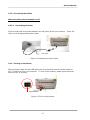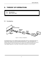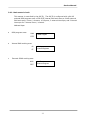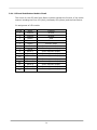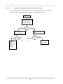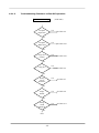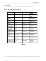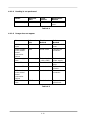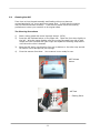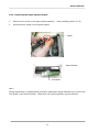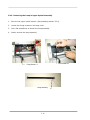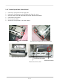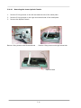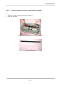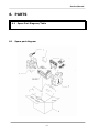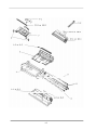
1
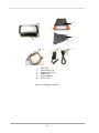
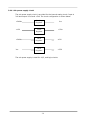
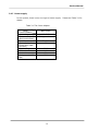
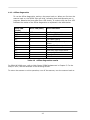
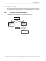
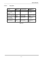
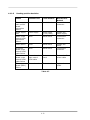
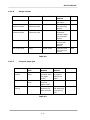
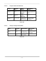
Sheetfed Scanner
Service Manual
Version 1.0
Sheetfed Scanner
Contents
1.
INTRODUCTION........................................................................................................................... 1-1
1.1
1.2
1.3
2.
UNPACKING, INSTALLATION, AND TRANSPORTATION.............................................. 2-1
2.1
2.2
2.3
2.4
3.
INTRODUCTION ........................................................................................................................ 3-1
MAIN CONTROL UNIT................................................................................................................ 3-2
3.2.1 System diagram.................................................................................................... 3-2
3.2.2 Main control circuit............................................................................................... 3-3
3.2.3 Video circuit: ......................................................................................................... 3-4
3.2.4 LED and Push Button Module Circuit................................................................ 3-6
3.2.5 Sensor input .......................................................................................................... 3-7
3.2.6 Sub power supply circuit..................................................................................... 3-8
3.2.7 Power supply ......................................................................................................... 3-9
PROBLEM SOLVING.................................................................................................................... 4-1
4.1
4.2
5.
PRECAUTIONS OF INSTALLATION .............................................................................................. 2-1
UNPACKING PROCEDURE .......................................................................................................... 2-1
INSTALLATION ......................................................................................................................... 2-3
2.3.1 Installing the ADF Paper Tray............................................................................ 2-3
2.3.2 Installing the ADF Output Paper Tray .............................................................. 2-4
2.3.3 Connecting the Cables......................................................................................... 2-5
2.3.4 Turning on the Power .......................................................................................... 2-5
PLACING THE ORIGINAL ........................................................................................................... 2-6
THEORY OF OPERATION .......................................................................................................... 3-1
3.1
3.2
4.
GENERAL NOTES FOR SERVICING.............................................................................................. 1-1
GENERAL DESCRIPTION ........................................................................................................... 1-2
BASIC SPECIFICATIONS ........................................................................................................... 1-2
DIAGNOSTICS .......................................................................................................................... 4-1
4.1.1 Online diagnostics ................................................................................................ 4-1
4.1.2 Offline diagnostics ................................................................................................ 4-2
4.1.3 Diagnostic flowcharts........................................................................................... 4-3
TROUBLESHOOTING ................................................................................................................. 4-6
4.2.1 Flowcharts .............................................................................................................. 4-6
4.2.2 Tables...................................................................................................................... 4-9
DISASSEMBLY .............................................................................................................................. 5-1
5.1
5.2
5.3
5.4
SERVICE TOOL......................................................................................................................... 5-1
CLEANING THE ADF ................................................................................................................ 5-2
CLEANING THE CALIBRATION AREA .......................................................................................... 5-3
PROCEDURE FOR DISASSEMBLY AND REASSEMBLY .................................................................... 5-4
5.4.1 Notes on disassembly.......................................................................................... 5-4
5.4.2 Removing the Upper Housing ............................................................................ 5-5
5.4.3 Removing the Upper Optical Assembly............................................................ 5-7
5.4.4 Removing the Upper Optical Chassis ............................................................... 5-9
5.4.5 Removing the Lamp in Upper Optical Assembly.......................................... 5-10
ii
Service Manual
5.4.6
5.4.7
5.4.8
5.4.9
5.4.10
6.
Removing the ADF Pad...................................................................................... 5-11
Removing the Main Control Board .................................................................. 5-12
Removing the Motor in Lower Optical Assembly ......................................... 5-14
Removing the Inverter in the Lower Optical Assembly.............................. 5-15
Removing the Lower Optical Chassis.......................................................... 5-16
PARTS.............................................................................................................................................. 6-1
6.1
SPARE PART DIAGRAM .............................................................................................................. 6-1
iii
Service Manual
1. INTRODUCTION
1.1 General Notes for Servicing
1.2 General Description
This manual is intended to be used by the maintenance engineers. It describes areas to be
maintained, the detailed installation, the disassembly of optional ADF, and the component
replacement procedures as well as the main trouble shooting guides.
Please take your time to read this manual thoroughly to obtain comprehensive knowledge
about the scanner before serving the unit.
1.1
General notes for servicing
(1)
Before trying to disassemble the scanner, make sure the power supply cord of
theAV220 is disconnected from the power outlet. Under any circumstance, do not
remove or install the connectors on the scanner with the power supply turned ON.
(2)
Use caution not to drop small parts or screws inside the unit when disassembling and
reassembling. If left inside, they might cause the malfunction of the unit.
(3)
Do not pull the connector cable when disconnecting it.
(4)
When carrying the scanning head unit, put it in an anti-static bag.
(5)
Keep the document table glass surface always clean.
clean cloth for cleaning.
(6)
Use caution not to injure your fingers or hands when disassembling or reassembling
the unit.
1-1
Hold the connector.
If contaminated, use a dry
Sheetfed Scanner
1.2
General Description
The scanner which features small footprint and fast scan rate is the perfect companion at
your desktop. The build-in automatic document feeder allows 50 sheets of documents to be
scanned continuously at one time and achieves fast scan rate of 25 pages per minute in
simplex mode and 50 images per minute in duplex mode.
1.3
Basic Specifications
Type:
Sheetfed scanner, duplex
Optical Resolution:
600 dpi
Color Depth:
48-bit Color (input)
24-bit Color (output) single pass color (R, G, B)
256 shades of gray scale
64 shades of gray for halftones
Line art (binary)
Error diffusion
8-bit Color
24-bit Color
25 pages per minute (simplex mode)
50 images per minute (duplex mode)
Image Type:
ADF Scan Speed:
(NONE Channel at 200dpi
B&W A4 size)
Scan Area:
ADF: minimum: 3.5” x 2” (88 x 50 mm)
ADF: maximum: 8.5”x 14” (215 x 355 mm)
Paper Size:
ADF Max.: 8.5” x 14” (Legal)
ADF single page min.: 3.5” x 2”
ADF duplex multipage min.: 3.5” x 3.0”
Paper Thickness:
16 – 28 lbs/0.002” ~ 0.006”
Paper Input (ADF):
up to 50 sheets
Physical Dimension:
HxWxD
Weight:
Interface:
6.37 x 13,2 x 6.5 inches (without tray)
(162.3 x 337.2 x 167.8 mm)
4.3 kg
USB 2.0
Power Source:
Input: 100~240V, AC, 50/60 Hz
Output: 24V, DC, 2.0A
≤ 30 Watts
Power Consumption:
1-2
Service Manual
2. UNPACKING, INSTALLATION, AND
TRANSPORTATION
2.1
2.2
2.3
2.4
2.5
2.1
Precautions of Installation
Unpacking Procedure
Installation
Placing the Original
Transportation
Precautions of Installation
Pay attention to the following matters before unpacking and installation.
•
•
•
•
•
•
•
•
2.2
Do not install in a place where vibration may occur.
Keep the scanner out of direct sunlight. Do not install near a heat source.
Do not place the scanner around materials which shut off the circulation of air.
Do not install in a humid or dusty place.
Use care not to scratch the glass surface of the scanner or the document holding
pad with a clip or staple.
Do not use the wall socket with connecting devices which may generate noise, for
example, air-conditioner, etc.
Use a suitable AC power source.
Place the scanner on a level surface.
Unpacking Procedure
Unpack the scanner according to the following procedure.
•
•
•
•
•
Remove the packing material.
Remove the scanner from the shipping container.
Remove the scanner from the PVC bag.
Check the items by referring to Figure 2.1.
For any missing items, please contact your nearest dealer or distributor.
Note:
Keep all the packing material in case you may need to return the scanner.
2-1
2
3
1
4
1.
2.
3.
4.
5.
6.
5
Main Unit
Input Paper Tray
Output Paper Tray
USB Cable
Power Adapter
Power Cord
Figure 2.1 Package Contents
2-2
6
Service Manual
2.3
Installation
2.3.1 Installing the ADF Paper Tray
1.
Attach the ADF Paper Tray to the clip joint of the scanner as indicated below.
properly insert, you will hear a snap-in sound.
ADF Input
Paper Tray
Scanner
Clip Joint
Figure 2.2 Installing the ADF Paper Tray
2-3
When
2.3.2 Installing the ADF Output Paper Tray
1.
Hold the Output paper tray some 30 degrees as shown in below.
2.
Insert the right protrusion of the Output Paper Tray into the hole on the front of the
scanner.
3.
Insert the left protrusion of the Output Paper Tray slightly into the hole on the front of
the scanner.
Scanner
Output
Paper Tray
Hole
Output
Paper Tray
Protrusion
Figure 2.3 Installing the Output Paper Tray
2-4
Service Manual
2.3.3 Connecting the Cables
Make sure the power of scanner is off.
2.3.3.1
Connecting to Power
Plug the small end of the power adaptor into the power jack of your scanner.
other end to an appropriate power outlet.
Insert the
Power Cable
Figure 2.4 Installing the Power Cable
2.3.4 Turning on the Power
After the power cable and the USB cable have all connected, press the power switch to
the “I” position to turn on the scanner. To turn off the scanner, please press the power
switch to the “O” position.
Power Switch
Figure 2.5 Turn on the scanner
2-5
2.4
Placing the original
Document feeding
Place your document with the text face down on the ADF Input Paper Tray. Align the
two sides of the document with the slide guides. Please note that the ADF Input Paper
Tray can hold up to 50-page document at a time.
Your
Document
(Face
Do n)
Paper Slider
Figure 2.6 Place the document
2-6
Service Manual
3. THEORY OF OPERATION
3.1
3.2
3.1
Introduction
Main Control Unit
Introduction
Cold
Fluorescent Lamp
Hos
Analogue
Analogu
Signa
Signal
Reflecte
Reflected
Ray
Len
Mai
Main
Boar
Board
CCD
Digital
Digital
Signa
Signal
1 0 0
1 0
Host
USB 2.0
Controller
Figure 3.1 Theory of Operation
The reflected rays of your original as shown in the above Figure 3.1 pass through the lens
and create an image on the CCD (Charged Coupled Device). Then, according to the
different light intensity perceived by the CCD, the CCD will transfer these data into a series
of analog signals to the main board, where the signals are turned into digital signals.
These digital signals flow to the USB 2.0 Controller to transfer to a host computer.
3-1
3.2
Main control unit
3.2.1 System diagram
Figure 3.2
System block diagram
3-2
Service Manual
3.2.2 Main control circuit
This scanner is controlled by the 80C32. The 80C32 is configured with a 64-KB
external ROM program area, a 256-BYTE internal RAM work area, a 64-KB external
RAM work area, 2 timer / counters, 4 I/O ports, 2 external interrupts, and 2 internal
interrupts for 2 internal timer / counters.
Address Maps:
•
ROM program area:
0000
64KB Program
FFFF
•
Internal RAM working area:
00
256-byte
Internal Registers
FF
y
External SRAM working area:
0000
FFFF
64 KB
External Program
3-3
3.2.3
Video circuit:
The video circuit of the scanner includes: 1. CCD driving circuit, 2. CCD signal
processing circuit.
1.
CCD Driving Circuit
The CCD driving circuit is used to generate correct signals to the CCD, so that the
CCD may generate the correct image data.
Signals for CCD:
Pin Assignment for CCD cable
Pin
No.
Name
Function
1
AG
Analog Ground
2
VOR
CCD Red Channel Output Signal
3
AG
Analog Ground
4
VOG
CCD Green Channel Output Signal
5
AG
Analog Ground
6
VOB
CCD Blue Channel Output Signal
7
AG
Analog Ground
8
12VDC
CCD Power Supply
9
SH
CCD RGB Channel Shift Gate
10
PHI1
CCD Clock Phase
11
DG
Digital Ground
12
PHI2
CCD Clock Phase
13
DG
Digital Ground
14
RS
CCD Reset Gate
15
DG
Digital Ground
16
CP
Clamp Gate
17
VCC
Digital 5V Power Supply
18
SW
Changeover Switch (color and
B/W)
3-4
Service Manual
2. CCD signal processing circuit
R
CCD
CDS
PGA
CDS
PGA
CDS
PGA
G
MUX
ADC
Dout
B
CCD Signal Processor
The CCD signal processor includes all the necessary circuitry to perform threechannel conditioning and sampling. The signal chain consists of three-channel
correlated double sampling (CDS) and programmable gain adjustment of the CCD
output (PGA) is a 16 bit analog to digital connector (ADC) quantizes the analog
signal.
3-5
3.2.4 LED and Push Button Module Circuit
The circuit for the LED and Push Button modules showes the function of the entire
scanner including the Error LED (Red), the Ready LED (Green) and the Push Button.
.
Pin assignment of LED module
Pin No.
Name
Function
1
Ground
Ground
2
Ground
Ground
3
Button
Scan
4
Button
Cancel
5
Button
Function select
6
LED G
7
LED R
Ready status indicator
Seven segment display
8
Seven segment display
9
Seven 1
Seven 2
10
Seven 3
Seven segment display
11
Seven 4
Seven segment display
12
Seven 5
Seven segment display
13
Seven 6
Seven segment display
14
Seven 7
Seven segment display
15
Seven 8
Seven segment display
Seven segment display
3-6
Service Manual
3.2.5 Sensor input
A.
Photo_Sensor
The sensor input includes paper in/out sensor.
Paper In/Out sensor
The paper position is detected by photo sensor. The photo transistor transmission
to the photo sensor receiver circuit is shown below.
Out
Figure 3.3 Paper in/out sensor
The paper in/out sensor is detected when the paper passes between the LED and the
photo transistor.
B.
IR-Sensor
+5V
+5V
+
_
-
(OP)
DAC
Figure 3.4 IR_Sensor
3-7
Out
3.2.6 Sub power supply circuit
The sub power supply circuit is provided for the internal analog circuit. Input is
24V and output is Vcc and +5Va. The circuit configuration is shown below:
+24Vdc
Switching
Regulator
Vcc
+12V
Linear
Regulator
+5Va
+24Vdc
Linear
Regulator
+12V
Vcc
Linear
Regulator
+3.3V
The sub power supply is used for: A/D, and logic circuits.
3-8
Service Manual
3.2.7 Power supply
In this system, there is only one type of power supply.
details.
Table 3.1 The Power Adapter
Type
Characteristic
Input voltage range
Input current (at the
rated input/output)
Input frequency
Max. in-rush
current(@full load,
cold start)
Output voltage
Min. load current
Max. load current
Total power (at full
load)
Wall-mount
100-240V
2A type or less
50-60Hz
45A
+24Vdc
0.0A
2A
30W
3-9
Please see Table 3.1 for
Service Manual
4. PROBLEM SOLVING
4.1
4.2
Diagnostics
Troubleshooting
This chapter supplies two paths for dealing with operational problems. The first relies
on the scanner’s internal diagnostics. The second uses troubleshooting flowcharts and
tables to isolate the problem. In many cases, the internal diagnostics will help you to
locate the source of the problem quickly. Use these diagnostics first. If the
diagnostics do not locate the source of the problem, refer to Section 4.2
Troubleshooting.
4.1
Diagnostics
The scanner has internal diagnostics to help you determine the cause of operational
problems. Some of the diagnostics function with the scanner online, while others are
part of a separate offline diagnostics feature.
4.1.1 Online diagnostics
Determine operational problems by observing the display panel Error, Ready, and
Check LEDs. With the scanner online and operating normally, the Ready LED is on
and the Error LED is off. Any other Error LED indicates a problem, as shown in the
following table.
Ready LED
Check LED
Error LED
Indication
Table 4.1
Green LED On
Green LED Blinking
RED LED Blinking
(Group Error)
Online diagnostics
If the ADF cover is open, close it. For the group errors, see the flowcharts later in this
section.
4-1
4.1.2 Offline diagnostics
To run the offline diagnostics, and turn the power back on. When you first turn the
scanner back on, the READY light will blink, indicating that the diagnostics are in
progress. Observe the front panel Error LED closely. In a short time, the Error LED
indicates the results of the offline diagnostics as explained in the table below.
Ready LED
(Green)
ON (No blinking)
OFF
OFF
OFF
OFF
Error LED (RED)
Error Indication
OFF
1
2
3
4
OFF
OFF
OFF
OFF
OFF
OFF
5
6
7
8
9
0
OK (Ready)
Face down SDRAM failure
Face up DRAM failure
CPU DRAM failure
Face down DC offset adjust
failure
Face up DC offset adjust failure
Cover open error
Face down light check failure
Face up light check failure
Paper jam
USB disconnect
Table 4.2
Offline diagnostics results
For SRAM & DRAM error, refer to Main Control PCBA Replacement in Chapter 5. For the
Group 2 error, see the flowchart in the following section.
To return the scanner to online operation, turn off the scanner, turn the scanner back on.
4-2
Service Manual
4.1.3 Diagnostic flowcharts
Use the flowcharts that follow to determine the exact problem when either the online
or offline diagnostics indicate a group error. Refer to Chapter 4 for parts replacement.
4.1.3.1
Group 1 error flowchart (CCFL assembly)
This flowchart applies when the Error LED shows number 7 and 8.
Group 1 Error
Yes
No
CCFL is on?
CCD error
Replace optical
assembly
Inverter error
Replace lamp
inverter circuit
End of test
Yes
CCFL is on?
No
Replace the CCFL
4-3
4.1.3.2
Group 2 error flowchart (paper in ADF paper tray)
This flowchart applies when the Ready LED is off and Error LED shows number 9
with the scanner online, and there is paper in the ADF paper tray.
Group 2 error
Open cover and then
remove the papers from
ADF’s input paper tray,
and wait for 3 seconds
than close the cover.
Yes
ADF
motor
moves?
No
ADF paper-in sensor error
Replace ADF paper-in
sensor or SB12 PCBA
Yes
IR-sensor
error
Replace IR
sensor or
SB12
PCBA
Try again,
ADF motor
moves?
Place paper in the ADF
paper tray and wait for 3
seconds
Yes
No
OK
ADF motor
moves?
No
IR-sensor error or
scanner inside
contains paper
OK
4-4
Service Manual
4.1.3.3
Group 3 error flowchart (no paper in ADF paper tray)
This flowchart applies when the Ready LED is off and Error LED shows number 6
with the scanner online, and there is no paper in the ADF paper tray.
Group 3 Error
Open cover, then close the
cover
Yes
No
Check Ready LED on?
OK
Refer to the
Result in Table
3.2
Place a piece of paper
into ADF Input Paper
Tray and waits for 3 secs.
4-5
4.2
Troubleshooting
Refer first to the applicable troubleshooting flowchart in the following three sections.
The flowcharts refer you to the appropriate table for detailed troubleshooting.
4.2.1 Flowcharts
This section provides the following troubleshooting flowcharts:
•
•
Troubleshooting from power on to scanner ready
Online troubleshooting (ADF operation)
4-6
Service Manual
4.2.1.1
Troubleshooting flowchart: power on to scanner ready.
Troubleshooting From Power on
No
Power
LED on
Yes
Cover open test
IR sensor test
DRAM Test
Face down SDRAM test
Face up SDRAM test
Face down light check
Face up light check
Warming-up Check
(Green LED Blinking)
Warmingup Finish?
Yes
Wait for command
from host
(Green LED on)
4-7
No
See Table 4.3
4.2.1.2
Troubleshooting flowchart: online ADF operation
Online Troubleshooting
(ADF mode)
Yes
Frequent
Paper Jam?
See Table 4.9
No
Yes
Frequent
double feed
See Table 4.10
No
Yes
Large skew
volume?
See Table 4.10
No
Yes
Large jitter
See Table 4.6
No
Reading
position
Yes
See Table 4.7
deviation?
No
Image
unclear
Yes
See Table 4.8
Yes
See Table 4.11
No
Strange
sound
generated?
No
End
4-8
Service Manual
4.2.2 Tables
The tables in this section provide detailed troubleshooting information.
4.2.2.1
The Power LED does not go on
Cause
Relevant Unit
Check Method
Maintenance
Method
Unplugged from
outlet
None
Visual check
AC power
unplugged at
unit
Power switch is
OFF
AC voltage
failure
Power unit AC
input connector
disconnected
Power switch
connector
disconnected
Power unit-main
PCBA connection
failure
Power unit
output voltage
failure
PCBA Failure
None
Visual check
Insert the AC
plug into the
outlet.
Insert the AC
cable into unit.
None
Visual check
None
None
AC outlet voltage
check
Visual check
None
Visual check
Connect the
connector.
None
Visual check
Connect the
connector.
Power unit
Output voltage
(+24V) check
Replace the
power unit
Main control
PCBA
LED board
None
Tester check
(+24V, GND)
Remove the
cause or replace
the PCBA.
Visual check
Connect the
connector
LED board-main
PCBA connection
failure
Table 4.3
4-9
Turn the power
switch on.
None
Connect the
connector.
4.2.2.2
Reading is not performed
Cause
Relevant
Unit
Check
Method
Maintenance
Method
ADF cover open
ADF cover
Visual check
Close the ADF
cover.
Table 4.4
4.2.2.3
Image does not appear
Cause
Relevant
Unit
Check
Method
Maintenance
Method
ADF cover
open
Power supplymain control
board
connection
failure
Power supply
fails.
Lamp failure
ADF cover
Visual check
None
Visual check
Close the ADF
cover
Connect the
connector.
Power supply
Lamp
Tester check
(+24V, GND)
Visual check
Inverter failure
Inverter
Visual check
CCD boardmain control
board
connection
failure
CCD board
fails.
None
Visual check
CCD Board
Visual check
Table 4.5
4-10
Replace the
power supply.
Replace the
lamp.
Replace the
inverter.
Connect the
connector.
Replace the
optical unit.
Service Manual
4.2.2.4
Large jitter
Cause
Relevant
Unit
Check Method
Maintenance
Method
Power supplymain control
board connection
failure
Power supply fails
None
Visual check
Connect the
connector.
Power
supply
None
Tester check
(+24V, GND)
Visual check
Replace the power
supply.
Connect the
connector.
Motor
Visual check
Replace the
motor.
Motor-main
control PCBA
connection failure
Motor failure
Table 4.6
4-11
4.2.2.5
Reading position deviation
Cause
Relevant Unit
Check Method
Maintenance
Method
Power supplymain control
board
connection
failure
Power supply
fails
Motor- main
control PCBA
connection
failure
Motor failure
None
Visual check
Connect the
connector.
Power supply
None
Tester check
(+24V, GND)
Visual check
Replace the
power supply.
Connect the
connector.
Motor
Visual check
IR sensor
board- main
control PCBA
cable failure
IR sensor
board- main
control PCBA
cable failure
IR sensor
board (SB21)
failure
None
Visual check
Replace the
motor
Connect the
connector
Sensor boardmain control
PCBA cable
Tester or visual
check
Replace the IR
sensor cable
Sensor board
Tester check
Replace the
PCBA.
Table 4.7
4-12
Service Manual
4.2.2.6
Image unclear
Cause
Relevant Unit
Check Method
Maintenance
Method
Remar
k
Lamp too dark
Lamp
Visual check
None
Dirt on calibration
reference plate
Calibration
reference plate
Visual check
Dirt on calibration
reference plate
Calibration
reference plate
Visual check
Dirt on the mirrors
Mirrors
Visual check
Dirt on the lens
Lens
Visual check
Replace with a
new lamp.
Clean the glass
with isopropyl
alcohol.
Clean the
calibration
reference plate
with isopropyl
alcohol.
Clean the
mirrors with
isopropyl
alcohol.
Clean the lens
with isopropyl
alcohol.
None
None
None
None
Table 4.8
4.2.2.7
Frequent paper jam
Cause
Relevant
Unit
Check
Method
Maintenance
Method
Remark
Paper setting
failure
Operation
error
operation
error
Educate users
to properly
position the
paper.
None
None
Paper failure
Pad assembly
failure
Pad assembly
Is the paper
correctly set in
the paper
chute?
Is the
specified
paper used?
Check the pad
assembly for
wear and tear
Replace the
pad assembly/
touch spring
unit.
None
Table 4.9
4-13
None
4.2.2.8
Frequent double feed and skew
Cause
Relevant
Unit
Check
Method
Maintenance
Method
Paper setting
failure
Operation
error
Teach users to
properly position the
paper
Paper failure
Operation
error
Pad assembly
failure
Pad assembly
Is the paper
correctly set in
the paper
chute?
Is the
specified
paper used
Check the pad
assembly for
wear and tear.
None
Replace the pad
assembly/ touch
spring unit.
Table 4.10
4.2.2.9
Strange sound generated (ADF)
Cause
Relevant
Unit
Check Method
Maintenance
Method
Paper setting
failure
Operation
error
paper failure
Operation
error
Is the paper
correctly set in
the paper chute?
Is the specified
paper used?
Teach users to
properly position
the paper
None
Table 4.11
4-14
Service Manual
5. DISASSEMBLY
5.1
5.2
5.3
Service Tools
Lubricants
Procedure for Disassembly and Reassembly
5.1
Service Tool
Table 5.1 describes the maintenance tools necessary for the maintenance of this
equipment.
No
.
Name
Description
1
2
Minus screwdriver
Philips screwdriver
(magnetic)
Oil
Grease
Alcohol (Isopropyl 91% >)
Digital voltmeter
Oscilloscope
Idler pulley module screw
Nominal No.2 M3, M4
3
4
5
6
7
Table 5.1
Shell “Terrace Oil 46”
Shell “Alvania Grease No.2”
Cleaning
With 0.01 V range
100 MHz or more with
external sweep
Maintenance tools
5-1
5.2
Cleaning the ADF
From time to time the pad assembly and feeding rollers may become
contaminated with ink, toner particles or paper dust. In this case the scanner
may not feed documents smoothly. If this occurs please follow the cleaning
procedures to return your machine to its original state.
The Cleaning Procedures
1)
Soak a cotton swab with some isopropyl alcohol. (95%).
2)
Press the ADF Release button on the upper-left. Open the front door slightly to
the left. Wipe the upper feeding roller by moving the swab from side to side.
Rotate the roller forward with your finger and repeat the cleaning steps above
until the entire roller is cleaned.
3)
Wipe the ADF pad in one direction from top to bottom or the other way around.
Be careful not to damage the pick springs.
4)
Close the scanner front door.
Your scanner is now ready for use.
ADF Release
button
ADF Pad
Feeding Roller
5-2
Service Manual
5.3
1.
2.
3.
Cleaning the Calibration Area
Press the Paper Jam Clearing button. Open the front door to the left.
Wet a cotton swab with some isopropyl alcohol. (95%)
Wipe the glass and the white area as illustrated in below by moving the swab from side
to side to rid the dust or dirt.
Calibration
Area
Glass
ADF Front Door
5-3
5.4
Procedure for disassembly and reassembly
5.4.1 Notes on disassembly
(1)
Clean the disassembly and assembly location.
(2)
Disconnect the power cable and remove the AC plug from the outlet before
disassembly and assembly.
(3)
Follow the disassembly and assembly procedures. Never loosen the screws of
parts that must not be disassembled.
(4)
Store the disassembled parts in a clean place to avoid loss.
(5)
After replacement, check the contacts and spare part mounting.
(6)
Assemble the parts in reverse order of disassembly procedure.
5-4
Service Manual
5.4.2 Removing the Upper Housing
1.
Hold the Output Paper Tray and push your finger inwardly to remove the Output Paper
Tray.
2.
Hold the Input Paper Tray and lift the Tray to remove it.
3.
Press the ADF release button to open the cover.
4.
Remove 2 fixing screws.
5.
Unscrew the 4 fixing screws on the upper housing.
6.
Remove the Upper Housing.
Press inwardly to remove
the Output Paper Tray
Remove Input Paper Tray
Press the ADF release button
Remove 2 fixing screws
5-5
Remove 4 fixing screws
Remove the upper housing
5-6
Service Manual
5.4.3 Removing the Upper Optical Assembly
1.
Press the Paper Jam Release Button to open the cover.
2.
Loosen 2 fixing screws on the upper case.
3.
4.
5.
Remove the fixing sponge.
Loosen 2 fixing screws on the left side.
Loosen 1 fixing screw on the right side.
Paper Jam
Released Button
Fixing Screw x 2
Sponge
Fixing screws x 2
5-7
6.
Disconnect the inverter cable with red and black colors.
7.
Disconnect the lamp inverter cable (in white color) to remove the inverter.
Fixing Screw x 1
Inverter Cable
Power cable
Inverter
5-8
Service Manual
5.4.4 Removing the Upper Optical Chassis
1.
Remove the inverter in the upper optical assembly.
2.
Disconnect two cables on the optical chassis.
(See preceding section 5.3.3)
Cables
Optical Chassis
CCD Board
Note:
During assembling or disassembling procedure, please pay special attention not to touch the
CCD board on the optical chassis. Otherwise, the scanning quality may be affected.
5-9
5.4.5 Removing the Lamp in Upper Optical Assembly
1.
Remove the upper optical chassis. (See preceding section 5.3.4)
2.
Loosen two fixing screws on the lamp cover.
3.
Use a flat screwdriver to loosen the lamp assembly.
4.
Gently remove the lamp assembly.
Flat screwdriver
Fixing Screw x 2
Lamp assembly
5-10
Service Manual
5.4.6 Removing the ADF Pad
Use your fingers to press two sides of the ADF pad and lift the pad on the upper optical
assembly to remove it.
ADF Pad
5-11
5.4.7 Removing the Main Control Board
1.
Unscrew 1 fixing screw on the right side.
2.
Unscrew 2 fixing screws on the left side and close the cover.
3.
Raise the main unit and disconnect the motor cable and flat cable.
4.
Unscrew all fixing screw.
5.
Disconnect all cables.
6.
Remove 4 fixing screws on the main board.
Remove one fixing screw on the right
side
Remove two fixing screws on the left side
Raise the main unit a bit
Disconnect flat cable
Disconnect motor cable
5-12
Disconnect cables
Service Manual
Power cable
2 Fixing
screw
2 fixing
screw
Remove 4 fixing screw and disconnect the power cable
The main board
5-13
5.4.8 Removing the Motor in Lower Optical Assembly
1.
Turn the scanner over.
2.
Remove 2 fixing screws on the external side of the metal plate.
3.
Remove the motor.
Remove 2 fixing screws
The motor
5-14
Service Manual
5.4.9 Removing the Inverter in the Lower Optical Assembly
1.
Cut the cable bondage.
2.
Remove the inverter from the plastic fixing plate.
3.
Disconnect the inverter cable.
Inverter
The inverter
cable
Release the inverter from the plastic plate and disconnect the inverter cable
The inverter
5-15
5.4.10
Removing the Lower Optical Chassis
1.
Remove 2 fixing screws on the left and external side of the metal plate.
2.
Remove 2 fixing screws on the right and internal side of the metal plate.
3.
Remove the Optical Chassis.
Remove 2 fixing screws on the left external side
Remove 2 fixing screws on the right internal side
Optical Chassis
5-16
Service Manual
5.4.11
Removing the Lamp in the Lower Optical Assembly
1.
Remove 2 fixing screws on the lamp assembly.
2.
Remove the lamp.
Remove 2 fixing screws on the lamp assembly
The lamp assembly
5-17
Service Manual
6. PARTS
6.1
6.1
Spare Part Diagram/Table
Spare part diagram
6-1
6-2
Service Manual
6-3
Xerox DocuMate 252 Spare Parts List:
XEROX DocuMate 252
SERVICE PARTS TABLE
VISIONEER P/N
65-0247-000
65-0295-000
65-0296-000
65-0248-000
65-0249-000
65-0250-000
65-0251-000
65-0242-000
65-0297-000
65-0298-000
65-0248-000
65-0252-000
65-0253-000
65-0299-000
65-0300-000
65-0254-000
65-0255-000
65-0256-000
65-0302-000
65-0303-000
65-0304-000
65-0305-000
57-0104-000
57-0105-000
65-0306-000
65-0307-000
65-0308-000
65-0258-000
65-0310-000
65-0311-000
65-0312-000
ACCESSORIES
65-0313-000
65-0314-000
65-0259-000
35-0071-000
65-0497-000
65-0498-000
65-0499-000
65-0500-000
65-0501-000
65-0502-000
DESCRIPTION
OPTICAL, LOWER, W/LAMP
ASS'Y, LOWER OPTICAL: FOR FACE-DOWN
ASS'Y, LAMP MOUNT, FACE DOWN
INVERTER
ROLLER, FEED, PAPER IN
ASS'Y, MOTOR
ASS'Y, PAPER PATH LOWER
OPTICAL, FACE DOWN, W/LAMP, GREEN CCD
ASS'Y, OPTICAL, FACE DOWN, TRANSTION
ASS'Y, LAMP, FACE DOWN
INVERTER, 24VDC
ASS'Y, PAPER GUIDE, UPPER, W/O LAMP
PCBA, LB47
CABLE: 2/2 HOUSING,
CABLE: 12P
ROLLER, FEED, PAPER OUT
BEARING COVER HINGE
HOUSING, BOTTOM
PCBA
POWER S/W 5 pin
ASS'Y, COVER UNIT
ASS'Y, UPPER HOUSING
ASS'Y, ADF INPUT TRAY / DM252
ASS'Y, PAPER OUTPUT TRAY / DM252
OPTICAL, UPPER, W/LAMP
ASS'Y, OPTICAL, UPPER
ASS'Y, LAMP MOUNT, FACE UP
INVERTER (CCFL-T)
OPTICAL, FACE UP, W/LAMP, GREEN CCD
ASS'Y, OPTICAL, FACE UP, TRANSITION
ASS'Y, LAMP
EPS FOAM, L: 310x278x160
EPS FOAM, R: 310x278x160
ADAPTOR, WITH EMI CORE
AC POWER CORD, UL/CSA, PLUG
AC POWER CORD: EUR
AC POWER CORD: UK
USB 2.0 CABLE
S/W PACKAGE
S/W PACKAGE: EUR/UK (EFIGS)
CARTON: 470x290x340, A/F
Xerox DocuMate 262 Spare Parts List:
XEROX DocuMate 262 GREEN
SERVICE PARTS TABLE
VISIONEER P/N
DESCRIPTION
65-0372-000
65-0322-000
S-PARTS: ASS'Y, PAPER GUIDE, UPPER W/O LAMP, RoHS
S-PARTS: PCBA: LBA69, RoHS
S-PARTS: CABLE: 2/2 HOUSING, 14P+6P, P=2.0mm, L=420mm,
28AWG,聯 穎, W/TUBE, W/CORE, RoHS
S-PARTS: CABLE: 2 HOUSING, 12P/12P, P=2.0mm, L=420mm, 28AWG,
1500.002147.00, 聯穎, W/TUBE, RoHS
S-PARTS: PCBA: SBA45, IR Sensor Board, RoHS
S-PARTS: PCBA: SBA51, RoHS
S-PARTS: ASS'Y,SENSOR:SG-413JAV01,3P,P=2.0mm,L=120mm,RoHS
S-PARTS:SHEET,CALIBRATION,UPPER,230X6.5X0.3T,MELINEX
329,210,(5PCS),RoHS
S-PARTS: BEARING COVER HINGE, OD=13, ID=10, POM, WHITE, RoHS
S-PARTS: Screw & Damper, For Optical module, (1SET=10PCS), RoHS
S-PARTS: ASS'Y, OPTICAL, FACE UP, W/LAMP(002-3087-0),
W/INVERTER(005-0021-09), RoHS
S-PARTS: ASS'Y, OPTICAL, FACE UP, RoHS
S-PARTS: ASS'Y, LAMP, FACE UP, RoHS
S-PARTS: INVERTER: 24V, 6mA, 35KHz, XAD355SR-1, TDK, RoHS
S-PARTS: ASS'Y, OPTICAL, FACE DOWN, W/LAMP( 002-3343-0),
W/INVERTER (005-0022-09), RoHS
S-PARTS: ASS'Y, OPTICAL, FACE DOWN, RoHS
S-PARTS: ASS'Y, LAMP, FACE DOWN, RoHS
S-PARTS: INVERTER:24V,6mA,35KHz,XAD3552,TDK,WIRE:200mm,RoHS
S-PARTS: ASS'Y, PAPER GUIDE, LOWER,W/O LAMP(002-3343-0),RoHS
S-PARTS: BELT, 58T, MXL, W=4.8, (10PCS), RoHS
S-PARTS: ASS'Y, MOTOR, RoHS
S-PARTS: ASS'Y, RELEASE HOOK, RoHS
S-PARTS: ASS'Y, ADF ROLLER, RoHS
S-PARTS: ROLLER, FEED, PAPER OUT, φ14.5, EPDM, 298.5, RoHS
S-PARTS: BELT, 65T, MXL, W=4.8, (10PCS), RoHS
S-PARTS: ROLLER, FEED, PAPER IN, φ14.5, EPDM, 316.25, RoHS
S-PARTS: IDLE ROLLER, φ10.4x16, (8 PCS), RoHS
S-PARTS: BELT, 68T, MXL, W=4.8, (10PCS), RoHS
S-PARTS: IDLE PULLEY, 11x25, POM+鐵氟龍, (1SET=10PCS), RoHS
S-PARTS: MOUNT, IDLE SECC, (1SET=10PCS), RoHS
S-PARTS: ASS'Y, COVER TOP UNIT, RoHS
S-PARTS: ASS'Y, ADF INPUT TRAY
S-PARTS: ASS'Y, UPPER HOUSING, RoHS
S-PARTS: FFC CABLE:18P, P=1.0mm, L=160mm, FF-18-1.0-C-160D(4/4/8/8)AA,今皓, 兩端導體不同面, RoHS, (5 PCS)
S-PARTS: PCBA, MB325 WITH FW (259-0147-1), RoHS
65-0299-000
65-0324-000
65-0377-000
65-0326-000
65-0328-000
65-0380-000
65-0255-000
65-0331-000
65-0332-000
65-0384-000
65-0312-000
65-0335-000
65-0336-000
65-0337-000
65-0398-000
65-0339-000
65-0340-000
65-0341-000
65-0250-000
65-0343-000
65-0395-000
65-0254-000
65-0347-000
65-0249-000
65-0349-000
65-0350-000
65-0351-000
65-0352-000
65-0404-000
65-0258-000
65-0305-000
65-0356-000
65-0408-000
65-0256-000
65-0359-000
57-0105-000
ACCESSORIES
65-0094-000
65-0413-000
65-0365-000
65-0182-000
65-0097-000
65-0183-000
65-0369-000
65-0370-000
65-0420-000
S-PARTS: HOUSING, BOTTOM, ABS, 2.5t,337x168x100, SILVER, RoHS
S-PARTS: ASS'Y, POWER S/W: GF037RA-090,驊 陞, 5P, P=2.5mm,
L=50mm, W/TUBE, RoHS
S-PARTS: ASS'Y, PAPER OUTPUT TRAY
S-PARTS: ADAPTER:DESK-TOP,IEC 320-C6,3P,100~240Vac,4Vdc,
2A,48W,HEG42-240200-7L(A)LF, HITRON(海昌),CLASS I, ENER, RoHS
S/W PACKAGE,RoHS
S-PARTS: USB CABLE: USB A(M)/B(M), 4P, L=1850mm, UL2725
28AWG, SV-0411016, 昇文, COLOR:透明, W/CORE, RoHS
S-PARTS: AC POWER CORD, EUR.(CEE), 2P+G. BASE, 16A/250V,
L=1800mm, 3C*0.75mm2, BLACK,良維, PG8B9CIJG0A-05B, RoHS
S-PARTS: AC POWER CORD: US, 3P, 10A/125V, L=1800mm,
3C*18AWG, BLACK,良 維, PH8B2EDJF0A-05B, RoHS
S-PARTS: AC POWER CORD, UK (BS/PSB),3 P, 3A/250V, L=1800mm,
3C*0.75mm2, BLACK,良 維, PG8B9X3JG0A-05B, RoHS
FOAM, EPS, L:310x278x160,發泡倍率:62.5,白色, RoHS
FOAM, EPS, R:310x278x160,發泡倍率: 62.5,白色, RoHS
CARTON: 470x290x340, A/F, RoHS
Xerox DocuMate 272 Spare Parts List:
XEROX DocuMate 272 GREEN
SERVICE PARTS TABLE
VISIONEER
P/N
DESCRIPTION
65-0320-000
65-0322-000
S-PARTS: ASS'Y, PAPER GUIDE, UPPER, W/O LAMP (002-3087-0), RoHS
S-PARTS: PCBA: LBA69, RoHS
65-0299-000
65-0324-000
65-0325-000
65-0326-000
S-PARTS: CABLE: 2/2 HOUSING, 14P+6P, P=2.0mm, L=420mm, 28AWG,聯
65-0327-000
65-0328-000
65-0380-000
65-0255-000
65-0331-000
65-0332-000
65-0333-000
65-0312-000
65-0335-000
65-0336-000
65-0337-000
65-0298-000
68-0339-000
65-340-000
65-0341-000
65-0250-000
65-0343-000
65-0395-000
65-0254-000
65-0347-000
65-0249-000
65-0349-000
65-0350-000
65-0351-000
65-0352-000
65-0353-000
57-0104-000
65-0305-000
65-0356-000
65-0357-000
65-0358-000
65-0359-000
57-0105-000
65-0361-000
S-PARTS: CABLE:2 HOUSING, 12P/12P
S-PARTS: PCBA:SBA45, IR Sensor Board,RoHS
S-PARTS: PCBA: SBA51, RoHS
PARTS: CABLE: 3P/4P, P=2.0mm, L=730mm, 28AWG, T105005020503, TC&C,
W/TUBE
S-PARTS: ASS'Y,SENSOR:SG-413JAV01,勁昇,3P,P=2.0mm,L=120mm,RoHS
S-PARTS:
S-PARTS:
S-PARTS:
S-PARTS:
S-PARTS:
S-PARTS:
S-PARTS:
S-PARTS:
S-PARTS:
S-PARTS:
S-PARTS:
S-PARTS:
S-PARTS:
S-PARTS:
S-PARTS:
S-PARTS:
S-PARTS:
S-PARTS:
S-PARTS:
S-PARTS:
S-PARTS:
S-PARTS:
SHEET,CALIBRATION,UPPER,230X6.5X0.3T,MELINEX 329,210
BEARING COVER HINGE, OD=13, ID=10, POM, WHITE, RoHS
Screw & Damper, For Optical module, (1SET=10PCS), RoHS
ASS'Y, OPTICAL, FACE UP,W/LAMP (002-3087-0),W/INVERTER
ASS'Y, OPTICAL, FACE UP, RoHS
ASS'Y, LAMP, FACE UP, RoHS
INVERTER: 24V, 6mA, 35KHz, XAD355SR-1, TDK, RoHS
ASS'Y,OPTICAL,FACE DOWN,W/LAMP(002-3343-0)w/INVERTER
ASS'Y, OPTICAL, FACE DOWN, RoHS
ASS'Y, LAMP, FACE DOWN, RoHS
INVERTER: 24V,6mA,35KHz,XAD355-2,TDK,WIRE:200mm,RoHS
ASS'Y, PAPER GUIDE, LOWER, W/O LAMP (002-3343-0), RoHS
BELT, 58T, MXL, W=4.8, (10PCS), RoHS
ASS'Y, MOTOR, RoHS
ASS'Y, RELEASE HOOK, RoHS
ASS'Y, ADF ROLLER, RoHS
ROLLER, FEED, PAPER OUT, φ14.5, EPDM, 298.5, RoHS
BELT, 65T, MXL, W=4.8, (10PCS), RoHS
ROLLER, FEED, PAPER IN, φ14.5, EPDM, 316.25, RoHS
IDLE ROLLER, φ10.4x16, (8 PCS), RoHS
BELT, 68T, MXL, W=4.8, (10PCS), RoHS
IDLE PULLEY, 11x25, POM+鐵氟龍, (1SET=10PCS), RoHS
S-PARTS: MOUNT, IDLE SECC, (1SET=10PCS), RoHS
S-PARTS: ASS'Y, TOP COVER
S-PARTS: ASS'Y, ADF INPUT TRAY
S-PARTS: ASS'Y, UPPER HOUSING, RoHS
S-PARTS: FFC CABLE: 18P, P=1.0mm, L=160mm, FF-18-1.0-C-160-D
(4/4/8/8)AA
S-PARTS: PCBA, MB325 WITH FW (259-0148-1), RoHS
S-PARTS: HOUSING, BOTTOM, ABS, 2.5T, 337x168x100, SILVER
S-PARTS: ASS'Y, POWER S/W: GF037RA-090
S-PARTS: ASS'Y, PAPER OUTPUT TRAY
S-PARTS: ASS'Y, INPUT TRAY, REAR, RoHS
65-0362-000
S-PARTS: PCBA, SBA53, BACK-SENSOR, RoHS
ACCESSORIES
65-0094-000
65-0364-000
65-0365-000
65-0182-000
65-0097-000
65-0183-000
65-0369-000
65-0370-000
65-0371-000
S-PARTS: ADAPTER: DESK-TOP, IEC 320-C6, 3P 100-240VAC, HITRON
S/W PACKAGE, RoHS
S-PARTS: USB CABLE:USB A(M)/B(M),4P,L=1850mm,UL2725 28AWG,SVS-PARTS: AC POWER CORD, EUR.(CEE), 2P+G.
S-PARTS: AC POWER CORD:US,3P,10A/125V,L=1800mm,3C*18AWG,BLK
S-PARTS: AC POWER CORD UK
FOAM, EPS, L:310x278x160,發泡倍率:62.5,白色, RoHS
FOAM, EPS, R:310x278x160,發泡倍率: 62.5,白色, RoHS
CARTON: 470x290x340, A/F, RoHS