1
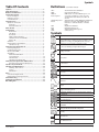
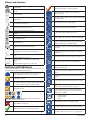
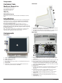
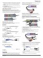
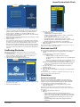
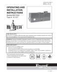
Service Manual
Setup
1. Select Procedure
Monitoring
Reports
Setup
Step 1 of 2
1. Select Procedure
Information
Neuro/Otology
Monitoring
Reports
Step 1 of 2
Information
Neuro/Otology
Head/Neck
Head/Neck
Peripheral
Peripheral
Custom Procedures
Custom Procedures
NIM-Neuro® 3.0
* indicates default settings have been changed
5/1/2009 9:00 AM
NIM-Response® 3.0
?
Global
Settings
Help
GUI vxxxx.x.xxxxx DSP vxxx.x.xx.xxxx
NIM-Neuro®3.0
Instructions For Use
* indicates default settings have been changed
5/1/2009 9:00 AM
NIM-Response® 3.0
?
Global
Settings
Help
GUI vxxxx.x.xxxxx DSP vxxx.x.xx.xxxx
Medtronic Xomed, Inc.
6743 Southpoint Drive North
Jacksonville, FL 32216 USA
www.medtronicENT.com
Help Line
(800)-874-5797
™ are trademarks and ® are registered marks of Medtronic Xomed, Inc.
The information contained in this document was accurate at time of publication. Medtronic reserves the right to make changes in the
product described in this manual without notice and without incorporating those changes in any products already sold.
Symbols
Table Of Contents
Symbols...............................................................................3
Table Of Contents...............................................................3
Buttons and Indicators ......................................................4
System Description.............................................................5
Device Description...........................................................................5
Indications for Use............................................................................5
Contraindications.............................................................................5
Definitions (used in this manual)
APS™
NIM®
NIM 3.0
Event Sequence
Customer Care....................................................................6
Stimulus Rejection
Period
Introduction.......................................................................6
Components.......................................................................6
GUI
DSP
ABR
SSEP
Medtronic Xomed, Inc. ...................................................................6
Help Line.......................................................................................6
International Service...................................................................6
Front Panel....................................................................................6
Side Panel......................................................................................6
Rear Panel.....................................................................................6
NIM 3.0 Patient Interface...........................................................7
Stimulator Probes and Handles..................................................7
Monopolar....................................................................................7
Simulator............................................................................................7
Patient Interface and Simulator.......................................................7
Simulator Set-up:.........................................................................8
Annual System Quick Check..............................................8
Power Up Diagnostics .....................................................................8
Confirming Electrodes.....................................................................9
Electrode Lead Off............................................................................9
Stimulation.........................................................................................9
Mechanical Stimulation..............................................................9
Set and Measure...........................................................................10
Threshold Test..............................................................................10
Simulation Troubleshooting . ....................................................10
Annual System Quick Check Data Sheet...........................11
Preventive and Corrective Maintenance...................................11
Advanced System Check.....................................................12
Cleaning and Maintenance................................................12
Cleaning (after each use) ...........................................................12
Storage...........................................................................................12
Maintenance.................................................................................12
Fuses...................................................................................13
Console Fuse Replacement..............................................................13
Patient Interface Fuse Replacement................................................14
Troubleshooting.................................................................15
Technical Specifications ...................................................17
Block Diagram....................................................................19
Symbols
Automatic Periodic Stimulation.
Nerve Integrity Monitor.
NIM‑Neuro® 3.0 or the NIM-Response® 3.0
A sequence is defined as a series of events
separated from each other by less than one
second.
Adjustable delay reading EMG after stimulation.
In previous versions of the NIM®, this was
referred to as Stimulus Artifact or Artifact
Delay.
Graphic User Interface.
Digital Signal Processor.
Auditory Brainstem Response.
Somatosensory
Serial Number
Do not dispose of this product in the unsorted municipal
waste stream. Dispose of this product according to local
regulations. See http://recycling.Medtronic.Com for
instructions on proper disposal of this product.
Do Not Use If Package Is Open Or Damaged.
Package Contents
Use By Date
Do Not Reuse
Lot Number
Fuse
Accessory
Catalog Number
AC Power
Output
Is Approximately Equal To
Sterilized By Radiation. Do Not Use If Package Is Open
Or Damaged.
Non-Sterile
Sterilized By Ethylene Oxide. Do Not Use If Package Is
Open Or Damaged.
Authorized Representative In The European Community.
This Device Complies With Medical Device Directive
93/42/EEC
Caution: Federal Law (U.S.A.) Restricts This Device To
Sale By Or On The Order Of A Physician.
Quantity
Manufacturer
Date Of Manufacture
Service Manual
3
Buttons and Indicators
ROHS - Environmental Friendly Use Period - China (SJ/
T11364-2006).
Conforms To IEC/EN60601-1 Certified To CSA C22.2
No.601.1
Protective Earth
Equipotential
Consult Instructions For Use
.
Orange Check: Indicates an Active Channel.
Select Button: Option Button See associated text
indicating option.
Help Button: Opens Help Screen for Electrode Placement
& Sound Samples
Increase Button: Increases value/Setting
Attention See Instructions For Use
Decrease Button: Decreases value/Setting
Protected Against Vertical Water Drops.
Protected Against The Effects Of Temporary Immersion
In Water.
Rated For Water Ingress (IEC 60529)
Monitor Button: Opens Monitoring Screen
Type BF Applied Part
Measure Button: To view details of the event waveform.
Manual Start/Stop
Advanced Settings Button Opens: Audio, Monitoring,
Stimulation, Microscope, and APS™ Panels.
Rf Transmitter (Interference May Occur).
Display Button: Opens panel for adjusting amplitude and
time scales.
Snapshot Option - Open Comments Dialog Box.
Save Button: Sends selected information to USB mass
storage device.
Snapshot Option - Send Snapshot to Printer.
and
Indicates a Printer is connected.
Snapshot Option - Send Snapshot to USB Storage
Device.
and
Indicates a USB Storage Device is connected.
Buttons and Indicators
In this section all buttons used on the “Touch Screen User Interface” are
displayed with an explanation of how they work.
Radio Button: Deselected For option selection where
choice is limited to one of two or more options.
Radio Button: Selected
Check Box: Deselected For option selection where choice
is to enable or disable a single or multiple options.
Check Box: Selected
EMG Audio and Event Tones Check Boxes: One or both must be
selected. Both cannot be deselected.
Red X: Indicates a failed test.
Green Check: Indicates a successfully passed test.
Print Button: Used in Reports Section to print reports
Freeze Button: Freezes entire screen (all channels)
Snapshot Button: Saves current screen to memory or to
selected peripheral device.
Activate Button: Activates STIM 2 stimulus adjustment
buttons.
Baseline Button: Initiates an APS™ baseline acquisition
sequence
Electrode Check Button: Opens Electrode Status Panel
Delete/Close Button: Closes “Delete Procedure” dialog
box
Opens “Delete a Custom Procedure” dialog box
Global Settings Button: Global Settings allows the user
to select screen language, date/time format and the
Diagnostic Mode, as well as set system date/time and
Restore Factory Defaults
Information Button: Opens Information Screen to enter:
• Surgeon’s Name
• Patient’s Name
• Notes
Fast Rate Button: Selects APS™ Pulse Fast Rate
Normal Rate Button: Selects APS™ Pulse Normal Rate
Next Button: Opens the next screen or graphic display
4
Service Manual
Buttons and Indicators
Previous Button - Opens the previous screen or graphic
display
Yes Button: Accept/Keep
No Button: Do not Accept/Keep
Accept Button: Function as indicated.
Repeat Button: Function as indicated.
Cancel Button: Function as indicated.
Ω
Show Details Button: Used to show impedance readings
Setup
Setup
Setup
Multi State Buttons (Set‑Up used as an example):
Gray = Inactive (not selectable)
Blue = Selectable
Orange = Selected
Set‑Up Button: Opens/Starts the setup process
Monitor Button: Opens the Main/Monitoring Screen
Reports Button: Opens the Reports Screen
Hide Details Button: Used to hide impedance readings
OK Button: Used to close panels
Select All Button- Used to select all events in memory
Deselect All Button: Used to deselect all events in
memory
Scroll Up/Down Buttons: Used to scroll through selected
events
Restore Button: Used to restore factory defaults.
Mute Button: Used to mute channel.
Unmute Button: Used to unmute channel.
APS™ Visual Alarm Indicator and Mute Button
Automatic On/Off Indicator Button. Only displayed
when an APS™ alarm limit has been reached and APS™
alarm tone sounds. Also used to mute APS™ alarm.
APS™ Alarm Button - Used to un-mute APS™ alarm
Channels Button: Opens a drop-down menu used to name channels.
Program Loading Indicator
System Description
Device Description
The NIM‑Neuro® 3.0 is an eight-channel the NIM-Response® 3.0 is
a four-channel EMG monitor for intraoperative use during surgeries
in which a nerve is at risk due to unintentional manipulation. The
NIM 3.0 System records electromyographic (EMG) activity from
muscles innervated by the affected nerve. The monitor will assist early
nerve identification by providing the surgeon with a tool to help locate
and identify the particular nerve at risk within the surgical field. It will
continuously monitor EMG activity from the muscles innervated by
the nerve at risk to minimize trauma by alerting the surgeon when a
particular nerve has been activated. The monitor utilizes touch screen
and color graphic user interface (GUI) along with the audio feedback to
increase the usability of the device.
Indications for Use
The NIM 3.0 is intended for locating and identifying cranial and
peripheral motor and mixed motor-sensory nerves during surgery,
including spinal cord and spinal nerve roots. The APS™electrode is an
accessory intended for providing automatic periodic stimulation to
nerves when used with the Medtronic Nerve Monitoring Systems.
Indications for NIM 3.0 EMG Monitoring Procedures include:
Intracranial, Extracranial, Intratemporal, Extratemporal, Neck
Dissections, Thoracic Surgeries, and Upper and Lower Extremities
Indications for Spinal procedures which may use NIM 3.0 EMG
monitoring include:
Degenerative Treatments, Pedicle Screw Procedures, Fusion Cages,
Rhizotomy, Orthopedic Surgery, Open and Percutaneous Lumbar
and Cervical Surgical Procedures, and Thoracic Surgical Procedures.
Contraindications
The NIM 3.0 is contraindicated for use with paralyzing anesthetic
agents that will significantly reduce, if not completely eliminate, EMG
responses to direct or passive nerve stimulation.
Channel Buttons Channels can be turned On, Off or Muted
Decrease/Increase Buttons and Setting Display Used to make
adjustments to the subject as defined in the open panel.
Service Manual
5
Components
Customer Care
Side Panel
Medtronic Xomed, Inc.
A
6743 Southpoint Drive North
Jacksonville, FL 32216 USA
www.medtronicENT.com
Help Line
(800)-874-5797
International Service
International customers should contact their local Medtronic Xomed
office.
Introduction
The NIM 3.0 System is intended for intraoperative use during surgeries
in which a motor nerve is at risk due to unintentional manipulation.
The system records electromyographic (EMG) activity from muscles
innervated by the affected nerve.
If you are experiencing problems with the NIM 3.0 System, we
recommend returning the unit to Medtronic Xomed for repair and
integrity testing. Some of the diagnostic testing can be performed by the
Biomedical Technician using general lab equipment and the components
provided in this package.
Note: Biomedical technician(s) performing the verification Test
Procedure shall be fully familiar with functions, operations,
warnings and components of the entire system.
B
A. USB Out: The USB Out is an industry standard USB type connector
that can be used with mass storage devices.
B. Anti-Glare Stand: This device is used to change the viewing angle of
the NIM 3.0 screen. It is shown in the tilted (up) position.
Rear Panel
Components
Front Panel
O
K
A
B
F
E
C
J
D
D
E
STIM 1 stimulus adjustment.
STIM 2 stimulus adjustment.
Volume adjustment.
The Speaker provides audio alarms, acoustic EMG monitoring, and
voice prompts.
E. Product name.
F. Touchscreen – The Touch Screen displays EMG waveforms and
controls many of the functions of the NIM.
6
L
F
G
A.
B.
C.
D.
M
A
B
C
N
H
I
P
A. Accessory Power Outlet: The Accessory Power Outlet used with
the approved NIM 3.0 Accessories (i.e. the approved printer power
supply only).
B. Fuse Access: The AC power fuses are located on the back of the units.
C. Power Switch: The power switch turns the power ON or OFF.
D. Power Connector: The power cord plugs into the back of the NIM
3.0 System console. The input fuses and accessory output is in the
power entry module. Plug the power cord into the A/C power outlet.
E. Equipotential: Uniform potential.
F. For future use.
G. USB Out: The USB Out is an industry standard USB type connector
(two port) that can be used with mass storage devices/printer/
keyboard.
H. VGA Output: Used only to connect NIM‑Neuro® 3.0 System to
microscope. Not active on NIM-Response® 3.0 System.
I. Surgeon Mini Screen Port: Output connection to Surgeon Mini
Screen or ad.
J. Muting Detector Input: Near-field radio frequency detector.
K. Patient Interface Connector: The patient interface connector is a
25-pin D-sub.
L. Handswitch APS™only.
Service Manual
Components
M. RCR Audio Jack: An RCA audio jack is provided to output an audio
signal that can be overlaid onto a video signal when using industry
standard recording devices. The output will be audio line level
(1 Vp-p).
N. Mini Jack: Standard configuration is for private listening through
Stereo Headphones.
O. Carry Handle for transporting unit.
P. Anti-Glare Stand: This device is used to change the viewing angle of
the NIM screen, it is shown in the tilted up position.
Simulator is a convenient means of testing various aspects of instrument
operability prior to patient application.
This section describes the NIM 3.0 Patient Simulator and pertinent
components of the NIM 3.0 system used during a test.
NIM 3.0 Patient Interface
The NIM 3.0 Patient Interface and cable are the link between the
NIM 3.0 and the Patient. The patient interface has eight, four, or two
(dependent upon model) color coded pairs of electrode inputs, a ground
connection, a stimulus return connection, and stimulator outputs that
are configured to accept monopolar or bipolar stimulating probes.
On the NIM 3.0 Universal Patient Simulator, there are 8 channel
stimulation contact pads, one (1) for each channel. These contacts
are the points for activating individual circuits. A monopolar probe is
recommended for use during testing.
Patient Interface and Simulator
Simulator use requires prior setup of the NIM 3.0 unit see User’s Guide
if needed.
A1
B2
5B
G
Stimulator Probes and Handles
The Stimulator Probes and Handles carry stimulus current from the
console, via the Patient Interface, to the patient.
D
4
F6
C
3
Monopolar
E5
Ball Tip Probe
A. Stimulus to Patient Contact Area
B. Insulated Sleeve
C. Probe Base
Standard Prass Flush Tip Probe
P
A. Positive electrode jacks. (Patient Interface Cable Adapter 11685633)
B. Negative electrode jacks. (Patient Interface Cable Adapter 11685633)
C. Stimulator STIM 1 jack.
D. Incrementing Probe control jack.
E. Stimulus return jack.
F. Electrode ground. (Patient Interface Cable Adapter 11685633)
G. Auxiliary stimulator STIM 2 or APS™ jack.
Note: APS™ Stimulating Electrode cannot be used with the
Simulator.
A. Stimulus to Patient Contact Area
B. Insulated Sleeve
C. Probe Base
Incrementing Monopolar Probe Handle
The Incrementing Probe provides the ability to adjust the stimulus, and
to print or save events from within the surgical site.
L7
K
J
H I
A.
B.
C.
D.
Probe Jack
Toggle Button
Stimulus Plug
Toggle Button Control Plug
Universal Monopolar Probe Handle
H. Simulated positive electrodes for connection to the Patient Interface.
I. Simulated negative electrodes for connection to the Patient Interface.
J. Simulated electrode ground plug for connection to the Patient
Interface.
K. Simulated stimulus return plug for connection to the Patient
Interface.
L. Simulated patient with inserted electrodes (pads).
O
A. Probe Jack
B. Handle
C. Stimulus Plug
Simulator
The Medtronic Xomed NIM 3.0 Universal Patient Simulator provides
for testing some of the features of the NIM 3.0 system without the
need for patient interaction. In addition, the NIM 3.0 Universal Patient
Service Manual
M
3A
N
3A
N
M. Monopolor Probe for stimulating patient electrode pads (Simulated
Events).
N. Stimulus plugs for connection to the Patient Interface.
7
Annual System Quick Check
O. Toggle button control plug for connection to the Patient Interface.
P. NIM-Response® 3.0 Patient Interfaces is shown for reference only,
connections are the same.
Incrementing Probe Stimulus Adjustment
The (single use) Incrementing Probe provides the surgeon with the
means to adjust the stimulation current at the surgical site.
Note: If the incrementing probe handle malfunctions, immediately
disconnect the Toggle Button Control Plug from the Incrementing
Probe Control jack from the Patient Interface and use console
touch screen buttons to adjust stimulus current.
Annual System Quick Check
Power Up Diagnostics
1. Turn console power On.
2. Verify alert (beeping) sounds for approximately 5 seconds at power
up.
B1 Toggle button normal or at rest.
B2 Increase current .
B3 Decrease current .
B4 Press and hold saves current screen to memory (for Reports)
and to selected peripheral device (Printer and/or USB flash
drive).
Simulator Set-up:
1. Connect all channel jumper cables (simulated subdermal electrodes),
ground, and STIM 1 return (STIM 1 return can also be used as the
STIM 2 return) from the simulator to the corresponding patient
interface. See Wiring Table.
Wiring Table
NIMPatient Simulator to Patient
Response®
Interface
3.0
Ch. Connects
Connector Wire
Yes
No
#
To
Blue
Blue
1 Positive
x
Blue
Black
1 Negative
x
Red
Red
2 Positive
x
Red
Black
2 Negative
x
Purple
Purple
3 Positive
x
Purple
Black
3 Negative
x
Orange
Orange
4 Positive
x
Orange
Black
4 Negative
x
Gray
Gray
5 Positive
x
Gray
Black
5 Negative
x
Yellow
Yellow
6 Positive
x
Yellow
Black
6 Negative
x
Brown
Brown
7 Positive
x
Brown
Black
7 Negative
x
Tan
Tan
8 Positive
x
Tan
Black
8 Negative
x
Red
White N/A STIM 1 / 2 x
Green
Green N/A Ground
x
NIMNeuro® 3.0
Yes
No
x
x
x
x
x
x
x
x
x
x
x
x
x
x
x
x
x
x
2. Connect a monopolar probe with, Universal handle or Incermenting
Probe handle, to the STIM 1 negative (black) jack on the patient
interface.
3. Connect Patient Interface to the NIM 3.0.
3. At Splash screen, an internal integrity check is automatically
performed each time the system is turned On. You see a series of
messages on the display screen. The integrity consist of:
• DSP Test:
• Verifies DSP is running and tests the communication between
DSP and SBC
• Audio Board Tests:
• Headphone/Handswitch functionality test
• Audio/MuteProbe functionality test
• Main Board Tests:
• Channel 1 functionality test
• Channel 2 functionality test
• Channel 3 functionality test
• Channel 4 functionality test
• Channel 5 functionality test
• Channel 6 functionality test
• Channel 7 functionality test
• Channel 8 functionality test
• Knob Board Tests:
• The knob board self test verifies communication between the
board and SBC.
• Touch Screen Test:
• Induces key presses and verifies SBC detects them correctly.
• Sound File Download:
• Audio files (EFIGS) as selected by user.
Please
Wait
4. At Program Loading indicator, verify audible three-tone alarm
(Bleed-dle-deet), hereafter refer to as “Bleedle” alarm tone.
8
Service Manual
Annual System Quick Check
Setup
1. Select Procedure
Monitoring
Reports
Step 1 of 2
Information
Neuro/Otology
Head/Neck
Peripheral
Custom Procedures
NIM-Response® 3.0
?
* indicates default settings have been changed
Global
Settings
5/1/2009 9:00 AM
Help
GUI vxxxx.x.xxxxx DSP vxxx.x.xx.xxxx
5. The next screen to open will be Set-up, Select Procedure, Step 1 of
2 unless a problem was found with the system during the internal
integrity check. In which case the NIM 3.0 stopped the internal
integrity check at the failure. No monitoring shall take place.
6. If Set-up Step 1 of 2 opened check off “System Set-up” in the Annual
System Quick Check Data Sheet.
7. Optional: Operator may enter/change Date, Time, Language, or Data
Fields via Global Setting button.
8. Select Procedure
Set-up, Select Procedure, Step 1 of 2 is the default screen, requiring
the operator to select an existing procedure or begin a new (custom)
procedure. Any procedure (using all channels) may be used. For
this procedure we will assume that the operator has setup a Custom
Procedure (see System Set-up/Custom Set-up in the User’s Guide for
instructions) called “Simulation Test” and named the channels Ch 1
Ch 2 etc.
Confirming Electrodes
This check confirms that all electrode circuits are connected and
functioning properly.
1. The Patient Interface and Simulator should have been connected
before powering up. If they were not, then connect them now.
2. Select Custom Procedure/Simulation Test.
3. The next screen to open will be Set-up Step 2 of 2.
Setup
Stimulation Test
2. Place Electrodes
Previous
Monitor
Step 2 of 23
Report
Electrode Status
Next
Monitor
Warning EMG Monitoring Is Disabled
Electrode Check
1 - Ch 1
2 - Ch 2
3 - Ch 3
4 - Ch 4
5 - Ch 5
6 - Ch 6
7 - Ch 7
8 - Ch 8
Stim 1 Return
Procedure Settings
Stim 2 Return
Ground
Ω
Show Details
7/04/2008 10:00AM
Print
GUI vxxxx.x.xxxxx DSP vxxx.x.xx.xxxx
4. If the Check Electrode Panel is closed press the Check Electrode Tab
if open proceed to step 7.
5. Press the Show Details button.
Service Manual
6. Electrodes screen opens. At this display confirm:
• All channels are on.
• All channels have Subdermal selected.
• Positive and negative kΩ (impedance) of all 8 or 4 channels is
5.1 kΩ or 5.6 kΩ ±1.0 kΩ.
• The Δ (difference) in their values is 500 Ω ± 500 Ω.
• The kΩ (impedance) of the Ground is 6.5 kΩ ± 1.0 kΩ.
• The kΩ (impedance) of the Stimulus Return is 6.2 kΩ ± 1.0 kΩ.
• Warning “Monitoring is Disabled” is on and flashing.
7. Check off “Confirming Electrodes” in the Annual System Quick
Check Data Sheet.
Note: If any of these condition are different check your set-up, if
still incorrect contact Customer Care.
Electrode Lead Off
This test simulates what happens when contact with an electrode is lost.
1. Starting at the Monitoring Screen (all adjustments are at default
values):
I. Disconnect the positive lead from Channel 1.
II. For three seconds:
• Channel 1 shows a background noise waveform.
• “Artifact Detected” is displayed on the zero (0) amplitude line
in yellow.
• There is a continuous noise. This is due to ambient electronic
noise being picked up by the disconnected electrode.
III.After 3 seconds the alarm stops and “Electrode Off ” is displayed
on the zero (0) amplitude line in yellow with the background
noise waveform.
2. Reconnect the electrode and confirm the NIM 3.0 returned to
normal operation.
3. Repeat test for all channels.
4. Check off “Electrode Lead Off ” in the Annual System Quick Check
Data Sheet.
Note: If any of these condition are different check your set-up, if
still incorrect contact Customer Care.
Stimulation
Mechanical Stimulation
The positive and negative patient stimulator electrode cables are
sensitive to touch (mechanical stimulation) and will generate EMG
visual tone responses when manipulated (tapped). These simulated
responses appear as spontaneous burst-like responses.
1. Start at the Monitoring screen with default settings, with all
electrodes connected.
Note: Detect Artifacts check box (Advanced Settings button/
Monitoring tab) should by default be selected (On), if not turn it
On (select).
2. Lightly tap the electrode connectors.
3. Observe:
• You should hear single beep as each channel is tapped.
• Alarm tones are lowest for channel 1 and highest for channel 8.
• You should see sharp (spike like) waveforms on the screen with
the words “Artifact Detected” displayed in association to the
waveform.
• Tapping multiple cables will produce multiple alarms and
waveforms.
9
Annual System Quick Check
9. Move the Stimulator and STIM 1 Return to STIM 2 and repeat steps
2, 3, and 7 using any channel.
Un-Stimulated
Stimulated (patient
Stimulated Event
(mechanical) Event
simulator) Event
4. Check off “Mechanical Stimulation” in the Annual System Quick
Check Data Sheet.
Set and Measure
10. If a Remote (Incrementing Probe) is available check the stimulus
adjustment as shown in the B 2, B3 and B4 illustration. (If all 8
channels have been tested it is acceptable to test the remote probe on
any one channel).
B1 Toggle button normal or at rest.
B2 Increase current.
B3 Decrease current.
B4 Press and hold saves current screen to memory or to selected
peripheral device (Printer or USB flash drive).
11. Check off EMG “Stimulating and Tones” in the Annual System
Quick Check Data Sheet.
Note: If any of these condition are different check your set-up, if
still incorrect contact Customer Care.
Threshold Test
1. Start at the Monitor screen (default settings) with all electrodes
connected using a monopolar probe with universal handle or
incrementing probe handle, with Prass tip.
2. Check stimulus adjustment buttons.
I. The upper left of the screen should read 0.8 (this is the mA
setting).
II. Below the mA setting is a small window reading 0.00 mA. This is
the measured value.
III.Press the Minus and Plus buttons observing that the mA setting
changes values.
IV. Press the mA + button until reaching a value of 3.00 mA.
• A dialog box will open:
Stimulus in excess of 3 milliamperes
Press OK to allow stimulus
Press OK
3. Touch and hold the stimulating probe to channel 1 of the Patient
Simulator and Observe:
• Stimulus waveform on channel 1 (see Example Stimulus and
Spike Waveforms).
• Stimulus tone sounds (steady repeating beep).
• Raw EMG can be heard (a popping sound accompanying the
stimulus tone).
• mA Measured is ± 5 % of the mA setting.
• The μV reading is displayed to the right and above the zero (0)
amplitude line in yellow and boxed.
4. Repeat test for all channels.
5. Set mA button to 1.00 mA and Event Threshold to 100 μV.
6. Stimulate channel 1 and observe that stimulus tone sounds
(repeating beep) and raw EMG can be heard (a popping sound
accompanying the stimulus tone).
1. Decrease Event Threshold to 20 μV.
2. Press the channel 1 electrode wire with finger. At this point, the
monitor will be picking up electronic noise higher that the threshold
setting causing multiple event tones to sound.
3. Turn On (select) Auto Threshold Check Box.
4. Press the channel 1 electrode wire with finger and observe:
• continuous event alarms sounding for 10 seconds
• after 10 seconds, Threshold Increase is announced
• event tones no longer sound
• the new threshold value is displayed next to the channel number.
Note: Auto Thresholds maximum is 400 μV. Holding a channel
electrode wire between thumb and forefinger or pressing the wire
to hard can generate signals greater than the maximum. In this
case the threshold will increase to 400 μV but alarms will continue
to sound.
5. Repeat for remaining channels.
6. Check off EMG “Threshold Increase Test” in the Annual System
Quick Check Data Sheet.
Note: If any of these condition are different check your set‑up, if
still incorrect contact Customer Care.
Simulation Troubleshooting
Should you encounter any difficulty eliciting simulated responses from
the NIM® 3.0 System Patient Simulator, check the following:
• Verify that Stimulus Measured is approximately the same as
Stimulus Intensity.
• Make sure the jumper cables are connected correspondingly
between the SIMULATOR and PATIENT INTERFACE.
• Adjust the EVENT THRESHOLD setting on the NIM‑Neuro®
3.0 System.
• Adjust the STIMULUS intensity on the NIM‑Neuro® 3.0 System
for adequate output.
• Clean the stimulator contacts of debris.
• Check the integrity of the stimulator or stimulus‑dissection
instrument and its connecting cable.
• Check for blown fuse in NIM‑Neuro® 3.0 System Patient
Interface and replace with proper valued fuse (shown near fuse
box).
• Check for proper closure of fuse holder in the NIM‑Neuro® 3.0
System Patient Interface.
7. Increase the Event Threshold to 500 μV and stimulate channel 1and
observe:
• Stimulus waveform on channel 1.
• Stimulus tone is NOT heard.
• Raw EMG can be heard (a popping sound).
• mA Measured is ± 5 % of the mA setting.
• The μV reading is displayed to the right and above the zero (0)
amplitude line in yellow and boxed.
8. Repeat for remaining channels.
10
Service Manual
Annual System Quick Check Data Sheet
Annual System Quick Check Data Sheet
Preventive and Corrective Maintenance
User maintenance for the NIM 3.0 is limited to visual inspection before use and periodic cleaning. Annual “System Quick Check” with Simulator and
System Safety Checks according to IEC/EN60601-1 is recommended. Please see Warning W14 in the User’s Guide.
Model # ____________ S/N _____________________ Tester _________________________ Date _______________
A. System Quick Check with Simulator (A. a - f) ________(
)
Use Patient Simulator to confirm appropriate behavior.
Refer to the Patient Simulator Appendix C to confirm the following:
a.
b.
c.
d.
e.
f.
System Setup
Confirming Electrodes
Electrode Lead Off
Mechanical Stimulation
EMG Stimulating and Tones
Threshold Increase Test
_______(
_______
_______
_______
_______
_______
)
System Safety Check according to IEC/EN60601-1 Medtronic Xomed recommends System Safety Checks to be scheduled at yearly intervals.
IEC/EN60601-1 Safety Analysis
In accordance with local procedures, perform a complete Safety Analysis for a Class 1, Type BF Device on the NIM® Console.
Utilize “Ground” connector found on rear of console as Chassis ground.
For Patient Leakage and Mains on Applied Parts tests, a Patient Interface must be attached to the NIM® Console with electrodes connected to each
channel.
Ensure Ground Impedance is less than 0.252 Ωs when measured with a 25 Amp source. Record in (a) below.
1. High Potential (Hi-Pot) Testing
(A.1.a - c) ________(
)
In accordance with local procedures, perform the following Hi-Pot tests on the NIM® Console.
Note: Perform Test at voltages indicated and record values in space as needed.
Safety ground to Line/Neutral:
Apply Hi-Pot to Line and Neutral of Power Inlet of NIM® Console while monitoring Ground.
Applied Parts to line/neutral:
Apply Hi-Pot to Line and Neutral of Power Inlet while monitoring Applied Parts.
Precaution: Use DC voltage only when performing Applied Parts Hi-Pot test. AC Hi-Pot voltage to Applied Parts will damage the device.
System Safety Check
Manufacturers Specifications Recorded Value
a. Ground impedance
<0.252Ω @ 25 Amps
______________
b. Safety ground to Line/Neutral
<5.0 mA @ 1500 Vac
______________
c. Applied Parts to line/neutral
<1.0 mA @ 3535 Vdc
______________
Perform an operational check using the Patient Simulator and the Patient Interface. Please see the NIM 3.0 and Patient Simulator User Guides for
details.
Service Manual
11
Cleaning and Maintenance
Advanced System Check
Advanced System Check reqiires the use of the Biomedical Test Kit sold
separately.
Illustration
• USB Drive.
• Tektronix TDS 360 Oscilloscope or equivalent.
• BNC-BNC Cables of various lengths.
• BNC Female/Male/Female Connector
• (T-Connector) (Optional).
Note: Estimated time to perform testing with all components is
4 - 6 hours.
Cleaning and Maintenance
Cleaning (after each use)
Patient Interface Simulator Plug, P/N 66161714, 1Each
The patient simulator, patient interface and cable, Muting Detector and
cable(s), printer, printer cable, power cords, headphones, USB compact
flash, and the NIM‑Neuro® 3.0 System monitor
• Disconnect all cabling from rear of the monitor.
• DO NOT immerse or sterilize the units.
• Wipe down the units with a cloth dampened with a neutral
enzymatic detergent, pH 6.0‑8.0 or phenol based disinfectant.
• Do not use alcohol, other solvents, or abrasive cleaners.
• Dry the units with a clean, non‑abrasive cloth.
Storage
Banana Plug/Jack Adapter, 1 kilo-ohms Resistor, P/N
11320038, 1Each
Allow the NIM 3.0 System and accessories to thoroughly air‑dry before
storing in a cool dry place. See Technical Specifications for further
information.
Maintenance
Dual Banana Plug/Phone Cable, P/N 11249172, 1Each
Medtronic Xomed is committed to provide the highest standard of
workmanship in manufacturing its products. Your NIM 3.0 System
requires minimal maintenance and calibration. However, Medtronic
Xomed recommends preventative maintenance and screen calibration
scheduled at yearly intervals.
Comprehensive testing and calibration should be performed by
returning the entire system, including the patient interface and Muting
Detector to Medtronic Xomed Customer Care. Contact them directly
for details of how to return your product.
Patient Interface Ground Cable, P/N 11249170, 1Each
Patient Interface Cable Adapter, P/N 11685633, 1Each
Attenuator, 100:1, BNC F/M, P/N 11191901, 1Each
Attenuator, 20 Dba, BNC F/M, P/N 11191900, 1Each
1 kilo-ohms Resistor Cable Assembly P/N 11681740, 1Each
10 kilo-ohms Resistor Cable Assembly, P/N 11681741, 1Each
22 kilo-ohms Resistor Cable Assembly, P/N 11681742, 1Each
The following items are not provided with the Biomedical Test Kit, but
are required to perform the test:
• NIM® 3.0 System and system components.
• NIM® 3.0 Printer (Optional).
• USB Keyboard.
12
Service Manual
Fuses
Fuses
4
Console Fuse Replacement
The console AC power is fuse protected. Have a Biomedical Engineer
check the fuse if a problem is suspected. It is very important that the
correct replacement fuse is used (5 x 20 mm, 2.5 Amp, time-lag, Low
breaking capacity, Xomed Fuse Kit # 8253070).
1
5
2
6
3
7
Service Manual
13
Fuses
8
3
4
9
5
Patient Interface Fuse Replacement
The Patient Interface has its own fuse. It is very important that the
correct fuse is used – It must be Xomed Fuse Kit # 8253075 (similar
32 mA Type F 250V 5 x 20 mm fuses may not offer the same degree of
protection).
1
STIM 1
6
STIM 1
STIM 2
STIM 2
2
14
Service Manual
Troubleshooting
Troubleshooting
Symptom
No visual display or audio alarms at
power-up.
Cause
Power cord not connected to outlet or to the
NIM 3.0 system. Power switch not turned on.
Electrode impedance is too high.
> 10 KΩ for subdermal electrodes.
> 25 KΩ for Prass paired electrodes.
> 05 KΩ for EMG tube.
> 40 KΩ for hookwire electrode.
Electrode impedance ≤ 0.1 KΩ
Electrode dislodged from patient, but not
completely out.
High resistance in electrode.
Electrode pin not firmly inserted into patient
interface.
Positive and negative electrodes touching below
surface of skin.
Extremely low impedance, particularly in EMG
tubes.
Electrode reading is:
(+ or -) Off
or
Δ====
Solution
Plug in power cord.
Turn power switch on.
Insert dislodged electrode; tape down in place.
Remove and replace with new electrode.
Check connection at Patient Interface box.
Remove and relocate electrodes.
Use “tap test” near electrodes to evoke EMG or artifact
(increase threshold, decrease volume for test). If activity
is noted on channel in question, proceed.
Re-insert electrode in question.
Electrode laying on skin surface.
Electrode placement insecure.
Dirty electrode tip.
Remove and replace electrode in question.
Electrode cable is broken.
Electrode pin disconnected from patient interface. Check connection to Patient Interface box.
Electrode difference is greater than Dirty electrode.
Remove and replace electrode for appropriate channel
2KΩ (Subdermal electrodes) or
with highest impedance reading first.
10KΩ (Prass Paired electrodes).
Mismatched pair.
Remove and replace electrode in question.
Unequal placement.
Interference on anesthesia equipment Measuring current on NIM® EMG Electrodes.
Try an alternate EKG Lead set.
(EKG Monitor).
Electrode Check (Electrode Screen selected).
Deselect Electrode Screen.
Muting function active.
See Excessive Muting (Symptom Column).
With Stimulator active.
Turn the NIM® Stimulator to 0.0 mA when not needed.
Incrementing Probe will not adjust Loose connector.
stimulation.
Stimulus keeps changing (run away). Bad Incrementing Probe.
Electrosurgical interference.
Muting Detector Probe not connected.
Muting Detector Probe input insufficient.
Electrosurgical grounding inadequate.
Source of interference unidentified.
NIM 3.0 system or Patient Interface cable too
close to electrosurgical unit or its cables.
Excessive Muting.
Rhythmic Artifact.
Inadequate muting.
No response to direct stimulation.
Service Manual
Unit receiving excessive signal into the Muting
Detector Probe or electrode leads.
Pacemakers – Pace Pulse.
Check connector is properly aligned and fully seated (See
System Set‑Up / Patient Interface Set‑Up).
Replace Incrementing Probe or disconnect STIM
CONTROL connector and manually adjust stimulus at
touch screen.
Check Muting Detector Probe connections.
Loop the unit cable through muting detector.
Check electrosurgical grounding pad on patient.
Identify source of interference; then eliminate or separate
from the NIM 3.0 system.
Maintain separation between electrosurgical cable and
the NIM® system.
For less coupling, coil up the Muting Detector Probe next
to the NIM 3.0 system.
Disconnect the muting detector completely.
Relocate electrode ground and stimulus return to patients
shoulder (Acromion).
Signal from electrosurgical unit inadequate to
Loop the electrosurgical unit cable and clip the muting
cause muting.
detector over the doubled cable.
Inadequate stimulus intensity.
Increase stimulus intensity.
Paralyzing anesthetic in use.
Eliminate paralyzing anesthetic.
White Stimulation (+) electrode has fallen out or Check that Stimulus Measure is approximately the same
is not connected.
value as the Stimulus setting. Re‑insert electrode in
question.
Probe (electrode) not connected.
Check stimulator anode (+) and cathode (-) connections.
Patient safety fuse blown.
Check fuse in STIM 1 (EMG) Patient Interface Replace if
STIM 1 (EMG) Patient Interface fuse REF
necessary.
8253075.
Not holding probe on nerve long enough.
Hold probe tip to nerve for at least 1 second.
Nerve not contacted.
Check stimulator tip for obstruction. Replace if
necessary. Check location of stimulation.
Volume control too low.
Check and correct all settings volume, event threshold,
Event threshold set too high.
stimulus intensity.
Excessive current shunting in surgical field.
Remove fluids from surgical stimulating area.
No electrodes in innervated muscle tissue. Nerve Place channel electrodes in muscle to be monitored.
not stumbled.
Check EMG tube placement if applicable.
15
Troubleshooting
Unexpected responses when not
directly stimulating nerve.
Unexplained continuous “train” EMG response.
Nerve or monitoring area being stimulated or
manipulated by thermal or mechanical means.
Metal-to-metal discharge artifact.
Intertwined recording electrode and stimulator
wires.
Inadvertent manipulation of electrode wires,
Patient Interface cable, or recording area on
patient.
Electrical interference from other equipment.
16
Identify and eliminate possible source of “train”
stimulation:
Cold irrigation.
Laser heat.
Retraction on nerve or muscles being recorded.
Patient waking from anesthesia.
Nerve drying.
Ultrasonic aspirator.
Identify and eliminate source of inadvertent
manipulation.
Determine response type from waveform pattern on
50 ms screen.
Disentangle recording electrode and stimulator cables.
Check area near recording electrodes for excessive
stretching from tape, drapes, etc.
Check for intermittent stimulation from anesthesiologist
(i.e., hand-held electrical stimulator).
Move NIM 3.0 system away from source of interference.
Make sure Patient Interface cable and electrode wires do
not cross other electrical equipment or cables.
Service Manual
Technical Specifications
Technical Specifications
Physical Dimensions
Size:
Weight:
Operational Environment
Operating Temperature range:
Humidity:
Atmospheric Pressure range:
Mode of Operation:
Transport and Storage Environment
Shock and Vibration
Ambient Temperature range:
Relative Humidity range:
Atmospheric Pressure range:
Amplifier
NIM-Response® 3.0 Ch. 1-4 NIM‑Neuro® 3.0 1-8
Input Sensitivities:
Sensitivity Selection:
Bandpass:
Input Noise:
Input Impedance
DC offset Rejection
Common Mode Rejection:
Channel Enable/Disable Controls:
Event Threshold Control and Display:
Patient Isolation
Impedance Measurement
Control:
Measuring Signal:
Measurement Range:
Artifact Detection and Rejection
Stimulus Artifact:
Bipolar Electrocautery Rejection:
Electrocautery (ESU) Interference:
Muting Detector Input ESU Sensitivity:
Muting Console Input Sensitivity:
Muting Detector Input ESU Immunity:
Electrode Lead Off:
Display / Touch Screen
Type:
Resolution:
Dedicated Function Event Touch Screen Controls:
Vertical Display:
Event Capture:
Time Scale:
Stimulator 1 and 2
Stimulus Type Constant:
Stimulus Range
30 cm W x 33 cm H x 27 cm D
6.8 Kg
10 to 40 ºC (Operating)
30-70% RH non-condensing
700 kPa to 1060 kPa
Continuous duty
Verified to Standard ISTA 2A
- 40 °C to + 70 °C
10 % to 100 %, including condensation
500 kPa to 1060 kPa
Individually and simultaneously selectable.
5 – 10,000 µV peak-to-peak AC-coupled
Automatically zeroed
15 Hz - 1.85 kHz (± 3 db @ 500 Hz) EMG Display 200 Hz - 1.0 kHz (-6, +3 db
@ 500 Hz) Audio EMG Speaker
3-14 mV p-p, < 5 uV RMS @ DC - 4 Hz, inputs shorted
> 10 Meg Ohm
± 1.00 VDC Rejection
>80 dB @ 60 Hz, balanced inputs, >66 dB @ 60 Hz, 1 KOhm imbalance
Dedicated function touch pads for independent Ch. enable/disable.
Adjustable Graduated Touch Bar with Voltage threshold displayed.
1,000Vrms 60Hz < 100 µA
Automatic CHECK ELECTRODE feature.
10mV peak-to-peak, 400 Hz Sinewave.
0-200KOhm ± 20% or ± 100Ohm.
Synchronized and adjustable muting.
Continuous Monitoring During Bipolar Cautery < 40 watts
Automatic detection, and muting.
ESU Cut / Coag Contact 5 - 100 Watts Air-Discharge 10-100 Watts
Muting (0.6 - 2.0 Volts Vrms) Non-Muting (<0.3 Volts Vrms)
ESU < 100 Watts Cut / Coag or (<3.0 Vrms 100-800 KHz Sq. Wave)
Automatic detection, muting and warning.
High contrast, digital, graphic Color, visible in complete darkness.
Display 1024 H x 768 W pixels, Touch Panel 256 H x 256 W
For Amplitude, Time Display and Capture.
20, 100, 500, 1000, 2000, 10,000, 50 K, and 100 KμV display modes.
Enable/disable capture mode indicator on touch screen.
25 mS, 50 mS, 100 mS or 20 S display modes.
Constant Current
0-30 mA, a minimum of 80 V compliance 80 volts (80 V- 10 %) tested into a
10 K load)
100 - 10 KOhms (0 - 3 mA): Compliance 10 V (3.5 - 30 mA): Compliance 60 V
Load Impedance Range: As long as the load impedance X
stimulation current is less or equal the compliance voltage
Stimulus Control:
Digitally controlled, range – dependent adjustment increments of 0.01, 0.05,
0.1, .5 and 1.0 mA
Stimulus Output Accuracy:
± .01 mA (or ± 10% of reading at 1K load) over Stimulus Range.
Stimulus Adjustment:
Graduated Touch Screen Control with display of command current and
delivered current.
Stimulus Measurement Accuracy
± .02 mA (or ± 10% of reading at 1K load) over Stimulus Range.
Internal Fuse
32 mA Type F, 250 V 5 x 20 mm (It must be Xomed #8253075, other similar
fuses may not give the same degree of protection. Order 8253075 Fuse Kit for
replacements.
Stimulus 1 and 2 Characteristics
Waveform:
Monophasic, square pulse, no DC component
Duration:
Software selectable, 50, 100, 150, 200 or 250 μs (± 10 % of setting)
Rise Time to 30 mA:
Less than 10 μs
Rate STIM 1 and 2:
Software selectable, 1, 4, 7 or 10 Hz (±10 % of setting)
Rate STIM 2 APS™ STIM repetition rates:
(Slow) 1, 2, 4, 8, 10 per minute (Fast) 1, 2 Hz (±10 % of setting)
Stimulus Probe:
Monopolar (standard) or bipolar
Stimulus Trigger Input
TTL compatible remote switch for Selection of APS: OFF, SLOW, and FAST
repeating sequence
Audio Output
Transducers:
Built-in 3.0 x 3.0 inch speaker Piezioelectric Sounder
Baseline Audio Sound Level
.63 ± 4 db SPL C Weighted (30.5 cm)
Change in Baseline with added Channels
< ± 4 db SPL C Weighted (30.5 cm)
Change in Baseline due to EMG and Tones
> + 20 db SPL C Weighted (30.5 cm)
Service Manual
17
Technical Specifications
Max Audio Sound Level
EMG & Event Tone Signals:
Volume Preset and Limiter:
“Current Delivered” Tone Signals:
Power-Down / Power-up Tone
Touch Screen Key Click:
Connection:
Headphones:
Headphone Output:
Audio Accessories Verified Compatible
Headphones:
Audio Amplifier:
Audio Extension Cable:
I/O - Printer Output / Disk Drive Output
Printer Interface:
Connection:
Printer Verified Compatible
Printer:
Printer Power Supply
Data Output
USB Compact Flash Memory
Video Output
Interface:
Connection:
Electrical
Input Voltage
Frequency
Total Power Consumption:
Auxiliary AC output (For Use With Approved NIM®
Accessories Only):
Line Isolation:
Internal Fuse
Patient Connections
Patient Isolation
Patient Connection Capacitance
Classifications:
Type of Protection against electrical shock:
Degree of protection against electrical shock:.
Incress of water, dust, or solids IEC 60529
Use with flammable anesthetics mixtures, with air, oxygen,
and nitrous oxide:
18
102 ± 4 dB SPL C Weighted (30.5 cm)
Continuously processed EMG and/or activity-level dependent event tones for
each channel.
Volume Power Up Pre-set Default and a Low Volume Limiter. Volume Presets
for Main, Tones, Voices, and EMG Volumes
Signal occurs when 80% of set current is measured over range of 0.05-30 mA.
Constant Power-up / Decaying Power-down Tone
Selectable ON/OFF
RCA Phone Jack
Impedance @1KHz is 25 Ω or greater SPL 107 ± 4 dB. Plug 3.5 mm Stereo
Nickel Plated
60 to 83 dB ± 6 dB SPL C- Weighted
Radio Shack Headphones P/N 33-1223 (Sennheiser P/N HD497)
Radio Shack Volume Amplifier P/N 33-1109 Radio Shack
Radio Shack 16’ Shielded Audio cable P/N 42-2493 Radio Shack
Hewlett-Packard DeskJet PCL5 compatible
USB (2)
Hewlett-Packard: Model: HP DeskJet 6840 printer.
NIM® Printer Medical Grade Power Supply (Medtronic 8253025)
SanDisk Brand Cruzer Mini SanDisk Brand Cruzer Micro
XVGA Compatible, 1024 x 768 resolution
15-pin HD
100 V, 120 V
50/60 Hz
62 W Nominal <78 W Peak (Total 33 W Console, 10 W Printer, and 19 W
Mini-Screen)
NIM® Printer Power Supply (# )150 VA Max.
4000 V Peak-to-Peak 60Hz dielectric withstand from Line Connections to
Signal Ground
5 x 20 mm, 2.5 Amp, 250V, Time-llag, Low breaking capacity, Xomed Part #
11270068. Order 8253075 Fuse Kit for replacements.
All patient probes and electrodes are Type BF applied parts
90-264 Vrms 50-60 Hz < 100µA (Mains on applied part N.C.)
100 pF +/- 30 % @ 1 kHz (All patient probes and electrodes combined to Safety
GND)
Class I Medical Device per IEC60601-1:1988/A1:1992/ A2:1995/A:13:1995
Type BF applied parts
IPX1
Not suitable for use in the presence of flammable anesthetic mixtures.
Service Manual
Service Manual
Potential
Equalization
Terminal
Flexible cord
with Mains
Plug
Auxiliary
Power
Outlet
USB1/USB2
Ethernet
Output to Miniscreen
Video Output
Mute Probe
Handswitch
Headphone
Line Out
Fuses
Protective
Earth
Switch
Audio Amplifier /
Accessories
Power
Distribution
Single Board
Computer
PC/104 Plus Bus
DSP
PC/104 Plus Bus
Power:
Secondary
Reinforced insulation
between the primary
and secondary of the
power supply
Power:
Primary
Rear Panel
I/O
Video Card
(Neuro only)
Metal Shield Parts with Protective Earth
Speaker
Backlight
Display
Touch Screen
Type F
Applied Part
Stim 2 Out
Stim 1 Out
EMG Input
Rev A 8-25-2009
Metal Shield Parts with Protective Earth
Protectively Earthed
Intermediate Circuits
Touch Screen/
Knob Control
Digital I/O
Digital I/O
Digital I/O
Enclosure/Basic insulation
Block Diagram for NIM-Neuro 3.0, NIM-Response 3.0, and NIM-Pulse 3.0
USB3
Stim 2
Type BF
Applied Part
Stim 1
Type BF
Applied Part
EMG
Type BF
Applied Part
Block Diagram
Block Diagram
19
0123
© 2009 Medtronic, Inc.
All rights reserved
Printed in the USA
09/2009
REF 8253062
68E4086 A
Medtronic Xomed, Inc.
6743 Southpoint Drive North
Jacksonville, FL 32216 USA
www.medtronicENT.com
www.medtronicENT-TechComms.com
EC REP
Medtronic B.V.
Earl Bakkenstraat 10
6422 PJ Heerlen
The Netherlands
Tel.: 011-31-45-566-8000
Fax: 011-31-45-566-8668