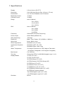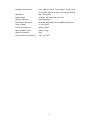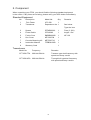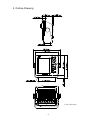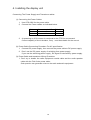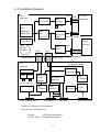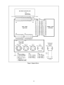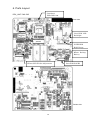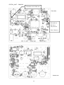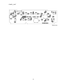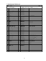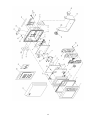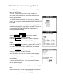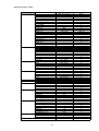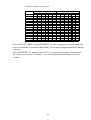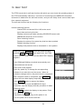
1
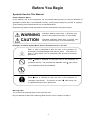
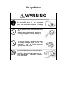
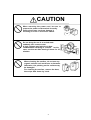
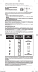
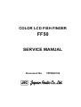
COLOR LCD FISH FINDER
FF50
SERVICE MANUAL
Document No.
7ZPBS4104
General Information
This service manual describes the maintenance and inspection procedures for the
FF50.
Prior to the installation, users are requested to read this manual well and
familiarize with its contents so that an optimum function may be derived from the
FF50.
Note that the grounding work is indispensable to prevent electric shock hazards
as well as to ensure the intended function of the set. Don’t try to ignore the
grounding work.
For the operation of the set, refer to the Instruction Manual.
1
Before You Begin
Symbols Used In This Manual
Related Symbols Marks
In this manual, and on the equipment, we use several warning signs to call your attention to
important to items that, if not handled correctly, could present danger to yourself or property.
These warning note classifications are as described below.
Please be fully aware of the importance of these items before using this manual.
WARNING
Indicates warning items that, if ignored, may
result in serious personal injury or even death.
CAUTION
Indicated cautionary items that, if ignored, may
result in personal injury or physical damage.
Examples of Related Symbol Marks Used in this Manual and on the Unit
Hot Surface
Each △ mark is intended to alert the user to the presence of
precautions including danger and warning items. The picture in
each △ mark alerts you to operations that should be carefully
performed.
Each
marks is intended to alert the user to the presence of
prohibited activity. The picture/word in/beside each
Prohibition
mark alerts
you to operations that are prohibited.
Prohibitions
disassembly
Each ●mark is intended to alert the user to the presence of
necessary instructions.
Instruction
The picture in each ● mark alerts you
to operations that must be performed.
Warning Label
You can see the warning label on the top of the unit.
Do you attempt to remove the warning label from the unit or impair or modify it.
2
Usage Hints
WARNING
When installing this set, be sure
the grounding wire to the
terminal of the set. Otherwise,
shock can result when a failure
occurred on the set.
to connect
grounding
an electric
or leakage
Do not damage, break or modify the power
cord.
Placing a heavy load, heating, pulling or
forcibly bending the cord can damage it
resulting in a fire or an electric shock.
Do not use this set at a voltage other than
the supply voltage stated on the set.
Otherwise, a fire, an electric shock or
system failure can result.
Do not touch inside the set with wet hands.
When your hands are wet, don’t try to
connect or disconnect the power cord or
touch the switches. Otherwise, an electric
shock can result.
3
CAUTION
When removing the power cord, be sure to
remove the power cord terminal correctly.
Pulling the power cord can damage it
resulting in a fire or an electric shock.
No
Do not bring the set in a cooled state
suddenly into a warm room.
A high voltage may leak due to dew
condensation resulting in a failure. In this
case, use the set after leaving it alone for 30
minutes.
4
Thinne
r
benzene
When cleaning the surface, do not use any
organic solvent such as thinner or benzene.
Otherwise, the painting on the surface may
be damaged.
For cleaning the surface, remove the dust,
then wipe with clean dry cloth.
Index
General Information ・・・・・・・・・・・・・・・・・・・・・・・・・・・・・・・・・・・・・・・・・・・・・・・・・・・・・・・1
Before You Begin ・・・・・・・・・・・・・・・・・・・・・・・・・・・・・・・・・・・・・・・・・・・・・・・・・・・・・・・・・2
Usage Hints・・・・・・・・・・・・・・・・・・・・・・・・・・・・・・・・・・・・・・・・・・・・・・・・・・・・・・・・・・・・・・3
Index・・・・・・・・・・・・・・・・・・・・・・・・・・・・・・・・・・・・・・・・・・・・・・・・・・・・・・・・・・・・・・・・・・・・5
1. Specifications ・・・・・・・・・・・・・・・・・・・・・・・・・・・・・・・・・・・・・・・・・・・・・・・・・・・・・・・・・・・・6
2. Component ・・・・・・・・・・・・・・・・・・・・・・・・・・・・・・・・・・・・・・・・・・・・・・・・・・・・・・・・・・・・・・8
3. Outline Drawing ・・・・・・・・・・・・・・・・・・・・・・・・・・・・・・・・・・・・・・・・・・・・・・・・・・・・・・・・・・9
4. Installing the display unit ・・・・・・・・・・・・・・・・・・・・・・・・・・・・・・・・・・・・・・・・・・・・・・・・・10
5. Circuit Block Diagram ・・・・・・・・・・・・・・・・・・・・・・・・・・・・・・・・・・・・・・・・・・・・・・・・・・・・11
6. Parts Layout ・・・・・・・・・・・・・・・・・・・・・・・・・・・・・・・・・・・・・・・・・・・・・・・・・・・・・・・・・・・・13
7. Mechanical Parts List ・・・・・・・・・・・・・・・・・・・・・・・・・・・・・・・・・・・・・・・・・・・・・・・・・・・・16
8. Master Reset and Language Select ・・・・・・・・・・・・・・・・・・・・・・・・・・・・・・・・・・・・・・・・18
9. NMEA0183 INPUT/OUTPUT SENTENCES ・・・・・・・・・・・・・・・・・・・・・・・・・・・・・・・・・21
10. SELF TEST・・・・・・・・・・・・・・・・・・・・・・・・・・・・・・・・・・・・・・・・・・・・・・・・・・・・・・・・・・・・・22
5
1. Specifications
Display
6.5 inch Color LCD (TFT)
Resolution
234×320 dots (Screen Size 133 mm× 97 mm)
Presentation
8 or 16 Color Gradation with 2 Patterns
Brightness Control
10 steps
Contrast Control
10 steps
Range
Auto or Manual
5 to 1,500 m
10 to 5,000 ft
3 to 1,000 fm
Shift
Auto or Manual
0 to 1,000m
0 to 3,000ft
0 to 600fm
Frequency
200 kHz/50 kHz (Dual Frequency)
Power Output
600 W RMS (4,800W P-P)
Gain (Sensitivity)
100 steps
Depth Unit
Meter, Feet, Fathom, SP (0.3000 to 1.9999 m)
Speed Unit
Knots, Mile/h, Km/h
Noise Suppression
Selectable (0 to 15 level)
Interference Rejection
Selectable (OFF, IR1, IR2)
STC
Selectable (Short, Mid, Long)
Water Temperature
32.0 degree Fahrenheit to 100.0 degree Fahrenheit
(0.0 degree Centigrade to 40.0 degree Centigrade)
Boat Speed
0 to 70 Knots
Trip Log
(Only at the STD/ 0 to 999 NM Navigation type 1 or 2)
Display Modes
1) STD (LF or HF)
2) STD (LF)/STD (HF)
3) STD/A-Scope (LF or HF)
4) STD/A-Scope (LF)/STD/A-Scope (HF)
5) STD/Zoom (LF or HF)
6) STD/Auto Zoom (LF or HF)
7) STD/Bottom Lock (LF or HF)
8) STD/Bottom Discrimination (LF or HF)
9) STD/Dual Frequency Mixed
10) STD/Navigation type1 (LF or HF)
11) STD/Navigation type2 (LF or HF)
Simulator
Built-In
6
Audible-visual alarms
Fish, Shallow, Deep, Temp Upper, Temp Lower,
Temp Rate, Arrival, Anchor, Off Course, DGPS
Waypoints
Max. 400 points.
Route plans
10 plans, 40 waypoints per route.
Memory Backup
Includes Battery
Option NAVAID Input
GPS100/DGPS200 sensor NMEA0183 format
Input Voltage
12 to 24 VDC
Power Consumption
Approx. 25 W
Mass (Display Unit)
8.8 lbs (4 kg)
Water Resistance
IPx5
Environmental Conditions
-10℃ to +50℃
7
2. Component
When unpacking your FF50, you should find the following standard equipment
in the carton. If any items are missing, please notify your JRC dealer immediately.
Standard Equipment
No
Description
Model No.
Qty.
1
Fish Finder
JFC-500
2
Transducer
Depends on the 1
Remarks
1
See below
Type the item
3
Spares
5ZFAD00362
1
Fuse (3.15A)
4
Power Cable
CFQ-6382
1
length 1.5m
5
Ferrite Core
5MBBB00002
1
NF-130
6
Sun Cover
MTV302704
1
7
Console Mounting Kit
MPTG30716
1
8
Instruction Manual
7ZPBS2106B
1
9
Warranty Card
1
Transducers
Model No.
Frequency
Remarks
CFT-2501TFA
200 kHz/50 kHz
Transom type dual frequency with
speed and temp. sensor
CFT-2501HFA 200 kHz/50 kHz
Through hull type dual frequency
with speed and temp. sensor
8
3. Outline Drawing
Unit :inch(mm)
9
4. Installing the display unit
Connecting The Power Supply and Transducer cables
(1) Connecting the Power Cables
1,
Use CFQ-6382 for the power cable.
2,
Connect the Power cables as indicated below.
Cable
Black
Red
3.
Connector pin NO.
1
2
Polarity
+
At powering on,2.5A current is conduced to the FF50 for one second.
Current capacity of circuit breaker, if any , must be suitable for the current.
(2) Power Cable Connecting Procedure For AC specification
1.
Connect DC power supply ,then connect the power cable to DC power supply.
2.
Don’t use the DC power supply of switching form power supply.
If you use the switching power supply , RX signal is interfered by power supply.
(3) Power Cable and transducer Wiring Procedure
1. Don’t try to bundle the radio equipment coaxial cable and the audio speaker
cable with the Fish finder power cable.
Such practice can generate noise on the radio and audio equipment.
10
5. Circuit Block Diagram
DPU
J302
CML-595
IC306
LCD
LCD Control
Interface
IC301,302
DATA
TFT LCD
7WSBS7001
RV600
ROM
7DEBS7042
IC300
T700,701
7DEBS7043
32bit
TR702,703
RISC CPU
Inverter
J702
Backlight
IC304
PANEL
Backup RAM
CCK-829
IC312
BT301
J303
Panel
Battery
J300
J301
Interface
7ZCBS7017
W401:BLUE
W400 :WHITE
TRX
Regulated Voltage
CMN-526
IC180
CD431
RX IC
TX Rectifier
FL140
RV140
FL141
TR203,204
TX FET
PHT480,481
2SK1316
NMEA RX
T430
PS TRANS
RV141
RX Receiver
TR430
T202
IC480
IC410
TX TRANS
NMEA TX
PS Control
J402 TRANSDUCER
J404 NMEA I/O
J403 GPS
These VR is adjusted in manufacture.
Don’t Remove VR adjustment.
RV600
LCD Flicker Adjustment
RV140, RV141 RX GAIN Adjustment
11
PS FET
2SK1620
J402 Power Cable
12
6. Parts Layout
J301&302
DPU_UNIT CML-595
FOR CMN-526
Parts side
J702 FOR LCD
Backlight
INVERTOR
HighVoltage
BT301 Backup
Battery
RV600 LCD Flicker Adjustment
J303 FOR PANEL
Solder side
13
PS/TRX_UNIT
CMN-526
W400&401 For CML-595
Parts side
RV140&141
RX Gain
Adjustment
Don’t Remove
Solder side
14
PANEL_UNIT
Parts side
15
7. Mechanical Parts List
Parts List
(Model Number)
FF50(JFC-500)
Item
PART NAME
1
Front Panel Ass‘y
2
Gasket
3
Contact Rubber
4
Light Guide
5
Seald Case
6
φ28 Knob
7
Cap
8
LCD Unit
9
DPU Unit
10 Plate
11 Radiation Case
12 Rubbber Packing
13 Radiation Seet
14 Bush
15 Main Unit
16 Panel Unit
17 Radiation Seet
18 Label
19 Label(Warning)
20 Label(Warning)
21 Rear Cabinet Ass‘y
-1 Rear Cover
-2 Sponge Rubber
-3 Rubber Spaser
-4 Seet
22 Bracket
23 Knob
24 Sun Cover
25 Tapping Screw
26 Tapping Screw
27 Tapping Screw
28 Tapping Screw
29 Screw
30 Screw
31 Screw
32 Rubber Washer
33 Washer
34 Washer
35 Washer
36 Mount Kit
37
38
39
40
Page 1/1
(Title)
COLOR
LCD
Q`tyPART NUMBER
1 MPBC34289
1 MTV302538
1 MTV302660
1 MTV302664
1 MTB347026
1 MPHD30171
1 MPPK30372
1
1
1 MTB344485
1 MTB349940
1 MTT305900
1 MTT306641
1 BRNG00206
1
1
1 MTT306524
1 MPNN37019
1 MPNN35234A
1 MPNN35688
MPBX36626
1 MTC300800
2 MTV302756
2 MTT305975
1 BRPK05061
1 MTB344486
2 MPTG30053
1 MTV302704
8 BRTG04818
13 BRTG03437
4 BRTG04241
7 BRTG03095
8 BSNA03006S
1 BSBB04010B
1 MPTG30149
8 MTT301458A
11 BSLW03000B
2 BSFW04000B
1 BSSW04000S
1 MPTG30716
16
FISH
FINDER
DESCRIPTION
H-7WSBS7001
CML-595
CMN-526
CCK-829
High voltage
Hot surface
φ3x16 SUS Ptype
φ3x12 Fe ZMC Ptype
φ2.6x6 Fe Ptype
φ3x8 Fe ZMC Btype
M3x6 Fe ZMC
BB4x10 Bs
For Setting
LW3Bs
W4Bs
SW4
17
8. Master Reset and Language Select
A MASTER Reset can be performed by either the SOFT
Reset or HARD Reset.
The SOFT Reset restores all set values except the
WAYPOINT data and ROUTE PLAN data to the original
factory set-up values.
The HARD Reset restores all set values to the original
factory- set values and deletes the WAYPOINT and ROUTE
PLAN data.
When you want to keep the WAYPOINT and ROUTE PLAN
data, execute the SOFT reset. When the MASTER reset is
executed, the CUSTOM DEFAULT is initialized to the
factory-set default settings.
When you push to BRT/PWR turn the power on while
pushing CUSTOM and MENU at the same time, the
LANGUAGE SELECT display appears.
Press the JOYSTICK up or down to select a language
and push it in to open the MASTER RESET type select
display.
Press the JOYSTICK up or down to select HARD or SOFT
and push it in to select OK or CANCEL for the selected
language and the reset type.
Press the JOYSTICK to the left or right to select OK and
push it in to execute the MASTER reset.
Select CANCEL and push the in to return to the language
select display.
After the MASTER reset is executed, the FF50 is rebooted
automatically.
To abort the MASTER reset, turn the power off and then
turn the power on again.
Note:
When a backup error occurs, the FF50 enters the MASTER
Reset
mode automatically, and the language select menu opens.
In this case , you cannot abort the MASTER reset. Be sure
not to turn the power off during the MASTER reset.
18
MASTER RESET TABLE
Item
Selected Language
BackLight
Contrast
Range
ZoomRange
Shift
Gain
DisplayMode
AoutMode
FishAlarm
ShallowAlarm
DeepAlarm
TempUpperAlarm
TempLowerAlarm
TempRateAlarm
ArrivalAlarm
AnchorAlarm
OffCourseAlarm
DGPSAlarm
Buzzer
Menu
Navigation
Installation
Graph Scale
Unit
Calibration
GPS Setting
DGPS Setting
Defoult Settings
Other
English,Italian
←
10
←
5
60
200
←
x2
←
0
←
HF=3.5,LF=3.5
←
STD DUAL
←
MANUAL
←
OFF
OFF,32
OFF,10
OFF,164
OFF,50
OFF,60.0
OFF,15.6
OFF,50.0
OFF,10.0
OFF,0.5
OFF,0.2
←
OFF,0.01NM
←
OFF,0.01NM
←
OFF,0.01NM
←
OFF
←
ON
←
9
←
0
←
OFF
←
Short
←
OFF
←
ON
←
M1
←
OFF
←
see table1
←
see note1
←
see note1
←
Auto
←
Route1
←
0.1
←
OFF
←
OFF
←
Int
←
Int
←
Ant
←
HF=C,LF=C
←
Ratio
center=98、range=196 center=30,range=60
center=60、range=40 center=15,range=22
MT
FT
←
1.0000
゜C
゜F
←
KTS
←
0.0
←
0.0
←
0.0
←
0.0
←
HF=0,LF=0
←
−
←
0.0゜
N 00゜00.000' W000゜00.000'
←
←
00:00
←
1
←
WGS-84
←
AUTO
←
10
←
10S
←
none
←
AUTO
←
288.0KHZ
←
100bps
←
HF=0.0,LF=0.0
ChartSpeed
Noise
Interference
STC
Symbols
SampleBar
Colors
Graph
UserColor
Waypoint
Route
SequenceMode
FollowRoute
CDIrange
MonitorMode
Simulator
TempIn
SpeedIn
PositionIn
PDC
ExpandRangeMode
DepthGraphScale
TempGraphScale
DepthUnit
YourDepth
TempUnit
SpeedUnit
Calib.Temp
Calib.Speed
Draft
KeelHeight
GainOffset
ResetLog
MagneticCorr.
Position
TimeDiffrence
AnntenaHeight
GeodeticDatum
FixMode
HDOPlevel
Average
ExcludeSatellite
BeaconReceiveMode
BeaconFrequency
BaudRate
BottomJudgeLevel
19
DEFOULT USER COLOR TABLE
sig.level R
0
1
2
3
4
5
6
7
8
9
10
11
12
13
14
15
0
0
0
0
0
0
5
9
15
15
15
15
15
10
9
8
16-Step Gradation
8-Step Gradation
M1
M2
M3
M4
G
B
R
G
B
R
G
B
R
G
B
0 10
0
0
6
0
0 10
0
0
6
4
8
0
4
8
0
7
9
0
7
9
7 11
0
7 11
0
7
9
0
7
9
9 10
0
9 10
0 10
8
0 10
8
11
8
0 11
8
0 10
8
0 10
8
10
6
0 10
6
0 13
0
0 13
0
15
2
5 15
2
0 13
0
0 13
0
15
0
9 15
0 15 15
0 15 15
0
15
0 15 15
0 15 15
0 15 15
0
9
0 15
9
0 15
7
0 15
7
0
8
0 15
8
0 15
7
0 15
7
0
6
0 15
6
0 15
0
0 15
0
0
0
0 15
0
0 15
0
0 15
0
0
0
0 10
0
0
9
0
0
9
0
0
0
0
9
0
0
9
0
0
9
0
0
0
0
8
0
0
9
0
0
9
0
0
If you select SOFT RESET for MATER RESET, the data of Waypoint and Route created by
users is not deleted. If you select HARD RESET, all the data of Waypoint and Route settings
is deleted.
After HARD RESET, the Waypoint data: WPT1-7 is preset in the Waypoint list and Route
No.1 list as the reference of simulation. You can change the data according to your use
condition.
20
9. NMEA0183 INPUT/OUTPUT SENTENCES
Input sentences
$xxAPA Heading/Track Controller (Autopilot) Sentence ”A”.
$xxAPB Heading/Track Controller (Autopilot) Sentence ”B”.
$xxBWC Bearing & Distance to Waypoint
$xxBWR Bearing & Distance to Waypoint - Rhumb Line
$xxGGA Global Positioning System Fix Data
$xxHDG Heading, Deviation & Variation
$xxHDT Heading - True
$xxMTW Water Temperature
$xxRMC Recommended Minimum Specific GPS data
$xxVTG Course Over Ground and Ground Speed
$xxVHW Water Speed and Heading
Output sentences
$SDDBT Depth Below Transducer
$SDDPT Depth
$SDMTW Water Temperature
$SDAPB Heading/Track Controller (Autopilot) Sentence “B”
Necessary to connect the GPS100 or DGPS200
$SDBWC Bearing & Distance to Waypoint
Necessary to connect the GPS100 or DGPS200
$GPGGA Global Positioning System Fix Data
Necessary to connect the GPS100 or DGPS200
$GPRMC Recommended Minimum Specific GPS data
Necessary to connect the GPS100 or DGPS200
21
10. SELF TEST
The FF50 has a built-in self test function with which you can check the operating status of
the FF50 automatically. Moreover, a function of monitoring input NMEA0183 formatted
sentences is attached to the self test function, and you can easily check various data input
from external equipment.
The self test function has the following four functions.
Internal checking function:
Checks DPU and shows OK or NG as the result.
Input data monitoring function:
Displays various input data including GPS/DGPS sensor and
NMEA0183 sentences on the screen.
Panel checking function:
Displays the status of the panel key that has been pushed.
Display checking function:
Displays test patterns such as crosshatch or color pattern.
When you push BRT/PWR to turn the power on while
pushing AUTO and FREQ at the same time, the FF50
enters the SELFTEST mode and the SELFTEST display
appears.
Then ROM and RAM are checked automatically and
various data as well as the
result (OK or NG) appear.
Push any panel key to change the corresponding
indicator from red to blue on the screen. When all
indicators change to blue, the panel check is completed.
After the panel check is completed, push CLR/OFF to
pause the input data display temporarily.
Push CLR/OFF again to resume the display.
When you want to check the NMEA0183 input
sentences, stop the display with this procedure to make
checking easier.
Push MENU to switch the display to test pattern. Each
time you push MENU, the
test pattern changes as long as the power is on.
Turn the power off to end the self test.
22
Main Office & Plants
●Main Office
Akasaka Twin Tower(Main)
17-22,Akasaka 2-chome,
Minato-ku,Tokyo 107-8432 JAPAN
Maritime Sales Department
Phone:+81-3-3584-8833
Fax :+81-3-3584-8757
International Business Department
Phone:+81-3-3584-8836
Fax :+81-3-3584-8878
Communications Equipmennt Marketinng
Department
Phone:+81-3-3584-8845
Fax :+81-3-3584-8879
Overseas Subsidiaries
●JRC (UK) Limited
136, 1st Floor, Friars House,
157/168 Blackfriars Road,
London SE18 EZ, U.K.
Phone:+44-20-7261-1188
Fax :+44-20-7803-0996
Overseas Branch Offices
●U.S.A.
U.S.A.
Japan Radio Co.,Ltd./Seattle Branch
1011 SW Klickitat Way
Bldg.B, Suite 100
Seattle, WA 98134 U. S. A.
Phone:+1-206-654-5644
Fax :+1-206-654-7030
Overseas
Liaison & Service
Service Offices
●U.S.A.
U.S.A.
Japan Radio Co.,Ltd.
Nisshin foods Building, Suite 208
2125 Center Avenue, Fort lee N. J. 07024, U. S. A.
Phone:+1-201-242-1822
Fax :+1-201-242-1885
●Indonesia
Japan Radio Co.,Ltd.
GRAHA SURYA INTERNUS 7th F1. (suite 703A)
J1. H.R. Rasuna Said Kav. X-O.
Jakarta 12950, INDONESIA
Phone:+62-21-527-3010
Fax :+62-21-527-3013
●Philippines
Japan Radio Co.,Ltd.
2320 Taft Avenue
Malate,Manila PHILIPPINES
Phone:+63-2-524-8565・525-3589
Fax :+63-2-521-5049
●Thailand
Japan Radio Co.,Ltd.
Charturong Arphon Building
457 Phra Sumaru Street
Bangkok 10200 THAILAND
Phone/Fax:+66-2-280-0401
●India
Japan Radio Co.,Ltd.
Best Western Surya Hotel, Business Centre
New Friends Colony, New Delhi 110065, INDIA
Phone: +91-11-691-9294・691-9297
Fax : +91-11-691-9305
Overseas Service Center
●Mitaka Plant
1-1,Shimorenjaku 5-chome,Mitaka
Tokyo 181-8510 JAPAN
Phone:+81-422-45-9111
Fax :+81-422-45-9110
●Taiwan
Japan Radio Co.,Ltd.
7F No.146,Sung Chiang Road
Taipei TAIWAN
Phone:+886-2-2571-3100
Fax :+886-2-2571-2999
●Spain
Japan Radio Co.,Ltd.
Calle Luis Doreste Silva, 50-1-B De Las
Palmas De Gran Canaria SPAIN
Phone:+34-928-290076
Fax :+34-928-293755
●Singapore
Japan Radio Co.,Ltd.
c/o CODAR(PTE.)LTD.
315 Outram Road #11-06/07 Tan Boon Liat
Building Singapore 169074 SINGAPORE
Phone:+65-2229190
Fax :+65-2229398
●Greece
Japan Radio Co.,Ltd.
57, Akti Miaouli Piraeus GREECE
Phone: +30-1-429-3304・429-3305
Fax : +30-1-429-3306
●Korea
Japan Radio Co.,Ltd.
Room 202, Whadong Bldg. 84-18, 4-GA
Chungang-Dong, Chung-Ku, Pusan, KOREA
Phone: +82-51-441-0035
Fax : +82-51-464-0695
●Netherlands
Japan Radio Co.,Ltd.
Cessnalaan 40-42,1119NL Schiphol-Rijk
THE NETHERLANDS
Phone:+31-20-658-0750
Fax :+31-20-658-0755
00.12
For further information contact:
HEAD OFFICE &
SALES DEPT.
Akasaka Twin Tower (Main),
17-22, Akasaka 2-chome, Minato-ku,
Tokyo 107-8432 JAPAN
Phone : +81-3-3584-8711
Fax : +81-3-3584-8715
Telex : 0242-5420 JRCTOK J
MAIN PLANT
1- 1, Shimorenjaku 5-chome, Mitaka-shi,
Tokyo 181-8510 JAPAN
Phone : +81-422-45-9111
Fax : +81-422-45-9110
Telex : 02822-351 JRCMTK J