1
TR491 dropping-arm tripod turnstile
INSTALLATION MANUAL
Automatic Systems s.a.
Head office & factory:
Avenue Mercator 5, 1300 Wavre, Belgium
Tel.: 32-10-23.02.11 Fax: 32-10-23.02.02
Automatic Systems reserves the right to change the characteristics of its products without notice.
Automatic Systems TR491-TR6-GB-a YD-JMW
MQ-1302
20/01/00
Installation TR491
2-1106GB
Rev.: C
Table of contents
1.
INTRODUCTION...............................................................................................................
p.
3
2.
GENERAL.........................................................................................................................
p.
4
General view...................................................................................................................
Switching off the equipment ...........................................................................................
General conditions of use...............................................................................................
In case of power failure ..................................................................................................
Overall dimensions and installation plan ........................................................................
p.
p.
p.
p.
p.
4
5
5
5
6
INSTALLATION ................................................................................................................
p.
7
First step .........................................................................................................................
Preliminary work on site .................................................................................................
Installing the tripod turnstile............................................................................................
Electrical connections and initial power-up ....................................................................
Check-list ........................................................................................................................
Temporary dismantling ...................................................................................................
3.6.1.
Disconnecting the equipment..........................................................................
3.6.2.
Removing the unit ...........................................................................................
Scrapping the equipment................................................................................................
p.
p.
p.
p.
p.
p.
p.
p.
p.
7
8
8
9
12
12
12
12
12
2.1.
2.2.
2.3.
2.4.
2.5.
3.
3.1.
3.2.
3.3.
3.4.
3.5.
3.6.
3.7.
4.
ANNEX: ELECTRICAL DIAGRAMS (standard version: diagrams Automatic Systems
STD 1TR6 04.001 and BT 1TR6 04.002)
Automatic Systems TR491-TR6-GB-a YD-JMW 20/01/00
Installation TR491
2-1106GB Rev.: C
p. 2/12
1.
INTRODUCTION
We thank you for having chosen the TR491 dropping-arm tripod turnstile designed and
manufactured by Automatic Systems. We are confident that your purchase will fully meet your
requirements. However, in order to obtain maximum satisfaction from this equipment for a
maximum period of time, we strongly advise you to read this manual carefully before installing
the equipment.
Although this manual has been prepared with great care, some information may seem
erroneous or unclear to you. In this case, please do not hesitate to contact us with your
remarks or questions.
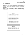
WARNING:
YOUR TR491
DROPPING-ARM TRIPOD TURNSTILE
COMPRISES
A
MECHANISM
AND
VARIOUS
ELECTRICAL COMPONENTS.
ANY NEGLIGENCE
DURING AN INTERVENTION IN THE MACHINE MAY
SERIOUSLY ENDANGER YOUR SAFETY. AS SOON AS
YOU OPEN THE HOUSING, PUT OFF THE MAIN
SWITCH (2:1) ON THE ELECTRICAL CONTROL LOGIC
(2:2), LOCATED UNDER THE HOOD. BE CAREFUL IN
HANDLING ANY INTERNAL ELEMENT WHICH MIGHT BE
UNDER POWER OR COULD BE SET IN MOTION.
WHEN
WORKING ON THE CIRCUITS, IT IS
RECOMMENDED:
- NOT TO DISCONNECT WIRES WITHOUT MARKING
THEIR TERMINALS;
- NOT TO REMOVE THE CONNECTOR WITHOUT
MARKING ITS PRECISE POSITION
IMPORTANT
BECAUSE OF THE
CAUSE, WE ADVISE
SHOCKS THE TURNSTILE COULD
YOU TO PROHIBIT THE ACCESS TO
UNACCOMPANIED YOUNG CHILDREN AS WELL AS TO
ANIMALS.
Automatic Systems TR491-TR6-GB-a YD-JMW 20/01/00
Installation TR491
2-1106GB Rev.: C
p. 3/12
2.
2.1.
GENERAL
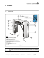
General view
1:12
1:3
1:8
Green arrow:
"PASSAGE IN SERVICE"
Red cross:
"PASSAGE OUT OF SERVICE"
1:5
1:4
1:4
Approach
pictogram (option)
1:7
1:5
1:2
1:4
1:10
1:1
B
1:9
1:6
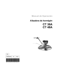
Legend:
1:1 Front end section ("A") (hinged)
1:2 Rear end section ("B") (hinged)
1:3 Hood
1:4 Approach pictogram (option)
1:5 Card reader (option)
1:6 Tripod obstacle with stainless steel arms
1:7 Tripod turnstile mechanism (See Field manual)
1:8 Electrical control logic
1:9 Floor fixing
1:10 Steel housing
1:11 Commercial identification plate
1:12 Lock
1:11
1:9
A
Fig. 1
Note:
Conventionally and as a general rule, the user will be considered in direction "A" when
the turnstile is at his right-hand side, in direction "B" when the turnstile is at his left-hand
side.
Automatic Systems TR491-TR6-GB-a YD-JMW 20/01/00
Installation TR491
2-1106GB Rev.: C
p. 4/12
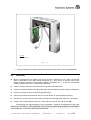
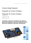
2.2.
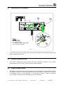
Switching off the equipment
Automatic Systems
Prod.
TR430
Type
A5-B5
N°
5214578
Phase 1
76
Kg
Volts
Hertz
Amp
230
50/60
1
2:2
2:1
2:4
2:5
Legend:
2:1 Main switch
2:2 Control logic
2:3 Earth connector
2:4 Customer power supply cables
2:5 Customer earth cable
2:3
2:1
Fig. 2
•
2.3.
•
2.4.
•
As soon as you open the housing, put off the main switch (2:1) near the electrical control logic
(2:2), located under the hood.
General conditions of use
Your TR491 dropping-arm tripod turnstile has been designed to operate in any climatic
environments of -20°C to +60°C, with up to 90% of relative humidity.
In case of power failure
Whatever the control mode set up, the dropping-arm tripod turnstile has been developed to leave
the walkway clear when the electrical power supply is interrupted. Access by the user will
consequently be free --in both directions-- in an emergency situation. Refer to paragraph
[3.2. Principle of operation] in the Field manual for more information.
Automatic Systems TR491-TR6-GB-a YD-JMW 20/01/00
Installation TR491
2-1106GB Rev.: C
p. 5/12
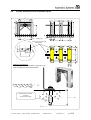
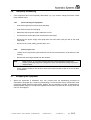
2.5.
Overall dimensions and installation plan
60
50
920
800
60
1000
950
265
20
480
265
500
265
1000
760
26.5
800
26.5
60
Cable ducting
60
145
620
145
620
145
480
265
500
265
Power supply and command
cable inlet area
265
20
50
190
B
B
B
840 1220
A
A
A
190
Cabling to be prepared:
Power supply: 230V single-phase + earth (3G x 2.5)
Control wiring according to specifications
145
265
B
° 15
A
EXPANSION BOLT B15/30
-/3413/000
(recommended model)
min. 100
Fig. 3
Automatic Systems TR491-TR6-GB-a YD-JMW 20/01/00
Installation TR491
2-1106GB Rev.: C
p. 6/12
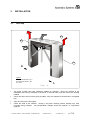
3.
3.1.
INSTALLATION
First step
4:3
4:2
4:1
B
Legend:
4:1 Front end section ( "A")
4:2 Rear end section ( "B")
4:3 Hood
Fig. 4
A
•
The tripod turnstile has been packaged suitable for transport. Move the material to the
installation site with the assistance of a fork-lift, or manual hand truck and remove the packing
material.
•
Unlock and open the front doors (4:1) and (4:2). Keys are supplied as accessories in a separate
bag.
•
Open and remove the hood (4:3).
•
Check the state of the material. Though it has been carefully packed, damage may have
occurred during transport. Any transportation damage should be repaired, or components
replaced.
Automatic Systems TR491-TR6-GB-a YD-JMW 20/01/00
Installation TR491
2-1106GB Rev.: C
p. 7/12
3.2.
•
Preliminary work on site
This is basically the following:
Check the positioning and location of the equipment according to the site's general lay-out.
Preparation of fixing holes in the floor as in Fig. 3. Make sure to drill holes with the diameter
adapted to the expansion bolts that will be used (type recommended: model B15/30, ref.
-/3413/000). Ensure that the drilling positions do not conflict with any cables, pipes, ducts or
steelwork in the floor structure. If this does occur, a slight repositioning of the turnstile may
be needed.
Preparation of electrical supply and control cabling: all power and control cables enter the
turnstiles through the floor at either end section (rear or front). Mark and drill entry holes in
floor as described for the fixing holes. A single-phase, 230V 2Amp (max.) power supply is
required, installed to the country Regulations, relevant for this installation, complete with
earth bonding for the metalwork. Control cables for remote desk consoles (if supplied), and
other access control devices (when applicable) will also be required, installed to conform
with relevant regulations and control device specifications.
Note:
Note:
3.3.
All cables to have a 2 meter tail.
If you add any flammable elements (see EN60950, paragraph 4.4.5. standard) into the
end sections of the turnstile, make sure that the floor is fireproof.
Installing the tripod turnstile
•
Position the turnstile on site precisely.
•
Fix the 4 expansion bolts to the floor.
•
Put the two fixing brackets inside the front and rear end sections, at the bottom of the housing, as
illustrated in Fig. 3. The fixing brackets are supplied as accessories.
•
Carefully pull the power or control cables into the end sections of the turnstile (ensure cables are
not trapped between the floor and the end sections or the fixing brackets).
•
Check turnstile for alignment and level, and tighten fixing brackets firmly.
•
When the turnstiles are fitted in banks (rows), of more than 1 unit, attention should be given to the
linear, vertical and horizontal alignment. Packing shims can be used.
Automatic Systems TR491-TR6-GB-a YD-JMW 20/01/00
Installation TR491
2-1106GB Rev.: C
p. 8/12
3.4.
•
Electrical connections and initial power-up
The electrical connections must be made according to the diagrams affixed inside the housing.
Ö
Make sure that the power supply cables are not live. All internal connections are factorymade.
Ö
If necessary, cut off the excess cable length. Connect the 230V single-phase power supply
wires (2:4) to the terminals on the main switch (2:1), and the earth wire (2:5) to the adjoining
terminal (2:3). Make sure the equipment is correctly earth bonded (housing & associated
metalwork).
Ö
Proceed with all other electrical connections depending on the equipment specifications
(control wiring, etc.).
Ö
Route all cables via the cable entry holes and secure in the cable fastenings provided,
ensuring that they are held clear of the turnstile mechanism's moving parts.
Ö
After the power supply from the remote isolator has been energised, test for correct polarity,
supply voltage and earthing, power up the equipment by putting the main switch (2:1) to the
ON position.
Note: When the turnstile is connected to an IT power system, a 2A two pole circuit breaker
must protect the 230V power supply.
Automatic Systems TR491-TR6-GB-a YD-JMW 20/01/00
Installation TR491
2-1106GB Rev.: C
p. 9/12
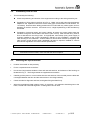
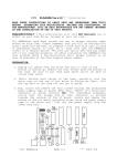
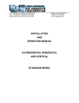
TR6 CONTROL LOGIC
X1
R2 R1
R5
R3 R4
Q2
R8
Q5
R21
R20
R9
LD6 Q8
LD7 Q10
R19
Q3
EMI2
X6
Q7
Q9 X7
D3
EMI5
EMI6
Q11
R34 R37
R36
R35R12
LD2
D2
R16
R14
EMI8 R13 R15
EMI1
X5
PL1
AS1026R2 board
EMI3
Q1 R27 R28EMI4
EMI7 R11
R26 R29
R10R30R31
R32
R33
LD1
X2
R18
LD3
5:21
IC2
R22
R17 R23R24
R25
Q4
LD5 LD4
Q6
C6
SW1
1
C1C3
IC3
IC1
5:20
R7 R6
C4
C5
X4
C2
AS
1026R2
PL2
5:6
5:3
5:5
5:16
5:17 5:7
5:8
5:9
AS1025R2
5:18
5:1
5:10
5:11
5:19
5:12
5:4
5:2
5:14
5:15
5:13
AS1025 board
1. 230V main power supply connector
2. Fuse 1: T500mAL 250V (230V power supply)
3. 60VA multivoltage transformer
4. AS1025 board
5. Fuse 2: T2AL 250V (24VDC voltage)
6. I2C expansion connector
7. Parameter programming DIP switches
8. DIP switches for selecting operation mode
and programming parameters
9. "AS-LINK" connector for programming console
10. Programming push button and LED
11. RS232 line TTL 5V level
12. Customer input/output connector
13. Signal relay
14. Direction A and B limit switches connector
15. Direction A and B electromagnets connector
16. Application microcontroller
17. Microcontroller reset button
18. Direction A and B simulation buttons
19. 230V power supply filter
AS1026 board
6. I2C expansion connector
20. Dropping arm test button
21. Dropping arm connector
Fig. 5
Automatic Systems TR491-TR6-GB-a YD-JMW 20/01/00
Installation TR491
2-1106GB Rev.: C
p. 10/12
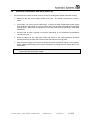
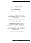
6:1
Legend:
6:1 Walkway arm
Fig. 6
Ö
3.5.
Lift up the walkway arm (6:1) manually and make sure this holds in the horizontal position.
Check-list
Before commissioning the dropping-arm tripod turnstile, proceed with the various mechanical
tests as described in the Field manual paragraph [2.1. First service at 50,000 cycles], then
electrical (proper operation of the optional readers, pictograms, etc.). In case of a mechanical
problem, please refer to the corresponding paragraph.
Check if all wires are firmly connected to their respective terminal blocks.
Check if the tripod's walkway arm (6:1) falls down when the electrical power supply is interrupted.
Check if all screws and nuts have been tightened firmly.
Inspect the inside of the turnstile to ensure no tools remain, to cause equipment failures.
Remove any foreign body from the inside of the tripod turnstile (packing, debris, etc.), and clean.
Position the hood back(4:3) and lock it. Close and lock the front doors (4:1) and (4:2).
-The dropping-arm tripod turnstile is now operational. Although all adjustments have been
carried out in our factory, a final adjustment may be required, following transportation and installation
of the equipment. In this case, refer to the Field manual.
Automatic Systems TR491-TR6-GB-a YD-JMW 20/01/00
Installation TR491
2-1106GB Rev.: C
p. 11/12
3.6.
•
Temporary dismantling
If the equipment has to be temporarily dismantled, e.g. if you need to change its location, follow
the procedure below.
3.6.1.
--
Unlock and open the front doors (4:1) and (4:2).
--
Unlock and remove the hood (4:3).
--
Make sure that the power supply cables are not live.
--
Put off the main switch (2:1) near the electrical control logic.
--
Disconnect the power supply wires (2:4) from the main switch (2:1) as well as the earth
cable (2:5).
--
Disconnect any other cabling (control wires, etc.).
3.6.2.
Loosen the four expansion bolts inside the front and rear end sections, at the bottom of the
housing.
--
Remove the two fixing brackets from the turnstile.
--
•
Removing the unit
--
Note:
3.7.
Disconnecting the equipment
Either remove, or cut off floor fixing expansion bolts and make good the floor
surface, protruding fixings are a dangerous risk to the health and safety of persons
using the area.
Using manual handling or fork-lift truck remove the tripod turnstile to safe or its new location
for installation.
Scrapping the equipment
When the equipment is withdrawn from use, proceed with the dismantling procedure as
described in paragraph [3.6. Temporary dismantling]. Ensure that the various components of the
equipment (metals, electrical components, plastics, etc.) are handled, recycled, or disposed of in
the appropriate method, to comply with regulations and codes of practice in the country where the
unit is to be scrapped.
Automatic Systems TR491-TR6-GB-a YD-JMW 20/01/00
Installation TR491
2-1106GB Rev.: C
p. 12/12