1
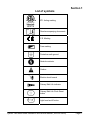
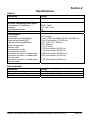
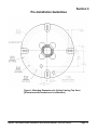
MH SYSTEMTWOSURGICALLIGHTINGSYSTEM INSTALLATIONAND SERVICEMANUAL MEDICALILLUMINATIONINTERNATIONALINC. WHERE ILLUMINATION IS DEFINED MH Agency Approvals Medical Electrical Equipment With respect to electric shock, fire And mechanical hazards only In accordance with UL60601-1:2006 / CAN/CSA C22.2 No.601.1-M90 with updates 1 & 2. Classifications: 1. Protection against electrical shock (5.1, 5.2). Class I permanently connected, 2. Protection against harmful ingress of water (5.3). None. 3. Degree of safety in the presence of flammable anesthetics or oxygen (5.5). Not suitable for use in the presence of flammable anesthetics or oxygen. 4. Mode of operation (5.6). Continuous. 5. Surgical luminaries (IEC60601-2-41) Minor. Electromagnetic compatibility for immunity And emissions in accordance with EN-60601-1-2(2001) Class B and CISPR 22 (1997) Class B Medical Electrical Equipment Particular requirements for the safety of surgical luminaries and luminaires for diagnosis In accordance with IEC-60601-2-41 Intended use The System Two surgical lighting system is an AC powered device which provides a focusable field of illumination for general examination and surgery. System Two Metal Halide Installation and Service Manual (1003328 Rev B) Page 2 Table of Contents Section 1: Terminology Definition of terms List of Symbols Section 2: Specifications Mechanical Specifications Electrical Specifications Optical Specifications Environmental Specifications Floor Mount Specifications Warranty Section 3: Installation Pre-installation Guidelines Solo Ceiling Mount Installation Duo Ceiling Mount Installation Trio Ceiling Mount Installation Floor Mount Installation Section 4: Operating Instructions Light Head Position Adjustment (arm operation) Turning Light Head on/off Light Pattern Dimming Function Light Pattern Adjustment Section 5: Safety Instructions General Safety Instructions Section 6: Maintenance Lamp Replacement Fuse Replacement Arm Tension Adjustment Head Friction Adjustment Arm/Head Friction Adjustment Handle Sterilization Cleaning Instructions Maintenance Schedule System Two Metal Halide Installation and Service Manual (1003328 Rev B) Page 3 Table of Contents (Continued) Section 7: Troubleshooting General Trouble Shooting Section 8: Exploded Views and Parts List Electrical Schematic Ballast Assembly Ceiling Casting Assembly Ceiling Rod Assembly Arm assembly Light head assembly Extension/Adapter Solo Assembly Duo Assembly Trio Assembly System Two Metal Halide Installation and Service Manual (1003328 Rev B) Page 4 List of Figures Figure Number and Description Figure 1- Mounting Dimensions for Ceiling Casting Figure 2- Ceiling Rod Calculation Solo Ceiling Mount Figure 3- Ceiling Rod Calculation Duo Ceiling Mount Figure 4-Ceiling Rod Calculations Trio Ceiling Mount Figure 5- Sub-assemblies for Solo Ceiling Mount Figure 6- Ceiling mount Figure 7- Unpacking Figure 8- Installation setup Figure 9- Arm and ceiling assembly Figure 10- Ceiling & Shaft Dowel Pin insertion Figure 11- Ceiling & Shaft Dowel Pin locking Figure 12- Arm cable termination Figure 13- Locking Pin Removal Figure 14- Floor Mount Dimensions Figure 15- Floor Stand Light Installation Figure 16- Arm Assembly to Upright Pole Installation Figure 17- System Two Head and Arm Movements Figure 18- Floor Stand and Arm Movements Figure 19-Lamp Replacement Figure 20-Fuse Replacement Figure 21-Arm Adjustment Figure 22-Light Head Friction Adjustment Figure 23- Arm Friction Adjustment Figure 24- Handle Sterilization System Two Metal Halide Installation and Service Manual (1003328 Rev B) Page Number 14 15 16 17 18 19 20 21 23 24 25 26 27 28 29 31 32 33 37 38 39 40 41 42 Page 5 Section 1 Definition of Terms I.E.C. International Electrotechnical Commission ETL Edison Testing Laboratories Medical Electrical Equipment Electrical equipment intended to diagnose, treat the patient under medical supervision. Electrical equipment that transfers light energy to the patient. Central Illuminance Illuminance of light head measured at 1 meter from the light emitting area with no obstructions. The value is expressed in Foot-candles or Lux. Light Field Center The point of maximum illuminance in lighted area. This is the reference point for light field size and light distribution measurements. Light Field Diameter The diameter of the circle where illuminance reaches 10% of light field center illuminance. Depth of Illumination The distance above and below 1 meter to where the central Illuminance is reduced to 20%. Shadow Dilution The ability of the equipment to minimize the impact of shadows in the working area due to partial obstruction by the operator or other medical personnel. Correlated Color Temperature The color temperature of the light fixture when compared to a blackbody radiator expressed in degrees Kelvin. Total Irradiance The total amount of energy imparted to the patient by the lighting system expressed in Watts/meter squared. Color Rendering Index (CRI) A method of how well a light source will render other colors when illuminating them based upon eight CIE chromaticity coordinates measured with a spectroradiometer. Sterilizable Handle An easily removable device that when properly sterilized maintains a sterile area in order to handle it under aseptic conditions when attached to the equipment. System Two Metal Halide Installation and Service Manual (1003328 Rev B) Page 6 Section 1 Definition of Terms (continued) Light Head/Articulating Arm Assembly: That part of the device which includes the light source, heat removal system, light focusing system and light head vertical positioning arm. Extension Arm Horizontal section of the positioning arm with pivots on both ends that is used to increase the area covered by the light head and articulating arm Light Mounting Support apparatus used to connect light head/articulating arm assembly to a fixed surface, consisting of either a single, double or triple ceiling mount. Neutral Conductor In an AC circuit, the return line for current. Protective earth ground The conductor used to connect the non-current-carrying metal parts of equipment, raceways, and other enclosures to the system grounded conductor, the grounding electrode conductor, or both, of the circuit at the service equipment or at the source of a separately derived system. Ft-Lbs Foot-pounds. The unit of measurement of torque which is caused by an off-center load. System Two Metal Halide Installation and Service Manual (1003328 Rev B) Page 7 Section 1 List of symbols ETL Listing marking Read accompanying documents C.E. Marking Fuse marking Protective earth ground Neutral conductor Caution Electric shock hazard Primary Bulb Life indicator Primary Bulb Life Clock Reset button Light head on/off button System Two Metal Halide Installation and Service Manual (1003328 Rev B) Page 8 Section 2 Specifications Mechanical Parameter Weight Value Solo ceiling mount assembly Duo ceiling mount assembly Trio ceiling mount assembly Light head assembly Approximately 73.5 lbs (33.3 Kg). Approximately 104.5 lbs (47.4 Kg). Approximately 155.5 lbs (70.5 Kg). Approximately 23.5 lbs (10.7 Kg). Dimensions Ceiling casting Ceiling rod (See fig’s 2,3 & 4) Arm (articulated) Light head assembly Rotations 17.0” (431.8 mm) Dia x 4.7” (119.4 mm) deep 2.5” (63.5 mm) Dia x 9.0”-43.0”(228.6 -1092.2 mm) long (depending on ceiling height) 3.5” (88.9 mm) Dia(tapered) x 26 0“ (660.4 mm) long 23.0” (584.2 mm) diameter x 10.0” (254mm) deep Ceiling mount/extension arm interface Articulating/extension arm interface Articulating arm vertical movement Articulating arm/Yoke interface Yoke/lamp head interface Continuous Continuous +20, -70 Degrees Continuous +/- 150 Degrees Electrical Parameter Voltages Value Input Voltage Lamp voltage Bulb life Power Solo (SS2120 MH, SS2230 MH) Duo (SS2S2120 MH, SS2S2230 MH) Trio (SS2S2S2120 MH, SS2S2S2230 MH) 100 - 125 VAC 50/60 Hz 220 - 240 VAC 50/60 Hz 120 VAC 50/60 Hz (39 Watts) Primary 24 – VAC 50/60 Hz (80 Watts) Secondary 10,000 hours (average) For Primary 120/230 VAC, 50/60 Hz 140 Watts 120/230 VAC, 50/60 Hz 280 Watts 120/230 VAC, 50/60 Hz 420 Watts System Two Metal Halide Installation and Service Manual (1003328 Rev B) Page 9 Section 2 Specifications Optical Parameter Value Reflector 20” (508mm) diameter polished aluminum, facetted IR/Color correcting filter glass Corrected color Temperature Irradiance Color Rendering Index 4300 Kelvin 314 W/m2 (1m) 90 Parameter Performance Value Focal length Central illuminance(adjustable) Maximum illuminance @33” Light field diameter(adjustable) Depth of illumination Diameter (d50) Illuminance(one mask) Illuminance(two masks) Illuminance at bottom of standard tube Illuminance at bottom of standard tube with one mask Illuminance at bottom of standard tube With two masks 39” (1 meter) 2,500- 9,290 foot-candles (26,909 -100,000 Lux) 10,500 foot-candles (113,018 Lux) 5.62 - 9.85” (143 - 250mm) 48” (1,220mm) 4.12” (105mm) 2,735 foot-candles (29.500 Lux) 4,126 foot-candles (44,500 Lux) 9,829 foot-candles (106,000 Lux) 2,875 foot-candles (31,000 Lux) 4,312 foot-candles (46,500 Lux) Environmental Parameter Value Operating temperature Storage temperature Range Humidity 41 - 104 deg F (5-40 Degrees Celsius) 41 - 104 deg F (5-40 Degrees Celsius) 10 - 90% relative humidity System Two Metal Halide Installation and Service Manual (1003328 Rev B) Page 10 Section 2 Specifications (Floor Model) Mechanical Parameter Weight Value Floor base with upright. Arm assembly MH Light Head Approximately 88.5 lbs (40,1 Kg) Approximately 16.3 lbs (7,4 Kg) Approximately 23.5 lbs (10.7 Kg) Dimensions Floor base Upright Arm assembly 7.5” (190,5 mm) high x 28” (711,2 mm) long x 25” wide (635 mm) 2.5” (63,5 mm)Dia 79” (2006,6 mm) 3.5” (88,9 mm) Dia (tapered) x 26.0” (660,4 mm) long Rotations Articulating arm interface vertical movement Articulating arm/upright interface horizontal movement +20 Degrees, 70 Degrees +/- 7.5 Degrees Electrical Parameter Power Value FS2120 MH, FS2230 MH, 120 VAC, 50/60 Hz, 140 Watts 230 VAC, 50/60 Hz, 140 Watts System Two Metal Halide Installation and Service Manual (1003328 Rev B) Page 11 Section 2 Medical Illumination International, Inc. Lighting Equipment Limited Warranty Medical Illumination International, Inc. Lighting Equipment is warranted against defective material and/or workmanship, excluding normal replacement parts (e.g. bulbs or glass items), for a period of three (3) years from the date of shipment. This warranty applies exclusively to the repair or replacements of parts recognized as defective by Medical Illumination International, Inc., are in normal use, and have not been modified or repaired by unauthorized personnel. This warranty supersedes all other guarantees or warranties, expressed or implied. In the event of a failure covered under this warranty, please take the following action: 1. Call the Medical Illumination Customer Service Department at (818) 838-3025. Be prepared to give the model number, serial number, and full description of the failure. Customer Service will attempt to solve the problem over the phone. If it becomes necessary to send the product to the factory for repair, Customer Service will provide a Return Authorization number. No product should be returned without a Return Authorization number. 2. Carefully package the light component (light head, arm assembly, or mount assembly) and return it, freight prepaid and insured, with the Return Authorization number clearly marked on the box, to: Medical Illumination International, Inc. 547 Library Street San Fernando, CA 91340 RA# Damage resulting from inadequate packing is not covered by this warranty and shipping insurance does not cover damage from inadequate packing. We recommend that the package be insured against loss or in-transit damage. Medical Illumination can not be responsible for in-transit loss or damage. 3. DAMAGE TO THE PRODUCT RESULTING FROM TAMPERING, ACCIDENT, ABUSE, NEGLIGENCE, OR OTHER CAUSES UNRELATED TO PROBLEMS WITH MATERIAL AND/OR WORKMANSHIP, ARE NOT COVERED BY THIS WARRANTY. 4. Warranty may be voided if equipment is found to have been installed incorrectly, resulting in equipment failure. 5. This warranty does not cover any labor costs associated with removing, re-packaging for shipment or reinstalling this product. Such costs are the responsibility of the purchaser. 6. Medical Illumination International, Inc. will evaluate the returned product, repair as appropriate, and ship the product back to you freight paid. 7. In the event non-warranty damage or failure is discovered, you will be contacted before repairs are performed. System Two Metal Halide Installation and Service Manual (1003328 Rev B) Page 12 Section 3 Pre-Installation Guidelines SPECIAL NOTE: Installation and repair of this equipment should be performed by qualified persons only. Medical Illumination International, Inc. does not warranty any damage occurring as a result of improper installation. It is recommended that this installation manual be completely reviewed prior to installation. Before installation, check to insure the following minimum conditions are provided: The structural ceiling mount is designed to support a vertical load of 230 lbs and an off center moment of 600 ft-lbs. The structural mount should meet all local building codes. A structural mount that does not meet these minimum conditions can cause serious injury and/or property damage. Use the template provided to drill the four mounting holes for the ceiling casting subassembly. If these are going to be through holes drill 7/16” diameter holes. If these will be threaded holes use hole size consistent with fastener being used. It is recommended that the System Two surgical lighting system be mounted directly over a 4-0 junction box. If this is not possible the input power supply lines should be wired in accordance with all applicable building codes. The supply circuit line must be as follows: 120 VAC lights-110-120 VAC 50/60 Hz, single phase, three wire, capable of supplying 420 watts @ 4 amperes. 230 VAC lights- 220-240 VAC, 50/60 Hz, single phase, three wire, capable of supplying 420 watts @ 2.0 amperes. The power supply circuit must be in compliance with all applicable building codes. The light head switches secondary transformer power only. It is recommended that the System Two Surgical Lighting System is connected to its own supply circuit with integral circuit breaker. The circuit breaker will act as the supply main disconnect switch. Failure to provide a circuit meeting these minimum standards or complying with local building codes can cause a shock hazard. Check the length of the ceiling rod supplied to make sure that it is the proper length to install and operate the light without interference or over reach. (See ceiling Rod Calculation Pages 15-17). System Two Metal Halide Installation and Service Manual (1003328 Rev B) Page 13 Section 3 Pre-Installation Guidelines Figure 1: Mounting Dimensions for Ceiling Casting (Top View) [Dimensions with brackets are in millimeters] System Two Metal Halide Installation and Service Manual (1003328 Rev B) Page 14 Section 3 Ceiling Rod Calculation Solo Mount Use the following table to select the correct length ceiling rod for your application (See Figure 2). Ceiling Mounting Height “Y”-Value Ceiling Rod Length “X” Value Head room to bottom of extension arm (Y value-X value) 8’ (2,438mm) N/A 18.25” (463mm) 77.75” (1,975mm) 9’ (2,743mm) 13” (330mm) 31.25” (794mm) 76.75” (1948mm) 9’6" (2,896m) 19” (483mm) 37.25” (964.1mm) 76.75” (1,948mm) 10’ (3,048mm) 25” (635mm) 43.25” (1,100mm) 76.75” (1,948mm) 10’6" (3,200mm) 31” (787mm) 49.25” (1,252mm) 76.75” (1,948mm) 11’ (3,352mm) 31” (787mm) 49.25” (1,252mm) 82.75” (2,101mm) 12’ (3,658mm) 43” (1092mm) 61.25” (1,557mm) 82.75” (2,101mm) “X” VALUE (TO BOTTOM OF EXTENSION ARM) “Y” VALUE DISTANCE TO FLOOR Figure 2: Ceiling Rod Calculation Solo Mount System Two Metal Halide Installation and Service Manual (1003328 Rev B) Page 15 Section 3 Ceiling Rod Calculation Duo Mount Use the following table to select the correct length ceiling rod for your application (See Figure 3). Ceiling Mounting Height "Y"-Value) Ceiling Rod Length “X” Value Head room to bottom of extension arm (Y value-X value) 8’6" (2,591m) N/A 23.25” (591mm) 78.75” (2,000mm) 9’ (2,743mm) 9.4” (239mm) 32.65” (829.3mm) 75.35” (1,914mm) 9’6" (2,896mm) 13” (330mm) 36.25” (9201mm) 77.75” (1,975mm) 10’ (3,048mm) 19” (483mm) 42.25” (1,073mm) 77.75” (1,975mm) 10’6" (3,200mm) 25” (635mm) 48.25” (1,226mm) 77.75” (1,975mm) 11’ (3,353mm) 31” (787.4mm) 54.25”(1,378mm) 77.75” (1,975mm) 12’ (3,658mm) 43” (1092.2mm) 66.25”(1,683mm) 77.75” (1,975mm) “X” VALUE (TO BOTTOM OF EXTENSION ARM) “Y” VALUE DISTANCE TO FLOOR Figure 3: Ceiling Rod Calculation Duo Mount System Two Metal Halide Installation and Service Manual (1003328 Rev B) Page 16 Section 3 Ceiling Rod Calculation Trio Mount Use the following table to select the correct length ceiling rod for your application (See Figure 4). Ceiling Mounting Height "Y"-Value) Ceiling Rod Length “X” Value Head room to bottom of extension arm (Y value-X value) 9’ (2,743mm) N/A 28.25" (718mm) 79.75" (2,026mm) 9’6" (2,896mm) 9.4” (239mm) 37.65” (956mm) 76.35” (1,939mm) 10’ (3,048mm) 13” (330mm) 41.25” (1,048mm) 78.75” (2,000mm) 10’6" (3,200mm) 19” (483mm) 47.25” (1,200mm) 78.75” (2,000mm) 11’ (3,353mm) 25” (635mm) 53.25” (1,353mm) 78.75” (2,000mm) 11’6" (3,505mm) 31” (787mm) 59.25” (1,505mm) 78.75” (2,000mm) 12’6" (3,810m) 43” (1092mm) 71.25” (1,810mm) 78.75” (2,000mm) “X” VALUE (TO BOTTOM OF EXTENSION ARM) “Y” VALUE DISTANCE TO FLOOR Figure 4: Ceiling Rod Calculation Trio Mount System Two Metal Halide Installation and Service Manual (1003328 Rev B) Page 17 Section 3 GENERAL INFORMATION The ceiling mounted, orbital lighting system is offered in three arm configurations, Solo, Duo & Trio, (shown below as Solo). The system is shipped in separate cartons. The ceiling casting assembly, hardware kit and this manual are in one carton. The arm assembly and ceiling rod/adapter assembly are in one carton. The head assemblies are located in individual cartons. Note: There are 6 standard length extension rods for different ceiling heights. Verify that your ceiling rod length is correct for your ceiling height (See Pages 15-17). Note: Ceilings under 8 ½ feet do not require an extension rod and adapter. If not correct please contact customer service. For ceiling heights greater than 11 feet the ceiling rod/adapter assembly will be shipped separately. Prior to installation insure that all components shown in Figure 5 are present. WHEN REMOVING PARTS FROM THE SHIPPING CARTONS, BE CAREFUL NOT TO DAMAGE THE COMPONENTS OR BREAK ANY GLASSWARE. IMPORTANT: THOROUGHLY CHECK EACH BOX FOR PARTS THAT MAY BE LOCATED IN AREAS THAT CAN BE OVERLOOKED. Installation Ceiling Mount Figure 5: Shown, sub-assemblies for the Solo, ceiling mount. The same installation applies for the Duo & Trio. Note: Do not remove shipping pin until light head is installed on arm. System Two Metal Halide Installation and Service Manual (1003328 Rev B) Page 18 Section 3 Installation, Ceiling Mount Note: Shown is a Duo with 2 transformers. Figure 6: Ceiling Mount System Two Metal Halide Installation and Service Manual (1003328 Rev B) Page 19 Section 3 Installation Ceiling Mount Locate the cartons containing the arm assembly and the ceiling casting and unpack following the instructions on the outside of the container. Remove the contents such that the arm assembly is sitting by its self on top of the lower packing foam component. Assemble together the ceiling mounting components shown in figure 8. Figure 7. Unpacking and installation setup. System Two Metal Halide Installation and Service Manual (1003328 Rev B) Page 20 Section 3 Figure 8. Installation setup For ceiling heights 8 ½ - 12 feet. Before installing the ceiling casting assembly to the arm spindle shaft, determine the appropriate extension rod length (see figures 2, 3 or 4). With the appropriate extension rod, place the large arm ring over the ceiling rod/adapter, and slide the ceiling rod assembly onto the arm shaft, aligning the four screw holes. See Figure 5. Install the four 5/16-24 button head screws to secure the arm shaft to the ceiling rod/adapter. See figure 5 Complete the assembly as shown in figure 5. Failure to tighten the 5/16-24 button head screws can cause the arm/head assembly to become unstable causing serious injury and/or property damage. System Two Metal Halide Installation and Service Manual (1003328 Rev B) Page 21 Section 3 For all ceiling heights. Insert the 3/8 x 3” long dowel pin into the 3rd thru hole from the end of the shaft. Slide the jack screw assembly over the shaft, so that the 3” long dowel pin is fully seated into the notch on the jack screw. See figure 8. Slide one of the split tapered collets onto the shaft, tapered end pointed toward the end of the shaft. Place the other split tapered collet into the tapered counter bore in the ceiling mount side of the casting and then insert the cable (s) thru the shaft hole in the ceiling casting and thru the collet. Slide the ceiling casting onto the spindle shaft. Insert the 3.5” dowel pin thru the access holes in the ceiling casting and into end hole in the spindle shaft. Make sure the pin is on top of the split collet. Rotate the ceiling casting counter clockwise such that the dowel pin slides up the locking notch ramp and into the locking slot. See figures 10 & 11. Make sure that the both dowel pins are seated into their respective slots. Failure to do so could result damage to the in damage to the arm assemble or personal injury. Hand tighten the jack screw assembly removing most of the play. Final tightening must be accomplished after the ceiling casting has been bolted in place. Feed the arm power cables thru the ceiling casting large access holes and connect each arm power cable to the appropriate transformer. Strip and twist the wire ends, terminate each respective wire with to the proper connection at the terminal block on each transformer. See figure 12. Hoist or lift the arm assembly including the lower packing foam component toward the ceiling. Using the foam packing component will prevent the arm from swinging around and assist the installation. The power input cable (not supplied) should be run through the large access holes nearest to the power distribution block. See figure 6. Install the ceiling casting on the ceiling using four ⅜” bolts and washers. It is recommended that only Grade 8 or equivalent fasteners be used for the installation. Make sure the ceiling casting is level. Note: Fasteners are not provided by Medical Illumination. Using the two jack screw tightening bars, finish tightening the jack screw. To assist tightening wiggle the arm assemble while tightening to remove any excess play. Make sure all play has been removed between the jack screw, the spindle shaft and ceiling casting. System Two Metal Halide Installation and Service Manual (1003328 Rev B) Page 22 Section 3 Figure 9. Arm and Ceiling casting assembly System Two Metal Halide Installation and Service Manual (1003328 Rev B) Page 23 Section 3 Installation Ceiling Mount Figure 10. Ceiling & Shaft dowel pin insertion System Two Metal Halide Installation and Service Manual (1003328 Rev B) Page 24 Section 3 Figure 11. Ceiling & Shaft dowel pin locking. System Two Metal Halide Installation and Service Manual (1003328 Rev B) Page 25 Section 3 Figure 12. Arm Cable Termination For all ceiling heights. The structural ceiling mount must be designed to support a vertical load of 230 lbs and an off center moment of 600 ft-lbs. The structural mount should meet all local building codes. A structural mount that does not meet these minimum conditions can cause serious injury and/or property damage. Failure to use the correct mounting hardware can cause the arm/head assembly to become unstable, causing serious injury and/or property damage. If the ceiling mounting surface is not level, shim the ceiling casting to level the assembly. Failure to level the ceiling casting may cause unwanted arm “drifting” during use. Strip the power input cable ends and using the two ¼ wide quick connect connectors provided in the hardware kit, connect the primary input wires (from the Junction box) to the power distribution block and secure the ground wire to the protective earth terminal ( ring lug & screw already installed on the ceiling casting). System Two Metal Halide Installation and Service Manual (1003328 Rev B) Page 26 Section 3 The protective earth screw will be designated with this symbol . Tie the two primary wires together (near power distribution block) with the cable tie provided in the hardware kit. Remove the two screws from the ceiling collar using the Allen wrench provided in the hardware kit. Install the ceiling collar onto the ceiling shaft, insuring that two screws locations are positioned toward the floor. Tighten the two screws such that the collar does not slip down the rod by itself but can still be moved when pushed by hand. (See Figure 9) Install the two ceiling casting covers in the groove on the ceiling collar. Install eight ¼ -20 screws provided in hardware kit to hold covers together. Slide the collar cover assembly, flush to the ceiling and tighten all screws. Do not remove the locking pin until light head has been installed onto the arm assembly. Failure to do so can result in serious injury and/or property damage. Install the small arm ring onto arm assembly. See figure 5. Slide the head assembly over the shaft protruding from the arm and secure using two flat head screws provided in the hardware kit. Arms are keyed for the appropriate light head. Failure to install or tighten the flat head screws can cause the head assembly to fall causing serious injury and/or property damage. Note: The arm assembly is shipped with a locking pin that prevents the arm from rotating vertically. The pin must be removed before trying to operate the arm. Slightly pull the arm down releasing tension on the pin. The pin should easily pull out. Keep pin in a safe place for further use such as normal maintenance (See Figure 13). Remove the arm locking pin and install the plastic arm covers. Installation is now complete. Refer to operation and maintenance sections before trying to operate light and arm. Note: Do not remove pin until light head is installed on arm Locking Pin Screwdriver Slots Arm Cover Figure 13: Locking Pin Removal System Two Metal Halide Installation and Service Manual (1003328 Rev B) Page 27 Section 3 Floor Stand Light Installation Figure 14: Floor Mount Dimensions GENERAL INFORMATION The floor stand light is shipped in four separate cartons. The floor stand arm assembly, hardware kit, and an installation and service manual are in one carton. A second carton contains the upright pole assembly. A third carton contains the floor base casting and casters. The head assembly is in the last carton. Prior to installation insure that all components shown are present. (See Figure 15 & 16) WHEN REMOVING PARTS FROM THE SHIPPING CARTON, BE CAREFUL NOT TO DAMAGE THE COMPONENTS OR BREAK ANY GLASSWARE. IMPORTANT: THOROUGHLY CHECK EACH BOX FOR PARTS THAT MAY BE LOCATED IN AREAS THAT CAN BE OVERLOOKED. System Two Metal Halide Installation and Service Manual (1003328 Rev B) Page 28 Section 3 Floor Stand Light Installation Upright Assembly Anti-rotation Slot Connectors Set Screw Base Casting Strain Relief Casters Figure 15: Floor Stand Light Installation System Two Metal Halide Installation and Service Manual (1003328 Rev B) Page 29 Section 3 Floor Stand Light Installation (continued) Position the floor base casting so that the set-screw in the base is at the rear of the assembly. (See figure 15) Connect the Connectors from the upright assembly to the base casting. See Figure 15 Insert the upright pole fully into the floor base casting so that the anti-rotation slot sits over the key in the casting. Rotate the pole until the slots slides fully over the key and lower the pole. The power cord (not shown on figure) should be in line with the set-screw. Once the pole is properly positioned, securely tighten the set-screw using the 1/8” hex key provided. DO NOT INSTALL THE ARM WITH THE LIGHT HEAD ATTACHED. INSTALLATION WITH THE LIGHT HEAD ATTACHED CAN CAUSE DAMAGE TO THE LIGHT. REFER TO THE PROCEDURE FOR INSTALLING THE HEAD TO THE ARM AFTER THE FLOOR MOUNT IS ASSEMBLED AND THE ARM IS IN PLACE. System Two Metal Halide Installation and Service Manual (1003328 Rev B) Page 30 Section 3 Arm Assembly to Upright Pole Installation While securely supporting the arm above the upright pole, firmly grasp the cable at the end of the pole. DO NOT allow the cable to slip into the pole as it may be difficult to retrieve it. Connect the connector from the arm adaptor to the connector at the end of the pole. Remove the cable tie holding the harness in place and discard it. Carefully lower the arm and insert the arm adaptor while pushing the wiring into the pole. Secure the housing to the pole utilizing the two ¼-28 x 3/8” bolts supplied. Tighten the bolts securely. Slide the Decorative arm ring over the end of the articulating arm (arm ring is supplied in hardware kit) Slide the head assembly over the shaft protruding from the arm and secure using two flat head screws provided in the hardware kit. Failure to install or tighten the flat head screws can cause the head assembly to fall causing serious injury and / or property damage. Note: The arm assembly is shipped with a locking pin that prevents the arm from rotating vertically. The pin must be removed before trying to operate the arm. Slightly pull the arm down releasing tension on the pin. The pin should easily pull out. Keep pin in a safe place for further use such as normal maintenance. (See Figure 13) Do not remove the locking pin until light head has been installed onto the arm assembly. Failure to do so can result in serious injury and/or property damage. Install the arm covers. Installation is now complete. Refer to operation and maintenance sections before trying to operate light and arm mechanism. Articulating Arm Extension Arm Flat Head Screws Arm Ring Connectors Connectors ¼-28 Socket Head Screws Figure 16: Arm Assembly to Upright Pole Installation Light Head Connectors Power Cord Set Screws Base Casting System Two Metal Halide Installation and Service Manual (1003328 Rev B) Page 31 Section 4 Operating Instructions To position the light head and arm, firmly grasp the sterilizable handle and move the light head or arm to the desired location. (See Figure 17 and 18 for arm and head movements). On/off: To turn the light on or off press the on/off button on the touch pad located at the side of the light, and hold it for five seconds. Both primary and secondary bulbs will turn on while the motor brings the secondary bulb to the center. After two to three minutes, primary bulb will reach full intensity, and will move to the center. The secondary bulb will then be automatically turned off. The MH primary bulb must cool down before it can restart. In case the primary bulb is hot, when the light is turned on, only the secondary bulb will be turned on, and move to the center. Then after two and half minutes when the primary bulb is cold it will be turned on, and after two to three minutes when it comes to full intensity it will be moved to the center and the secondary bulb will be turned off. To dim the light intensity, rotate the mechanical dimmer’s knob (see Figure 24) clockwise to get from 100% to 50% of total luminance. To adjust the light pattern (spot size) grasp the sterilizable handle and rotate. Rotating the handle counterclockwise will increase the spot size. Rotating the handle clockwise will focus or tighten the spot. Note: Increasing the spot size can act as a dimmer as it will spread out the light pattern reducing intensity. Continuous Rotation (Orbital) Light Head Continuous Rotation +20 Degree -70 Degree Rotation Touchpad Continuous Rotation Sterilizable Handle (Dimmer Control) 300 Degree Rotation Figure 17: Head and Arm Movement System Two Metal Halide Installation and Service Manual (1003328 Rev B) Page 32 Section 4 System Two MH Operating Instructions (continued) +/- 7.5 Degree Rotation Light Head Touchpad +20 Degree - 70 Degree Rotation Continuous Rotation 300 Degree Rotation Sterilizable Handle (Dimmer Control) Upright Figure 18: Floor Stand Head and Arm Movements System Two Metal Halide Installation and Service Manual (1003328 Rev B) Page 33 Section 5 System Two MH Safety Tips Only facility authorized maintenance personnel should troubleshoot the System Two MH Surgical Lighting System. Troubleshooting by unauthorized personnel could result in personal injury and/or property damage. Only facility authorized personnel should repair the System Two MH Surgical Lighting System. Repair by unauthorized personnel could result in personal injury and/or property damage and could void warranty. After completing a repair of the System Two MH Surgical Lighting System make sure the unit is in proper working order. Failure to do so could result in personal injury and/or property damage The System Two MH Surgical Lighting System operates at high temperatures. Allow the unit to cool at least 30 minutes before performing any troubleshooting, maintenance or repairs. Failure to do so could result in personal injury. For light bulb replacement, the primary bulb must be located at center before removing the lamp holder from light head. Failure to do so could result the equipment damage. Use only Medical Illumination approved replacement lamps. Failure to do so will affect the operating specifications. Use of a higher wattage lamp may cause a fire hazard, resulting in personal injury and/or property damage. Do not touch the lamp, inner glass lens, or the inner surface of the reflector directly. Body oils may significantly lower the life expectancy of these parts and cause equipment damage. The articulating arm is spring loaded. When removing the head/yoke ensure that the arm lock pin has been installed. Failure to do so could result in personal injury and/or property damage. The articulating arm is spring loaded. Never remove the arm lock pin until the head/yoke has been installed. Failure to do so could result in personal injury and/or property damage. The System Two MH Surgical Lighting System comes with an internal I.R. filtering system. Never operate the light with this filter system removed. Failure to do so could result in personal or patient injury. System Two Metal Halide Installation and Service Manual (1003328 Rev B) Page 34 Section 5 System Two Safety Tips (continued) If the unit fails any part of the preventive maintenance functional checks, repair the unit before use on any patient. Failure to do so could result in personal injury and/or property damage. Do not use harsh cleaners, solvents, or detergents. Failure to do so could result in equipment damage. Do not use silicone based lubricants. Equipment damage could occur. The front lens is supplied with a protective hard coat to resist scratching. Never use abrasive cleaners on the front lens. Failure to do so could result in equipment damage. Turn off main power before any repairs are started. Failure to do so could result in personal injury and/or property damage. Do not pinch any wires during installation. Pinched wires can cause an electrical shock hazard, resulting in personal injury and/or property damage. Use only Medical Illumination fuses P/N 0003082 (120 VAC) P/N 0003283 (230 VAC) if replacement is necessary. Failure to do so could result in personal injury and/or property damage. Do not expose the unit to excessive moisture. Failure to do so could result in personal injury and/or property damage. Do not rest articles or liquids on top of the System Two MH Surgical Lighting System. Spilled liquids will damage the light head and arm assemblies causing an electric shock hazard. System Two Metal Halide Installation and Service Manual (1003328 Rev B) Page 35 Section 6 System Two MH Lamp Replacement The System Two Surgical Lighting System is equipped with a secondary lamp that will automatically illuminate if the primary lamp fails. The secondary bulb will provide adequate illumination until time is available to replace the primary lamp. When bulb replacement is necessary a yellow indicator located on the touch pad will illuminate. It is important to replace the primary lamp as soon as possible to ensure optimum performance and safety. The System Two MH Surgical Lighting System operates at high temperatures. Turn off the unit and, allow the unit to cool at least 30 minutes before performing any maintenance. Failure to do so could result in personal injury. Remove the sterilizable handle. Using a Phillips screw driver loosen the three screws that hold the lamp holder on to the front lens. Note, do not loosen three flat head screws. Remove the lamp holder assembly from the light head by pulling downward on the handle post. Grasp the primary bulb by its base and carefully remove it from the lamp holder assembly. The primary lamp is the Metal Halide Bulb (the bigger bulb), and centered in the lamp holder assembly. Replace the bulb with Medical Illumination International, Inc. P/N-0003479. At this time inspect the secondary bulb to ensure that it is in good condition. In case you need to replace the secondary bulb (80 Watts halogen bulb), the Medical Illumination International P/N is 0003473. It is recommended to change the secondary bulb every time you change the primary bulb. See Figure 19 for bulb replacement. . Do not touch the lamp directly. Body oils may significantly lower the life expectancy of the lamp and cause equipment damage. Carefully insert lamp holder assembly into the fixture head aligning the keyway on the lamp holder assembly with the key on the cut out on the lens, and banana jacks align with banana sockets. Care should be taken not to bump the lamp against any internal components. Tighten the three exposed screws to secure the lamp holder assembly in place. Hold down the lamp reset switch button for five seconds. It will reset the clock on the system for indicating the percentage of life expectation of primary bulb. This rest should only be performed when replacing the primary bulb. See below figure. System Two Metal Halide Installation and Service Manual (1003328 Rev B) Page 36 Section 6 System Two MH Lamp Replacement (Continued) Sterilizable Handle Dimmer Knob Lamp Holder Assy. Lamp holder Mounting Screws Primary Bulb Secondary Bulb Figure 19: lamp Replacement System Two Metal Halide Installation and Service Manual (1003328 Rev B) Page 37 Section 6 System Two MH Fuse Replacement Turn off main power before fuses are replaced. Failure to do so could result in personal injury and/or property damage. To remove the ceiling cover halves, remove the eight ¼-20 attachment screws that hold the covers together. Pull the halves apart. It may be necessary to loosen the two ceiling collar screws and slide the collar down the ceiling rod. Locate the fuse holder. They will be on the ballast mounting plates. Replace defective fuse with Medical Illumination P/N-0003082(120 VAC) or P/N 0003083 (230 VAC). Use only a 2.5 amp slow-blow fuse (0003082) or 1.25 amp slow-blow fuse (0003083). Use only Medical Illumination fuses P/N 0003082, P/N 0003083 if replacement is necessary. Failure to do so could result in personal injury and/or property damage. Replace ceiling covers and restore main power to the unit. Note: Do not use light should it continue to blow fuses. Contact the factory immediately. Figure 20: Fuse Replacement System Two Metal Halide Installation and Service Manual (1003328 Rev B) Page 38 Section 6 System Two MH Arm Adjustment If the articulating will not maintain its position (drifts), the spring inside the arm needs to be adjusted To remove the two arm covers insert a flat bladed screwdriver in to the slots in the covers. Gently pry the covers off with the screw driver. Lower the arm and head until the adjustment holes in the spring rod are accessible. Insert the adjustment rod into the holes in the spring rod (adjustment rod is supplied in the hardware kit). Make sure the adjustment rod goes through both sides of the spring rod before adjusting spring. Failure to do so could result in personal injury and/or property damage. Turn the spring rod counter clockwise to increase the tension in the spring (needed when light head tends to droop on arm). Turn the spring rod clockwise to decrease the tension in the spring. Continue to adjust until light head is again balanced. Friction adjustment: Should the articulating arm need a friction adjustment insert the 3/32” Allen wrench (supplied in hardware kit) into the top hole located in the pivot casting and turn clockwise to tighten or counter clockwise to loosen. (See Figure 21). Replace the arm covers by snapping them into position. Screwdriver Slot Spring Rod Adjustment Rod Arm Cover Arm Cover Allen wrench Friction Adjustment Hole Articulating Arm Figure 21: Arm Adjustment System Two Metal Halide Installation and Service Manual (1003328 Rev B) Page 39 Section 6 System Two MH Head Adjustment To adjust the friction between the head and the yoke, rotate the head until the hole and in the yoke is exposed, as shown below. Insert the 5/16” Allen wrench into the hole and tighten the set screw to increase the head friction or loosen the set screw to decrease head friction. Light Head Yoke Allen Wrench Head Friction Adjustment Hole Figure 22: Light Head Friction Adjustment System Two Metal Halide Installation and Service Manual (1003328 Rev B) Page 40 Section 6 Arm Friction Adjustment All orbital arm/head assemblies have an internal brake to eliminate arm/head drifting during use. These brakes are pre-adjusted at the factory. If the whole arm assembly and head is drifting, adjust the brake closest to the ceiling casting. Using the Allen wrench(supplied in the hardware kit) turn the 2 set screws located on the arm housing clockwise to increase friction or counterclockwise to decrease friction.(See Figure 23 for adjustment location). If the head and articulating arm are drifting, adjust the brake located on the extension arm. Using the Allen wrench(supplied in the hardware kit) turn the set screw (2 locations) located on the elbow clockwise to increase friction or counterclockwise to decrease friction. (See Figure 23 for adjustment location) Friction Adjustment Set Screw 2-Places Rear & Right Side (Rear Shown) 2 places, adjustment access hole in Extension Arm Allen Wrench Allen Wrench Figure 23: Arm Friction Adjustment System Two Metal Halide Installation and Service Manual (1003328 Rev B) Page 41 Section 6 System Two MH Handle Sterilization Remove sterilizable handle by pressing the button near the base of the handle and pulling the handle off the handle post. (see Figure 24) Sterilize the handle utilizing steam sterilization of minimum 250 Fahrenheit for a minimum of 30 minutes in compliance with AAMI-SSSa-1988 Good Hospital Practices, Steam Sterilization and Sterility Assurance, or equivalent method. Light Head Handle Post Dimmer Knob Sterilizable Handle Figure 24: Handle Sterilization Handle Release Button System Two Metal Halide Installation and Service Manual (1003328 Rev B) Page 42 Section 6 System Two MH Cleaning Instructions The front lens is made from a UV resistant polycarbonate plastic that has an external hard coating to resist scratching. Clean the lens using glass/plastic cleaner or mild soap and water mix. It is very important to use a clean, soft cloth to avoid any scratching of the diffuser. Never spray the cleaning fluid directly onto the lens surface, but instead spray into clean cloth and then wipe the lens. Clean the light housing and arm using mild soap and water mixture. Apply this mixture to a clean cloth and wipe down the light head and arm. Never spray the cleaning fluid directly onto the light head or arm, but instead spray onto clean cloth and then wipe the light head and arm. Do not use harsh cleaners, solvents, or detergents. Failure to do so could result in equipment damage. The front lens is supplied with a protective hard coat to resist scratching. Never use abrasive cleaners on the front lens. Failure to do so could result in equipment damage. Do not expose the unit to excessive moisture. Failure to do so could result in personal injury and/or property damage. Table 1: Preventative Maintenance Schedule Function Light bulb/Lamp Holder Bolts and nuts Glassware/Reflector Moving joints/Adjustments Overall appearance Procedure Ensure that light bulb is seated properly in socket. Examine socket and wiring for signs of heat degradation. Inspect wiring for signs of chafing. Check that both the primary and secondary lamps are in good condition. Replace any damaged parts. Check to see that all mounting and attachment bolts, set screws, pins, etc. are in place and securely tightened. Replace any missing bolts and re-tighten as required. Inspect the front lens, reflector and heat absorbing glass cylinder (bluish cylinder located inside light head). Check for chips, cracks, deep scratches or other defects that could affect the safety or performance of the light head. Replace these items as required Check to make sure all moving joints function properly along the mounting system and head and arm system. If the articulating arm does not position properly (drifts from original position) refer to arm adjustment on Page 39 & 41. If the light head drifts refer to light head friction adjustment Page 40. If this does not solve the problem contact customer service as the unit may require factory repair Check the general aesthetics of the System Two MH Surgical Lighting System. The unit should be kept clean and dust free. Clean and dust as necessary. Note: Maintenance schedules vary for each light depending on usage and operating instructions. An annual inspection of the equipment is recommended. Note: Medical Illumination International Inc. recommends that the maintenance records for this equipment be kept on file at the health care facility. System Two Metal Halide Installation and Service Manual (1003328 Rev B) Page 43 Section 7 System Two MH Troubleshooting Warning: Disconnect the light from the power supply before attempting any of the electrical checks mentioned below. Problem Light will not turn on Cause Remedy 1. Power to unit is off (not plugged in). 2. Fuse is blown. 3. Both primary and secondary bulbs 1. Turn on power (plug in unit). 2. Replace fuse/fuses (check for have failed. Incorrect bulbs installed. Exposed wires are cut or damaged. Wire not connected correctly during installation. Wire connections made during installation have disconnected. No input power to light unit. Disconnected wires at transformer. Lamp Holder is damaged or faulty. No power output from transformer when input power to transformer is measured. 3. Insure that lamp holder is fully 4. 5. 6. 7. 8. 9. 10. 11. correct fuse). 4. 5. 6. 7. 8. 9. 10. 11. 12. Bulb burns out quickly** 1. Incorrect bulb installed in light head. 2. Supply voltage does not correspond to ratings label. 3. Voltage spikes from supply voltage. 4. Transformer failure. Light head turns off in certain positions 1. Light head position is in abnormal position causing overheating. Light does not maintain its position vertically 1. Spring tension or friction is incorrect. 2. Additional equipment was added to unit. 1. 2. 3. 4. 1. 1. 2. seated in the light head. Replace bulbs Install correct bulbs. Replace wire assembly. Check all wiring connections. Reconnect wires per the instructions. Check power input connections and circuit breakers. Reconnect wires. Contact Customer Service or Field Representative. Replace faulty transformer Install correct bulb. Check supply circuit to which light was installed to verify correct voltage. Make sure lights are wired to supply circuit described in installation recommendations. Replace faulty transformer. Move light head to different orientation (i.e. lens always facing slightly downward). Adjust spring (see arm adjustment Page 39). Remove additional equipment from arm. System Two Metal Halide Installation and Service Manual (1003328 Rev B) Page 44 Section 7 System Two Troubleshooting (continued) Problem Cause Remedy Arm/Head assembly does not maintain its position horizontally (Orbital) 1. Ceiling casting mount is not level. 2. Ceiling casting mounting screw are loose. 3. Arm/Head needs friction adjustment. 4. Jack screw is loose. Light head is loose (drifts) at yoke interface Light head will not rotate at yoke interface Articulating arm cannot be moved any lower Articulating arm cannot be raised any higher Caster/casters cannot be reinstalled Upright rotates in floor stand 1. Head needs friction adjustment. 1. Light head is against internal stop. 1. Arm is against internal stop. 1. Level ceiling casting mount by shimming. 2. Tighten ceiling casting mounting fasteners. 3. Adjust Arm/Head (see Arm/Head friction adjustment Page 41). 4. Tighten screw. 1. Adjust light head (see light head friction adjustment Page 40) 1. Rotate head in opposite direction. 1. Rotate arm in opposite direction. 1. Arm is against internal stop. 1. Rotate arm in opposite direction. 1. Floor base has been damaged. 1. Contact Customer Service or Field Representative. 1. Securely tighten set screw. 2. Reinstall upright. Ensure the upright fully seats on the antirotation pin. 1. Upright set screw is loose. 2. Upright is not fully seated on antirotation pin. **Note: Rated bulb life is the average published by bulb manufacturers. Actual bulb life varies dependant upon bulb manufacturer and/or operating conditions. System Two Metal Halide Installation and Service Manual (1003328 Rev B) Page 45 Section 8 System Two MH Electrical Schematic, 120 VAC System Two Metal Halide Installation and Service Manual (1003328 Rev B) Page 46 Section 8 System Two MH Electrical Schematic, 230 VAC System Two Metal Halide Installation and Service Manual (1003328 Rev B) Page 47 Section 8 System Two Exploded View and Parts List Extension/Adapter P/N 1000360-363, 1000369 System Two Metal Halide Installation and Service Manual (1003328 Rev B) Page 48