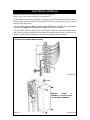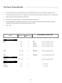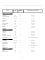
1
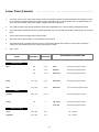
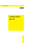
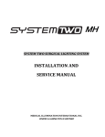
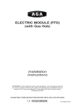
COMPANION (FFD)
(with Gas Hob)
OWNERS MANUAL
Cooking
Guide
included
inside
Comprising
Installation & Users
Instructions
&
Cooking
Guide
REMEMBER, when replacing a part on this appliance, use only spare parts that
you can be assured conform to the safety and performance specification that we
require. Do not use reconditioned or copy parts that have not been clearly
authorised by Aga
PLEASE READ THESE INSTRUCTIONS BEFORE USING THIS APPLIANCE
For use in GB and IE
09/07 EINS 511612
CONTENTS
SECTION
PAGE
INSTALLATION SECTION
3
INSTALLATION
4
TECHNICAL DATA
5
ELECTRICAL CONTROLS
6
LOCATION
7
PRODUCT DIMENSIONS
8
CONNECTING TO GAS
9
PRESSURE TESTING
10
USERS GUIDE
11
GENERAL INFORMATION
12
HEALTH & SAFETY
13
PRODUCT VIEW
14
CONTROL PANEL
15
GAS HOTPLATE
16
THE GRILL AND THE OVENS
17
OVEN COOKING GUIDE
18 - 22
CLEANING AND CARING FOR YOUR COOKER
23 - 25
SERVICING
26
WIRING DIAGRAM
27
2
Installation
Section
3
INSTALLATION
WARNING: THIS APPLIANCE SHALL BE INSTALLED IN ACCORDANCE WITH THE
REGULATIONS IN FORCE AND ONLY USED IN A WELL VENTILATED SPACE. READ THE
INSTRUCTIONS BEFORE INSTALLING OR USING THIS APPLIANCE.
PRIOR TO INSTALLATION, ENSURE THAT THE LOCAL DISTRIBUTION CONDITIONS
(NATURE OF GAS AND GAS PRESSURE) AND THE ADJUSTMENTS OF THE APPLIANCE
ARE COMPATIBLE.
THE ADJUSTMENT CONDITIONS FOR THIS APPLIANCE ARE STATED ON THE DATA
PLATE WHICH IS SITUATED IN THE CENTRE VENT SLOT NEAR THE BASE OF THE
FRONT PLATE
This appliance is not connected to a combustion products evacuation device. It shall be installed
and connected in accordance with current installation regulations. Particular attention shall be
given to the relevant requirements regarding ventilation. (B.S. 5440 Part 2: 1989)..
It should be in accordance also with any relevant requirements of the Gas Region and Local
Authority.
In your own interest, and that of safety to comply with the law, all gas appliances must be
installed by a competent person. Failure to install appliances correctly could lead to prosecution.
On completion, test the gas installation for soundness.
WARNING: THIS APPLIANCE MUST BE EARTHED
The appliance is designed for the voltage stated on the data plate.
The Companion is supplied from the manufacturers in a fully assembled and tested condition.
4
TECHNICAL DATA
HOTPLATE
NATURAL GAS G20 - (APPLIANCE CATEGORY I2H)
R.H.F.
L.H.R.
R.H.R.
L.H.F.
BURNER TYPE
ULTRA-RAPID RAPID
SEMI-RAPID
SEMI-RAPID
MAXIMUM HEAT
INPUT
3.5 kW
3.0 kW
1.75 kW
1.75 kW
INJECTOR MARKING
130
116
097
097
PRESSURE POINT POSITION: REAR LH SIDE OF APPLIANCE AT HOTPLATE LEVEL
PRESSURE SETTING:
20mbar
BURNER IGNITION: H.T. SPARK
PROPANE G31 - (APPLIANCE CATEGORY I3+)
R.H.F.
L.H.R.
R.H.R.
L.H.F.
BURNER TYPE
ULTRA-RAPID RAPID
SEMI-RAPID
SEMI-RAPID
MAXIMUM HEAT
INPUT
3.5 kW
(250g/h)
(0.50 l/h)
3.0 kW
(214g/h)
(0.42 l/h)
1.75 kW
(125g/h)
(0.25 l/h)
1.75 kW
(125g/h)
(0.25 l/h)
INJECTOR MARKING
95
85
65
65
PRESSURE POINT POSITION: REAR LH SIDE OF APPLIANCE AT HOTPLATE LEVEL
PRESSURE SETTING:
G30: 28-30 mbar
G31 - 37 mbar
BURNER IGNITION: H.T. SPARK
ELECTRIC GRILL AND OVENS
GRILL ELEMENT - POWER RATING 2 x 0.95 kW
TOP OVEN - POWER RATING 1.4kW
LOWER OVEN (FANNED) - 1.75kW
5
ELECTRICAL CONTROLS
Electrical connections are located at the back of the appliance
Refer to Figs. 1A for wiring connection to the appliance.
Remember that an excess of cable length is required for the possible withdrawal of the cooker.
Always double check connections and ensure terminals are fully tightened and the cable is
secured to the cable clamp.
THE ISOLATOR SHOULD NOT BE POSITIONED IMMEDIATELY ABOVE THE COMPANION
COOKER, BUT MUST BE SITED WITHIN 2 METRES OF THE APPLIANCE.
The Companion requires a 30 amp power supply fitted in conjunction with a double pole isolator
with a minimum contact clearance of 3mm and be connected to the mains with a minimum 4mm2
cable to comply with the latest editions of the local and national wiring regulations.
MINIMUM 4mm2 AND MUST COMPLY WITH THE LATEST EDITIONS OF THE LOCAL
AND NATIONAL WIRING REGULATIONS
DESN 513370
REMOVE
COVER
(4
SCREWS) TO GAIN ACCESS
TO THE MAINS TERMINAL
DESN 513372
FIG. 1A
6
LOCATION
This is a CLASS1, type X appliance.
Any side wall above the hob on either side shall be greater than 60mm horizontally from the
cooker only when adjacent to combustible material (Fig. 2).
Surfaces over the top of the cooker must not be closer than 650mm.
The vent slots in the back of the top plate must not be obstructed.
INSTALLATION/LEVELLING
The Aga Companion is designed to stand on a flat and level surface, however, any unevenness
may be overcome by packing under the corners of the plinth with a suitable non combustible
material, (up to 2-3mm).
7
PRODUCT DIMENSIONS
60mm*
600mm
910mm
948mm
595mm
1080mm
680mm
APPLIANCE CAN BE CLOSE
FITTED TO KITCHEN UNITS UP
TO WORK TOP HEIGHT.
116mm
* WHEN ADJACENT TO COMBUSTIBLE MATERIAL
DESN 511616
Fig. .2
8
CONNECTING TO GAS
This cooker can be installed with an approved appliance flexible connection. Supply piping
should not be less than R 1/2 (1/2” BSP). Connection is made to the R 1/2 (1/2” BSP) female
threaded entry in the inlet block located just below the hotplate level on the rear left hand side of
the cooker.
Check for gas soundness after connecting the gas supply.
390
480
279
558
TERMINAL BLOCK
COVER
200
460
573
DESN 511751
Fig. 3
The gas bayonet connector must be fitted in the shaded area indicated in Fig. 3 . Take into
account that it must be possible to pull the cooker forward sufficiently. Ensure flexible hose is not
trapped between electrics cover and rear wall. Ensure hose is routed within shaded area, and
away from shielded oven vent.
The flexible hose must be in accordance with the relevant standards.
NOTE: FOR L.P.G. APPLIANCE
The flexible hose must be suitable for use with Propane gas, capable of 70°C temperature rise,
and carry a red stripe, band or label. If in doubt contact your supplier.
9
PRESSURE TESTING
The pressure test point is situated at the rear left hand side of the appliance just below hotplate
level.
Remove screw from pressure test nipple. Fit the pressure gauge onto the pressure test nipple.
Place one of the burner heads and burner cap into position on the hotplate. Light this burner by
pushing in the appropriate control knob, and turning it anti-clockwise to the full on position.
For Natural Gas appliance, the pressure should be 20mbar (8 inches water gauge).
For LPG appliance the pressure should be Propane 37mbar and Butane 28-30mbar.
Turn off the tap, disconnect the pressure gauge and refit pressure test screw to pressure test
nipple.
Check for gas soundness.
10
Users
Guide
11
GENERAL INFORMATION
As responsible manufacturers we take care to make sure that our products are designed and
constructed to meet the required safety standards when properly installed and used.
IMPORTANT NOTICE: PLEASE READ THE ACCOMPANYING WARRANTY.
Any alteration that is not approved by Aga could invalidate the approval of the appliance,
operation of the warranty and could affect your statutory rights.
In the interests of safety and effective use, please read the following before using your new Aga
appliance.
The use of a gas cooking appliance results in the production of heat and moisture in the room in
which it is installed. Ensure that the kitchen is well ventilated: keep natural ventilation holes open
or install a mechanical ventilation device (mechanical extractor hood).
Prolonged intensive use of the appliance may call for additional ventilation, for example, opening
of a window, or more effective ventilation, for example increasing the level of mechanical
ventilation where present.
Installation must be to local and National wiring regulations and carried out by a Qualified
Engineer, from an authorised distributor.
A little smoke and some odour may be emitted when first switched on. This is normal and
harmless (from oven lagging and starch binder on the element insulation) and will cease after a
short period of use.
Your appliance has a gas hob, electric grill and two electric ovens. The upper oven is an electric
conventional oven with zoned heating, an electric grill is also incorporated in the roof of the oven.
The lower oven has an electric fan.The fan behind the rear panel ensures an even distribution
of heat within the cavity during cooking, ie temperature at lowest shelf position is the same as
the temperature at the highest shelf position.
Refer to the diagram (See Fig. 4) to familiarise yourself with the product and refer to the relevant
sections for upper oven, lower oven, grill, gas hotplate, etc.
The appliance, is fitted with a cooling fan, which functions during the use of the grill or top oven
(occasionally with the lower oven). The fan will continue to run after the grill/oven has been
turned off or until the unit has sufficiently cooled.
Your cooker is supplied with the following accessories:
3
1
1
1
Grid shelves, one of which is used as a grill shelf
Grill pan and grid - (FOR USE IN THE UPPER OVEN ONLY)
Roasting tin
Baking sheet
The following loose parts are also packed with the appliance:2
4
4
1
twin pan supports
hotplate burner heads
hotplate burner caps
burner ring (wok burner)
12
HEALTH & SAFETY
APPLIANCE
YOUNG CHILDREN SHOULD BE KEPT AWAY FROM THE APPLIANCE AS SOME SURFACES
CAN BECOME HOT TO TOUCH.
z
IMPORTANT: Oil is a fire risk, do not leave pans containing oil unattended.
z
In the event of fire cover with a lid and turn OFF the appliance.
Do not attempt to extinguish the fire using water.
Smother the flames on the hob preferably with a fire blanket, rather than attempting to
remove the pan to the outside.
Burns and injuries are caused almost invariably by picking up the burning pan to carry
outside.
Deep Fat Frying
z
Use a deep pan, large enough to completely cover the appropriate heating area.
z
Never fill the pan more than one-third full of fat or oil.
z
Never leave fat or oil unattended during the heating or cooking period.
13
RAPID BURNER
GAS HOTPLATE
SEMI RAPID BURNER
SEMI RAPID BURNER
WOK BURNER
CONTROL PANEL
REMOVABLE
LINER
GRILL PAN
WITH GRID
GRILL
SHELF
GRILL &
CONVENTIONAL
OVEN
GRID
SHELF
FANNED
OVEN
ROASTING TIN
(BAKING TRAY NOT SHOWN)
FOR USE IN BOTH OVENS
Fig. 4
DESN 511629 B
14
CONTROL PANEL
GAS HOB BURNERS
REAR
LEFT
FRONT
LEFT
REAR
RIGHT
FRONT
RIGHT
GRILL
TOP
OVEN
LOWER
OVEN
TOP
OVEN
NEON
Fig. 5
z
LOWER
OVEN
NEON
DESN 511620
The GAS HOTPLATE CONTROL KNOBS can only be rotated anti-clockwise from the OFF
position.
Large Flame Symbol - High Setting
Small Flame Symbol - Low Setting
(See ‘HOTPLATE’ section).
z
The GRILL ELEMENT KNOB can be rotated in any direction.
Clockwise
Anti-clockwise
Full on with, both elements on (graduated in red).
Economy grill, front elements only.
z
The OVEN KNOBS can only be rotated clockwise from the OFF position.
z
The OVEN NEONS illuminate when ovens are switched on. When the temperature
required is reached the neon will extinguish.
15
GAS HOTPLATE
z
The hotplate has four gas burners:
rear left - rapid burner - rated at 3.0 kW
front left and rear right - semi rapid burners - each rated at 1.75 kW
front right - ultra rapid (wok) burner - rated at 3.5 kW
z
The semi-rapid burners are especially suited for use with small pans and for gentle
simmering or poaching.
z
All burners have a set simmer position and are easily adjustable.
TO USE THE HOTPLATE
z
To light a hotplate burner: push in and turn the control knobs anti-clockwise to the large
flame symbol ( ), and hold in for 3 seconds until the burner lights, then turn the knob to
the required setting.
z
If the burner flame should accidentally go out, turn off the burner control and do not attempt
to re-light the burner for at least one minute.
z
The control may be set towards a lower position, simply by turning the control knob towards
the small flame symbol.
z
IMPORTANT: The cast iron pan supports on the appliance are much heavier than those on
most gas hotplate cookers, therefore care must be taken when removing or re-fitting them
to the hob. It is important that they are lifted from the appliance and not dragged across
nearby enamelled parts which would result in damaging the enamel.
SOME SAFETY POINTS
z
Simmering aids such as asbestos or mesh mats are not recommended. They may impede
burner performance, damage the pan supports and waste fuel.
z
Commercially available foil spillage aids are unnecessary on this cooker.
z
Some ‘Wok’ cooking parts are unstable. Check with the ‘Wok’ manufacturer before
purchasing.
z
DO NOT USE unstable and misshapen pans (e.g. with convex bases) that tilt easily.
z
The minimum pan diameter recommended is 120mm.
z
Place all pans centrally over the burners.
z
Always position pan handles away from the front of the cooker - away from the reach of
small children.
z
NEVER leave a chip pan unattended.
z
Pans and kettles with concave bases should not be used.
16
THE GRILL (TOP OVEN)
z
THE TOP OVEN DOOR MUST BE KEPT OPEN WHEN THE GRILL IS ON.
z
CAUTION: Accessible parts may be hot when the grill is in use. Young children should be
kept away.
z
The grill has 5 heat settings on each of 2 elements (see control panel).
z
For best results pre-heat at a high setting.
z
The large grill pan and grid supplied will fit on any of the three shelf positions.
z
Most foods should be cooked on the grill grid in the grill pan. You can turn the grid over
to suit the different thicknesses of food. You can place some dishes straight onto the oven
shelf this is useful when browning the top of food such as cauliflower cheese.
z
The cooker is supplied with one grid/grill shelf for the top oven.
THE OVENS
General
z
Both ovens are fitted with side and back self cleaning panels.
z
The shelves are designed to be non-tilt.
z
To remove a shelf, lift clear of the side notches and slide forward. To replace a shelf insert
into the oven with the short prongs at the rear, facing upwards. Slide into position above
the side notches then allow to drop down on the runner.
z
Do not place the grid shelf or food on the bases of the ovens. Food will burn on the base
of the top oven and air circulation will be affected in the lower oven.
z
Pre-heat the ovens at the appropriate settings until the neon light goes out.
z
When cooking in both ovens at the same time you may need to reduce the temperature
and cooking times (especially for baked foods).
z
For effective heat distribution, leave a gap of no less than 12mm between the dishes and
the sides of the oven, to allow hot air to circulate.
z
The large grill pan and grid are not designed to fit in the lower oven.
z
If you also have an Aga DO NOT use the small roasting tin provided with the Aga in the
Companion. Please use utensils provided and place on the grid shelves.
Condensation
Condensation may form on the cooker. This is quite normal and nothing to worry about. The
condensation forms when heat and moisture are present, for example during cooking.
Whenever possible try to make sure that food which contains a lot of moisture for example
casseroles are covered. If you do notice any condensation, wipe it up straight away.
17
OVEN COOKING GUIDE
Cooking Hints
z
Both ovens must be pre-heated until the neon light extinguishes.
z
The guidelines are for cooking after the oven(s) have reached the desired temperature.
z
Larger items may benefit from being turned.
z
Shelf positions are counted from the top.
z
Put dishes in the centre of the shelf.
z
When using both ovens together reduce cooking times and settings.
z
It is important to check that food is piping hot before serving.
z
You can change the settings and cooking times to suit your tastes.
Deep Fat Frying
z
Do not try to fry too much food at a time, especially frozen food.
This only lowers the temperature of the oil or fat too much, resulting in greasy food.
z
Always dry food thoroughly before frying, and lower it slowly into the hot oil or fat. Frozen
foods in particular, will cause frothing or spitting, if added too quickly.
z
Never heat fat, or fry with a lid on the pan.
z
Keep the outside of the pan, clean and free from streaks of oil or fat.
z
The following charts give a guide to cooking a number of everyday items.
18
Top Oven (Conventional)
Top Oven (Conventional) • Top Oven (Conventional) • Top Oven (Conventional)
z
The cooking charts are a general guide but times and temperatures may vary according to individual recipes.
z
The meat sections should be used as a guide but may vary according to the size, shape of joint on or off the bone.
z
Thaw frozen joints thoroughly before cooking them.
z
The times are for open roasting. If covered with foil allow for extra time.
z
The turkey/chicken is cooked when the juices run clear when pierced with a skewer. If the juices are still pink
continue to cook checking every 15 minutes until juices run clear.
z
1kg = 2.2lb
SETTING °C
SHELF
POSITION
180
3
Rare
35 mins per kg plus 20 mins
180
3
Medium
45 mins per kg plus 25 mins
180
3
Well Done
55 mins per kg plus 30 mins
Lamb
180 - 190
3
Well Done
55 mins per kg plus 25 mins
Pork
180 - 190
3
Well Done
1hr 5 mins per kg plus 30 mins
190 - 200
3
Large
220
3
25 - 40 mins
Individual
220
3
15 - 25 mins
FOOD
APPROXIMATE COOKING TIME
Roasting meat
Beef
Poultry
Chicken
45 mins per kg plus 20 mins
Yorkshire Pudding
19
Top Oven (Conventional) • Top Oven (Conventional) • Top Oven (Conventional) • Top Oven (Conventional) • Top Oven (Conventional)
SETTING °C
SHELF
POSITION
150
2
45 mins - 1hr
Very Rich Fruit Cake
130 - 140
3
3 - 4 hrs
Fruit Cake
150 - 160
3
1 - 2 hrs
Small Cakes
190
3
15 - 25 mins
Scones
220
3
10 - 20 mins
Victoria Sandwich
180
3
20 - 35 mins
Swiss Roll
210
2
10 mins
180 - 190
2
10 - 15 mins
180
3
30 - 35 mins
Plate Tarts
200
2
25 - 35 mins
Fruit Pie
200
3
35 - 45 mins
Mince Pies
200
2
20 - 25 mins
Vol-Au-Vents (frozen flaky)
220
3
15 - 20 mins
210 - 220
2
20 - 25 mins depending on size
Milk Puddings
150 - 160
3
2 hrs approx.
Baked Sponges
170 - 180
3
45 - 55 mins
Baked Custards
150
3
45 - 55 mins
Meringues
100
3
1.5 - 3 hrs depending on size
Apple Crumble
180
3
30 - 40 mins
Bread
220
3
30 - 40 mins
Rolls and Buns
220
3
10 - 20 mins
FOOD
APPROXIMATE COOKING TIME
Cakes and Biscuits
Shortbread
Biscuits
Tray Bakes
Pastries
Eclairs/Profiteroles
Puddings
Yeast Mixtures
20
Lower Oven (Fanned)
Lower Oven (Fanned) • Lower Oven (Fanned)• Lower Oven (Fanned)
z
The lower oven is a fan oven which means the air is circulated to create an even temperature throughout the oven.
In most cases this means that food requires a lower temperature when cooked in this oven, by approximately 10 20°C. Also some baked goods may require a slightly reduced cooking time.
z
The cooking charts are a general guide but times and temperatures may vary according to individual recipes.
z
The meat sections should be used as a general guide but may vary according to the size, shape of joint on or off the
bone.
z
Thaw frozen joints thoroughly before cooking them.
z
The times are for open roasting. If covered allow for extra time.
z
The turkey/chicken is cooked when the juices run clear when pierced with a skewer. If the juices are still pink
continue to cook checking every 15 minutes until juices run clear.
z
1kg = 2.2 lb
SETTING °C
SHELF
POSITION
170
2 or 3
Rare
35 mins per kg plus 15 mins
170
2 or 3
Medium
45 mins per kg plus 20 mins
170
2 or 3
Well Done
55 mins per kg plus 30 mins
Lamb
170 - 180
2 or 3
Well Done
55 mins per kg plus 20 mins
Pork
170 - 180
2 or 3
Well Done
1 hr 5 mins per kg plus 25 mins
180 - 190
2 or 3
170
3
FOOD
APPROXIMATE COOKING TIME
Roasting meat
Beef
Poultry
Chicken
Turkey
45 mins per kg plus 15 mins
Up to 4kg
40 mins per kg plus 10 mins
Over 4kg
30 mins per kg plus 20 mins
Yorkshire Pudding
Large
190 - 200
Any
25 - 40 mins
Individual
190 - 200
Any
15 - 25 mins
21
Lower Oven (Fanned) • Lower Oven (Fanned) • Lower Oven (Fanned) • Lower Oven (Fanned) • Lower Oven (Fanned)
SETTING °C
SHELF
POSITION
140
2 or 3
45 - 50 mins
Very Rich Fruit Cake
120 - 130
3
3 - 4 hrs
Fruit Cake
140 - 150
3
1 - 2 hrs
Small Cakes
180
Any
15 - 25 mins
Scones
200
Any
8 - 12 mins
Victoria Sandwich
170
Any
20 - 35 mins
Swiss Roll
200
2
10 mins
170 - 180
Any
10 - 15 mins
170
3
25 - 30 mins
Plate Tart
190
2 or 3
25 - 35 mins
Fruit Pie
190
2 or 3
25 - 45 mins
Mince Pies
190
1&3
20 - 25 mins
Vol-Au-Vents (frozen flaky)
210
1&3
15 - 20 mins
Eclairs/Profiteroles
200
2
20 - 25 mins depending on size
140
Any
2 hrs approx.
Baked Sponges
160 - 170
2 or 3
45 - 60 mins
Baked Custards
140
2 or 3
45 - 55 mins
Meringues
90
2 or 3
1.5 - 3 hrs depending on size
Apple Crumble
170
3
30 - 40 mins
Bread
200
2 or 3
25 - 35 mins
Rolls and Buns
200
2 or 3
10 - 20 mins
Cheese Souffle (individual)
190
3
20 - 25 mins
Cheese Souffle (Large)
190
3
25 - 35 mins
FOOD
APPROXIMATE COOKING TIME
Cakes and Biscuits
Shortbread
Biscuits
Tray Bakes
Pastries
Puddings
Milk Puddings
Yeast Mixtures
Souffle
22
CLEANING & CARING FOR YOUR COOKER
z
Always switch OFF at mains before cleaning.
z
Do not use a steam cleaner to clean this appliance.
z
When cleaning use as little water as possible.
z
Do not use abrasive pads, oven cleaner, or cleaners containing citric acid on enamelled
surfaces.
Surfaces that require cleaning are:
Enamelled Top and Front Plate
The easiest way to clean the Aga top plate and front plate is to mop up spills as they happen.
z
Baked on food is more difficult to clean but can usually be removed with proprietary vitreous
enamel cleaners or mild cream cleaners using a cloth, or if necessary, a nylon scouring pad.
z
If milk or fruit juice, or anything containing acid is spilt on the enamel, wipe off immediately.
z
Clean off any condensation streaks on the front plate around the oven doors or the vitreous
enamel may be permanently discoloured.
z
All that is usually needed to keep the vitreous enamelled surfaces of your cooker bright and
clean is a daily rub over with a damp cloth followed immediately with a clean, dry cloth to avoid
streaks.
z
Remember the top plate will scratch if pans or utensils are dragged across them.
z
Gas Hotplate
If spillage does occur on a burner cap or pan support, move pan to another burner and when
cool, clean in hot soapy water.
z
After cleaning, be sure all parts are dry. When fitting the burner cap and burner head, make sure
that the hole in the burner head is correctly located over the ignition electrode. (See Fig. 6A, 6B,
6C), and that the burner cap is sitting correctly on the burner head.
z
The ignition electrode must not be displaced or damaged otherwise spark ignition will be
affected.
z
The hotplate top is sealed. To clean, remove pan supports and wipe over visible surface.
z
PLEASE NOTE: The following parts MUST NOT be cleaned in a dishwasher, as this could
cause damage or discolour the finish:- pan supports, burner caps burner ring and burner head.
z
Aluminium pans may cause metallic marking on the pan supports. This will not affect the
durability of the enamel.
NOTE: The appliance guarantee does not cover the mis-use of the pan supports.
z
The Ovens
Both ovens are fitted with side and back panels which are of self cleaning enamel and
should not be scoured.
z
The removable grill deflector plate, the base of the top oven, and the base and roof of the fan
oven are vitreous enamelled and can be cleaned with proprietary vitreous enamel cleaners
approved by the Vitreous Enamel Association.
z
The shelves can be removed and if necessary the shelf supports may also be removed by
taking out the screws.
z
These items may be washed in the sink with normal oven cleaners, you may use a fine
wool soap pad for removing stubborn stains from the oven bases and shelf supports.
NOTE: TAKE CARE NOT TO DAMAGE THE THERMOSTAT PHIALS IN THE OVENS
WHEN CLEANING.
z
23
Heat-Clean Enamel
z
Fan oven - sides, top and back
Conventional oven/Grill compartment - sides and back
This special enamel has a continuous cleaning action, which works best if a pattern of low
and high temperature cooking is followed. By using low temperature roasting, excessive
fat splashes can be avoided. Should any excessive staining occur, immediately clean the
area with hot water containing detergent, and a nylon washing-up brush. Resistant stains
require the oven to be run at 210°C for 2 hours.
DO NOT USE ANY CLEANING MATERIAL WHICH MAY CLOG THE PORES OF THE
SPECIAL COATING E.G. PASTES AND POWDERS, SOAP FILLED PADS, WIRE WOOL,
SPRAY CLEANERS, BRUSH-ON OVEN CLEANERS, CAUSTIC SOLUTIONS, METAL
SCRAPERS/KNIVES AND PREVENT THE CONTINUOUS CLEANING ACTION.
Door Liners
z
May be cleaned with a cream cleaner or soap impregnated pad.
z
DO NOT immerse the doors in water as they are packed with insulating material which
will be damaged by excessive moisture.
Controls
z
The enamelled surface under the knobs can be treated as in the section ‘ Door Liners’.
Avoid the use of excessive water.
z
DO NOT use oven cleaners, scouring pads and abrasive powder for cleaning plastic knobs.
A wipe with a damp cloth should be sufficient.
IMPORTANT: Aga recommend Vitreous Enamel Association approved cleaners for cleaning
vitreous enamel surfaces of this product.
24
BURNER CAP
RETAINING LUGS
Fig. 6A
DESN 511617
Fig. 6B
DESN 513513
Fig. 6C
DESN 513898
25
SERVICING
z
In the event of your appliance requiring maintenance, please call Aga Service or contact
your authorised distributor/stockist.
z
Your cooker must only be serviced by a Qualified Engineer from an authorised
distributor/stockist.
z
Do not alter or modify the cooker.
z
Only the spares specified by the manufacturer, are to be fitted.
26
AGA COMPANION/MODULE (WITH GAS HOB UNIT)
UK & EUROPE
COLOUR KEY
BL
WH
R
BK
Y
PK
BR
P
GR
NOTE:
1.
IGNITION SWITCHES AND THERMOSTATS
ARE SHOWN IN THE OFF POSITION
WITH THE APPLIANCE COLD AND FAN
OVEN DOOR CLOSED.
2.
THE COOKER IS COLD
(IE. CUT-OUT NOT OPERATED)
27
-
BLUE
WHITE
RED
BLACK
YELLOW
PINK
BROWN
PURPLE
GREY
For further advice or information contact
your local distributor/stockist
With Aga's policy of continuous product
improvement, the Company reserves the right to
change specifications and make modifications to
the appliances described and illustrated at any
time.
Manufactured By
Aga
Station Road
Ketley Telford
Shropshire TF1 5AQ
England
www.aga-web.co.uk
www.agacookshop.co.uk
www.agalinks.com
28