1
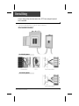
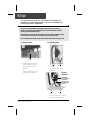
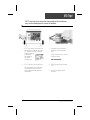
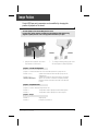
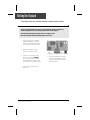
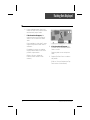
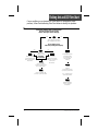
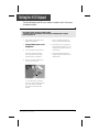
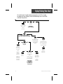
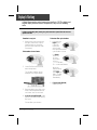
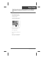
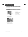
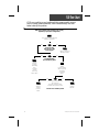
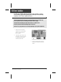
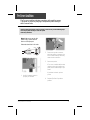
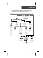
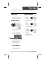
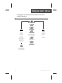
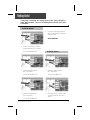
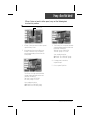
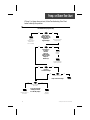
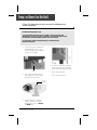
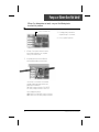
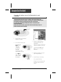
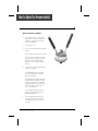
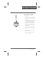
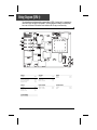
SSPA-1 & SSPA-MP SPA PACKS
SERVICE MANUAL
• by Gecko Electronics Inc. •
Visual step-by-step guide to easily
identify & correct technical problems!
GECKO
Table of Contents
Topics covered in this manual are as follows:
Power & Ground Check
Electrical Wiring
GFCI
6
7
Programming
Jumper Positions
10
Error Conditions
3 Flashing Dots Appearing On Keypad Display
3 Flashing Dots & LED Displayed
Display Is Flashing
Wrong Temperature Appearing On Keypad Display
FLO
FLC
Prr
HL
11
15
19
23
25
29
31
33
Troubleshooting
Nothing Seems to Work!
Spa Does Not Heat!
Pump 1 Does Not Work!
Pump 2 (or Blower) Does Not Work!
Light Does Not Work!
Ozonator Does Not Work!
Keys Do Not Work!
37
41
45
49
53
55
57
How to ...
Replace The Spa Pack
Adjust The Pressure Switch
59
62
Miscellaneous
Parts List
Wiring Diagrams
Professional Repair Kit Info
65
66
68
In an attempt to make this manual as useful as possible, it has been presented in two
formats. Problem-solving solutions are described with Troubleshooting Flow Charts
and also with Step-by-Step Procedures.
The two formats together should provide an overall complete explanation, with flow
charts providing an overview of specific problems, and step-by-step procedures giving
more detailed information.
Important Safety Information
WARNING: Risk of electrical shock! All procedures described in this service manual
must only be performed by qualified personnel, in accordance with the
standards applicable in the country of installation and, whenever
possible, with the equipment powered off. When connecting the
equipment, always refer to the wiring diagram affixed to the inside of
your spa pack’s power box cover! This diagram always prevails over
the wiring diagram at the end of this manual.
All information given subject to technical modifications without notice.
Tools & Parts
Tools, test equipment and components needed to carry
out SSPA power spa pack service calls.
Required tools:
Pliers
Phillips & flat screwdrivers
11/32" nut driver
1/4" open end wrench
3/8" open end wrench
Jumper cable
Multimeter
GFCI tester & digital thermometer (optional)
Required pack parts:
Fuses
Regulation sensor
SSPA complete pack
Pressure Switch
Top side control (keypad)
Gecko Electronic Inc. sells Professionnal Repair Kits that include everything needed for SSPA power spa pack servicing.
For more information, go to the last page of this manual.
SSPA Spa Pack Service Manual
4
Keypads
SSPA single- and dual-pump systems are available with
a selection of keypads.
All the procedures and instructions described in the next pages are applicable to
SSPA systems equipped with one of the following keypads. Please note that the
TSC-9 model is used througout this manual to illustrate specific actions.
SSPA-MP (only)
TSC-35 Keypad (7" • 3 1/4")
SSPA
TSC-19 Keypad (7" • 3 1/4")
TSC-18 Keypad (5" • 2 1/2")
TSC-9 Keypad (2" • 4 1/2")
5
SSPA Spa Pack Service Manual
Electrical Wiring
Correct wiring of the electrical service box, GFCI box and pack terminal
bloc is essential.
1• Carry out a visual inspection to check for signs of miswiring.
Refer to supplied wiring diagrams.
Call an electrician if necessary.
For 240 VAC systems:
L2
N
G
L1
Electrical Box
GFCI
Pack Terminal Block
For 120 VAC systems:
L2
N
G
L1
Pack Terminal Block
SSPA Spa Pack Service Manual
6
GFCI Flow Chart
If GFCI trips, follow this Troubleshooting Flow Chart to identify
the problem:
yes
no
Is GFCI
properly connected?
yes
no
Verify
Wiring Diagram
and reconnect it.
Is Spa Pack
a 120 VAC system?
yes
no
Is Jumper #1
in LC position?
(see page 10)
Change
Jumper #1 position.
yes
no
Is GFCI
still tripping?
yes
no
Unplug everything
including the two blades
of the heater & light cord.
Is GFCI
still tripping?
yes
There is
a problem
with the
cable.
Call an
electrician!
7
no
If GFCI is
still tripping,
disconnect
incoming
power line.
Reconnect
one component
at a time until
GFCI starts tripping.
Replace defective
component.
Replace
GFCI.
Is GFCI
still tripping?
Replace Spa Pack
if GFCI is still tripping.
SSPA Spa Pack Service Manual
GFCI Trips!
If all connections are made, but nothing seems to be working, you
probably have a power supply problem. Carry out the following tests
to identify and correct the problem:
Note that for new installations, GFCI trippings due to miswiring are common. If
breaker is wired properly, GFCI trippings may occur when total amount of current
drawn by spa exceeds breaker rating.
A current leak to ground will also cause GFCI to trip. If any of the components is faulty
and a leak of more than 5mA occurs, GFCI will trip to prevent electrocution.
There are different GFCI models on the market. Note that illustrations are generic only.
For 120 VAC systems:
For 240 VAC systems:
Jumper location
1• Verify if Jumper #1 is set in
the LC position. If it is not,
set Jumper #1 in the LC
position.
Refer to page 10 for more
information on jumpers.
From electrical box
To spa
1• Verify if GFCI is properly
connected.
Important
connections:
Neutral of GFCI
must be connected
to neutral bus.
Neutral from spa
must be connected
to breaker.
From electrical box
To spa
2• If it is not, verify GFCI wiring
diagram and reconnect it.
SSPA Spa Pack Service Manual
8
GFCI Trips!
If GFCI continues to trip even after having replaced the transformer,
carry out the following tests to correct the problem:
1• If GFCI is properly connected, but
still tripping, (or Jumper #1 is set in
LC mode for 120 VAC systems),
unplug all outputs
including the
two blades of
the heater
and light cord.
3• If problem is not solved yet,
disconnect incoming power
lines.
2• If GFCI still trips, replace Spa Pack.
4• If GFCI stops tripping, replace
GFCI.
If it stops tripping, reconnect one
component at a time until GFCI
starts tripping. Replace defective
component.
9
If GFCI still trips, there must be
a cable problem.
Call an electrician!
5• If GFCI trips again, replace
Spa Pack.
SSPA Spa Pack Service Manual
Jumper Positions
Certain SSPA spa pack parameters can be modified by changing the
position of jumpers on the board.
To access jumpers, first remove SSPA power box cover.
In some cases, jumper functions may differ from the following. Please check wiring
diagram on power pack box cover to verify specific functions for your pack.
Position 1
Position 2
Jumpers
1• Jumpers are located in the lower
right section of the board.
2• To change a setting, simply pull cover
off and replace in desired position.
Jumper 1: Current Limiting Option
Jumper 1 is used to limit amount of current drawn when the 2 pumps are on.
Position 1 (HC):
Position 2 (LC)*:
*Mandatory for 120 VAC systems
System turns heater off when the two pumps are on
at high speed.
System turns heater on when one pump is on at high
speed. The "Heater" icon flashes on display indicating
that more heat is requested, but heater is not allowed
to start.
Jumper 2: Temperature Unit
Jumper 2 is used to select the temperature unit.
Position 1:
Position 2:
Temperature will be displayed in Fahrenheit degrees.
Temperature will be displayed in Celsius degrees.
Jumper 3: Pumps
Position 1:
Position 2:
SSPA Spa Pack Service Manual
Single-pump.
Dual-pump (or blower).
10
Flashing Dots Flow Chart
If 3 flashing dots appear on keypad display, follow Troubleshooting Flow
Chart below to identify the problem:
3 flashing dots appear on the display!
yes
no
Remove pack cover.
Is board LED on?
Make sure jumper is
set properly for
circulation pump and
reset breaker.
Follow
flashing dots
& LED flow chart.
Start Pump 1 (or
circulation pump if installed
by increasing set point).
yes
no
Do you have
continuity on your
voltmeter for
pressure switch?
yes
Verify
pressure
switch
connection.
Short pressure
switch terminals
with a jumper cable.
no
Disconnect
pressure switch
for 5 seconds
and reconnect it.
yes
Try to adjust
pressure switch.
Are dots still
flashing on
keypad display?
Replace pressure
switch cable.
no
Are dots still
flashing on
keypad display?
Replace pressure
switch cable.
Replace pressure
switch if problem
persists.
If problem persists,
replace Spa Pack.
Remove anything
obstructing filter canister
or piping. Clear any air
locks. Verify water valves.
Try to adjust
pressure switch.
If problem persists,
replace Spa Pack.
Replace pressure
switch if problem
persists.
11
SSPA Spa Pack Service Manual
Flashing Dots Displayed
Three flashing dots error condition indicates a pressure switch problem.
There must be enough water in the spa for normal operations. System may detect error
condition if spa filter is dirty or if something restricts flow of water in piping.
The heater will automatically shut down when error condition occurs.
Power may remain On when the following steps are carried out.
1• Verify if Pump 1 (or circulation
pump if installed) is working. If
pump is not working right, refer
to pump section of this manual.
2• Make sure jumper is set properly for circulation pump.
3• If Pump 1 is working properly,
turn it on by pressing Pump 1
key (or start circulation pump
by increasing the set point) and
test continuity on pressure switch.
5• If you do not detect continuity,
verify if pressure switch cable is
properly connected to pressure
switch and board.
4• If you detect continuity, go to
step #10.
SSPA Spa Pack Service Manual
12
Flashing Dots Displayed
6• Ensure adequate water flow in the
heater and short two pressure switch
terminals with jumper cable.
7• If the three dots disappear, first
make sure there is no blockage of
water or air lock and check water
valve.
If the installation is older than 2 years,
replace the pressure switch and recalibrate it.
If installation is recent, try readjusting the pressure switch. If this is not
possible, replace switch.
(Refer to "How to Adjust the
Pressure Switch" section of this
manual.)
8• If the three dots still appear, the
problem may be either with switch
cable or board.
Remove plastic cover and replace
cable.
9• Replace Spa Pack if error condition
still persists.
(Refer to "How to Replace the Spa
Pack" section of this manual.)
13
SSPA Spa Pack Service Manual
Flashing Dots Displayed
Power may remain On while the following steps are carried out.
10• If you have continuity on pressure
switch, follow these steps:
Disconnect pressure switch cable
for 5 seconds and reconnect it.
If error condition disappears, adjust pressure switch, if it is a new
installation (less than two years) or
replace it.
11• If error condition persists, remove
plastic cover and replace pressure
switch cable.
12• Replace Spa Pack if error condition
still persists. (Refer to "How to Replace the Spa Pack" section of this
manual.)
(Refer to "How to Adjust the
Pressure Switch" section of this
manual.)
SSPA Spa Pack Service Manual
14
Flashing dots and LED Flow Chart
If error condition occurs (potential Hi-Limit sensor or temperature probe
problem), follow Troubleshooting Flow Chart below to identify the problem:
Turn breaker off then on again to reset the system.
If Hi-Limit condition no longer persists,
check for blockage of water in the piping.
yes
no
Take water temperature
with a digital thermometer.
Are you getting correct
water temp. reading on the display?
yes
Verify if anything
is obstructing water
flow (closed traps or
dirty filters).
no
When error
condition occurs,
does heater
barrel feel hot?
Is HL probe
properly connected?
Clean pins, reconnect
it, and reset
the breaker.
Verify if
temperature probe
is touching water
or if cold air from
back can affect
reading.
If error condition
persists, replace probe
and reset breaker.
Verify if
temperature probe
is properly connected.
If error condition still
persists, replace Spa Pack.
If so, replace probe
and reset breaker.
Replace Spa Pack
if error condition
still persists.
15
SSPA Spa Pack Service Manual
Flashing Dots & LED Displayed
The three flashing dots and LED error condition is related to the Hi-Limit sensor
or temperature probe.
Turn breaker off then on again to reset the system.
If 3 flashing dots and LED disappear, wait until they are displayed again on keypad.
Power may remain On.
1• Take water temperature with a
digital thermometer.
c- If error condition persists, replace probe and reset breaker.
2• If keypad display shows correct
temperature:
a- Check if heater barrel feels hot.
d- If problem is not corrected, replace Spa Pack. (Refer to "How
to Replace Spa Pack" section of
this manual.)
If it's hot, verify if anything is
obstructing the flow of water
(closed valves or dirty filter).
3• Proceed to following page if
keypad display shows incorrect
temperature.
b- If it's not, verify if hi-limit probe
is properly connected.
Probe
connector
pins
Try to clean probe connector
pins. Even a small coating of film
can cause a bad connection.
Reconnect probe and reset
breaker.
SSPA Spa Pack Service Manual
16
Flashing Dots & LED Displayed
If keypad display isn't showing correct temperature, carry out the
following tests:
1• Verify if temperature probe is
in contact with water and if
cold air from the back could
be affecting readings.
Use foam to isolate probe from
cold air if that is the problem.
2• Make sure temperature probe
is properly connected.
If it is, replace probe and reset
breaker.
3• Replace Spa Pack if error condition still persists. (Refer to
"How to Replace Spa Pack"
section of this manual.)
17
SSPA Spa Pack Service Manual
SSPA Spa Pack Service Manual
18
Display Flashing Flow Chart
On certain packs, if system detects temperature at 112°F or higher,
the display will start flashing. Follow Troubleshooting Flow Chart below
to identify the problem:
yes
no
Press
any key.
A power failure
has occurred.
Has display
stopped flashing?
System
works fine.
yes
no
Are you getting correct
water temp. reading on the display?
yes
no
Is weather
very hot?
Verify if
temperature probe
is touching water
or if cold air from
back can affect
reading.
If so, replace probe
and reset breaker.
Remove
spa cover
(even during
the night).
Start
blower, if
spa is
equipped
with one.
Wait until
spa cools
down (add
cold water
if needed).
19
yes
Replace
Spa Pack.
Verify if
temperature probe
is properly connected.
Replace
Spa Pack
if problem
still persists.
no
Lower set point
below actual
temperature of
water.
"Heater" indicator
on keypad display
should disappear.
Do you get a
240 VAC reading
between
two heater wires
on the board?
Pump is
overheating
water during
filter cycle.
Lower
filter cycle
duration.
SSPA Spa Pack Service Manual
Display Is Flashing
If digital thermometer water temperature reading is 112°F or higher and
keypad display indicates correct temperature, carry out the following
tests:
If display stops flashing after pressing a key, this means that a power failure has occurred.
System works fine.
If weather is very hot:
To shorten filter cycle duration:
1• Remove spa cover (even during
the night). Start blower if spa is
equipped with one. Wait until
spa cools down (add cold water
if necessary).
5• Press and hold
Light key for
5 seconds.
Display will
show a value
that represents the filter
cycle duration in hours.
If hot weather is not a factor:
Use Down
arrow key
to lower
the number
of hours.
0 = no filtration
12 = continuous filtration
2• Lower Set Point below current
water temperature.
The "Heater" indicator should
disappear from keypad display.
When the
desired setting
is displayed,
press Light key
again. The filter
cycle will start
immediately.
6• If you do read 240 VAC,
replace Spa Pack.
3• Remove plastic cover. With a voltmeter, read voltage between the
two heater wires on the board.
4• If you do not read 240 VAC, pump
may be overheating water during
filter cycle.
Shorten filter cycle duration.
SSPA Spa Pack Service Manual
20
Display Is Flashing
If digital thermometer water temperature reading is 112°F or higher and
keypad display isn't showing correct temperature, carry out the following
tests:
1• Verify if temperature probe
is in contact with water and if
cold air from the back could
be affecting readings.
Use foam to isolate probe from
cold air if that is the problem.
2• Make sure temperature probe
is properly connected.
If it is, replace probe.
3• Replace Spa Pack if display is still
flashing.
(Refer to "How to Replace Spa
Pack" section of this manual.)
21
SSPA Spa Pack Service Manual
SSPA Spa Pack Service Manual
22
Wrong Temperature Flow Chart
On certain packs, if system detects that temperature is not within normal
limits, wrong temperature will be displayed. Follow Troubleshooting Flow
Chart below to identify the problem:
Check if regulation
probe is properly connected.
Unplug probe connector
and clean pins on the
board (even a small coating
of film may cause a bad
connection).
Reconnect the probe.
Replace probe with
a spare and verify if
problem is solved.
If it is, replace
probe with spare.
Replace Spa Pack
if problem persists.
23
SSPA Spa Pack Service Manual
Wrong Temperature Displayed
Wrong temperature on keypad display indicates a problem with regulation
sensor. The system is constantly verifying if temperature probe reading is
within normal limits.
Note that water temperature must be over 35°F in order to carry out the following steps.
Power can remain On.
3• Reconnect probe.
If wrong temperature is still
displayed, replace probe with
a spare and place probe head
directly in spa water.
If problem is solved, replace
probe.
1• Verify if regulation probe (sensor
located in spa) is properly
connected.
4• Replace Spa Pack if problem
persists.
Probe
connector
pins
2• Disconnect probe connector
and clean probe connector pins.
Even a small coating of film may
cause a bad connection.
SSPA Spa Pack Service Manual
24
FLO Flow Chart
If FLO error condition occurs (problem with the pressure switch: pump is
on but no water pressure detected), follow Troubleshooting Flow Chart
below to identify the problem:
Make sure circulation pump parameter is set correctly
(depending on your system configuration).
There must be adequate water
in spa for normal use.
yes
no
Is pump working
when you try to start
it from keypad?
yes
Refer to "Pump not
Working" section.
no
Is anything limiting
flow of water into pipes?
Remove
anything
obstructing
filter.
Clear any
air locks
and verify
water valves.
Verify if
pressure switch
cable is properly
connected
to pressure
switch.
yes
Adjust or
replace
pressure
switch.
25
no
Lower Set Point at 60°F and
turn pump off.
Short two pressure switch
terminals with a jumper cable.
Does FLC error condition persist?
Replace
Spa Pack.
SSPA Spa Pack Service Manual
FLO Error Condition
An FLO error condition indicates a pressure switch problem. If system
does not detect any pressure when pump is manually or automatically
turned on, an FLO error condition will occur.
There must be enough water in the spa for normal operations. FLO error condition may
occur if spa filter is dirty or if something restricts flow of water in piping.
The heater will automatically shut down when an FLO error condition occurs.
Power may remain On when the following steps are carried out.
Make sure circ. pump parameter is set correctly (depending on your system configuration).
1• Verify if pump is working.
If pump is not working right,
refer to "Pump does not
Work" section.
2• Clean filter and check for air
blockages, closed trap valves
or anything that could be
restricting water flow.
3• Verify if pressure switch cable is
properly connected to pressure
switch.
SSPA Spa Pack Service Manual
26
FLO Error Condition
4• If problem has not been solved,
lower Set Point at 60° by pressing
on Down arrow key and turning
pump off; then short two pressure switch terminals with jumper
cable.
5• An FLC error condition should
occur.
FLC error condition identifies
pressure switch as source of
problem.
Try readjust pressure switch. If
this isn't possible, replace switch.
(Refer to "How to Adjust the
Pressure Switch" section of this
manual.)
6• If FLC error condition does not
occur, problem may be either
with switch cable or board.
Replace Spa Pack.
27
SSPA Spa Pack Service Manual
SSPA Spa Pack Service Manual
28
FLC Flow Chart
If FLC error condition occurs, follow Troubleshooting Flow Chart below to
identify problem (usually pressure switch problem - pump is off but water
pressure is detected):
yes
no
Disconnect
pressure switch cable
on pressure switch.
Does FLO error condition
occur when pump is on?
Adjust
pressure
switch.
Replace
Spa Pack.
Replace
pressure switch
if FLC error
condition
persists when
you start or
stop pump.
29
SSPA Spa Pack Service Manual
FLC Error Condition
An FLC error condition indicates a pressure switch problem. If
system detects any pressure when pump is off, an FLC error
condition will occur.
Power may remain On when the following steps are carried out.
1• Disconnect pressure switch cable
on pressure switch.
2• Replace Spa Pack if FLO error
condition does not occur.
If FLO error condition occurs when
pump is started, adjust pressure
switch or replace it.
(Refer to "How to Adjust the
Pressure Switch" section of this
manual.)
SSPA Spa Pack Service Manual
30
Prr Flow Chart
If Prr error condition occurs (potential regulation sensor problem), follow
Troubleshooting Flow Chart below to identify the problem:
Make sure to use the right probe!
MSPA-1 probe does not work on an SSPA spa pack.
Probe wires should be in this order:
PIN #4
Black
Green
Red
PIN #1
Press any key after each step to reset the system.
Note that water temperature
must be over 35˚F to operate spa.
Check if regulation
probe is properly connected.
Unplug probe connector
and clean pins on the
board (even a small coating
of film may cause a bad
connection).
Reconnect the probe.
Replace probe with
a spare and verify if
problem is solved.
If it is, replace
probe with spare.
Replace Spa Pack
if problem persists.
31
SSPA Spa Pack Service Manual
Prr Error Condition
The Prr error condition indicates a problem with regulation sensor.
The system is constantly verifying if temperature probe reading is
within normal limits.
Note that water temperature must be over 35°F in order to carry out the following steps.
Press any key after each step to reset the system.
Power may remain On.
Note: Make sure to use the right
probe! MSPA-1 probe does not
work on a SSPA spa pack.
Probe wires should be in this order:
Probe
connector
pins
PIN #4
Black
Green
Red
PIN #1
2• Disconnect probe connector
and clean probe connector pins.
Even a small coating of film may
cause a bad connection.
3• Reconnect probe.
If Prr error condition still persists,
replace probe with a spare and
place probe head directly in spa
water.
1• Verify if regulation probe is
properly connected.
If problem is solved, replace
probe.
4• Replace Spa Pack if problem
persists.
SSPA Spa Pack Service Manual
32
HL Flow Chart
If HL error condition occurs (potential hi-limit probe problem), follow
Troubleshooting Flow Chart below to identify the problem:
Press any key after each step to reset the system.
yes
no
Take water temperature
with a digital thermometer.
yes
no
Is water temperature
119°F or higher?
Are you getting correct water
temperature reading on the display?
yes
no
Is weather
very hot?
Remove
spa cover
(even during
the night).
Start
blower, if
spa is
equipped
with one.
Wait until
spa cools
down (add
cold water
if needed).
Verify if
temperature probe
is touching water
or if cold air from
back can affect its
reading.
yes
Replace
Spa Pack.
Verify if
temperature probe
is properly connected.
If so, replace
probe.
no
Lower Set Point
below actual
water temperature.
Pump is
overheating
water during
filter cycle.
"Heater" indicator
on keypad display
should disappear.
Replace
Spa Pack if
HL error
condition still
persists.
Lower
filter cycle
duration.
Do you get a
240 VAC reading
between the
two heater wires
on the board?
yes
Verify if anything
is obstructing water
flow (closed traps or
dirty filters).
No
When HL error
condition occurs,
does heater
barrel feel hot?
Verify if
Hi-Limit probe is
properly connected.
Try to clean pins
and reconnect
probe.
If HL error condition persists,
replace Spa Pack.
33
SSPA Spa Pack Service Manual
HL Error Condition
The HL error condition is related to the Hi-Limit sensor.
Steady message: Means system has shut down heater because water
temperature at the heater has reached 119ºF.
Blinking message: Means except for the Smart Winter Mode, system has shut
down because water temp. in the spa has reached 112ºF.
Press any key between each step to reset the system.
Power may remain On.
1• Take water temperature with
digital thermometer.
2• If reading is below 119°F:
a- Check if heater barrel feels hot.
If it's hot, verify if anything is
obstructing water flow
(closed valves or dirty filter).
b- If HL error condition persists,
replace Spa Pack.
3• If reading is 119°F or higher:
Proceed to following page if
keypad display shows correct
temperature.
Proceed to page 22 if keypad
doesn't show correct temperature.
SSPA Spa Pack Service Manual
34
HL Error Condition
If digital thermometer water temperature reading is 119°F or higher
and keypad display indicates correct temperature, carry out the
following tests.
If weather is very hot:
To shorten filter cycle duration:
1• Remove spa cover (even during
the night). Start blower if spa is
equipped with one. Wait until
spa cools down (add cold water
if necessary).
5• Press and hold
Light key for
5 seconds.
Display will
show a value
that represents the filter
cycle duration in hours.
If hot weather is not a factor:
Use Down
arrow key
to lower
the number
of hours.
0 = no filtration
12 = continuous filtration
2• Lower Set Point below current
water temperature.
The "Heater" indicator should
disappear from keypad display.
When the
desired setting
is displayed,
press Light key
again. The filter
cycle will start
immediately.
6• If you do read 240 VAC,
replace Spa Pack.
3• Remove plastic cover. With
a voltmeter, read voltage
between the two heater
wires on the board.
4• If you do not read 240 VAC,
pump may be overheating
water during filter cycle.
Shorten filter cycle duration.
35
SSPA Spa Pack Service Manual
HL Error Condition
If digital thermometer water temperature reading is 119°F or higher
and keypad display isn't showing correct temperature, carry out the
following tests.
1• Verify if temperature probe
is in contact with water and if
cold air from the back could
be affecting readings.
Use foam to isolate probe from
cold air if that is the problem.
2• Make sure temperature probe
is properly connected.
If it is, replace probe.
3• Replace Spa Pack if HL error
condition still persists.
SSPA Spa Pack Service Manual
36
"Nothing Seems to Work!" Flow Chart
If nothing seems to work, follow Troubleshooting Flow Chart below
to identify the problem:
yes
no
For 240 VAC systems:
Verify if
keypad is
connected
correctly
to board.
All eight pins
must be plugged in
and black wire
must be on top
of the plug.
Do you read
≈ 240 VAC
between
line 1 & line 2,
≈ 120 VAC
between
line 1 & neutral,
≈ 120 VAC
between
line 2 & neutral
on the board?
For 120 VAC systems:
Do you read
≈ 120 VAC
between
line 1 & neutral?
There is
an electrical
wiring
problem.
Call an
electrician.
Is there a
jumper cable
connected
between
line 2 & neutral?
Replace Spa Pack
if there is still nothing
on keypad display.
37
SSPA Spa Pack Service Manual
Nothing Works!
If everything is connected, but nothing seems to work, there is probably a
power supply problem. Carry out the following tests to identify and correct
the problem:
For 240 VAC systems:
4• If you do not get good readings,
this probably indicates an electrical
wiring problem.
Call an electrician!
1• On the terminal block, measure
voltage between line 1 and line 2.
You should get ≈240 VAC.
For 120 VAC systems:
2• Measure voltage between
line 1 and neutral.
1• Measure voltage between
line 1 and neutral.
You should get ≈120 VAC.
You should get ≈120 VAC.
3• Measure voltage between
line 2 and neutral.
You should get ≈120 VAC.
SSPA Spa Pack Service Manual
2• Verify that there is a jumper cable
connected between line 2 and
neutral.
38
Nothing Works!
If you are getting good voltage readings, but nothing seems to work,
carry out the following tests to correct the problem:
1• Verify if keypad is correctly
connected to the board.
2• If nothing works, replace
Spa Pack.
39
SSPA Spa Pack Service Manual
SSPA Spa Pack Service Manual
40
"Spa Not Heating" Flow Chart
If the spa does not seem to be heating the water, follow Troubleshooting
Flow Chart below to identify the problem:
yes
Refer to
specific section
referred to
error message.
no
Any error messages
(FLO, FLC, 3 flashing dots, etc.)
on keypad display?
yes
Ensure temp.
Set Point is
higher than
actual water temp.
no
Has "Heater" indicator appeared
on keypad display?
yes
no
yes
no
Take water temp.
and compare with
temp. value displayed
on keypad.
Do you get a 240 VAC
reading between
the two heater
terminals
on the board?
Is difference
greater than ±2°F?
System
works fine.
Is temp. probe
touching water or
hot air rear
affecting reading?
Replace
Spa Pack.
yes
Isolate back of
probe with foam.
no
Are heater nuts
connected
properly
to the
element?
Replace
temp. probe
with spare.
yes
no
Try tightening nuts
to element.
Still not heating?
If water temp.
still doesn't
match temp.
on keypad display,
replace Spa Pack.
Replace
element.
41
SSPA Spa Pack Service Manual
Spa Not Heating!
If the spa does not appear to be heating the water, carry out
the following tests to correct the problem:
If "Heater" indicator does not
light up:
1• Check for an error condition
on keypad display. If there is
one, refer to section indicated
by the error condition.
"Set Point"
indicator
4• Use a digital thermometer to take
water temperature and compare
your reading with the value on
keypad display.
If values are different (±2°F), verify if
sensor is touching water or if hot air
from rear could be affecting readings.
5• If so, use foam to isolate behind
the probe.
2• If there is no message, try to
increase temperature by raising
temperature Set Point. Press Up
arrow key to increase Set Point.
"Heater"
indicator
3• Verify if "Heater" indicator appears
on the display.
"Heater" indicator will be on when
heater is on. It will flash if more
heat has been requested, but
heater has not yet started.
SSPA Spa Pack Service Manual
6• If not, replace temperature sensor
with a spare one.
7• If spa is still not heating, replace
Spa Pack.
42
Spa Not Heating!
If "Heater" indicator appears on the display, but spa is still not heating,
carry out the following tests to correct the problem:
If "Heater" indicator lights up on the display:
1• Remove plastic cover and measure
voltage between the two heater
screws on the board.
Replace board if you are not
getting a reading of ≈240 VAC.
2• If voltage reading is correct,
verify if heater nuts are
properly connected to the
element.
If not, tighten nuts to the
element.
3• If problem persists, replace
the element.
43
SSPA Spa Pack Service Manual
SSPA Spa Pack Service Manual
44
Pump 1 Flow Chart
If Pump 1 is not working, follow Troubleshooting Flow Chart below
to identify the problem:
yes
no
Have any error
messages (FLO, FLC,
3 flashing dots, etc.)
appeared on
keypad display?
Refer to
specific section
indicated by
error message.
yes
Verify if Jumper #3
is set properly.
no
Does "Pump 1"
indicator
appear on
keypad display
when you press
Pump 1 key?
Replace
keypad.
If still not working,
replace Spa Pack.
yes
no
Is Pump 1 working
in either speed?
yes
no
Replace Pump 1 fuse.
Pump 1 still not working!
yes
no
Measure voltage on
the board for both speeds.
Replace
Pump 1.
45
Do you get a 240 VAC
reading (or 120 VAC
for a 120 VAC pump)
for both speeds?
Replace
Spa Pack.
SSPA Spa Pack Service Manual
Pump 1 Does Not Work!
If Pump 1 is not working, carry out the following tests to correct
the problem:
To increase the life of the relay, we use a "snubber" circuit on the pump relay.
With this type of circuit, if no pump is connected to an output and relays are open,
the voltmeter will continue reading around 60 volts. This is normal.
It is important to measure voltage when pump is connected to pack.
Power must remain On.
1• Check for an error condition on
keypad display. If there is one,
refer to specific section indicated
by the error condition.
4• If "Pump 1" indicator does not appear,
use a spare keypad to verify if keypad
is defective.
Jumpers
If it is, replace keypad.
2• Also, verify that Jumper #3 is
set properly for 1 or 2 pumps
(refer to page 10 for more info).
"Pump 1"
indicator
If not, replace Spa Pack.
5• If "Pump 1" indicator appears when
Pump 1 key is pressed, verify if pump
works in either speed.
3• Verify if "Pump 1" indicator appears
on keypad display when you press
Pump 1 key.
SSPA Spa Pack Service Manual
46
Pump 1 Does Not Work!
If Pump 1 does not work in either speed, carry out the following tests
to correct the problem:
Pump 1 fuse
1• If Pump 1 does not work in either speed,
replace Pump 1 fuse.
2• If replacing the fuse is not effective or
if Pump 1 works in only one speed,
take voltage reading on the board for
both speeds.
3• Turn Pump 1 to low speed and take
voltage reading between white and
black wire connectors:
240 VAC pump: P14 & P18
120 VAC pump: P7 & P14
Your reading shoud be:
≈240 VAC for a 240 VAC pump
≈120 VAC for a 120 VAC pump
4• If voltage is as it should be,
replace Pump 1.
5• If not, replace Spa Pack.
Turn Pump 1 to high speed and take
voltage reading between white and
red wire connectors:
240 VAC pump: P12 & P18
120 VAC pump: P7 & P12
Your reading shoud be:
≈240 VAC for a 240 VAC pump
≈120 VAC for a 120 VAC pump
47
SSPA Spa Pack Service Manual
SSPA Spa Pack Service Manual
48
Pump 2 or Blower Flow Chart
If Pump 2 or blower does not work, follow Troubleshooting Flow Chart
below to identify the problem:
For SSPA Dual-Pump Systems only!
yes
no
Have any error
messages (FLO, FLC,
3 flashing dots, etc.)
appeared on
keypad display?
Refer to
specific section
indicated by
error message.
yes
Verify if Jumper #3
is set properly.
no
Does "Pump 2"
or "Blower"
indicator
appear on
keypad display
when you press
Pump 2 or
Blower key?
Replace
keypad.
If still not working,
replace Spa Pack.
yes
no
Is Pump 2
or blower working?
yes
no
Replace blower fuse.
Pump 2 still not working!
yes
no
Measure voltage on
the board.
Do you get a 240 VAC
reading (or 120 VAC
for a 120 VAC pump)?
Replace Pump 2
or blower.
49
Replace
Spa Pack.
SSPA Spa Pack Service Manual
Pump 2 or Blower Does Not Work!
If Pump 2 or blower does not work, carry out the following tests to
correct the problem:
For SSPA Dual-Pump Systems only!
To increase the life of the relay, we use a "snubber" circuit on the pump relay.
With this type of circuit, if no pump is connected to an output and relays are open,
the voltmeter will continue reading around 60 volts. This is normal.
It is important to measure voltage when pump is connected to pack.
Power must remain On.
1• Check for an error condition on
keypad display. If there is one,
refer to specific section indicated
by the error condition.
4• If "Pump 2" or "Blower" indicator
does not appear, use a spare keypad to verify if keypad is defective.
Jumpers
2• Also, verify that Jumper #3 is
set properly for 2 pumps (refer
to page 10 for more info).
If it is, replace keypad.
If not, replace Spa Pack.
"Pump 2"
indicator
3• Verify if "Pump 2" or "Blower"
indicator appears on keypad
display when you press Pump 2
or Blower key.
SSPA Spa Pack Service Manual
50
Pump 2 or Blower Does Not Work!
If Pump 2 or blower does not work, carry out the following tests
to correct the problem:
Pump 2 or blower fuse
3• If voltage is as it should be,
replace Pump 2 or blower.
4• If not, replace Spa Pack.
1• If Pump 2 or blower does not work
even when indicator is on, replace
Pump 2 or blower fuse.
2• If replacing the fuse is not effective,
take voltage reading on the board.
Turn Pump 2 or blower on and take
voltage reading between white and
black wire connectors:
240 VAC pump or blower: P11 & P17
120 VAC pump or blower: P9 & P11
Your reading shoud be:
≈240 VAC for a 240 VAC pump or blower
≈120 VAC for a 120 VAC pump or blower
51
SSPA Spa Pack Service Manual
SSPA Spa Pack Service Manual
52
Spa Light Flow Chart
If spa light does not appear to be working, follow Troubleshooting Flow
Chart below to identify the problem:
no
yes
Have you
tried replacing
the spa
light bulb?
yes
yes
Try
replacing
light bulb.
Is light
still not
lighting
up?
no
Does "Light"
indicator
appear on
keypad
display when
you press
Light key?
no
Replace
keypad.
If still not
working,
replace
Spa Pack.
yes
Replace spa
light socket.
no
Do you get a
12 VAC reading
on light output
on board?
Replace spa
light fuse.
Replace Spa Pack
if light is still not working.
53
SSPA Spa Pack Service Manual
Spa Light Does Not Work!
If spa light is not working, carry out the following tests to correct
the problem:
It is important to measure voltage when light is connected to pack.
Power must remain On.
1• The first step is to replace the
spa's light bulb.
"Light"
indicator
2• If light still isn't working, verify if
"Light" indicator appears on
keypad display when you press
Light key.
4• If "Light" indicator appears, but
light still isn't working, remove
plastic cover and measure
voltage between two light wires
on the board.
If you get ≈12 VAC, replace light
socket.
Light fuse
3• If "Light" indicator doesn't appear,
use a spare keypad to verify if spa
keypad is defective.
If it is, replace keypad.
If not, replace Spa Pack.
SSPA Spa Pack Service Manual
5• If you aren't getting a voltage
reading, replace light fuse on
the board.
6• If problem persists, replace
Spa Pack.
54
Ozonator Flow Chart
If the ozonator is not working, follow Troubleshooting Flow Chart below
to identify the problem:
Ozonator output will be shut down when
Pump 1, Pump 2 or blower have been turned on manually.
yes
no
Has "Filter Cycle"
indicator
appeared on
keypad display?
yes
Start up
a filter
cycle.
no
Do you read
120 VAC for a
120 VAC ozonator
(or 240 VAC for 240 VAC)
on the board?
yes
no
Is Pump 1
working?
Replace
ozonator.
55
Replace Spa Pack
if you still
aren't getting
a voltage reading.
Refer to
"Pump 1 does
not Work!"
section.
SSPA Spa Pack Service Manual
Ozonator Does Not Work!
If ozonator isn't working, carry out the following tests to correct
the problem:
To increase the life of the relay, we use a "snubber" circuit on the ozonator relay.
With this type of circuit, if no ozonator is connected to an output and relays are open,
the voltmeter will still get a reading of around 60 volts. This is normal.
It is important to take voltage reading when ozonator is connected to pack.
Power must remain On.
Please take note that ozonator output will be shut down when Pump 1, Pump 2 or
blower have been turned on manually.
"Filter Cycle"
indicator
1• Verify if "Filter Cycle" indicator
appears on keypad.
2• If not, start up a filter cycle.
Press and hold
Light key for
5 seconds.
The display
will show a
value that
represents the filter
cycle duration in hours.
Press Light key
again. The filter
cycle will start
immediately.
3• Measure voltage between
ozonator black and white
connectors:
240 VAC ozonator: P16 & P19
120 VAC ozonator: P16 & P8
You should read ≈240 VAC
(≈120 VAC for a 120 VAC
ozonator).
4• Replace ozonator if you get a
good voltage reading.
5• Check if Pump 1 is working.
If so, replace Spa Pack.
If Pump 1 is not working, refer
to "Pump 1 does not Work!"
section.
SSPA Spa Pack Service Manual
56
Keys Flow Chart
If any of the keys on the keypad do not seem to be working, follow
Troubleshooting Flow Chart below to identify the problem:
Make sure to use the proper keypad: TSC-35 keypad with SSPA-MP spa pack.
TSC-18, TSC-19 or TSC-9 keypad with SSPA-1 spa pack.
Also refer to Jumper Section (p. 10) to see if outputs are set correctly.
yes
no
Is Jumper #3
set properly for 1 or
2 pumps?
Set Jumper #3
properly.
Unplug spa keypad
and replace with
spare keypad.
yes
no
Are keys
working?
Replace
keypad.
57
Replace
Spa Pack.
SSPA Spa Pack Service Manual
Keys Don't Work !
If any of the keys do not seem to be working, carry out the following tests
to correct the problem:
Make sure to use the proper keypad: TSC-35 keypad works with a SSPA-MP spa pack. TSC-18,
TSC-19 or TSC-9 keypad works with a SSPA-1 spa pack. Also refer to Jumper Section (p. 10) to
see if outputs are set correctly.
Jumpers
1• Verify that Jumper #3 is set properly for 1 or 2 pumps (refer to
page 10 for more info.)
3• Verify if keys respond correctly.
4• If they do, replace keypad.
5• If they do not respond,
replace Spa Pack.
2• Replace spa keypad with a
spare keypad.
SSPA Spa Pack Service Manual
58
How To Replace The Spa Pack
When replacing an SSPA spa pack, it is important to make sure to turn
power off before proceeding.
1• Unplug Pump 1, Pump 2 (or blower)
and ozonator connectors.
2• Remove 2 screws from front pack cover.
3• Lift the Spa Pack cover.
59
SSPA Spa Pack Service Manual
How To Replace The Spa Pack
When replacing an SSPA spa pack, it is important to make sure to turn
power off before proceeding.
4• Disconnect power input cables.
Light
Keypad
Probe
5• Disconnect light cables, keypad
and temperature probe connectors.
7• Disconnect heater ground
cable.
6• Disconnect pressure switch
cable.
8• With wrenches, free the
board blades by removing
the 2 heater nuts.
SSPA Spa Pack Service Manual
60
How To Replace The Spa Pack
When replacing an SSPA spa pack, it is important to make sure to turn
power off before proceeding.
9• Slide the pack out of the heater
barrel.
13• Reconnect light cables, keypad
and temperature probe.
10• Check if high-limit sensor is
properly in place in its slot and
slide new pack into position.
14• Plug in Pump 1, Pump 2 (or
blower) and ozonator connectors.
11• Connect heater to the board
blades. It is important to hold
both nuts when tightening. If
you bend or twist the end of
the element, you may damage
it.
15• Reconnect power input
cables.
16• Close pack cover.
12• Reconnect heater ground
cable and pressure switch
cables.
61
SSPA Spa Pack Service Manual
How To Adjust The Pressure Switch
When a voltmeter is available:
1• Set voltmeter to "Ω" (while both
probes are touching one another,
voltmeter should beep to show
there is continuity).
2• Turn Pump 1 off.
3• Do you have continuity on pressure
switch?
If you have no continuity, go to step 4.
If you do have continuity, increase
pressure switch setting by turning
clockwise until voltmeter stops
beeping. Then, increase another
full turn.
4• Turn Pump 1 on at low speed and
wait a few minutes.
If (3) flashing dots do not appear,
you have adjusted the pressure
switch successfully.
If (3) flashing dots appear, decrease
pressure switch setting by turning
counter clockwise until voltmeter
starts beeping (there is continuity).
Then, decrease another 1/4 of
turn. Turn pump off.
The (3) flashing dots should not
appear (restart procedure if (3)
flashing dots appear).
5• When adjustment procedure is
completed, apply Loctite 425 to
the adjustment screw to secure
it in place.
SSPA Spa Pack Service Manual
62
How To Adjust The Pressure Switch
When a voltmeter is not available:
1• Turn Pump 1 off.
2• Decrease the pressure switch setting
to 0.5 P.S.I. or until three flashing dots
are displayed.
3• Start increasing pressure switch setting
by very slowly turning adjustment
screw clockwise until three flashing
dots disappear, then another full turn.
4• Turn pump on at low speed for 30
seconds; there should be no flashing
dots on display.
5• Turn pump off and wait 30 seconds.
You should not see the three flashing
dots.
6• If you see an error, restart the adjustment procedure.
If you are not able to adjust the pressure switch, change it.
63
SSPA Spa Pack Service Manual
SSPA Spa Pack Service Manual
64
Parts List
We recommend that field service technicians keep the items identified
with an * in stock.
Ref.: Part Number
Description
1
1
2
4
6
6
6
6
6
6
6
6
6
6
6
6
12
12
13
19
22
23
29
30
Tail piece for 2" heater
Gasket for 2" tail piece (package of 5)
Nut for 2" heater
Light cords (option LS)
J&J mini connector for pump 1
J&J mini connector for pump 2, single speed
J&J mini connector for pump 2, two speeds
J&J mini connector for ozone
J&J mini connector for blower
J&J mini connector for circulation pump
AMP connector for pump 1
AMP connector for pump 2, single speed
AMP connector for pump 2, two speeds
AMP connector for ozone
AMP connector for blower
AMP connector for circulation pump
In-line 5.5Kw heater
5.5Kw 240V element for in-line heater
Pressure switch
Ground screws (package of 25)
Fuses for light (package of 10)
Fuses for pumps (package of 10)
Fuses for transformer
10-foot temperature probe
530AB0061
530AB0042-P5
282CA0071
9920-400178
9920-400200
9920-400199
9920-400200
9920-400204
9920-400203
9920-400205
9920-400277
9920-400276
9920-400277
9920-400278
9920-400278
9920-400276
530AA0107
530AB0087
510AD0064
282AD0038-P25
430AC0103-P10
430AE0033-P10
430AD0066-P10
9920-400262
Suggested Retail U.S.
CDN
5.39
8.00
4.90
7.57
7.26
6.68
7.26
5.92
5.92
5.92
7.26
6.68
7.26
6.68
6.68
6.68
143.17
88.20
28.42
9.86
11.14
56.57
11.14
19.20
7.33
10.88
6.67
10.3
9.88
9.09
9.88
8.06
8.06
8.06
9.88
9.09
9.88
9.09
9.09
9.09
194.79
119.99
38.67
13.42
15.15
76.97
15.15
26.12
*
*
*
*
*
*
*
5
9
1
4
2
8
3
10
7
6
Prices subject to change without prior notice.
65
SSPA Spa Pack Service Manual
Wiring Diagram (SSPA-1)
The wiring diagram below provides a general idea of SSPA-1 wiring, but it is important to
note that it may not apply to all systems. The wiring diagram including on inside power
box cover is the one to be used as main reference for the spa you are servicing.
Pump 1
Voltage
Green / Ground
Black / Low Speed
Red / High Speed
White / Com
240v
P4
P14
P12
P18
Pump 2
Voltage
Green / Ground
Black / Line
White / Com
240v
P6
P11
P17
Jumper Settings
Refer to page 10
Ozonator
Voltage
Green / Ground
Black / Line
White / Neutral
120v
P5
P16
P8
Light Connector
White / 0 VAC
Black / 12 VAC
P23
P22
Heater
Black 1
Black 2
P20
P21
Pressure Switch
Green
Red
P25
P24
Wiring Diagram (SSPA-MP)
The wiring diagram below provides a general idea of SSPA-MP wiring, but it is important
to note that it may not apply to all systems. The wiring diagram including on inside
power box cover is the one to be used as main reference for the spa you are servicing.
Pump 1
Voltage
Green / Ground
Black / Low Speed
Red / High Speed
White / Com
120v 240v
P4
P4
P14 P14
P12 P12
P7
P18
Pump 2
Voltage
Green / Ground
Black / Line
White / Com
120v 240v
P6
P6
P11 P11
P9
P17
Jumper Settings
Refer to page 10
Ozonator
Voltage
Green / Ground
Black / Line
White / Com
120v 240v
P5
P5
P16 P16
P8
P19
Blower
Voltage
Green / Ground
Black / Line
White / Com
120v 240v
P37 P37
P34 P34
P35 P36
Fiber Box
Voltage
Green / Ground
Black / Line
White / Neutral
120v
P1
P33
P35
Light Connector
White / Light
Black / 12 VAC
P23
P22
Heater
Black 1
Black 2
P20
P21
Pressure Switch
Green
Red
P24
P25
Professional Repair Kit
All you need in one case!
Gecko's professional repair kit contains
all you need to service and repair
Gecko's line of power spa packs.
•
•
•
•
•
•
•
•
•
•
•
•
•
•
•
Call 1.800.78.GECKO
to order or for more info!
Top side controls (keypads)
Temperature probes
Pressure switch cables
Flow switches
Elements
Heater wires
Transformer
Ground lugs
Grommets
Standoffs
Light cords
Strain reliefs for light cord
Plugs
Fuse kits
Screws
SSPA SERVICE MANUAL
COMPLETE SERVICE GUIDE WITH
STEP-BY-STEP INSTRUCTIONS ON:
GFCI Troubleshooting
•
Jumper Setup
•
Understanding
& Correcting
Error Conditions
•
System Malfunctions
•
Part Replacement
Procedure
•
& More
GECKO
9919-100298
1.877.78.GECKO • www.gecko-electronic.com